Chapter III - KOCWcontents.kocw.net/KOCW/document/2016/chungang/leejinhyung/3.pdf · A hollow shaft...
58
Chapter III
Transcript of Chapter III - KOCWcontents.kocw.net/KOCW/document/2016/chungang/leejinhyung/3.pdf · A hollow shaft...
Chapter III
TORSION
1.Introduction 2.Torsion Deformation of a Circular Bar 3.Circular Bars of Linearly Elastic Materials 4.Nonuniform Torsion 5.Stresses and Strains in Pure Shear 6.Relationship Between Moduli of Elasticity E and G 7.Transmission of Power by Circular Shafts 8.Statically Indeterminate Torsional Member 9.Strain Energy in Torsion and Pure Shear 10.Thin-Walled Tube 11.Stress Concentration in Torsion
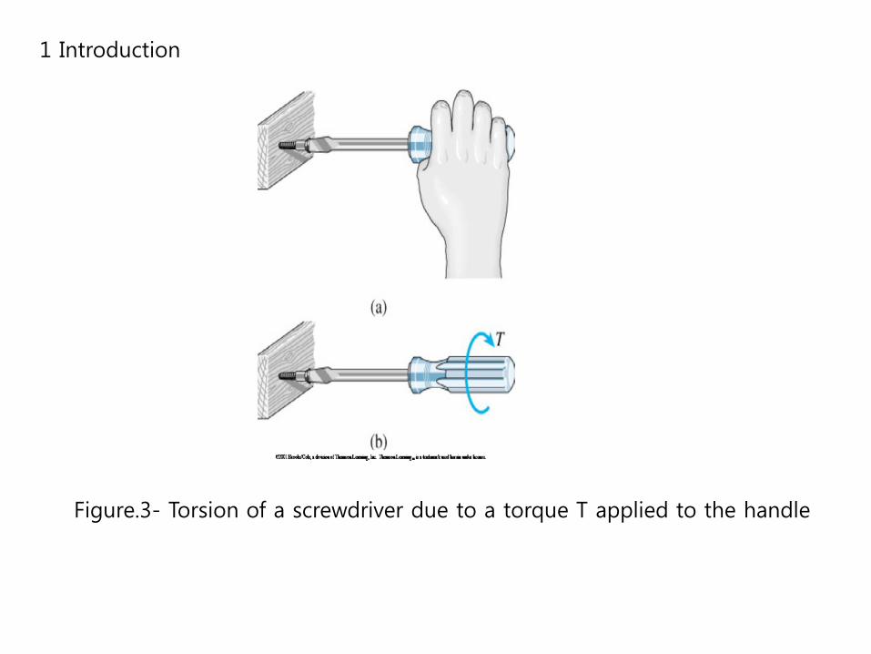
1 Introduction
Figure.3- Torsion of a screwdriver due to a torque T applied to the handle
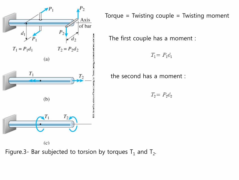
Figure.3- Bar subjected to torsion by torques T1 and T2.
Torque = Twisting couple = Twisting moment
the second has a moment :
The first couple has a moment :
In this chapter
1) We began by developing formulas for the deformations and stresses in circular bars subjected to torsion.
2) We analyze the state of stress known as pure shear.
3) We obtain the relationship between the moduli of elasticity E and G in tension and in shear.
4) We analyze rotating shafts and determine the power they transmit.
5) We cover statically indeterminate member, strain energy, thin-walled tubes of noncircular , stress concentrations and nonlinear behavior.
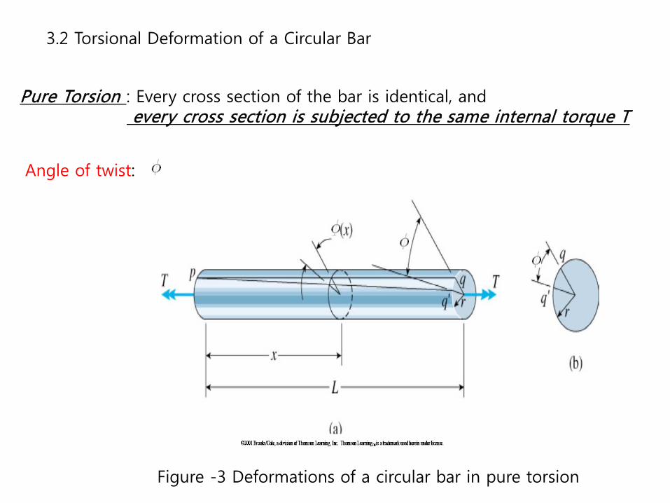
3.2 Torsional Deformation of a Circular Bar
Pure Torsion : Every cross section of the bar is identical, and every cross section is subjected to the same internal torque T
Angle of twist:
Figure -3 Deformations of a circular bar in pure torsion
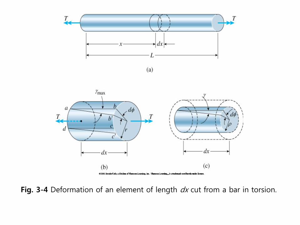
Fig. 3-4 Deformation of an element of length dx cut from a bar in torsion.

The magnitude of the shear strain
is equal to the increase in the angle at point a.
From the figure(Fig.3-4b)
: This quantity is the rate of change of the angle of twist
with respect to the distance
: Angle of twist per unit length or Rate of twist
∴
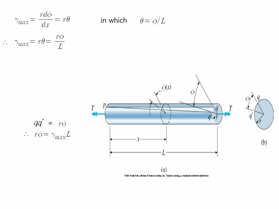
in which
∴
=
∴
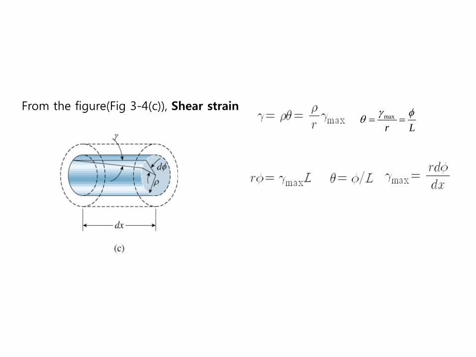
From the figure(Fig 3-4(c)), Shear strain max
r Lγ φθ = =
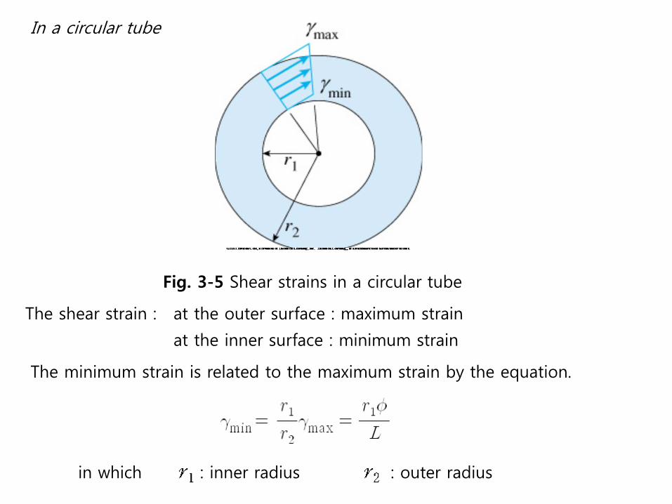
In a circular tube
Fig. 3-5 Shear strains in a circular tube
The shear strain : at the outer surface : maximum strain
at the inner surface : minimum strain
The minimum strain is related to the maximum strain by the equation.
in which : inner radius : outer radius

3.3 Circular Bars of Linearly Elastic Materials
We have investigated the shear strain.
We have to determine the directions and magnitude of shear stresses.
The direction of the stresses can be determined by inspection
Fig. 3-6 Shear stresses in a circular bar in torsion

The magnitudes of the shear stresses can be determined from the stress-strain relation for the material of the bar.
From
∴
: shear stress at the outer surface of the bar(radius )
: shear stress at an interior point (radius )
: the rate of twist
( has units of radians per unit of length)
max maxGτ γ=

Fig. 3-7 Longitudinal and transverse shear stresses in a circular bar subjected to torsion
Fig. 3-8 Tensile and compressive stresses acting on a stress element oriented at 45° to the longitudinal axis.
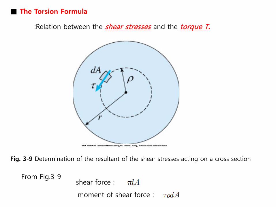
■ The Torsion Formula
:Relation between the shear stresses and the torque T.
Fig. 3-9 Determination of the resultant of the shear stresses acting on a cross section
From Fig.3-9 shear force :
moment of shear force :

From( )
Elemental moment
resultant moment(T)
in which
: polar moment of inertia
※For a circle of radius and diameter , the polar moment of inertia is
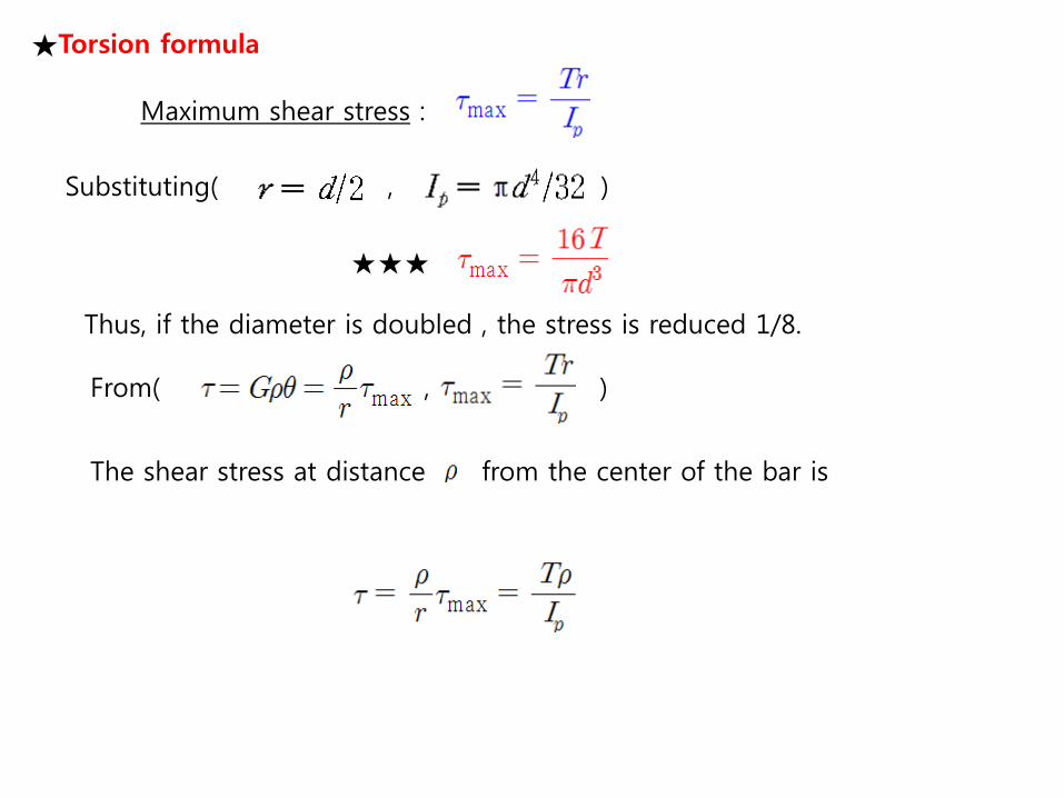
★Torsion formula
Maximum shear stress :
Substituting( , )
★★★
Thus, if the diameter is doubled , the stress is reduced 1/8.
From( , )
The shear stress at distance from the center of the bar is
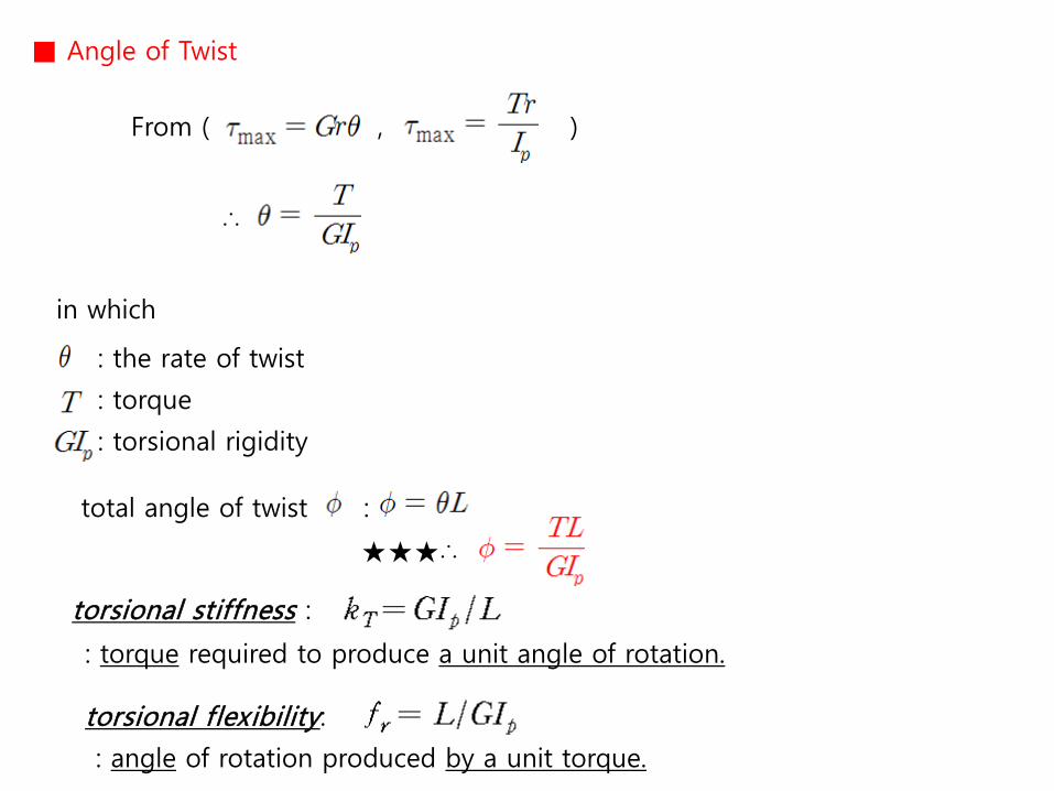
■ Angle of Twist
From ( , )
∴
in which
: the rate of twist
: torque
: torsional rigidity
total angle of twist :
★★★∴
torsional stiffness :
: torque required to produce a unit angle of rotation.
torsional flexibility:
: angle of rotation produced by a unit torque.

■ Circular Tubes
: The analysis of the torsion of circular tube is almost identical to that for a solid bar.
Fig. 3-10 Circular tube in torsion
polar moment of inertia of the cross-sectional area of a tube :
The preceding expressions can also be written in the following form:
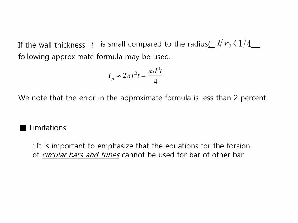
If the wall thickness is small compared to the radius(
following approximate formula may be used.
We note that the error in the approximate formula is less than 2 percent.
■ Limitations
: It is important to emphasize that the equations for the torsion of circular bars and tubes cannot be used for bar of other bar.
332
4pd tI r t ππ≈ =

■ Example 3-1 A solid steel bar of circular section has diameter d=1.5 in., length L=54 in., and shear modulus of elasticity psi. The bar is subject to torques T acting at the ends.
©2001 Brooks/Cole, a division of Thomson Learning, Inc. Thomson Learning™ is a trademark used herein under license.©2001 Brooks/Cole, a division of Thomson Learning, Inc. Thomson Learning™ is a trademark used herein under license.
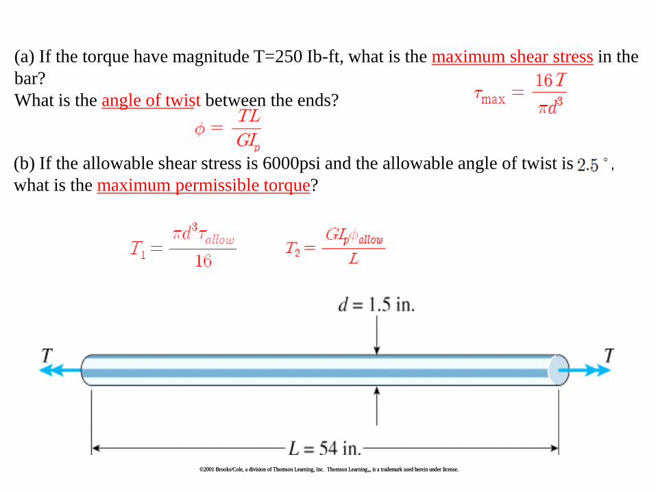
(a) If the torque have magnitude T=250 Ib-ft, what is the maximum shear stress in the bar? What is the angle of twist between the ends?
(b) If the allowable shear stress is 6000psi and the allowable angle of twist is , what is the maximum permissible torque?
©2001 Brooks/Cole, a division of Thomson Learning, Inc. Thomson Learning™ is a trademark used herein under license.©2001 Brooks/Cole, a division of Thomson Learning, Inc. Thomson Learning™ is a trademark used herein under license.

Solution (a) maximum shear stress and angle of twist. Because the bar has a solid circular cross section, we can find the maximum shear stress
from Eq.(3-12)( ), as follows:
In a similar manner, the angle of twist is obtained from Eq.(3-15) with the polar moment of inertia given by Eq.(3-15):
Thus, the analysis of the bar under the action of the given torque is completed.
1 12ft in=
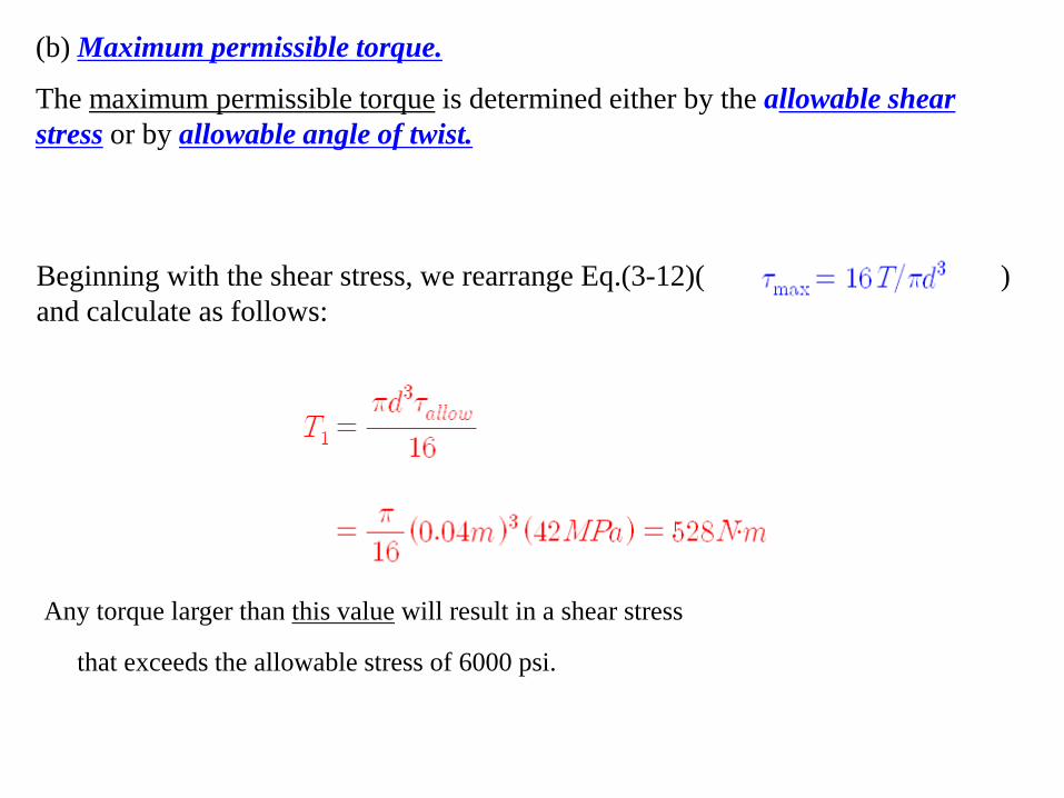
(b) Maximum permissible torque.
The maximum permissible torque is determined either by the allowable shear stress or by allowable angle of twist.
Beginning with the shear stress, we rearrange Eq.(3-12)( ) and calculate as follows:
Any torque larger than this value will result in a shear stress
that exceeds the allowable stress of 6000 psi.
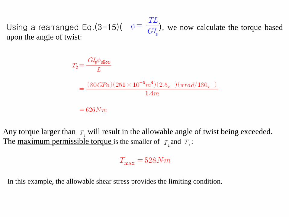
Using a rearranged Eq.(3-15)( ), we now calculate the torque based upon the angle of twist:
Any torque larger than will result in the allowable angle of twist being exceeded.
The maximum permissible torque is the smaller of and :
In this example, the allowable shear stress provides the limiting condition.
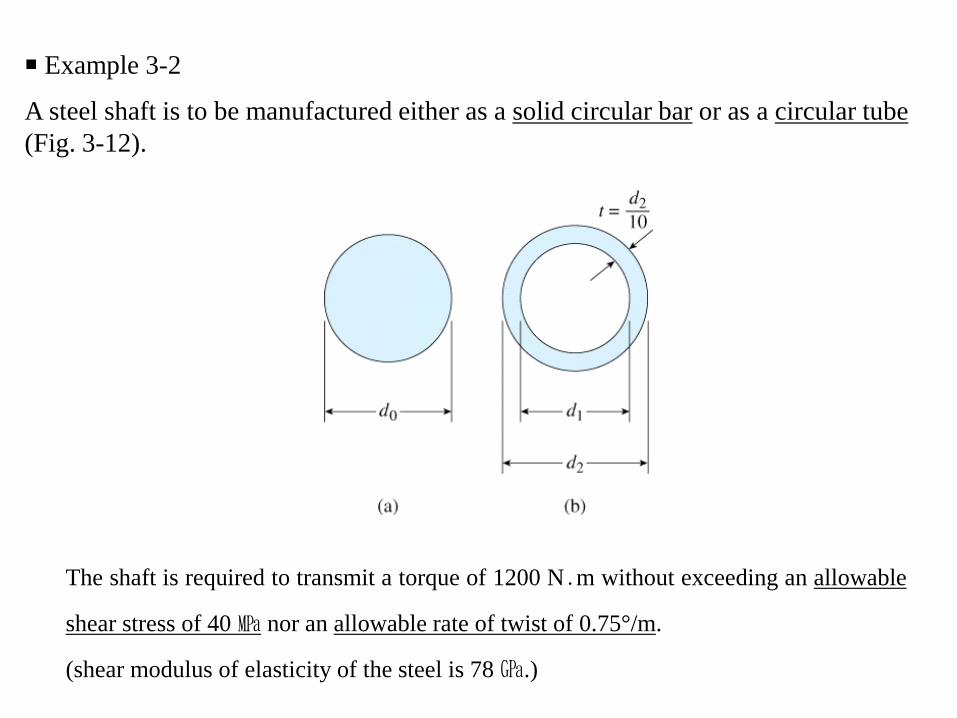
■ Example 3-2
A steel shaft is to be manufactured either as a solid circular bar or as a circular tube (Fig. 3-12).
The shaft is required to transmit a torque of 1200 N․m without exceeding an allowable
shear stress of 40 ㎫ nor an allowable rate of twist of 0.75°/m.
(shear modulus of elasticity of the steel is 78 ㎬.)
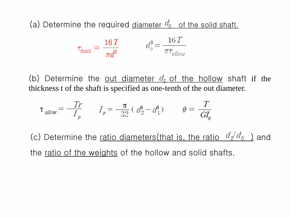
(a) Determine the required diameter of the solid shaft.
(b) Determine the out diameter of the hollow shaft if the thickness t of the shaft is specified as one-tenth of the out diameter.
(c) Determine the ratio diameters(that is, the ratio ) and
the ratio of the weights of the hollow and solid shafts.

(a) solid shaft. The required diameter is determined either from the allowable shear stress or from the allowable rate of twist. (1) In the case of the allowable shear we rearrange Eq.(3-12)( ) and obtain
from which we get
Solution
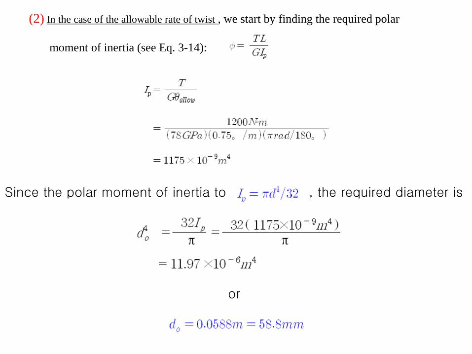
(2) In the case of the allowable rate of twist , we start by finding the required polar moment of inertia (see Eq. 3-14):
Since the polar moment of inertia to , the required diameter is
or

Comparing the two values of , we see that the rate of twist governs the design and the required diameter of the solid shaft is
In a practical design, we would select a diameter slightly larger than the calculated value of ; for instance, 60㎜ (b) Hollow shaft. Again, the required diameter is based upon either the allowable shear stress or the allowable rate of twist. We begin by nothing that the outer diameter of the bar is and the inner diameter is

Thus, the polar moment of inertia (Eq. 3-16) is
(1) In the case of the allowable shear stress, we use the torsion formula(Eq. 3-11)( ) as follows:

Rearranging, we get
Solving for gives
which is the required outer diameter based upon the shear stress.

(2) In the case of the allowable rate twist, we use Eq.(3-14)( ) with replaced by and replaced by the previously obtained expression; thus, from which
Solving for gives
which is the required diameter based upon the rate of twist.
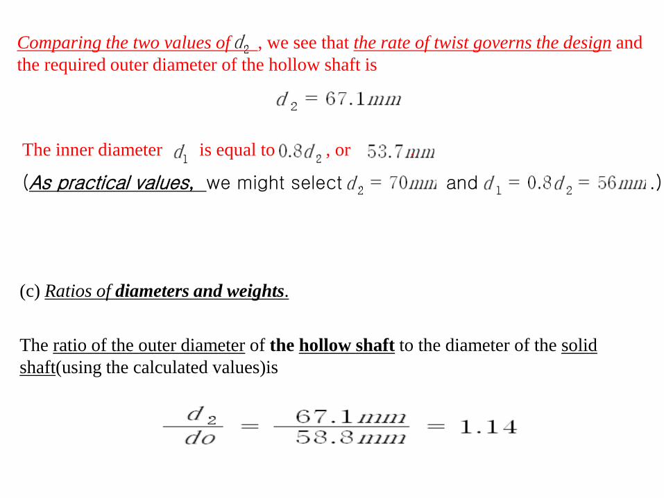
Comparing the two values of , we see that the rate of twist governs the design and the required outer diameter of the hollow shaft is
The inner diameter is equal to , or .
(As practical values, we might select and .)
(c) Ratios of diameters and weights.
The ratio of the outer diameter of the hollow shaft to the diameter of the solid shaft(using the calculated values)is

Since the weight of the shafts are proportional to their cross-sectional areas, we can express the ratio of the weight of the hollow shaft to the weight of the solid shaft as follows:
These results show that
the hollow shaft uses only 47% as much material as does the solid shaft, while its
outer diameter is only 14% larger.
Note: This example illustrates how to determine the required sizes of both solid bars
and circular tubes when allowable stresses and allowable rates of twist are known.
It also illustrates the fact circular tubes are more efficient in the use of materials than
are solid circular bars.
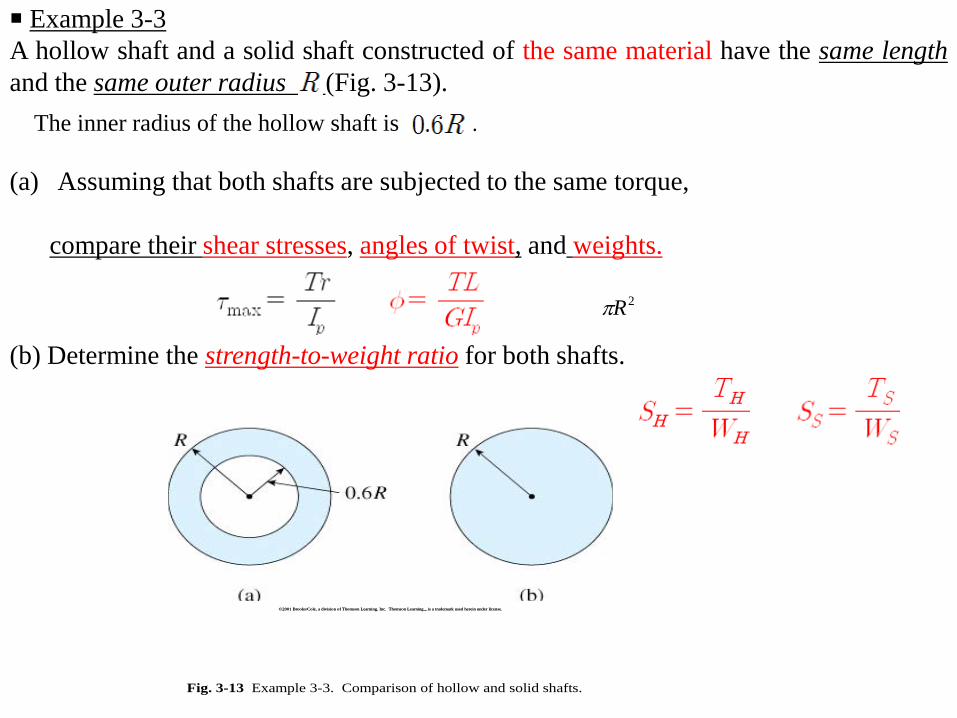
■ Example 3-3 A hollow shaft and a solid shaft constructed of the same material have the same length and the same outer radius (Fig. 3-13).
(a) Assuming that both shafts are subjected to the same torque, compare their shear stresses, angles of twist, and weights.
(b) Determine the strength-to-weight ratio for both shafts.
©2001 Brooks/Cole, a division of Thomson Learning, Inc. Thomson Learning™ is a trademark used herein under license.©2001 Brooks/Cole, a division of Thomson Learning, Inc. Thomson Learning™ is a trademark used herein under license.
Fig. 3-13 Example 3-3. Comparison of hollow and solid shafts.
The inner radius of the hollow shaft is .
2Rπ
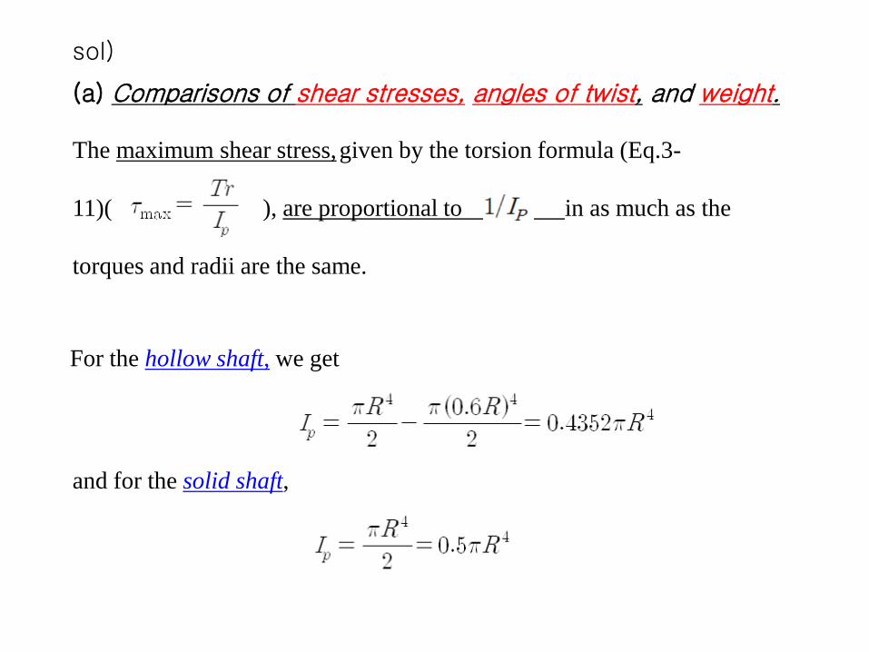
sol)
(a) Comparisons of shear stresses, angles of twist, and weight. The maximum shear stress, given by the torsion formula (Eq.3- 11)( ), are proportional to in as much as the torques and radii are the same.
For the hollow shaft, we get
and for the solid shaft,
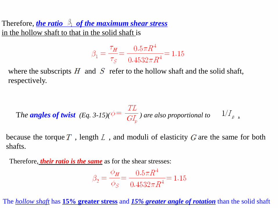
Therefore, the ratio of the maximum shear stress in the hollow shaft to that in the solid shaft is
where the subscripts and refer to the hollow shaft and the solid shaft, respectively.
The angles of twist (Eq. 3-15)( ) are also proportional to ,
because the torque , length , and moduli of elasticity are the same for both shafts.
Therefore, their ratio is the same as for the shear stresses:
The hollow shaft has 15% greater stress and 15% greater angle of rotation than the solid shaft
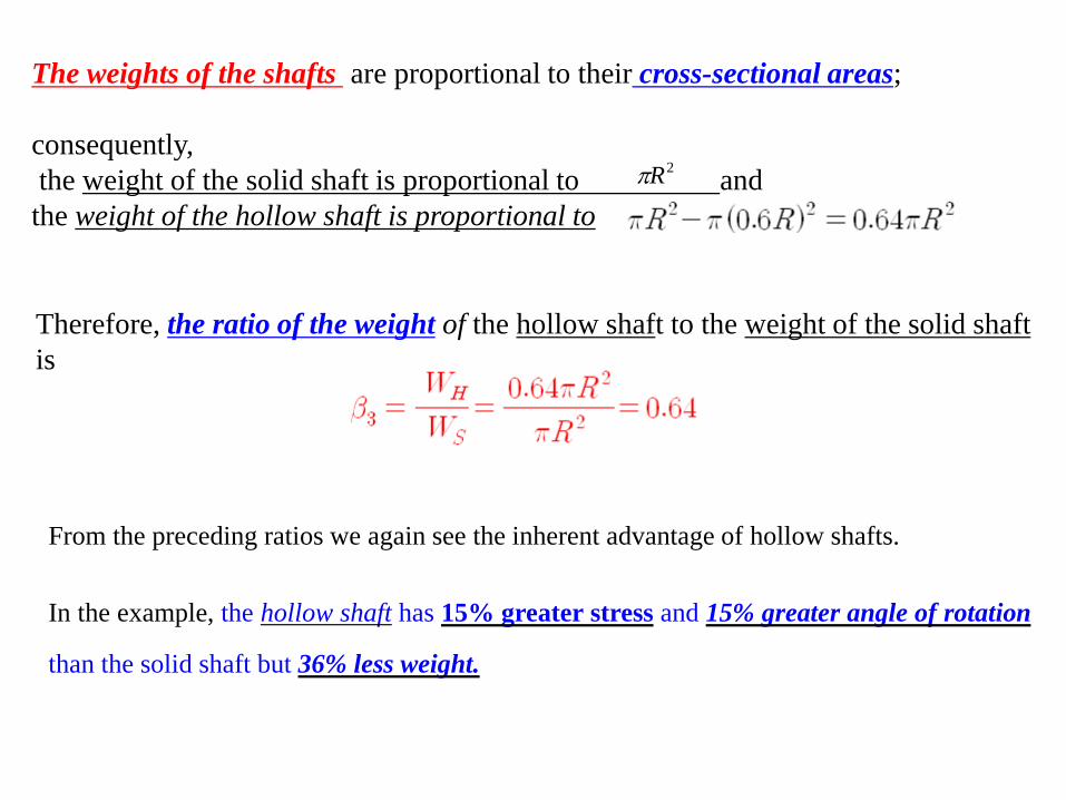
The weights of the shafts are proportional to their cross-sectional areas; consequently, the weight of the solid shaft is proportional to and the weight of the hollow shaft is proportional to
Therefore, the ratio of the weight of the hollow shaft to the weight of the solid shaft is
From the preceding ratios we again see the inherent advantage of hollow shafts.
In the example, the hollow shaft has 15% greater stress and 15% greater angle of rotation
than the solid shaft but 36% less weight.
2Rπ
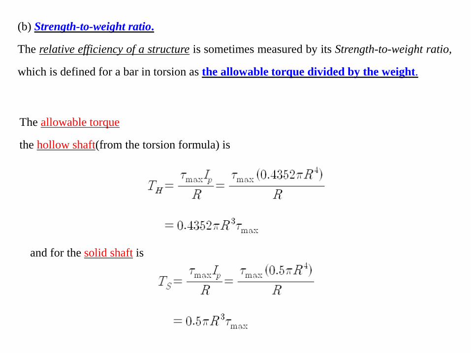
(b) Strength-to-weight ratio.
The relative efficiency of a structure is sometimes measured by its Strength-to-weight ratio,
which is defined for a bar in torsion as the allowable torque divided by the weight.
The allowable torque
the hollow shaft(from the torsion formula) is
and for the solid shaft is
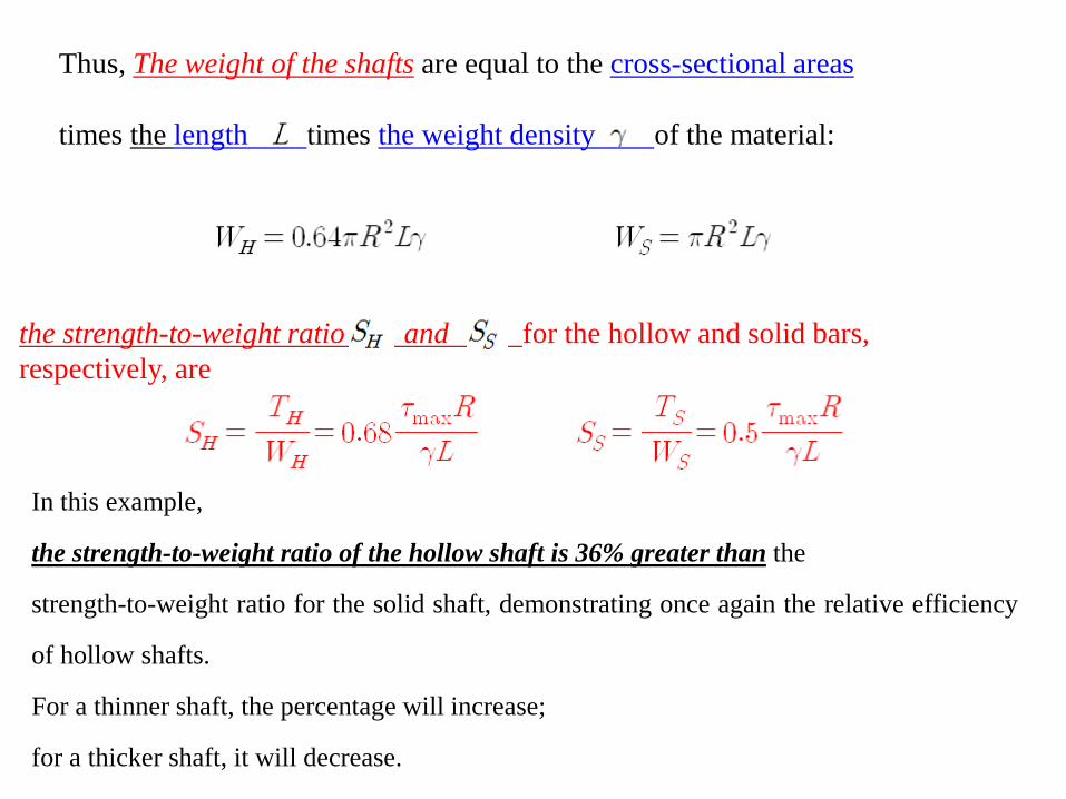
Thus, The weight of the shafts are equal to the cross-sectional areas times the length times the weight density of the material:
the strength-to-weight ratio and for the hollow and solid bars, respectively, are
In this example,
the strength-to-weight ratio of the hollow shaft is 36% greater than the
strength-to-weight ratio for the solid shaft, demonstrating once again the relative efficiency
of hollow shafts.
For a thinner shaft, the percentage will increase;
for a thicker shaft, it will decrease.
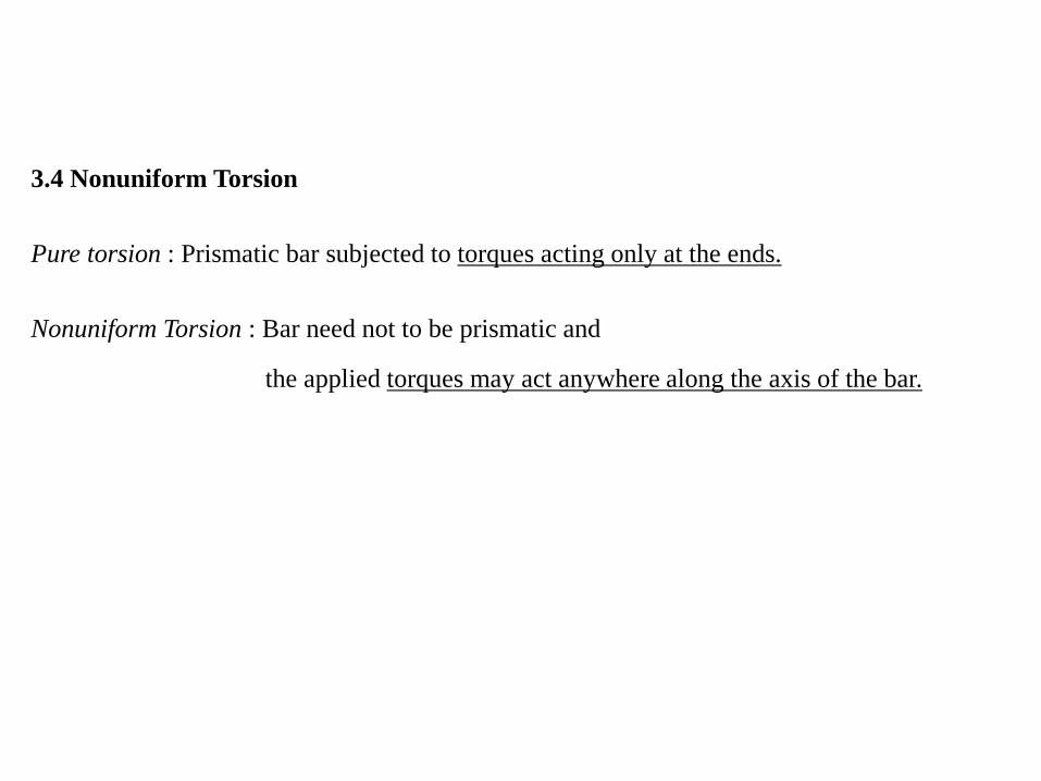
3.4 Nonuniform Torsion
Pure torsion : Prismatic bar subjected to torques acting only at the ends.
Nonuniform Torsion : Bar need not to be prismatic and
the applied torques may act anywhere along the axis of the bar.

Case 1. Bar consisting of prismatic segments with constant torque throughout each
segment
Fig. 3-14 Bar in nonuniform torsion (Case 1)

Torque : From fig.3-14(b)
From fig.3-14(c)
From fig.3-14(d)
angle of twist
∴

Case 2. Bar with continuously varying cross sections and constant torque.
Fig. 3-15 Bar in nonuniform torsion (Case 2)
We consider an element of length at distance from one end of the bar(fig.3.15)
differential angle of rotation :
For the entire :

Case 3. Bar with continuously varying cross sections and continuously varying torque.
Fig. 3-16 Bar in nonuniform torsion (Case 3)
angle of twist :
■ Limitation
1) linearly elastic material
2) The changes in diameter are small and gradual.
(The formula are satisfactory as long as the angle
of taper is less than 10°)
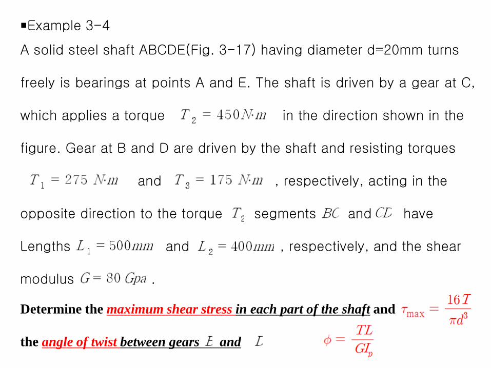
■Example 3-4 A solid steel shaft ABCDE(Fig. 3-17) having diameter d=20mm turns freely is bearings at points A and E. The shaft is driven by a gear at C, which applies a torque in the direction shown in the figure. Gear at B and D are driven by the shaft and resisting torques and , respectively, acting in the opposite direction to the torque segments and have Lengths and , respectively, and the shear modulus .
Determine the maximum shear stress in each part of the shaft and the angle of twist between gears and

©2001 Brooks/Cole, a division of Thomson Learning, Inc. Thomson Learning™ is a trademark used herein under license.©2001 Brooks/Cole, a division of Thomson Learning, Inc. Thomson Learning™ is a trademark used herein under license.
Fig. 3-17 Example 3-4. Steel shaft in torsion.

©2001 Brooks/Cole, a division of Thomson Learning, Inc. Thomson Learning™ is a trademark used herein under license.©2001 Brooks/Cole, a division of Thomson Learning, Inc. Thomson Learning™ is a trademark used herein under license.
Fig. 3-18 Free-body diagrams for Example 3-4.

Solution
Torque acting in the segments.
The torques and angle of the twist in the end segment(AB and DE) are 0
? from (fig 3-18(b))
Fig. 3-1 Example
? from (fig 3-18(a))
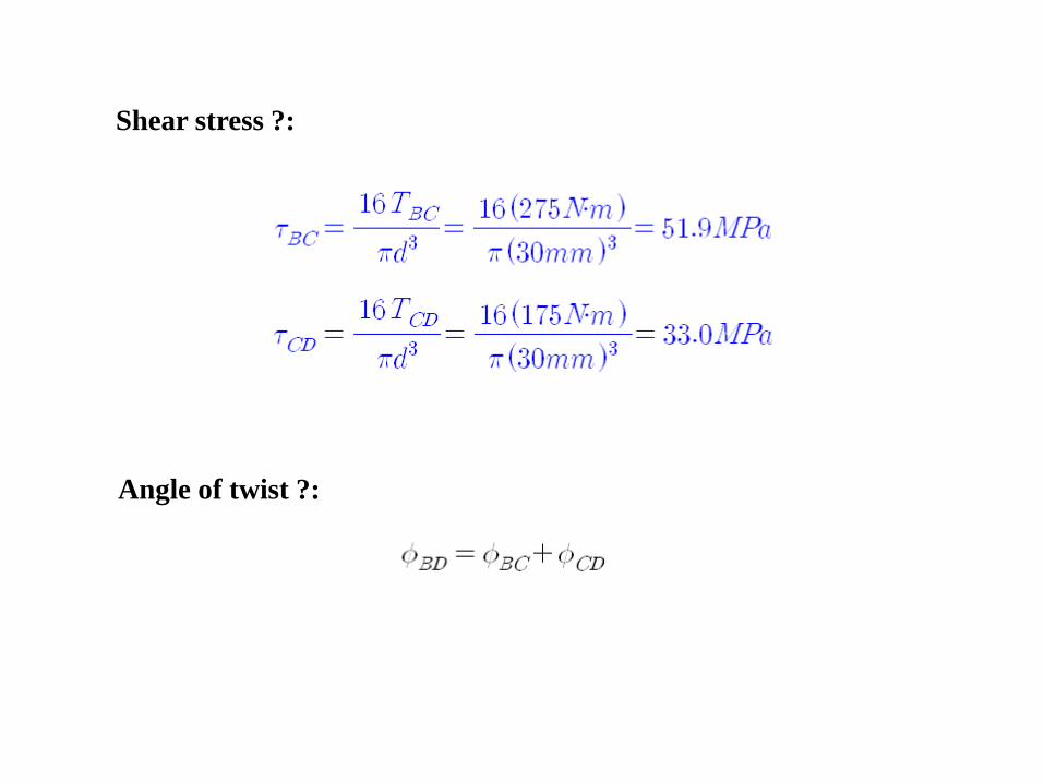
Shear stress ?:
Angle of twist ?:

( )
∴
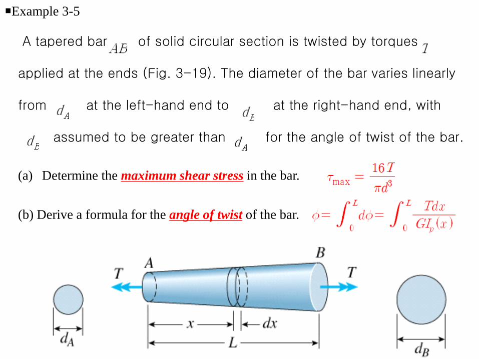
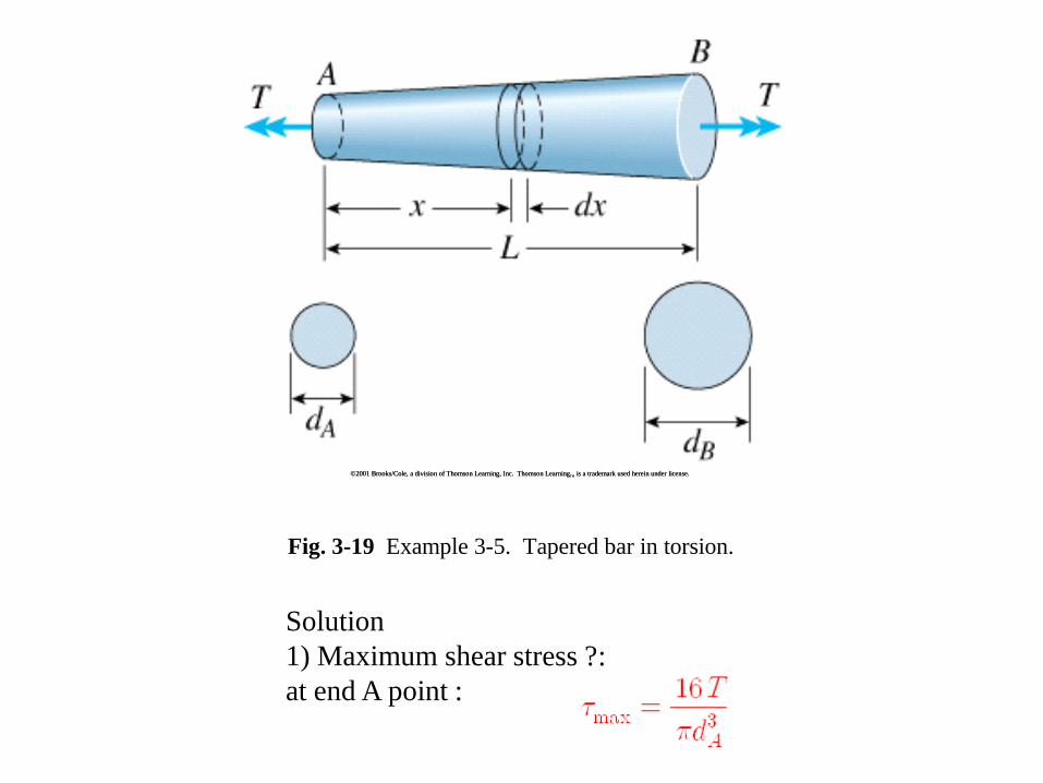
■Example 3-5
A tapered bar of solid circular section is twisted by torques applied at the ends (Fig. 3-19). The diameter of the bar varies linearly from at the left-hand end to at the right-hand end, with assumed to be greater than for the angle of twist of the bar.
(a) Determine the maximum shear stress in the bar.
(b) Derive a formula for the angle of twist of the bar.
©2001 Brooks/Cole, a division of Thomson Learning, Inc. Thomson Learning™ is a trademark used herein under license.©2001 Brooks/Cole, a division of Thomson Learning, Inc. Thomson Learning™ is a trademark used herein under license.
Fig. 3-19 Example 3-5. Tapered bar in torsion.
Solution 1) Maximum shear stress ?: at end A point :
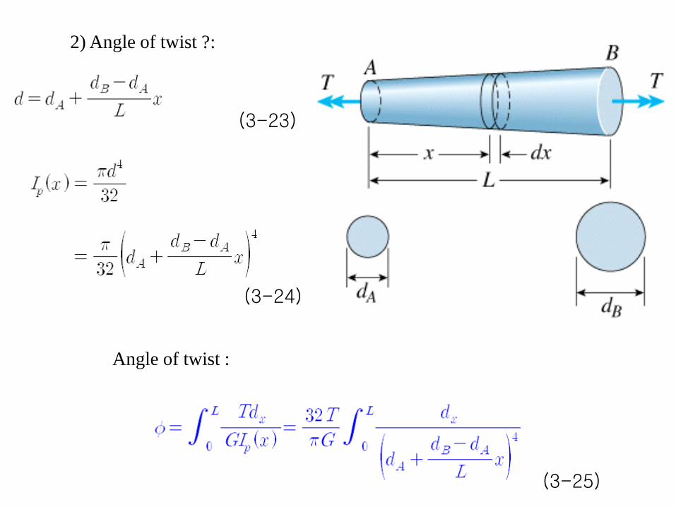
2) Angle of twist ?:
(3-23)
Angle of twist :
(3-25)
(3-24)

in which
(e,f)
,
(g) ∴
Thus, the integral in Eq.3-25 equals
(g)
From (3-25)
(3-26)
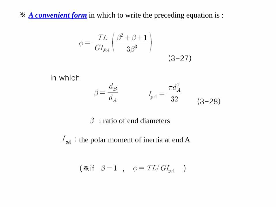
※ A convenient form in which to write the preceding equation is :
(3-27)
(3-28)
: ratio of end diameters
: the polar moment of inertia at end A
(※if , )
in which