
Chapter II-2 Construction – Fire protection, fire ...unina.stidue.net/Universita' di...
132
Chapter II-2 - Construction – Fire protection, fire detection and fire extinction 163 Chapter II-2 - Construction – Fire protection, fire detection and fire extinction
Transcript of Chapter II-2 Construction – Fire protection, fire ...unina.stidue.net/Universita' di...
Chapter II-2 - Construction – Fire protection, fire detection and fire extinction
Chapter II-2-Construction – Fire protection, fire detection and fire extinction
163
Chapter II-2
Part A - General
Part A-General
Regulation 1Application
1 Application
1.1 Unless expressly provided otherwise, this chapter shall apply to ships constructed on or after 1July 2002.
1.2 For the purpose of this chapter:
.1 the expression ships constructed means ships the keels of which are laid or which are at asimilar stage of construction;
.2 the expression all ships means ships, irrespective of type, constructed before, on or after 1July 2002; and
.3 a cargo ship, whenever built, which is converted to a passenger ship shall be treated as apassenger ship constructed on the date on which such a conversion commences.
1.3 For the purpose of this chapter, the expression a similar stage of construction means the stage atwhich:
.1 construction identifiable with a specific ship begins; and
.2 assembly of that ship has commenced comprising at least 50 tonnes or one per cent ofthe estimated mass of all structural material, whichever is less.
2 Applicable requirements to existing ships
2.1 Unless expressly provided otherwise, for ships constructed before 1 July 2002 the Administra-tion shall ensure that the requirements which are applicable under chapter II-2 of the InternationalConvention for the Safety of Life at Sea, 1974, as amended by resolutions MSC.1(XLV), MSC.6(48),MSC.13(57), MSC.22(59), MSC.24(60), MSC.27(61), MSC.31(63) and MSC.57(67), are complied with.
2.2 Ships constructed before 1 July 2002 shall also comply with:
.1 paragraphs 3, 6.5 and 6.7 as appropriate;
164
Chapter II-2
Part A - General
.2 regulations 13.3.4.2 to 13.3.4.5, 13.4.3 and Part E, except regulations 16.3.2.2 and16.3.2.3 thereof, as appropriate, not later than the date of the first survey after 1 July2002;
.3 regulations 10.4.1.3 and 10.6.4 for new installations only; and
.4 regulation 10.5.6 not later than 1 October 2005 for passenger ships of 2,000 gross ton-nage and above.
3 Repairs, alterations, modifications and outfitting
3.1 All ships which undergo repairs, alterations, modifications and outfitting related thereto shallcontinue to comply with at least the requirements previously applicable to these ships. Such ships, ifconstructed before 1 July 2002, shall, as a rule, comply with the requirements for ships constructed onor after that date to at least the same extent as they did before undergoing such repairs, alterations,modifications or outfitting.
3.2 Repairs, alterations and modifications which substantially alter the dimensions of a ship or thepassenger accommodation spaces, or substantially increase a ship's service life and outfitting relatedthereto shall meet the requirements for ships constructed on or after 1 July 2002 in so far as the Admin-istration deems reasonable and practicable.
4 Exemptions
4.1 The Administration of a State may, if it considers that the sheltered nature and conditions of thevoyage are such as to render the application of any specific requirements of this chapter unreasonable
or unnecessary, exempt* from those requirements individual ships or classes of ships entitled to fly theflag of that State which, in the course of their voyage, do not proceed more than 20 miles from the near-est land.
4.2 In the case of passenger ships which are employed in special trades for the carriage of largenumbers of special trade passengers, such as the pilgrim trade, the Administration, if satisfied that it isimpracticable to enforce compliance with the requirements of this chapter, may exempt such ships fromthose requirements, provided that they comply fully with the provisions of:
.1 the rules annexed to the Special Trade Passenger Ships Agreement, 1971 ; and
.2 the rules annexed to the Protocol on Space Requirements for Special Trade PassengerShips, 1973.
* Refer to port State concurrence with SOLAS exemptions (MSC/Circ.606).
165
Chapter II-2
Part A - General
5 Applicable requirements depending on ship type
Unless expressly provided otherwise:
.1 requirements not referring to a specific ship type shall apply to ships of all types; and
.2 requirements referring to "tankers" shall apply to tankers subject to the requirements spec-ified in paragraph 6 below.
6 Application of requirements for tankers
6.1 Requirements for tankers in this chapter shall apply to tankers carrying crude oil or petroleumproducts having a flashpoint not exceeding 60oC (closed cup test), as determined by an approved flash-point apparatus, and a Reid vapour pressure which is below the atmospheric pressure or other liquidproducts having a similar fire hazard.
6.2 Where liquid cargoes other than those referred to in paragraph 6.1 or liquefied gases whichintroduce additional fire hazards are intended to be carried, additional safety measures shall berequired, having due regard to the provisions of the International Bulk Chemical Code, as defined inregulation VII/8.1, the Bulk Chemical Code, the International Gas Carrier Code, as defined in regulationVII/11.1, and the Gas Carrier Code, as appropriate.
6.2.1 A liquid cargo with a flashpoint of less than 60ºC for which a regular foam firefighting systemcomplying with the Fire Safety Systems Code is not effective, is considered to be a cargo introducingadditional fire hazards in this context. The following additional measures are required:
.1 the foam shall be of alcohol resistant type;
.2 the type of foam concentrates for use in chemical tankers shall be to the satisfaction of the
Administration taking into account the guidelines developed by the Organization;* and
.3 the capacity and application rates of the foam extinguishing system shall comply withchapter 11 of the International Bulk Chemical Code, except that lower application ratesmay be accepted based on performance tests. For tankers fitted with inert gas systems, a
quantity of foam concentrate sufficient for 20 min of foam generation may be accepted.**
6.2.2 For the purpose of this regulation, a liquid cargo with a vapour pressure greater than 1.013 barabsolute at 37.8°C is considered to be a cargo introducing additional fire hazards. Ships carrying suchsubstances shall comply with paragraph 15.14 of the International Bulk Chemical Code. When shipsoperate in restricted areas and at restricted times, the Administration concerned may agree to waive the
* Refer to the Guidelines for performance and testing criteria and surveys of expansion foam concentrates for fire-extinguishingsystems for chemical tankers (MSC/Circ.799).** Refer to the Information on flashpoint and recommended fire-fighting media for chemicals to which neither the IBC nor BCHCodes apply (MSC/Circ.553).
166
Chapter II-2
Part A - General
requirements for refrigeration systems in accordance with paragraph 15.14.3 of the International BulkChemical Code.
6.3 Liquid cargoes with a flashpoint exceeding 60ºC other than oil products or liquid cargoes sub-ject to the requirements of the International Bulk Chemical Code are considered to constitute a low firerisk, not requiring the protection of a fixed foam extinguishing system.
6.4 Tankers carrying petroleum products with a flashpoint exceeding 60oC (closed cup test), asdetermined by an approved flashpoint apparatus, shall comply with the requirements provided in regu-lations 10.2.1.4.4. and 10.10.2.3 and the requirements for cargo ships other than tankers, except that,in lieu of the fixed fire extinguishing system required in regulation 10.7, they shall be fitted with a fixeddeck foam system which shall comply with the provisions of the Fire Safety Systems Code.
6.5 Combination carriers constructed before, on or after 1 July 2002 shall not carry cargoes otherthan oil unless all cargo spaces are empty of oil and gas-freed or unless the arrangements provided ineach case have been be approved by the Administration taking into account the guidelines developed
by the Organization*.
6.6 Chemical tankers and gas carriers shall comply with the requirements for tankers, exceptwhere alternative and supplementary arrangements are provided to the satisfaction of the Administra-tion, having due regard to the provisions of the International Bulk Chemical Code and the InternationalGas Carrier Code, as appropriate.
6.7 The requirements of regulations 4.5.10.1.1 and 4.5.10.1.4, and a system for continuous moni-toring of the concentration of hydrocarbon gases shall be fitted on all tankers constructed before 1 July2002 by the date of the first scheduled dry-docking after 1 July 2002, but not later than 1 July 2005.Sampling points or detector heads shall be located in suitable positions in order that potentially danger-ous leakages are readily detected. When the hydrocarbon gas concentration reaches a pre-set levelwhich shall not be higher than 10% of the lower flammable limit, a continuous audible and visualalarm signal shall be automatically effected in the pump-room and cargo control room to alert person-nel to the potential hazard. However, existing monitoring systems already fitted having a pre-set levelnot greater than 30% of the lower flammable limit may be accepted.
Regulation 2Fire safety objectives and functional requirements
1 Fire safety objectives
1.1 The fire safety objectives of this chapter are to:
.1 prevent the occurrence of fire and explosion;
* Refer to the Guidelines for inert gas systems (MSC/Circ.353), as amended by MSC/Circ.387.
167
Chapter II-2
Part A - General
.2 reduce the risk to life caused by fire;
.3 reduce the risk of damage caused by fire to the ship, its cargo and the environment;
.4 contain, control and suppress fire and explosion in the compartment of origin; and
.5 provide adequate and readily accessible means of escape for passengers and crew.
2 Functional requirements
2.1 In order to achieve the fire safety objectives set out in paragraph 1 above, the following func-tional requirements are embodied in the regulations of this chapter as appropriate:
.1 division of the ship into main vertical and horizontal zones by thermal and structuralboundaries;
.2 separation of accommodation spaces from the remainder of the ship by thermal andstructural boundaries;
.3 restricted use of combustible materials;
.4 detection of any fire in the zone of origin;
.5 containment and extinction of any fire in the space of origin;
.6 protection of means of escape and access for fire-fighting;
.7 ready availability of fire-extinguishing appliances; and
.8 minimization of possibility of ignition of flammable cargo vapour.
3 Achievement of the fire safety objectives
The fire safety objectives set out in paragraph 1 above shall be achieved by ensuring compliance withthe prescriptive requirements specified in parts B, C, D, E or G, or by alternative design and arrange-ments which comply with Part F. A ship shall be considered to meet the functional requirements set outin paragraph 2 and to achieve the fire safety objectives set out in paragraph 1 when either:
.1 the ship’s designs and arrangements, as a whole, complies with the relevant prescriptiverequirements in parts B, C, D, E or G;
.2 the ship’s designs and arrangements, as a whole, have been reviewed and approved inaccordance with part F; or
168
Chapter II-2
Part A - General
.3 part(s) of the ship’s designs and arrangements have been reviewed and approved inaccordance with part F and the remaining parts of the ship comply with the rele vant pre-scriptive requirements in parts B, C, D, E or G.
Regulation 3Definitions
For the purpose of this chapter, unless expressly provided otherwise, the following definitions shallapply:
1 Accommodation spaces are those spaces used for public spaces, corridors, lavatories, cabins,offices, hospitals, cinemas, game and hobby rooms, barber shops, pantries containing no cookingappliances and similar spaces;
2 "A" class divisions are those divisions formed by bulkheads and decks which comply with thefollowing criteria:
.1 they are constructed of steel or other equivalent material;
.2 they are suitably stiffened;
.3 they are insulated with approved non-combustible materials such that the average tem-perature of the unexposed side will not rise more than 140ºC above the originaltemperature, nor will the temperature, at any one point, including any joint, rise morethan 180ºC above the original temperature, within the time listed below:
class "A-60" 60 min
class "A-30" 30 min
class "A-15" 15 min
class "A-0" 0 min
.4 they are constructed as to be capable of preventing the passage of smoke and flame to theend of the one-hour standard fire test; and
.5 the Administration has required a test of a prototype bulkhead or deck in accordancewith the Fire Test Procedures Code to ensure that it meets the above requirements forintegrity and temperature rise.
3 Atriums are public spaces within a single main vertical zone spanning three or more opendecks.
169
Chapter II-2
Part A - General
4 "B" class divisions are those divisions formed by bulkheads, decks, ceilings or linings whichcomply with the following criteria:
.1 they are constructed of approved non-combustible materials and all materials used in theconstruction and erection of "B" class divisions are non-combustible, with the exceptionthat combustible veneers may be permitted provided they meet other appropriate require-ments of this chapter;
.2 they have an insulation value such that the average temperature of the unexposed sidewill not rise more than 140ºC above the original temperature, nor will the temperature atany one point, including any joint, rise more than 225ºC above the original temperature,within the time listed below:
class "B-15" 15 min
class "B-0" 0 min
.3 they are constructed as to be capable of preventing the passage of flame to the end of thefirst half hour of the standard fire test; and
.4 the Administration has required a test of a prototype division in accordance with the FireTest Procedures Code to ensure that it meets the above requirements for integrity andtemperature rise.
5 Bulkhead deck is the uppermost deck up to which the transverse watertight bulkheads arecarried.
6 Cargo area is that part of the ship that contains cargo holds, cargo tanks, slop tanks and cargopump-rooms including pump-rooms, cofferdams, ballast and void spaces adjacent to cargo tanks andalso deck areas throughout the entire length and breadth of the part of the ship over the above-men-tioned spaces.
7 Cargo ship is a ship as defined in regulation I/2(g).
8 Cargo spaces are spaces used for cargo, cargo oil tanks, tanks for other liquid cargo and trunksto such spaces.
9 Central control station is a control station in which the following control and indicator func-tions are centralized:
.1 fixed fire detection and fire alarm systems;
170

Chapter II-2
Part A - General
.2 automatic sprinkler, fire detection and fire alarm systems;
.3 fire door indicator panels;
.4 fire door closure;
.5 watertight door indicator panels;
.6 watertight door closures;
.7 ventilation fans;
.8 general/fire alarms;
.9 communication systems including telephones; and
.10 microphones to public address systems.
10 "C" class divisions are divisions constructed of approved non-combustible materials. Theyneed meet neither requirements relative to the passage of smoke and flame nor limitations relative tothe temperature rise. Combustible veneers are permitted provided they meet the requirements of thischapter.
11 Chemical tanker is a cargo ship constructed or adapted and used for the carriage in bulk of anyliquid product of a flammable nature listed in chapter 17 of the International Bulk Chemical Code, asdefined in regulation VII/8.1.
12 Closed ro-ro spaces are ro-ro spaces which are neither open ro-ro spaces nor weather decks.
13 Closed vehicle spaces are vehicle spaces which are neither open vehicle spaces nor weatherdecks.
14 Combination carrier is a cargo ship designed to carry both oil and solid cargoes in bulk.
15 Combustible material is any material other than a non-combustible material.
16 Continuous "B" class ceilings or linings are those "B" class ceilings or linings which terminate atan "A" or "B" class division.
171
Chapter II-2
Part A - General
17 Continuously manned central control station is a central control station which is continuouslymanned by a responsible member of the crew.
18 Control stations are those spaces in which the ship’s radio or main navigating equipment or theemergency source of power is located or where the fire recording or fire control equipment is central-ized. Spaces where the fire recording or fire control equipment is centralized are also considered to bea fire control station.
19 Crude oil is any oil occurring naturally in the earth whether or not treated to render it suitablefor transportation and includes crude oil where certain distillate fractions may have been removed fromor added to.
20 Dangerous goods are those goods referred to in regulation VII/2.
21 Deadweight is the difference in tonnes between the displacement of a ship in water of a spe-cific gravity of 1.025 at the load waterline corresponding to the assigned summer freeboard and thelightweight of the ship.
22 Fire Safety Systems Code means the International Code for Fire Safety Systems as adopted bythe Maritime Safety Committee of the Organization by resolution MSC.98(73), as may be amended bythe Organization, provided that such amendments are adopted, brought into force and take effect inaccordance with the provisions of article VIII of the present Convention concerning the amendmentprocedures applicable to the annex other than chapter I thereof.
23 Fire Test Procedures Code means the International Code for Application of Fire Test Proceduresas adopted by the Maritime Safety Committee of the Organization by resolution MSC.61(67), as may beamended by the Organization, provided that such amendments are adopted, brought into force andtake effect in accordance with the provisions of article VIII of the present Convention concerning theamendment procedures applicable to the annex other than chapter I thereof.
24 Flashpoint is the temperature in degrees Celsius (closed cup test) at which a product will giveoff enough flammable vapour to be ignited, as determined by an approved flashpoint apparatus.
25 Gas carrier is a cargo ship constructed or adapted and used for the carriage in bulk of any liq-uefied gas or other products of a flammable nature listed in chapter 19 of the International Gas CarrierCode, as defined in regulation VII/11.1.
172
Chapter II-2
Part A - General
26 Helideck is a purpose-built helicopter landing area located on a ship including all structure,fire-fighting appliances and other equipment necessary for the safe operation of helicopters.
27 Helicopter facility is a helideck including any refuelling and hangar facilities.
28 Lightweight is the displacement of a ship in tonnes without cargo, fuel, lubricating oil, ballastwater, fresh water and feedwater in tanks, consumable stores, and passengers and crew and theireffects.
29 Low flame-spread means that the surface thus described will adequately restrict the spread offlame, this being determined in accordance with the Fire Test Procedures Code.
30 Machinery spaces are machinery spaces of category A and other spaces containing propulsionmachinery, boilers, oil fuel units, steam and internal combustion engines, generators and major electri-cal machinery, oil filling stations, refrigerating, stabilizing, ventilation and air conditioning machinery,and similar spaces, and trunks to such spaces.
31 Machinery spaces of category A are those spaces and trunks to such spaces which containeither:
.1 internal combustion machinery used for main propulsion;
.2 internal combustion machinery used for purposes other than main propulsion where suchmachinery has in the aggregate a total power output of not less than 375 kW; or
.3 any oil-fired boiler or oil fuel unit, or any oil-fired equipment other thanboilers, such as inert gas generators, incinerators, etc.
32 Main vertical zones are those sections into which the hull, superstructure and deckhouses aredivided by "A" class divisions, the mean length and width of which on any deck does not in generalexceed 40 m.
33 Non-combustible material is a material which neither burns nor gives off flammable vapours insufficient quantity for self-ignition when heated to approximately 750oC, this being determined inaccordance with the Fire Test Procedures Code.
173
Chapter II-2
Part A - General
34 Oil fuel unit is the equipment used for the preparation of oil fuel for delivery to an oilfiredboiler, or equipment used for the preparation for delivery of heated oil to an internal combustionengine, and includes any oil pressure pumps, filters and heaters dealing with oil at a pressure of morethan 0.18 N/mm2.
35 Open ro-ro spaces are those ro-ro spaces that are either open at both ends or have an openingat one end, and are provided with adequate natural ventilation effective over their entire length throughpermanent openings distributed in the side plating or deckhead or from above, having a total area of atleast 10% of the total area of the space sides.
36 Open vehicle spaces are those vehicle spaces either open at both ends, or have an opening atone end and are provided with adequate natural ventilation effective over their entire length throughpermanent openings distributed in the side plating or deckhead or from above, having a total area of atleast 10% of the total area of the space sides.
37 Passenger ship is a ship as defined in regulation I/2(f).
38 Prescriptive requirements means the construction characteristics, limiting dimensions, or firesafety systems specified in parts B, C, D, E or G.
39 Public spaces are those portions of the accommodation which are used for halls, dining rooms,lounges and similar permanently enclosed spaces.
40 Rooms containing furniture and furnishings of restricted fire risk, for the purpose of regulation9, are those rooms containing furniture and furnishings of restricted fire risk (whether cabins, publicspaces, offices or other types of accommodation) in which:
.1 case furniture such as desks, wardrobes, dressing tables, bureaux, dressers, are con-structed entirely of approved non-combustible materials, except that a combustibleveneer not exceeding 2 mm may be used on the working surface of such articles;
.2 free-standing furniture such as chairs, sofas, tables, are constructed with frames of non-combustible materials;
.3 draperies, curtains and other suspended textile materials have qualities of resistance tothe propagation of flame not inferior to those of wool having a mass of mass 0.8 kg/m2,this being determined in accordance with the Fire Test Procedures Code;
.4 floor coverings have low flame-spread characteristics;
174

Chapter II-2
Part A - General
.5 exposed surfaces of bulkheads, linings and ceilings have low flame-spreadcharacteristics;
.6 upholstered furniture has qualities of resistance to the ignition and propagation of flame,this being determined in accordance with the Fire Test Procedures Code; and
.7 bedding components have qualities of resistance to the ignition and propagation of flame,this being determined in accordance with the Fire Test Procedures Code.
41 Ro-ro spaces are spaces not normally subdivided in any way and normally extending to eithera substantial length or the entire length of the ship in which motor vehicles with fuel in their tanks fortheir own propulsion and/or goods (packaged or in bulk, in or on rail or road cars, vehicles (includingroad or rail tankers), trailers, containers, pallets, demountable tanks or in or on similar stowage units orother receptacles) can be loaded and unloaded normally in a horizontal direction.
42 Ro-ro passenger ship means a passenger ship with ro-ro spaces or special category spaces.
43 Steel or other equivalent material means any non-combustible material which, by itself or dueto insulation provided, has structural and integrity properties equivalent to steel at the end of the appli-cable exposure to the standard fire test (e.g. aluminium alloy with appropriate insulation).
44 Sauna is a hot room with temperatures normally varying between 80º-120ºC where the heat isprovided by a hot surface (e.g. by an electrically-heated oven). The hot room may also include thespace where the oven is located and adjacent bathrooms.
45 Service spaces are those spaces used for galleys, pantries containing cooking appliances, lock-ers, mail and specie rooms, storerooms, workshops other than those forming part of the machineryspaces, and similar spaces and trunks to such spaces.
46 Special category spaces are those enclosed vehicle spaces above and below the bulkheaddeck, into and from which vehicles can be driven and to which passengers have access. Special cate-gory spaces may be accommodated on more than one deck provided that the total overall clear heightfor vehicles does not exceed 10 m.
47 A standard fire test is a test in which specimens of the relevant bulkheads or decks are exposedin a test furnace to temperatures corresponding approximately to the standard timetemperature curve inaccordance with the test method specified in the Fire Test Procedures Code.
175

Chapter II-2
Part A - General
48 Tanker is a ship as defined in regulation I/2(h).
49 Vehicle spaces are cargo spaces intended for carriage of motor vehicles with fuel in their tanksfor their own propulsion.
50 Weather deck is a deck which is completely exposed to the weather from above and from atleast two sides.
176
Chapter II-2
Part B - Prevention Of Fire And Explosion
Part B-Prevention Of Fire And Explosion
Regulation 4Probability of ignition
1 Purpose
The purpose of this regulation is to prevent the ignition of combustible materials or flammable liquids.For this purpose, the following functional requirements shall be met:
.1 means shall be provided to control leaks of flammable liquids;
.2 means shall be provided to limit the accumulation of flammable vapours;
.3 the ignitability of combustible materials shall be restricted;
.4 ignition sources shall be restricted;
.5 ignition sources shall be separated from combustible materials and flammable liquids;and
.6 the atmosphere in cargo tanks shall be maintained out of the explosive range.
2 Arrangements for oil fuel, lubrication oil and other flammable oils
2.1 Limitations in the use of oils as fuel
The following limitations shall apply to the use of oil as fuel:
.1 except as otherwise permitted by this paragraph, no oil fuel with a flashpoint of less than
60ºC shall be used;*
.2 in emergency generators oil fuel with a flashpoint of not less than 43ºC may be used;
.3 the use of oil fuel having a flashpoint of less than 60ºC but not less than 43ºC may be per-mitted (e.g., for feeding the emergency fire pump’s engines and the auxiliary machineswhich are not located in the machinery spaces of category A) subject to the following:
* Refer to the Recommended procedures to prevent the illegal or accidental use of low flashpoint cargo oil as fuel adopted bythe Organization by resolution A.565(14).
177
Chapter II-2
Part B - Prevention Of Fire And Explosion
.3.1 fuel oil tanks except those arranged in double bottom compartments shall be locatedoutside of machinery spaces of category A;
.3.2 provisions for the measurement of oil temperature are provided on the suction pipeof the oil fuel pump;
.3.3 stop valves and/or cocks are provided on the inlet side and outlet side of the oil fuelstrainers; and
.3.4 pipe joints of welded construction or of circular cone type or spherical type unionjoint are applied as much as possible; and
.4 in cargo ships the use of fuel having a lower flashpoint than otherwise specified in para-graph 2.1, for example crude oil, may be permitted provided that such fuel is not storedin any machinery space and subject to the approval by the Administration of the com-plete installation.
2.2 Arrangements for oil fuel
In a ship in which oil fuel is used, the arrangements for the storage, distribution and utilization of the oilfuel shall be such as to ensure the safety of the ship and persons on board and shall at least comply withthe following provisions.
2.2.1 Location of oil fuel systems
As far as practicable, parts of the oil fuel system containing heated oil under pressure exceeding 0.18 N/mm2 shall not be placed in a concealed position such that defects and leakage cannot readily beobserved. The machinery spaces in way of such parts of the oil fuel system shall be adequatelyilluminated.
2.2.2 Ventilation of machinery spaces
The ventilation of machinery spaces shall be sufficient under normal conditions to preventaccumula-tion of oil vapour.
2.2.3 Oil fuel tanks
2.2.3.1 Fuel oil, lubrication oil and other flammable oils shall not be carried in forepeaktanks.
2.2.3.2 As far as practicable, oil fuel tanks shall be part of the ships structure and shall belocated out-side machinery spaces of category A. Where oil fuel tanks, other than doublebottom tanks, arenecessarily located adjacent to or within machinery spaces of category A, atleast one of their verticalsides shall be contiguous to the machinery space boundaries, andshall preferably have a commonboundary with the double bottom tanks, and the area of thetank boundary common with the machineryspaces shall be kept to a minimum. Where suchtanks are situated within the boundaries of machinery
178

Chapter II-2
Part B - Prevention Of Fire And Explosion
spaces of category A they shall notcontain oil fuel having a flashpoint of less than 60ºC. In general, theuse of free-standing oilfuel tanks shall be avoided. When such tanks are employed their use shall beprohibited incategory A machinery spaces on passenger ships. Where permitted, they shall be placed inanoil-tight spill tray of ample size having a suitable drain pipe leading to a suitably sized spilloil tank.
2.2.3.3 No oil fuel tank shall be situated where spillage or leakage therefrom can constitute a fire orexplosion hazard by falling on heated surfaces.
2.2.3.4 Oil fuel pipes, which, if damaged, would allow oil to escape from a storage, settlingor dailyservice tank having a capacity of 500 l and above situated above the double bottom,shall be fitted witha cock or valve directly on the tank capable of being closed from a safeposition outside the space con-cerned in the event of a fire occurring in the space in whichsuch tanks are situated. In the special caseof deep tanks situated in any shaft or pipe tunnelor similar space, valves on the tank shall be fitted, butcontrol in the event of fire may beeffected by means of an additional valve on the pipe or pipes outsidethe tunnel or similarspace. If such an additional valve is fitted in the machinery space it shall be oper-ated from aposition outside this space. The controls for remote operation of the valve for theemergencygenerator fuel tank shall be in a separate location from the controls for remote operationofother valves for tanks located in machinery spaces.
2.2.3.5 Safe and efficient means of ascertaining the amount of oil fuel contained in any oil fuel tankshall be provided.
2.2.3.5.1 Where sounding pipes are used, they shall not terminate in any space where the risk of igni-tion of spillage from the sounding pipe might arise. In particular, they shall not terminate in passengeror crew spaces. As a general rule, they shall not terminate in machinery spaces. However, where theAdministration considers that these latter requirements are impracticable, it may permit termination ofsounding pipes in machinery spaces on condition that all of the following requirements are met:
.1 an oil-level gauge is provided meeting the requirements of paragraph 2.2.3.5.2;
.2 the sounding pipes terminate in locations remote from ignition hazards unless precau-tions are taken, such as the fitting of effective screens, to prevent the oil fuel in the case ofspillage through the terminations of the sounding pipes from coming into contact with asource of ignition; and
.3 the termination of sounding pipes are fitted with self-closing blanking devices and with asmall-diameter self-closing control cock located below the blanking device for the pur-pose of ascertaining before the blanking device is opened that oil fuel is not present.Provisions shall be made so as to ensure that any spillage of oil fuel through the controlcock involves no ignition hazard.
2.2.3.5.2 Other oil-level gauges may be used in place of sounding pipes subject to the followingconditions:
.1 in passenger ships, such gauges shall not require penetration below the top of the tankand their failure or overfilling of the tanks shall not permit release of fuel; and
179
Chapter II-2
Part B - Prevention Of Fire And Explosion
.2 in cargo ships, the failure of such gauges or overfilling of the tank shall not permit releaseof fuel into the space. The use of cylindrical gauge glasses is prohibited. The Administra-tion may permit the use of oil-level gauges with flat glasses and self-closing valvesbetween the gauges and fuel tanks.
2.2.3.5.3 The means prescribed in paragraph 2.2.3.5.2 which are acceptable to the Administrationshall be maintained in the proper condition to ensure their continued accurate functioning in service.
2.2.4 Prevention of overpressureProvisions shall be made to prevent overpressure in any oil tank or in any part of the oil fuelsystem,including the filling pipes served by pumps on board. Air and overflow pipes andrelief valves shall dis-charge to a position where there is no risk of fire or explosion from theemergence of oils and vapourand shall not lead into crew spaces, passenger spaces nor intospecial category spaces, closed ro-rocargo spaces, machinery spaces or similar spaces.
2.2.5 Oil fuel piping
2.2.5.1 Oil fuel pipes and their valves and fittings shall be of steel or other approved material, exceptthat restricted use of flexible pipes shall be permissible in positions where the Administration is satisfied
that they are necessary.* Such flexible pipes and end attachments shall be of approved fire-resistingmaterials of adequate strength and shall be constructed to the satisfaction of the Administration. Forvalves, fitted to oil fuel tanks and which are under static pressure, steel or spheroidal-graphite cast ironmay be accepted. However, ordinary cast iron valves may be used in piping systems where the designpressure is lower than 7 bar and the design temperature is below 60ºC.
2.2.5.2 External high-pressure fuel delivery lines between the high-pressure fuel pumps and fuel injec-tors shall be protected with a jacketed piping system capable of containing fuel from a high-pressureline failure. A jacketed pipe incorporates an outer pipe into which the high-pressure fuel pipe is placed,forming a permanent assembly. The jacketed piping system shall include a means for collection of leak-ages and arrangements shall be provided with an alarm in case of a fuel line failure.
2.2.5.3 Oil fuel lines shall not be located immediately above or near units of high temperature includ-ing boilers, steam pipelines, exhaust manifolds, silencers or other equipment required to be insulatedby paragraph 2.2.6. As far as practicable, oil fuel lines shall be arranged far apart from hot surfaces,electrical installations or other sources of ignition and shall be screened or otherwise suitably protectedto avoid oil spray or oil leakage onto the sources of ignition. The number of joints in such piping sys-tems shall be kept to a minimum.
2.2.5.4 Components of a diesel engine fuel system shall be designed considering themaximum peakpressure which will be experienced in service, including any high pressurepulses which are generatedand transmitted back into the fuel supply and spill lines by theaction of fuel injection pumps. Connec-tions within the fuel supply and spill lines shall beconstructed having regard to their ability to preventpressurized oil fuel leaks while in serviceand after maintenance.
* Refer to recommendations published by the International Organization for Standardization, in particular, Publications ISO15540:1999 on Test methods for fire resistance of hose assemblies and ISO 15541:1999 on Requirements for the test bench offire resistance of hose assemblies.
180

Chapter II-2
Part B - Prevention Of Fire And Explosion
2.2.5.5 In multi-engine installations which are supplied from the same fuel source, means of isolatingthe fuel supply and spill piping to individual engines, shall be provided. The means of isolation shallnot affect the operation of the other engines and shall be operable from a position not rendered inac-cessible by a fire on any of the engines.
2.2.5.6 Where the Administration may permit the conveying of oil and combustible liquids throughaccommodation and service spaces, the pipes conveying oil or combustible liquids shall be of a mate-rial approved by the Administration having regard to the fire risk.
2.2.6 Protection of high temperature surfaces
2.2.6.1 Surfaces with temperatures above 220°C which may be impinged as a result of a fuelsystemfailure shall be properly insulated.
2.2.6.2 Precautions shall be taken to prevent any oil that may escape under pressure from anypump,filter or heater from coming into contact with heated surfaces.
2.3 Arrangements for lubricating oil
2.3.1 The arrangements for the storage, distribution and utilization of oil used in pressurelubricationsystems shall be such as to ensure the safety of the ship and persons on board.The arrangements madein machinery spaces of category A, and whenever practicable inother machinery spaces, shall at leastcomply with the provisions of paragraphs 2.2.1, 2.2.3.3,2.2.3.4, 2.2.3.5, 2.2.4, 2.2.5.1, 2.2.5.3 and2.2.6, except that:
.1 this does not preclude the use of sight-flow glasses in lubricating systems provided thatthey are shown by testing to have a suitable degree of fire resistance; and
.2 sounding pipes may be authorized in machinery spaces; however, therequirements ofparagraphs 2.2.3.5.1.1 and 2.2.3.5.1.3 need not be applied oncondition that the sound-ing pipes are fitted with appropriate means of closure.
2.3.2 The provisions of paragraph 2.2.3.4 shall also apply to lubricating oil tanks exceptthose havinga capacity less than 500 l, storage tanks on which valves are closed during thenormal operation modeof the ship, or where it is determined that an unintended operation ofa quick closing valve on the oillubricating tank would endanger the safe operation of themain propulsion and essential auxiliarymachinery.
2.4 Arrangements for other flammable oils
The arrangements for the storage, distribution and utilization of other flammable oilsemployed underpressure in power transmission systems, control and activating systems andheating systems shall besuch as to ensure the safety of the ship and persons on board.Suitable oil collecting arrangements forleaks shall be fitted below hydraulic valves andcylinders. In locations where means of ignition arepresent, such arrangements shall at leastcomply with the provisions of paragraphs 2.2.3.3, 2.2.3.5,
181
Chapter II-2
Part B - Prevention Of Fire And Explosion
2.2.5.3 and 2.2.6 and with theprovisions of paragraphs 2.2.4 and 2.2.5.1 in respect of strength andconstruction.
2.5 Arrangements for oil fuel in periodically unattended machinery spaces
In addition to the requirements of paragraphs 2.1 to 2.4, the oil fuel and lubricating oilsystems in a peri-odically unattended machinery space shall comply with the following:
.1 where daily service oil fuel tanks are filled automatically, or by remote control, meansshall be provided to prevent overflow spillages. Other equipment which treats flammableliquids automatically (e.g. oil fuel purifiers) which, whenever practicable, shall beinstalled in a special space reserved for purifiers and their heaters, shall have arrange-ments to prevent overflow spillages; and
.2 where daily service oil fuel tanks or settling tanks are fitted with heating arrangements, ahigh temperature alarm shall be provided if the flashpoint of the oil fuel can be exceeded.
3 Arrangements for gaseous fuel for domestic purpose
Gaseous fuel systems used for domestic purposes shall be approved by the Administration.Storage ofgas bottles shall be located on the open deck or in a well ventilated space whichopens only to the opendeck.
4 Miscellaneous items of ignition sources and ignitability
4.1 Electric radiators
Electric radiators, if used, shall be fixed in position and so constructed as to reduce fire risksto a mini-mum. No such radiators shall be fitted with an element so exposed that clothing,curtains, or othersimilar materials can be scorched or set on fire by heat from the element.
4.2 Waste receptacles
Waste receptacles shall be constructed of non-combustible materials with no openings in thesides orbottom.
4.3 Insulation surfaces protected against oil penetration
In spaces where penetration of oil products is possible, the surface of insulation shall beimpervious tooil or oil vapours.
182
Chapter II-2
Part B - Prevention Of Fire And Explosion
4.4 Primary deck coverings
Primary deck coverings, if applied within accommodation and service spaces and controlstations, shallbe of approved material which will not readily ignite, this being determined inaccordance with the FireTest Procedures Code.
5 Cargo areas of tankers
5.1 Separation of cargo oil tanks
5.1.1 Cargo pump-rooms, cargo tanks, slop tanks and cofferdams shall be positionedforward ofmachinery spaces. However, oil fuel bunker tanks need not be forward ofmachinery spaces. Cargotanks and slop tanks shall be isolated from machinery spaces bycofferdams, cargo pump-rooms, oilbunker tanks or ballast tanks. Pump-rooms containingpumps and their accessories for ballasting thosespaces situated adjacent to cargo tanks andslop tanks and pumps for oil fuel transfer, shall be consid-ered as equivalent to a cargopump-room within the context of this regulation provided that such pump-rooms have thesame safety standard as that required for cargo pump-rooms. Pump-rooms intendedsolely forballast or oil fuel transfer, however, need not comply with the requirements of regulation 10.9.The lower portion of the pump-room may be recessed into machinery spaces ofcategory A to accom-modate pumps, provided that the deck head of the recess is in general notmore than one third of themoulded depth above the keel, except that in the case of ships ofnot more than 25,000 tonnes dead-weight, where it can be demonstrated that for reasons ofaccess and satisfactory piping arrangementsthis is impracticable, the Administration maypermit a recess in excess of such height, but not exceedingone half of the moulded depthabove the keel.
5.1.2 Main cargo control stations, control stations, accommodation and service spaces (excludingisolated cargo handling gear lockers) shall be positioned aft of cargo tanks, slop tanks, and spaceswhich isolate cargo or slop tanks from machinery spaces, but not necessarily aft of the oil fuel bunkertanks and ballast tanks, and shall be arranged in such a way that a single failure of a deck or bulkheadshall not permit the entry of gas or fumes from the cargo tanks into an accommodation space, maincargo control stations, control station, or service spaces. A recess provided in accordance with para-graph 5.1.1 need not be taken into account when the position of these spaces is being determined.
5.1.3 However, where deemed necessary, the Administration may permit main cargo controlstations,control stations, accommodation and service spaces forward of the cargo tanks, sloptanks and spaceswhich isolate cargo and slop tanks from machinery spaces, but notnecessarily forward of oil fuel bunkertanks or ballast tanks. Machinery spaces, other thanthose of category A, may be permitted forward ofthe cargo tanks and slop tanks providedthey are isolated from the cargo tanks and slop tanks by coffer-dams, cargo pump-rooms, oilfuel bunker tanks or ballast tanks, and have at least one portable fireextinguisher. In caseswhere they contain internal combustion machinery, one approved foam-typeextinguisher ofat least 45 l capacity or equivalent shall be arranged in addition to portable fire extin-guishers.If operation of a semi-portable fire extinguisher is impracticable, this fire extinguisher maybereplaced by two additional portable fire extinguishers. Accommodation spaces, main cargocontrolspaces, control stations and service spaces shall be arranged in such a way that asingle failure of a deckor bulkhead shall not permit the entry of gas or fumes from the cargotanks into such spaces. In addition,where deemed necessary for the safety or navigation ofthe ship, the Administration may permit machin-
183
Chapter II-2
Part B - Prevention Of Fire And Explosion
ery spaces containing internal combustionmachinery not being main propulsion machinery having anoutput greater than 375 kW to belocated forward of the cargo area provided the arrangements are inaccordance with theprovisions of this paragraph.
5.1.4 In combination carriers only:
.1 The slop tanks shall be surrounded by cofferdams except where theboundaries of the sloptanks, where slop may be carried on dry cargo voyages,are part of the hull, main cargodeck, cargo pump-room bulkhead or oil fuelbunker tank. These cofferdams shall not beopen to a double bottom, pipetunnel, pump-room or other enclosed space, nor shall theybe used for cargoor ballast and shall not be connected to piping systems serving oil cargoorballast. Means shall be provided for filling the cofferdams with water and fordrainingthem. Where the boundary of a slop tank is part of the cargopump-room bulkhead, thepump-room shall not be open to the double bottom,pipe tunnel or other enclosed space;however, openings provided with gastightbolted covers may be permitted;
.2 Means shall be provided for isolating the piping connecting the pump-roomwith the sloptanks referred to in paragraph 5.1.4.1. The means of isolationshall consist of a valve fol-lowed by a spectacle flange or a spool piece withappropriate blank flanges. Thisarrangement shall be located adjacent to theslop tanks, but where this is unreasonable orimpracticable, it may be locatedwithin the pump-room directly after the piping penetratesthe bulkhead. Aseparate permanently installed pumping and piping arrangement incor-poratinga manifold, provided with a shut-off valve and a blank flange, shall beprovidedfor discharging the contents of the slop tanks directly to the opendeck for disposal toshore reception facilities when the ship is in the drycargo mode. When the transfer sys-tem is used for slop transfer in the drycargo mode, it shall have no connection to othersystems. Separation fromother systems by means of removal of spool pieces may beaccepted;
.3 Hatches and tank cleaning openings to slop tanks shall only be permitted onthe opendeck and shall be fitted with closing arrangements. Except wherethey consist of boltedplates with bolts at watertight spacing, these closingarrangements shall be provided withlocking arrangements under the controlof the responsible ship’s officer; and
.4 Where cargo wing tanks are provided, cargo oil lines below deck shall beinstalled insidethese tanks. However, the Administration may permit cargooil lines to be placed in spe-cial ducts provided there are capable of beingadequately cleaned and ventilated to thesatisfaction of the Administration.Where cargo wing tanks are not provided, cargo oillines below deck shall beplaced in special ducts.
5.1.5 Where the fitting of a navigation position above the cargo area is shown to benecessary, it shallbe for navigation purposes only and it shall be separated from the cargotank deck by means of an openspace with a height of at least 2 m. The fire protectionrequirements for such a navigation position shallbe that required for control stations, asspecified in regulation 9.2.4.2 and other provisions for tankers,as applicable.
184
Chapter II-2
Part B - Prevention Of Fire And Explosion
5.1.6 Means shall be provided to keep deck spills away from the accommodation and service areas.This may be accomplished by provision of a permanent continuous coaming of a height of at least 300mm, extending from side to side. Specialconsideration shall be given to the arrangements associatedwith stern loading.
5.2 Restriction on boundary openings
5.2.1 Except as permitted in paragraph 5.2.2, access doors, air inlets and openings toaccommoda-tion spaces, service spaces, control stations and machinery spaces shall notface the cargo area. Theyshall be located on the transverse bulkhead not facing the cargoarea or on the outboard side of thesuperstructure or deckhouse at a distance of at least 4%of the length of the ship but not less than 3 mfrom the end of the superstructure ordeckhouse facing the cargo area. This distance need not exceed 5m.
5.2.2 The Administration may permit access doors in boundary bulkheads facing thecargo area orwithin the 5 m limits specified in paragraph 5.2.1, to main cargo controlstations and to such servicespaces used as provision rooms, store-rooms and lockers,provided they do not give access directly orindirectly to any other space containing orproviding for accommodation, control stations or servicespaces such as galleys, pantriesor workshops, or similar spaces containing sources of vapour ignition.The boundary ofsuch a space shall be insulated to "A-60" standard, with the exception of the boundary-facing the cargo area. Bolted plates for the removal of machinery may be fitted withinthe limitsspecified in paragraph 5.2.1. Wheelhouse doors and windows may be locatedwithin the limits speci-fied in paragraph 5.2.1 so long as they are designed to ensure thatthe wheelhouse can be made rapidlyand efficiently gas and vapour tight.
5.2.3 Windows and sidescuttles facing the cargo area and on the sides of thesuperstructures anddeckhouses within the limits specified in paragraph 5.2.1 shall be ofthe fixed (non-opening) type. Suchwindows and sidescuttles, except wheelhousewindows, shall be constructed to "A-60" class standard.
5.2.4 Where there is permanent access from a pipe tunnel to the main pump-room, a watertight doorshall be fitted complying with the requirements of regulation II-1/25-9.2 and, in addition, with thefollowing:
.1 in addition to the bridge operation, the watertight door shall be capable ofbeing manuallyclosed from outside the main pump-room entrance; and
.2 the watertight door shall be kept closed during normal operations of theship except whenaccess to the pipe tunnel is required.
5.2.5 Permanent approved gastight lighting enclosures for illuminating cargopump-rooms may bepermitted in bulkheads and decks separating cargo pump-rooms andother spaces provided they are ofadequate strength and the integrity and gastightness ofthe bulkhead or deck is maintained.
5.2.6 The arrangement of ventilation inlets and outlets and other deckhouse and superstructureboundary space openings shall be such as to complement the provisions of paragraph 5.3 and regula-tion 11.6. Such vents, especially for machinery spaces, shall be situated as far aft as practicable. Due
185
Chapter II-2
Part B - Prevention Of Fire And Explosion
consideration in this regard shall be given when the ship is equipped to load or discharge at the stern.Sources of ignition such as electrical equipment shall be so arranged as to avoid an explosion hazard.
5.3 Cargo tank venting
5.3.1 General requirements
The venting systems of cargo tanks are to be entirely distinct from the air pipes of the other compart-ments of the ship. The arrangements and position of openings in the cargo tank deck from whichemission of flammable vapours can occur shall be such as to minimize the possibility of flammablevapours being admitted to enclosed spaces containing a source of ignition, or collecting in the vicinityof deck machinery and equipment which may constitute an ignition hazard. In accordance with thisgeneral principle, the criteria in paragraphs 5.3.2 to 5.3.5 and regulation 11.6 will apply.
5.3.2 Venting arrangements
5.3.2.1 The venting arrangements in each cargo tank may be independent or combinedwith othercargo tanks and may be incorporated into the inert gas piping.
5.3.2.2 Where the arrangements are combined with other cargo tanks, either stop valvesor otheracceptable means shall be provided to isolate each cargo tank. Where stop valvesare fitted, they shallbe provided with locking arrangements which shall be under thecontrol of the responsible ship's officer.There shall be a clear visual indication of theoperational status of the valves or other acceptable means.Where tanks have beenisolated, it shall be ensured that relevant isolating valves are opened beforecargo loadingor ballasting or discharging of those tanks is commenced. Any isolation must continuetopermit the flow caused by thermal variations in a cargo tank in accordance withregulation 11.6.1.1.
5.3.2.3 If cargo loading and ballasting or discharging of a cargo tank or cargo tank groupis intended,which is isolated from a common venting system, that cargo tank or cargotank group shall be fitted witha means for over-pressure or under-pressure protection asrequired in regulation 11.6.3.2.
5.3.2.4 The venting arrangements shall be connected to the top of each cargo tank andshall be self-draining to the cargo tanks under all normal conditions of trim and list of theship. Where it may not bepossible to provide self-draining lines, permanentarrangements shall be provided to drain the vent linesto a cargo tank.
5.3.3 Safety devices in venting systems
The venting system shall be provided with devices to prevent the passage of flame into the cargo tanks.The design, testing and locating of these devices shall comply with the requirements established by the
Administration based on the guidelines developed by the Organization.* Ullage openings shall not beused for pressure equalization. They shall be provided with self-closing and tightly sealing covers.Flame arresters and screens are not permitted in these openings.
* Refer to MSC/Circ.677 on Revised standards for the design, testing and locating of devices to prevent the passage of flameinto cargo tanks in tankers and to MSC/Circ.450/Rev.1 on Revised factors to be taken into consideration when designing cargotank venting and gas-freeing arrangements.
186
Chapter II-2
Part B - Prevention Of Fire And Explosion
5.3.4 Vent outlets for cargo handling and ballasting
5.3.4.1 Vent outlets for cargo loading, discharging and ballasting required by regulation 11.6.1.2 shall:
.1.1 permit the free flow of vapour mixtures; or
.1.2 permit the throttling of the discharge of the vapour mixtures to achieve a velocity ofnot less than 30 m/s;
.2 be so arranged that the vapour mixture is discharged vertically upwards;
.3 where the method is by free flow of vapour mixtures, be such that the outletshall be notless than 6 m above the cargo tank deck or fore and aft gangwayif situated within 4 m ofthe gangway and located not less than 10 m measuredhorizontally from the nearest airintakes and openings to enclosed spacescontaining a source of ignition and from deckmachinery, which may includeanchor windlass and chain locker openings, and equip-ment which mayconstitute an ignition hazard; and
.4 where the method is by high-velocity discharge, be located at a height not lessthan 2 mabove the cargo tank deck and not less than 10 m measuredhorizontally from the nearestair intakes and openings to enclosed spacescontaining a source of ignition and from deckmachinery, which may includeanchor windlass and chain locker openings, and equip-ment which mayconstitute an ignition hazard. These outlets shall be provided withhighvelocity devices of an approved type.
5.3.4.2 The arrangements for the venting of vapours displaced from the cargo tanks duringloading andballasting shall comply with paragraph 5.3 and regulation 11.6 and shall consistof either one or moremast risers, or a number of high-velocity vents. The inert gas supplymain may be used for such venting.
5.3.5 Isolation of slop tanks in combination carriersIn combination carriers, the arrangements for isolating slop tanks containing oil or oilresidues fromother cargo tanks shall consist of blank flanges which will remain in position atall times when cargoesother than liquid cargoes referred to in regulation 1.6.1 are carried.
5.4 Ventilation
5.4.1 Ventilation systems in cargo pump-rooms
Cargo pump-rooms shall be mechanically ventilated and discharges from the exhaust fansshall be ledto a safe place on the open deck. The ventilation of these rooms shall havesufficient capacity to mini-mize the possibility of accumulation of flammable vapours. Thenumber of air changes shall be at least20 per hour, based upon the gross volume of the space.The air ducts shall be arranged so that all of thespace is effectively ventilated. Theventilation shall be of the suction type using fans of the non-sparkingtype.
187

Chapter II-2
Part B - Prevention Of Fire And Explosion
5.4.2 Ventilation systems in combination carriers
In combination carriers, cargo spaces and any enclosed spaces adjacent to cargo spaces shallbe capa-ble of being mechanically ventilated. The mechanical ventilation may be provided byportable fans. Anapproved fixed gas warning system capable of monitoring flammablevapours shall be provided in cargopump-rooms, pipe ducts and cofferdams, as referred to inparagraph 5.1.4, adjacent to slop tanks. Suita-ble arrangements shall be made to facilitatemeasurement of flammable vapours in all other spaceswithin the cargo area. Suchmeasurements shall be made possible from the open deck or easily accessi-ble positions.
5.5 Inert gas systems
5.5.1 Application
5.5.1.1 For tankers of 20,000 tonnes deadweight and upwards, the protection of the cargotanks shallbe achieved by a fixed inert gas system in accordance with the requirements ofthe Fire Safety SystemsCode, except that, in lieu of the above, the Administration, afterhaving given consideration to the ship’sarrangement and equipment, may accept other fixedinstallations if they afford protection equivalent tothe above, in accordance with regulationI/5. The requirements for alternative fixed installations shallcomply with the requirements inparagraph 5.5.4.
5.5.1.2 Tankers operating with a cargo tank cleaning procedure using crude oil washing shall be fittedwith an inert gas system complying with the Fire Safety Systems Code and with fixed tank washingmachines.
5.5.1.3 Tankers required to be fitted with inert gas systems shall comply with the following provisions:
.1 double hull spaces shall be fitted with suitable connections for the supply ofinert gas;
.2 where hull spaces are connected to a permanently fitted inert gas distributionsystem,means shall be provided to prevent hydrocarbon gases from the cargotanks entering thedouble hull spaces through the system; and
.3 where such spaces are not permanently connected to an inert gas distributionsystem,appropriate means shall be provided to allow connection to the inertgas main.
5.5.2 Inert gas systems of chemical tankers and gas carriers
The requirements for inert gas systems contained in the Fire Safety Systems Code need not beapplied to:
.1 chemical tankers and gas carriers when carrying cargoes described in regulation 1.6.1,provided that they comply with the requirements for inert gas systems on chemical tank-ers established by the Administration, based on the guidelines developed by the
Organization*; or
* Refer to the Regulation for inert gas systems on chemical tankers adopted by the Organization by resolution A.567(14) andCorr.1.
188
Chapter II-2
Part B - Prevention Of Fire And Explosion
.2 chemical tankers and gas carriers when carrying flammable cargoes other thancrude oilor petroleum products such as cargoes listed in chapters 17 and 18 ofthe InternationalBulk Chemical Code, provided that the capacity of tanksused for their carriage does notexceed 3,000 m3 and the individual nozzlecapacities of tank washing machines do notexceed 17.5 m3/h and the totalcombined throughput from the number of machines inuse in a cargo tank atany one time does not exceed 110 m3/h.
5.5.3 General requirements for inert gas systems
5.5.3.1 The inert gas system shall be capable of inerting, purging and gas-freeing emptytanks andmaintaining the atmosphere in cargo tanks with the required oxygen content.
5.5.3.2 The inert gas system referred to in paragraph 5.5.3.1 shall be designed, constructed and testedin accordance with the Fire Safety Systems Code.
5.5.3.3 Tankers fitted with a fixed inert gas system shall be provided with a closed ullage system.
5.5.4 Requirements for equivalent systems
5.5.4.1 Where an installation equivalent to a fixed inert gas system is installed, it shall:
.1 be capable of preventing dangerous accumulations of explosive mixtures in intact cargotanks during normal service throughout the ballast voyage and necessary in-tank opera-tions; and
.2 be so designed as to minimize the risk of ignition from the generation of static electricityby the system itself.
5.6 Inerting, purging and gas-freeing
5.6.1 Arrangements for purging and/or gas-freeing shall be such as to minimize the hazards due todispersal of flammable vapours in the atmosphere and to flammable mixtures in a cargo tank.
5.6.2 The procedure for cargo tank purging and/or gas-freeing shall be carried out inaccordance withregulation 16.3.2.
5.6.3 The arrangements for inerting, purging or gas-freeing of empty tanks as required inparagraph5.5.3.1 shall be to the satisfaction of the Administration and shall be such that theaccumulation ofhydrocarbon vapours in pockets formed by the internal structural members ina tank is minimized andthat:
.1 on individual cargo tanks, the gas outlet pipe, if fitted, shall be positioned asfar as practi-cable from the inert gas/air inlet and in accordance withparagraph 5.3 and regulation11.6. The inlet of such outlet pipes may belocated either at deck level or at not more than1 m above the bottom of the tank;
189
Chapter II-2
Part B - Prevention Of Fire And Explosion
.2 the cross-sectional area of such gas outlet pipe referred to in paragraph 5.6.3.1shall besuch that an exit velocity of at least 20 m/s can be maintained when any three tanks arebeing simultaneously supplied with inert gas. Their outlets shall extend not less than 2 mabove deck level; and
.3 each gas outlet referred to in paragraph 5.6.3.2 shall be fitted with suitable blankingarrangements.
5.7 Gas measurement
5.7.1 Portable instrument
Tankers shall be equipped with at least one portable instrument for measuring flammable vapour con-centrations, together with a sufficient set of spares. Suitable means shall be provided for the calibrationof such instruments.
5.7.2 Arrangements for gas measurement in double hull and double bottom spaces
5.7.2.1 Suitable portable instruments for measuring oxygen and flammable vapour concentrationsshall be provided. In selecting these instruments, due attention shall be given to their use in combina-tion with the fixed gas-sampling-line systems referred to in paragraph 5.7.2.2.
5.7.2.2 Where the atmosphere in double hull spaces cannot be reliably measured using flexible gassampling hoses, such spaces shall be fitted with permanent gas sampling lines. The configuration of gassampling lines shall be adapted to the design of such spaces.
5.7.2.3 The materials of construction and the dimensions of gas sampling lines shall be such as to pre-vent restriction. Where plastic materials are used, they shall be electrically conductive.
5.8 Air supply to double hull and double bottom spacesDouble hull and double bottom spaces shall be fitted with suitable connections for the supply of air.
5.9 Protection of cargo area
Drip pans for collecting cargo residues in cargo lines and hoses shall be provided in the area of pipeand hose connections under the manifold area. Cargo hoses and tank washing hoses shall have electri-cal continuity over their entire lengths including couplings and flanges (except shore connections) andshall be earthed for removal of electrostatic charges.
5.10 Protection of cargo pump-rooms
5.10.1 In tankers:
.1 cargo pumps, ballast pumps and stripping pumps, installed in cargo pumprooms anddriven by shafts passing through pump-room bulkheads shall be fitted with temperature
190

Chapter II-2
Part B - Prevention Of Fire And Explosion
sensing devices for bulkhead shaft glands, bearings and pump casings. A continuousaudible and visual alarm signal shall be automatically effected in the cargo control roomor the pump control station;
.2 lighting in cargo pump-rooms, except emergency lighting, shall be interlocked with ven-tilation such that the ventilation shall be in operation when switching on the lighting.Failure of the ventilation system shall not cause the lighting to go out;
.3 a system for continuous monitoring of the concentration of hydrocarbon gases shall be fit-ted. Sampling points or detector heads shall be located in suitable positions in order thatpotentially dangerous leakages are readily detected. When the hydrocarbon gas concen-tration reaches a pre-set level which shall not be higher than 10% of the lower flammablelimit, a continuous audible and visual alarm signal shall be automatically effected in thepump-room, engine control room, cargo control room and navigation bridge to alert per-sonnel to the potential hazard; and
.4 all pump-rooms shall be provided with bilge level monitoring devices together withappropriately located alarms.
Regulation 5Fire growth potential
1 Purpose
The purpose of this regulation is to limit the fire growth potential in every space of the ship.For this purpose, the following functional requirements shall be met:
.1 means of control for the air supply to the space shall be provided;
.2 means of control for flammable liquids in the space shall be provided; and
.3 the use of combustible materials shall be restricted.
2 Control of air supply and flammable liquid to the space
2.1 Closing appliances and stopping devices of ventilation
2.1.1 The main inlets and outlets of all ventilation systems shall be capable of being closed from out-side the spaces being ventilated. The means of closing shall be easily accessible as well as prominentlyand permanently marked and shall indicate whether the shut-off is open or closed.
191
Chapter II-2
Part B - Prevention Of Fire And Explosion
2.1.2 Power ventilation of accommodation spaces, service spaces, cargo spaces, control stations andmachinery spaces shall be capable of being stopped from an easily accessible position outside thespace being served. This position shall not be readily cut off in the event of a fire in the spaces served.
2.1.3 In passenger ships carrying more than 36 passengers, power ventilation, except machineryspace and cargo space ventilation and any alternative system which may be required under regulation8.2, shall be fitted with controls so grouped that all fans may be stopped from either of two separatepositions which shall be situated as far apart as practicable. Fans serving power ventilation systems tocargo spaces shall be capable of being stopped from a safe position outside such spaces.
2.2 Means of control in machinery spaces
2.2.1 Means of control shall be provided for opening and closure of skylights, closure of openings infunnels which normally allow exhaust ventilation and closure of ventilator dampers.
2.2.2 Means of control shall be provided for stopping ventilating fans. Controls provided for thepower ventilation serving machinery spaces shall be grouped so as to be operable from two positions,one of which shall be outside such spaces. The means provided for stopping the power ventilation ofthe machinery spaces shall be entirely separate from the means provided for stopping ventilation ofother spaces.
2.2.3 Means of control shall be provided for stopping forced and induced draught fans, oil fuel trans-fer pumps, oil fuel unit pumps, lubricating oil service pumps, thermal oil circulating pumps and oilseparators (purifiers). However, paragraphs 2.2.4 and 2.2.5 need not apply to oily water separators.
2.2.4 The controls required in paragraphs 2.2.1 to 2.2.3 and in regulation 4.2.2.3.4 shall be locatedoutside the space concerned so they will not be cut off in the event of fire in the space they serve.
2.2.5 In passenger ships, the controls required in paragraphs 2.2.1 to 2.2.4 and in regulations 8.3.3and 9.5.2.3 and the controls for any required fire-extinguishing system shall be situated at one controlposition or grouped in as few positions as possible to the satisfaction of the Administration. Such posi-tions shall have a safe access from the open deck.
2.3 Additional requirements for means of control in periodically unattended machinery spaces
2.3.1 For periodically unattended machinery spaces, the Administration shall give special considera-tion to maintaining the fire integrity of the machinery spaces, the location and centralization of the fire-extinguishing system controls, the required shutdown arrangements (e.g. ventilation, fuel pumps, etc.)and that additional fire-extinguishing appliances and other fire-fighting equipment and breathing appa-ratus may be required.
2.3.2 In passenger ships, these requirements shall be at least equivalent to those of machinery spacesnormally attended.
192
Chapter II-2
Part B - Prevention Of Fire And Explosion
3 Fire protection materials
3.1 Use of non-combustible materials
3.1.1 Insulating materials
Insulating materials shall be non-combustible, except in cargo spaces, mail rooms, baggage rooms andrefrigerated compartments of service spaces. Vapour barriers and adhesives used in conjunction withinsulation, as well as the insulation of pipe fittings for cold service systems, need not be of non-com-bustible materials, but they shall be kept to the minimum quantity practicable and their exposedsurfaces shall have low flame-spread characteristics.
3.1.2 Ceilings and linings
3.1.2.1 In passenger ships, except in cargo spaces, all linings, grounds, draught stops and ceilings shallbe of non-combustible material except in mail rooms, baggage rooms, saunas or refrigerated compart-ments of service spaces. Partial bulkheads or decks used to subdivide a space for utility or artistictreatment shall also be of non-combustible materials.
3.1.2.2 In cargo ships, all linings, ceilings, draught stops and their associated grounds shall be of non-combustible materials in the following spaces:
.1 in accommodation and service spaces and control stations for ships where Method IC isspecified as referred to in regulation 9.2.3.1; and
.2 in corridors and stairway enclosures serving accommodation and service spaces and con-trol stations for ships where Method IIC and IIIC are specified as referred to in regulation9.2.3.1.
3.2 Use of combustible materials
3.2.1 General
3.2.1.1 In passenger ships, “A”, "B" or "C" class divisions in accommodation and services spaces whichare faced with combustible materials, facings, mouldings, decorations and veneers shall comply withthe provisions of paragraphs 3.2.2 to 3.2.4 and regulation 6. However, traditional wooden benches andwooden linings on bulkheads and ceilings are permitted in saunas and such materials need not be sub-ject to the calculations prescribed in paragraphs 3.2.2 and 3.2.3.
3.2.1.2 In cargo ships, non-combustible bulkheads, ceilings and linings fitted in accommodation andservice spaces may be faced with combustible materials, facings, mouldings, decorations and veneersprovided such spaces are bounded by non-combustible bulkheads, ceilings and linings in accordancewith the provisions of paragraphs 3.2.2 to 3.2.4 and regulation 6.
193

Chapter II-2
Part B - Prevention Of Fire And Explosion
3.2.2 Maximum calorific value of combustible materials
Combustible materials used on the surfaces and linings specified in paragraph 3.2.1 shall have a calo-
rific value* not exceeding 45 MJ/m2 of the area for the thickness used. The requirements of thisparagraph are not applicable to the surfaces of furniture fixed to linings or bulkheads.
3.2.3 Total volume of combustible materials
Where combustible materials are used in accordance with paragraph 3.2.1, they shall comply with thefollowing requirements:
.1 The total volume of combustible facings, mouldings, decorations and veneers in accom-modation and service spaces shall not exceed a volume equivalent to 2.5 mm veneer onthe combined area of the walls and ceiling linings. Furniture fixed to linings, bulkheads ordecks need not be included in the calculation of the total volume of combustible materi-als; and
.2 In the case of ships fitted with an automatic sprinkler system complying with the provi-sions of the Fire Safety Systems Code, the above volume may include some combustiblematerial used for erection of "C" class divisions.
3.2.4 Low flame-spread characteristics of exposed surfaces
The following surfaces shall have low flame-spread characteristics in accordance with the Fire Test Pro-cedures Code:
3.2.4.1 In passenger ships:
.1 exposed surfaces in corridors and stairway enclosures and of bulkhead and ceiling liningsin accommodation and service spaces (except saunas) and control stations; and
.2 surfaces and grounds in concealed or inaccessible spaces in accommodation and servicespaces and control stations.
3.2.4.2 In cargo ships:
.1 exposed surfaces in corridors and stairway enclosures and of ceilings in accommodationand service spaces (except saunas) and control stations; and
.2 surfaces and grounds in concealed or inaccessible spaces in accommodation and servicespaces and control stations.
* Refer to the recommendations published by the International Organization for Standardization, in particular, Publication ISO1716:1973 on Determination of calorific potential.
194
Chapter II-2
Part B - Prevention Of Fire And Explosion
3.3 Furniture in stairway enclosures of passenger ships
Furniture in stairway enclosures shall be limited to seating. It shall be fixed, limited to six seats on eachdeck in each stairway enclosure, be of restricted fire risk determined in accordance with the Fire TestProcedure Code, and shall not restrict the passenger escape route. The Administration may permit addi-tional seating in the main reception area within a stairway enclosure if it is fixed, non-combustible anddoes not restrict the passenger escape route. Furniture shall not be permitted in passenger and crewcorridors forming escape routes in cabin areas. In addition to the above, lockers of non-combustiblematerial, providing storage for non-hazardous safety equipment required by these regulations, may bepermitted. Drinking water dispensers and ice cube machines may be permitted in corridors providedthey are fixed and do not restrict the width of the escape routes. This applies as well to decorativeflower or plant arrangements, statues or other objects of art such as paintings and tapestries in corridorsand stairways.
Regulation 6Smoke generation potential and toxicity
1 Purpose
The purpose of this regulation is to reduce the hazard to life from smoke and toxic products generatedduring a fire in spaces where persons normally work or live. For this purpose, the quantity of smoke andtoxic products released from combustible materials, including surface finishes, during fire shall belimited.
2 Paints, varnishes and other finishes
Paints, varnishes and other finishes used on exposed interior surfaces shall not be capable of producingexcessive quantities of smoke and toxic products, this being determined in accordance with the FireTest Procedures Code.
3 Primary deck coverings
Primary deck coverings, if applied within accommodation and service spaces and control stations, shallbe of approved material which will not give rise to smoke or toxic or explosive hazards at elevated tem-peratures, this being determined in accordance with the Fire Test Procedures Code.
195

Chapter II-2
Part C - Suppression Of Fire
Part C-Suppression Of Fire
Regulation 7Detection and alarm
1 Purpose
The purpose of this regulation is to detect a fire in the space of origin and to provide for alarm for safeescape and fire-fighting activity. For this purpose, the following functional requirements shall be met:
.1 fixed fire detection and fire alarm system installations shall be suitable for the nature ofthe space, fire growth potential and potential generation of smoke and gases;
.2 manually operated call points shall be placed effectively to ensure a readily accessiblemeans of notification; and
.3 fire patrols shall provide an effective means of detecting and locating fires and alertingthe navigation bridge and fire teams.
2 General requirements
2.1 A fixed fire detection and fire alarm system shall be provided in accordance with the provisionsof this regulation.
2.2 A fixed fire detection and fire alarm system and a sample extraction smoke detection systemrequired in this regulation and other regulations in this part shall be of an approved type and complywith the Fire Safety Systems Code.
2.3 Where a fixed fire detection and fire alarm system is required for the protection of spaces otherthan those specified in paragraph 5.1, at least one detector complying with the Fire Safety SystemsCode shall be installed in each such space.
3 Initial and periodical tests
3.1 The function of fixed fire detection and fire alarm systems required by the relevant regulationsof this chapter shall be tested under varying conditions of ventilation after installation.
196
Chapter II-2
Part C - Suppression Of Fire
3.2 The function of fixed fire detection and fire alarm systems shall be periodically tested to the sat-isfaction of the Administration by means of equipment producing hot air at the appropriatetemperature, or smoke or aerosol particles having the appropriate range of density or particle size, orother phenomena associated with incipient fires to which the detector is designed to respond.
4 Protection of machinery spaces
4.1 Installation
A fixed fire detection and fire alarm system shall be installed in:
.1 periodically unattended machinery spaces; and
.2 machinery spaces where:
.2.1 the installation of automatic and remote control systems and equipment has beenapproved in lieu of continuous manning of the space; and
.2.2 the main propulsion and associated machinery including sources of the main sourcesof electrical power are provided with various degrees of automatic or remote controland are under continuous manned supervision from a control room.
4.2 Design
The fixed fire detection and fire alarm system required in paragraph 4.1.1 shall be so designed and thedetectors so positioned as to detect rapidly the onset of fire in any part of those spaces and under anynormal conditions of operation of the machinery and variations of ventilation as required by the possi-ble range of ambient temperatures. Except in spaces of restricted height and where their use is speciallyappropriate, detection systems using only thermal detectors shall not be permitted. The detection sys-tem shall initiate audible and visual alarms distinct in both respects from the alarms of any other systemnot indicating fire, in sufficient places to ensure that the alarms are heard and observed on the navigat-ing bridge and by a responsible engineer officer. When the navigating bridge is unmanned the alarmshall sound in a place where a responsible member of the crew is on duty.
5 Protection of accommodation and service spaces and control stations
5.1 Smoke detectors in accommodation spaces
Smoke detectors shall be installed in all stairways, corridors and escape routes within accommodationspaces as provided in paragraphs 5.2, 5.3 and 5.4. Consideration shall be given to the installation ofspecial purpose smoke detectors within ventilation ducting.
197
Chapter II-2
Part C - Suppression Of Fire
5.2 Requirements for passenger ships carrying more than 36 passengers
A fixed fire detection and fire alarm system shall be installed and arranged as to provide smoke detec-tion in service spaces, control stations and accommodation spaces, including corridors, stairways andescape routes within accommodation spaces. Smoke detectors need not be fitted in private bathroomsand galleys. Spaces having little or no fire risk such as voids, public toilets, carbon dioxide rooms andsimilar spaces need not be fitted with a fixed fire detection and alarm system.
5.3 Requirements for passenger ships carrying not more than 36 passengers
There shall be installed throughout each separate zone, whether vertical or horizontal, in all accommo-dation and service spaces and, where it is considered necessary by the Administration, in controlstations, except spaces which afford no substantial fire risk such as void spaces, sanitary spaces, etc.,either:
.1 a fixed fire detection and fire alarm system so installed and arranged as to detect the pres-ence of fire in such spaces and providing smoke detection in corridors, stairways andescape routes within accommodation spaces; or
.2 an automatic sprinkler, fire detection and fire alarm system of an approved type comply-ing with the relevant requirements of the Fire Safety Systems Code and so installed andarranged as to protect such spaces and, in addition, a fixed fire detection and fire alarmsystem and so installed and arranged as to provide smoke detection in corridors, stair-ways and escape routes within accommodation spaces.
5.4 Protection of atriums in passenger ships
The entire main vertical zone containing the atrium shall be protected throughout with a smoke detec-tion system.
5.5 Cargo ships
Accommodation and service spaces and control stations of cargo ships shall be protected by a fixed firedetection and fire alarm system and/or an automatic sprinkler, fire detection and fire alarm system asfollows depending on a protection method adopted in accordance with regulation 9.2.3.1.
5.5.1 Method IC
A fixed fire detection and fire alarm system shall be so installed and arranged as to provide smokedetection in all corridors, stairways and escape routes within accommodation spaces.
5.5.2 Method IIC
An automatic sprinkler, fire detection and fire alarm system of an approved type complying with the rel-evant requirements of the Fire Safety Systems Code shall be so installed and arranged as to protectaccommodation spaces, galleys and other service spaces, except spaces which afford no substantial fire
198

Chapter II-2
Part C - Suppression Of Fire
risk such as void spaces, sanitary spaces, etc. In addition, a fixed fire detection and fire alarm systemshall be so installed and arranged as to provide smoke detection in all corridors, stairways and escaperoutes within accommodation spaces.
5.5.3 Method IIIC
A fixed fire detection and fire alarm system shall be so installed and arranged as to detect the presenceof fire in all accommodation spaces and service spaces providing smoke detection in corridors, stair-ways and escape routes within accommodation spaces, except spaces which afford no substantial firerisk such as void spaces, sanitary spaces, etc. In addition, a fixed fire detection and fire alarm systemshall be so installed and arranged as to provide smoke detection in all corridors, stairways and escaperoutes within accommodation spaces.
6 Protection of cargo spaces in passenger ships
A fixed fire detection and fire alarm system or a sample extraction smoke detection system shall be pro-vided in any cargo space which, in the opinion of the Administration, is not accessible, except where itis shown to the satisfaction of the Administration that the ship is engaged on voyages of such short dura-tion that it would be unreasonable to apply this requirement.
7 Manually operated call points
Manually operated call points complying with the Fire Safety Systems Code shall be installed through-out the accommodation spaces, service spaces and control stations. One manually operated call pointshall be located at each exit. Manually operated call points shall be readily accessible in the corridorsof each deck such that no part of the corridor is more than 20 m from a manually operated call point.
8 Fire patrols in passenger ships
8.1 Fire patrols
For ships carrying more than 36 passengers an efficient patrol system shall be maintained so that anoutbreak of fire may be promptly detected. Each member of the fire patrol shall be trained to be familiarwith the arrangements of the ship as well as the location and operation of any equipment he may becalled upon to use.
8.2 Inspection hatches
The construction of ceiling and bulkheads shall be such that it will be possible, without impairing theefficiency of the fire protection, for the fire patrols to detect any smoke originating in concealed andinaccessible places, except where in the opinion of the Administration there is no risk of fire originatingin such places.
199
Chapter II-2
Part C - Suppression Of Fire
8.3 Two-way portable radiotelephone apparatus
Each member of the fire patrol shall be provided with a two-way portable radiotelephone apparatus.
9 Fire alarm signalling systems in passenger ships*
9.1 Passenger ships shall at all times when at sea, or in port (except when out of service), be somanned or equipped as to ensure that any initial fire alarm is immediately received by a responsiblemember of the crew.
9.2 The control panel of fixed fire detection and fire alarm systems shall be designed on the fail-safe principle (e.g. an open detector circuit shall cause an alarm condition).
9.3 Passenger ships carrying more than 36 passengers shall have the fire detection alarms for thesystems required by paragraph 5.2 centralized in a continuously manned central control station. Inaddition, controls for remote closing of the fire doors and shutting down the ventilation fans shall becentralized in the same location. The ventilation fans shall be capable of reactivation by the crew at thecontinuously manned control station. The control panels in the central control station shall be capableof indicating open or closed positions of fire doors and closed or off status of the detectors, alarms andfans. The control panel shall be continuously powered and shall have an automatic change-over tostandby power supply in case of loss of normal power supply. The control panel shall be powered fromthe main source of electrical power and the emergency source of electrical power defined by regulationII-1/42 unless other arrangements are permitted by the regulations, as applicable.
9.4 A special alarm, operated from the navigation bridge or fire control station, shall be fitted tosummon the crew. This alarm may be part of the ship’s general alarm system and shall be capable ofbeing sounded independently of the alarm to the passenger spaces.
Regulation 8Control of smoke spread
1 Purpose
The purpose of this regulation is to control the spread of smoke in order to minimize the hazards fromsmoke. For this purpose, means for controlling smoke in atriums, control stations, machinery spacesand concealed spaces shall be provided.
* Refer to the Code of Alarms and Indicators adopted by the Organization by resolution A.830(19).
200
Chapter II-2
Part C - Suppression Of Fire
2 Protection of control stations outside machinery spaces
Practicable measures shall be taken for control stations outside machinery spaces in order to ensurethat ventilation, visibility and freedom from smoke are maintained so that, in the event of fire, themachinery and equipment contained therein may be supervised and continue to function effectively.Alternative and separate means of air supply shall be provided and air inlets of the two sources of sup-ply shall be so disposed that the risk of both inlets drawing in smoke simultaneously is minimized. Atthe discretion of the Administration, such requirements need not apply to control stations situated on,and opening on to, an open deck or where local closing arrangements would be equally effective.
3 Release of smoke from machinery spaces
3.1 The provisions of this paragraph shall apply to machinery spaces of category A and, where theAdministration considers desirable, to other machinery spaces.
3.2 Suitable arrangements shall be made to permit the release of smoke, in the event of fire, fromthe space to be protected, subject to the provisions of regulation 9.5.2.1 The normal ventilation systemsmay be acceptable for this purpose.
3.3 Means of control shall be provided for permitting the release of smoke and such controls shallbe located outside the space concerned so that, in the event of fire, they will not be cut off from thespace they serve.
3.4 In passenger ships, the controls required by paragraph 3.3 shall be situated at one control posi-tion or grouped in as few positions as possible to the satisfaction of the Administration. Such positionsshall have a safe access from the open deck.
4 Draught stops
Air spaces enclosed behind ceilings, panelling or linings shall be divided by close-fitting draught stopsspaced not more than 14 m apart. In the vertical direction, such enclosed air spaces, including thosebehind linings of stairways, trunks, etc., shall be closed at each deck.
5 Smoke extraction systems in atriums of passenger ships
Atriums shall be equipped with a smoke extraction system. The smoke extraction system shall be acti-vated by the required smoke detection system and be capable of manual control. The fans shall besized such that the entire volume within space can be exhausted in 10 min or less.
201

Chapter II-2
Part C - Suppression Of Fire
Regulation 9Containment of fire
1 Purpose
The purpose of this regulation is to contain a fire in the space of origin. For this purpose, the followingfunctional requirements shall be met:
.1 the ship shall be subdivided by thermal and structural boundaries;
.2 thermal insulation of boundaries shall have due regard to the fire risk of the space andadjacent spaces; and
.3 the fire integrity of the divisions shall be maintained at openings and penetrations.
2 Thermal and structural boundaries
2.1 Thermal and structural subdivision
Ships of all types shall be subdivided into spaces by thermal and structural divisions having regard tothe fire risks of the space.
2.2 Passenger ships
2.2.1 Main vertical zones and horizontal zones
2.2.1.1.1 In ships carrying more than 36 passengers, the hull, superstructure and deckhouses shall besubdivided into main vertical zones by "A-60" class divisions. Steps and recesses shall be kept to a min-imum, but where they are necessary they shall also be "A-60" class divisions. Where a category (5), (9)or (10) space defined in paragraph 2.2.3.2.2 is on one side or where fuel oil tanks are on both sides ofthe division the standard may be reduced to "A-0".
2.2.1.1.2 In ships carrying not more than 36 passengers, the hull, superstructure and deckhouses inway of accommodation and service spaces shall be subdivided into main vertical zones by "A" classdivisions. These divisions shall have insulation values in accordance with tables in paragraph 2.2.4.
2.2.1.2 As far as practicable, the bulkheads forming the boundaries of the main vertical zones abovethe bulkhead deck shall be in line with watertight subdivision bulkheads situated immediately belowthe bulkhead deck. The length and width of main vertical zones may be extended to a maximum of 48m in order to bring the ends of main vertical zones to coincide with watertight subdivision bulkheads orin order to accommodate a large public space extending for the whole length of the main vertical zoneprovided that the total area of the main vertical zone is not greater than 1,600 m2 on any deck. The
202
Chapter II-2
Part C - Suppression Of Fire
length or width of a main vertical zone is the maximum distance between the furthermost points of thebulkheads bounding it.
2.2.1.3 Such bulkheads shall extend from deck to deck and to the shell or other boundaries.
2.2.1.4 Where a main vertical zone is subdivided by horizontal "A" class divisions into horizontalzones for the purpose of providing an appropriate barrier between a zone with sprinklers and a zonewithout sprinklers, the divisions shall extend between adjacent main vertical zone bulkheads and to theshell or exterior boundaries of the ship and shall be insulated in accordance with the fire insulation andintegrity values given in table 9.4.
2.2.1.5.1 On ships designed for special purposes, such as automobile or railroad car ferries, where theprovision of main vertical zone bulkheads would defeat the purpose for which the ship is intended,equivalent means for controlling and limiting a fire shall be substituted and specifically approved by theAdministration. Service spaces and ship stores shall not be located on ro-ro decks unless protected inaccordance with the applic able regulations.
2.2.1.5.2 However, in a ship with special category spaces, such spaces shall comply with the applica-ble provisions of regulation 20 and where such compliance would be inconsistent with otherrequirements for passenger ships specified in this chapter, the requirements of regulation 20 shallprevail.
2.2.2 Bulkheads within a main vertical zone
2.2.2.1 For ships carrying more than 36 passengers, bulkheads which are not required to be "A" classdivisions shall be at least "B" class or "C" class divisions as prescribed in the tables in paragraph 2.2.3.
2.2.2.2 For ships carrying not more than 36 passengers, bulkheads within accommodation and servicespaces which are not required to be "A" class divisions shall be at least "B" class or "C" class divisions asprescribed in the tables in paragraph 2.2.4. In addition, corridor bulkheads, where not required to be"A" class, shall be "B" class divisions which shall extend from deck to deck except:
.1 when continuous "B" class ceilings or linings are fitted on both sides of the bulkhead, theportion of the bulkhead behind the continuous ceiling or lining shall be of materialwhich, in thickness and composition, is acceptable in the construction of "B" class divi-sions, but which shall be required to meet "B" class integrity standards only in so far as isreasonable and practicable in the opinion of the Administration; and
.2 in the case of a ship protected by an automatic sprinkler system complying with the pro-visions of the Fire Safety Systems Code, the corridor bulkheads may terminate at a ceilingin the corridor provided such bulkheads and ceilings are of “B” class standard in compli-ance with paragraph 2.2.4. All doors and frames in such bulkheads shall be of non-combustible materials and shall have the same fire integrity as the bulkhead in whichthey are fitted.
203
Chapter II-2
Part C - Suppression Of Fire
2.2.2.3 Bulkheads required to be "B" class divisions, except corridor bulkheads as prescribed in para-graph 2.2.2.2, shall extend from deck to deck and to the shell or other boundaries. However, where acontinuous "B" class ceiling or lining is fitted on both sides of a bulkhead which is at least of the samefire resistance as the adjoining bulkhead, the bulkhead may terminate at the continuous ceiling orlining.
2.2.3 Fire integrity of bulkheads and decks in ships carrying more than 36 passengers
2.2.3.1 In addition to complying with the specific provisions for fire integrity of bulkheads and decks ofpassenger ships, the minimum fire integrity of all bulkheads and decks shall be as prescribed in tables9.1 and 9.2. Where, due to any particular structural arrangements in the ship, difficulty is experiencedin determining from the tables the minimum fire integrity value of any divisions, such values shall bedetermined to the satisfaction of the Administration.
2.2.3.2 The following requirements shall govern application of the tables:
.1 Table 9.1 shall apply to bulkheads not bounding either main vertical zones or horizontalzones. Table 9.2 shall apply to decks not forming steps in main vertical zones nor bound-ing horizontal zones;
.2 For determining the appropriate fire integrity standards to be applied to boundariesbetween adjacent spaces, such spaces are classified according to their fire risk as shownin categories (1) to (14) below. Where the contents and use of a space are such that thereis a doubt as to its classification for the purpose of this regulation, or where it is possibleto assign two or more classifications to a space, it shall be treated as a space within therelevant category having the most stringent boundary requirements. Smaller, enclosedrooms within a space that have less than 30% communicating openings to that space areconsidered separate spaces. The fire integrity of the boundary bulkheads and decks ofsuch smaller rooms shall be as prescribed in tables 9.1 and 9.2. The title of each categoryis intended to be typical rather than restrictive. The number in parentheses precedingeach category refers to the applicable column or row in the tables.
(1) Control stations
Spaces containing emergency sources of power and lighting.Wheelhouse and chartroom. Spaces containing the ship’s radio equipment.Fire control stationsControl room for propulsion machinery when located outside the propulsionmachinery space.Spaces containing centralized fire alarm equipment.Spaces containing centralized emergency public address system stations andequipment.
204
Chapter II-2
Part C - Suppression Of Fire
(2) Stairways
Interior stairways, lifts, totally enclosed emergency escape trunks, and escalators(other than those wholly contained within the machinery spaces) for passengers andcrew and enclosures thereto.In this connection a stairway which is enclosed at only one level shall be regarded aspart of the space from which it is not separated by a fire door.
(3) Corridors
Passenger and crew corridors and lobbies.
(4) Evacuation stations and external escape routes
Survival craft stowage area.Open deck spaces and enclosed promenades forming lifeboat and liferaft embarka-tion and lowering stations.Assembly stations, internal and external.External stairs and open decks used for escape routes.The ship’s side to the waterline in the lightest seagoing condition, superstructure anddeckhouse sides situated below and adjacent to the liferaft and evacuation slideembarkation areas.
(5) Open deck spaces
Open deck spaces and enclosed promenades clear of lifeboat and liferaft embarka-tion and lowering stations. To be considered in this category, enclosed promenadesshall have no significant fire risk, meaning that furnishings shall be restricted to deckfurniture. In addition, such spaces shall be naturally ventilated by permanentopenings.Air spaces (the space outside superstructures and deckhouses).
(6) Accommodation spaces of minor fire risk
Cabins containing furniture and furnishings of restricted fire risk.Offices and dispensaries containing furniture and furnishings of restricted fire risk.Public spaces containing furniture and furnishings of restricted fire risk and having adeck area of less than 50 m2.
(7) Accommodation spaces of moderate fire riskSpaces as in category (6) above but containing furniture and furnishings of other thanrestricted fire risk.Public spaces containing furniture and furnishings of restricted fire risk and having adeck area of 50 m2 or more.Isolated lockers and small store-rooms in accommodation spaces having areas lessthan 4 m2 (in which flammable liquids are not stowed).
205
Chapter II-2
Part C - Suppression Of Fire
Sale shops. Motion picture projection and film stowage rooms. Diet kitchens (con-taining no open flame).Cleaning gear lockers (in which flammable liquids are not stowed).Laboratories (in which flammable liquids are not stowed).Pharmacies.Small drying rooms (having a deck area of 4 m2 or less).Specie rooms.Operating rooms.
(8) Accommodation spaces of greater fire risk
Public spaces containing furniture and furnishings of other than restricted fire riskand having a deck area of 50 m2 or more.Barber shops and beauty parlours.Saunas.
(9) Sanitary and similar spaces
Communal sanitary facilities, showers, baths, water closets, etc.Small laundry rooms.Indoor swimming pool area.Isolated pantries containing no cooking appliances in accommodation spaces.Private sanitary facilities shall be considered a portion of the space in which they arelocated.
(10) Tanks, voids and auxiliary machinery spaces having little or no fire risk
Water tanks forming part of the ship’s structure.Voids and cofferdams.Auxiliary machinery spaces which do not contain machinery having a pressure lubri-cation system and where storage of combustibles is prohibited, such as:
ventilation and air-conditioning rooms;
windlass room;
steering gear room;
stabilizer equipment room;
electrical propulsion motor room;
rooms containing section switchboards and purely electrical equipment otherthan oil-filled electrical transformers (above 10 kVA);
shaft alleys and pipe tunnels;
spaces for pumps and refrigeration machinery (not handling or using flamma-ble liquids).
Closed trunks serving the spaces listed above.Other closed trunks such as pipe and cable trunks.
206
Chapter II-2
Part C - Suppression Of Fire
(11) Auxiliary machinery spaces, cargo spaces, cargo and other oil tanks and other similar spaces of moderate fire risk
Cargo oil tanks.Cargo holds, trunkways and hatchways.Refrigerated chambers.Oil fuel tanks (where installed in a separate space with no machinery).Shaft alleys and pipe tunnels allowing storage of combustibles.Auxiliary machinery spaces as in category (10) which contain machinery having apressure lubrication system or where storage of combustibles is permitted.Oil fuel filling stations.Spaces containing oil-filled electrical transformers (above 10 kVA).Spaces containing turbine and reciprocating steam engine driven auxiliary generatorsand small internal combustion engines of power output up to 110 kW driving gener-ators, sprinkler, drencher or fire pumps, bilge pumps, etc.Closed trunks serving the spaces listed above.
(12) Machinery spaces and main galleys
Main propulsion machinery rooms (other than electric propulsion motor rooms) andboiler rooms.Auxiliary machinery spaces other than those in categories (10) and (11) which con-tain internal combustion machinery or other oil-burning, heating or pumping units.Main galleys and annexes.Trunks and casings to the spaces listed above.
(13) Store-rooms, workshops, pantries, etc.
Main pantries not annexed to galleys.Main laundry.Large drying rooms (having a deck area of more than 4 m2)Miscellaneous stores.Mail and baggage rooms.Garbage rooms.Workshops (not part of machinery spaces, galleys, etc.).Lockers and store-rooms having areas greater than 4 m2, other than those spaces thathave provisions for the storage of flammable liquids.
(14) Other spaces in which flammable liquids are stowed
Paint lockers.Store-rooms containing flammable liquids (including dyes, medicines, etc.).Laboratories (in which flammable liquids are stowed);
.3 Where a single value is shown for the fire integrity of a boundary between two spaces,that value shall apply in all cases;
207
Chapter II-2
Part C - Suppression Of Fire
.4 Notwithstanding the provisions of paragraph 2.2.2 there are no special requirements formaterial or integrity of boundaries where only a dash appears in the tables; and
.5 The Administration shall determine in respect of category (5) spaces whether the insula-tion values in table 9.1 shall apply to ends of deckhouses and superstructures, andwhether the insulation values in table 9.2 shall apply to weather decks. In no case shallthe requirements of category (5) of tables 9.1 or 9.2 necessitate enclosure of spaces whichin the opinion of the Administration need not be enclosed.
208
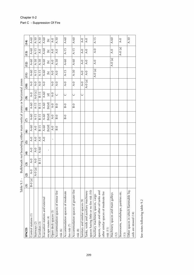
Chapter II-2
Part C - Suppression Of Fire
Table
9.1
-B
ulkh
eads
not
bou
ndin
g ei
ther
mai
n ve
rtic
al z
ones
or
hori
zont
al z
ones
See
note
s fo
llow
ing
tabl
e 9.
2
SPA
CES
(1)
(2)
(3)
(4)
(5)
(6)
(7)
(8)
(9)
(10)
(11)
(12)
(13)
(14)
Con
trol
sta
tions
(1)
B-0
[a]
A-0
A-0
A-0
A-0
A-6
0A
-60
A-6
0A
-0A
-0A
-60
A-6
0A
-60
A-6
0St
airw
ays
(2)
A-0
[a]
A-0
A-0
A-0
A-0
A-1
5A
-15
A-0
[c]
A-0
A-1
5A
-30
A-1
5A
-30
Cor
rido
rs (3
)B
-15
A-6
0A
-0B
-15
B-1
5B
-15
B-1
5A
-0A
-15
A-3
0A
-0A
-30
Evac
uatio
n st
atio
ns a
nd e
xter
nal
esca
pe r
oute
s (4
)-
A-0
A-6
0 [b
][d]
A-6
0 [b
][d]
A-6
0 [b
][d]
A-6
0 [d
]A
-0A
-60
[b]
A-6
0 [b
]A
-60
[b]
A-6
0 [b
]O
pen
deck
spa
ces
(5)
-A
-0A
-0A
-0A
-0A
-0A
-0A
-0A
-0A
-0A
ccom
mod
atio
n sp
aces
of m
inor
fire
ri
sk (6
)B
-0B
-0B
-0C
A-0
A-0
A-3
0A
-0A
-30
Acc
omm
odat
ion
spac
es o
f mod
erat
e fir
e ri
sk (7
)B
-0B
-0C
A-0
A-1
5A
-60
A-1
5A
-60
Acc
omm
odat
ion
spac
es o
f gre
ater
fire
ri
sk (8
)B
-0C
A-0
A-3
0A
-60
A-1
5A
-60
Sani
tary
and
sim
ilar
spac
es (9
)C
A-0
A-0
A-0
A-0
A-0
Tank
s, v
oids
and
aux
iliar
y m
achi
nery
sp
aces
hav
ing
little
or
no fi
re r
isk
(10)
A-0
[a]
A-0
A-0
A-0
A-0
Aux
iliar
y m
achi
nery
spa
ces,
car
go
spac
es, c
argo
and
oth
er o
il ta
nks
and
othe
r si
mila
r sp
aces
of m
oder
ate
fire
risk
(11)
A-0
[a]
A-0
A-0
A-1
5
Mac
hine
ry s
pace
s an
d m
ain
galle
ys
(12)
A-0
[a]
A-0
A-6
0
Stor
eroo
ms,
wor
ksho
ps, p
antr
ies
etc.
(1
3)A
-0 [
a]A
-0
Oth
er s
pace
s in
whi
ch fl
amm
able
liq-
uids
are
sto
wed
(14)
A-3
0
209
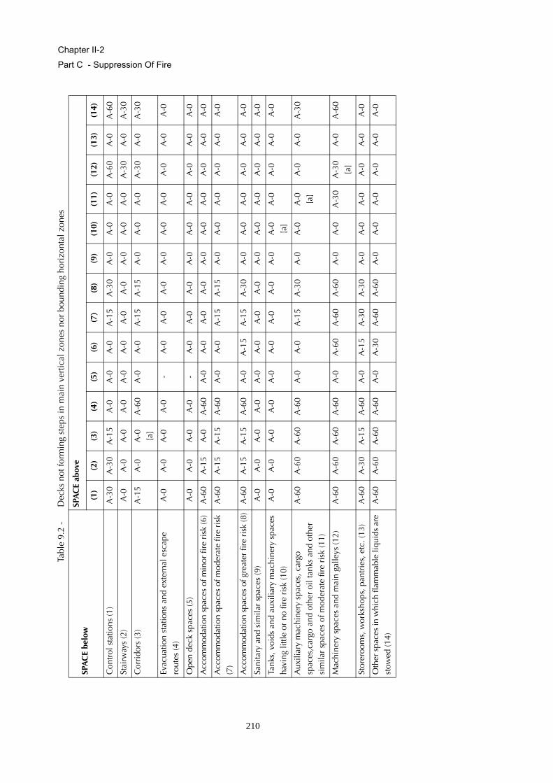
Chapter II-2
Part C - Suppression Of Fire
Table
9.2
-D
ecks
not
form
ing
step
s in
mai
n ve
rtic
al z
ones
nor
bou
ndin
g ho
rizo
ntal
zon
es
SPA
CE
belo
w
SPA
CE
abov
e
(1)
(2)
(3)
(4)
(5)
(6)
(7)
(8)
(9)
(10)
(11)
(12)
(13)
(14)
Con
trol
sta
tions
(1)
A-3
0A
-30
A-1
5A
-0A
-0A
-0A
-15
A-3
0A
-0A
-0A
-0A
-60
A-0
A-6
0
Stai
rway
s (2
)A
-0A
-0A
-0A
-0A
-0A
-0A
-0A
-0A
-0A
-0A
-0A
-30
A-0
A-3
0
Cor
rido
rs (3
)A
-15
A-0
A-0
[a
]A
-60
A-0
A-0
A-1
5A
-15
A-0
A-0
A-0
A-3
0A
-0A
-30
Evac
uatio
n st
atio
ns a
nd e
xter
nal e
scap
e ro
utes
(4)
A-0
A-0
A-0
A-0
-A
-0A
-0A
-0A
-0A
-0A
-0A
-0A
-0A
-0
Ope
n de
ck s
pace
s (5
)A
-0A
-0A
-0A
-0-
A-0
A-0
A-0
A-0
A-0
A-0
A-0
A-0
A-0
Acc
omm
odat
ion
spac
es o
f min
or fi
re r
isk
(6)
A-6
0A
-15
A-0
A-6
0A
-0A
-0A
-0A
-0A
-0A
-0A
-0A
-0A
-0A
-0
Acc
omm
odat
ion
spac
es o
f mod
erat
e fir
e ri
sk
(7)
A-6
0A
-15
A-1
5A
-60
A-0
A-0
A-1
5A
-15
A-0
A-0
A-0
A-0
A-0
A-0
Acc
omm
odat
ion
spac
es o
f gre
ater
fire
risk
(8)
A-6
0A
-15
A-1
5A
-60
A-0
A-1
5A
-15
A-3
0A
-0A
-0A
-0A
-0A
-0A
-0
Sani
tary
and
sim
ilar
spac
es (9
)A
-0A
-0A
-0A
-0A
-0A
-0A
-0A
-0A
-0A
-0A
-0A
-0A
-0A
-0
Tank
s, v
oids
and
aux
iliar
y m
achi
nery
spa
ces
havi
ng li
ttle
or n
o fir
e ri
sk (1
0)A
-0A
-0A
-0A
-0A
-0A
-0A
-0A
-0A
-0A
-0
[a]
A-0
A-0
A-0
A-0
Aux
iliar
y m
achi
nery
spa
ces,
car
go
spac
es,c
argo
and
oth
er o
il ta
nks
and
othe
r si
mila
r sp
aces
of m
oder
ate
fire
risk
(11)
A-6
0A
-60
A-6
0A
-60
A-0
A-0
A-1
5A
-30
A-0
A-0
A-0
[a
]A
-0A
-0A
-30
Mac
hine
ry s
pace
s an
d m
ain
galle
ys (1
2)A
-60
A-6
0A
-60
A-6
0A
-0A
-60
A-6
0A
-60
A-0
A-0
A-3
0A
-30
[a]
A-0
A-6
0
Stor
eroo
ms,
wor
ksho
ps, p
antr
ies,
etc
. (13
)A
-60
A-3
0A
-15
A-6
0A
-0A
-15
A-3
0A
-30
A-0
A-0
A-0
A-0
A-0
A-0
Oth
er s
pace
s in
whi
ch fl
amm
able
liqu
ids
are
stow
ed (1
4)A
-60
A-6
0A
-60
A-6
0A
-0A
-30
A-6
0A
-60
A-0
A-0
A-0
A-0
A-0
A-0
210
Chapter II-2
Part C - Suppression Of Fire
Note: To be applied to tables 9.1 and 9.2
[a] Where adjacent spaces are in the same numerical category and letter "a" appears, a bulkhead or deck betweensuch spaces need not be fitted if deemed unnecessary by the Society. For example, in category (12) a bulkheadneed not be required between a galley and its annexed pantries provided the pantry bulkheads and decks maintainthe integrity of the galley boundaries. A bulkhead is, however, required between a galley and a machinery spaceeven though both spaces are in category (12).
[b] [The ship's side, to the waterline in the lightest seagoing condition, superstructure and deckhouse sides situatedbelow and adjacent to the liferaft and evacuation slide embarkation areas may be reduced to A-30.
[c] Where public toilets are installed completely within the stairway enclosure, the public toilet bulkhead withinthe stairway enclosure can be of B class integrity.
[d] Where spaces of category (6), (7), (8) and (9) are located completely within the outer perimeter of the assemblystation, the bulkheads of these spaces are allowed to be of B-0 class integrity. Control positions for audio, video andlight installations may be considered as part of the assembly station.
2.2.3.3 Continuous "B" class ceilings or linings, in association with the relevant decks or bulkheads,may be accepted as contributing wholly or in part, to the required insulation and integrity of a division.
2.2.3.4 Construction and arrangement of saunas
2.2.3.4.1 The perimeter of the sauna shall be of "A" class boundaries and may include changing rooms,showers and toilets. The sauna shall be insulated to A-60 standard against other spaces except thoseinside of the perimeter and spaces of categories (5), (9) and (10).
2.2.3.4.2 Bathrooms with direct access to saunas may be considered as part of them. In such cases, thedoor between sauna and the bathroom need not comply with fire safety requirements.
2.2.3.4.3 The traditional wooden lining on the bulkheads and ceiling are permitted in the sauna. Theceiling above the oven shall be lined with a non-combustible plate with an air gap of at least 30 mm.The distance from the hot surfaces to combustible materials shall be at least 500 mm or the combustiblematerials shall be protected (e.g. non-combustible plate with an air gap of at least 30 mm).
2.2.3.4.4 The traditional wooden benches are permitted to be used in the sauna.
2.2.3.4.5 The sauna door shall open outwards by pushing.
2.2.3.4.6 Electrically heated ovens shall be provided with a timer.
2.2.4 Fire integrity of bulkheads and decks in ships carrying not more than 36 passengers
2.2.4.1 In addition to complying with the specific provisions for fire integrity of bulkheads and decks ofpassenger ships, the minimum fire integrity of bulkheads and decks shall be as prescribed in tables 9.3and 9.4.
2.2.4.2 The following requirements govern application of the tables:
.1 Tables 9.3 and 9.4 shall apply respectively to the bulkheads and decks separating adja-cent spaces;
211

Chapter II-2
Part C - Suppression Of Fire
.2 For determining the appropriate fire integrity standards to be applied to divisions betweenadjacent spaces, such spaces are classified according to their fire risk as shown in catego-ries (1) to (11) below. Where the contents and use of a space are such that there is a doubtas to its classification for the purpose of this regulation, or where it is possible to assigntwo or more classifications to a space, it shall be treated as a space within the relevantcategory having the most stringent boundary requirements. Smaller, enclosed roomswithin a space that have less than 30 % communicating openings to that space are con-sidered separate spaces. The fire integrity of the boundary bulkheads and decks of suchsmaller rooms shall be as prescribed in tables 9.3 and 9.4. The title of each category isintended to be typical rather than restrictive. The number in parentheses preceding eachcategory refers to the applicable column or row in the tables.
(1) Control stations
Spaces containing emergency sources of power and lighting.Wheelhouse and chartroom.Spaces containing the ship’s radio equipment.Fire control stations.Control room for propulsion machinery when located outside the machinery space.Spaces containing centralized fire alarm equipment.
(2) Corridors
Passenger and crew corridors and lobbies.
(3) Accommodation spaces
Spaces as defined in regulation 3.1 excluding corridors.
(4) Stairways
Interior stairways, lifts, totally enclosed emergency escape trunks, and escalators(other than those wholly contained within the machinery spaces) and enclosuresthereto.In this connection, a stairway which is enclosed only at one level shall be regarded aspart of the space from which it is not separated by a fire door.
(5) Service spaces (low risk)
Lockers and store-rooms not having provisions for the storage of flammable liquidsand having areas less than 4 m2 and drying rooms and laundries.
(6) Machinery spaces of category A
Spaces as defined in regulation 3.31.
212
Chapter II-2
Part C - Suppression Of Fire
(7) Other machinery spaces
Electrical equipment rooms (auto-telephone exchange, air-conditioning duct spaces).Spaces as defined in regulation 3.30 excluding machinery spaces of category A.
(8) Cargo spaces
All spaces used for cargo (including cargo oil tanks) and trunkways and hatchways tosuch spaces, other than special category spaces.
(9) Service spaces (high risk)
Galleys, pantries containing cooking appliances, paint and lamp rooms, lockers andstore-rooms having areas of 4 m2 or more, spaces for the storage of flammable liq-uids, saunas and workshops other than those forming part of the machinery spaces.
(10) Open decksOpen deck spaces and enclosed promenades having little or no fire risk. Enclosedpromenades should have no significant fire risk, meaning that furnishing should berestricted to deck furniture. In addition, such spaces should be naturally ventilated bypermanent openings. Air spaces (the space outside superstructures and deckhouses).
(11) Special category and ro-ro spaces
Spaces as defined in regulations 3.41 and 3.46;
.3 In determining the applicable fire integrity standard of a boundary between two spaceswithin a main vertical zone or horizontal zone which is not protected by an automaticsprinkler system complying with the provisions of the Fire Safety Systems Code orbetween such zones neither of which is so protected, the higher of the two values givenin the tables shall apply; and
.4 In determining the applicable fire integrity standard of a boundary between two spaceswithin a main vertical zone or horizontal zone which is protected by an automatic sprin-kler system complying with the provisions of the Fire Safety Systems Code or betweensuch zones both of which are so protected, the lesser of the two values given in the tablesshall apply. Where a zone with sprinklers and a zone without sprinklers meet withinaccommodation and service spaces, the higher of the two values given in the tables shallapply to the division between the zones.
2.2.4.3 Continuous "B" class ceilings or linings, in association with the relevant decks or bulkheads,may be accepted as contributing, wholly or in part, to the required insulation and integrity of a division.
213

Chapter II-2
Part C - Suppression Of Fire
Table 9.3 - Fire integrity of bulkheads separating adjacent spaces
Table 9.4 - Fire integrity of decks separating adjacent spaces
SPACES (1) (2) (3) (4) (5) (6) (7) (8) (9) (10) (11)Control stations (1) A-0
[c]A-0 A-60 A-0 A-15 A-60 A-15 A-60 A-60 * A-60
Corridors (2) C [e] B-0 [e]
A-0 [a] B-0 [e]
B-0 [e]
A-60 A-0 A-0 A-15 A-0 [d]
* A-15
Accommodation spaces (3) C [e] A-0 [a] B-0 [e]
B-0 [e]
A-60 A-0 A-0 A-15 A-0 [d]
* A-30 A-0 [d]
Stairways (4) A-0 [a] B-0 [e]
A-0 [a] B-0 [e]
A-60 A-0 A-0 A-15 A-0 [d]
* A-15
Service spaces (low risk) (5) C [e] A-60 A-0 A-0 A-0 * A-0Machinery spaces of category A (6)
* A-0 A-0 A-60 * A-60
Other machinery spaces (7) A-0 [b]
A-0 A-0 * A-0
Cargo spaces (8) * A-0 * A-0Service spaces (high risk) (9) A-0
[b]* A-30
Open decks (10) - A-0Special category spaces (11) A-0
SPACE below SPACE above(1) (2) (3) (4) (5) (6) (7) (8) (9) (10) (11)
Control stations (1) A-0 A-0 A-0 A-0 A-0 A-60 A-0 A-0 A-0 * A-30Corridors (2) A-0 * * A-0 * A-60 A-0 A-0 A-0 * A-0Accommodation spaces (3)
A-60 A-0 * A-0 * A-60 A-0 A-0 A-0 * A-30 A-0 [d]
Stairways (4) A-0 A-0 A-0 * A-0 A-60 A-0 A-0 A-0 * A-0Service spaces (low risk) (5)
A-15 A-0 A-0 A-0 * A-60 A-0 A-0 A-0 * A-0
Machinery spaces of cate-gory A (6)
A-60 A-60 A-60 A-60 A-60 * A-60 [f]
A-30 A-60 * A-60
Other machinery spaces (7)
A-15 A-0 A-0 A-0 A-0 A-0 * A-0 A-0 * A-0
Cargo spaces (8) A-60 A-0 A-0 A-0 A-0 A-0 A-0 * A-0 * A-0Service spaces (high risk) (9)
A-60 A-30 A-0 [d]
A-30 A-0 [d]
A-30 A-0 [d]
A-0 A-60 A-0 A-0 A-0 * A-30
Open decks (10) * * * * * * * * * - A-0Special category spaces (11)
A-60 A-15 A-30 A-0 [d]
A-15 A-0 A-30 A-0 A-0 A-30 A-0 A-0
214
Chapter II-2
Part C - Suppression Of Fire
Notes: To be applied to both tables 9.3 and 9.4 as appropriate.
[a] For clarification as to which applies, see paragraphs 2.2.2 and 2.2.5.
[b] Where spaces are of the same numerical category and superscript b appears, a bulkhead or deck of the ratingshown in the tables is only required when the adjacent spaces are for a different purpose, (e.g. in category (9)). Agalley next to a galley does not require a bulkhead but a galley next to a paint room requires an "A-0" bulkhead.
[c] Bulkhead separating the wheelhouse and chartroom from each other may have a "B-0" rating.
[d] See paragraphs 2.2.4.2.3 and 2.2.4.2.4.
[e] For the application of paragraph 2.2.1.1.2, "B-0" and "C", where appearing in table 9.3, shall be read as "A-0".
[f] Fire insulation need not be fitted if the machinery space in category (7), in the opinion of the Administration, haslittle or no fire risk.* Where an asterisk appears in the tables, the division is required to be of steel or other equivalentmaterial, but is not required to be of "A" class standard. However, where a deck, except in a category(10) space, is penetrated for the passage of electric cables, pipes and vent ducts, such penetrationsshould be made tight to prevent the passage of flame and smoke. Divisions between control stations(emergency generators) and open decks may have air intake openings without means for closure, unlessa fixed gas fire-fighting system is fitted. For the application of paragraph 2.2.1.1.2, an asterisk, where appearing in table 9.4, except for catego-ries (8) and (10), shall be read as “A-0”.
2.2.4.4 External boundaries which are required in regulation 11.2 to be of steel or other equivalentmaterial may be pierced for the fitting of windows and sidescuttles provided that there is no require-ment for such boundaries of passenger ships to have "A" class integrity. Similarly, in such boundarieswhich are not required to have "A" class integrity, doors may be constructed of materials which are tothe satisfaction of the Administration.
2.2.4.5 Saunas shall comply with paragraph 2.2.3.4.
2.2.5 Protection of stairways and lifts in accommodation area
2.2.5.1 Stairways shall be within enclosures formed of "A" class divisions, with positive means of clo-sure at all openings, except that:
.1 a stairway connecting only two decks need not be enclosed, provided the integrity of thedeck is maintained by proper bulkheads or self-closing doors in one 'tween-deck space.When a stairway is closed in one 'tween-deck space, the stairway enclosure shall be pro-tected in accordance with the tables for decks in paragraphs 2.2.3 or 2.2.4; and
.2 stairways may be fitted in the open in a public space, provided they lie wholly within thepublic space.
2.2.5.2 Lift trunks shall be so fitted as to prevent the passage of smoke and flame from one ‘tween-deckto another and shall be provided with means of closing so as to permit the control of draught andsmoke. Machinery for lifts located within stairway enclosures shall be arranged in a separate room, sur-rounded by steel boundaries, except that small passages for lift cables are permitted. Lifts which openinto spaces other than corridors, public spaces, special category spaces, stairways and external areasshall not open into stairways included in the means of escape.
215
Chapter II-2
Part C - Suppression Of Fire
2.3 Cargo ships except tankers
2.3.1 Methods of protection in accommodation area
2.3.1.1 One of the following methods of protection shall be adopted in accommodation and servicespaces and control stations:
.1 Method IC
The construction of internal divisional bulkheads of non-combustible "B" or "C" class divi-sions generally without the installation of an automatic sprinkler, fire detection and firealarm system in the accommodation and service spaces, except as required by regulation7.5.5.1; or
.2 Method IIC
The fitting of an automatic sprinkler, fire detection and fire alarm system as required byregulation 7.5.5.2 for the detection and extinction of fire in all spaces in which fire mightbe expected to originate, generally with no restriction on the type of internal divisionalbulkheads; or
.3 Method IIIC
The fitting of a fixed fire detection and fire alarm system as required by regulation 7.5.5.3,in spaces in which a fire might be expected to originate, generally with no restriction onthe type of internal divisional bulkheads, except that in no case must the area of anyaccommodation space or spaces bounded by an "A" or "B" class division exceed 50 m2.Consideration may be given by the Administration to increasing this area for publicspaces.
2.3.1.2 The requirements for the use of non-combustible materials in the construction and insulation ofboundary bulkheads of machinery spaces, control stations, service spaces, etc., and the protection ofthe above stairway enclosures and corridors will be common to all three methods outlined in paragraph2.3.1.1.
2.3.2 Bulkheads within accommodation area
2.3.2.1 Bulkheads required to be "B" class divisions shall extend from deck to deck and to the shell orother boundaries. However, where a continuous "B" class ceiling or lining is fitted on both sides of thebulkhead, the bulkhead may terminate at the continuous ceiling or lining.
2.3.2.2 Method IC
Bulkheads not required by this or other regulations for cargo ships to be "A" or "B" class divisions, shallbe of at least "C" class construction.
216

Chapter II-2
Part C - Suppression Of Fire
2.3.2.3 Method IIC
There shall be no restriction on the construction of bulkheads not required by this or other regulationsfor cargo ships to be "A" or "B" class divisions except in individual cases where "C" class bulkheads arerequired in accordance with table 9.5.
2.3.2.4 Method IIIC
There shall be no restriction on the construction of bulkheads not required for cargo ships to be "A" or"B" class divisions except that the area of any accommodation space or spaces bounded by a continu-ous "A" or "B" class division must in no case exceed 50 m2, except in individual cases where "C" classbulkheads are required in accordance with table 9.5. Consideration may be given by the Administrationto increasing this area for public spaces.
2.3.3 Fire integrity of bulkheads and decks
2.3.3.1 In addition to complying with the specific provisions for fire integrity of bulkheads and decks ofcargo ships, the minimum fire integrity of bulkheads and decks shall be as prescribed in tables 9.5 and9.6.
2.3.3.2 The following requirements shall govern application of the tables:
.1 Tables 9.5 and 9.6 shall apply respectively to the bulkheads and decks separating adja-cent spaces;
.2 For determining the appropriate fire integrity standards to be applied to divisions betweenadjacent spaces, such spaces are classified according to their fire risk as shown in catego-ries (1) to (11) below. Where the contents and use of a space are such that there is a doubtas to its classification for the purpose of this regulation, or where it is possible to assigntwo or more classifications to a space, it shall be treated as a space within the relevantcategory having the most stringent boundary requirements. Smaller, enclosed roomswithin a space that have less than 30% communicating openings to that space are con-sidered separate spaces. The fire integrity of the boundary bulkheads and decks of suchsmaller rooms shall be as prescribed in tables 9.5 and 9.6. The title of each category isintended to be typical rather than restrictive. The number in parentheses preceding eachcategory refers to the applicable column or row in the tables;
(1) Control stations
Spaces containing emergency sources of power and lighting.Wheelhouse and chartroom.Spaces containing the ship’s radio equipment.Fire control stations.Control room for propulsion machinery when located outside the machinery space.Spaces containing centralized fire alarm equipment.
217
Chapter II-2
Part C - Suppression Of Fire
(2) Corridors
corridors and lobbies.
(3) Accommodation spaces
Spaces as defined in regulation 3.1, excluding corridors.
(4) Stairways
Interior stairway, lifts, totally enclosed emergency escape trunks, and escalators(other than those wholly contained within the machinery spaces) and enclosuresthereto. In this connection, a stairway which is enclosed only at one level shall beregarded as part of the space from which it is not separated by a fire door.
(5) Service spaces (low risk)
Lockers and store-rooms not having provisions for the storage of flammable liquidsand having areas less than 4 m2 and drying rooms and laundries.
(6) Machinery spaces of category A
Spaces as defined in regulation 3.31.
(7) Other machinery spaces
Electrical equipment rooms (auto-telephone exchange, air-conditioning duct spaces).Spaces as defined in regulation 3.30 excluding machinery spaces of category A.
(8) Cargo spaces
All spaces used for cargo (including cargo oil tanks) and trunkways and hatchways tosuch spaces.
(9) Service spaces (high risk)
Galleys, pantries containing cooking appliances, saunas, paint lockers and store-rooms having areas of 4 m2 or more, spaces for the storage of flammable liquids, andworkshops other than those forming part of the machinery spaces.
(10) Open decks
Open deck spaces and enclosed promenades having little or no fire risk. To be con-sidered in this category, enclosed promenades shall have no significant fire risk,meaning that furnishings shall be restricted to deck furniture. In addition, such spacesshall be naturally ventilated by permanent openings.Air spaces (the space outside superstructures and deckhouses).
218
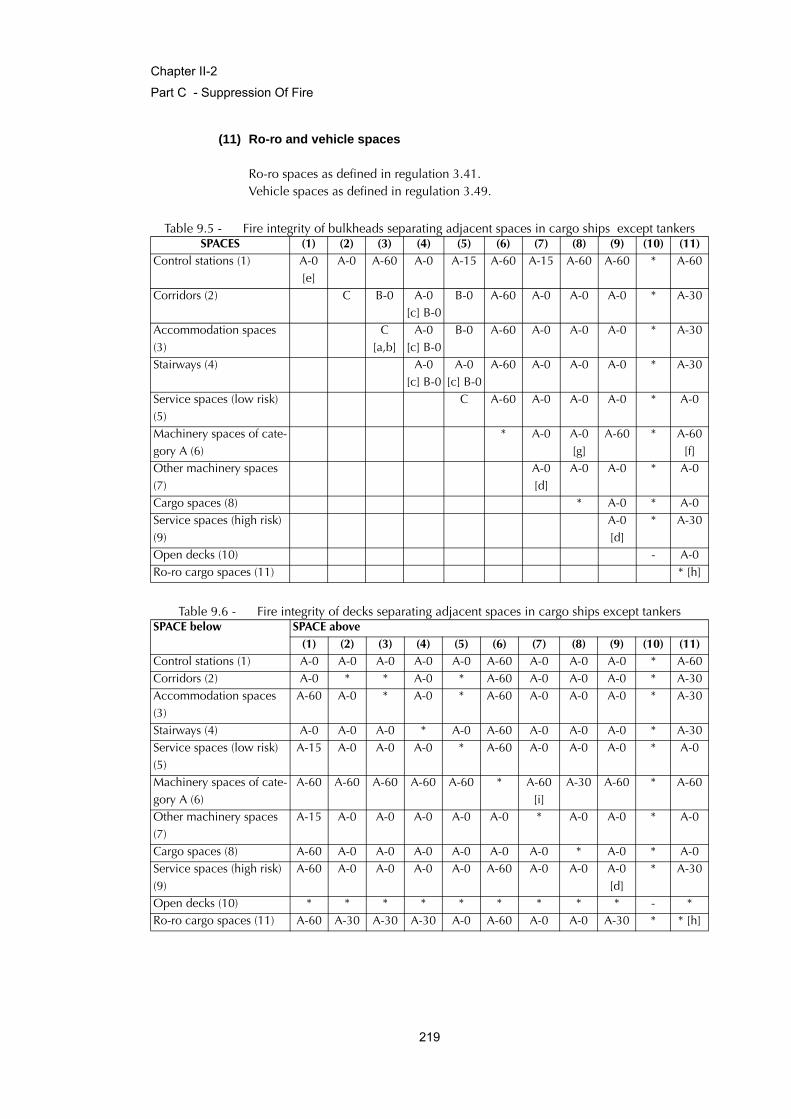
Chapter II-2
Part C - Suppression Of Fire
(11) Ro-ro and vehicle spaces
Ro-ro spaces as defined in regulation 3.41.Vehicle spaces as defined in regulation 3.49.
Table 9.5 - Fire integrity of bulkheads separating adjacent spaces in cargo ships except tankers
Table 9.6 - Fire integrity of decks separating adjacent spaces in cargo ships except tankers
SPACES (1) (2) (3) (4) (5) (6) (7) (8) (9) (10) (11)Control stations (1) A-0
[e]A-0 A-60 A-0 A-15 A-60 A-15 A-60 A-60 * A-60
Corridors (2) C B-0 A-0 [c] B-0
B-0 A-60 A-0 A-0 A-0 * A-30
Accommodation spaces (3)
C [a,b]
A-0 [c] B-0
B-0 A-60 A-0 A-0 A-0 * A-30
Stairways (4) A-0 [c] B-0
A-0 [c] B-0
A-60 A-0 A-0 A-0 * A-30
Service spaces (low risk) (5)
C A-60 A-0 A-0 A-0 * A-0
Machinery spaces of cate-gory A (6)
* A-0 A-0 [g]
A-60 * A-60 [f]
Other machinery spaces (7)
A-0 [d]
A-0 A-0 * A-0
Cargo spaces (8) * A-0 * A-0Service spaces (high risk) (9)
A-0 [d]
* A-30
Open decks (10) - A-0Ro-ro cargo spaces (11) * [h]
SPACE below SPACE above(1) (2) (3) (4) (5) (6) (7) (8) (9) (10) (11)
Control stations (1) A-0 A-0 A-0 A-0 A-0 A-60 A-0 A-0 A-0 * A-60Corridors (2) A-0 * * A-0 * A-60 A-0 A-0 A-0 * A-30Accommodation spaces (3)
A-60 A-0 * A-0 * A-60 A-0 A-0 A-0 * A-30
Stairways (4) A-0 A-0 A-0 * A-0 A-60 A-0 A-0 A-0 * A-30Service spaces (low risk) (5)
A-15 A-0 A-0 A-0 * A-60 A-0 A-0 A-0 * A-0
Machinery spaces of cate-gory A (6)
A-60 A-60 A-60 A-60 A-60 * A-60 [i]
A-30 A-60 * A-60
Other machinery spaces (7)
A-15 A-0 A-0 A-0 A-0 A-0 * A-0 A-0 * A-0
Cargo spaces (8) A-60 A-0 A-0 A-0 A-0 A-0 A-0 * A-0 * A-0Service spaces (high risk) (9)
A-60 A-0 A-0 A-0 A-0 A-60 A-0 A-0 A-0 [d]
* A-30
Open decks (10) * * * * * * * * * - *Ro-ro cargo spaces (11) A-60 A-30 A-30 A-30 A-0 A-60 A-0 A-0 A-30 * * [h]
219
Chapter II-2
Part C - Suppression Of Fire
Note: To be applied to tables 9.5 and 9.6 as appropriate.
[a] No special requirements are imposed upon bulkheads in methods IIC and IIIC fire protection.
[b] In case of method IIIC "B" class bulkheads of "B-0" rating shall be provided between spaces or groups of spacesof 50 m2 and over in area.
[c] For clarification as to which applies, see paragraphs 2.3.2 and 2.3.4.
[d] Where spaces are of the same numerical category and superscript d appear, a bulkhead or deck of the ratingshown in the tables is only required when the adjacent spaces are for a different purpose (e.g. in category (9)). Agalley next to a galley does not require a bulkhead but a galley next to a paint room requires an "A-0" bulkhead.
[e] Bulkheads separating the wheelhouse, chartroom and radio room from each other may have a "B-0" rating.
[f] An "A-0" rating may be used if no dangerous goods are intended to be carried or if such goods are stowed notless than 3 m horizontally from such a bulkhead.
[g] For cargo spaces in which dangerous goods are intended to be carried, regulation 19.3.8 applies.
[h] Bulkheads and decks separating ro-ro spaces shall be capable of being closed reasonably gastight and such divi-sions shall have "A" class integrity in so far as reasonable and practicable, if in the opinion of the Administration ithas little or no fire risk.
[i] Fire insulation need not be fitted if the machinery in category (7) if, in the opinion of the Administration, it has lit-tle or no fire risk.* Where an asterisk appears in the tables, the division is required to be of steel or other equivalentmaterial but is not required to be of "A" class standard. However, where a deck, except an open deck, ispenetrated for the passage of electric cables, pipes and vent ducts, such penetrations should be madetight to prevent the passage of flame and smoke. Divisions between control stations (emergency gener-ators) and open decks may have air intake openings without means for closure, unless a fixed gas fire-fighting system is fitted.
2.3.3.3 Continuous "B" class ceilings or linings, in association with the relevant decks or bulkheads,may be accepted as contributing, wholly or in part, to the required insulation and integrity of a division.
2.3.3.4 External boundaries which are required in regulation 11.2 to be of steel or other equivalentmaterial may be pierced for the fitting of windows and sidescuttles provided that there is no require-ment for such boundaries of cargo ships to have "A" class integrity. Similarly, in such boundaries whichare not required to have "A" class integrity, doors may be constructed of materials which are to the sat-isfaction of the Administration.
2.3.3.5 Saunas shall comply with paragraph 2.2.3.4.
2.3.4 Protection of stairways and lift trunks in accommodation spaces, service spaces and control stations
2.3.4.1 Stairways which penetrate only a single deck shall be protected, at a minimum, atone level by at least "B-0" class divisions and self-closing doors. Lifts which penetrateonly a single deck shall be surrounded by "A-0" class divisions with steel doors at bothlevels. Stairways and lift trunks which penetrate more than a single deck shall besurrounded by at least "A-0" class divisions and be protected by self-closing doors at alllevels.
220

Chapter II-2
Part C - Suppression Of Fire
2.3.4.2 On ships having accommodation for 12 persons or less, where stairways penetrate more than asingle deck and where there are at least two escape routes direct to the open deck at every accommo-dation level, the "A-0" requirements of paragraph 2.3.4.1 may be reduced to "B-0".
2.4 Tankers
2.4.1 Application
For tankers, only method IC as defined in paragraph 2.3.1.1 shall be used.
2.4.2 Fire integrity of bulkheads and decks
2.4.2.1 In lieu of paragraph 2.3 and in addition to complying with the specific provisionsfor fire integrity of bulkheads and decks of tankers, the minimum fire integrity ofbulkheads and decks shall be as prescribed in tables 9.7 and 9.8.
2.4.2.2 The following requirements shall govern application of the tables:
.1 Tables 9.7 and 9.8 shall apply respectively to the bulkhead and decks separating adjacentspaces;
.2 For determining the appropriate fire integrity standards to be applied to divisions betweenadjacent spaces, such spaces are classified according to their fire risk as shown in catego-ries (1) to (10) below. Where the contents and use of a space are such that there is a doubtas to its classification for the purpose of this regulation, or where it is possible to assigntwo or more classifications to a space, it shall be treated as a space within the relevantcategory having the most stringent boundary requirements. Smaller, enclosed areaswithin a space that have less than 30% communicating openings to that space are con-sidered separate areas. The fire integrity of the boundary bulkheads and decks of suchsmaller spaces shall be as prescribed in tables 9.7 and 9.8. The title of each category isintended to be typical rather than restrictive. The number in parentheses preceding eachcategory refers to the applicable column or row in the tables;
(1) Control stations
Spaces containing emergency sources of power and lighting.Wheelhouse and chartroom.Spaces containing the ship’s radio equipment.Fire control stations.Control room for propulsion machinery when located outside the machinery space.Spaces containing centralized fire alarm equipment.
(2) Corridors
Corridors and lobbies.
221
Chapter II-2
Part C - Suppression Of Fire
(3) Accommodation spaces
Spaces as defined in regulation 3.1, excluding corridors.
(4) Stairways
Interior stairways, lifts, totally enclosed emergency escape trunks, and escalators(other than those wholly contained within the machinery spaces) and enclosuresthereto. In this connection, a stairway which is enclosed only at one level shall beregarded as part of the space from which it is not separated by a fire door.
(5) Service spaces (low risk)
Lockers and store-rooms not having provisions for the storage of flammable liquidsand having areas less than 4 m2 and drying rooms and laundries.
(6) Machinery spaces of category A
Spaces as defined in regulation 3.31.
(7) Other machinery spaces
Electrical equipment rooms (auto-telephone exchange and airconditioning ductspaces).Spaces as defined in regulation 3.30 excluding machinery spaces of category A.
(8) Cargo pump-rooms
Spaces containing cargo pumps and entrances and trunks to such spaces.
(9) Service spaces (high risk)
Galleys, pantries containing cooking appliances, saunas, paint lockers and store-rooms having areas of 4 m2 or more, spaces for the storage of flammable liquids andworkshops other than those forming part of the machinery spaces.
(10) Open decks
Open deck spaces and enclosed promenades having little or no fire risk. To be con-sidered in this category, enclosed promenades shall have no significant fire risk,meaning that furnishings shall be restricted to deck furniture. In addition, such spacesshall be naturally ventilated by permanent openings.Air spaces (the space outside superstructures and deckhouses).
2.4.2.3 Continuous "B" class ceilings or linings, in association with the relevant decks or bulkheads,may be accepted as contributing, wholly or in part, to the required insulation and integrity of a division.
222
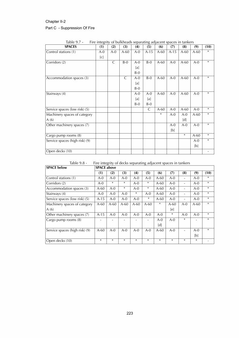
Chapter II-2
Part C - Suppression Of Fire
Table 9.7 - Fire integrity of bulkheads separating adjacent spaces in tankers
Table 9.8 - Fire integrity of decks separating adjacent spaces in tankers
SPACES (1) (2) (3) (4) (5) (6) (7) (8) (9) (10)Control stations (1) A-0
[c]A-0 A-60 A-0 A-15 A-60 A-15 A-60 A-60 *
Corridors (2) C B-0 A-0 [a] B-0
B-0 A-60 A-0 A-60 A-0 *
Accommodation spaces (3) C A-0 [a] B-0
B-0 A-60 A-0 A-60 A-0 *
Stairways (4) A-0 [a] B-0
A-0 [a] B-0
A-60 A-0 A-60 A-0 *
Service spaces (low risk) (5) C A-60 A-0 A-60 A-0 *Machinery spaces of category A (6)
* A-0 A-0 [d]
A-60 *
Other machinery spaces (7) A-0 [b]
A-0 A-0 *
Cargo pump rooms (8) * A-60 *Service spaces (high risk) (9) A-0
[b]*
Open decks (10) -
SPACE below SPACE above(1) (2) (3) (4) (5) (6) (7) (8) (9) (10)
Control stations (1) A-0 A-0 A-0 A-0 A-0 A-60 A-0 - A-0 *Corridors (2) A-0 * * A-0 * A-60 A-0 - A-0 *Accommodation spaces (3) A-60 A-0 * A-0 * A-60 A-0 - A-0 *Stairways (4) A-0 A-0 A-0 * A-0 A-60 A-0 - A-0 *Service spaces (low risk) (5) A-15 A-0 A-0 A-0 * A-60 A-0 - A-0 *Machinery spaces of category A (6)
A-60 A-60 A-60 A-60 A-60 * A-60 [e]
A-0 A-60 *
Other machinery spaces (7) A-15 A-0 A-0 A-0 A-0 A-0 * A-0 A-0 *Cargo pump rooms (8) - - - - - A-0
[d]A-0 * - *
Service spaces (high risk) (9) A-60 A-0 A-0 A-0 A-0 A-60 A-0 - A-0 [b]
*
Open decks (10) * * * * * * * * * -
223
Chapter II-2
Part C - Suppression Of Fire
Notes: To be applied to tables 9.7 and 9.8 as appropriate.
[a] For clarification as to which applies, see paragraphs 2.3.2 and 2.3.4.
[b] Where spaces are of the same numerical category and superscript b appears, a bulkhead or deck of the ratingshown in the tables is only required when the adjacent spaces are for a different purpose (e.g. in category (9)). Agalley next to a galley does not require a bulkhead but a galley next to a paint room requires an "A-0" bulkhead.
[c] Bulkheads separating the wheelhouse, chartroom and radio room from each other may have a "B-0" rating.
[d] Bulkheads and decks between cargo pump-rooms and machinery spaces of category A may be penetrated bycargo pump shaft glands and similar gland penetrations, provided that gas tight seals with efficient lubrication orother means of ensuring the permanence of the gas seal are fitted in way of the bulkheads or deck.
[e] Fire insulation need not be fitted if the machinery space in category (7) if, in the opinion of the Administration, ithas little or no fire risk.* Where an asterisk appears in the table, the division is required to be of steel or other equivalent mate-rial, but is not required to be of "A" class standard. However, where a deck, except an open deck, ispenetrated for the passage of electric cables, pipes and vent ducts, such penetrations should be madetight to prevent the passage of flame and smoke. Divisions between control stations (emergency gener-ators) and open decks may have air intake openings without means for closure, unless a fixed gas fire-fighting system is fitted.
2.4.2.4 External boundaries which are required in regulation 11.2 to be of steel or other equivalentmaterial may be pierced for the fitting of windows and sidescuttles provided that there is no require-ment for such boundarie s of tankers to have "A" class integrity. Similarly, in such boundaries which arenot required to have "A" class integrity, doors may be constructed of materials which are to the satisfac-tion of the Administration.
2.4.2.5 Exterior boundaries of superstructures and deckhouses enclosing accommodation and includ-ing any overhanging decks which support such accommodation, shall be constructed of steel andinsulated to "A-60" standard for the whole of the portions which face the cargo area and on the outwardsides for a distance of 3 m from the end boundary facing the cargo area. The distance of 3 m shall bemeasured horizontally and parallel to the middle line of the ship from the boundary which faces thecargo area at each deck level. In the case of the sides of those superstructures and deckhouses, suchinsulation shall be carried up to the underside of the deck of the navigation bridge.
2.4.2.6 Skylights to cargo pump-rooms shall be of steel, shall not contain any glass and shall be capa-ble of being closed from outside the pump-room.
2.4.2.7 Construction and arrangement of saunas shall comply with paragraph 2.2.3.4.
3 Penetration in fire -resisting divisions and prevention of heat transmission
3.1 Where "A" class divisions are penetrated, such penetrations shall be tested in accordance withthe Fire Test Procedures Code, subject to the provisions of paragraph 4.1.1.5. In the case of ventilationducts, paragraphs 7.1.2 and 7.3.1 apply. However, where a pipe penetration is made of steel or equiva-lent material having a thickness of 3mm or greater and a length of not less than 900 mm (preferably 450
224
Chapter II-2
Part C - Suppression Of Fire
mm on each side of the division), and no openings, testing is not required. Such penetrations shall besuitably insulated by extension of the insulation at the same level of the division.
3.2 Where "B" class divisions are penetrated for the passage of electric cables, pipes, trunks, ducts,etc., or for the fitting of ventilation terminals, lighting fixtures and similar devices, arrangements shall bemade to ensure that the fire resistance is not impaired, subject to the provisions of paragraph 7.3.2.Pipes other than steel or copper that penetrate "B" class divisions shall be protected by either:
.1 a fire tested penetration device, suitable for the fire resistance of the division pierced andthe type of pipe used; or
.2 a steel sleeve, having a thickness of not less than 1.8 mm and a length of not less than900 mm for pipe diameters of 150 mm or more and not less than 600 mm for pipe diam-eters of less than 150 mm (preferably equally divided to each side of the division). Thepipe shall be connected to the ends of the sleeve by flanges or couplings; or the clearancebetween the sleeve and the pipe shall not exceed 2.5 mm; or any clearance between pipeand sleeve shall be made tight by means of non-combustible or other suitable material.
3.3 Uninsulated metallic pipes penetrating "A" or "B" class divisions shall be of materials having amelting temperature which exceeds 950ºC for “A-0” and 850ºC for “B-0” class divisions.
3.4 In approving structural fire protection details, the Administration shall have regard to the risk ofheat transmission at intersections and terminal points of required thermal barriers. The insulation of adeck or bulkhead shall be carried past the penetration, intersection or terminal point for a distance of atleast 450 mm in the case of steel and aluminium structures. If a space is divided with a deck or a bulk-head of "A" class standard having insulation of different values, the insulation with the higher valueshall continue on the deck or bulkhead with the insulation of the lesser value for a distance of at least450 mm.
4 Protection of openings in fire resisting divisions
4.1 Openings in bulkheads and decks in passenger ships
4.1.1 Openings in "A" class divisions
4.1.1.1 Except for hatches between cargo, special category, store, and baggage spaces, and betweensuch spaces and the weather decks, openings shall be provided with permanently attached means ofclosing which shall be at least as effective for resisting fires as the divisions in which they are fitted.
4.1.1.2 The construction of doors and door frames in "A" class divisions, with the means of securingthem when closed, shall provide resistance to fire as well as to the passage of smoke and flame equiva-lent to that of the bulkheads in which the doors are situated, this being determined in accordance withthe Fire Test Procedures Code. Such doors and door frames shall be constructed of steel or other equiv-alent material. Watertight doors need not be insulated.
225
Chapter II-2
Part C - Suppression Of Fire
4.1.1.3 It shall be possible for each door to be opened and closed from each side of the bulkhead byone person only.
4.1.1.4 Fire doors in main vertical zone bulkheads, galley boundaries and stairway enclosures otherthan power-operated watertight doors and those which are normally locked, shall satisfy the followingrequirements:
.1 the doors shall be self-closing and be capable of closing with an angle of inclination ofup to 3.5º opposing closure;
.2 the approximate time of closure for hinged fire doors shall be no more than 40 s and noless than 10 s from the beginning of their movement with the ship in upright position. Theapproximate uniform rate of closure for sliding doors shall be of no more than 0.2 m/sand no less than 0.1 m/s with the ship in upright position;
.3 the doors, except those for emergency escape trunks, shall be capable of remote releasefrom the continuously manned central control station, either simultaneously or in groupsand shall be capable of release also individually from a position at both sides of the door.Release switches shall have an on-off function to prevent automatic resetting of thesystem;
.4 hold-back hooks not subject to central control station release are prohibited;
.5 a door closed remotely from the central control station shall be capable of being re-opened from both sides of the door by local control. After such local opening, the doorshall automatically close again;
.6 indication must be provided at the fire door indicator panel in the continuously mannedcentral control station whether each door is closed;
.7 the release mechanism shall be so designed that the door will automatically close in theevent of disruption of the control system or central power supply;
.8 local power accumulators for power-operated doors shall be provided in the immediatevicinity of the doors to enable the doors to be operated after disruption of the control sys-tem or central power supply at least ten times (fully opened and closed) using the localcontrols;
.9 disruption of the control system or central power supply at one door shall not impair thesafe functioning of the other doors;
.10 remote-released sliding or power-operated doors shall be equipped with an alarm thatsounds at least 5 s but no more than 10 s after the door being released from the centralcontrol station and before the door begins to move and continues sounding until the dooris completely closed;
226
Chapter II-2
Part C - Suppression Of Fire
.11 a door designed to re-open upon contacting an object in its path shall re-open not morethan 1 m from the point of contact;
.12 double-leaf doors equipped with a latch necessary for their fire integrity shall have a latchthat is automatically activated by the operation of the doors when released by the system;
.13 doors giving direct access to special category spaces which are power-operated and auto-matically closed need not be equipped with the alarms and remote-release mechanismsrequired in paragraphs 4.1.1.4.3 and 4.1.1.4.10;
.14 the components of the local control system shall be accessible for maintenance andadjusting;
.15 power-operated doors shall be provided with a control system of an approved type whichshall be able to operate in case of fire and be in accordance with the Fire Test ProceduresCode. This system shall satisfy the following requirements:
.15.1 the control system shall be able to operate the door at the temperature of at least200°C for at least 60 min, served by the power supply;
.15.2 the power supply for all other doors not subject to fire shall not be impaired; and
.15.3 at temperatures exceeding 200°C the control system shall be automatically isolatedfrom the power supply and shall be capable of keeping the door closed up to at least945°C.
4.1.1.5 In ships carrying not more than 36 passengers, where a space is protected by an automaticsprinkler fire detection and alarm system complying with the provisions the Fire Safety Systems Code orfitted with a continuous "B" class ceiling, openings in decks not forming steps in main vertical zones norbounding horizontal zones shall be closed reasonably tight and such decks shall meet the "A" classintegrity requirements in so far as is reasonable and practicable in the opinion of the Administration.
4.1.1.6 The requirements for "A" class integrity of the outer boundaries of a ship shall not apply to glasspartitions, windows and sidescuttles, provided that there is no requirement for such boundaries to have"A" class integrity in paragraph 4.1.3.3. The requirements for "A" class integrity of the outer boundariesof the ship shall not apply to exterior doors, except for those in superstructures and deckhouses facinglifesaving appliances, embarkation and external assembly station areas, external stairs and open decksused for escape routes. Stairway enclosure doors need not meet this requirement.
4.1.1.7 Except for watertight doors, weathertight doors (semi-watertight doors), doors leading to theopen deck and doors which need to be reasonably gastight, all "A" class doors located in stairways,public spaces and main vertical zone bulkheads in escape routes shall be equipped with a self-closinghose port of material, construction and fire resistance which is equivalent to the door into which it is fit-ted, and shall be a 150 mm square clear opening with the door closed and shall be inset into the loweredge of the door, opposite the door hinges or, in the case of sliding doors, nearest the opening.
227
Chapter II-2
Part C - Suppression Of Fire
4.1.1.8 Where it is necessary that a ventilation duct passes through a main vertical zone division, afail-safe automatic closing fire damper shall be fitted adjacent to the division. The damper shall also becapable of being manually closed from each side of the division. The operating position shall be readilyaccessible and be marked in red light-reflecting colour. The duct between the division and the dampershall be of steel or other equivalent material and, if necessary, insulated to comply with the require-ments of paragraph 3.1. The damper shall be fitted on at least one side of the division with a visibleindicator showing whether the damper is in the open position.
4.1.2 Openings in "B" class divisions
4.1.2.1 Doors and door frames in "B" class divisions and means of securing them shall provide amethod of closure which shall have resistance to fire equivalent to that of the divisions, this being deter-mined in accordance with the Fire Test Procedure Code except that ventilation openings may bepermitted in the lower portion of such doors. Where such opening is in or under a door the total netarea of any such opening or openings shall not exceed 0.05 m2. Alternatively, a non-combustible airbalance duct routed between the cabin and the corridor, and located below the sanitary unit is permit-ted where the cross-sectional area of the duct does not exceed 0.05 m2. All ventilation openings shallbe fitted with a grill made of non-combustible material. Doors shall be non-combustible.
4.1.2.2 Cabin doors in "B" class divisions shall be of a self-closing type. Hold-back hooks are notpermitted.
4.1.2.3 The requirements for "B" class integrity of the outer boundaries of a ship shall not apply to glasspartitions, windows and sidescuttles. Similarly, the requirements for "B" class integrity shall not apply toexterior doors in superstructures and deckhouses. For ships carrying not more than 36 passengers, theAdministration may permit the use of combustible materials in doors separating cabins from the indi-vidual interior sanitary spaces such as showers.
4.1.2.4 In ships carrying not more than 36 passengers, where an automatic sprinkler system complyingwith the provisions of the Fire Safety Systems Code is fitted:
.1 openings in decks not forming steps in main vertical zones nor bounding horizontalzones shall be closed reasonably tight and such decks shall meet the "B" class integrityrequirements in so far as is reasonable and practicable in the opinion of the Administra-tion; and
.2 openings in corridor bulkheads of "B" class materials shall be protected in accordancewith the provisions of paragraph 2.2.2.
4.1.3 Windows and sidescuttles
4.1.3.1 Windows and sidescuttles in bulkheads within accommodation and service spaces and controlstations other than those to which the provisions of paragraph 4.1.1.6 and of paragraph 4.1.2.3 apply,shall be so constructed as to preserve the integrity requirements of the type of bulkheads in which theyare fitted, this being determined in accordance with the Fire Test Procedures Code.
228
Chapter II-2
Part C - Suppression Of Fire
4.1.3.2 Notwithstanding the requirements of tables 9.1 to 9.4, windows and sidescuttles in bulkheadsseparating accommodation and service spaces and control stations from weather shall be constructedwith frames of steel or other suitable material. The glass shall be retained by a metal glazing bead orangle.
4.1.3.3 Windows facing life-saving appliances, embarkation and assembly stations, external stairs andopen decks used for escape routes, and windows situated below liferaft and escape slide embarkationareas shall have fire integrity as required in table 9.1. Where automatic dedicated sprinkler heads areprovided for windows, "A-0" windows may be accepted as equivalent. To be considered under this par-agraph, the sprinkler heads must either be:
.1 dedicated heads located above the windows, and installed in addition to the conven-tional ceiling sprinklers; or
.2 conventional ceiling sprinkler heads arranged such that the window is protected by anaverage application rate of at least 5 l/m2 and the additional window area is included inthe calculation of the area of coverage. Windows located in the ship’s side below the life-boat embarkation area shall have fire integrity at least equal to "A-0" class.
4.2 Doors in fire-resisting divisions in cargo ships
4.2.1 The fire resistance of doors shall be equivalent to that of the division in which they are fitted,this being determined in accordance with the Fire Test Procedures Code. Doors and door frames in "A"class divisions shall be constructed of steel. Doors in "B" class divisions shall be non-combustible.Doors fitted in boundary bulkheads of machinery spaces of category A shall be reasonably gastight andself-closing. In ships constructed according to method IC, the Administration may permit the use ofcombustible materials in doors separating cabins from individual interior sanitary accommodation suchas showers.
4.2.2 Doors required to be self-closing shall not be fitted with hold-back hooks. However, hold-backarrangements fitted with remote release devices of the fail-safe type may be utilized.
4.2.3 In corridor bulkheads ventilation openings may be permitted in and under the doors of cabinsand public spaces. Ventilation openings are also permitted in "B" class doors leading to lavatories,offices, pantries, lockers and store rooms. Except as permitted below, the openings shall be providedonly in the lower half of a door. Where such an opening is in or under a door the total net area of anysuch opening or openings shall not exceed 0.05 m2. Alternatively, a non-combustible air balance ductrouted between the cabin and the corridor, and located below the sanitary unit is permitted where thecross-sectional area of the duct does not exceed 0.05 m2. Ventilation openings, except those under thedoor, shall be fitted with a grille made of non-combustible material.
4.2.4 Watertight doors need not be insulated.
229
Chapter II-2
Part C - Suppression Of Fire
5 Protection of openings in machinery spaces boundaries
5.1 Application
5.1.1 The provision of this paragraph shall apply to machinery spaces of category A and, where theAdministration considers it desirable, to other machinery spaces.
5.2 Protection of openings in machinery space boundaries
5.2.1 The number of skylights, doors, ventilators, openings in funnels to permit exhaust ventilationand other openings to machinery spaces shall be reduced to a minimum consistent with the needs ofventilation and the proper and safe working of the ship.
5.2.2 Skylights shall be of steel and shall not contain glass panels.
5.2.3 Means of control shall be provided for closing power-operated doors or actuating releasemechanisms on doors other than power-operated watertight doors. The control shall be located outsidethe space concerned, where they will not be cut off in the event of fire in the space it serves.
5.2.4 In passenger ships, the means of control required in paragraph 5.2.3 shall be situated at onecontrol position or grouped in as few positions as possible to the satisfaction of the Administration.Such positions shall have safe access from the open deck.
5.2.5 In passenger ships, doors, other than power-operated watertight doors shall be so arranged thatpositive closure is assured in case of fire in the space by power-operated closing arrangements or by theprovision of self-closing doors capable of closing against an inclination of 3.5° opposing closure, andhaving a fail-safe hold-back arrangement, provided with a remotely operated release device. Doors foremergency escape trunks need not be fitted with a fail-safe hold-back facility and a remotely operatedrelease device.
5.2.6 Windows shall not be fitted in machinery space boundaries. However, this does not precludethe use of glass in control rooms within the machinery spaces.
6 Protection of cargo space boundaries
6.1 In passenger ships carrying more than 36 passengers, the boundary bulkheads and decks ofspecial category and ro-ro spaces shall be insulated to "A-60" class standard. However, where a cate-gory (5), (9) and (10) space, as defined in paragraph 2.2.3, is on one side of the division the standardmay be reduced to "A-0". Where fuel oil tanks are below a special category space, the integrity of thedeck between such spaces may be reduced to "A-0" standard.
6.2 In passenger ships carrying not more than 36 passengers, the boundary bulkheads of specialcategory spaces shall be insulated as required for category (11) spaces in table 9.3 and the horizontalboundaries as required for category (11) spaces in table 9.4.
230
Chapter II-2
Part C - Suppression Of Fire
6.3 In passenger ships carrying not more than 36 passengers the boundary bulkheads and decks ofclosed and open ro-ro spaces shall have a fire integrity as required for category (8) spaces in table 9.3and the horizontal boundaries as required for category (8) spaces in table 9.4.
6.4 In passenger ships, indicators shall be provided on the navigating bridge which shall indicatewhen any fire door leading to or from the special category spaces is closed.
6.5 In tankers, for the protection of cargo tanks carrying crude oil and petroleum products having aflashpoint not exceeding 60°C, materials readily rendered ineffective by heat shall not be used forvalves, fittings, tank opening covers, cargo vent piping, and cargo piping so as to prevent the spread offire to the cargo.
7 Ventilation systems
7.1 Duct and dampers
7.1.1 Ventilation ducts shall be of non-combustible material. However, short ducts, not generally
exceeding 2 m in length and with a free cross-sectional area* not exceeding 0.02 m2, need not be non-combustible subject to the following conditions:
.1 the ducts are made of a material which has low flame spread characteristics;
.2 the ducts are only used at the end of the ventilation device; and
.3 the ducts are not situated less than 600 mm, measured along the duct, from an opening inan "A" or "B" class division including continuous "B" class ceiling.
7.1.2 The following arrangements shall be tested in accordance with the Fire Test Procedures Code:
.1 fire dampers, including their relevant means of operation; and
.2 duct penetrations through "A" class divisions. However, the test is not required wheresteel sleeves are directly joined to ventilation ducts by means of riveted or screwedflanges or by welding.
7.2 Arrangement of ducts
7.2.1 The ventilation systems for machinery spaces of category A, vehicle spaces, ro-ro spaces, gal-leys, special category spaces and cargo spaces shall, in general, be separated from each other and fromthe ventilation systems serving other spaces. Except that the galley ventilation systems on cargo ships ofless than 4,000 gross tonnage and in passenger ships carrying not more than 36 passengers, need not
* The term "free cross-sectional area" means, even in the case of a pre-insulated duct, the area calculated on the basis of theinner diameter of the duct.
231
Chapter II-2
Part C - Suppression Of Fire
be completely separated, but may be served by separate ducts from a ventilation unit serving otherspaces. In any case, an automatic fire damper shall be fitted in the galley ventilation duct near the ven-tilation unit. Ducts provided for the ventilation of machinery spaces of category A, galleys, vehiclespaces, ro-ro spaces or special category spaces shall not pass through accommodation spaces, servicespaces or control stations unless they comply with the conditions specified in paragraphs 7.2.1.1.1 to7.2.1.1.4 or 7.2.1.2.1 and 7.2.1.2.2 below:
.1.1 the ducts are constructed of steel having a thickness of at least 3 mm and 5 mm forducts the widths or diameters of which are up to and including 300 mm and 760 mmand over respectively and, in the case of such ducts, the widths or diameters of whichare between 300 mm and 760 mm having a thickness obtained by interpolation;
.1.2 the ducts are suitably supported and stiffened;
.1.3 the ducts are fitted with automatic fire dampers close to the boundaries penetrated;and
.1.4 the ducts are insulated to "A-60" class standard from the machinery spaces, galleys,vehicle spaces, ro-ro spaces or special category spaces to a point at least 5 m beyondeach fire damper;
or
.2.1 the ducts are constructed of steel in accordance with paragraphs 7.2.1.1.1 and7.2.1.1.2; and
.2.2 the ducts are insulated to "A-60" class standard throughout the accommodationspaces, service spaces or control stations; except that penetrations of main zone divi-sions shall also comply with the requirements of paragraph 4.1.1.8.
7.2.2 Ducts provided for ventilation to accommodation spaces, service spaces or control stationsshall not pass through machinery spaces of category A, galleys, vehicle spaces, ro-ro spaces or specialcategory spaces unless they comply with the conditions specified in paragraphs 7.2.2.1.1 to 7.2.2.1.3or 7.2.2.2.1 and 7.2.2.2.2 below:
.1.1 the ducts where they pass through a machinery space of category A, galley, vehiclespace, ro-ro space or special category space are constructed of steel in accordancewith paragraphs 7.2.1.1.1 and 7.2.1.1.2;
.1.2 automatic fire dampers are fitted close to the boundaries penetrated; and
.1.3 the integrity of the machinery space, galley, vehicle space, ro-ro space or special cat-egory space boundaries is maintained at the penetrations;
or
232

Chapter II-2
Part C - Suppression Of Fire
.2.1 the ducts where they pass through a machinery space of category A, galley, vehiclespace, ro-ro space or special category space are constructed of steel in accordancewith paragraphs 7.2.1.1.1 and 7.2.1.1.2; and
.2.2 the ducts are insulated to "A-60" standard within the machinery space, galley, vehiclespace, ro-ro space or special category space; except that penetrations of main zonedivisions shall also comply with the requirements of paragraph 4.1.1.8.
7.3 Details of duct penetrations
7.3.1 Where a thin plated duct with a free cross-sectional area equal to, or less than, 0.02 m2 passesthrough "A" class bulkheads or decks, the opening shall be lined with a steel sheet sleeve having athickness of at least 3 mm and a length of at least 200 mm, divided preferably into 100 mm on eachside of the bulkhead or, in the case of the deck, wholly laid on the lower side of the decks pierced.Where ventilation ducts with a free cross-sectional area exceeding 0.02 m2 pass through "A" class bulk-heads or decks, the opening shall be lined with a steel sheet sleeve. However, where such ducts are ofsteel construction and pass through a deck or bulkhead, the ducts and sleeves shall comply with thefollowing:
.1 The sleeves shall have a thickness of at least 3 mm and a length of at least 900 mm. Whenpassing through bulkheads, this length shall be divided preferably into 450 mm on eachside of the bulkhead. These ducts, or sleeves lining such ducts, shall be provided with fireinsulation. The insulation shall have at least the same fire integrity as the bulkhead ordeck through which the duct passes; and
.2 Ducts with a free cross-sectional area exceeding 0.075 m2 shall be fitted with fire damp-ers in addition to the requirements of paragraph 7.3.1.1. The fire damper shall operateautomatically, but shall also be capable of being closed manually from both sides of thebulkhead or deck. The damper shall be provided with an indicator which shows whetherthe damper is open or closed. Fire dampers are not required, however, where ducts passthrough spaces surrounded by "A" class divisions, without serving those spaces, providedthose ducts have the same fire integrity as the divisions which they pierce. Fire dampersshall be easily accessible. Where they are placed behind ceilings or linings, these ceilingsor linings shall be provided with an inspection door on which a plate reporting the iden-tification number of the fire damper is provided. The fire damper identification numbershall also be placed on any remote controls required.
7.3.2 Ventilation ducts with a free cross-sectional area exceeding 0.02 m2 passing through "B" classbulkheads shall be lined with steel sheet sleeves of 900 mm in length divided preferably into 450 mmon each side of the bulkheads unless the duct is of steel for this length.
7.4 Ventilation systems for passenger ships carrying more than 36 passengers
7.4.1 The ventilation system of a passenger ship carrying more than 36 passengers shall be in com-pliance with the following additional requirements.
233

Chapter II-2
Part C - Suppression Of Fire
7.4.2 In general, the ventilation fans shall be so disposed that the ducts reaching the various spacesremain within the main vertical zone.
7.4.3 Where ventilation systems penetrate decks, precautions shall be taken, in addition to thoserelating to the fire integrity of the deck required by paragraphs 3.1 and 4.1.1.5, to reduce the likelihoodof smoke and hot gases passing from one 'tween-deck space to another through the system. In additionto insulation requirements contained in paragraph 7.4, vertical ducts shall, if necessary, be insulated asrequired by the appropriate tables 9.1 and 9.2.
7.4.4 Except in cargo spaces, ventilation ducts shall be constructed of the following materials:
.1 ducts not less than 0.075 m2 in free cross-sectional area and all vertical ducts servingmore than a single 'tween-deck space shall be constructed of steel or other equivalentmaterial;
.2 ducts less than 0.075 m2 in free cross-sectional area other than the vertical ducts referredto in paragraph 7.4.4.1, shall be constructed of non-combustible materials. Where suchducts penetrate "A" or "B" class division due regard shall be given to ensuring the fireintegrity of the division; and
.3 short length of duct, not in general exceeding 0.02m2 in free cross-sectional area nor 2 min length, need not be non-combustible provided that all of the following conditions aremet:
.3.1 the duct is constructed of a material which has low flame spread characteristics;
.3.2 the duct is used only at the terminal end of the ventilation system; and
.3.3 the duct is not located closer than 600mm measured along its length to a penetrationof an "A" or "B" class division, including continuous "B" class ceilings.
7.4.5 Stairway enclosures shall be ventilated and served by an independent fan and duct systemwhich shall not serve any other spaces in the ventilation systems.
7.4.6 Exhaust ducts shall be provided with hatches for inspection and cleaning. The hatches shall belocated near the fire dampers.
7.5 Exhaust ducts from galley ranges
7.5.1 Requirements for passenger ships carrying more than 36 passengers
Exhaust ducts from galley ranges shall meet the requirements of paragraphs 7.2.1.2.1 and 7.2.1.2.2 andshall be fitted with:
.1 a grease trap readily removable for cleaning unless an alternative approved greaseremoval system is fitted;
234
Chapter II-2
Part C - Suppression Of Fire
.2 a fire damper located in the lower end of the duct which is automatically and remotelyoperated, and in addition a remotely operated fire damper located in the upper end of theduct;
.3 a fixed means for extinguishing a fire within the duct;
.4 remote-control arrangements for shutting off the exhaust fans and supply fans, for operat-ing the fire dampers mentioned in paragraph 7.5.1.2 and for operating the fire-extinguishing system, which shall be placed in a position close to the entrance to the gal-ley. Where a multi-branch system is installed, a remote means located with the abovecontrols shall be provided to close all branches exhausting through the same main ductbefore an extinguishing medium is released into the system; and
.5 suitably located hatches for inspection and cleaning.
7.5.2 Requirements for cargo ships and passenger ships carrying not more than 36 passenger ships
7.5.2.1 Where they pass through accommodation spaces or spaces containing combustible materials,the exhaust ducts from galley ranges shall be constructed of "A" class divisions. Each exhaust duct shallbe fitted with:
.1 a grease trap readily removable for cleaning;
.2 a fire damper located in the lower end of the duct;
.3 arrangements, operable from within the galley, for shutting off the exhaust fans; and
.4 fixed means for extinguishing a fire within the duct.
Regulation 10Fire fighting
1 Purpose
The purpose of this regulation is to suppress and swiftly extinguish a fire in the space of origin. For thispurpose, the following functional requirements shall be met:
.1 fixed fire extinguishing systems shall be installed having due regard to the fire growthpotential of the protected spaces; and
.2 fire extinguishing appliances shall be readily available.
235
Chapter II-2
Part C - Suppression Of Fire
2 Water supply systems
Ships shall be provided with fire pumps, fire mains, hydrants and hoses complying with the applicablerequirements of this regulation.
2.1 Fire mains and hydrants
2.1.1 General
Materials readily rendered ineffective by heat shall not be used for fire mains and hydrants unless ade-quately protected. The pipes and hydrants shall be so placed that the fire hoses may be easily coupledto them. The arrangement of pipes and hydrants shall be such as to avoid the possibility of freezing.Suitable drainage provisions shall be provided for fire main piping. Isolation valves shall be installed forall open deck fire main branches used for purposes other than fire fighting. In ships where deck cargomay be carried, the positions of the hydrants shall be such that they are always readily accessible andthe pipes shall be arranged as far as practicable to avoid risk of damage by such cargo.
2.1.2 Ready availability of water supply
The arrangements for the ready availability of water supply shall be:
.1 in passenger ships:
.1.1 of 1,000 gross tonnage and upwards such that at least one effective jet of water isimmediately available from any hydrant in an interior location and so as to ensure thecontinuation of the output of water by the automatic starting of one required firepump;
.1.2 of less than 1,000 gross tonnage by automatic start of at least one fire pump or byremote starting from the navigation bridge of at least one fire pump. If the pump startsautomatically or if the bottom valve cannot be opened from where the pump isremotely started, the bottom valve shall always be kept open; and
.1.3 if fitted with periodically unattended machinery spaces in accordance with regula-tion II-1/54, the Administration shall determine provisions for fixed water fire-extinguishing arrangement for such spaces equivalent to those required for normallyattended machinery spaces;
.2 in cargo ships:
.2.1 to the satisfaction of the Administration; and
.2.2 with a periodically unattended machinery space or when only one person is requiredon watch, there shall be immediate water delivery from the fire main system at a suit-able pressure, either by remote starting of one of the main fire pumps with remotestarting from the navigating bridge and fire control station, if any, or permanent pres-
236
Chapter II-2
Part C - Suppression Of Fire
surization of the fire main system by one of the main fire pumps, except that theAdministration may waive this requirement for cargo ships of less than 1,600 grosstonnage if the fire pump starting arrangement in the machinery space is in an easilyaccessible position.
2.1.3 Diameter of fire mains
The diameter of the fire main and water service pipes shall be sufficient for the effective distribution ofthe maximum required discharge from two fire pumps operating simultaneously, except that in the caseof cargo ships the diameter need only be sufficient for the discharge of 140 m3/h.
2.1.4 Isolating valves and relief valves
2.1.4.1 Isolating valves to separate the section of the fire main within the machinery space containingthe main fire pump or pumps from the rest of the fire main shall be fitted in an easily accessible andtenable position outside the machinery spaces. The fire main shall be so arranged that when the isolat-ing valves are shut all the hydrants on the ship, except those in the machinery space referred to above,can be supplied with water by another fire pump or an emergency fire pump. The emergency firepump, its seawater inlet, and suction and delivery pipes and isolating valves shall be located outside themachinery space. If this arrangement cannot be made, the sea-chest may be fitted in the machineryspace if the valve is remotely controlled from a position in the same compartment as the emergency firepump and the suction pipe is as short as practicable. Short lengths of suction or discharge piping maypenetrate the machinery space, provided they are enclosed in a substantial steel casing, or are insulatedto A-60 class standards. The pipes shall have substantial wall thickness, but in no case less than 11 mm,and shall be welded except for the flanged connection to the sea inlet valve.
2.1.4.2 A valve shall be fitted to serve each fire hydrant so that any fire hose may be removed while thefire pumps are in operation.
2.1.4.3 Relief valves shall be provided in conjunction with fire pumps if the pumps are capable ofdeveloping a pressure exceeding the design pressure of the water service pipes, hydrants and hoses.These valves shall be so placed and adjusted as to prevent excessive pressure in any part of the firemain system.
2.1.4.4 In tankers, isolation valves shall be fitted in the fire main at poop front in a protected positionand on the tank deck at intervals of not more than 40 m to preserve the integrity of the fire main systemin case of fire or explosion.
2.1.5 Number and position of hydrants
2.1.5.1 The number and position of hydrants shall be such that at least two jets of water not emanatingfrom the same hydrant, one of which shall be from a single length of hose, may reach any part of theship normally accessible to the passengers or crew while the ship is being navigated and any part of anycargo space when empty, any ro-ro space or any vehicle space in which latter case the two jets shallreach any part of the space, each from a single length of hose. Furthermore, such hydrants shall be posi-tioned near the accesses to the protected spaces.
237
Chapter II-2
Part C - Suppression Of Fire
2.1.5.2 In addition to the requirements in the paragraph 2.1.5.1, passenger ships shall comply with thefollowing:
.1 in the accommodation, service and machinery spaces the number and position ofhydrants shall be such that the requirements of paragraph 2.1.5.1 may be complied withwhen all watertight doors and all doors in main vertical zone bulkheads are closed; and
.2 where access is provided to a machinery space of category A at a low level from an adja-cent shaft tunnel, two hydrants shall be provided external to,but near the entrance to that machinery space. Where such access is provided from otherspaces, in one of those spaces two hydrants shall be provided near the entrance to themachinery space of category A. Such provision need not be made where the tunnel oradjacent spaces are not part of the escape route.
2.1.6 Pressure at hydrants
With the two pumps simultaneously delivering water through the nozzles specified in paragraph 2.3.3,with the quantity of water as specified in paragraph 2.1.3, through any adjacent hydrants, the followingminimum pressures shall be maintained at all hydrants:
.1 for passenger ships:
4,000 gross tonnage and upwards 0.40 N/mm2
less than 4,000 gross tonnage 0.30 N/mm2;
.2 for cargo ships,
6,000 gross tonnage and upwards 0.27N/mm2
less than 6,000 gross tonnage; 0.25 N/mm2; and
.3 the maximum pressure at any hydrant shall not exceed that at which the effective controlof a fire hose can be demonstrated.
2.1.7 International shore connection
2.1.7.1 Ships of 500 gross tonnage and upwards shall be provided with at least one international shoreconnection complying with the Fire Safety Systems Code.
2.1.7.2 Facilities shall be available enabling such a connection to be used on either side of the ship.
238
Chapter II-2
Part C - Suppression Of Fire
2.2 Fire pumps
2.2.1 Pumps accepted as fire pumps
Sanitary, ballast, bilge or general service pumps may be accepted as fire pumps, provided that they arenot normally used for pumping oil and that if they are subject to occasional duty for the transfer orpumping of oil fuel, suitable change-over arrangements are fitted.
2.2.2 Number of fire pumps
Ships shall be provided with independently driven fire pumps as follows:
.1 in passenger ships of:
4,000 gross tonnage and upwards at least three
less than 4,000 gross tonnage at least two
.2 in cargo ships of:
1,000 gross tonnage and upwards at least two
less than 1,000 gross tonnage at least two power driven pumps,one of which shall be independentlydriven.
2.2.3 Arrangement of fire pumps and fire mains
2.2.3.1 Fire pumps
The arrangement of sea connections, fire pumps and their sources of power shall be as to ensure that:
.1 in passenger ships of l,000 gross tonnage and upwards, in the event of a fire in any onecompartment all the fire pumps will not be put out of action; and
.2 in passenger ships of less than 1,000 gross tonnage and in cargo ships, if a fire in any onecompartment could put all the pumps out of action, there shall be an alternative meansconsisting of an emergency fire pump complying with the provisions of the Fire SafetySystems Code with its source of power and sea connection located outside the spacewhere the main fire pumps or their sources of power are located.
2.2.3.2 Requirements for the space containing the emergency fire pump
2.2.3.2.1 Location of the space
The space containing the fire pump shall not be contiguous to the boundaries of machinery spaces ofcategory A or those spaces containing main fire pumps. Where this is not practicable, the commonbulkhead between the two spaces shall be insulated to a standard of structural fire protection equiva-lent to that required for a control station in regulation 9.2.3.3.
239
Chapter II-2
Part C - Suppression Of Fire
2.2.3.2.2 Access to the emergency fire pump
No direct access shall be permitted between the machinery space and the space containing the emer-gency fire pump and its source of power. When this is impracticable, the Administration may accept anarrangement where the access is by means of an airlock with the door of the machinery space being ofA-60 class standard, and the other door being at least steel, both reasonably gastight, self-closing andwithout any hold back arrangements. Alternatively, the access may be through a watertight door capa-ble of being operated from a space remote from the machinery space and the space containing theemergency fire pump and unlikely to be cut off in the event of fire in those spaces. In such cases, a sec-ond means of access to the space containing the emergency fire pump and its source of power shall beprovided.
2.2.3.2.3 Ventilation of the emergency fire pump spaceVentilation arrangements to the space containing the independent source of power for the emergencyfire pump shall be such as to preclude, as far as practicable, the possibility of smoke from a machineryspace fire entering or being drawn into that space.
2.2.3.3 Additional pumps for cargo ships
In addition, in cargo ships where other pumps, such as general service, bilge and ballast, etc., are fittedin a machinery space, arrangements shall be made to ensure that at least one of these pumps, havingthe capacity and pressure required by paragraphs 2.1.6.2 and 2.2.4.2, is capable of providing water tothe fire main.
2.2.4 Capacity of fire pumps
2.2.4.1 Total capacity of required fire pumps
The required fire pumps shall be capable of delivering for fire-fighting purposes a quantity of water, atthe pressure specified in paragraph 2.1.6, as follows:
.1 pumps in passenger ships, the quantity of water is not less than two thirds of the quantityrequired to be dealt with by the bilge pumps when employed for bilge pumping; and
.2 pumps in cargo ships, other than any emergency pump, the quantity of water is not lessthan four thirds of the quantity required under regulation II-1/21 to be dealt with by eachof the independent bilge pumps in a passenger ship of the same dimension whenemployed in bilge pumping, provided that in no cargo ship need the total required capac-ity of the fire pumps exceed 180 m3/h.
2.2.4.2 Capacity of each fire pump
Each of the required fire pumps (other than any emergency pump required in paragraph 2.2.3.1.2 forcargo ships) shall have a capacity not less than 80% of the total required capacity divided by the mini-mum number of required fire pumps but in any case not less than 25 m3/h and each such pump shall inany event be capable of delivering at least the two required jets of water. These fire pumps shall becapable of supplying the fire main system under the required conditions. Where more pumps than the
240
Chapter II-2
Part C - Suppression Of Fire
minimum of required pumps are installed such additional pumps shall have a capacity of at least 25m3/h and shall be capable of delivering at least the two jets of water required in paragraph 2.1.5.1.
2.3 Fire hoses and nozzles
2.3.1 General specifications
2.3.1.1 Fire hoses shall be of non-perishable material approved by the Administration and shall be suf-ficient in length to project a jet of water to any of the spaces in which they may be required to be used.Each hose shall be provided with a nozzle and the necessary couplings. Hoses specified in this chapteras "fire hoses" shall, together with any necessary fittings and tools, be kept ready for use in conspicuouspositions near the water service hydrants or connections. Additionally, in interior locations in passengerships carrying more than 36 passengers fire hoses shall be connected to the hydrants at all times. Firehoses shall have a length of at least 10 m, but not more than:
.1 15 m in machinery spaces;
.2 20 m in other spaces and open decks; and
.3 25 m for open decks on ships with a maximum breadth in excess of 30 m.
2.3.1.2 Unless one hose and nozzle is provided for each hydrant in the ship, there shall be completeinterchangeability of hose couplings and nozzles.
2.3.2 Number and diameter of fire hoses
2.3.2.1 Ships shall be provided with fire hoses the number and diameter of which shall be to the satis-faction of the Administration.
2.3.2.2 In passenger ships, there shall be at least one fire hose for each of the hydrants required by par-agraph 2.1.5 and these hoses shall be used only for the purposes of extinguishing fires or testing thefire-extinguishing apparatus at fire drills and surveys.
2.3.2.3 In cargo ships:
.1 of 1,000 gross tonnage and upwards, the number of fire hoses to be provided shall be onefor each 30 m length of the ship and one spare but in no case less than five in all. Thisnumber does not include any hoses required in any engine or boiler room. The Adminis-tration may increase the number of hoses required so as to ensure that hoses in sufficientnumber are available and accessible at all times, having regard to the type of ship and thenature of trade in which the ship is employed. Ships carrying dangerous goods in accord-ance with regulation 19 shall be provided with 3 hoses and nozzles, in addition to thoserequired above; and
241
Chapter II-2
Part C - Suppression Of Fire
.2 of less than 1,000 gross tonnage, the number of fire hoses to be provided shall be calcu-lated in accordance with the provisions of paragraph 2.3.2.3.1. However, the number ofhoses shall in no case be less than three.
2.3.3 Size and types of nozzles
2.3.3.1 For the purposes of this chapter, standard nozzle sizes shall be 12 mm, 16 mm and 19 mm oras near thereto as possible. Larger diameter nozzles may be permitted at the discretion of theAdministration.
2.3.3.2 For accommodation and service spaces, a nozzle size greater than 12 mm need not be used.
2.3.3.3 For machinery spaces and exterior locations, the nozzle size shall be such as to obtain themaximum discharge possible from two jets at the pressure mentioned in paragraph 2.1.6 from thesmallest pump, provided that a nozzle size greater than 19 mm need not be used.
2.3.3.4 Nozzles shall be of an approved dual-purpose type (i.e., spray/jet type) incorporating a shutoff.
3 Portable fire extinguishers
3.1 Type and design
Portable fire extinguishers shall comply with the requirements of the Fire Safety Systems Code.
3.2 Arrangement of fire extinguishers
3.2.1 Accommodation spaces, service spaces and control stations shall be provided with portablefire extinguishers of appropriate types and in sufficient number to the satisfaction of the Administration.Ships of 1,000 gross tonnage and upwards shall carry at least five portable fire extinguishers.
3.2.2 One of the portable fire extinguishers intended for use in any space shall be stowed near theentrance to that space.
3.2.3 Carbon dioxide fire extinguishers shall not be placed in accommodation spaces. In control sta-tions and other spaces containing electrical or electronic equipment or appliances necessary for thesafety of the ship, fire extinguishers should be provided whose extinguishing media are neither electri-cally conductive nor harmful to the equipment and appliances.
3.2.4 Fire extinguishers shall be situated ready for use at easily visible places, which can be reachedquickly and easily at any time in the event of a fire, and in such a way that their serviceability is notimpaired by the weather, vibration or other external factors. Portable fire extinguishers shall be pro-vided with devices which indicate whether they have been used.
242
Chapter II-2
Part C - Suppression Of Fire
3.3 Spare charges
3.3.1 Spare charges shall be provided for 100% of the first 10 extinguishers and 50% of the remain-ing fire extinguishers capable of being recharged on board. Not more than 60 total spare charges arerequired. Instructions for recharging shall be carried on board.
3.3.2 For fire extinguishers which cannot be recharged onboard, additional portable fire extinguish-ers of the same quantity, type, capacity and number as determined in paragraph 3.3.1 above shall beprovided in lieu of spare charges.
4 Fixed fire-extinguishing systems
4.1 Types of fixed fire extinguishing systems
4.1.1 A fixed fire extinguishing system required by paragraph 5 below may be any of the followingsystems:
.1 a fixed gas fire-extinguishing system complying with the provisions of the Fire Safety Sys-tems Code;
.2 a fixed high-expansion foam fire-extinguishing system complying with the provisions ofthe Fire Safety Systems Code; and
.3 a fixed pressure water-spraying fire-extinguishing system complying with the provisions ofthe Fire Safety Systems Code.
4.1.2 Where a fixed fire-extinguishing system not required by this chapter is installed, it shall meetthe requirements of the relevant regulations of this chapter and the Fire Safety Systems Code.
4.1.3 Fire-extinguishing systems using Halon 1211, 1301, and 2402 and perfluorocarbons shall beprohibited.
4.1.4 In general, the Administration shall not permit the use of steam as a fire-extinguishing mediumin fixed fire-extinguishing systems. Where the use of steam is permitted by the Administration, it shallbe used only in restricted areas as an addition to the required fire-extinguishing system and shall com-ply with the requirements of the Fire Safety System Code.
4.2 Closing appliances for fixed gas fire-extinguishing systemsWhere a fixed gas fire-extinguishing system is used, openings which may admit air to, or allow gas toescape from, a protected space shall be capable of being closed from outside the protected space.
243
Chapter II-2
Part C - Suppression Of Fire
4.3 Storage rooms of fire-extinguishing medium
When the fire-extinguishing medium is stored outside a protected space, it shall be stored in a roomwhich is located behind the forward collision bulkhead, and is used for no other purposes. Anyentrance to such a storage room shall preferably be from the open deck and shall be independent of theprotected space. If the storage space is located below deck, it shall be located no more than one deckbelow the open deck and shall be directly accessible by a stairway or ladder from the open deck.Spaces which are located below deck or spaces where access from the open deck is not provided, shallbe fitted with a mechanical ventilation system designed to take exhaust air from the bottom of the spaceand shall be sized to provide at least 6 air changes per hour. Access doors shall open outwards, andbulkheads and decks including doors and other means of closing any opening therein, which form theboundaries between such rooms and adjacent enclosed spaces shall be gastight. For the purpose of theapplication of tables 9.1 to 9.8, such storage rooms shall be treated as fire control stations.
4.4 Water pumps for other fire-extinguishing systems
Pumps, other than those serving the fire main, required for the provision of water for fire-extinguishingsystems required by this chapter, their sources of power and their controls shall be installed outside thespace or spaces protected by such systems and shall be so arranged that a fire in the space or spacesprotected will not put any such system out of action.
5 Fire extinguishing arrangements in machinery spaces
5.1 Machinery spaces containing oil-fired boilers or oil fuel units
5.1.1 Fixed fire-extinguishing systems
Machinery spaces of category A containing oil-fired boilers or oil fuel units shall be provided with anyone of the fixed fire-extinguishing systems in paragraph 4.1. In each case, if the engine and boilerrooms are not entirely separate, or if fuel oil can drain from the boiler room into the engine-room, thecombined engine and boiler rooms shall be considered as one compartment.
5.1.2 Additional fire-extinguishing arrangements
5.1.2.1 There shall be in each boiler room or at an entrance outside of the boiler room at least oneportable foam applicator unit complying with the provisions of the Fire Safety Systems Code.
5.1.2.2 There shall be at least two portable foam extinguishers or equivalent in each firing space ineach boiler room and in each space in which a part of the oil fuel installation is situated. There shall benot less than one approved foam-type extinguisher of at least 135 l capacity or equivalent in each boilerroom. These extinguishers shall be provided with hoses on reels suitable for reaching any part of theboiler room. In the case of domestic boilers of less than 175 kW an approved foam-type extinguisher ofat least 135 l capacity is not required.
244
Chapter II-2
Part C - Suppression Of Fire
5.1.2.3 In each firing space there shall be a receptacle containing at least 0.1 m3 sand, sawdustimpregnated with soda, or other approved dry material, along with a suitable shovel for spreading thematerial. An approved portable extinguisher may be substituted as an alternative.
5.2 Machinery spaces containing internal combustion machinery
5.2.1 Fixed fire-extinguishing systems
Machinery spaces of category A containing internal combustion machinery shall be provided with oneof the fixed fire-extinguishing systems in paragraph 4.1.
5.2.2 Additional fire-extinguishing arrangements
5.2.2.1 There shall be at least one portable foam applicator unit complying with the provisions of theFire Safety Systems Code.
5.2.2.2 There shall be in each such space approved foam-type fire extinguishers, each of at least 45 lcapacity or equivalent, sufficient in number to enable foam or its equivalent to be directed on to anypart of the fuel and lubricating oil pressure systems, gearing and other fire hazards. In addition, thereshall be provided a sufficient number of portable foam extinguishers or equivalent which shall be solocated that no point in the space is more than 10 m walking distance from an extinguisher and thatthere are at least two such extinguishers in each such space. For smaller spaces of cargo ships theAdministration may consider relaxing this requirement.
5.3 Machinery spaces containing steam turbines or enclosed steam engines
5.3.1 Fixed fire-extinguishing systems
In spaces containing steam turbines or enclosed steam engines used for main propulsion or other pur-poses having in the aggregate a total output of not less than 375 kW, one of the fire-extinguishingsystems specified in paragraph 4.1 shall be provided if such spaces are periodically unattended.
5.3.2 Additional fire-extinguishing arrangements
5.3.2.1 There shall be approved foam fire extinguishers each of at least 45 l capacity or equivalent suf-ficient in number to enable foam or its equivalent to be directed on to any part of the pressurelubrication system, on to any part of the casings enclosing pressure lubricated parts of the turbines,engines or associated gearing, and any other fire hazards. However, such extinguishers shall not berequired if protection, at least equivalent to that required by this subparagraph, is provided in suchspaces by a fixed fire-extinguishing system fitted in compliance with paragraph 4.1.
5.3.2.2 There shall be a sufficient number of portable foam extinguishers or equivalent which shall beso located that no point in the space is more than 10 m walking distance from an extinguisher and thatthere are at least two such extinguishers in each such space, except that such extinguishers shall not berequired in addition to any provided in compliance with paragraph 5.1.2.2.
245
Chapter II-2
Part C - Suppression Of Fire
5.4 Other machinery spaces
Where, in the opinion of the Administration, a fire hazard exists in any machinery space for which nospecific provisions for fire-extinguishing appliances are prescribed in paragraphs 5.1, 5.2 and 5.3, thereshall be provided in, or adjacent to, that space such a number of approved portable fire extinguishers orother means of fire extinction as the Administration may deem sufficient.
5.5 Additional requirements for passenger ships
In passenger ships carrying more than 36 passengers, each machinery space of category A shall be pro-
vided with at least two suitable water fog applicators.*
5.6 Fixed local application fire-fighting systems
5.6.1 Paragraph 5.6 shall apply to passenger ships of 500 gross tonnage and above and cargo ships of2000 gross tonnage and above.
5.6.2 Machinery spaces of category A above 500 m3 in volume shall, in addition to the fixed fire-extinguishing system required in paragraph 5.1.1, be protected by an approved type of fixed water-based or equivalent local application fire-fighting system, based on the guidelines developed by the
Organization.** In the case of periodically unattended machinery spaces, the fire fighting system shallhave both automatic and manual release capabilities. In the case of continuously manned machineryspaces, the fire-fighting system is only required to have a manual release capability.
5.6.3 Fixed local application fire-fighting systems are to protect areas such as the following withoutthe necessity of engine shutdown, personnel evacuation, or sealing of the spaces:
.1 the fire hazard portions of internal combustion machinery used for the ship’s main pro-pulsion and power generation;
.2 boiler fronts;
.3 the fire hazard portions of incinerators; and
.4 purifiers for heated fuel oil.
5.6.4 Activation of any local application system shall give a visual and distinct audible alarm in theprotected space and at continuously manned stations. The alarm shall indicate the specific system acti-vated. The system alarm requirements described within this paragraph are in addition to, and not asubstitute for, the detection and fire alarm system required elsewhere in this chapter.
* A water fog applicator might consist of a metal L-shaped pipe, the long limb being about 2 m in length capable of being fittedto a fire hose and the short limb being about 250 mm in length fitted with a fixed water fog nozzle or capable of being fitted witha water spray nozzle.** Refer to the Guidelines for the approval of fixed water-based local application fire-fighting systems for use in category Amachinery spaces (MSC/Circ.913).
246
Chapter II-2
Part C - Suppression Of Fire
6 Fire -extinguishing arrangements in control stations, accommodation and service spaces
6.1 Sprinkler systems in passenger ships
6.1.1 Passenger ships carrying more than 36 passengers shall be equipped with an automatic sprin-kler, fire detection and fire alarm system of an approved type complying with the requirements of theFire Safety Systems Code in all control stations, accommodation and service spaces, including corridorsand stairways. Alternatively, control stations, where water may cause damage to essential equipment,may be fitted with an approved fixed fire-extinguishing system of another type. Spaces having little orno fire risk such as voids, public toilets, carbon dioxide rooms and similar spaces need not be fittedwith an automatic sprinkler system.
6.1.2 In passenger ships carrying not more than 36 passengers, when a fixed smoke detection andfire alarm system complying with the provisions of the Fire Safety Systems Code is provided only in cor-ridors, stairways and escape routes within accommodation spaces, an automatic sprinkler system shallbe installed in accordance with regulation 7.5.3.2.
6.2 Sprinkler systems for cargo ships
In cargo ships in which method IIC specified in regulation 9.2.3.1.1.2 is adopted, an automatic sprin-kler, fire detection and fire alarm system shall be fitted in accordance with the requirements inregulation 7.5.5.2.
6.3 Spaces containing flammable liquid
6.3.1 Paint lockers shall be protected by:
.1 a carbon dioxide system, designed to give a minimum volume of free gas equal to 40% ofthe gross volume of the protected space;
.2 a dry powder system, designed for at least 0.5 kg powder/m3;
.3 a water spraying or sprinkler system, designed for 5 l/m2 min. Water spraying systemsmay be connected to the fire main of the ship; or
.4 a system providing equivalent protection, as determined by the Administration. In anycase, the system shall be operable from outside the protected space.
6.3.2 Flammable liquid lockers shall be protected by an appropriate fire-extinguishing arrangementapproved by the Administration.
6.3.3 For lockers of a deck area of less than 4 m2, which do not give access to accommodationspaces, a carbon dioxide portable fire extinguisher sized to provide a minimum volume of free gasequal to 40% of the gross volume of the space may be accepted in lieu of a fixed system. A discharge
247
Chapter II-2
Part C - Suppression Of Fire
port shall be arranged in the locker to allow the discharge of the extinguisher without having to enterinto the protected space. The required portable fire extinguisher shall be stowed adjacent to the port.Alternatively, a port or hose connection may be provided to facilitate the use of fire main water.
6.4 Deep-fat cooking equipment
Deep-fat cooking equipment shall be fitted with the following:
.1 an automatic or manual extinguishing system tested to an international standard accepta-
ble to the Organization;*
.2 a primary and backup thermostat with an alarm to alert the operator in the event of failureof either thermostat;
.3 arrangements for automatically shutting off the electrical power upon activation of theextinguishing system;
.4 an alarm for indicating operation of the extinguishing system in the galley where theequipment is installed; and
.5 controls for manual operation of the extinguishing system which are clearly labelled forready use by the crew.
7 Fire -extinguishing arrangements in cargo spaces
7.1 Fixed gas fire-extinguishing systems for general cargo
7.1.1 Except as provided for in paragraph 7.2, the cargo spaces of passenger ships of 1,000 gross ton-nage and upwards shall be protected by a fixed carbon dioxide or inert gas fire-extinguishing systemcomplying with the provisions of the Fire Safety Systems Code or by a fixed high expansion foam fire-extinguishing system which gives equivalent protection.
7.1.2 Where it is shown to the satisfaction of the Administration that a passenger ship is engaged onvoyages of such short duration that it would be unreasonable to apply the requirements of paragraph7.1.1 and also in ships of less than 1,000 gross tonnage, the arrangements in cargo spaces shall be tothe satisfaction of the Administration, provided that the ship is fitted with steel hatch covers and effec-tive means of closing all ventilators and other openings leading to the cargo spaces.
7.1.3 Except for ro-ro and vehicle spaces, cargo spaces on cargo ships of 2,000 gross tonnage andupwards shall be protected by a fixed carbon dioxide or inert gas fire-extinguishing system complyingwith the provisions of the Fire Safety Systems Code, or by a fire-extinguishing system which gives equiv-alent protection.
* Refer to the recommendations by the International Organization for Standardization, in particular, Publication ISO 15371:2000on Fire-extinguishing systems for protection of galley deep-fat cooking equipment.
248
Chapter II-2
Part C - Suppression Of Fire
7.1.4 The Administration may exempt from the requirements of paragraphs 7.1.3 and 7.2, cargospaces of any cargo ship if constructed, and solely intended for, the carriage of ore, coal, grain, unsea-soned timber, non-combustible cargoes or cargoes which, in the opinion of the Administration,
constitute a low fire risk.* Such exemptions may be granted only if the ship is fitted with steel hatch cov-ers and effective means of closing ventilators and other openings leading to the cargo spaces. Whensuch exemptions are granted, the Administration shall issue an Exemption Certificate, irrespective of thedate of construction of the ship concerned, in accordance with regulation I/12(a)(vi), and shall ensurethat the list of cargoes the ship is permitted to carry is attached to the Exemption Certificate.
7.2 Fixed gas fire-extinguishing systems for dangerous goods
A ship engaged in the carriage of dangerous goods in any cargo spaces shall be provided with a fixedcarbon dioxide or inert gas fire-extinguishing system complying with the provisions of the Fire SafetySystems Code or with a fire-extinguishing system which, in the opinion of the Administration, givesequivalent protection for the cargoes carried.
8 Cargo tank protection
8.1 Fixed deck foam systems
8.1.1 For tankers of 20,000 tonnes deadweight and upwards, a fixed deck foam system shall be pro-vided in accordance with the requirements of the Fire Safety Systems Code, except that, in lieu of theabove, the Administration, after having given consideration to the ship’s arrangement and equipment,may accept other fixed installations if they afford protection equivalent to the above, in accordancewith regulation I/5. The requirements for alternative fixed installations shall comply with the require-ments in paragraph 8.1.2.
8.1.2 In accordance with paragraph 8.1.1, where the Administration accepts an equivalent fixedinstallation in lieu of the fixed deck foam system, the installation shall:
.1 be capable of extinguishing spill fires and also preclude ignition of spilled oil not yetignited; and
.2 be capable of combating fires in ruptured tanks.
8.1.3 Tankers of less than 20,000 tonnes deadweight shall be provided with a deck foam systemcomplying with the requirements of the Fire Safety Systems Code.
* Refer to the Code of Safe Practice for Solid Bulk Cargoes – Emergency Schedule B14, entry for coal and to the List of solidbulk cargoes which are non-combustible or constitute a low fire risk or for which a fixed gas fire-extinguishing system isineffective (MSC/Circ.671).
249
Chapter II-2
Part C - Suppression Of Fire
9 Protection of cargo pump rooms in tankers
9.1 Fixed fire-extinguishing systems
Each cargo pump-room shall be provided with one of the following fixed fire-extinguishing systemsoperated from a readily accessible position outside the pump-room. Cargo pump-rooms shall be pro-vided with a system suitable for machinery spaces of category A. 9.1.1 A carbon dioxide systemcomplying with the provisions the Fire Safety Systems Code and with the following:
.1 the alarms giving audible warning of the release of fire-extinguishing medium shall besafe for use in a flammable cargo vapour/air mixture; and
.2 a notice shall be exhibited at the controls stating that due to the electrostatic ignition haz-ard, the system is to be used only for fire extinguishing and not for inerting purposes.
9.1.2 A high-expansion foam system complying with the provisions of the Fire Safety Systems Code,provided that the foam concentrate supply is suitable for extinguishing fires involving the cargoescarried.
9.1.3 A fixed pressure water-spraying system complying with the provisions of the Fire Safety SystemsCode.
9.2 Quantity of fire-extinguishing mediumWhere the extinguishing medium used in the cargo pump-room system is also used in systems servingother spaces, the quantity of medium provided or its delivery rate need not be more than the maximumrequired for the largest compartment.
10 Fire -fighter’s outfits
10.1 Types of fire-fighter’s outfits
Fire-fighter’s outfits shall comply with the Fire Safety Systems Code.
10.2 Number of fire-fighter’s outfits
10.2.1 Ships shall carry at least two fire-fighter’s outfits.
10.2.2 In addition, in passenger ships there shall be provided:
.1 for every 80 m, or part thereof, of the aggregate of the lengths of all passenger spaces andservice spaces on the deck which carries such spaces or, if there is more than one suchdeck, on the deck which has the largest aggregate of such lengths, two fire-fighter’s outfitsand, in addition, two sets of personal equipment, each set comprising the items stipulatedin the Fire Safety Systems Code. In passenger ships carrying more than 36 passengers, two
250
Chapter II-2
Part C - Suppression Of Fire
additional fire-fighter’s outfits shall be provided for each main vertical zone. However, forstairway enclosures which constitute individual main vertical zones and for the main ver-tical zones in the fore or aft end of a ship which do not contain spaces of categories (6),(7), (8) or (12) defined in regulation 9.2.2.3, no additional fire-fighter’s outfits arerequired; and
.2 ships carrying more than 36 passengers, for each pair of breathing apparatus there shallbe provided one water fog applicator which shall be stored adjacent to such apparatus.
10.2.3 In addition, in tankers, two fire-fighter’s outfits shall be provided.
10.2.4 The Administration may require additional sets of personal equipment and breathing apparatus,having due regard to the size and type of the ship.
10.2.5 Two spare charges shall be provided for each required breathing apparatus. Passenger shipscarrying not more than 36 passengers and cargo ships that are equipped with suitably located meansfor fully recharging the air cylinders free from contamination, need carry only one spare charge for eachrequired apparatus. In passenger ships carrying more than 36 passengers, at least two spare charges foreach breathing apparatus shall be provided.
10.3 Storage of fire-fighter’s outfits
10.3.1 The fire-fighter’s outfits or sets of personal equipment shall be kept ready for use in an easilyaccessible location that is permanently and clearly marked and, where more than one fire-fighter’s out-fit or more than one set of personal equipment is carried, they shall be stored in widely separatedpositions.
10.3.2 In passenger ships, at least two fire-fighter’s outfits and, in addition, one set of personal equip-ment shall be available at any one position. At least two fire-fighter’s outfits shall be stored in each mainvertical zone.
Regulation 11Structural integrity
1 Purpose
The purpose of this regulation is to maintain structural integrity of the ship preventing partial or wholecollapse of the ship structures due to strength deterioration by heat. For this purpose, materials used inthe ships’ structure shall ensure that the structural integrity is not degraded due to fire.
251
Chapter II-2
Part C - Suppression Of Fire
2 Material of hull, superstructures, structural bulkheads, decks and deckhouses
The hull, superstructures, structural bulkheads, decks and deckhouses shall be constructed of steel orother equivalent material. For the purpose of applying the definition of steel or other equivalent materialas given in regulation 3.43 the "applicable fire exposure" shall be according to the integrity and insula-tion standards given in tables 9.1 to 9.4. For example, where divisions such as decks or sides and endsof deckhouses are permitted to have "B-0" fire integrity, the "applicable fire exposure" shall be half anhour.
3 Structure of aluminium alloy
Unless otherwise specified in paragraph 2, in cases where any part of the structure is of aluminiumalloy, the following shall apply:
.1 the insulation of aluminium alloy components of "A" or "B" class divisions, except struc-ture which, in the opinion of the Administration, is non-load-bearing, shall be such thatthe temperature of the structural core does not rise more than 200°C above the ambienttemperature at any time during the applicable fire exposure to the standard fire test; and
.2 special attention shall be given to the insulation of aluminium alloy components of col-umns, stanchions and other structural members required to support lifeboat and liferaftstowage, launching and embarkation areas, and "A" and "B" class divisions to ensure:
.2.1 that for such members supporting lifeboat and liferaft areas and "A" class divisions,the temperature rise limitation specified in paragraph 3.1 shall apply at the end ofone hour; and
.2.2 that for such members required to support "B" class divisions, the temperature riselimitation specified in paragraph 3.1 shall apply at the end of half an hour.
4 Machinery spaces of category A
4.1 Crowns and casings
Crowns and casings of machinery spaces of category A shall be of steel construction and shall be insu-lated as required by tables 9.5 and 9.7, as appropriate.
4.2 Floor plating
The floor plating of normal passageways in machinery spaces of category A shall be made of steel.
252
Chapter II-2
Part C - Suppression Of Fire
5 Materials of overboard fittings
Materials readily rendered ineffective by heat shall not be used for overboard scuppers, sanitary dis-charges, and other outlets which are close to the waterline and where the failure of the material in theevent of fire would give rise to danger of flooding.
6 Protection of cargo tank structure against pressure or vacuum in tankers
6.1 General
The venting arrangements shall be so designed and operated as to ensure that neither pressure nor vac-uum in cargo tanks shall exceed design parameters and be such as to provide for:
.1 the flow of the small volumes of vapour, air or inert gas mixtures caused by thermal varia-tions in a cargo tank in all cases through pressure/vacuum valves; and
.2 the passage of large volumes of vapour, air or inert gas mixtures during cargo loading andballasting, or during discharging.
6.2 Openings for small flow by thermal variations
Openings for pressure release required by paragraph 6.1.1 shall:
.1 have as great a height as is practicable above the cargo tank deck to obtain maximum dis-persal of flammable vapours, but in no case less than 2 m above the cargo tank deck; and
.2 be arranged at the furthest distance practicable but not less than 5 m from the nearest airintakes and openings to enclosed spaces containing a source of ignition and from deckmachinery and equipment which may constitute an ignition hazard. Anchor windlass andchain locker openings constitute an ignition hazard.
6.3 Safety measures in cargo tanks
6.3.1 Preventive measures against liquid rising in the venting system
Provisions shall be made to guard against liquid rising in the venting system to a height which wouldexceed the design head of cargo tanks. This shall be accomplished by high-level alarms or overflowcontrol systems or other equivalent means, together with independent gauging devices and cargo tankfilling procedures. For the purposes of this regulation, spill valves are not considered equivalent to anoverflow system.
253
Chapter II-2
Part C - Suppression Of Fire
6.3.2 Secondary means for pressure/vacuum relief
A secondary means of allowing full flow relief of vapour, air or inert gas mixtures to prevent over-pres-sure or under-pressure in the event of failure of the arrangements in paragraph 6.1.2. Alternatively,pressure sensors may be fitted in each tank protected by the arrangement required in paragraph 6.1.2,with a monitoring system in the ship’s cargo control room or the position from which cargo operationsare normally carried out. Such monitoring equipment shall also provide an alarm facility which is acti-vated by detection of over-pressure or under-pressure conditions within a tank.
6.3.3 Bypasses in vent mains
Pressure/vacuum valves required by paragraph 6.1.1 may be provided with a bypass arrangement whenthey are located in a vent main or masthead riser. Where such an arrangement is provided there shallbe suitable indicators to show whether the bypass is open or closed.
6.3.4 Pressure/vacuum-breaking devices
One or more pressure/vacuum-breaking devices shall be provided to prevent the cargo tanks frombeing subject to:
.1 a positive pressure, in excess of the test pressure of the cargo tank, if the cargo were to beloaded at the maximum rated capacity and all other outlets are left shut; and
.2 a negative pressure in excess of 700 mm water gauge if cargo were to be discharged atthe maximum rated capacity of the cargo pumps and the inert gas blowers were to fail.Such devices shall be installed on the inert gas main unless they are installed in the vent-ing system required by regulation 4.5.3.1 or on individual cargo tanks. The location anddesign of the devices shall be in accordance with regulation 4.5.3 and paragraph 6.
6.4 Size of vent outlets
Vent outlets for cargo loading, discharging and ballasting required by paragraph 6.1.2 shall be designedon the basis of the maximum designed loading rate multiplied by a factor of at least 1.25 to takeaccount of gas evolution, in order to prevent the pressure in any cargo tank from exceeding the designpressure. The master shall be provided with information regarding the maximum permissible loadingrate for each cargo tank and in the case of combined venting systems, for each group of cargo tanks.
254
Chapter II-2
Part D - Escape
Part D-Escape
Regulation 12Notification of crew and passengers
1 Purpose
The purpose of this regulation is to notify crew and passengers of a fire for safe evacuation. For this pur-pose, a general emergency alarm system and a public address system shall be provided.
2 General emergency alarm system
A general emergency alarm system required by regulation III/6.4.2 shall be used for notifying crew andpassengers of a fire.
3 Public address systems in passenger ships
A public address system or other effective means of communication complying with the requirementsof regulation III/6.5 shall be available throughout the accommodation and service spaces and controlstations and open decks.
Regulation 13Means of escape
1 Purpose
The purpose of this regulation is to provide means of escape so that persons onboard can safely andswiftly escape to the lifeboat and liferaft embarkation deck. For this purpose, the following functionalrequirements shall be met:
.1 safe escape routes shall be provided;
.2 escape routes shall be maintained in a safe condition, clear of obstacles; and
255
Chapter II-2
Part D - Escape
.3 additional aids for escape shall be provided as necessary to ensure accessibility, clearmarking, and adequate design for emergency situations.
2 General requirements
2.1 Unless expressly provided otherwise in this regulation, at least two widely separated and readymeans of escape shall be provided from all spaces or group of spaces.
2.2 Lifts shall not be considered as forming one of the means of escape as required by thisregulation.
3 Means of escape from control stations, accommodation and service spaces
3.1 General requirements
3.1.1 Stairways and ladders shall be so arranged as to provide ready means of escape to the lifeboatand liferaft embarkation deck from passenger and crew accommodation spaces and from spaces inwhich the crew is normally employed, other than machinery spaces.
3.1.2 Unless expressly provided otherwise in this regulation, a corridor, lobby, or part of a corridorfrom which there is only one route of escape shall be prohibited. Dead-end corridors used in serviceareas which are necessary for the practical utility of the ship, such as fuel oil stations and athwartshipsupply corridors, shall be permitted, provided such dead-end corridors are separated from crew accom-modation areas and are inaccessible from passenger accommodation areas. Also, a part of a corridorthat has a depth not exceeding its width is considered a recess or local extension and is permitted.
3.1.3 All stairways in accommodation and service spaces and control stations shall be of steel frameconstruction except where the Administration sanctions the use of other equivalent material.
3.1.4 If a radiotelegraph station has no direct access to the open deck, two means of escape from oraccess to, the station shall be provided, one of which may be a porthole or window of sufficient size orother means to the satisfaction of the Administration.
3.1.5 Doors in escape routes shall, in general, open in-way of the direction of escape, except that:
.1 individual cabin doors may open into the cabins in order to avoid injury to persons in thecorridor when the door is opened; and
.2 doors in vertical emergency escape trunks may open out of the trunk in order to permitthe trunk to be used both for escape and for access.
256
Chapter II-2
Part D - Escape
3.2 Means of escape in passenger ships
3.2.1 Escape from spaces below the bulkhead deck
3.2.1.1 Below the bulkhead deck two means of escape, at least one of which shall be independent ofwatertight doors, shall be provided from each watertight compartment or similarly restricted space orgroup of spaces. Exceptionally, the Administration may dispense with one of the means of escape forcrew spaces that are entered only occasionally, if the required escape route is independent of watertightdoors.
3.2.1.2 Where the Administration has granted dispensation under the provisions of paragraph 3.2.1.1,this sole means of escape shall provide safe escape. However, stairways shall not be less than 800 mmin clear width with handrails on both sides.
3.2.2 Escape from spaces above the bulkhead deck
Above the bulkhead deck there shall be at least two means of escape from each main vertical zone orsimilarly restricted space or group of spaces at least one of which shall give access to a stairway forminga vertical escape.
3.2.3 Direct access to stairway enclosures
Stairway enclosures in accommodation and service spaces shall have direct access from the corridorsand be of a sufficient area to prevent congestion, having in view the number of persons likely to usethem in an emergency. Within the perimeter of such stairway enclosures, only public toilets, lockers ofnon-combustible material providing storage for nonhazardous safety equipment and open informationcounters are permitted. Only public spaces, corridors, lifts, public toilets, special category spaces andopen ro-ro spaces to which any passengers carried can have access, other escape stairways required byparagraph 3.2.4.1 and external areas are permitted to have direct access to these stairway enclosures.Small corridors or "lobbies" used to separate an enclosed stairway from galleys or main laundries mayhave direct access to the stairway provided they have a minimum deck area of 4.5 m2, a width of noless than 900 mm and contain a fire hose station.
3.2.4 Details of means of escape
3.2.4.1 At least one of the means of escape required by paragraphs 3.2.1.1 and 3.2.2 shall consist of areadily accessible enclosed stairway, which shall provide continuous fire shelter from the level of its ori-gin to the appropria te lifeboat and liferaft embarkation decks, or to the uppermost weather deck if theembarkation deck does not extend to the main vertical zone being considered. In the latter case, directaccess to the embarkation deck by way of external open stairways and passageways shall be providedand shall have emergency lighting in accordance with regulation III/11.5 and slip-free surfaces under-foot. Boundaries facing external open stairways and passageways forming part of an escape route andboundaries in such a position that their failure during a fire would impede escape to the embarkationdeck shall have fire integrity, including insulation values, in accordance with tables 9.1 to 9.4, asappropriate.
257
Chapter II-2
Part D - Escape
3.2.4.2 Protection of access from the stairway enclosures to the lifeboat and liferaft embarkation areasshall be provided either directly or through protected internal routes which have fire integrity and insu-lation values for stairway enclosures as determined by tables 9.1 to 9.4, as appropriate.
3.2.4.3 Stairways serving only a space and a balcony in that space shall not be considered as formingone of the required means of escape.
3.2.4.4 Each level within an atrium shall have two means of escape, one of which shall give directaccess to an enclosed vertical means of escape meeting the requirements of paragraph 3.2.4.1.
3.2.4.5 The widths, number and continuity of escapes shall be in accordance with the requirements inthe Fire Safety Systems Code.
3.2.5 Marking of escape routes
3.2.5.1 In addition to the emergency lighting required by regulations II-1/42 and III/11.5, the means ofescape, including stairways and exits, shall be marked by lighting or photoluminescent strip indicatorsplaced not more than 300 mm above the deck at all points of the escape route including angles andintersections. The marking must enable passengers to identify the routes of escape and readily identifythe escape exits. If electric illumination is used, it shall be supplied by the emergency source of powerand it shall be so arranged that the failure of any single light or cut in a lighting strip will not result inthe marking being ineffective. Additionally, escape route signs and fire equipment location markingsshall be of photoluminescent material or marked by lighting. The Administration shall ensure that suchlighting or photoluminescent equipment has been evaluated, tested and applied in accordance with theFire Safety Systems Code.
3.2.5.2 In passenger ships carrying more than 36 passengers, the requirements of the paragraph 3.2.5.1shall also apply to the crew accommodation areas.
3.2.6 Normally locked doors that form part of an escape route
3.2.6.1 Cabin and stateroom doors shall not require keys to unlock them from inside the room. Neithershall there be any doors along any designated escape route which require keys to unlock them whenmoving in the direction of escape.
3.2.6.2 Escape doors from public spaces that are normally latched shall be fitted with a means of quickrelease. Such means shall consist of a door-latching mechanism incorporating a device that releases thelatch upon the application of a force in the direction of escape flow. Quick release mechanisms shall bedesigned and installed to the satisfaction of the Administration and, in particular:
.1 consist of bars or panels, the actuating portion of which extends across at least one half ofthe width of the door leaf, at least 760 mm and not more than 1120 mm above the deck;
.2 cause the latch to release when a force not exceeding 67 N is applied; and
258

Chapter II-2
Part D - Escape
.3 not be equipped with any locking device, set screw or other arrangement that preventsthe release of the latch when pressure is applied to the releasing device.
3.3 Means of escape in cargo ships
3.3.1 General
At all levels of accommodation there shall be provided at least two widely separated means of escapefrom each restricted space or group of spaces.
3.3.2 Escape from spaces below the lowest open deck
Below the lowest open deck the main means of escape shall be a stairway and the second escape maybe a trunk or a stairway.
3.3.3 Escape from spaces above the lowest open deck
Above the lowest open deck the means of escape shall be stairways or doors to an open deck or a com-bination thereof.
3.3.4 Dead-end corridors
No dead-end corridors having a length of more than 7 m shall be accepted.
3.3.5 Width and continuity of escape routes
The width, number and continuity of escape routes shall be in accordance with the requirements in theFire Safety Systems Code.
3.3.6 Dispensation from two means of escape
Exceptionally the Administration may dispense with one of the means of escape, for crew spaces thatare entered only occasionally, if the required escape route is independent of watertight doors.
3.4 Emergency escape breathing devices*
3.4.1 Emergency escape breathing devices shall comply with the Fire Safety Systems Code. Spareemergency escape breathing devices shall be kept onboard.
3.4.2 All ships shall carry at least two emergency escape breathing devices within accommodationspaces.
3.4.3 In passenger ships, at least two emergency escape breathing devices shall be carried in eachmain vertical zone.
* Refer to the Guidelines for the performance, location, use and care of emergency escape breathing devices (MSC/Circ.849).
259
Chapter II-2
Part D - Escape
3.4.4 In passenger ships carrying more than 36 passengers, two emergency escape breathingdevices, in addition to those required in paragraph 3.4.3 above, shall be carried in each main verticalzone.
3.4.5 However, paragraphs 3.4.3 and 3.4.4 do not apply to stairway enclosures which constituteindividual main vertical zones and for the main vertical zones in the fore or aft end of a ship which donot contain spaces of categories (6), (7), (8) or (12) defined in regulation 9.2.2.3.
4 Means of escape from machinery spaces
4.1 Means of escape on passenger ships
Means of escape from each machinery space in passenger ships shall comply with the followingprovisions.
4.1.1 Escape from spaces below the bulkhead deck
Where the space is below the bulkhead deck the two means of escape shall consist of either:
.1 two sets of steel ladders as widely separated as possible , leading to doors in the upperpart of the space similarly separated and from which access is provided to the appropriatelifeboat and liferaft embarkation decks. One of these ladders shall be located within aprotected enclosure that satisfies regulation 9.2.2.3, category (2), or regulation 9.2.2.4,category (4), as appropriate, from the lower part of the space it serves to a safe positionoutside the space. Self-closing fire doors of the same fire integrity standards shall be fittedin the enclosure. The ladder shall be fixed in such a way that heat is not transferred intothe enclosure through non-insulated fixing points. The protected enclosure shall haveminimum internal dimensions of at least 800 mm x 800 mm, and shall have emergencylighting provisions; or
.2 one steel ladder leading to a door in the upper part of the space from which access is pro-vided to the embarkation deck and additionally, in the lower part of the space and in aposition well separated from the ladder referred to, a steel door capable of being operatedfrom each side and which provides access to a safe escape route from the lower part ofthe space to the embarkation deck.
4.1.2 Escape from spaces above the bulkhead deck
Where the space is above the bulkhead deck, the two means of escape shall be as widely separated aspossible and the doors leading from such means of escape shall be in a position from which access isprovided to the appropriate lifeboat and liferaft embarkation decks. Where such means of escaperequire the use of ladders, these shall be of steel.
260
Chapter II-2
Part D - Escape
4.1.3 Dispensation from two means of escape
In a ship of less than 1,000 gross tonnage, the Administration may dispense with one of the means ofescape, due regard being paid to the width and disposition of the upper part of the space. In a ship of1,000 gross tonnage and above, the Administration may dispense with one means of escape from anysuch space, including a normally unattended auxiliary machinery space, so long as either a door or asteel ladder provides a safe escape route to the embarkation deck, due regard being paid to the natureand location of the space and whether persons are normally employed in that space. In the steeringgear space, a second means of escape shall be provided when the emergency steering position islocated in that space unless there is direct access to the open deck.
4.1.4 Escape from machinery control rooms
Two means of escape shall be provided from a machinery control room located within a machineryspace, at least one of which will provide continuous fire shelter to a safe position outside the machineryspace.
4.2 Means of escape on cargo ships
Means of escape from each machinery space in cargo ships shall comply with the following provisions.
4.2.1 Escape from machinery spaces of category A
Except as provided in paragraph 4.2.2, two means of escape shall be provided from each machineryspace of category A. In particular, one of the following provisions shall be complied with:
.1 two sets of steel ladders as widely separated as possible leading to doors in the upper partof the space similarly separated and from which access is provided to the open deck. Oneof these ladders shall be located within a protected enclosure that satisfies regulation9.2.3.3, category (4), from the lower part of the space it serves to a safe position outsidethe space. Self-closing fire doors of the same fire integrity standards shall be fitted in theenclosure. The ladder shall be fixed in such a way that heat is not transferred into theenclosure through non-insulated fixing points. The enclosure shall have minimum inter-nal dimensions of at least 800 mm x 800 mm, and shall have emergency lightingprovisions; or
.2 one steel ladder leading to a door in the upper part of the space from which access is pro-vided to the open deck and, additionally, in the lower part of the space and in a positionwell separated from the ladder referred to, a steel door capable of being operated fromeach side and which provides access to a safe escape route from the lower part of thespace to the open deck.
4.2.2 Dispensation from two means of escape
In a ship of less than 1,000 gross tonnage, the Administration may dispense with one of the means ofescape required under paragraph 4.2.1, due regard being paid to the dimension and disposition of the
261
Chapter II-2
Part D - Escape
upper part of the space. In addition, the means of escape from machinery spaces of category A need notcomply with the requirement for an enclosed fire shelter listed in paragraph 4.2.1.1. In the steering gearspace, a second means of escape shall be provided when the emergency steering position is located inthat space unless there is direct access to the open deck.
4.2.3 Escape from machinery spaces other than those of category A
From machinery spaces other than those of category A, two escape routes shall be provided except thata single escape route may be accepted for spaces that are entered only occasionally, and for spaceswhere the maximum travel distance to the door is 5 m or less.
4.3 Emergency escape breathing devices
4.3.1 On all ships, within the machinery spaces, emergency escape breathing devices shall be situ-ated ready for use at easily visible places, which can be reached quickly and easily at any time in theevent of fire. The location of emergency escape breathing devices shall take into account the layout of
the machinery space and the number of persons normally working in the spaces.*
4.3.2 The number and location of these devices shall be indicated in the fire control plan required inregulation 15.2.4.
4.3.3 Emergency escape breathing devices shall comply with the Fire Safety Systems Code.
5 Means of escape on passenger ships from special category and open ro-ro spaces to which any passengers carried can have access
5.1 In special category and open ro-ro spaces to which any passengers carried can have access, thenumber and locations of the means of escape both below and above the bulkhead deck shall be to thesatisfaction of the Administration and, in general, the safety of access to the embarkation deck shall beat least equivalent to that provided for under paragraphs 3.2.1.1, 3.2.2, 3.2.4.1 and 3.2.4.2. Suchspaces shall be provided with designated walkways to the means of escape with a breadth of at least600 mm. The parking arrangements for the vehicles shall maintain the walkways clear at all times.
5.2 One of the escape routes from the machinery spaces where the crew is normally employedshall avoid direct access to any special category space.
6 Means of escape from ro-ro spaces
At least two means of escape shall be provided in ro-ro spaces where the crew are normally employed.The escape routes shall provide a safe escape to the lifeboat and liferaft embarkation decks and shall belocated at the fore and aft ends of the space.
* Refer to the Guidelines for the performance, location, use and care of emergency escape breathing devices (MSC/Circ.849).
262
Chapter II-2
Part D - Escape
7 Additional requirements for ro-ro passenger ships
7.1 General
7.1.1 Escape routes shall be provided from every normally occupied space on the ship to an assem-bly station. These escape routes shall be arranged so as to provide the most direct route possible to the
assembly station,* and shall be marked with symbols based on the guidelines developed by the
Organization.**
7.1.2 The escape route from cabins to stairway enclosures shall be as direct as possible, with a mini-mum number of changes in direction. It shall not be necessary to cross from one side of the ship to theother to reach an escape route. It shall not be necessary to climb more than two decks up or down inorder to reach an assembly station or open deck from any passenger space.
7.1.3 External routes shall be provided from open decks, as referred to in paragraph 7.1.2, to the sur-vival craft embarkation stations.
7.1.4 Where enclosed spaces adjoin an open deck, openings from the enclosed space to the opendeck shall, where practicable, be capable of being used as an emergency exit.
7.1.5 Escape routes shall not be obstructed by furniture and other obstructions. With the exception oftables and chairs which may be cleared to provide open space, cabinets and other heavy furnishings inpublic spaces and along escape routes shall be secured in place to prevent shifting if the ship rolls orlists. Floor coverings shall also be secured in place. When the ship is underway, escape routes shall bekept clear of obstructions such as cleaning carts, bedding, luggage and boxes of goods.
7.2 Instruction for safe escape
7.2.1 Decks shall be sequentially numbered, starting with "1" at the tank top or lowest deck. Thenumbers shall be prominently displayed at stair landings and lift lobbies. Decks may also be named, butthe deck number shall always be displayed with the name.
7.2.2 Simple "mimic" plans showing the "you are here" position and escape routes marked by arrows,shall be prominently displayed on the inside of each cabin door and in public spaces. The plan shallshow the directions of escape and shall be properly oriented in relation to its position on the ship.
7.3 Strength of handrails and corridors
7.3.1 Handrails or other handholds shall be provided in corridors along the entire escape route sothat a firm handhold is available at every step of the way, where possible, to the assembly stations andembarkation stations. Such handrails shall be provided on both sides of longitudinal corridors morethan 1.8 m in width and transverse corridors more than 1 m in width. Particular attention shall be paid
* Refer to the Indication of the “assembly stations” in passenger ships (MSC/Circ.777)** Refer to the Symbols related to life-saving appliances and arrangements adopted by the Organization by resolutionA.760(18).
263

Chapter II-2
Part D - Escape
to the need to be able to cross lobbies, atriums and other large open spaces along escape routes. Hand-rails and other handholds shall be of such strength as to withstand a distributed horizontal load of 750N/m applied in the direction of the centre of the corridor or space, and a distributed vertical load of 750N/m applied in the downward direction. The two loads need not be applied simultaneously.
7.3.2 The lowest 0.5 m of bulkheads and other partitions forming vertical divisions along escaperoutes shall be able to sustain a load of 750 N/m to allow them to be used as walking surfaces from theside of the escape route with the ship at large angles of heel.
7.4 Evacuation analysis*
Escape routes shall be evaluated by an evacuation analysis early in the design process. The analysisshall be used to identify and eliminate, as far as practicable, congestion which may develop during anabandonment, due to normal movement of passengers and crew along escape routes, including thepossibility that crew may need to move along these routes in a direction opposite the movement of pas-sengers. In addition, the analysis shall be used to demonstrate that escape arrangements are sufficientlyflexible to provide for the possibility that certain escape routes, assembly stations, embarkation stationsor survival craft may not be available as a result of a casualty.
* Refer to the Interim Guidelines for a simplified evacuation analysis of ro-ro passenger ships (MSC/Circ.909).
264
Chapter II-2
Part E - Operational Requirements
Part E-Operational Requirements
Regulation 14Operational readiness and maintenance
1 Purpose
The purpose of this regulation is to maintain and monitor the effectiveness of the fire safety measuresthe ship is provided with. For this purpose, the following functional requirements shall be met:
.1 fire protection systems and fire-fighting systems and appliances shall be maintained readyfor use; and
.2 fire protection systems and fire-fighting systems and appliances shall be properly testedand inspected.
2 General requirements
At all times while the ship is in service, the requirements of paragraph 1.1 shall be complied with. Aship is not in service when:
.1 it is in for repairs or lay-up (either at anchor or in port) or in dry-dock;
.2 it is declared not in service by the owner or the owner’s representative; and
.3 in the case of passenger ships, there are no passengers on board.
2.1 Operational readiness
2.1.1 The following fire protection systems shall be kept in good order so as to ensure their requiredperformance if a fire occurs:
.1 structural fire protection including fire resisting divisions, and protection of openings andpenetrations in these divisions;
.2 fire detection and fire alarm systems; and
.3 means of escape systems and appliances.
265
Chapter II-2
Part E - Operational Requirements
2.1.2 Fire-fighting systems and appliances shall be kept in good working order and readily availablefor immediate use. Portable extinguishers which have been discharged shall be immediately rechargedor replaced with an equivalent unit.
2.2 Maintenance, testing and inspections
2.2.1 Maintenance, testing and inspections shall be carried out based on the guidelines developed
by the Organization* and in a manner having due regard to ensuring the reliability of fire-fighting sys-tems and appliances.
2.2.2 The maintenance plan shall be kept on board the ship and shall be available for inspectionwhenever required by the Administration.
2.2.3 The maintenance plan shall include at least the following fire protection systems and fire-fight-ing systems and appliances, where installed:
.1 fire mains, fire pumps and hydrants including hoses, nozzles and international shoreconnections;
.2 fixed fire detection and fire alarm systems;
.3 fixed fire-extinguishing systems and other fire extinguishing appliances;
.4 automatic sprinkler, fire detection and fire alarm systems;
.5 ventilation systems including fire and smoke dampers, fans and their controls;
.6 emergency shut down of fuel supply;
.7 fire doors including their controls;
.8 general emergency alarm systems;
.9 emergency escape breathing devices;
.10 portable fire extinguishers including space charges; and
.11 fire-fighter’s outfits.
2.2.4 The maintenance programme may be computer-based.
* Refer to the Guidelines on maintenance and inspection of fire protection systems and appliances (MSC/Circ.850).
266
Chapter II-2
Part E - Operational Requirements
3 Additional requirements for passenger ships
In addition to the fire protection systems and appliances listed in paragraph 2.2.3, ships carrying morethan 36 passengers shall develop a maintenance plan for low-location lighting and public addresssystems.
4 Additional requirements for tankers
In addition to the fire protection systems and appliances listed in paragraph 2.2.3, tankers shall developa maintenance plan for:
.1 inert gas systems;
.2 deck foam systems;
.3 fire safety arrangements in cargo pump rooms; and
.4 flammable gas detectors.
Regulation 15Instructions, onboard training and drills
1 Purpose
The purpose of this regulation is to mitigate the consequences of fire by means of proper instructions fortraining and drills of persons onboard in correct procedures under emergency conditions. For this pur-pose, the crew shall have the necessary knowledge and skills to handle fire emergency cases, includingpassenger care.
2 General requirements
2.1 Instructions, duties and organization
2.1.1 Crew members shall receive instruction on fire safety onboard the ship.
2.1.2 Crew members shall receive instructions on their assigned duties.
2.1.3 Parties responsible for fire-extinguishing shall be organized. These parties shall have the capa-bility to complete their duties at all times while the ship is in service.
267
Chapter II-2
Part E - Operational Requirements
2.2 Onboard training and drills
2.2.1 Crew members shall be trained to be familiar with the arrangements of the ship as well as thelocation and operation of any fire-fighting systems and appliances that they may be called upon to use.
2.2.2 Training in the use of the emergency escape breathing devices shall be considered as part of onboard training.
2.2.3 Performance of crew members assigned fire-fighting duties shall be periodically evaluated byconducting onboard training and drills to identify areas in need of improvement, to ensure competencyin fire-fighting skills is maintained, and to ensure the operational readiness of the fire-fightingorganization.
2.2.4 Onboard training in the use of the ship’s fire-extinguishing systems and appliances shall beplanned and conducted in accordance with provisions of regulation III/19.4.1.
2.2.5 Fire drills shall be conducted and recorded in accordance with the provisions of regulations III/19.3 and III/19.5.
2.3 Training manuals
2.3.1 A training manual shall be provided in each crew mess room and recreation room or in eachcrew cabin.
2.3.2 The training manual shall be written in the working language of the ship.
2.3.3 The training manual, which may comprise several volumes, shall contain the instructions andinformation required in paragraph 2.3.4 in easily understood terms and illustrated wherever possible.Any part of such information may be provided in the form of audio-visual aides in lieu of the manual.
2.3.4 The training manual shall explain the following in detail:
.1 general fire safety practice and precautions related to the dangers of smoking, electricalhazards, flammable liquids and similar common shipboard hazards;
.2 general instructions on fire-fighting activities and fire-fighting procedures including pro-cedures for notification of a fire and use of manually operated call points;
.3 meanings of the ship’s alarms;
.4 operation and use of fire-fighting systems and appliances;
.5 operation and use of fire doors;
.6 operation and use of fire and smoke dampers; and
268
Chapter II-2
Part E - Operational Requirements
.7 escape systems and appliances.
2.4 Fire control plans*
2.4.1 General arrangement plans shall be permanently exhibited for the guidance of the ship’s offic-ers, showing clearly for each deck the control stations, the various fire sections enclosed by "A" classdivisions, the sections enclosed by "B" class divisions together with particulars of the fire detection andfire alarm systems, the sprinkler installation, the fire-extinguishing appliances, means of access to differ-ent compartments, decks, etc., and the ventilating system including particulars of the fan controlpositions, the position of dampers and identification numbers of the ventilating fans serving each sec-tion. Alternatively, at the discretion of the Administration, the aforementioned details may be set out ina booklet, a copy of which shall be supplied to each officer, and one copy shall at all times be availableon board in an accessible position. Plans and booklets shall be kept up to date; any alterations theretoshall be recorded as soon as practicable. Description in such plans and booklets shall be in the lan-guage or languages required by the Administration. If the language is neither English nor French, atranslation into one of those languages shall be included.
2.4.2 A duplicate set of fire control plans or a booklet containing such plans shall be permanentlystored in a prominently marked weathertight enclosure outside the deckhouse for the assistance of
shore-side fire-fighting personnel.**
3 Additional requirements for passenger ships
3.1 Fire drills
In addition to the requirement of paragraph 2.2.3, fire drills shall be conducted in accordance with theprovisions of regulation III/30 having due regard to notification of passengers and movement of passen-gers to assembly stations and embarkation decks.
3.2 Fire control plans
In ships carrying more than 36 passengers, plans and booklets required by this regulation shall provideinformation regarding fire protection, fire detection and fire extinction based on the guidelines issued
by the Organization.***
* Refer to the Graphical symbols for fire control plans, adopted by the Organization by resolution A.654(16).** Refer to the Guidance concerning the location of fire control plans for assistance of shoreside fire-fighting personnel (MSC/Circ.451).*** Refer to the Guidelines on the information to be provided with fire control plans and booklets required by SOLAS regulationsII-2/20 and 41-2, adopted by the Organization by resolution A.756(18).
269
Chapter II-2
Part E - Operational Requirements
Regulation 16Operations
1 Purpose
The purpose of this regulation is to provide information and instructions for proper ship and cargo han-dling operations in relation to fire safety. For this purpose, the following functional requirements shallbe met:
.1 fire safety operational booklets shall be provided on board; and
.2 flammable vapour releases from cargo tank venting shall be controlled.
2 Fire safety operational booklets
2.1 The required fire safety operational booklet shall contain the necessary information andinstructions for the safe operation of the ship and cargo handling operations in relation to fire safety.The booklet shall include information concerning the crew’s responsibilities for the general fire safety ofthe ship while loading and discharging cargo and while underway. Necessary fire safety precautions forhandling general cargoes shall be explained. For ships carrying dangerous goods and flammable bulkcargoes, the fire safety operational booklet shall also provide reference to the pertinent fire-fighting andemergency cargo handling instructions contained in the Code of Safe Practice for Solid Bulk Cargoes,the International Bulk Chemical Code, the International Gas Carrier Code and the International Mari-time Dangerous Goods Code, as appropriate.
2.2 The fire safety operational booklet shall be provided in each crew mess room and recreationroom or in each crew cabin.
2.3 The fire safety operational booklet shall be written in the working language of the ship.
2.4 The fire safety operational booklet may be combined with the training manuals required in reg-ulation 15.2.3.
270
Chapter II-2
Part E - Operational Requirements
3 Additional requirements for tankers
3.1 General
The fire safety operational booklet referred to in paragraph 2 shall include provisions for preventing fire spread to the cargo area due to ignition of flammable vapours and include procedures of cargo tank gas-purging and/or gas-freeing taking into account the provisions in paragraph 3.2.
3.2 Procedures for cargo tank purging and/or gas-freeing
3.2.1 When the ship is provided with an inert gas system, the cargo tanks shall first be purged inaccordance with the provisions of regulation 4.5.6 until the concentration of hydrocarbon vapours inthe cargo tanks has been reduced to less than 2% by volume. Thereafter, gas-freeing may take place atthe cargo tank deck level.
3.2.2 When the ship is not provided with an inert gas system, the operation shall be such that theflammable vapour is discharged initially through:
.1 the vent outlets as specified in regulation 4.5.3.4;
.2 outlets at least 2 m above the cargo tank deck level with a vertical efflux velocity of atleast 30 m/s maintained during the gas-freeing operation; or
.3 outlets at least 2 m above the cargo tank deck level with a vertical efflux velocity of atleast 20 m/s and which are protected by suitable devices to prevent the passage of flame.
3.2.3 The above outlets shall be located not less than 10 m measured horizontally from the nearestair intakes and openings to enclosed spaces containing a source of ignition and from deck machinery,which may include anchor windlass and chain locker openings, and equipment which may constitutean ignition hazard.
3.2.4 When the flammable vapour concentration at the outlet has been reduced to 30% of the lowerflammable limit, gas-freeing may be continued at cargo tank deck level.
271

Chapter II-2
Part F - Alternative Design And Arrangements
Part F-Alternative Design And Arrangements
Regulation 17Alternative design and arrangements
1 Purpose
The purpose of this regulation is to provide a methodology for alternative design and arrangements forfire safety.
2 General
2.1 Fire safety design and arrangements may deviate from the prescriptive requirements set out inparts B, C, D, E or G, provided that the design and arrangements meet the fire safety objectives and thefunctional requirements.
2.2 When fire safety design or arrangements deviate from the prescriptive requirements of thischapter, engineering analysis, evaluation and approval of the alternative design and arrangements shallbe carried out in accordance with this regulation.
3 Engineering analysis
The engineering analysis shall be prepared and submitted to the Administration, based on the guide-
lines developed by the Organization* and shall include, as a minimum, the following elements:
.1 determination of the ship type and space(s) concerned;
.2 identification of prescriptive requirement(s) with which the ship or the space(s) will notcomply;
.3 identification of the fire and explosion hazards of the ship or the space(s) concerned;
.3.1 identification of the possible ignition sources;
.3.2 identification of the fire growth potential of each space concerned;
* Refer to the Guidelines to be developed by the Organization.
272
Chapter II-2
Part F - Alternative Design And Arrangements
.3.3 identification of the smoke and toxic effluent generation potential for each spaceconcerned;
.3.4 identification of the potential for the spread of fire, smoke or of toxic effluents fromthe space(s) concerned to other spaces;
.4 determination of the required fire safety performance criteria for the ships or the space(s)concerned addressed by the prescriptive requirement(s);
.4.1 performance criteria shall be based on the fire safety objectives and on the functionalrequirements of this chapter;
.4.2 performance criteria shall provide a degree of safety not less than that achieved byusing the prescriptive requirements; and
.4.3 performance criteria shall be quantifiable and measurable;
.5 detailed description of the alternative design and arrangements, including a list of theassumptions used in the design and any proposed operational restrictions or conditions;and
.6 technical justification demonstrating that the alternative design and arrangements meetthe required fire safety performance criteria.
4 Evaluation of the alternative design and arrangements
4.1 The engineering analysis required in paragraph 3 shall be evaluated and approved by the
Administration taking into account the guidelines developed by the Organization.*
4.2 A copy of the documentation, as approved by the Administration, indicating that the alternativedesign and arrangements comply with this regulation shall be carried onboard the ship.
5 Exchange of information
The Administration shall communicate to the Organization pertinent information concerning alterna-tive design and arrangements approved by them for circulation to all contracting governments.
* Refer to the Guidelines to be developed by the Organization.
273
Chapter II-2
Part F - Alternative Design And Arrangements
6 Re-evaluation due to change of conditions
If the assumptions, and operational restrictions that were stipulated in the alternative design andarrangements are changed, the engineering analysis shall be carried out under the changed conditionand shall be approved by the Administration.
274
Chapter II-2
Part G - Special Requirements
Part G-Special Requirements
Regulation 18Helicopter facilities
1 Purpose
The purpose of this regulation is to provide additional measures in order to address the fire safety objec-tives of this chapter for ships fitted with special facilities for helicopters. For this purpose, the followingfunctional requirements shall be met:
.1 helideck structure must be adequate to protect the ship from the fire hazards associatedwith helicopter operations;
.2 fire fighting appliances shall be provided to adequately protect the ship from the fire haz-ards associated with helicopter operations;
.3 refuelling and hangar facilities and operations shall provide the necessary measures toprotect the ship from the fire hazards associated with helicopter operations; and
.4 operation manuals and training shall be provided.
2 Application
2.1 In addition to complying with the requirements of regulations in parts B, C, D and E, as appro-priate, ships equipped with helidecks shall comply with the requirements of this regulation.
2.2 Where helicopters land or conduct winching operations on an occasional or emergency basison ships without helidecks, fire-fighting equipment fitted in accordance with the requirements in Part Cmay be used. This equipment shall be made readily available in close proximity to the landing orwinching areas during helicopter operations.
2.3 Notwithstanding the requirements of paragraph 2.2 above, ro-ro passenger ships withouthelidecks shall comply with regulation III/28.
275
Chapter II-2
Part G - Special Requirements
3 Structure
3.1 Construction of steel or other equivalent material
In general, the construction of the helidecks shall be of steel or other equivalent materials. If thehelideck forms the deckhead of a deckhouse or superstructure, it shall be insulated to "A-60" classstandard.
3.2 Construction of aluminium or other low melting point metals
If the Administration permits aluminium or other low melting point metal construction that is not madeequivalent to steel, the following provisions shall be satisfied:
.1 if the platform is cantilevered over the side of the ship, after each fire on the ship or on theplatform, the platform shall undergo a structural analysis to determine its suitability forfurther use; and
.2 if the platform is located above the ship’s deckhouse or similar structure, the followingconditions shall be satisfied:
.2.1 the deckhouse top and bulkheads under the platform shall have no openings;
.2.2 windows under the platform shall be provided with steel shutters; and
.2.3 after each fire on the platform or in close proximity, the platform shall undergo astructural analysis to determine its suitability for further use.
4 Means of escape
A helideck shall be provided with both a main and an emergency means of escape and access for firefighting and rescue personnel. These shall be located as far apart from each other as is practicable andpreferably on opposite sides of the helideck.
5 Fire -fighting appliances
5.1 In close proximity to the helideck, the following fire-fighting appliances shall be provided andstored near the means of access to that helideck:
.1 at least two dry powder extinguishers having a total capacity of not less than 45 kg;
.2 carbon dioxide extinguishers of a total capacity of not less than 18 kg or equivalent;
276
Chapter II-2
Part G - Special Requirements
.3 a suitable foam application system consisting of monitors or foam making branch pipescapable of delivering foam to all parts of the helideck in all weather conditions in whichhelicopters can operate. The system shall be capable of delivering a discharge rate asrequired in Table 18.1 for at least five minutes;
Table 18.1 - Foam discharge rates
.4 the principal agent shall be suitable for use with salt water and conform to performance
standards not inferior to those acceptable to the Organization;*
.5 at least two nozzles of an approved dual-purpose type (jet/spray) and hoses sufficient toreach any part of the helideck;
.6 in addition to the requirements of regulation 10.10, two sets of fire-fighter’s outfits; and
.7 at least the following equipment shall be stored in a manner that provides for immediateuse and protection from the elements:
- adjustable wrench;
- blanket, fire resistant;
- cutters, bolt 60 cm;
- hook, grab or salving;
- hacksaw, heavy duty complete with 6 spare blades;
- ladder;
- lift line 5 mm diameter x 15 m in length;
- pliers, side cutting;
- set of assorted screwdrivers; and
- harness knife complete with sheath.
6 Drainage facilities
Drainage facilities in way of helidecks shall be constructed of steel and shall lead directly overboardindependent of any other system and shall be designed so that drainage does not fall onto any part ofthe ship.
Category Helicopter overall length Foam solutiondischarge rate (litres/min)
H1 less than 15m 250H2 at least 15m but less than 24m 500H3 at least 24m but less than 35m 800
* Refer to the International Civil Aviation Organization Airport Services Manual, part 1 - Rescue and Fire fighting, Chapter 8 -Extinguishing Agent Characteristics, Paragraph 8.1.5 - Foam Specifications Table 8-1, Level ‘B’.
277

Chapter II-2
Part G - Special Requirements
7 Helicopter refuelling and hangar facilities
Where the ship has helicopter refuelling and hangar facilities, the following requirements shall be com-plied with:
.1 a designated area shall be provided for the storage of fuel tanks which shall be:
.1.1 as remote as is practicable from accommodation spaces, escape routes and embarka-tion stations; and
.1.2 isolated from areas containing a source of vapour ignition;
.2 the fuel storage area shall be provided with arrangements whereby fuel spillage may becollected and drained to a safe location;
.3 tanks and associated equipment shall be protected against physical damage and from afire in an adjacent space or area;
.4 where portable fuel storage tanks are used, special attention shall be given to:
.4.1 design of the tank for its intended purpose;
.4.2 mounting and securing arrangements;
.4.3 electric bonding; and
.4.4 inspection procedures;
.5 storage tank fuel pumps shall be provided with means which permitshutdown from a safe remote location in the event of a fire. Where agravity fuelling system is installed, equivalent closing arrangements shallbe provided to isolate the fuel source;
.6 the fuel pumping unit shall be connected to one tank at a time. The piping between thetank and the pumping unit shall be of steel or equivalent material, as short as possible,and protected against damage;
.7 electrical fuel pumping units and associated control equipment shall be of a type suitablefor the location and potential hazards;
.8 fuel pumping units shall incorporate a device which will prevent over-pressurization ofthe delivery or filling hose;
.9 equipment used in refuelling operations shall be electrically bonded;
278
Chapter II-2
Part G - Special Requirements
.10 "NO SMOKING" signs shall be displayed at appropriate locations;
.11 hangar, refuelling and maintenance facilities shall be treated as category ‘A’ machineryspaces with regard to structural fire protection, fixed fire-extinguishing and detection sys-tem requirements;
.12 enclosed hangar facilities or enclosed spaces containing refuelling installations shall beprovided with mechanical ventilation, as required by regulation 20.3 for closed ro-rospaces of cargo ships. Ventilation fans shall be of non-sparking type; and
.13 electric equipment and wiring in enclosed hangar or enclosed spaces containing refuel-ling installations shall comply with regulations 20.3.2, 20.3.3 and 20.3.4.
8 Operations manual and fire -fighting service
8.1 Each helicopter facility shall have an operations manual, including a description and a check-list of safety precautions, procedures and equipment requirements. This manual may be part of theship’s emergency response procedures.
8.2 The procedures and precautions to be followed during refuelling operations shall be in accord-ance with recognized safe practices and contained in the operations manual.
8.3 Fire-fighting personnel consisting of at least two persons trained for rescue and fire-fightingduties and fire-fighting equipment shall be immediately available at all times when helicopter opera-tions are expected.
8.4 Fire-fighting personnel shall be present during refuelling operations. However, the fire-fightingpersonnel shall not be involved with refuelling activities.
8.5 On-board refresher training shall be carried out and additional supplies of fire-fighting mediashall be provided for training and testing of the equipment.
Regulation 19
Carriage of dangerous goods*
1 Purpose
The purpose of this regulation is to provide additional safety measures in order to address the fire safetyobjectives of this chapter for ships carrying dangerous goods. For this purpose, the following functionalrequirements shall be met:
* Refer to the Interim guidelines for open-top containerships (MSC/Circ.608/Rev.1).
279
Chapter II-2
Part G - Special Requirements
.1 fire protection systems shall be provided to protect the ship from the added fire hazardsassociated with carriage of dangerous goods;
.2 dangerous goods shall be adequately separated from ignition sources; and
.3 appropriate personnel protective equipment shall be provided for the hazards associatedwith the carriage of dangerous goods.
2 General requirements
2.1 In addition to complying with the requirements of regulations in parts B, C, D, E and regula-
tions 18 and 20*, as appropriate, ship types and cargo spaces, referred to in paragraph 2.2, intended forthe carriage of dangerous goods shall comply with the requirements of this regulation, as appropriate,
except when carrying dangerous goods in limited quantities** unless such requirements have alreadybeen met by compliance with the requirements elsewhere in this chapter. The types of ships and modesof carriage of dangerous goods are referred to in paragraph 2.2 and in table 19.1. Cargo ships of lessthan 500 gross tonnage shall comply with this regulation, but Administrations may reduce the require-ments and such reduced requirements shall be recorded in the document of compliance referred to inparagraph 4.
2.2 The following ship types and cargo spaces shall govern the application of tables 19.1 and 19.2:
.1 ships and cargo spaces not specifically designed for the carriage of freight containers, butintended for the carriage of dangerous goods in packaged form including goods in freightcontainers and portable tanks;
.2 purpose-built container ships and cargo spaces intended for the carriage of dangerousgoods in freight containers and portable tanks;
.3 ro-ro ships and ro-ro spaces intended for the carriage of dangerous goods;
.4 ships and cargo spaces intended for the carriage of solid dangerous goods in bulk; and
.5 ships and cargo spaces intended for carriage of dangerous goods other than liquids andgases in bulk in shipborne barges.
3 Special requirements
Unless otherwise specified, the following requirements shall govern the application of tables 19.1, 19.2and 19.3 to both "on-deck" and "under-deck" stowage of dangerous goods where the numbers of thefollowing paragraphs are indicated in the first column of the tables.
* Refer to part 7 of the International Maritime Dangerous Goods Code.** Refer to chapter 3.4 of the International Maritime Dangerous Goods Code.
280
Chapter II-2
Part G - Special Requirements
3.1 Water supplies
3.1.1 Arrangements shall be made to ensure immediate availability of a supply of water from the firemain at the required pressure either by permanent pressurization or by suitably placed remote arrange-ments for the fire pumps.
3.1.2 The quantity of water delivered shall be capable of supplying four nozzles of a size and at pres-sures as specified in regulation 10.2, capable of being trained on any part of the cargo space whenempty. This amount of water may be applied by equivalent means to the satisfaction of theAdministration.
3.1.3 Means shall be provided for effectively cooling the designated underdeck cargo space by atleast 5 l/min per square metre of the horizontal area of cargo spaces, either by a fixed arrangement ofspraying nozzles or flooding the cargo space with water. Hoses may be used for this purpose in smallcargo spaces and in small areas of larger cargo spaces at the discretion of the Administration. However,the drainage and pumping arrangements shall be such as to prevent the build-up of free surfaces. Thedrainage system shall be sized to remove no less than 125% of the combined capacity of both the waterspraying system pumps and the required number of fire hose nozzles. The drainage system valves shallbe operable from outside the protected space at a position in the vicinity of the extinguishing systemcontrols. Bilge wells shall be of sufficient holding capacity and shall be arranged at the side shell of theship at a distance from each other of not more than 40 m in each watertight compartment. If this is notpossible, the adverse effect upon stability of the added weight and free surface of water shall be takeninto account to the extent deemed necessary by the Administration in its approval of the stability
information.*
3.1.4 Provision to flood a designated under-deck cargo space with suitable specified media may besubstituted for the requirements in paragraph 3.1.3.
3.1.5 The total required capacity of the water supply shall satisfy paragraphs 3.1.2 and 3.1.3, if appli-cable, simultaneously calculated for the largest designated cargo space. The capacity requirements ofparagraph 3.1.2 shall be met by the total capacity of the main fire pump(s) not including the capacity ofthe emergency fire pump, if fitted. If a drencher system is used to satisfy paragraph 3.1.3, the drencherpump shall also be taken into account in this total capacity calculation.
3.2 Sources of ignition
Electrical equipment and wiring shall not be fitted in enclosed cargo spaces or vehicle spaces unless itis essential for operational purposes in the opinion of the Administration. However, if electrical equip-
ment is fitted in such spaces, it shall be of a certified safe type** for use in the dangerous environmentsto which it may be exposed unless it is possible to completely isolate the electrical system (e.g. byremoval of links in the system, other than fuses). Cable penetrations of the decks and bulkheads shall besealed against the passage of gas or vapour. Through runs of cables and cables within the cargo spaces
* Refer to the Recommendation on fixed fire-extinguishing systems for special cargo spaces adopted by the Organization byresolution A.123(V).** Refer to the recommendations of the International Electrotechnical Commission, in particular, publication IEC 60092 onElectrical installations in ships.
281
Chapter II-2
Part G - Special Requirements
shall be protected against damage from impact. Any other equipment which may constitute a source ofignition of flammable vapour shall not be permitted.
3.3 Detection system
Ro-ro spaces shall be fitted with a fixed fire detection and fire alarm system complying with the require-ments of the Fire Safety Systems Code. All other types of cargo spaces shall be fitted with either a fixedfire detection and fire alarm system or a sample extraction smoke detection system complying with therequirements of the Fire Safety Systems Code. If a sample extraction smoke detection system is fitted,particular attention shall be made to paragraph 2.1.3 in chapter 10 of the Fire Safety Systems Code inorder to prevent the leakage of toxic fumes into occupied areas.
3.4 Ventilation
3.4.1 Adequate power ventilation shall be provided in enclosed cargo spaces. The arrangement shallbe such as to provide for at least six air changes per hour in the cargo space based on an empty cargospace and for removal of vapours from the upper or lower parts of the cargo space, as appropriate.
3.4.2 The fans shall be such as to avoid the possibility of ignition of flammable gas air mixtures. Suit-able wire mesh guards shall be fitted over inlet and outlet ventilation openings.
3.4.3 Natural ventilation shall be provided in enclosed cargo spaces intended for the carriage ofsolid dangerous goods in bulk, where there is no provision for mechanical ventilation.
3.5 Bilge pumping
3.5.1 Where it is intended to carry flammable or toxic liquids in enclosed cargo spaces, the bilgepumping system shall be designed to protect against inadvertent pumping of such liquids throughmachinery space piping or pumps. Where large quantities of such liquids are carried, considerationshall be given to the provision of additional means of draining those cargo spaces.
3.5.2 If the bilge drainage system is additional to the system served by pumps in the machineryspace, the capacity of the system shall be not less than 10 m3/h per cargo space served. If the additionalsystem is common, the capacity need not exceed 25 m3/h. The additional bilge system need not bearranged with redundancy.
3.5.3 Whenever flammable or toxic liquids are carried, the bilge line into the machinery space shallbe isolated either by fitting a blank flange or by a closed lockable valve.
3.5.4 Enclosed spaces outside machinery spaces containing bilge pumps serving cargo spacesintended for carriage of flammable or toxic liquids should be fitted with separate mechanical ventila-tion giving at least 6 air changes per hour. If the space has access from another enclosed space, thedoor shall be self-closing.
3.5.5 If bilge drainage of cargo spaces is arranged by gravity drainage, the drainage shall be eitherled directly overboard or to a closed drain tank located outside the machinery spaces. The tank shall be
282
Chapter II-2
Part G - Special Requirements
provided with a vent pipe to a safe location on the open deck. Drainage from a cargo space into bilgewells in a lower space is only permitted if that space satisfies the same requirements as the cargo spaceabove.
3.6 Personnel protection
3.6.1 Four sets of full protective clothing resistant to chemical attack shall be provided in addition tothe fire-fighter’s outfits required by regulation 10.10. The protective clothing shall cover all skin, so thatno part of the body is unprotected.
3.6.2 At least two self-contained breathing apparatuses additional to those required by regulation 10shall be provided. Two spare charges suitable for use with the breathing apparatus shall be provided foreach required apparatus. Passenger ships carrying not more than 36 passengers and cargo ships that areequipped with suitably located means for fully recharging the air cylinders free from contamination,need carry only one spare charge for each required apparatus.
3.7 Portable fire extinguishers
Portable fire extinguishers with a total capacity of at least 12 kg of dry powder or equivalent shall beprovided for the cargo spaces. These extinguishers shall be in addition to any portable fire extinguishersrequired elsewhere in this chapter.
3.8 Insulation of machinery space boundaries
Bulkheads forming boundaries between cargo spaces and machinery spaces of category A shall beinsulated to "A-60" class standard, unless the dangerous goods are stowed at least 3 m horizontallyaway from such bulkheads. Other boundaries between such spaces shall be insulated to "A-60" classstandard.
3.9 Water spray system
Each open ro-ro space having a deck above it and each space deemed to be a closed ro-ro space notcapable of being sealed, shall be fitted with an approved fixed pressure water-spraying system for man-ual operation which shall protect all parts of any deck and vehicle platform in the space, except that theAdministration may permit the use of any other fixed fire-extinguishing system that has been shown byfull-scale test to be no less effective. However, the drainage and pumping arrangements shall be such asto prevent the build-up of free surfaces. The drainage system shall be sized to remove no less than125% of the combined capacity of both the water spraying system pumps and the required number offire hose nozzles. The drainage system valves shall be operable from outside the protected space at aposition in the vicinity of the extinguishing system controls. Bilge wells shall be of sufficient holdingcapacity and shall be arranged at the side shell of the ship at a distance from each other of not morethan 40 m in each watertight compartment. If this is not possible the adverse effect upon stability of theadded weight and free surface of water shall be taken into account to the extent deemed necessary by
the Administration in its approval of the stability information.*
* Refer to the Recommendation on fixed fire-extinguishing systems for special cargo spaces adopted by the Organization byresolution A.123(V).
283
Chapter II-2
Part G - Special Requirements
3.10 Separation of ro-ro spaces
3.10.1 In ships having ro-ro spaces, a separation shall be provided between a closed ro-ro space andan adjacent open ro-ro space. The separation shall be such as to minimize the passage of dangerousvapours and liquids between such spaces. Alternatively, such separation need not be provided if the ro-ro space is considered to be a closed cargo space over its entire length and shall fully comply with therelevant special requirements of this regulation.
3.10.2 In ships having ro-ro spaces, a separation shall be provided between a closed ro-ro space andthe adjacent weather deck. The separation shall be such as to minimize the passage of dangerousvapours and liquids between such spaces. Alternatively, a separation need not be provided if thearrangements of the closed ro-ro spaces are in accordance with those required for the dangerous goodscarried on adjacent weather deck.
4 Document of compliance*
The Administration shall provide the ship with an appropriate document as evidence of compliance ofconstruction and equipment with the requirements of this regulation. Certification for dangerous goods,except solid dangerous goods in bulk, is not required for those cargoes specified as class 6.2 and 7 anddangerous goods in limited quantities.
* Refer to the Document of compliance with the special requirements for ships carrying dangerous goods under the provisionsof regulation II-2/54 of SOLAS 74, as amended (MSC/Circ.642).
284
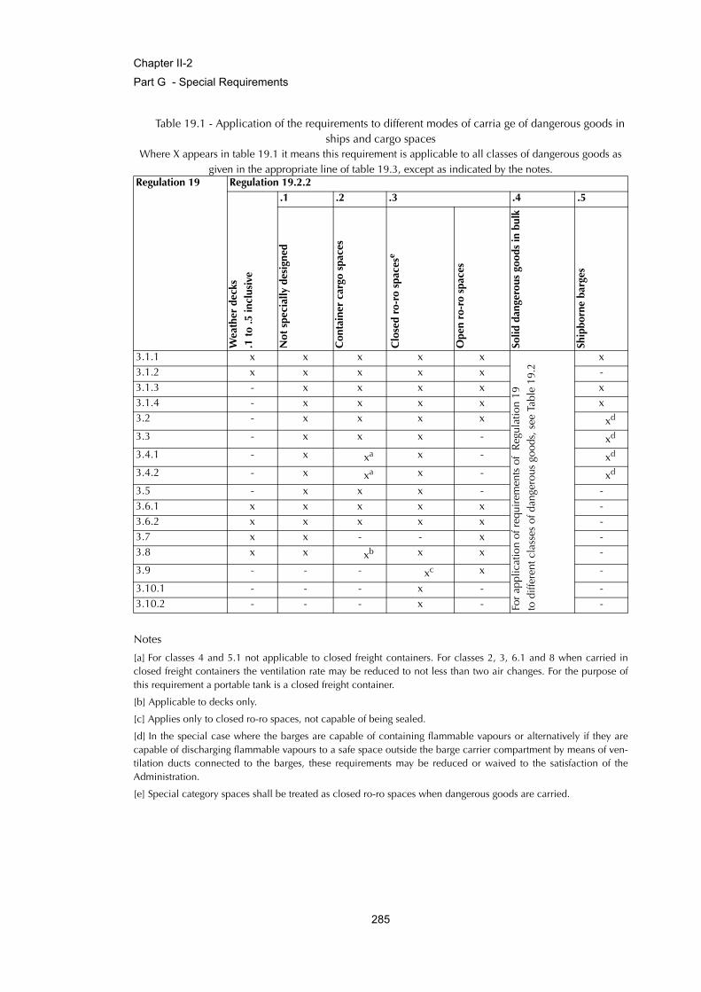
Chapter II-2
Part G - Special Requirements
Table 19.1 - Application of the requirements to different modes of carria ge of dangerous goods in ships and cargo spaces
Where X appears in table 19.1 it means this requirement is applicable to all classes of dangerous goods as given in the appropriate line of table 19.3, except as indicated by the notes.
Notes
[a] For classes 4 and 5.1 not applicable to closed freight containers. For classes 2, 3, 6.1 and 8 when carried inclosed freight containers the ventilation rate may be reduced to not less than two air changes. For the purpose ofthis requirement a portable tank is a closed freight container.
[b] Applicable to decks only.
[c] Applies only to closed ro-ro spaces, not capable of being sealed.
[d] In the special case where the barges are capable of containing flammable vapours or alternatively if they arecapable of discharging flammable vapours to a safe space outside the barge carrier compartment by means of ven-tilation ducts connected to the barges, these requirements may be reduced or waived to the satisfaction of theAdministration.
[e] Special category spaces shall be treated as closed ro-ro spaces when dangerous goods are carried.
Regulation 19 Regulation 19.2.2
Wea
ther
dec
ks
.1 t
o .5
incl
usiv
e
.1 .2 .3 .4 .5
Not
spe
cial
ly d
esig
ned
Con
tain
er c
argo
spa
ces
Clo
sed
ro-r
o sp
aces
e
Ope
n ro
-ro
spac
es
Solid
dan
gero
us g
oods
in b
ulk
Ship
born
e ba
rges
3.1.1 x x x x x
For
appl
icat
ion
of r
equi
rem
ents
of
Reg
ulat
ion
19to
diff
eren
t cla
sses
of d
ange
rous
goo
ds, s
ee T
able
19.
2
x3.1.2 x x x x x -3.1.3 - x x x x x3.1.4 - x x x x x3.2 - x x x x xd
3.3 - x x x - xd
3.4.1 - x xa x - xd
3.4.2 - x xa x - xd
3.5 - x x x - -3.6.1 x x x x x -3.6.2 x x x x x -3.7 x x - - x -3.8 x x xb x x -
3.9 - - - xc x -
3.10.1 - - - x - -3.10.2 - - - x - -
285
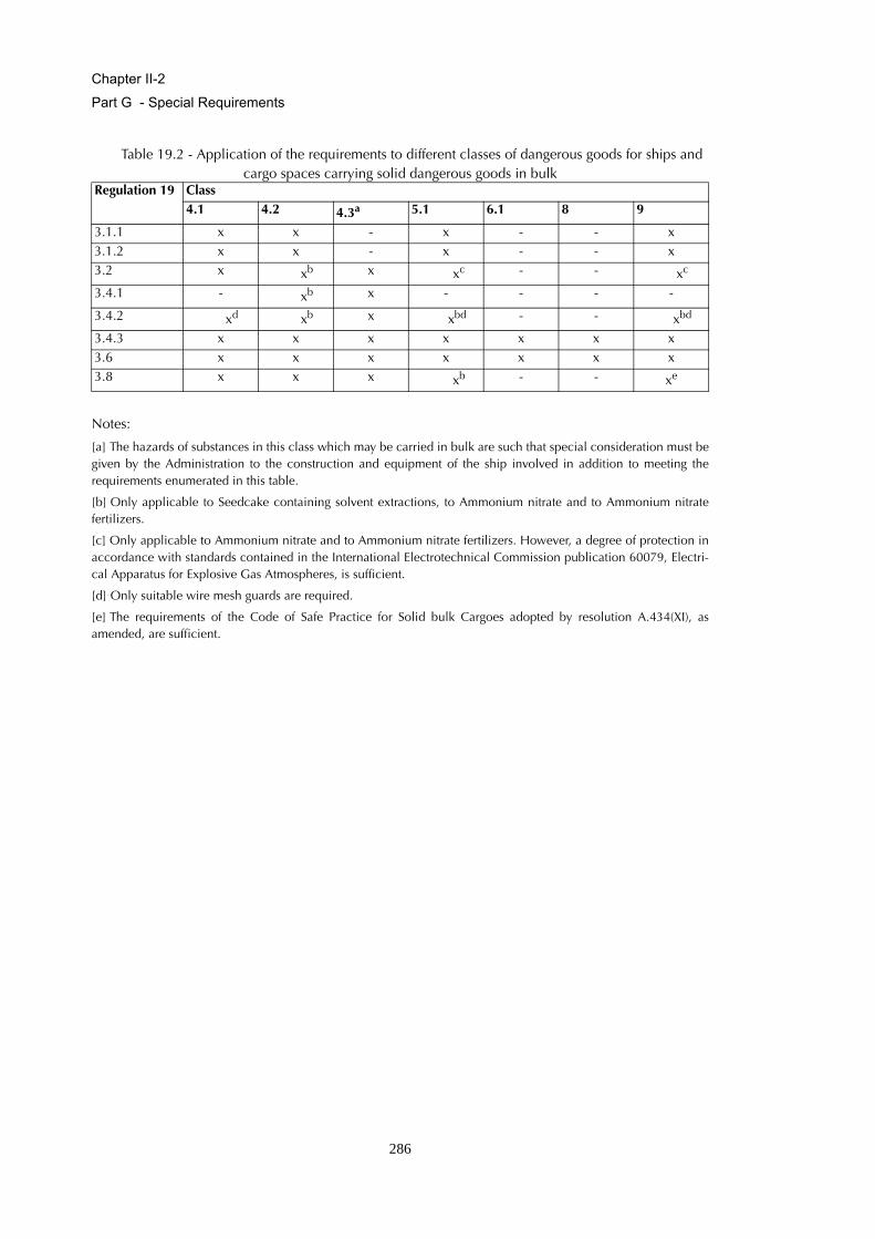
Chapter II-2
Part G - Special Requirements
Table 19.2 - Application of the requirements to different classes of dangerous goods for ships and cargo spaces carrying solid dangerous goods in bulk
Notes:
[a] The hazards of substances in this class which may be carried in bulk are such that special consideration must begiven by the Administration to the construction and equipment of the ship involved in addition to meeting therequirements enumerated in this table.
[b] Only applicable to Seedcake containing solvent extractions, to Ammonium nitrate and to Ammonium nitratefertilizers.
[c] Only applicable to Ammonium nitrate and to Ammonium nitrate fertilizers. However, a degree of protection inaccordance with standards contained in the International Electrotechnical Commission publication 60079, Electri-cal Apparatus for Explosive Gas Atmospheres, is sufficient.
[d] Only suitable wire mesh guards are required.
[e] The requirements of the Code of Safe Practice for Solid bulk Cargoes adopted by resolution A.434(XI), asamended, are sufficient.
Regulation 19 Class4.1 4.2 4.3a 5.1 6.1 8 9
3.1.1 x x - x - - x3.1.2 x x - x - - x3.2 x xb x xc - - xc
3.4.1 - xb x - - - -
3.4.2 xd xb x xbd - - xbd
3.4.3 x x x x x x x3.6 x x x x x x x3.8 x x x xb - - xe
286
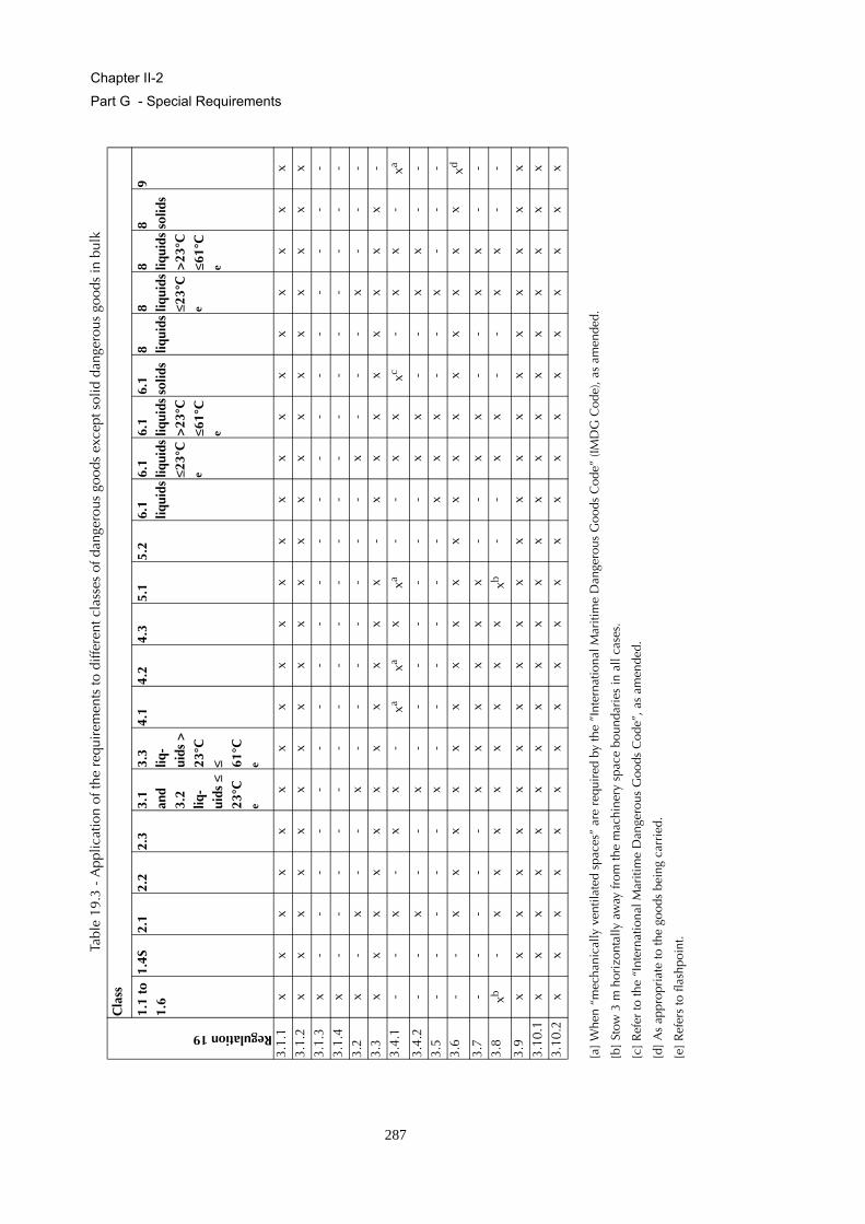
Chapter II-2
Part G - Special Requirements
Table
19.3
- A
pplic
atio
n of
the
requ
irem
ents
to d
iffer
ent c
lass
es o
f dan
gero
us g
oods
exc
ept s
olid
dan
gero
us g
oods
in b
ulk
[a]
Whe
n “m
echa
nica
lly v
entil
ated
spa
ces”
are
req
uire
d by
the
”Int
erna
tiona
l Mar
itim
e D
ange
rous
Goo
ds C
ode”
(IM
DG
Cod
e), a
s am
ende
d.
[b]
Stow
3 m
hor
izon
tally
aw
ay fr
om th
e m
achi
nery
spa
ce b
ound
arie
s in
all
case
s.
[c]
Ref
er to
the
“Int
erna
tiona
l Mar
itim
e D
ange
rous
Goo
ds C
ode”
, as
amen
ded.
[d]
As
appr
opri
ate
to th
e go
ods
bein
g ca
rrie
d.
[e]
Ref
ers
to fl
ashp
oint
.
Regulation 19
Cla
ss
1.1
to
1.6
1.4S
2.1
2.2
2.3
3.1
and
3.2
liq-
uids
≤
23°C
e
3.3
liq-
uids
>
23°C
≤ 61
°Ce
4.1
4.2
4.3
5.1
5.2
6.1
liqui
ds6.
1
liqui
ds≤2
3°C
e
6.1
liq
uids
>23
°C
≤61°
Ce
6.1
solid
s8 liq
uids
8 liqui
ds≤2
3°C
e
8 liqui
ds>
23°C
≤6
1°C
e
8 solid
s9
3.1.
1x
xx
xx
xx
xx
xx
xx
xx
xx
xx
xx
3.1.
2x
xx
xx
xx
xx
xx
xx
xx
xx
xx
xx
3.1.
3x
--
--
--
--
--
--
--
--
--
--
3.1.
4x
--
--
--
--
--
--
--
--
--
--
3.2
x-
x-
-x
--
--
--
-x
--
-x
--
-3.
3x
xx
xx
xx
xx
x x
-x
xx
xx
xx
x-
3.4.
1-
-x
-x
x -
xaxa
x xa
--
xx
xc-
xx
-xa
3.4.
2-
-x
--
x -
--
--
--
xx
--
xx
--
3.5
--
--
-x
--
--
--
xx
x-
-x
--
-3.
6-
-x
xx
xx
xx
xx
xx
xx
xx
xx
xxd
3.7
--
--
-x
xx
xx
x-
-x
x-
-x
x-
-3.
8xb
-x
xx
x x
xx
xxb
--
xx
--
xx
--
3.9
xx
xx
xx
x x
xx
xx
xx
xx
xx
xx
x3.
10.1
xx
xx
xx
xx
xx
xx
xx
xx
xx
xx
x3.
10.2
xx
xx
xx
xx
xx
xx
xx
xx
xx
xx
x
287
Chapter II-2
Part G - Special Requirements
Regulation 20Protection of vehicle, special category and ro-ro spaces
1 Purpose
The purpose of this regulation is to provide additional safety measures in order to address the fire safetyobjectives of this chapter for ships fitted with vehicle, special category and ro-ro spaces. For this pur-pose, the following functional requirements shall be met:
.1 fire protection systems shall be provided to adequately protect the ship from the fire haz-ards associated with vehicle, special category and ro-ro spaces;
.2 ignition sources shall be separated from vehicle, special category and ro-ro spaces; and
.3 vehicle, special category and ro-ro spaces shall be adequately ventilated.
2 General requirements
2.1 Application
In addition to complying with the requirements of regulations in parts B, C, D and E, as appropriate,vehicle, special category and ro-ro spaces shall comply with the requirements of this regulation.
2.2 Basic principles for passenger ships
2.2.1 The basic principle underlying the provisions of this regulation is that the main vertical zoningrequired by regulation 9.2 may not be practicable in vehicle spaces of passenger ships and, therefore,equivalent protection must be obtained in such spaces on the basis of a horizontal zone concept and bythe provision of an efficient fixed fire-extinguishing system. Based on this concept, a horizontal zone forthe purpose of this regulation may include special category spaces on more than one deck providedthat the total overall clear height for vehicles does not exceed 10 m.
2.2.2 The basic principle underlying the provisions of paragraph 2.2.1 are also applicable to ro-rospaces.
2.2.3 The requirements of ventilation systems, openings in "A" class divisions and penetrations in "A"class divisions for maintaining the integrity of vertical zones in this chapter shall be applied equally todecks and bulkheads forming the boundaries separating horizontal zones from each other and from theremainder of the ship.
288
Chapter II-2
Part G - Special Requirements
3 Precaution against ignition of flammable vapours in closed vehicle spaces, closed ro-ro spaces and special category spaces
3.1 Ventilation systems
3.1.1 Capacity of ventilation systems
There shall be provided an effective power ventilation system sufficient to give at least the following airchanges:
.1 Passenger ships
Special category spaces 10 air changes per hour
Closed ro-ro and vehicle space other thanspecial category spaces for ships carryingmore than 36 passengers 10 air changes per hour
Closed ro-ro and vehicle spaces other thanspecial category spaces for ships carrying notmore than 36 passengers 6 air changes per hour
.2 Cargo ships 6 air changes per hour
The Administration may require an increased number of air changes when vehicles arebeing loaded and unloaded.
3.1.2 Performance of ventilation systems
3.1.2.1 In passenger ships, the power ventilation system required in paragraph 3.1.1 shall be separatefrom other ventilation systems and shall be in operation at all times when vehicles are in such spaces.Ventilation ducts serving such cargo spaces capable of being effectively sealed shall be separated foreach such space. The system shall be capable of being controlled from a position outside such spaces.
3.1.2.2 In cargo ships, ventilation fans shall normally be run continuously whenever vehicles are onboard. Where this is impracticable, they shall be operated for a limited period daily as weather permitsand in any case for a reasonable period prior to discharge, after which period the ro-ro or vehicle spaceshall be proved gas-free. One or more portable combustible gas detecting instruments shall be carriedfor this purpose. The system shall be entirely separate from other ventilating systems. Ventilation ductsserving ro-ro or vehicle spaces shall be capable of being effectively sealed for each cargo space. Thesystem shall be capable of being controlled from a position outside such spaces.
3.1.2.3 The ventilation system shall be such as to prevent air stratification and the formation of airpockets.
289
Chapter II-2
Part G - Special Requirements
3.1.3 Indication of ventilation systems
Means shall be provided on the navigation bridge to indicate any loss of the required ventilatingcapacity.
3.1.4 Closing appliances and ducts
3.1.4.1 Arrangements shall be provided to permit a rapid shutdown and effective closure of the ventila-tion system from outside of the space in case of fire, taking into account the weather and seaconditions.
3.1.4.2 Ventilation ducts, including dampers, within a common horizontal zone shall be made of steel.In passenger ships, ventilation ducts that pass through other horizontal zones or machinery spaces shallbe “A-60” class steel ducts constructed in accordance with regulations 9.7.2.1.1 and 9.7.2.1.2.
3.1.5 Permanent openings
Permanent openings in the side plating, the ends or deckhead of the space shall be so situated that a firein the cargo space does not endanger stowage areas and embarkation stations for survival craft andaccommodation spaces, service spaces and control stations in superstructures and deckhouses abovethe cargo spaces.
3.2 Electrical equipment and wiring
3.2.1 Except as provided in paragraph 3.2.2, electrical equipment and wiring shall be of a type suita-
ble for use in an explosive petrol and air mixture.*
3.2.2 In case of other than special category spaces below the bulkhead deck, notwithstanding theprovisions in paragraph 3.2.1, above a height of 450 mm from the deck and from each platform forvehicles, if fitted, except platforms with openings of sufficient size permitting penetration of petrol gasesdownwards, electrical equipment of a type so enclosed and protected as to prevent the escape of sparksshall be permitted as an alternative on condition that the ventilation system is so designed and operatedas to provide continuous ventilation of the cargo spaces at the rate of at least ten air changes per hourwhenever vehicles are on board.
3.3 Electrical equipment and wiring in exhaust ventilation ducts
Electrical equipment and wiring, if installed in an exhaust ventilation duct, shall be of a type approvedfor use in explosive petrol and air mixtures and the outlet from any exhaust duct shall be sited in a safeposition, having regard to other possible sources of ignition.
* Refer to the recommendations of the International Electrotechnical Commission, in particular publication 60079.
290
Chapter II-2
Part G - Special Requirements
3.4 Other ignition sources
Other equipment which may constitute a source of ignition of flammable vapours shall not bepermitted.
3.5 Scuppers and discharges
Scuppers shall not be led to machinery or other spaces where sources of ignition may be present.
4 Detection and alarm
4.1 Fixed fire detection and fire alarm systems
Except as provided in paragraph 4.3.1, there shall be provided a fixed fire detection and fire alarm sys-tem complying with the requirements of the Fire Safety Systems Code. The fixed fire detection systemshall be capable of rapidly detecting the onset of fire. The type of detectors and their spacing and loca-tion shall be to the satisfaction of the Administration taking into account the effects of ventilation andother relevant factors. After being installed the system shall be tested under normal ventilation condi-tions and shall give an overall response time to the satisfaction of the Administration.
4.2 Sample extraction smoke detection systems
Except open ro-ro spaces, open vehicle spaces and special category spaces, a sample extraction smokedetection system complying with the requirements of the Fire Safety Systems Code may be used as analternative of the fixed fire detection and fire alarm system required in paragraph 4.1.
4.3 Special category spaces
4.3.1 An efficient fire patrol system shall be maintained in special category spaces. However, if anefficient fire patrol system is maintained by a continuous fire watch at all times during the voyage, afixed fire detection and fire alarm systems is not required.
4.3.2 Manually operated call points shall be spaced so that no part of the space is more than 20 mfrom a manually operated call point, and one shall be placed close to each exit from such spaces.
5 Structural protection
Notwithstanding the provisions of regulation 9.2.2, in passenger ships carrying more than 36 passen-gers, the boundary bulkheads and decks of special category spaces and ro-ro spaces shall be insulatedto "A-60" class standard. However, where a category (5), (9) and (10) space, as defined in regulation9.2.2.3, is on one side of the division the standard may be reduced to "A-0". Where fuel oil tanks arebelow a special category space or a ro-ro space, the integrity of the deck between such spaces, may bereduced to "A-0" standard.
291
Chapter II-2
Part G - Special Requirements
6 Fire -extinction
6.1 Fixed fire-extinguishing systems*
6.1.1 Vehicle spaces and ro-ro spaces which are not special category spaces and are capable ofbeing sealed from a location outside of the cargo spaces shall be fitted with a fixed gas fire-extinguish-ing system which shall comply with the provisions of the Fire Safety Systems Code, except that:
.1 if a carbon dioxide system is fitted, the quantity of gas available shall be at least sufficientto give a minimum volume of free gas equal to 45% of the gross volume of the largestsuch cargo space which is capable of being sealed, and the arrangements shall be such asto ensure that at least two thirds of the gas required for the relevant space shall be intro-duced within 10 min;
.2 any other fixed inert gas fire-extinguishing system or fixed high expansion foam fire-extin-guishing system may be fitted provided the Administration is satisfied that an equivalentprotection is achieved; and
.3 as an alternative, a system meeting the requirements of paragraph 6.1.2 may be fitted.
6.1.2 Ro-ro and vehicle spaces not capable of being sealed and special category spaces shall be fit-
ted with an approved fixed pressure water spraying system** for manual operation which shall protectall parts of any deck and vehicle platform in such spaces. Such water spray systems shall have:
.1 a pressure gauge on the valve manifold;
.2 clear marking on each manifold valve indicating the spaces served;
.3 instructions for maintenance and operation located in the valve room; and
.4 a sufficient number of drainage valves.
6.1.3 The Administration may permit the use of any other fixed fire-extinguishing system*** that hasbeen shown that it is not less effective by a full-scale test in conditions simulating a flowing petrol fire ina vehicle space or a ro-ro space in controlling fires likely to occur in such a space.
6.1.4 When fixed pressure water-spraying systems are provided, in view of the serious loss of stabilitywhich could arise due to large quantities of water accumulating on the deck or decks during the opera-tion of the fixed pressure water-spraying system, the following arrangements shall be provided:
* Refer to the Guidelines when approving alternative fixed water-based fire-fighting systems for use in special category spaces(MSC/Circ.914).** Refer to the Recommendation on fixed fire-extinguishing systems for special cargo spaces adopted by the Organization byresolution A.123(V).*** Refer to the Guidelines when approving alternative fixed water-based fire-fighting systems for use in special categoryspaces (MSC/Circ.914).
292
Chapter II-2
Part G - Special Requirements
.1 in passenger ships:
.1.1 in the spaces above the bulkhead deck, scuppers shall be fitted so as to ensure thatsuch water is rapidly discharged directly overboard;
.1.2.1 in ro-ro passenger ships discharge valves for scuppers, fitted with positive means ofclosing operable from a position above the bulkhead deck in accordance with therequirements of the International Convention on Load Lines in force, shall be keptopen while the ships are at sea;
.1.2.2 any operation of valves referred to in paragraph 6.1.4.1.2.1 shall be recorded in thelog-book;
.1.3 in the spaces below the bulkhead deck, the Administration may require pumping anddrainage facilities to be provided additional to the requirements of regulation II-1/21.In such case, the drainage system shall be sized to remove no less than 125% of thecombined capacity of both the water spraying system pumps and the requirednumber of fire hose nozzles. The drainage system valves shall be operable from out-side the protected space at a position in the vicinity of the extinguishing systemcontrols. Bilge wells shall be of sufficient holding capacity and shall be arranged atthe side shell of the ship at a distance from each other of not more than 40 m in eachwatertight compartment;
.2 in cargo ships, the drainage and pumping arrangements shall be such as to prevent thebuild-up of free surfaces. In such case, the drainage system shall be sized to remove noless than 125% of the combined capacity of both the water spraying system pumps andthe required number of fire hose nozzles. The drainage system valves shall be operablefrom outside the protected space at a position in the vicinity of the extinguishing systemcontrols. Bilge wells shall be of sufficient holding capacity and shall be arranged at theside shell of the ship at a distance from each other of not more than 40 m in each water-tight compartment. If this is not possible the adverse effect upon stability of the addedweight and free surface of water shall be taken into account to the extent deemed neces-
sary by the Administration in its approval of the stability information.* Such informationshall be included in the stability information supplied to the master as required by regula-tion II-1/22.
6.2 Portable fire extinguishers
6.2.1 Portable extinguishers shall be provided at each deck level in each hold or compartment wherevehicles are carried, spaced not more than 20 m apart on both sides of the space. At least one portablefire-extinguisher shall be located at each access to such a cargo space.
* Refer to the Recommendation on fixed fire-extinguishing systems for special cargo spaces adopted by the Organization byresolution A.123(V).
293
Chapter II-2
Part G - Special Requirements
6.2.2 In addition to the provision of paragraph 6.2.1, the following fire extinguishing appliances shallbe provided in vehicle, ro-ro and special category spaces intended for the carriage of motor vehicleswith fuel in their tanks for their own propulsion:
.1 at least three water-fog applicators; and
.2 one portable foam applicator unit complying with the provisions of the Fire Safety Sys-tems Code, provided that at least two such units are available in the ship for use in suchro-ro spaces.
294


![Fire Protection - SmartCockpit A319-320-321 [Fire Protection] Page 1. Airbus A319-320-321 [Fire Protection] ... [Fire Protection] Page 46. Airbus A319-320-321 [Fire Protection] Page](https://static.fdocuments.in/doc/165x107/5aaae6367f8b9a6c188ed0d4/fire-protection-a319-320-321-fire-protection-page-1-airbus-a319-320-321-fire.jpg)