Chapter HYDRAULIC JUMP - SKYSCRAPERS · Hydraulic jump formulas in terms of Froude-number 3.6....
24
OPEN CHANNEL HYDRAULICS FOR ENGINEERS ----------------------------------------------------------------------------------------------------------------------------------- ----------------------------------------------------------------------------------------------------------------------------------- Chapter 3: HYDRAULIC JUMP 46 Chapter HYDRAULIC JUMP _________________________________________________________________________ 3.1. Introduction 3.2. Specific energy 3.3. Depth of hydraulic jump 3.4. Types of hydraulic jump 3.5. Hydraulic jump formulas in terms of Froude-number 3.6. Submerged hydraulic jump _________________________________________________________________________ Summary In this chapter, the specific-energy concept is introduced and, then, the momentum principle is applied to open-channel flows. The hydraulic jump and its types are defined and classified. This chapter introduces how to determine the direct and submerged hydraulics jump; their characteristics are presented. Key words Momentum; hydraulic jump; specific energy; critical; Froude-number; direct and submerged jump _________________________________________________________________________ 3.1. INTRODUCTION The most common application of the momentum equation in open-channel flow deals with the analysis of the hydraulic jump. The rise in water level, which occurs during the transformation of the unstable rapid or supercritical flow to the stable tranquil or subcritical flow, is called hydraulic jump, manifesting itself as a standing wave. At the place, where the hydraulic jump occurs, a lot of energy of the flowing liquid is dissipated (mainly into heat energy). This hydraulic jump is said to be a dissipator of the surplus energy of the water. Beyond the hydraulic jump, the water flows with a greater depth, and therefore with a less velocity. The hydraulic jump has many practical and useful applications. Among them are the following: Reduction of the energy and velocity downstream of a dam or chute in order to minimize and control erosion of the channel bed. Raising of the downstream water level in irrigation channels. Acting as a mixing device for the addition and mixing of chemicals in industrial and water and wastewater treatment plants. In natural channels the hydraulic jump is also used to provide aeration of the water for pollution control purposes. However, before dealing with the hydraulic jump in detail, it is necessary to understand the principle of the so-called specific energy. We will apply this principle for explaining the hydraulic jump phenomenon. In the following the flow is supposed to be two-dimenssional.
Transcript of Chapter HYDRAULIC JUMP - SKYSCRAPERS · Hydraulic jump formulas in terms of Froude-number 3.6....

OPEN CHANNEL HYDRAULICS FOR ENGINEERS -----------------------------------------------------------------------------------------------------------------------------------
----------------------------------------------------------------------------------------------------------------------------------- Chapter 3: HYDRAULIC JUMP 46
Chapter HYDRAULIC JUMP
_________________________________________________________________________ 3.1. Introduction 3.2. Specific energy 3.3. Depth of hydraulic jump 3.4. Types of hydraulic jump 3.5. Hydraulic jump formulas in terms of Froude-number 3.6. Submerged hydraulic jump _________________________________________________________________________ Summary In this chapter, the specific-energy concept is introduced and, then, the momentum principle is applied to open-channel flows. The hydraulic jump and its types are defined and classified. This chapter introduces how to determine the direct and submerged hydraulics jump; their characteristics are presented. Key words Momentum; hydraulic jump; specific energy; critical; Froude-number; direct and submerged jump _________________________________________________________________________ 3.1. INTRODUCTION
The most common application of the momentum equation in open-channel flow deals with the analysis of the hydraulic jump. The rise in water level, which occurs during the transformation of the unstable �rapid� or supercritical flow to the stable �tranquil� or subcritical flow, is called hydraulic jump, manifesting itself as a standing wave. At the place, where the hydraulic jump occurs, a lot of energy of the flowing liquid is dissipated (mainly into heat energy). This hydraulic jump is said to be a dissipator of the surplus energy of the water. Beyond the hydraulic jump, the water flows with a greater depth, and therefore with a less velocity. The hydraulic jump has many practical and useful applications. Among them are the following:
Reduction of the energy and velocity downstream of a dam or chute in order to minimize and control erosion of the channel bed.
Raising of the downstream water level in irrigation channels. Acting as a mixing device for the addition and mixing of chemicals in industrial
and water and wastewater treatment plants. In natural channels the hydraulic jump is also used to provide aeration of the water for pollution control purposes.
However, before dealing with the hydraulic jump in detail, it is necessary to understand the principle of the so-called specific energy. We will apply this principle for explaining the hydraulic jump phenomenon. In the following the flow is supposed to be two-dimenssional.

OPEN CHANNEL HYDRAULICS FOR ENGINEERS -----------------------------------------------------------------------------------------------------------------------------------
----------------------------------------------------------------------------------------------------------------------------------- Chapter 3: HYDRAULIC JUMP 47
3.2. SPECIFIC ENERGY 3.2.1. Specific energy Fig. 3.1. Specific-energy head of a flowing liquid The specific-energy head, E, of a flowing liquid is defined as the energy head with respect to a datum plane, for instance passing through the bottom of the channel as shown in Fig. 3.1. Mathematically, the specific-energy head reads as:
2VE h
2g (3-1)
where h = depth of liquid flow, and V = mean velocity of the liquid. The specific-energy head can be written as:
2
s k
VE h E E
2g
where Es = h = static-energy head (also known as potential energy head), and
2 2
k 2
V qE
2g 2gh = kinetic-energy head (depth averaged),
with q = discharge per unit width. Plotting the specific-energy diagram for a channel (water depth h along the vertical axis), may conveniently be done by first drawing the two (independent) curves for static energy and kinetic energy and then adding the respective ordinates. The result is the required specific-energy head curve.
Fig. 3.2. Specific-energy head curve
E h
2V
2 g
E h2
h1 hc
2
k 2
qE
2gh Es = h
45
C
h
depth
E Emin
E vs h for q = constant

OPEN CHANNEL HYDRAULICS FOR ENGINEERS -----------------------------------------------------------------------------------------------------------------------------------
----------------------------------------------------------------------------------------------------------------------------------- Chapter 3: HYDRAULIC JUMP 48
Closer inspection shows, that the curve for the static-energy head (i.e. Es = h) is a straight line through the origin, at 45 with the horizontal. The curve for the kinetic-energy head
(i.e. 2
k 2
qE
2gh ), is a parabola (see Fig. 3.2.).
By adding the values of these two curves, at all the points, we get the specific-energy curve as shown in Fig. 3.2. 3.2.2. Critical depth and critical velocity
We can see in the specific-energy diagram Fig. 3.2 that the specific energy is minimum at point C. The depth of water in a channel, corresponding to the minimum specific energy (as at C in this case) is known as critical depth. This depth can be found by differentiating the specific-energy head equation and equating the result to zero. Or,
0dh
dE (3-2)
or, substituting 2V
E h2g
, we have:
0g2
Vh
dh
d 2
(3-3)
With V = h
q, where q is the constant discharge per unit width,
2
2
d qh 0
dh 2gh
0gh
q1
3
2
or gh
V
gh
1
h
q
gh
q1
2
2
2
3
2
g
Vh
2
(3-4)
Since the flow is (assumed to be) critical, the subcript c is added; therefore
g
Vh
2c
c (i) (3-5)
where hc = critical depth, and Vc = critical velocity. Replacing h by of hc and V by Vc in the specific-energy head equation, the minimum specific-energy head can be written as:
cc
cc
c
2C
cmin h2
3
2
hh
g2
ghh
g2
VhE
(3-6)
or the static-energy head becomes:
hc = minE3
2 (ii) (3-7)
and the kinetic-energy head: 2
ckc min min min
V 2 1E E E E
2g 3 3 (iii) (3-8)
OPEN CHANNEL HYDRAULICS FOR ENGINEERS -----------------------------------------------------------------------------------------------------------------------------------
----------------------------------------------------------------------------------------------------------------------------------- Chapter 3: HYDRAULIC JUMP 49
We have seen in Eq. (3-5) that
2
2cc
c
q
hVh
g g
or g
qh
23c
3
12
c g
qh
(3-9)
This is the equation for the critical depth, when the discharge per unit width through the channel is given. Thus, the critical velocity corresponding to the depth of the channel is:
Vc = ch
q (3-10)
Example 3.1: A channel, 6 m wide, is discharging 20 m3/s of water. Determine the critical depth and critical velocity, i.e. when the specific energy of the flowing water is minimum. Solution: Given: discharge: Q = 20 m3/s channel width: b = 6 m Discharge per unit width:
q = b
Q = 3.33 m2/s
Depth of water at minimum specific energy or critical depth:
hc = 3
12
g
q
= 1.04 m Ans.
and critical velocity:
Vc = ch
q = 3.20 m/s Ans.
3.2.3. Types of flows Depending on the critical depth as well as the real, occurring depth of water in a channel, three types of flow can be distinguished:
Tranquil flow If the depth of water, in the channel is greater than the critical depth, the flow is called tranquil or subcritical.
Critical flow
If the depth of water in the channel is critical, the flow is called critical. .
Rapid flow If the depth of water in the channel is smaller than the critical depth, the flow is called supercritical.
OPEN CHANNEL HYDRAULICS FOR ENGINEERS -----------------------------------------------------------------------------------------------------------------------------------
----------------------------------------------------------------------------------------------------------------------------------- Chapter 3: HYDRAULIC JUMP 50
Example 3.2: A channel of rectangular section, 7.5 m wide, is discharging water at a rate of 12 m3/s with an average velocity of 1.5 m/s. Find: (a) Specific-energy head of the flowing water, (b) Depth of water, when specific energy is minimum, (c) Velocity of water, when specific energy is minimum, (d) Minimum specific-energy head of the flowing water, (e) Type of flow. Solution: Given: width of the channel: b = 7.5 m discharge: Q = 12 m3/s
discharge per unit width: b
Qq 1.6 m2/s
average flow velocity: V = 1.5 m/s
depth of flowing water: V
qh = 1.067 m
Specific-energy head of the flowing water Let E = specific-energy head of the water.
Using the relation, g2
VhE
2
with the usual notations,
E = 1.182 m Ans. Depth of water, when specific energy is minimum Let hc = depth of water for minimum specific energy (i.e. the critical depth). Using the relation,
3
12
c g
qh
hc = 0.639 m Ans. Velocity of water, when specific energy is minimum Let Vc = velocity of water, when specific energy is minimum (i.e. the critical velocity). Using the relation,
c
c h
qV
Vc = 2.5 m/sec Ans. Minimum specific-energy head of the flowing water Let Emin = minimum specific-energy head of the flowing water.
Using the relation, g2
VhE
2c
cmin with the usual notations,
Emin = 0.958 m Ans. Type of flow Since the depth of water (1.067 m) is larger than the critical depth (0.639 m), the flow is tranquil or subcritical. Ans.
OPEN CHANNEL HYDRAULICS FOR ENGINEERS -----------------------------------------------------------------------------------------------------------------------------------
----------------------------------------------------------------------------------------------------------------------------------- Chapter 3: HYDRAULIC JUMP 51
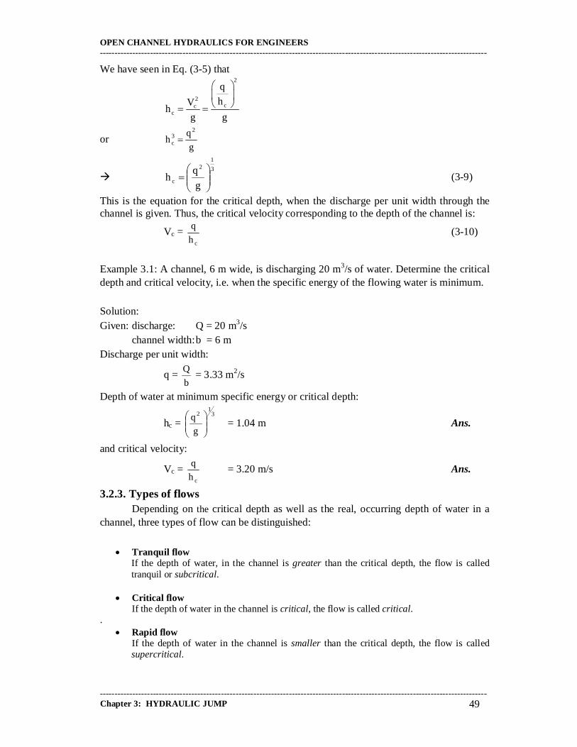
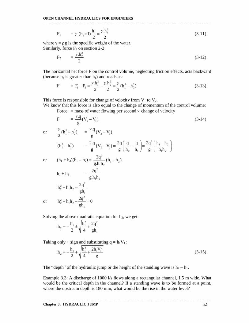
3.3. DEPTH OF HYDRAULIC JUMP 3.3.1. Concept We can see in the specific-energy diagram (Fig. 3.2) that for a given specific energy E, there are two possible depths h1 and h2. The depth h1 is smaller than the critical depth, and h2 is greater than the critical depth. We also know that, when the water depth is smaller than the critical depth, the flow is called a tranquil or subcritical flow. But when the depth is greater than the critical depth, the flow is called a rapid or supercritical flow. It has been experimentally found, that the rapid flow is an unstable type of flow, and does not continue on the downstream side. The transformation from �rapid� flow into �tranquil� flow occurs by means of a so-called �hydraulic jump�. A counterclockwise roller �rides� continously up the surface of the jump, entraining air and contributing to the general complexity of the internal flow patterns, as illustrated in Fig. 3.3. Turbulence is produced at the boundary between the incoming jet and the roller. The kinetic energy of the turbulence is rapidly dissipated along with the mean flow energy in the downstream direction, so that the turbulence kinetic energy is small at the end of the jump. This complex flow situation is ideal for the application of the momentum equation, because precise mathematical description of the internal flow pattern is not possible. 3.3.2. Water rise in hydraulic jump Consider two sections, on the upstream and downstream side of a jump, as shown in Fig. 3.3.
Fig. 3.3. Hydraulic jump Let 1 - 1 = section on the upstream side of the hydraulic jump, 2 - 2 = section on the downstream side of the hydraulic jump, h1 = depth of flow at section 1 - 1, V1 = flow velocity at section 1 - 1, h2, V2 = corresponding values at section 2 - 2, and q = discharge per unit width,
b
Qq , where Q = total discharge and b = width of channel and hydraulic jump
q = h1V1 = h2V2 Now consider the control volume of water between the sections 1-1 and 2-2, and apply the law of conservation of momentum. Force F1 on section 1-1:
1 2
1 2
h2 h1
V1
V2
F1 F2
OPEN CHANNEL HYDRAULICS FOR ENGINEERS -----------------------------------------------------------------------------------------------------------------------------------
----------------------------------------------------------------------------------------------------------------------------------- Chapter 3: HYDRAULIC JUMP 52
F1 = 2
1 11
h .h.(h 1)
2 2
(3-11)
where = g is the specific weight of the water. Similarly, force F2 on section 2-2:
F2 = 22.h
2
(3-12)
The horizontal net force F on the control volume, neglecting friction effects, acts backward (because h2 is greater than h1) and reads as:
F = 2 2
2 21 21 2 1 2
.h .hF F (h h )
2 2 2
(3-13)
This force is responsible for change of velocity from V1 to V2. We know that this force is also equal to the change of momentum of the control volume: Force = mass of water flowing per second change of velocity
F = 2 1
.q(V V )
g
(3-14)
or 2 21 2(h h )
2
= 2 1
.q(V V )
g
2 21 2(h h ) =
21 2
2 12 1 1 2
2.q 2q q q 2q h h(V V )
g g h h g h h
or (h1 + h2)(h1 � h2) = 2
1 21 2
2q(h h )
g.h h
h1 + h2 = 2
1 2
2q
g.h h
2
22 1 2
1
2qh h h
gh
or 2
22 1 2
1
2qh h h 0
gh
Solving the above quadratic equation for h2, we get:
2 2
1 12
1
h h 2qh
2 4 gh
Taking only + sign and substituting q = h1V1 :
2 2
1 1 1 12
h h 2h Vh
2 4 g (3-15)
The �depth� of the hydraulic jump or the height of the standing wave is h2 � h1. Example 3.3: A discharge of 1000 l/s flows along a rectangular channel, 1.5 m wide. What would be the critical depth in the channel? If a standing wave is to be formed at a point, where the upstream depth is 180 mm, what would be the rise in the water level?
OPEN CHANNEL HYDRAULICS FOR ENGINEERS -----------------------------------------------------------------------------------------------------------------------------------
----------------------------------------------------------------------------------------------------------------------------------- Chapter 3: HYDRAULIC JUMP 53
Solution: Given: discharge: Q = 1000 l/s = 1m3/s channel width: b = 1.5 m upstream depth: h1= 180 mm Discharge per unit width:
q = b
Q = 0.67 m2/s
Critical depth in the channel:
hc = 3
12
g
q
= 0.358 m Ans.
Let h2 be the depth of the flow on the downstream side of the standing wave or hydraulic jump.
2 2
1 12
1
h h 2qh
2 4 gh = 0.63 m = 630 mm
Rise in water level h: h = h2 � h1 = 450 mm Ans. 3.3.3. Energy loss due to hydraulic jump The loss of energy head due to the occurrence of the hydraulic jump is the difference between the specific-energy heads at sections 1-2 and 2-2. Mathematically,
E = 2 2
1 21 2 1 2
V VE E h h
2g 2g
(3-16)
Example 3.4. A rectangular channel, 6 m wide, discharges 1200 l/s of water into a 6 m wide apron, with zero slope, with a mean velocity of 6 m/s. What is the height of the jump? How much power is absorbed in the jump? Solution: Given: channel width: b = 6 m
discharge: Q = 1200 l/s = 1.2 m3/s mean velocity: V = 6 m/s
Q
qb
= 0.2 m2/s
12 3
c
qh
g
= 0.16 m
1cc
qV
h = 1.25 m/s
V1 > V1c : supercritical flow occurrence of hydraulic jump.

OPEN CHANNEL HYDRAULICS FOR ENGINEERS -----------------------------------------------------------------------------------------------------------------------------------
----------------------------------------------------------------------------------------------------------------------------------- Chapter 3: HYDRAULIC JUMP 54
Height of hydraulic jump Depth of water on the upstream side of the jump:
h1 = bV
Q
1 = 0.033 m
2 2
1 1 1 12
h h 2h Vh
2 4 g = 0.476 m
Height of hydraulic jump hjump hjump = h2 � h1 = 0.443 m Ans. Energy absorbed in the jump Drop of specific-energy head: E = E1 � E2
We know that due to the continuity of the discharge: V1h1 = V2h2
or V2 = 1 1
2
V h
h = 0.42 m/s
Now using the relation:
2 2
1 21 2 1 2
V VE E h h
2g 2g
= 1.384 m Ans.
Dissipation of power in hydraulic jump: 1 2P gQ E E = 16.3 kW Ans.
3.3.4. Hydraulic jump features The following features are associated with the transition from supercritical to subcritical flow:
Highly turbulent flow with significantly dynamic velocity and pressure components;
Pulsations of both pressure and velocity, and wave development downstream of the jump;
Two-phase flow due to air entrainment; Erosive pattern due to increased macro-scale vortex development; Sound generation and energy dissipation as a result of turbulence production.
A hydraulic jump thus includes several features by which excess mechanical energy may be dissipated into heat. The action of energy dissipation may even be amplified by applying energy dissipators. These problems will be discussed in Chapter 6.
OPEN CHANNEL HYDRAULICS FOR ENGINEERS -----------------------------------------------------------------------------------------------------------------------------------
----------------------------------------------------------------------------------------------------------------------------------- Chapter 3: HYDRAULIC JUMP 55
3.4. TYPES OF HYDRAULIC JUMP 3.4.1. Criterion for a critical state-of-flow
The effect of gravity upon the state of flow is represented by a ratio of inertial
forces to gravity forces. This ratio is given by the Froude number, defined as:
gL
VFr (3-17)
where V is the mean velocity of flow in m/s, g is the acceleration of gravity in m/s2, and L
is a characteristic length in m.
The critical state-of-flow has been defined in Section (3.2.2.) as the condition for which the
Froude number is equal to unity, i.e. Fr = 1, with L = h, or:
V gh (3-18)
A more common definition is, that it is the state of flow at which the specific energy is a
minimum for a given discharge. When the depth of flow is greater than the critical depth,
the flow velocity is smaller than the critical velocity for the given discharge, and at this
case, the Froude number is smaller than 1, hence, the flow is subcritical. When the depth
of flow is smaller than the critical depth, or the Froude number is larger than 1, the flow is
supercritical.
A theoretical criterion for critical flow may be developed from this definition as follows.
Since V = Q/A, the equation for the specific-energy head in a channel of small or zero
slope can be written as:
2
2
QE h
2gA (3-19)
Differentiating with respect to y, noting that Q is a constant, yields
2 2
3
dE Q dA V dA1 . 1 .
dh gA dh gA dh (3-20)

OPEN CHANNEL HYDRAULICS FOR ENGINEERS -----------------------------------------------------------------------------------------------------------------------------------
----------------------------------------------------------------------------------------------------------------------------------- Chapter 3: HYDRAULIC JUMP 56
Fig. 3.4. Specific-energy head curve
The differential wet cross-sectional area dA near the free surface as indicated in Fig. 3.4. is
equal to W.dh, where W is the width of the cross-sectional area considered.
Now dA/dh = W. By definition, the so-called hydraulic depth, D, is D = A/W, i.e. the ratio
of the channel flow area A and its top width W; so the above equation becomes:
2 2dE V W V
1 1dh gA gD
(3-21)
At the critical state-of-flow the (specific) energy is a minimum, or dE/dh = 0. The above
equation, then gives:
2
D
g2
V 2
(3-22)
This is the criterion for critical flow, which states that at the critical state-of-flow, the
velocity head is equal to half the hydraulic depth. The above equation may also be written
as:
Fr1gD
V (3-23)
which means Fr = 1; this is the definition of critical flow given previously. If the above
criterion is (to be) used in a problem, the following conditions must be satisfied:
45 for a channel of zero or small slope
dA
W h
hc
h1 hc
h2
h
dh
g2
V 2
2
D
critical state
subcritical flow range
supercritical flow range
discharge = Q greater than Q less than Q E
h
A

OPEN CHANNEL HYDRAULICS FOR ENGINEERS -----------------------------------------------------------------------------------------------------------------------------------
----------------------------------------------------------------------------------------------------------------------------------- Chapter 3: HYDRAULIC JUMP 57
(1) flow parallel or gradually varied;
(2) channel of small slope; and
(3) energy coefficient assumed to be unity.
If the energy coefficient is not assumed to be unity, the critical flow criterion is:
2
D
g2
V 2
(3-24)
where is an (energy) correction coefficient accounting for using the depth-avegared flow
velocity instead of the (full) velocity distribution.
For a channel of large slope angle and velocity distribution coefficient , the criterion for
critical flow can easily be proved to be:
2
cosD
g2
V 2 (3-25)
where D is the hydraulic depth of the water area normal to the channel bottom.
In this case, the Froude-number may be defined as:
cosgD
VFr (3-26)
It should be noted that the coefficient of a channel section actually varies with depth. In
the above derivation, however, the coefficient is assumed to be constant; therefore, the
resulting equation is not absolutely exact.
Example 3.5: For a trapezoidal channel with base width b = 6.0 m and side slope m = 2,
calculate the critical depth of flow if Q = 17 m3/s.
Solution:
Given: width of base: b = 6.0 m side slope: m = 2
flow rate: Q = 17 m3/s. Critical depth ?
Flow area: A = (b +mh)h = (6 + 2h)h
Top width: W = b + 2mh = 6 + 4h
Hydraulic depth: 3 h hA
DW 3 2h

OPEN CHANNEL HYDRAULICS FOR ENGINEERS -----------------------------------------------------------------------------------------------------------------------------------
----------------------------------------------------------------------------------------------------------------------------------- Chapter 3: HYDRAULIC JUMP 58
and velocity: Q 17
VA 2(3 h)h
Substituting of the above in Eq. (3-22) yields
217 /(6 2h)h (3 h)h
g 3 2h
Simplifying,
7.4(3 + 2h) = [(3 + h)h]3
By trial and error, the critical depth is approximately
h = hc = 0.84 m Ans.
and the corresponding critical velocity is
c
c c
QV
b 2h h
= 2.6 m/s Ans.
3.4.2. Types of hydraulic jump
Hydraulic jumps on a horizontal bottom can occur in several distinct forms. Based
on the Froude number of the supercritical flow directly upstream of the hydraulic jump,
several types can be distinguished (see Table 3.1).
It should be noted that the ranges of the Froude number given in Table 3.1 for the various types of jump are not clear-cut but overlap to a certain extent depending on local conditions. Given the simplicity of channel geometry and the significance in the design of stilling
basins, the classical hydraulic jump received considerable attention during the last sixty
years. Of particular interest were:
The ratio of sequent depths, that is the flow depths upstream and downstream of
the jump, and
The length of jump, measured from the toe to some tailwater zone.

OPEN CHANNEL HYDRAULICS FOR ENGINEERS -----------------------------------------------------------------------------------------------------------------------------------
----------------------------------------------------------------------------------------------------------------------------------- Chapter 3: HYDRAULIC JUMP 59
Table 3.1: Froude number and types of jump (Ven Te Chow, 1973)
Froude Jump type Illustration Description
1 � 3
undular
The water surface shows undulations
3 � 6
weak
A series of small rollers develop on the
surface of the jump, but the downstream
water surface remains smooth. The
velocity throughout is fairly uniform, and
the energy loss is low
6 - 20 oscillating There is an oscillating jet entering the
jump from bottom to surface and back
again with no periodicity. Each
oscillation produces a large wave of
irregular period which, very commonly in
canals, can travel for meters doing
unlimited damage to earthen banks and
rip-raps
20 � 80 steady The downstream extremity of the surface
roller and the point at which the high-
velocity jet tends to leave the flow occur
at practically the same vertical section.
The action and position of this jump are
least sensitive to variation in tailwater
depth. The jump is well-balanced and the
performance is at its best. The energy
dissipation ranges from 45 to 70%.
> 80 strong The high-velocity jet grabs intermittent
slugs of water rolling down the front face
of the jump, generating waves
downstream, and a rough surface can
prevail. The jump action is rough but
effective since the energy dissipation may
reach 85%.
A hydraulic jump may occur in four different distinct forms, if the undular jump as
previously discussed is excluded. The classification of classical jumps may be given only
in terms of the approaching Froude number, if jumps with inflow depths smaller than h1 =
1 to 2 cm are excluded. According to Bradley and Peterka (1957), classical hydraulic
jumps may occur as presented in Fig. 3.5.

OPEN CHANNEL HYDRAULICS FOR ENGINEERS -----------------------------------------------------------------------------------------------------------------------------------
----------------------------------------------------------------------------------------------------------------------------------- Chapter 3: HYDRAULIC JUMP 60
Fig. 3.5. �Classical� forms of hydraulic jump
Pre-jump: (Fig. 3.5.a) if 1.7 < Fr < 2.5. A series of small rollers develop on the surface at Fr = 1.7, which is slightly intensified for increasing Fr-number. A pre-jump presents no particular problems for a stilling basin as the water surface is quite smooth, and the velocity distribution in the tailwater is fairly uniform. However, the efficiency of the jump is low from an energetic point of view.
Transition jump: (Fig. 3.5.b) if 2.5 < Fr < 4.5. This type of jump has a pulsating action. The entering jet oscillates heavily from the bottom to the surface without regular period. Each oscillation produces a large wave of irregular period, which may cause very undesirable bank erosion. Transition jumps occur often in low head structures.
Stabilised jump: (Fig. 3.5.c) if 4.5 < Fr < 9. These jumps have the best performance since they have a limited tailwater wave action, relatively high energy dissipation, and a compact and stable appearance. The point where the high velocity current leaves the bottom coincides nearly with the roller end section. Efficiencies between 45% and 70% may be obtained.
Choppy jump: (Fig. 3.5.d) if Fr > 9. At such high Fr-number, the high velocity jet is no more able to remain on the bottom. Slugs of water rolling down the front face of the jump intermittently fall into the high velocity jet, and generate additional tailwater waves. The surface of the jump is usually very rough, and contains a considerable amount of spray.
(a) pre-jump
(b) transition jump
(c) stabilised jump
(d) choppy jump
OPEN CHANNEL HYDRAULICS FOR ENGINEERS -----------------------------------------------------------------------------------------------------------------------------------
----------------------------------------------------------------------------------------------------------------------------------- Chapter 3: HYDRAULIC JUMP 61
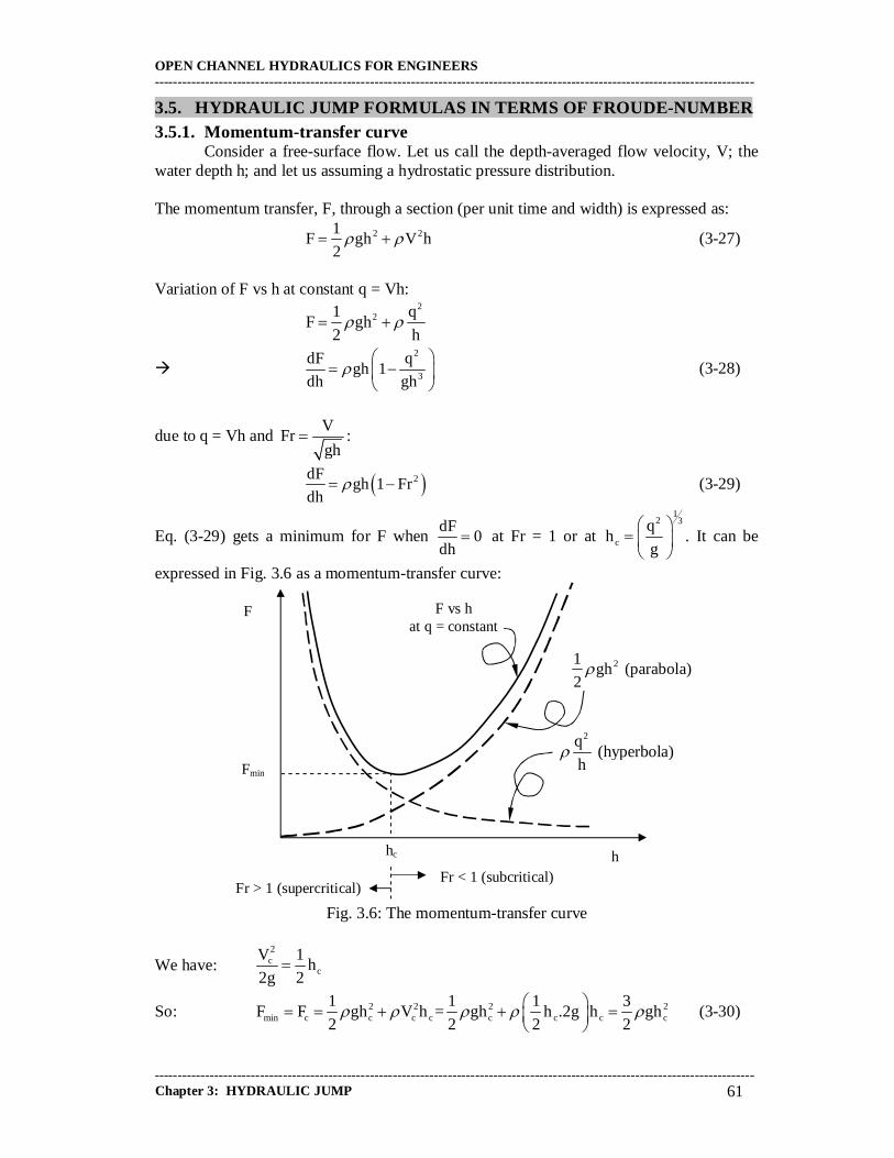
3.5. HYDRAULIC JUMP FORMULAS IN TERMS OF FROUDE-NUMBER 3.5.1. Momentum-transfer curve
Consider a free-surface flow. Let us call the depth-averaged flow velocity, V; the water depth h; and let us assuming a hydrostatic pressure distribution. The momentum transfer, F, through a section (per unit time and width) is expressed as:
2 21F gh V h
2 (3-27)
Variation of F vs h at constant q = Vh:
2
21 qF gh
2 h
2
3
dF qgh 1
dh gh
(3-28)
due to q = Vh and V
Frgh
:
2dFgh 1 Fr
dh (3-29)
Eq. (3-29) gets a minimum for F when dF
0dh
at Fr = 1 or at
12 3
c
qh
g
. It can be
expressed in Fig. 3.6 as a momentum-transfer curve:
Fig. 3.6: The momentum-transfer curve
We have: 2c
c
V 1h
2g 2
So: 2 2 2 2min c c c c c c c c
1 1 1 3F F gh V h = gh h .2g h gh
2 2 2 2
(3-30)
F
h
F vs h at q = constant
Fmin
hc
2q (hyperbola)
h
21gh (parabola)
2
Fr < 1 (subcritical) Fr > 1 (supercritical)

OPEN CHANNEL HYDRAULICS FOR ENGINEERS -----------------------------------------------------------------------------------------------------------------------------------
----------------------------------------------------------------------------------------------------------------------------------- Chapter 3: HYDRAULIC JUMP 62
3.5.2. Direct hydraulic jump When the rapid change in the depth of flow is from a low stage to a high stage, the
result is usually an abrupt rise of the water surface (see Fig. 3.7, in which the vertical scale is exaggerated). This local phenomenon is known as the hydraulic jump. It frequently occurs in a canal downstream of a regulating sluice, at the foot of a spillway, or at the place where a steep channel slope suddenly turns flat.
Fig.3.7. Hydraulic jump interpreted by specific-energy head and momentum-transfer curves
If the jump is low, that is, if the change in depth is small, the water will not rise obviously and abruptly, but will pass from the low to the high stage through a series of undulations, gradually diminishing in size. Such a low jump is called an undular jump. If the jump is high, that is, when the change in depth is great, the jump is called a direct jump. The direct jump involves a relatively large amount of energy loss through dissipation in the turbulent body of water in the jump. Consequently, the energy content in the flow after the jump is appreciably less than before the jump. 3.5.3. The initial depth and the sequent depth
It may be noted that the depth before the jump is always less than the depth after the jump. The depth before the jump is called the initial depth h1 and that after the jump is called the sequent depth h2. The initial and sequent depths h1 and h2 are shown on the specific-energy head curve (Fig. 3.7). They should be distinguished from the alternative depths h1 and h2�, which are the two possible depths for the same specific energy. The initial and sequent depths are the actual depths before and after a jump. The specific-energy head E1 at the initial depth h1 is greater than the specific-energy head E2 at the sequent depth h2 by an amount equal to the energy loss E. If there were no energy losses, the initial and sequent depths would become identical with the alternative depths (in a prismatic channel). We can determine a relationship between the initial depth and the sequent depth of a hydraulic jump on a horizontal floor in a rectangular channel. The external forces of friction and the weight effect of the water in a hydraulic jump on a horizontal floor are negligible, because the jump takes place along a relatively short
1 2 energy-head line
critical depth
sequent depth
initial depth
E1 E2 hc
hc
h1 h1
h2 h2
E h2�
alternative depth of h1
alternative depth of h2�
E2 E1
E
C
C� P1 P1�
P2
P2�
P2�
F1=F2 F E
h h
0 0
specific-energy head curve momentum-transfer curve hydraulic jump
Q

OPEN CHANNEL HYDRAULICS FOR ENGINEERS -----------------------------------------------------------------------------------------------------------------------------------
----------------------------------------------------------------------------------------------------------------------------------- Chapter 3: HYDRAULIC JUMP 63
distance and the slope angle of the floor is zero. The momentum transfers through section 1 and 2 in Fig. 3.7, respectively, i.e. before and after the jump, can therefore be considered equal; that is,
222
2
111
2
AzgA
QAz
gA
Q (3-31)
For a rectangular channel of width b,
Q = V1A1 = V2A2; A1 = bh1 and A2 = bh2;
2
hz and
2
hz 2
21
1 .
Substituting these relations and 1
11
gh
VFr in the above equation and simplifying, it can be
derived:
0Fr2h
h)12Fr(
h
h 21
1
221
3
1
2
(3-32)
Factoring: 01h
hFr2
h
h
h
h
1
221
1
2
2
1
2
From which it follows: 0Fr2h
h
h
h 21
1
2
2
1
2
(3-33)
The solution of this quadratic equation is
2
11
2 Fr8112
1
h
h (3-34)
Obviously the solution with the minus sign is not possible (it would give a negative 1
2
h
h).
Thus,
1Fr81
2
1
h
h 21
1
2 (3-35a)
For a given Froude number Fr1 of the approaching flow, the ratio of the sequent depth to the initial depth is given by the above equation. Likewise it can be derived:
1Fr81
2
1
h
h 22
2
1 (3-35b)
with 2
22
gh
VFr

OPEN CHANNEL HYDRAULICS FOR ENGINEERS -----------------------------------------------------------------------------------------------------------------------------------
----------------------------------------------------------------------------------------------------------------------------------- Chapter 3: HYDRAULIC JUMP 64
3.5.4. Energy loss We continue considering that the energy-head loss, EL, is due to the violent
turbulent mixing and dissipation that occur within the jump itself. Thus, the energy equation reads as follows:
L
22
2
21
1 Eg2
Vh
g2
Vh (3-36)
The dimensionless energy-head loss, 1
L
h
E, can be obtained as:
2
2
12
1
1
2
1
L
h
h1
2
Fr
h
h1
h
E (3-37)
where, for given value of Fr1, the value of 1
2
h
h is used from equation (3-35).
It should be understood that, with applying Eq. (3.35), the momentum principle is used in this solution, because the hydraulic jump involves a high amount of internal energy losses which cannot be evaluated in the energy equation. This joint use of the specific-energy head curve and the momentum-transfer curve helps to determine graphically the energy loss involved in the hydraulic jump for a given approaching flow. For the given approaching depth h1, points P1 and P1� are located on the momentum-transfer curve and the specific energy curve, respectively (Fig. 3.7.). The point P1� gives the initial energy content E1. Draw the vertical line, passing through the point P1 and intercepting the upper limb of the momentum-transfer curve at point P2, which gives the sequent depth h2. Then, draw a horizontal line passing through the point P2 and intercepting the specific-energy head curve at point P2�, which gives the �energy content� E2 after the jump. The energy-head loss in the jump is then equal to E1 � E2, represented by EL. After some elaboration it can be derived:
21
312
21L hh4
hhEEE
(3-38)
The ratio 1
L
E
E is known as the relative energy- head loss.
Example 3.6: A vertical sluice gate with an opening of 0.67 m produces a downstream jet with a depth of 0.40 m when installed in a long rectangular channel, 5.0 m wide, conveying a steady discharge of 20 m3/s. It is assumed that the flow downstream of the gate eventually returns to a uniform flow depth of 2.5 m. (a) Verify that a hydraulic jump occurs. (b) Calculate the energy-head loss in the jump.
(c) If the energy-head loss through the gate is 0.05 g2
V 2II , calculate the depth upstream of
the gate and the force on the gate. Solution: Given: gate opening: ho = 0.67 m downstream jet depth: hII = 0.40 m
channel wide: W = 5.0 m discharge: Q = 20 m3/s sequent depth: h2 = 2.5 m
Jump occurs? Energy head loss EL? Upstream depth hI? Force on the gate?

OPEN CHANNEL HYDRAULICS FOR ENGINEERS -----------------------------------------------------------------------------------------------------------------------------------
----------------------------------------------------------------------------------------------------------------------------------- Chapter 3: HYDRAULIC JUMP 65
The sluice gate control and the hydraulic jump can be sketched as presented in the figure below: (a) If a hydraulic jump is to form, the required initial depth, h1, must be greater than the jet depth, hII. Velocity of flow in the downstream section:
2
2 Wh
Q
A
QV = 1.6 m/s
Froude number: 22
2
VFr
gh = 0.323
Initial depth:
1Fr81
2
hh 2
22
1 = 0.443 m
Because h1 > hII, therefore a jump will form. Ans. (b) Apply the energy-head loss formula:
21
312
21L hh4
hhEEE
= 1,965 m Ans.
(c) Apply the energy equation from section I to section II:
g2
V05.0
g2
Vh
g2
Vh
2II
2II
II
2I
I
where II
I h
4
Wh
QV and
2II
IIII
Q VV 10 m/s, so 5.097 m
Wh 2g
whence hI = 5.73 m Ans. Let Fx the gate reaction per unit width. Apply the momentum equation to the control volume between section I and section II:
2 2
2 2I IIx I I II II
gh ghF V h V h
2 2
(Note that the force due to the friction head loss through the gate is implicitly included in the above equation since this effects the value of hI) Whence Fx = 123 kN/m Ans.
gate
h2
h1 ho
EL
2IV
2g
2IIV
2g
hII
hI
I II
Fx

OPEN CHANNEL HYDRAULICS FOR ENGINEERS -----------------------------------------------------------------------------------------------------------------------------------
----------------------------------------------------------------------------------------------------------------------------------- Chapter 3: HYDRAULIC JUMP 66
3.5.5. Efficiency The ratio of the specific energy after the jump to that before the jump is defined as the efficiency of the jump. It can be shown that the efficiency is (Ven Te Chow, 1973):
21
21
21
23
21
1
2
Fr2Fr8
1Fr41Fr8
E
E
(3-39)
This equation indicates that the efficiency of a hydraulic jump is a dimensionless function, depending only on the Froude number of the approaching flow. The relative specific-
energy-head loss is equal to 1
2
E
E1 ; this also is a dimensionless function of Fr1.
3.5.6. Height of jump The difference between the depths after and before the jump is the height of the jump, or hj = h2 � h1. Expressing each term as a ratio with respect to the initial specific energy, yields
1
1
1
2
1
j
E
h
E
h
E
h (3-40)
where 1
j
E
his the relative height,
1
1
E
his the relative initial depth, and
1
2
E
his the relative
sequent depth. All these ratios can be shown to be a dimensionless function of Fr1. For example (Ven Te Chow, 1973):
2Fr
3Fr81
E
h2
1
21
1
j
(3-41)
3.5.7. Length of jump The length of the hydraulic jump may be defined as the distance measured from the front face of the jump to a point on the surface immediately downstream of the roller as indicated in Fig. 3.8.:
Fig.3.8. Length of hydraulic jump The length of the jump cannot be determined easily by theory, but it has been investigated experimentally by many hydraulicians. The experimental data on the length of the jump can be plotted conveniently with the Froude number Fr1 against the dimensionless ratio
12 hh
Lj
,
1
j
h
L or 2
j
h
L . The plot of Fr1 vs. 1
j
h
L is probably the best, for the resulting curve
can be best defined by the data. For practical purposes, however, the plot of Fr1 vs 2
j
h
L is
desirable, because the resulting curve then shows regularity or a fairly flat portion for the range of well-established jumps.
Lj
V1
h2 h1
roller V2

OPEN CHANNEL HYDRAULICS FOR ENGINEERS -----------------------------------------------------------------------------------------------------------------------------------
----------------------------------------------------------------------------------------------------------------------------------- Chapter 3: HYDRAULIC JUMP 67
We also may apply some experimental formulas by Russian hydraulicians: Pavolovski�s formula (1940), for a rectangular channel, if Fr1> 10:
Lj = 2.5 (1.9h2 � h1) (3-42)
Picalov�s formula (1954) for a rectangular channel, if Fr1> 10: Lj = 11 Fr21h4 (3-43)
If 3 < Fr < 400 in a rectangular channel, we may use Ivadian�s formula (1955):
Lj =
21
312
1
1
hh4
hh.
Fr
Fr108 (3-44)
In case of a trapezoidal channel, we use Ivadian�s formula (1955):
Lj =
B
bB41h5 2 (3-45)
where B and b are the free water-surface widths of the wetted cross-sections before and after the jump, respectively. 3.6. SUBMERGED HYDRAULIC JUMP 3.6.1. Definition
A submerged hydraulic jump, or shortly called submerged jump, is defined as the jump where the toe is covered by water and the atmosphere has no direct access to the body of the jump. As a result, a submerged jump entrains much less air than the non-submerged jump. A submerged jump may typically develop behind gates as sketched in Fig. 3.8.
Fig. 3.8. Gate flow with non-submerged jump (a) and submerged jump (b)
For low tailwater, a free-surface flow is generated behind the gate lip and the approaching flow to the jump is supercritical. However, when increasing the tailwater level, the toe of the jump moves towards the gate lip and attaches to it at transitional flow. Further increase of the tailwater level makes the jump extremely rough. The jump entrains air over limited periods of time only, and the body of the jump moves against the gate to separate after a short while. The transition from non-submerged to submerged gate flow is highly dynamic and pulsating, and should be avoided in view of the development of large dynamic pressures. If the tailwater is raised further, the jump changes gradually to a submerged jet. This is characterised by low-noise development, low-pulsating flow and continuous flow
(a) Non-submerged jump (b) Submerged jump
gate gate
OPEN CHANNEL HYDRAULICS FOR ENGINEERS -----------------------------------------------------------------------------------------------------------------------------------
----------------------------------------------------------------------------------------------------------------------------------- Chapter 3: HYDRAULIC JUMP 68
appearance. The energy dissipation reduces with the degree of submergence; however, a highly submerged jump may not be used as an efficient energy dissipator. 3.6.2. Flow in submerged jump
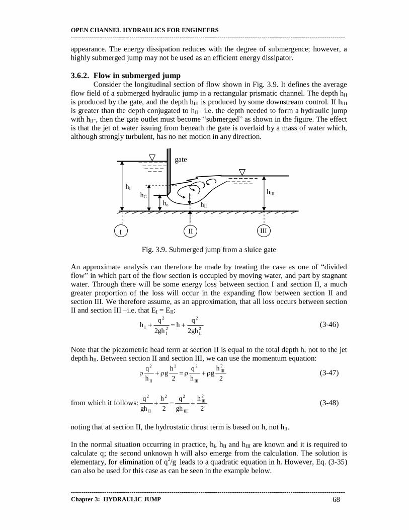
Consider the longitudinal section of flow shown in Fig. 3.9. It defines the average flow field of a submerged hydraulic jump in a rectangular prismatic channel. The depth hII is produced by the gate, and the depth hIII is produced by some downstream control. If hIII is greater than the depth conjugated to hII �i.e. the depth needed to form a hydraulic jump with hII-, then the gate outlet must become �submerged� as shown in the figure. The effect is that the jet of water issuing from beneath the gate is overlaid by a mass of water which, although strongly turbulent, has no net motion in any direction.
Fig. 3.9. Submerged jump from a sluice gate An approximate analysis can therefore be made by treating the case as one of �divided flow� in which part of the flow section is occupied by moving water, and part by stagnant water. Through there will be some energy loss between section I and section II, a much greater proportion of the loss will occur in the expanding flow between section II and section III. We therefore assume, as an approximation, that all loss occurs between section II and section III �i.e. that EI = EII:
2II
2
2I
2
Igh2
qh
gh2
qh (3-46)
Note that the piezometric head term at section II is equal to the total depth h, not to the jet depth hII. Between section II and section III, we can use the momentum equation:
2
hg
h
q
2
hg
h
q 2III
III
22
II
2
(3-47)
from which it follows: 2
h
gh
q
2
h
gh
q 2III
III
22
II
2
(3-48)
noting that at section II, the hydrostatic thrust term is based on h, not hII. In the normal situation occurring in practice, hI, hII and hIII are known and it is required to calculate q; the second unknown h will also emerge from the calculation. The solution is elementary, for elimination of q2/g leads to a quadratic equation in h. However, Eq. (3-35) can also be used for this case as can be seen in the example below.
gate
hIII
ho hII
hI
I II
hG
III
OPEN CHANNEL HYDRAULICS FOR ENGINEERS -----------------------------------------------------------------------------------------------------------------------------------
----------------------------------------------------------------------------------------------------------------------------------- Chapter 3: HYDRAULIC JUMP 69
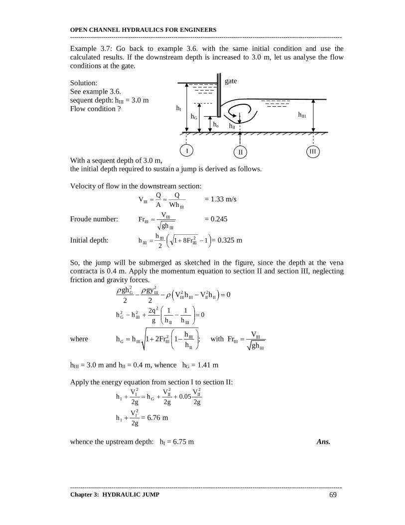
Example 3.7: Go back to example 3.6. with the same initial condition and use the calculated results. If the downstream depth is increased to 3.0 m, let us analyse the flow conditions at the gate. Solution: See example 3.6. sequent depth: hIII = 3.0 m Flow condition ? With a sequent depth of 3.0 m, the initial depth required to sustain a jump is derived as follows. Velocity of flow in the downstream section:
III
III Wh
Q
A
QV = 1.33 m/s
Froude number: III
IIIIII
gh
VFr = 0.245
Initial depth:
1Fr81
2
hh 2
IIIIII
III = 0.325 m
So, the jump will be submerged as sketched in the figure, since the depth at the vena contracta is 0.4 m. Apply the momentum equation to section II and section III, neglecting friction and gravity forces.
2 2
2 2G IIIIII III II II
gh gyV h V h 0
2 2
0h
1
h
1
g
q2hh
IIIII
22III
2G
where 2 III IIIG III III III
II III
h Vh h 1 2Fr 1 ; with Fr
h gh
hIII = 3.0 m and hII = 0.4 m, whence hG = 1.41 m Apply the energy equation from section I to section II:
g2
V05.0
g2
Vh
g2
Vh
2II
2II
G
2I
I
g2
Vh
2I
I = 6.76 m
whence the upstream depth: hI = 6.75 m Ans.
gate
hIII
ho hII
hI
I II
hG
III


![Hydraulic Jump and Resultant Flow Choking in a Circular Sewer … · the hydraulic jump in a circular pipe [12,17]. Let alone the hydraulic jump in a circular pipe of steep slope.](https://static.fdocuments.in/doc/165x107/5e6bfa6b4a9ff14e3c46306d/hydraulic-jump-and-resultant-flow-choking-in-a-circular-sewer-the-hydraulic-jump.jpg)