Chapter 6 Time Division Switching - Shandong …course.sdu.edu.cn/G2S/eWebEditor/uploadfile/...6.1...
75
Chapter 6 Time Division Switching School of Information Science and Engineering, Shandong University Associate Prof., Deqiang Wang
Transcript of Chapter 6 Time Division Switching - Shandong …course.sdu.edu.cn/G2S/eWebEditor/uploadfile/...6.1...
Chapter 6Time Division Switching
School of Information Science and Engineering, Shandong UniversityAssociate Prof., Deqiang Wang
Outline
Introduction Basic Time Division Space SwitchingBasic Time Division Time SwitchingTime Multiplexed Space SwitchingTime Multiplexed Time SwitchingCombination SwitchingThree-stage Combination SwitchingN-Stage Combination Switching
Introduction
Review of Space Division SwitchingSingle-stage: Dedicated switching element for a specific pair of inlet-outlet.Multi-stage: Switching elements sharedby inlet-outlet pairs.A Common feature: Switching elements involved in a connection serve only onespeech circuit to pass through continuous speech signal.
Introduction
Time Division SwitchingFeatures of PAM/PCM signal
Discrete in time domain Transmission of PAM/PCM signal
MultiplexingPeriodical time slots
For PAM/PCM signals, it is possible for a number of active speech circuits to share a single switching element, and therefore reduce the number of switching elements significantly.
6.1 Basic time division space switching
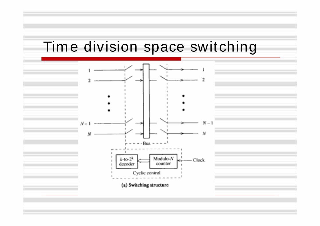
NxN time division space switchingArchitectureAnalog time division space switching (PAM)
Analog bus is employedDigital time division space switching (PCM)
Digital bus is employedSwitching capacity (simultaneous conversations supported)
SC=125/tsNote: The sampling frequency is 8kHz, the corresponding sampling interval is 125 microseconds, ts in microsecond is the time to setup a connection and transfer the sample value.
Time division space switching
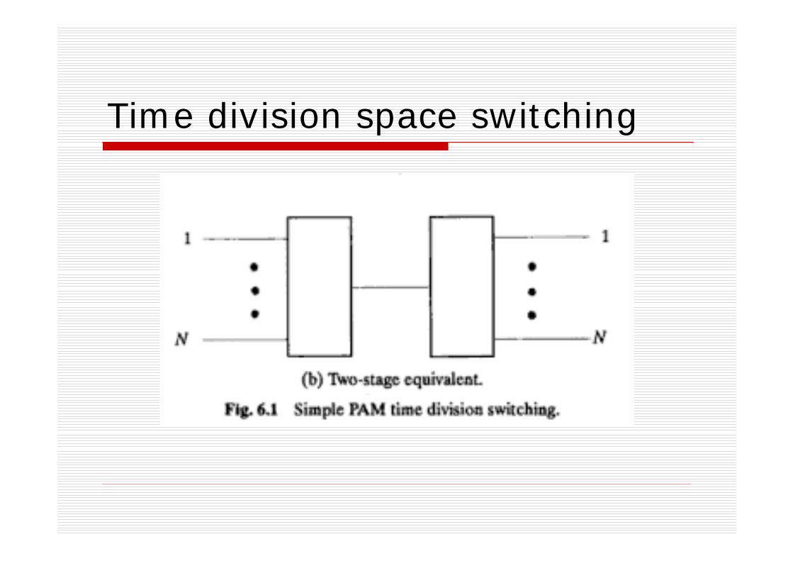
Time division space switching
Control mechanisms
Cyclic control in synchronismInput-controlled / Input-drivenOutput-controlled / Output-driven

Control mechanisms
Cyclic control in synchronismCyclically select/scan inlets and outletsFixed one-to-one correspondenceOne switching element shared by all connectionsA modulo-N counter & a k-to-2k decoder
Remarks:There is no switching.It lacks full availability.
2logk N= ⎡ ⎤⎢ ⎥

Cyclic control in synchronism
nonblocking
Control mechanisms
Input-controlled / Input-drivenThe control on the input side works in a cyclic manner.The control on output side is memory-based and changes synchronously with the input side.Full availability is obtained by using the programmable feature of the memory.
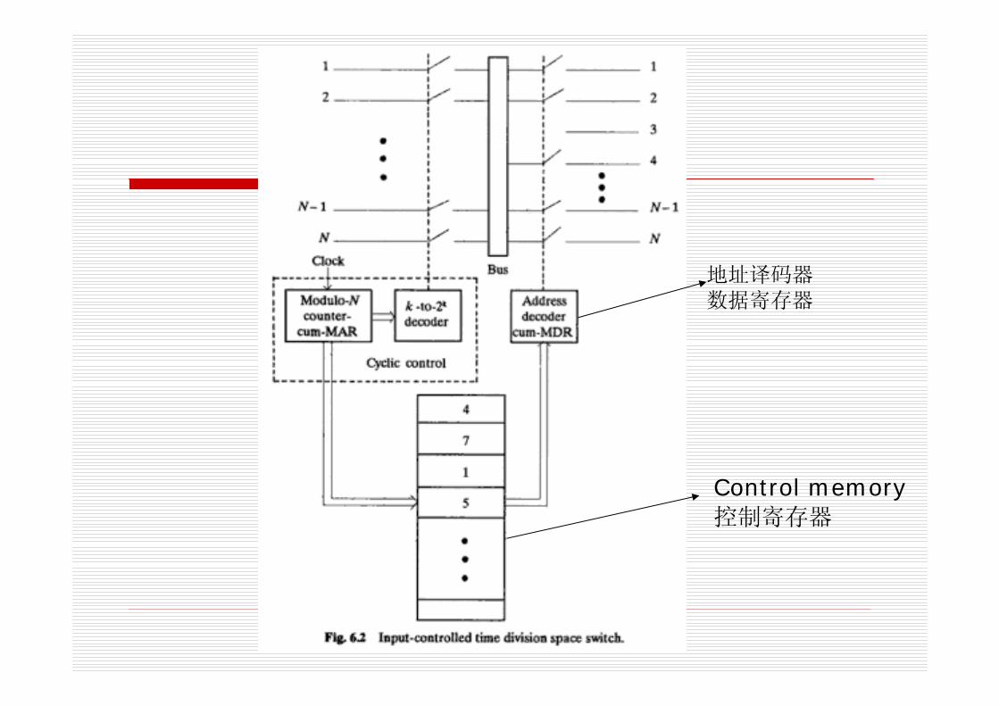
Control memory控制寄存器
地址译码器数据寄存器
Control mechanisms
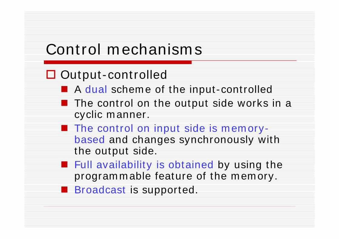
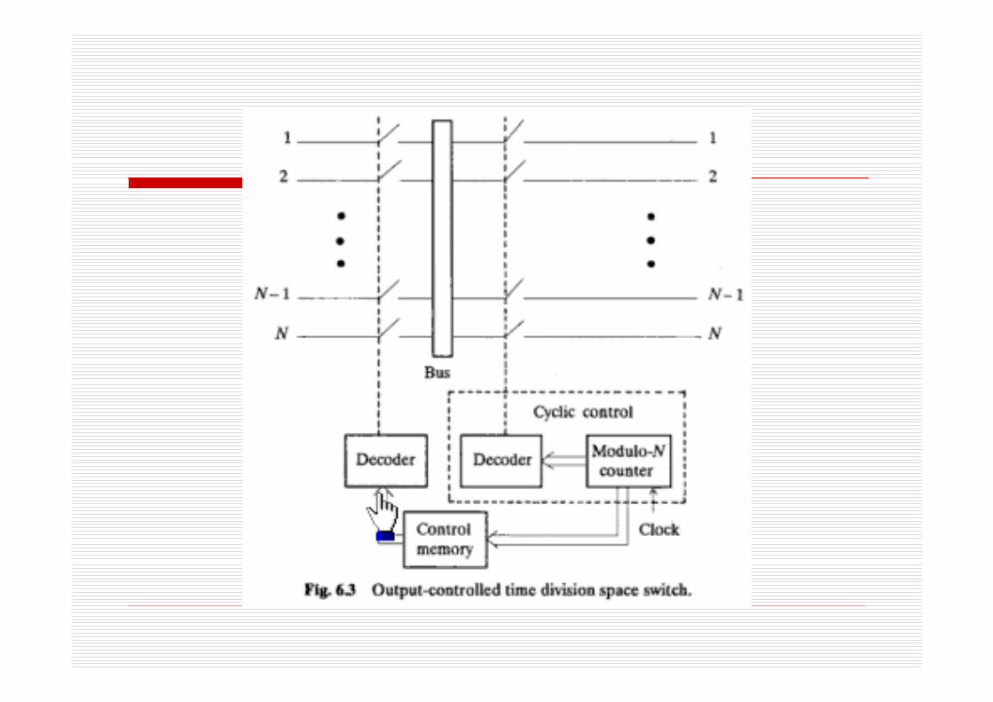
Output-controlledA dual scheme of the input-controlledThe control on the output side works in a cyclic manner.The control on input side is memory-based and changes synchronously with the output side.Full availability is obtained by using the programmable feature of the memory.Broadcast is supported.
Remarks on both input-controlled and output-controlled
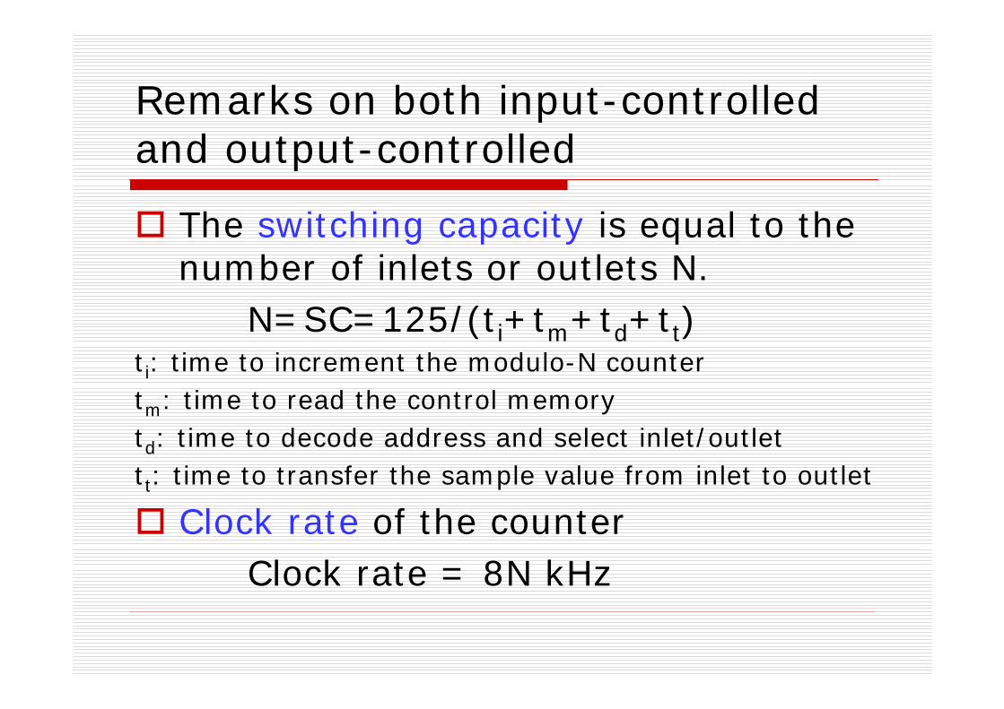
The switching capacity is equal to the number of inlets or outlets N.
N=SC=125/(ti+tm+td+tt)ti: time to increment the modulo-N countertm: time to read the control memorytd: time to decode address and select inlet/outlettt: time to transfer the sample value from inlet to outlet
Clock rate of the counterClock rate = 8N kHz
Remarks on both input-controlled and output-controlled
Configuration for bi-direction transferScheme 1: two independent buses used, one for each direction.Scheme 2: one bus used, time division multiplexing for two-way transfer.
Folded networkBoth input-controlled and output-controlled can be used to support folded network connections.

Remarks on both input-controlled and output-controlled
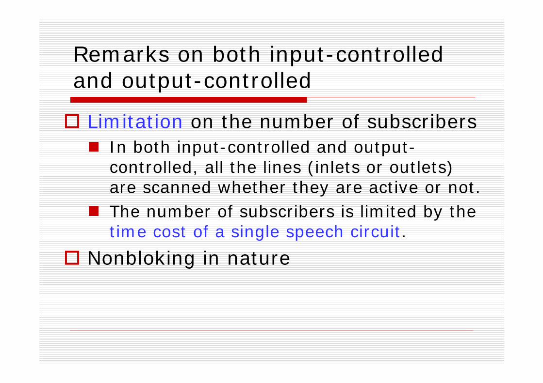
Limitation on the number of subscribersIn both input-controlled and output-controlled, all the lines (inlets or outlets) are scanned whether they are active or not.The number of subscribers is limited by the time cost of a single speech circuit.
Nonbloking in nature
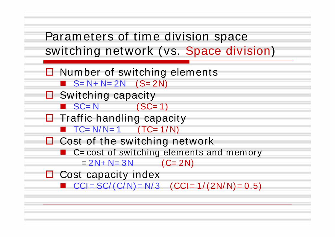
Parameters of time division space switching network (vs. Space division)
Number of switching elementsS=N+N=2N (S=2N)
Switching capacitySC=N (SC=1)
Traffic handling capacityTC=N/N=1 (TC=1/N)
Cost of the switching networkC=cost of switching elements and memory
=2N+N=3N (C=2N)Cost capacity index
CCI=SC/(C/N)=N/3 (CCI=1/(2N/N)=0.5)
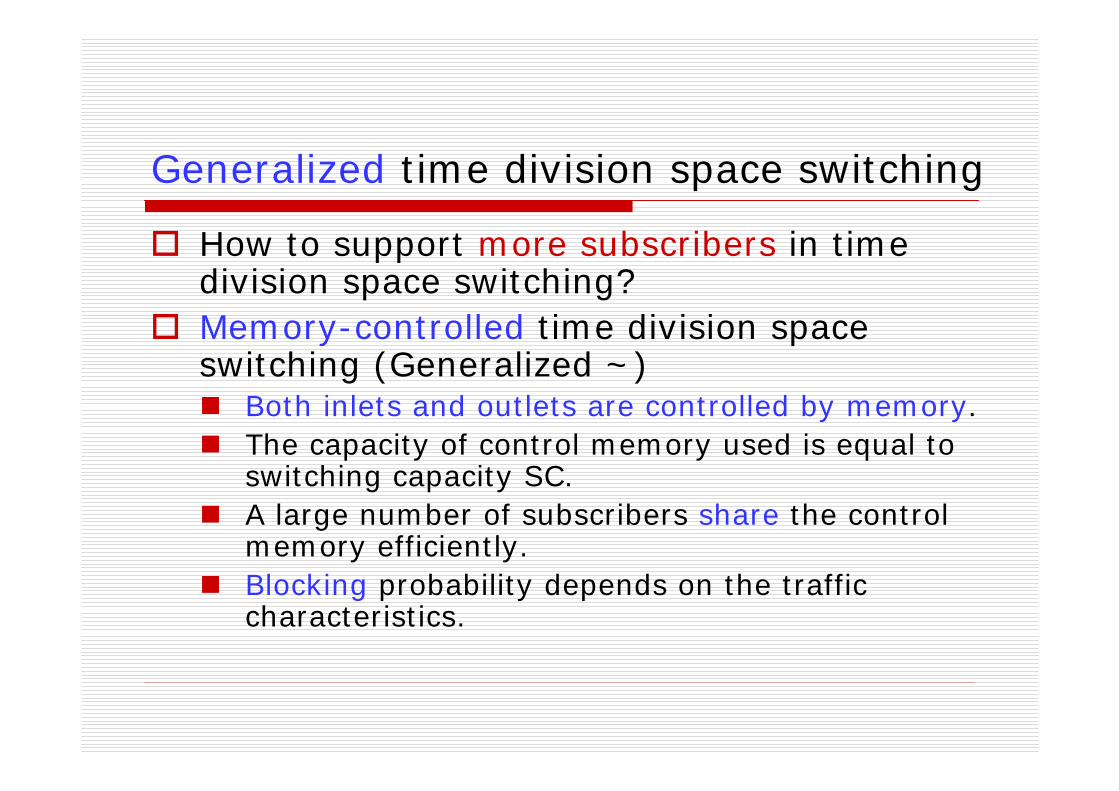
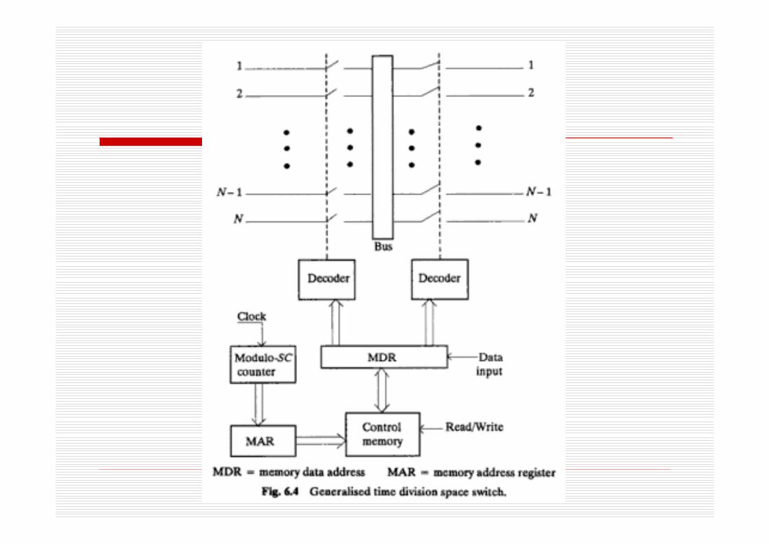
Generalized time division space switching
How to support more subscribers in time division space switching?Memory-controlled time division space switching (Generalized ~)
Both inlets and outlets are controlled by memory.The capacity of control memory used is equal to switching capacity SC.A large number of subscribers share the control memory efficiently.Blocking probability depends on the traffic characteristics.
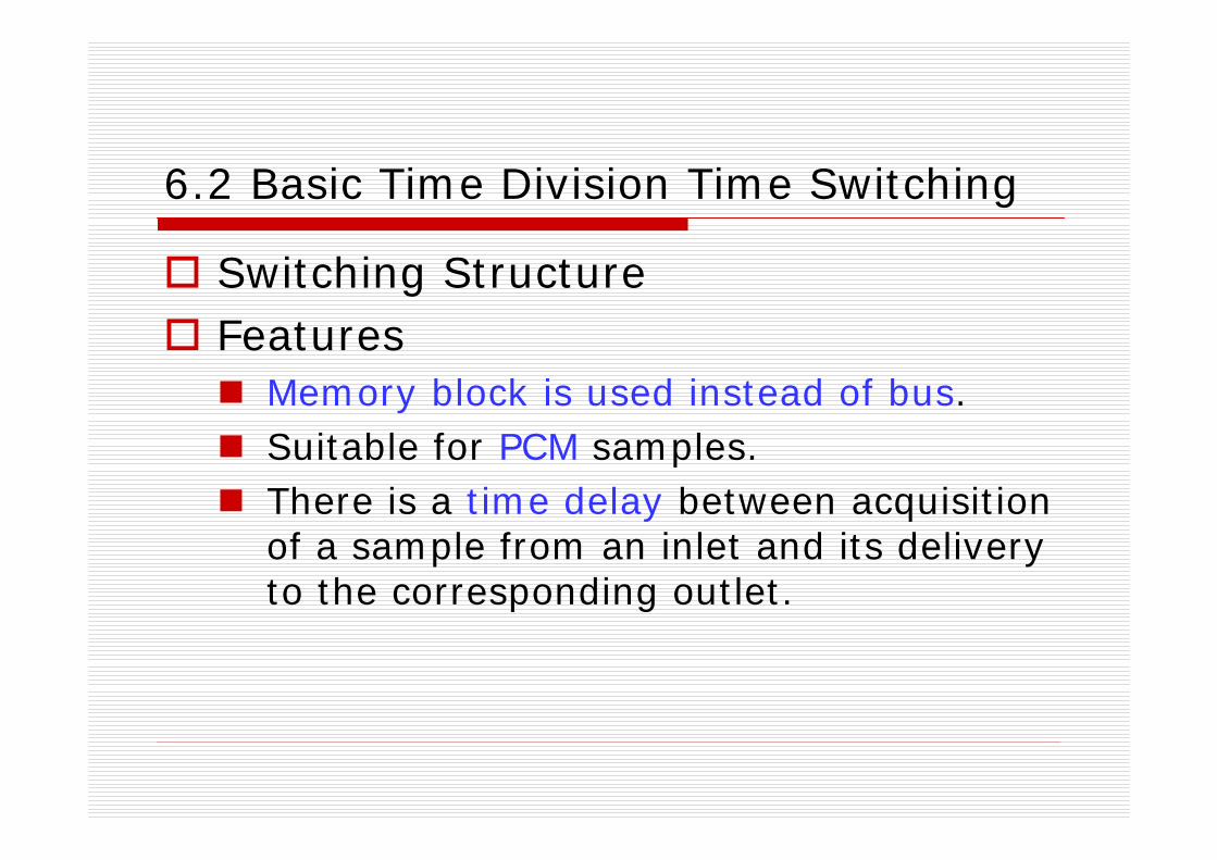
6.2 Basic Time Division Time Switching
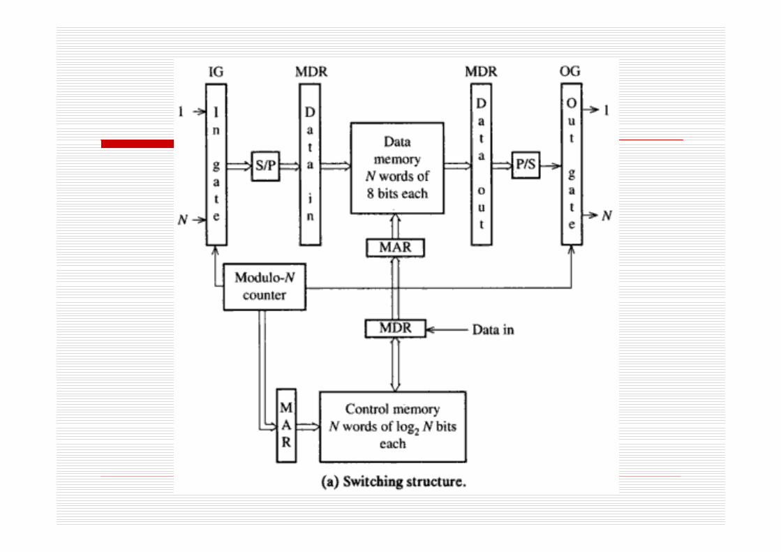
Switching StructureFeatures
Memory block is used instead of bus.Suitable for PCM samples.There is a time delay between acquisition of a sample from an inlet and its delivery to the corresponding outlet.

Switching Control Methods
Sequential write/Random readRandom write/Sequential readRadom input/Random output

Switching Control Methods
Sequential write/Random readThe inlets and outlets are both scanned sequentially.The samples from inlets are written into data memory sequentially.The samples are read from data memory randomly and then delivered to outlets.
Switching Control Methods
Random write/Sequential readThe inlets and outlets are both scanned sequentially.The samples from inlets are written into data memory randomly.The samples are read from data memory sequentially and then delivered to outlets.
Switching Control Methods
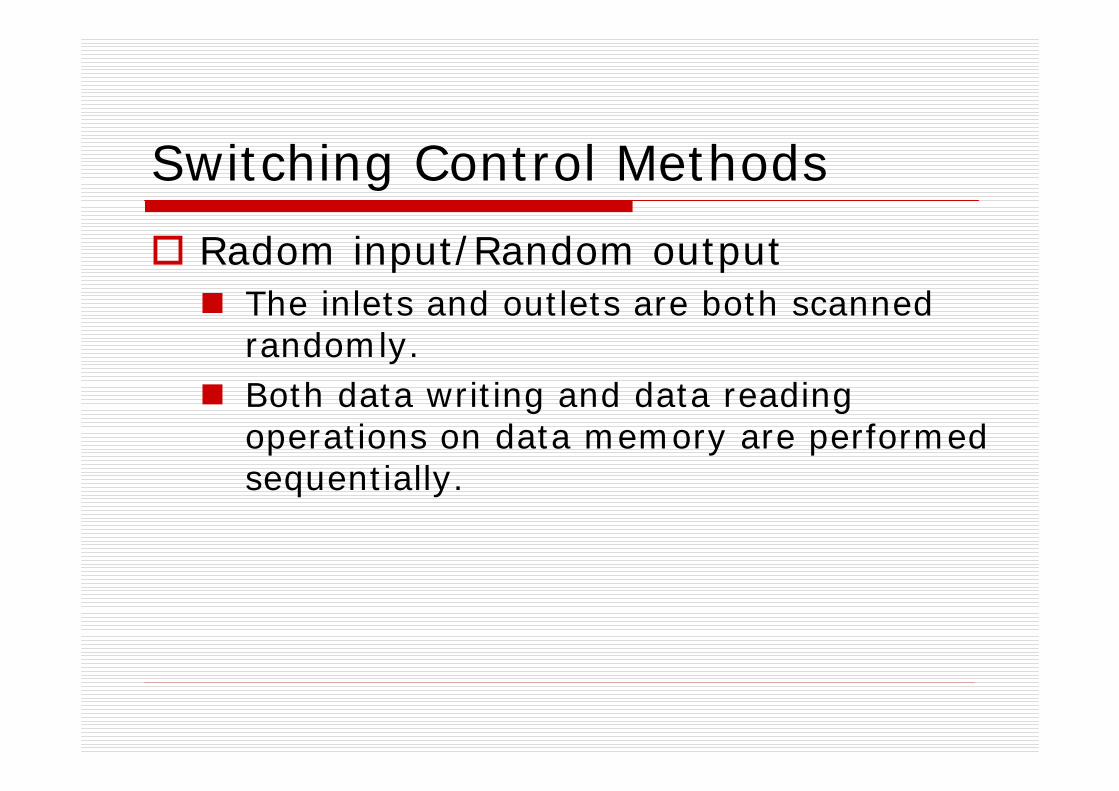
Radom input/Random outputThe inlets and outlets are both scanned randomly.Both data writing and data reading operations on data memory are performed sequentially.
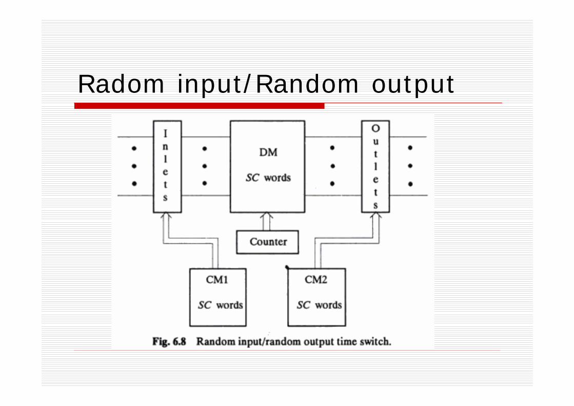
Radom input/Random output
Operation modes
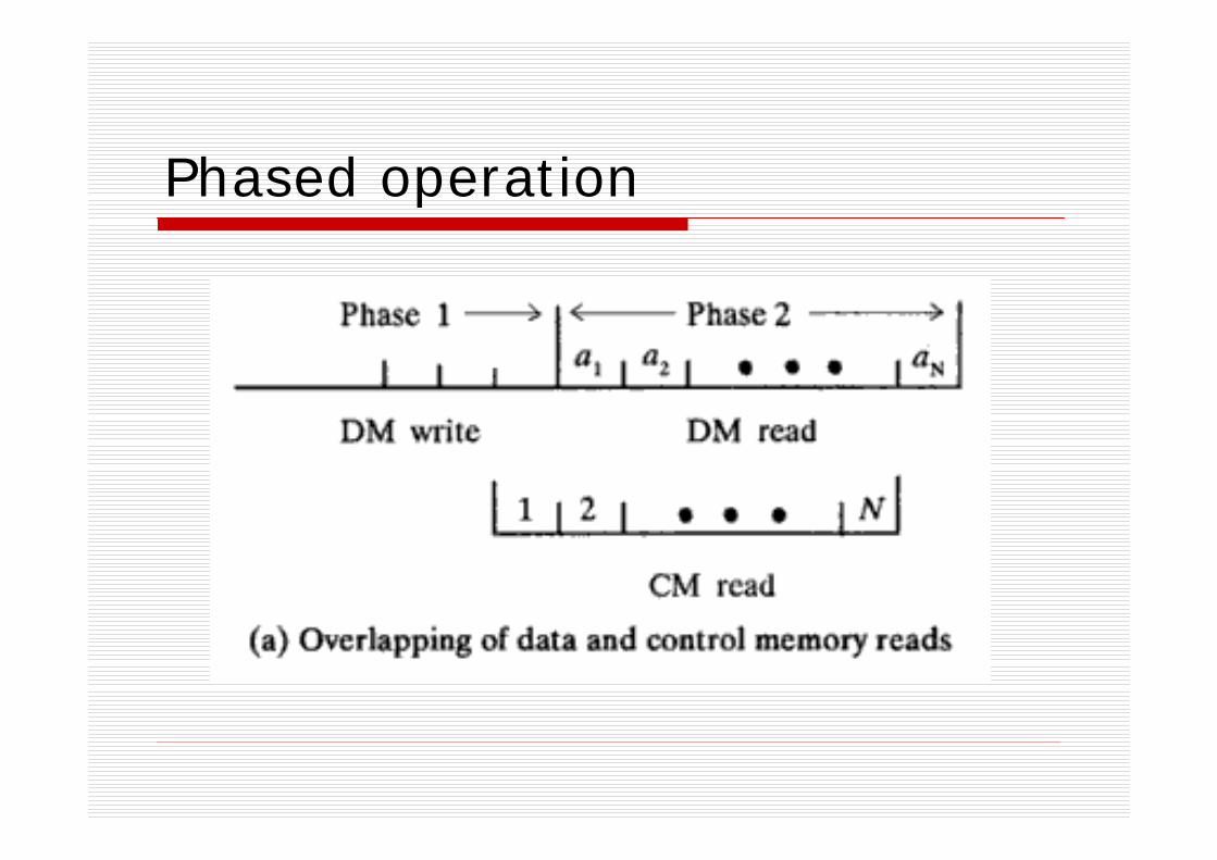
Phased operation 阶段化操作模式
Slotted operation 时隙化操作模式
Operation modes
Phased operation 阶段化操作模式The switching procedure is divided into two phases.Phase1: The data from inlets are stored in the data memory sequentially or randomly according to control method used.Phase2: The data are read from data memory and delivered to outlets sequentially or randomly according to the control method used.
Phased operation
Operation modes
Slotted operation 时隙化操作模式
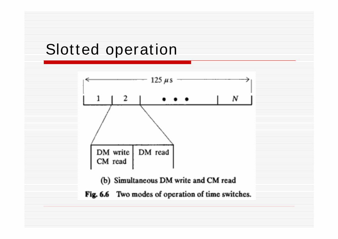
The operation period (125us) is divided into slots according to switching capacity.In each time slot, the data from a inlet is stored in data memory, and then a data is read and delivered to its corresponding outlet.One sample delay (125us) may be introduced.
Slotted operation
RemarksBoth sequential write/random read and random write/sequential read control modes are nonblocking in nature, but the number of subscribers can be connected to the system is no more than the switching capacity SC.Random input/Random output control mode permits a large number of subscribersconnected to the system, but it is blockingin nature.Each of the inlets/outlets corresponds to a single subscriber. Suitable for local exchanges.
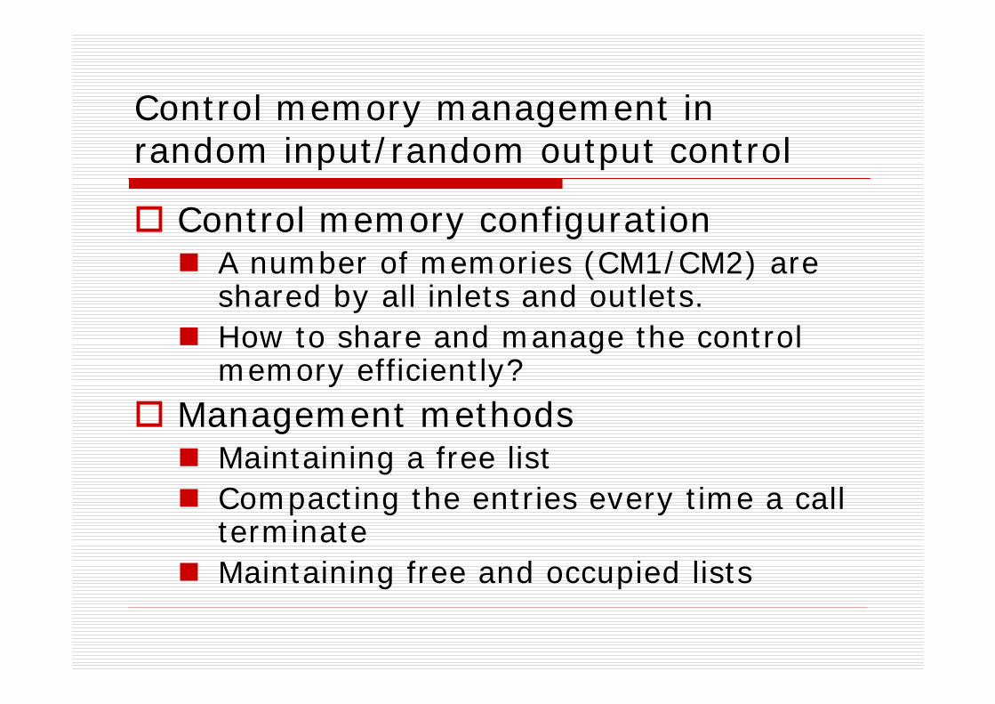
Control memory management in random input/random output control
Control memory configurationA number of memories (CM1/CM2) are shared by all inlets and outlets.How to share and manage the control memory efficiently?
Management methodsMaintaining a free listCompacting the entries every time a call terminateMaintaining free and occupied lists

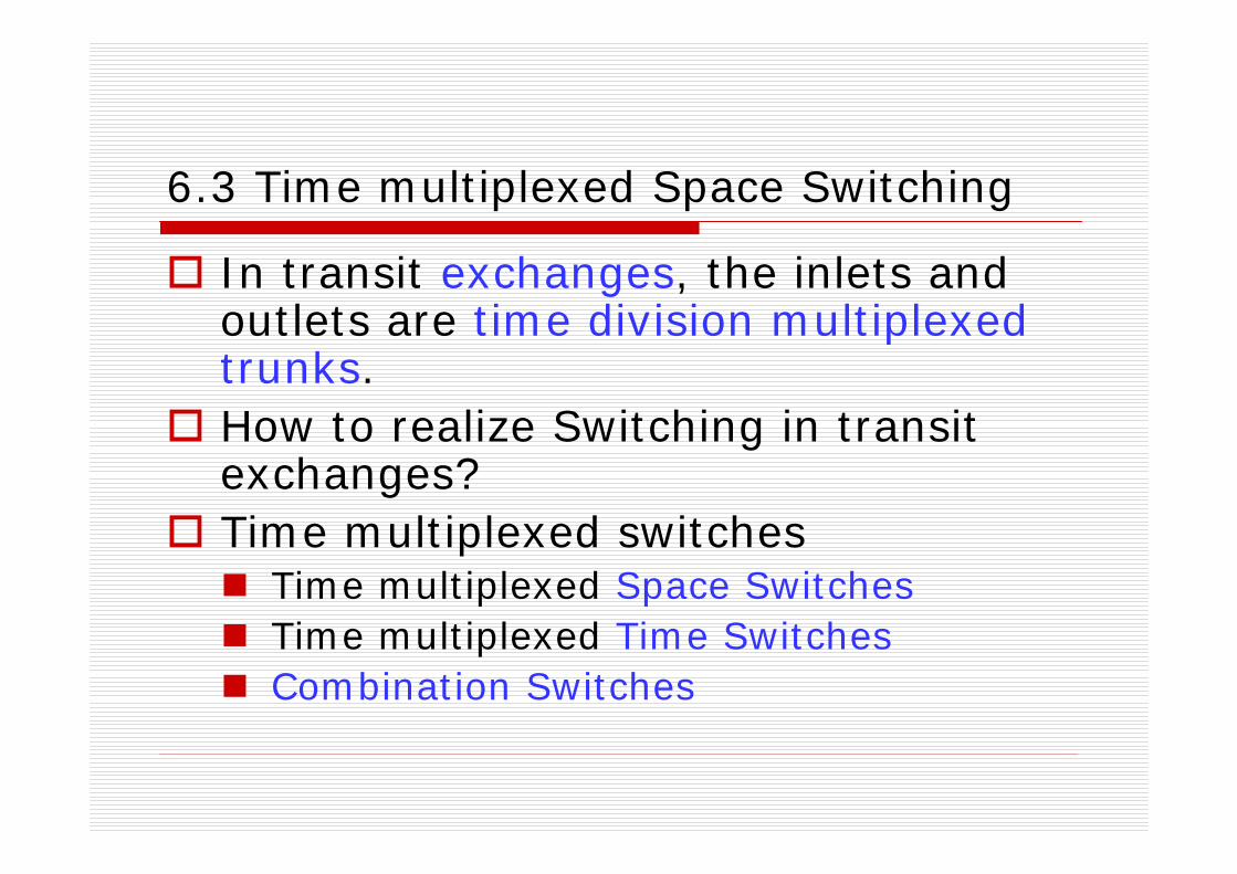
6.3 Time multiplexed Space Switching
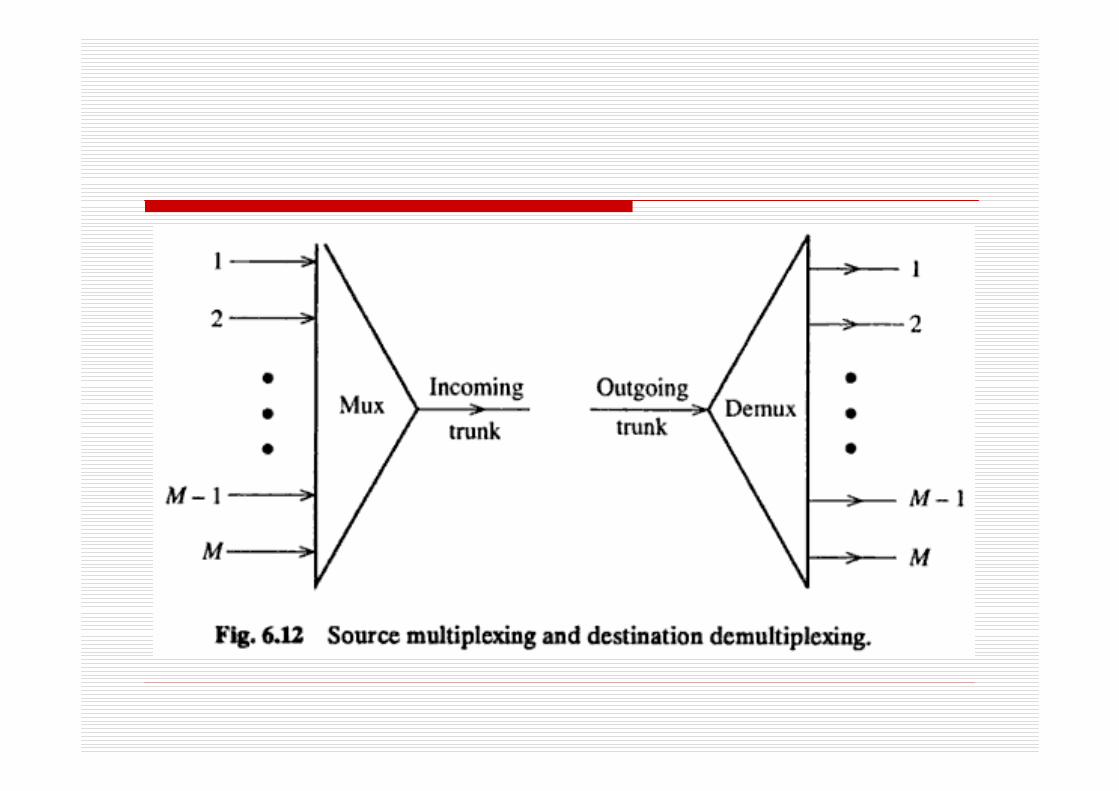
In transit exchanges, the inlets and outlets are time division multiplexed trunks. How to realize Switching in transit exchanges?Time multiplexed switches
Time multiplexed Space SwitchesTime multiplexed Time SwitchesCombination Switches

Time multiplexed switching
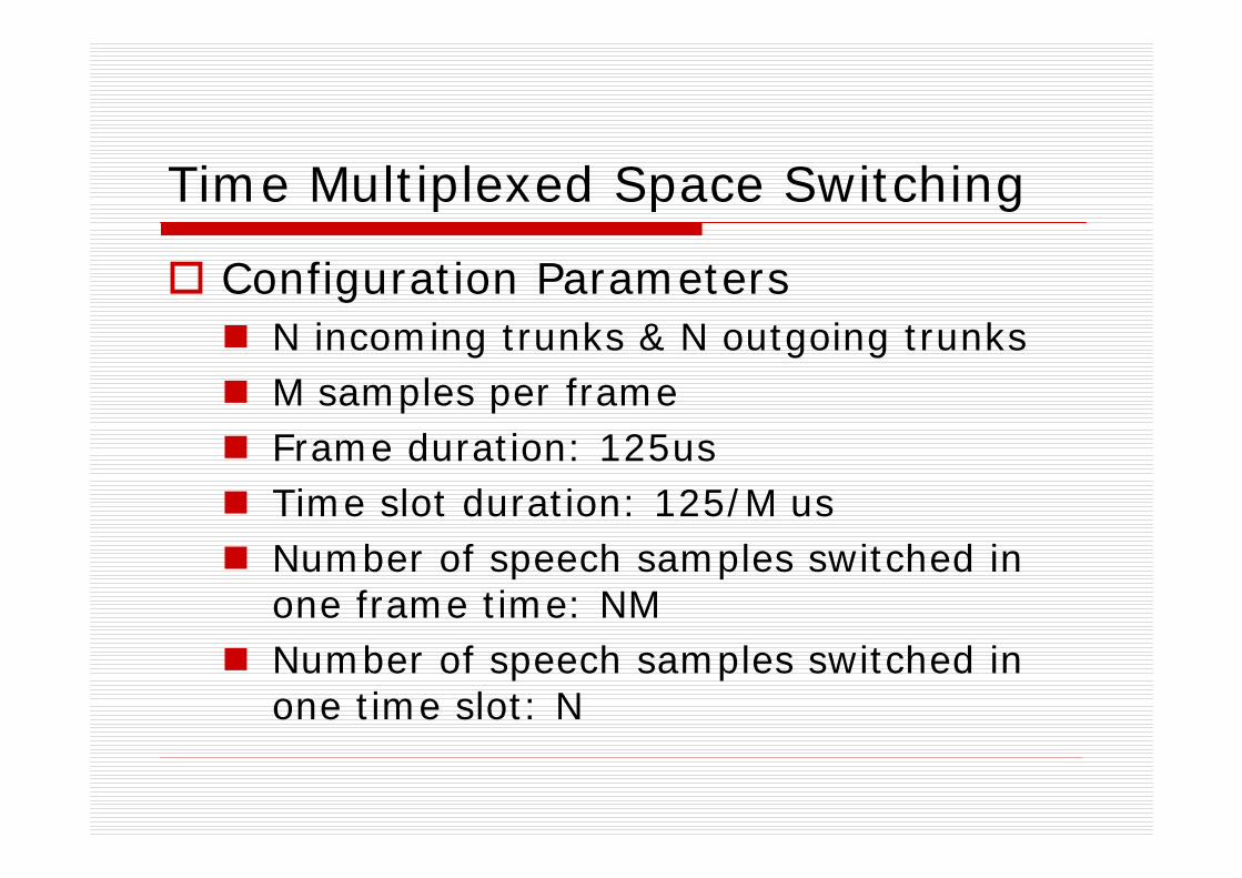
Time Multiplexed Space Switching
Configuration ParametersN incoming trunks & N outgoing trunksM samples per frameFrame duration: 125usTime slot duration: 125/M usNumber of speech samples switched in one frame time: NMNumber of speech samples switched in one time slot: N
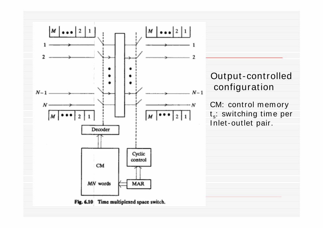
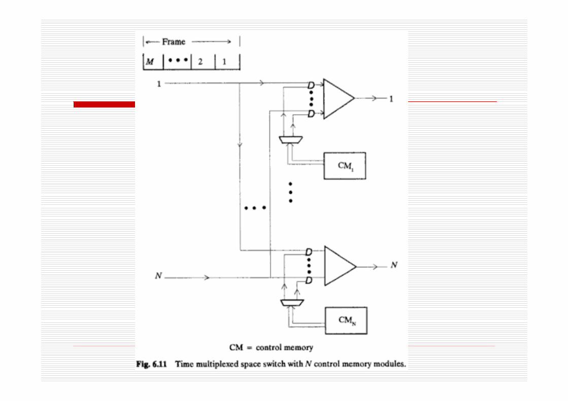
Output-controlledconfiguration
CM: control memoryts: switching time perInlet-outlet pair.
Time Multiplexed Space Switching
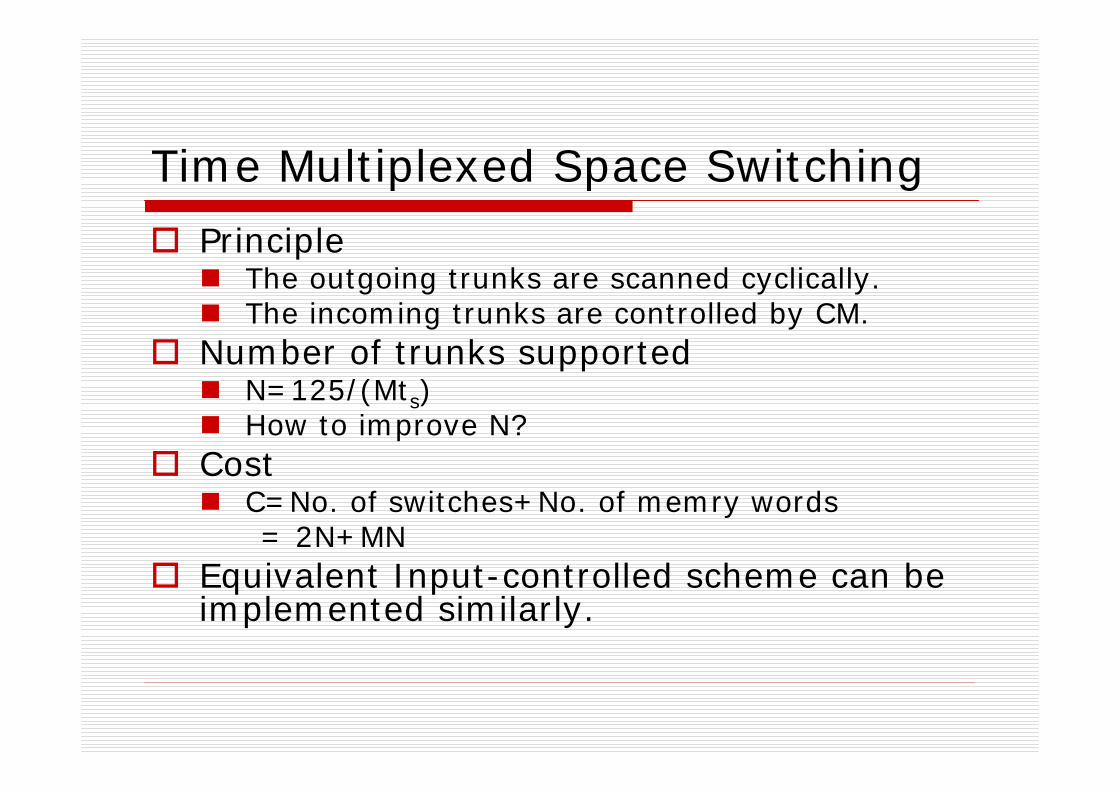
PrincipleThe outgoing trunks are scanned cyclically.The incoming trunks are controlled by CM.
Number of trunks supportedN=125/(Mts)How to improve N?
CostC=No. of switches+No. of memry words= 2N+MN
Equivalent Input-controlled scheme can be implemented similarly.
A modified scheme
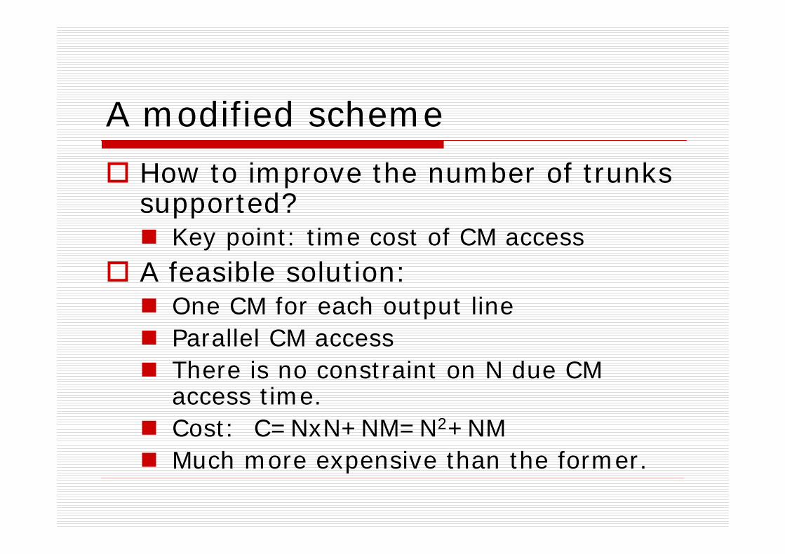
How to improve the number of trunks supported?
Key point: time cost of CM accessA feasible solution:
One CM for each output lineParallel CM accessThere is no constraint on N due CM access time.Cost: C=NxN+NM=N2+NMMuch more expensive than the former.
Remarks
Word width: log2NFull availability: no
Subscribers belonging to different time slots can not be connected.
Broadcast: yes
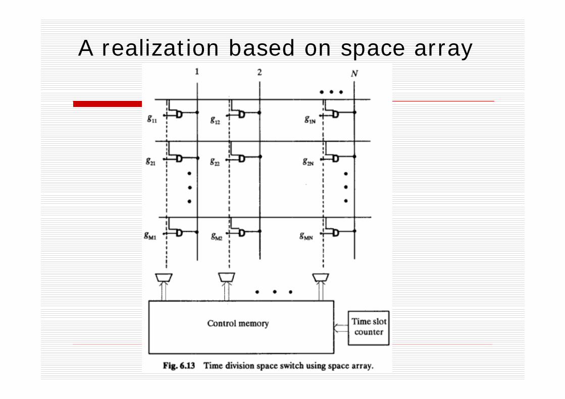
A realization based on space array
6.4 Time multiplexed time switching
How to realize switching among subscribers belonging to different time slots?
Memory write/read based methodPrinciple of time slot interchange (TSI)
Category:Random write/Sequential readSequential write/Random read
Sample time delays
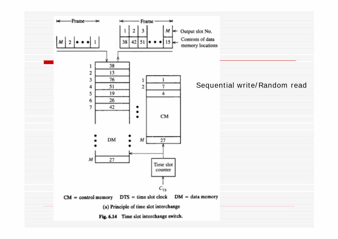
Sequential write/Random read
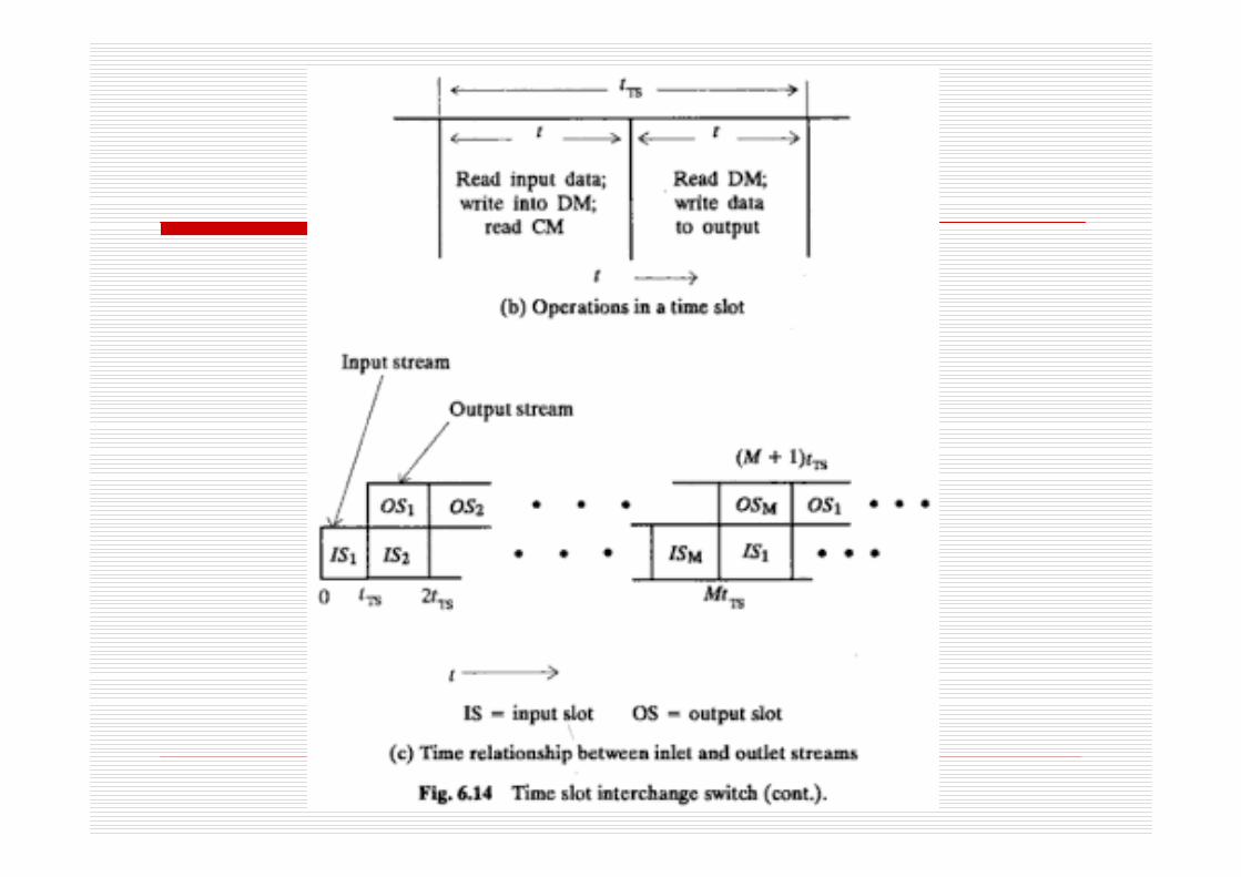
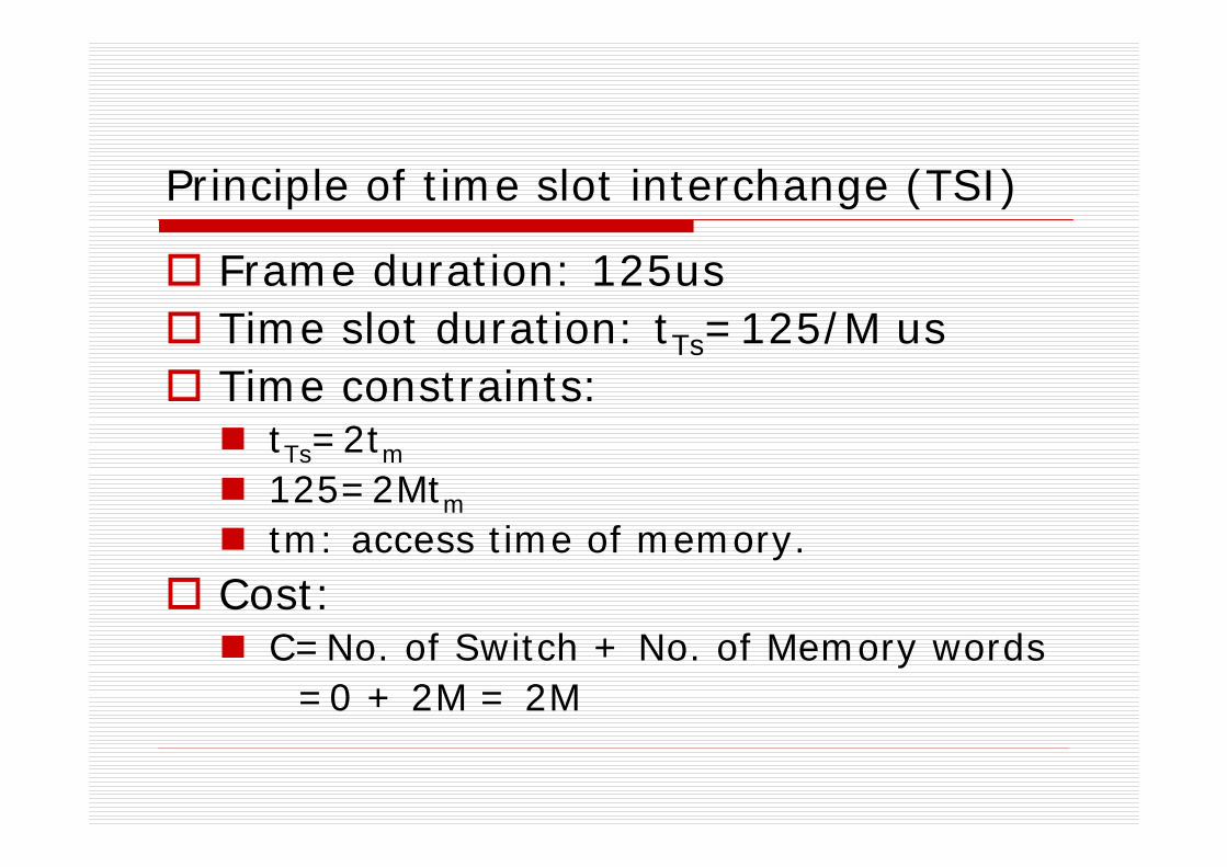
Principle of time slot interchange (TSI)
Frame duration: 125usTime slot duration: tTs=125/M usTime constraints:
tTs=2tm
125=2Mtm
tm: access time of memory.Cost:
C=No. of Switch + No. of Memory words =0 + 2M = 2M
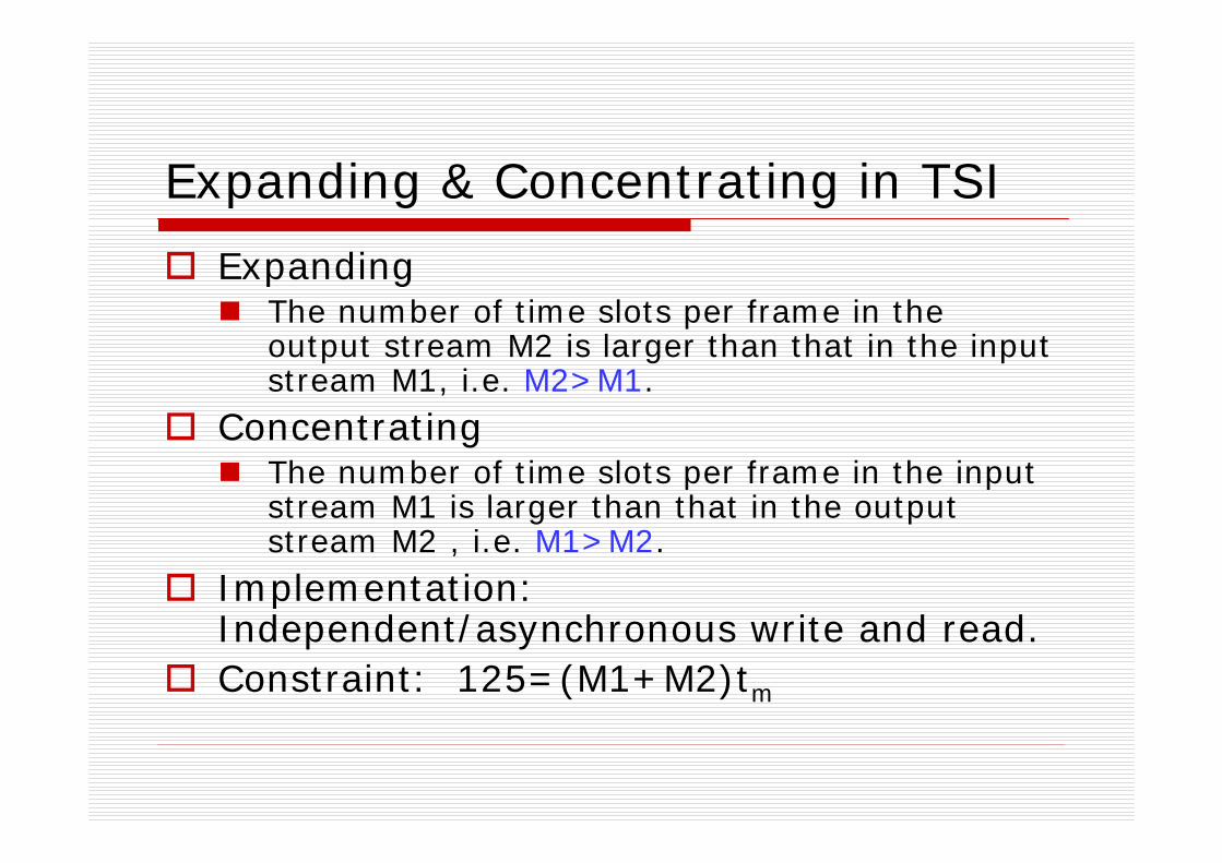
Expanding & Concentrating in TSI
ExpandingThe number of time slots per frame in the output stream M2 is larger than that in the input stream M1, i.e. M2>M1.
ConcentratingThe number of time slots per frame in the input stream M1 is larger than that in the output stream M2 , i.e. M1>M2.
Implementation: Independent/asynchronous write and read.Constraint: 125=(M1+M2)tm
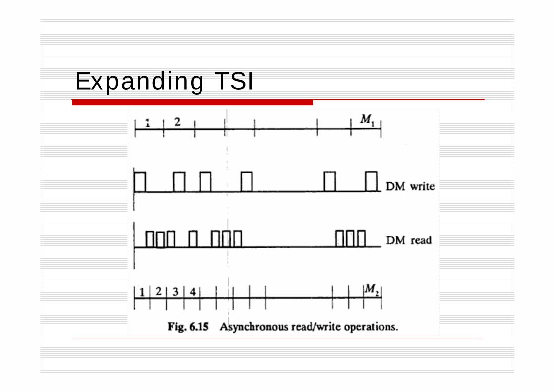
Expanding TSI
Time multiplexed time switching
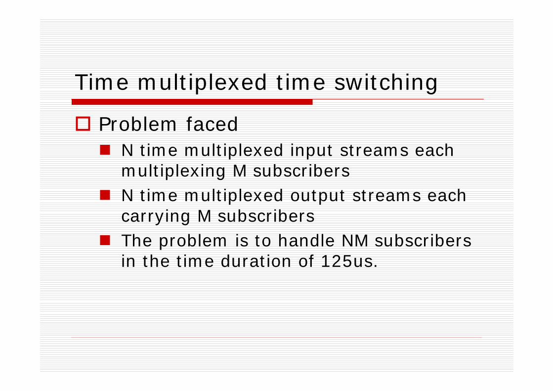
Problem facedN time multiplexed input streams each multiplexing M subscribersN time multiplexed output streams each carrying M subscribersThe problem is to handle NM subscribers in the time duration of 125us.
Time multiplexed time switching
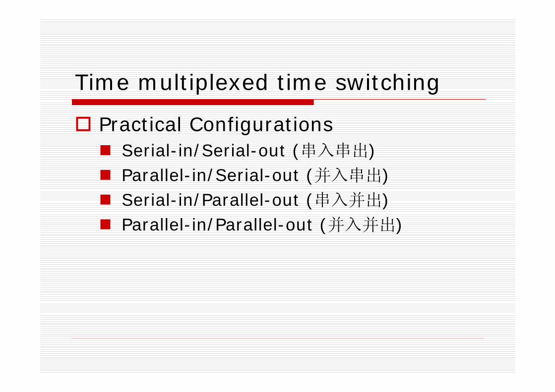
Practical ConfigurationsSerial-in/Serial-out (串入串出)Parallel-in/Serial-out (并入串出)Serial-in/Parallel-out (串入并出)Parallel-in/Parallel-out (并入并出)
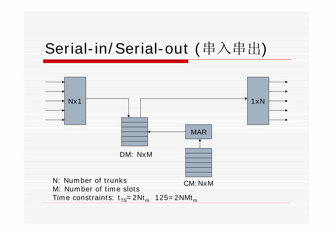
Serial-in/Serial-out (串入串出)
Nx1 1xN
MAR
DM: NxM
CM:NxMN: Number of trunksM: Number of time slotsTime constraints: tTS=2Ntm 125=2NMtm

Serial-in/Serial-out (串入串出)
DM write DM readCM read DM write DM read
CM read DM write DM readCM read
1 2 N
tTS=2Ntm
TS1 TS2 TS3 TS4 TSM-1 TSM
125=MtTS=2NMtm
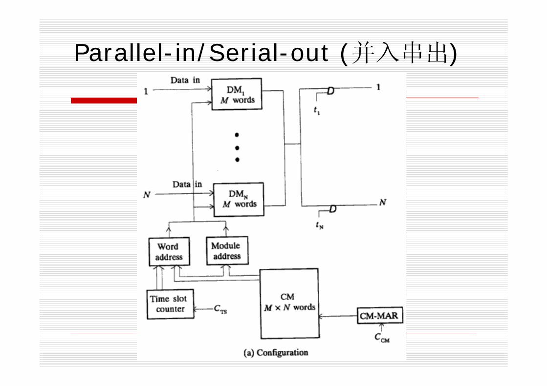
Parallel-in/Serial-out (并入串出)
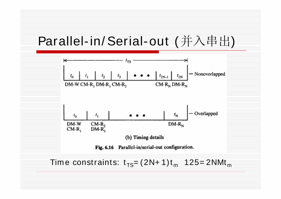
Parallel-in/Serial-out (并入串出)
Time constraints: tTS=(2N+1)tm 125=2NMtm
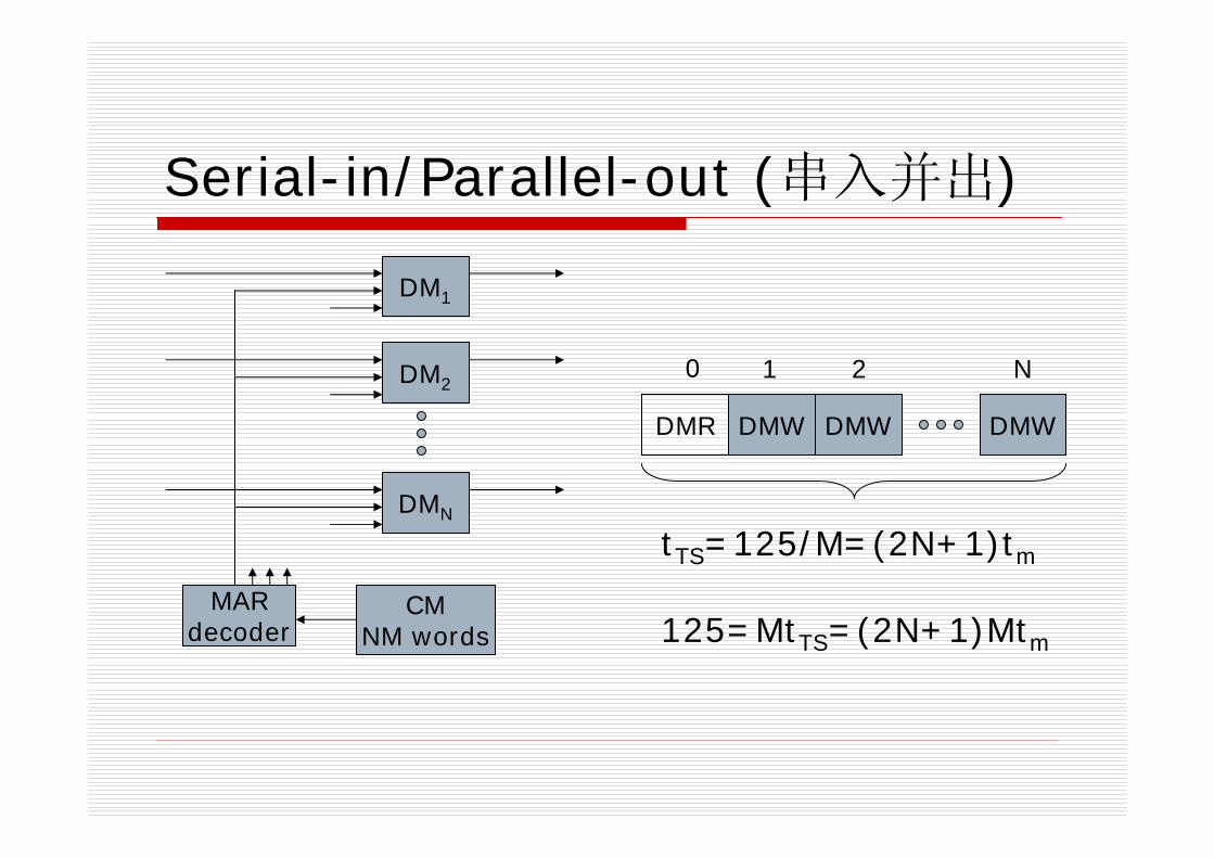
Serial-in/Parallel-out (串入并出)
DM1
DM2
DMN
CMNM words
MARdecoder
DMR DMW DMW DMW
0 1 2 N
tTS=125/M=(2N+1)tm
125=MtTS=(2N+1)Mtm
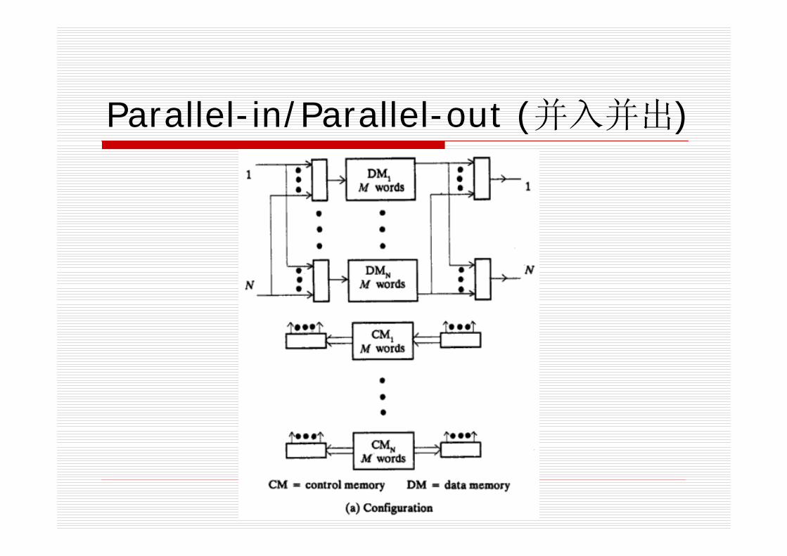
Parallel-in/Parallel-out (并入并出)
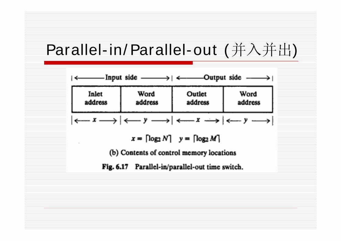
Parallel-in/Parallel-out (并入并出)

Remarks
Time multiplexed time switches do not provide full availability, because they are not capable of switching samples across trunks.
6.5 Combination Switching
How to provide full availability for time multiplexed trunks?
Both space switching and time slot switching should be performed.
Combination SwitchingBasic idea: Multistage & Space + TimeCategory
Two-stageThree-stagemultistage
Two-stage combination switches
Configurations of two-stage ~Time-space (TS) switch
The first stage performs time switching;The second stage performs space switching.
Space-time (ST) switchThe first stage performs space switching;The second stage performs time switching.
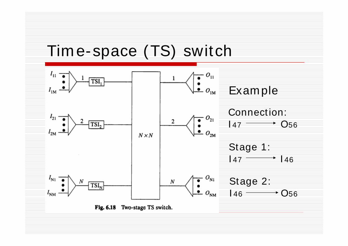
Time-space (TS) switch
Connection:I47 O56
Stage 1:I47 I46
Stage 2:I46 O56
Example
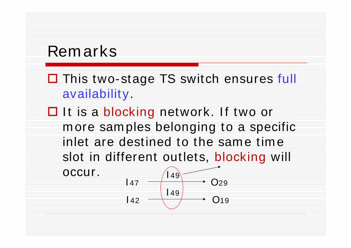
Remarks
This two-stage TS switch ensures full availability.It is a blocking network. If two or more samples belonging to a specific inlet are destined to the same time slot in different outlets, blocking will occur.
I47
I42
O29
O19
I49
I49
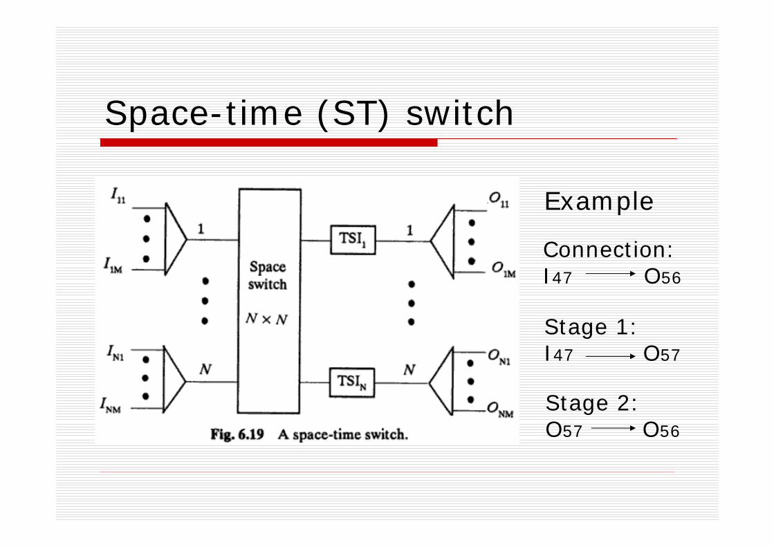
Space-time (ST) switch
Connection:I47 O56
Stage 1:I47 O57
Stage 2:O57 O56
Example

Remarks
This two-stage ST switch ensures full availability.It is a blocking network. If two or more samples originating from different inlets during the same time slot are destined to the same outlet, blocking will occur.
I60
I40
O29
O25
O20
O20
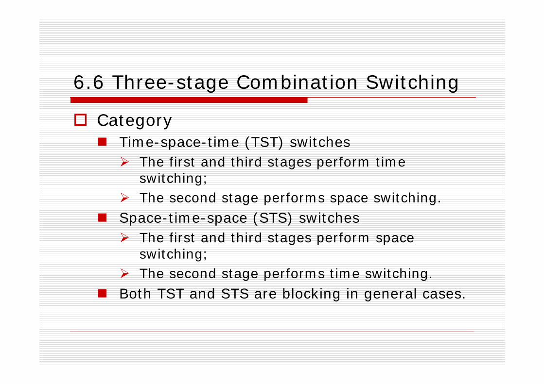
6.6 Three-stage Combination Switching
CategoryTime-space-time (TST) switches
The first and third stages perform time switching;The second stage performs space switching.
Space-time-space (STS) switchesThe first and third stages perform space switching;The second stage performs time switching.
Both TST and STS are blocking in general cases.
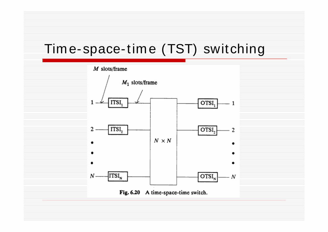
Time-space-time (TST) switching
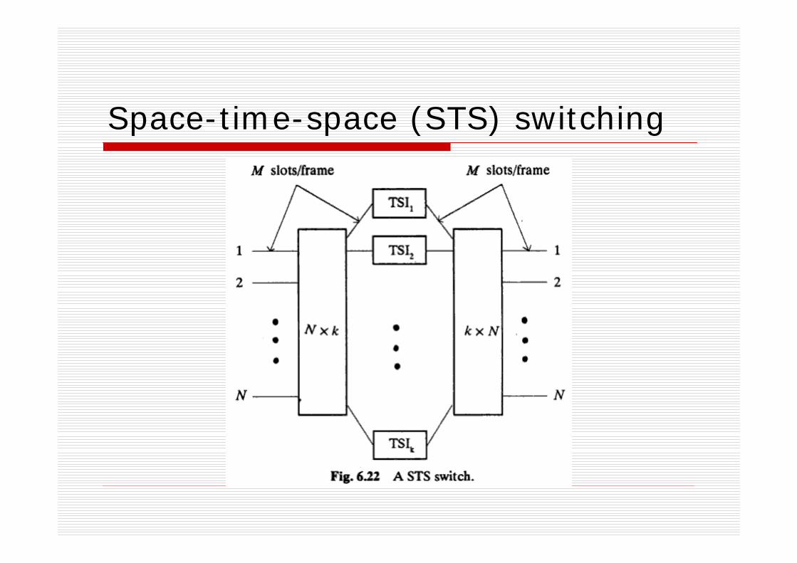
Space-time-space (STS) switching

Costs of TST and STS
TSTCTST=5MN+N2
STSCSTS=2Nk+4MN
The blocking probability is reduced by providing more feasible paths for any inlet-outlet pair.
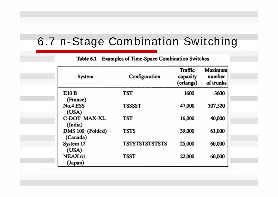
6.7 n-Stage Combination Switching
Assignments
Ex.2Ex.6


![Cisco AS5400XM Universal Gatewaydoretel.com/documents/CiscoAS5400XMVoIPGatewayDataSheet.pdf[VoIP] and 2 CT3 of time-division multiplexing [TDM] switching), low power consumption (as](https://static.fdocuments.in/doc/165x107/60cfff6d4b24ac5c8a189ba8/cisco-as5400xm-universal-voip-and-2-ct3-of-time-division-multiplexing-tdm-switching.jpg)