CHAPTER 6 SURFACE TEMPERATURE...
45
66 CHAPTER 6 SURFACE TEMPERATURE PREDICTION 6.1 LOW HEAT REJECTION ENGINES - AN OVERVIEW Energy conservation and efficiency have always been the quest of engineers concerned with internal combustion engines. The diesel engine generally offers better fuel economy than its counterpart petrol engine. Even the diesel engine rejects about two thirds of the heat energy of the fuel, one- third to the coolant, and one third to the exhaust, leaving only about one-third as useful power output. Theoretically if the heat rejected could be reduced, then the thermal efficiency would be improved, at least up to the limit set by the second law of thermodynamics. If combustion gas energy can be contained through the expansion cycle, then the efficiency of the engines can be increased. To increase the efficiency of IC engines and generate higher combustion chamber temperatures, low heat rejection concept is investigated. Low Heat Rejection engines aim to do this by reducing the heat lost to the coolant. The diesel engine with its combustion chamber walls insulated by ceramics is referred to as Low Heat-Rejection (LHR) engine. The LHR engine has been conceived basically to improve fuel economy by eliminating the conventional cooling system and converting part of the increased exhaust energy into shaft work using the turbocharged system. Adiabatic engine implies a no heat loss engine, as adiabatic process is defined as a no-heat loss process since the combustion chamber walls have no thermal capacity or inertia. But, under such imaginary cases, there would be no heat flow relative
Transcript of CHAPTER 6 SURFACE TEMPERATURE...
66
CHAPTER 6
SURFACE TEMPERATURE PREDICTION
6.1 LOW HEAT REJECTION ENGINES - AN OVERVIEW
Energy conservation and efficiency have always been the quest of
engineers concerned with internal combustion engines. The diesel engine
generally offers better fuel economy than its counterpart petrol engine. Even
the diesel engine rejects about two thirds of the heat energy of the fuel, one-
third to the coolant, and one third to the exhaust, leaving only about one-third
as useful power output. Theoretically if the heat rejected could be reduced,
then the thermal efficiency would be improved, at least up to the limit set by
the second law of thermodynamics. If combustion gas energy can be
contained through the expansion cycle, then the efficiency of the engines can
be increased. To increase the efficiency of IC engines and generate higher
combustion chamber temperatures, low heat rejection concept is investigated.
Low Heat Rejection engines aim to do this by reducing the heat lost to the
coolant.
The diesel engine with its combustion chamber walls insulated by
ceramics is referred to as Low Heat-Rejection (LHR) engine. The LHR
engine has been conceived basically to improve fuel economy by eliminating
the conventional cooling system and converting part of the increased exhaust
energy into shaft work using the turbocharged system. Adiabatic engine
implies a no heat loss engine, as adiabatic process is defined as a no-heat loss
process since the combustion chamber walls have no thermal capacity or
inertia. But, under such imaginary cases, there would be no heat flow relative

67
to the cylinder walls. The ways and means of realization of such a combustion
chamber are not realistic in practice. However the insulated combustion
chamber either partially or fully can be assumed to have a large thermal
capacity or inertia. The surfaces of the combustion chamber remain at a
constant temperature throughout the operation. Such an engine is called a
Low Heat Rejection (LHR) engine. In the development of LHR engine, the
reduction of heat loss to the coolant system has always been of considerable
interest to engine designers because, this would reduce the cost, weight,
power requirement and size of the cooling system. In gasoline engines, the
thermal insulation will increase the wall temperature which will lead to
unwanted detonation. Because of this, insulation of the combustion chambers
could be done only to diesel engines. This has two important purposes-to
reduce the size of coolant system & to increase the exhaust energy available
for turbo charging and thereby increasing power and efficiency.
In the insulated engines, the wall temperatures increase. Hence in a
natural aspirated engine the intake air gets heated and reduces the volumetric
efficiency. To maintain the volumetric efficiency, the insulated engines are
usually turbo charged. This maintains the volumetric efficiency and hence the
power output. The excess energy in the exhaust is used to drive turbines and
the combination gives the highest efficiency.
In LHR engine the combustion chamber is insulated with high
temperature materials which makes the engine operate at hotter environment
with less heat transfer. The components that are normally insulated include
piston, cylinder head, valves, cylinder liner, and exhaust ports. It is expected
that additional power and improved efficiency is possible with engine
insulated because thermal energy that is normally lost to the cooling water
and exhaust gas is converted to useful power through the use of turbo
machinery and high temperature materials. Insulation of the combustion
68
chamber is done by coating it with ceramics. Partially stabilized zirconia and
aluminium titanate are used for coating. The coating is mainly done by
plasma spraying. The spraying parameters are very important in determining
the reliability of the coating. A 0.5mm layer of zirconia will reduce the heat
rejection to the coolant by 48%, while a 1mm layer is required to reduce the
heat flow by 78%. The engine components which are commonly coated are
cylinder head, valves, liners and piston crown.
According to the first law of thermodynamics, and energy which is
not rejected the coolant remains available to produce useful piston work.
According to second law of thermodynamics, combustion taking place at
higher temperature is also more efficient as irreversibility decrease with
increasing temperature. The reduction in heat losses also results in increased
exhaust enthalpy. This extra exhaust energy can be utilized to drive a
compounding turbine or a bottoming cycle, thus improving the overall
efficiency. From the above, it is expected that the insulated diesel engine
should easily outperform the standard cooled engine. However, experiments
reveal that in many cases, the performance of LHR engine is only slightly
better, in a few cases worse than the cooled version of the same engine.
A more likely cause for the performance changes is that the introduction of
insulation in the cylinder could significantly alter the combustion process.
In a LHR engine, shorter ignition delays are expected, thus leading
to a decreased premixed fraction and a corresponding increase in the amount
of fuel burned during the diffusion phase of combustion. With the heat
release shifted later in the cycle, less useful work would be extracted from the
insulated engine. In other words, in order to realize the benefits of the LHR
engine, the combustion system has to be modified to maintain a desirable heat
release profile. The changes in the combustion process due to insulation also
affect exhaust emissions. Higher gas temperatures are supposed to reduce the
69
concentration of incomplete combustion at the expense of increase in nitric
oxide.
The combustion chamber wall temperature of an LHR engine is
higher than that of a conventional water-cooled engine. Hence the charged air
in a cylinder absorbs heat emanating from the high temperature chamber wall.
Therefore the charged air expands, this lessening the amount of intake air.
However if the increase in power output is to be realized, a turbocharger using
higher exhaust energy and which increase the amount of intake air, or better
still, a turbo compound system that recovers that exhaust energy and converts
it into additional power should be connected with the LHR diesel engines.
The excess air ratio also decreases by about 1 to 7.6% compared to that of
water cooled, turbocharged base engine. Cooling the liner with water even in
the case of a naturally aspirated insulated engine can moderate the
deterioration in volumetric efficiency. The rate of heat release in the diffusion
combustion phase shows a decreasing trend from the early to middle period
and lengthening of the subsequent after-burning period.
6.2 EFFECT OF COATING ON ENGINE PERFORMANCE
PARAMETERS
6.2.1 Volumetric Efficiency
Volumetric efficiency is an indication of breathing ability of the
engine. It depends on the ambient conditions and operating conditions of the
engine. Reducing heat rejection with the addition of ceramic insulation causes
an increase in the temperature of the combustion chamber walls of an LHR
engine. The volumetric efficiency thus drops, as the hotter walls and residual
gas decrease the density of the inducted air. The deterioration in volumetric
efficiency of the LHR engine can be prevented by turbo charging, and that
there can be more effective utilization of the exhaust gas energy.

70
6.2.2 Thermal Efficiency
Thermal efficiency is the true indication of the efficiency with
which the chemical energy input in the form of fuel is converted into useful
work. Improvement in engine thermal efficiency by reduction of in-cylinder
heat transfer is the key objective of LHR engine research. Much work has
been done at many research institutes to examine the potential of LHR
engines for reducing heat rejection and achieving high thermal efficiency.
Researches indicate improvement in thermal efficiency with LHR engine.
They attribute this to in cylinder heat transfer reduction and lower heat flux.
However investigations of others report that thermal efficiency reduces with
insulation. They all attribute this to an increase in the convective heat transfer
coefficient, higher heat flux (increase in in-cylinder heat transfer) and
deteriorated combustion. The in-cylinder heat transfer characteristics of LHR
engine are still not clearly understood. Thus the effect of combustion chamber
insulation on reducing heat rejection and hence on thermal efficiency is not
clearly understood as on date.
6.2.3 Specific Fuel Consumption
Numerous investigators have modeled and analyzed the effects of
in-cylinder thermal insulation on fuel consumption and have reported
improvement in the reduction of fuel consumption in LHR engine. The level
of improvement that has been predicted ranged from 2 to 12 %. They attribute
this to insulation of in-cylinder components. It has been predicted that
insulation of in-cylinder components is a more effective means of reducing
heat rejection and reducing fuel consumption. Some attribute this to reduced
friction due to increased wall temperature. Some investigations indicate
higher fuel consumption of LHR engine which is attributed to the increase in
reciprocating mass. In general, it has been reported that fuel consumption of,
71
naturally aspirated LHR engine is in the range of 0 to 10% higher,
turbocharged LHR engine in the order of 0 to 10% lower and turbo
compounded LHR engine in the order of 0 to 15% lower, when compared
with the conventional cooled engine.
6.2.4 Injection Characteristics
In heavy-duty diesel engines, rather than air motion, the momentum
and energy of the injected fuel are the major physical factors, which control
the air fuel mixing process. Accordingly it is necessary to optimize the fuel
injection system of the heavy-duty un-cooled LHR diesel engines. The
investigations show that the fuel economy of the LHR engine is of the same
level as that of water cooled engine at the medium load, but deteriorated
significantly at the high load condition which is attributed to increased
temperature of the combustion chamber walls, thus also increasing the
temperature of the fuel issuing from the heated nozzle orifice resulting in the
reduced fuel viscosity which causes a heavy leakage fuel inside the nozzle
and extended injection duration as well. Some experimental data show that
higher insulated temperature in the insulated engine alters both the needle lift
and line pressure. It has been shown that with proper adjustment of the
injection timing it is possible to partially offset the adverse effect of insulation
on heat release rate. The data shows that reducing heat rejection from the
cylinder, shift the combustion from pre-mixed towards diffusion and by
advancing the timing; the LHR engine achieves the same pre-mixed heat
release rate. Injection pressure and rate can also offset the adverse effect of
insulation.
72
6.3 EFFECT OF COATING ON ENGINE EMISSION
PARAMETERS AND NOISE
6.3.1 Unburned Hydrocarbon
The emission of unburned Hydrocarbon from the LHR engines is
more likely to be reduced because of the decreased quenching distance and
the increased lean flammability limit. The higher temperatures both in the
gases and at the combustion chamber walls of the LHR engine assist in
permitting the oxidation reactions to proceed close to completion. However
some investigations indicate increased level of HC emissions which is
attributed to deterioration in diffusion combustion. The burning of lubricating
oil due to high wall temperature is believed to be the other reason for
increased UBHC level.
6.3.2 Carbon Monoxide
LHR engines produce less carbon monoxides, for reasons similar to
those for unburned Hydrocarbon which is attributed to high gas temperature
and combustion chamber walls. The reduced level of pre-mixed combustion
in the insulated engine decreases the initial production of CO and the higher
temperatures during diffusion combustion accelerate the oxidation of CO.
6.3.3 Oxides of Nitrogen
NOx is formed by chain reactions involving Nitrogen and Oxygen
in the air. These reactions are highly temperature dependent. Since diesel
engines always operate with excess air, NOx emissions are mainly a function
of gas temperature and residence time. NOx emission from LHR engines is
generally higher than that in water-cooled engines due to higher combustion
temperature and longer combustion duration. Many investigations report an
increase in the LHR engine NOx emissions and concluded that diffusion

73
burning is the controlling factor for the production of NOx while other
investigations indicate reduction in NOx level due to the shortening of the
ignition delay that decreases the proportion of the premixed combustion.
6.3.4 Smoke and Particulates
It is expected that LHR engines would produce less smoke and
particulates than standard engines for reasons such as high temperature gas
and high temperature combustion chamber wall. Also enhanced soot
oxidation, which was made possible by both the high combustion temperature
and the intense turbulence created by the reversed squish reduces smoke.
Factors such as short ignition delay, poor air-fuel mixing are also responsible
for the formation of smoke and particulates.
6.3.5 Noise
Ceramics are light weight materials when compared with the
common metals and alloys, because they are less dense in nature. So it is
generally expected that use of such material for engine components would
decrease the noise generated in an engine. The rotating and the reciprocating
masses can be lighter, decreasing response time, noise and the required spring
forces for successful operation. Lighter materials will decrease vibration
created in the system. Friction would also be decreased as would the resultant
friction or sustaining work required and decrease the noise at that interaction.
6.4 USE OF CERAMIC MATERIAL IN IC ENGINES-AN
APPROACH
The choice of metal as the material from which heat engines are
made is an unfortunate one. This is because metals are relatively low
temperature materials for heat engines and they are also good thermal
74
conductors, two properties that are detrimental to efficient combustion.
Historically, when the internal combustion engine was first
being developed, it was an unavoidable choice because metals were the only
suitable material available at that time. Development of new materials for IC
engines is now being encouraged worldwide.
The maximum service temperature of many metals is less than
6000C, and thus metal engines are required to operate at temperatures too low
for fuel to be burnt completely. Also, as metals are good thermal conductors,
the heat generated within the metallic combustion chamber is asily conducted
through the metallic casing. Liquid cooling is thus required to prevent the
metallic engine from overheating and this hastens heat loss (about 30% of the
heat generated is lost to the coolant or radiator water). Furthermore, resulting
incomplete combustion products are discarded through the exhaust adding to
airborne pollution. This temperature trade-offs required of metallic internal
combustion engines result in low combustion and low thermal efficiencies.
Thus, metallic internal combustion engines suffer primarily from three
problems namely Low combustion efficiency (due to the lower operating
temperatures of metals), Substantial heat loss (due to the high thermal
conductivity of metals), and Wear (resulting in some limited metal component
life).
As ceramics are high temperature materials, a ceramic engine
should be able to operate at higher temperatures enabling combustion of
fuel to be more complete resulting in increased combustion efficiency. This
should increase performance, decrease fuel consumption and reduce pollution.
This should also enable various fuels to be used. A suitable engine material
should have twin capabilities; namely be able to operate at high temperatures
and also contain the heat generated within the combustion chamber. Ceramic
75
is such a material. It is a high temperature material and it also possesses a low
thermal conductivity.
The following are the advantages of using ceramics in IC engines -
(1) Ability to operate at higher temperatures resulting in more
complete combustion of fuel and increased thermal and
combustion efficiency (and could lead to decreased fuel
consumption)
(2) They are relatively good thermal insulators and are thus able
to reduce the heat lost to the surroundings (e.g. the thermal
conductivity of zirconia ceramics is about 2 W/m.K).
(3) It reduces the heat rejected from the working chamber of an
internal combustion engine to the engine's cooling system and
thus improves engine efficiency.
(4) It eliminates the need for continuous lubrication of the
engine's cylinder walls.
(5) It eliminates the need to consider the wear resistance of the
thermal barrier material to be used, thus providing a greater
selection thereof.
Therefore making the combustion chamber of an internal
combustion engine entirely out of a ceramic or else insulating the surface of
the combustion chamber with ceramic tiles should improve the engine's
combustion characteristics and reduce heat loss. This could lead to higher
engine performance and lower exhaust emissions.
76
6.5 VARIOUS CERAMIC MATERIALS USED IN IC ENGINES
The following ceramics have long been used for coating on the
combustion chamber of IC engines.
6.5.1 Silicon Nitride
Among the various engineering ceramics that have been developed
over the decades, silicon nitride has received the most attention for use in
internal combustion engines and turbines. It has good thermal
shock resistance (ΔT ~ 6000C) and good creep resistance. Though very
desirable as an engine material, their poor mechanical strength (low fracture
toughness) has precluded their use in load-bearing applications. As the
brittleness of silicon-based ceramics is considered an intrinsic characteristic
of such materials by virtue of their strong bonding, covalent and ionic,
only limited increases in the fracture toughness of silicon nitride is believed to
be attainable. The development of ceramic matrix composites (CMC) is
considered to be a more attractive alternative, but success in this approach has
been limited. Although some progress has been made over the years, the
processing of silicon nitride remains a problem and larger higher-strength
silicon nitride components have yet to be fabricated. Silicon nitride cannot be
heated over 18500C to densify because it dissociates into silicon and nitrogen.
Also its covalent bonding does not allow it to easily sinter and fully densify.
Furthermore, silicon nitride ceramics in a hot, corrosive and humid oxidizing
atmosphere (such as during fuel-air combustion in internal combustion and
turbine engines) are prone to degradation. When they are subject to oxidation,
water vapor and high temperatures they form a thermally-grown silicon oxide
layer which continually volatilizes as hydroxide species affecting the integrity
of the silicon-based ceramic surface. Despite the persistent and seemingly
intractable problems of degradation and poor mechanical strength as well as

77
the difficulties in fabricating and processing larger higher-strength load-
bearing components, silicon nitride ceramic remains surprisingly the preferred
high temperature material for turbines, pumps, blowers and many other such
applications.
6.5.2 Silicon Carbide
A material with a very high hardness, silicon carbide has, in the last
few years, been receiving some attention from the Micro Electro-Mechanical
Systems (MEMS) community in their quest to develop a miniature engine.
However, the same problems that plague silicon nitride would also apply to
silicon carbide, and the fracture toughness of silicon carbide is even lower
than that of silicon nitride. Silicon carbide still has many other uses that do
not require mechanical integrity and strength.
6.5.3 Alumina
A much used ceramic, mainly as electrical insulators, they have
seldom been considered as suitable materials for engines possibly because of
their low fracture toughness and high thermal conductivity. However, there
has been some recent interest in fabricating alumina components for micro-
engines though they find less use in IC engines.
6.5.4 Zirconia
These engineering ceramics were once dubbed as "ceramic steels"
because of their very high fracture toughness among ceramics. Also, zirconia
ceramics have one of the highest maximum service temperatures (~20000C)
among all of the ceramics and they retain some of their mechanical strength
close to their melting point (27500C). However, their low creep resistance and
78
their low thermal shock resistance (ΔT ~ 3500C) could pose a problem.
Zirconia ceramics have been used in heat engines because of two very
notable properties they possess: a high temperature capability and a low
thermal conductivity. None of the other ceramics possess a thermal
conductivity as low as the zirconia’s. This means that engines made out of
zirconia would retain much of the heat generated in the combustion chamber
instead of losing it to the surroundings (approaching near adiabatic
conditions). Thus the need for a cooling system could also be eliminated by
using these coatings on the IC engines.
6.6 CHOICE OF THE CERAMIC MATERIAL
The choice of a ceramic is complicated by particular attributes that
are present in some ceramics and not in others.. Some properties of ceramic
materials promise considerable improvement in the performance of IC
engines. Their capability to withstand high thermal load conditions and higher
operating temperatures can be used to replace metal alloys. The low thermal
conductivity of some ceramics could result in higher efficiencies or better
operating characteristics though low heat losses. The low density could lead to a
reduction of inertia of the components and improve the engine response. Non
oxide ceramics like silicon nitride and silicon carbide have higher strengths than
metallic alloys above 13000C and their density is around 1/3rd as that of metallic
alloys which offers inertia in rotating and oscillating parts.
A careful consideration on the above properties revealed the use of
a yttrium-based zirconia engineering ceramic for the following reasons:
(1) Its relatively good mechanical strength (i.e. combination
of high fracture toughness and high bond strength), high
hardness, high elastic modulus and resistance to corrosion and
wear.
79
(2) A high temperature capability and a low thermal conductivity.
None of the other ceramics possess a thermal conductivity
as low as the zirconia’s. This means that engines made out of
zirconia would retain much of the heat generated in the
combustion chamber instead of losing it to the surroundings
(approaching near adiabatic conditions). Thus the need for a
cooling system could also be eliminated.
(3) Tests show that zirconia ceramic does not suffer from
hydrothermal degradation which plagues several other
ceramics;
(4) Being an oxide, zirconia is unlikely to be further oxidized.
(5) Low ductility, low tensile strength and low bending strength
have impeded the direct replacement of metal with ceramics.
Considering that many fuels contain chemically-active and
corrosive substances, resistance against hydrothermal degradation and
resistance against oxidation are highly desirable attributes of a ceramic for
an internal combustion engine. In this present work, PSZ + 8% Yittria have
been coated for a thickness of 65 microns over the cylinder head, valves and
the piston crown.
There are three types of Zirconia that are used in coating industry.
They are;
6.6.1 Unstabilized (Pure) Zirconia
Pure Zirconia (Zirconium dioxide) has a high melting point (2,7000C)
and a low thermal conductivity. Its polymorphism, however, restricts its
widespread use in ceramic industry. During a heating process, zirconia will

80
undergo a phase transformation process. The change in volume associated
with this transformation makes the usage of pure zirconia in many
applications impossible. Pure zirconia is an important constituent of ceramic
colors and an important component of lead-zirconia-titanate electronic
ceramics. Pure zirconia can be used as an additive to enhance the properties of
other oxide refractories. It is particularly advantageous when added to high-
fired magnesia and alumina bodies. It promotes sinter ability and with
alumina, contributes to abrasive characteristics. Pure zirconia is monoclinic at
room temperature and changes to the denser tetragonal form at about 1,0000C,
which involves a large volume change and creates cracks within its structures.
Due to the inversion, pure zirconia has low thermal shock resistivity.
6.6.2 Partially Stabilized Zirconia (PSZ)
Addition of some oxides, such as CaO, MgO, and Y2O3, into the
zirconia structure in a certain degree results in a solid solution, which is a
cubic form and has no phase transformation during heating and cooling. This
solid solution material is termed as stabilized zirconia, a valuable refractory.
Partially stabilized Zirconia is a mixture of zirconia polymorphs, because
insufficient cubic phase-forming oxide (Stabilizer) has been added and a
cubic plus metastable tetragonal ZrO2 mixture is obtained. A smaller addition
of stabilizer to the pure zirconia will bring its structure into a tetragonal phase
at a temperature higher than 1,0000C, and a mixture of cubic phase and
monoclinic (or tetragonal)-phase at a lower temperature. Therefore, the
partially stabilized zirconia is also called as tetragonal zirconia polycrystal
(TZP).Usually such PSZ consists of larger than 8 mol% (2.77 wt %) of MgO,
8 mol% (3.81 wt %) of CaO, or 3-4 mol% (5.4-7.1 wt %) of Y2O3. PSZ is a
transformation-toughened material. Partially Stabilized Zirconia has been
used where extremely high temperatures are required. The low thermal
conductivity ensures low heat losses, and the high melting point permits

81
stabilized zirconia refractories to be used continuously or intermittently at
temperatures of about 2,200°C in neutral or oxidizing atmospheres. Zirconia
is not wetted by many metals and is therefore an excellent crucible material
when slag is absent. It has been used very successfully for melting alloy steels
and the noble metals. PSZ is also used experimentally as heat engine
components, such as cylinder liners, piston caps and valve seats.
6.6.3 Fully Stabilized Zirconia
Generally, addition of more than 16 mol% of CaO (7.9 wt %), 16
mol% MgO (5.86 wt %), or 8 mol% of Y2O3 (13.75 wt %), into zirconia
structure is needed to form a fully stabilized zirconia. Its structure becomes
cubic solid solution. Its structure becomes cubic solid solution which has no
phase transformation from room temperature up to 2,500 °C. As a good
ceramic ion conducting materials, fully Yittria stabilized Zirconia (YSZ) has
been used in oxygen sensor and solid oxide full cell (SOFC) applications. The
SOFC applications have recently been attracting more worldwide attention,
due to their high energy transfer efficient and environment concerns.
6.7 PREPARATION OF Y2O3 STABILISED PARTIALLY
STABILISED ZIRCONIA (PSZ)
Zirconia is usually produced from the zircon, ZrSiO4. To produce
zirconia from zircon, the first step is to convert zircon to zirconyl chloride. It
can be done by the following series of reaction:
Zircon (ZrSiO4) + NaOH Na2ZrO3 (upon melting) (6.1)
Na2ZrO3 + HCl ZrOCl2 8H2O (6.2)

82
Solution + NH4OH Co-precipitated intermediates Zr(OH)4 +Y(OH)3
OH)
Wet powders Zr(OH)4 + Y(OH)3 (Filtration) Cl- -free Precipitate
(Wash)
(Freezing Dry (Liquid Nitrogen))
Dry Powder Zr(OH)4 + Y(OH)3 (Calcination) Stabilized ZrO2 + Y2O3
Once the zirconyl chloride (ZrOCl2 8H2O) is heated to 2000C, it
starts dehydration and becomes dehydrated ZrOCl2. Zirconia lumps obtained
from the calcination then undergo a size reduction process, such as ball
milling, into the particle size range needed, usually up to 325 mesh. This
method is associates with low production cost. However, it is not easy to
produce zirconia powders with high purity and fine particle size by the
method. In order to achieve the requirement of the presence of cubic and
tetragonal phases in their microstructure, stabilizers (magnesia, calcia, or
Yittria) must to be introduced into pure zirconia powders prior to sintering.
Stabilized zirconia can be formed during a process called in-situ stabilizing.
During the firing (sintering), the phase conversion takes place. High quality
stabilized zirconia powder is made by co-precipitation process. Stabilizers are
introduced during chemical processing, before zirconium hydroxide's
precipitation.
ZrOCl2 8H2O + Stabilizer (Y2O3) + HCl Solution (6.3)
(6.4)
A cubic (or tetragonal) phase zirconia is formed during calcination
of chemically precipitated intermediates. These powders have chemically
higher uniformity than in-situ stabilizing powder and can be used in
applications such as refractories, engineering ceramics and thermal barrier
coatings. By substituting the host cation sites with either rare earth or an
83
alkaline earth element, just as with Yittria-stabilized zirconia (YSZ), an
increase of ionic conduction can be achieved. Zirconia (zirconium dioxide,
ZrO2) in its pure form has a high melting temperature and a low thermal
conductivity. The applications of pure zirconia are restricted because it shows
polymorphism. It is monoclinic at room temperature and changes to the
denser tetragonal phase from circa 1000°C. This involves a large change in
the volume and causes extensive cracking. Hence zirconia has a low thermal
shock resistivity. The addition of some oxides results in stabilizing the cubic
phase and the creation of one oxygen vacancy. Stabilized zirconia (PSZ) is a
mixture of zirconia polymorphs: a cubic and a metastable tetragonal ZrO2
phase is obtained, since an insufficient amount of stabilizer has been added.
PSZ is also called tetragonal zirconia poly-crystal (TZP). PSZ is a
transformation-toughened material since the induced micro cracks and stress
fields absorb energy.
6.8 STEPS INVOVED IN THE COATING PROCESS
6.8.1 Pre-Cleaning Using Brush
This method involves cleaning of the surface of the cylinder head,
valves and the piston using carbon tetra chloride and ethyl alcohol bath and
then drying the component. In this method, polished surface is obtained when
the component is in contact with the brush which is supplemented by flow of
non-acid electrolyte (carbon tetra chloride or ethyl alcohol bath) at constant
flow wherein maximum desired level of cleaning is achieved.
6.8.2 Mechanical Processing
Pre machining using wheel grit blasting technique-For further
removal of any rust, scale, sand, paints, burrs and carbon deposits etc,
abrasive particles (fused alumina or dry steel grit) are pneumatically
84
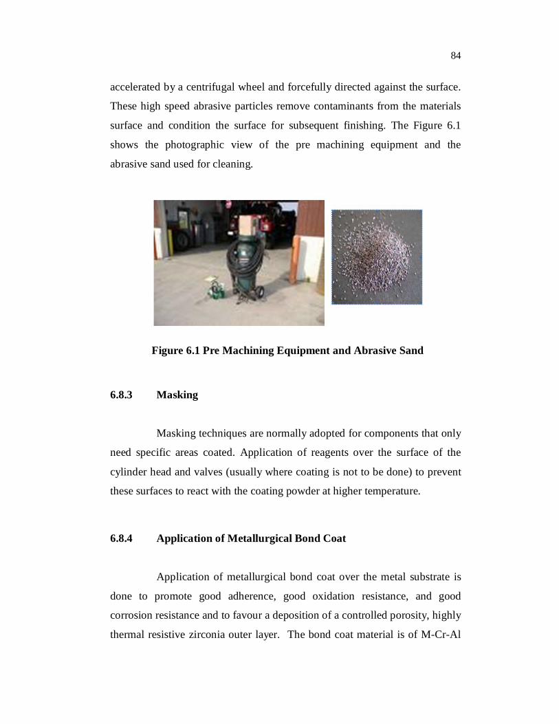
accelerated by a centrifugal wheel and forcefully directed against the surface.
These high speed abrasive particles remove contaminants from the materials
surface and condition the surface for subsequent finishing. The Figure 6.1
shows the photographic view of the pre machining equipment and the
abrasive sand used for cleaning.
Figure 6.1 Pre Machining Equipment and Abrasive Sand
6.8.3 Masking
Masking techniques are normally adopted for components that only
need specific areas coated. Application of reagents over the surface of the
cylinder head and valves (usually where coating is not to be done) to prevent
these surfaces to react with the coating powder at higher temperature.
6.8.4 Application of Metallurgical Bond Coat
Application of metallurgical bond coat over the metal substrate is
done to promote good adherence, good oxidation resistance, and good
corrosion resistance and to favour a deposition of a controlled porosity, highly
thermal resistive zirconia outer layer. The bond coat material is of M-Cr-Al

85
chemical composition; where M is Co, Ni, Fe or combinations of these
elements (Applied for a thickness of 10-15 microns).
The composition used in the present work consists of Ni+10-30%
weight Chromium+3-13 wt. % aluminum+ 0.05 to 1.0 wt. % cobalt. The bond
coat is applied using thermal spray processes using flame .In this method , the
metal surface is heated to a temperature of 600- 800 0C and the material in the
form of powder is fed into the flame by a stream of compressed air where it
gets heated due to high temperature and is directed towards the surface.
6.8.5 Application of the Powder over the Surface Using Plasma
Spraying Technique
This method uses a DC electric arc to generate a stream of high
temperature ionized plasma gas (argon), which acts as the heat source. In
plasma the electrons are stripped from the atoms creating a substance that
resembles a gas but that conducts electricity. The arc is struck between a
tungsten cathode and a copper anode within the torch. The torch is fed with a
continuous flow of inert gas, which is ionized by the DC arc and is
compressed and accelerated by the torch nozzle so that it issues from the torch
as a high velocity (500-600 m/sec), high temperature (12000-16000K) plasma
jet. The coating material in powder form is carried in an inert gas stream into
the plasma jet where it is heated and propelled towards the substrate. The
schematic setup of plasma spray technique used for the coating as shown in
Figure 6.2.

86
Figure 6.2 Plasma Spraying Technique
Parameters - Porosity %= 2-5 , Coating Adhesion= 40-70 MPa,
Current rating = 800-1000A
6.8.6 Final Machining and Grinding
Final machining process using abrasive grinding wheel or a
precision diamond cutting tool to remove excess ceramic powders adheres
over the surface.
Velocity of the cutter / RPM of grinding wheel-525 m/s (3000 rpm)
6.8.7 Polishing and Cleaning
Since the surface of the coated component will be rough after the
plasma spraying process, the surface is polished using fine abrasive over a
rotating grinding wheel. The excess coating powder is cleaned by using a
spray of compressed air at low pressure.
6.8.8 Lapping
It is a machining operation in which the two mating surfaces are
rubbed together by insertion of an abrasive material in between them to
remove any burrs, dirt etc between them and to ensure a perfect mating
87
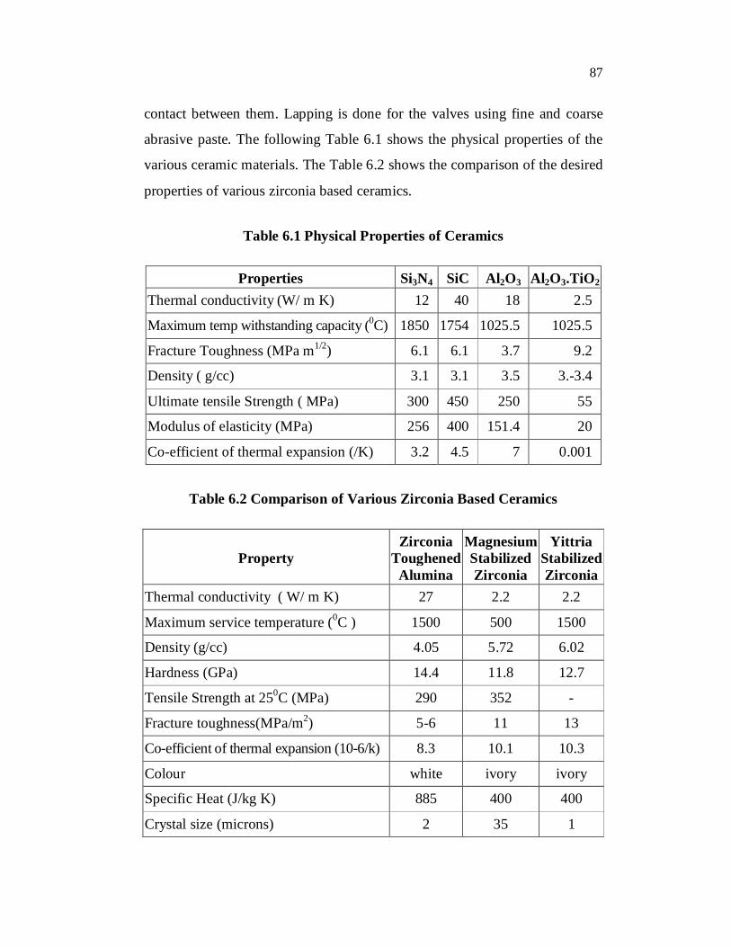
contact between them. Lapping is done for the valves using fine and coarse
abrasive paste. The following Table 6.1 shows the physical properties of the
various ceramic materials. The Table 6.2 shows the comparison of the desired
properties of various zirconia based ceramics.
Table 6.1 Physical Properties of Ceramics
Properties Si3N4 SiC Al2O3 Al2O3.TiO2
Thermal conductivity (W/ m K) 12 40 18 2.5
Maximum temp withstanding capacity (0C) 1850 1754 1025.5 1025.5
Fracture Toughness (MPa m1/2) 6.1 6.1 3.7 9.2
Density ( g/cc) 3.1 3.1 3.5 3.-3.4
Ultimate tensile Strength ( MPa) 300 450 250 55
Modulus of elasticity (MPa) 256 400 151.4 20
Co-efficient of thermal expansion (/K) 3.2 4.5 7 0.001
Table 6.2 Comparison of Various Zirconia Based Ceramics
Property Zirconia
Toughened Alumina
Magnesium Stabilized Zirconia
Yittria Stabilized Zirconia
Thermal conductivity ( W/ m K) 27 2.2 2.2
Maximum service temperature (0C ) 1500 500 1500
Density (g/cc) 4.05 5.72 6.02
Hardness (GPa) 14.4 11.8 12.7
Tensile Strength at 250C (MPa) 290 352 -
Fracture toughness(MPa/m2) 5-6 11 13
Co-efficient of thermal expansion (10-6/k) 8.3 10.1 10.3
Colour white ivory ivory
Specific Heat (J/kg K) 885 400 400
Crystal size (microns) 2 35 1

88
6.9 MATERIAL PROPERTIES AND BOUNDARY CONDITIONS
A generalized thermal boundary condition is derived to include all
thermal effects of a thin layer which is in thermal contact with an adjacent
domain. The thin layer may be a stationary or moving solid-skin or fluid-film.
The included thermal effects of the thin layer are the thermal capacity of the
layer, thermal diffusion, enthalpy flow, viscous dissipation within the layer,
convective losses from the layer, and other effects. Six different kinds of
thermal boundary conditions can be obtained as special cases of the
generalized boundary condition. The generalized boundary condition is given
for perfect and imperfect thermal contact between the thin layer and its
adjacent domain.
The ANSYS program supports six types of thermal boundary
conditions:
1. Constant temperatures
2. Constant heat fluxes
3. Applied heat transfer (film) coefficients with associated
ambient temperatures
4. Ambient radiation with associated surface emissivities and
ambient temperatures
5. Surface-to-surface radiation with associated emissivities and
enclosure number.
6. Adiabatic boundaries (the default condition)
In addition, constant volumetric heat sources may be located in
both fluid and non-fluid regions. The main aim of the thermal analysis of the
cylinder head, piston and the valves involves the calculating the convective
89
heat transfer coefficient around the combustion chamber, outer surface and
around the cooling jackets.
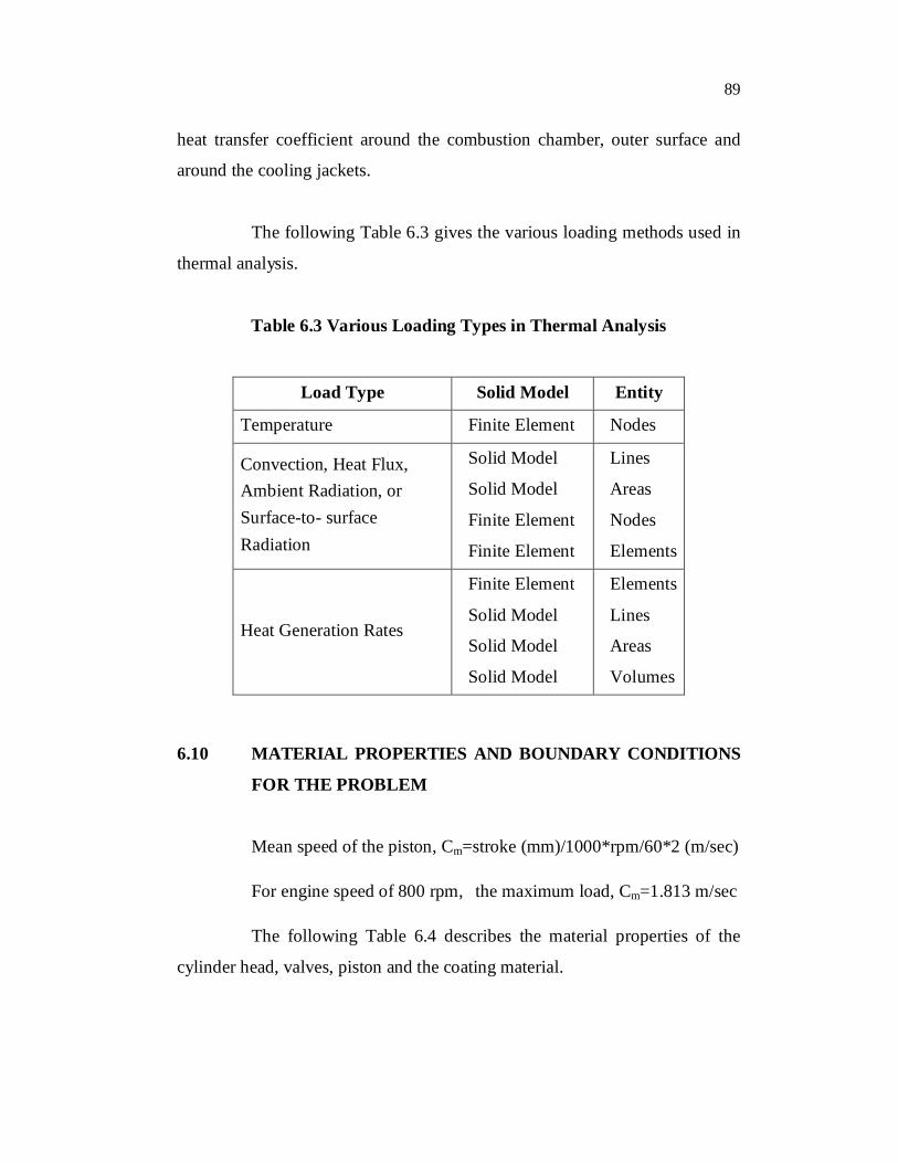
The following Table 6.3 gives the various loading methods used in
thermal analysis.
Table 6.3 Various Loading Types in Thermal Analysis
Load Type Solid Model Entity
Temperature Finite Element Nodes
Convection, Heat Flux, Ambient Radiation, or Surface-to- surface Radiation
Solid Model
Solid Model
Finite Element
Finite Element
Lines
Areas
Nodes
Elements
Heat Generation Rates
Finite Element
Solid Model
Solid Model
Solid Model
Elements
Lines
Areas
Volumes
6.10 MATERIAL PROPERTIES AND BOUNDARY CONDITIONS
FOR THE PROBLEM
Mean speed of the piston, Cm=stroke (mm)/1000*rpm/60*2 (m/sec)
For engine speed of 800 rpm, the maximum load, Cm=1.813 m/sec
The following Table 6.4 describes the material properties of the
cylinder head, valves, piston and the coating material.
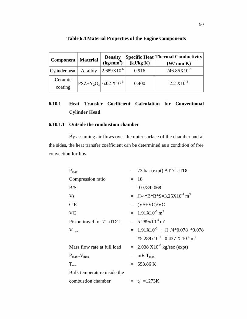
90
Table 6.4 Material Properties of the Engine Components
Component Material Density (kg/mm3)
Specific Heat (kJ/kg K)
Thermal Conductivity (W/ mm K)
Cylinder head Al alloy 2.689X10⁻⁶ 0.916 246.86X10⁻³
Ceramic coating
PSZ+Y2O3 6.02 X10⁻⁶ 0.400 2.2 X10⁻³
6.10.1 Heat Transfer Coefficient Calculation for Conventional
Cylinder Head
6.10.1.1 Outside the combustion chamber
By assuming air flows over the outer surface of the chamber and at
the sides, the heat transfer coefficient can be determined as a condition of free
convection for fins.
Pmax = 73 bar (expt) AT 70 aTDC
Compression ratio = 18
B/S = 0.078/0.068
Vs = Л/4*B*B*S=3.25X10-4 m3
C.R. = (VS+VC)/VC
VC = 1.91X10⁻⁵ m2
Piston travel for 70 aTDC = 5.289x10⁻³ m2
Vmax = 1.91X10⁻⁵ + Л /4*0.078 *0.078
*5.289x10-3 =0.437 X 10⁻⁵ m3
Mass flow rate at full load = 2.038 X10⁻³ kg/sec (expt)
Pmax *Vmax = mR Tmax
Tmax = 553.86 K
Bulk temperature inside the
combustion chamber = t0 =1273K

91
and ,temperature exposed to
outer surface (air) = ta =300 K
t= max temp = 553.86 K
(t-ta)/(t0-ta) = e-mx
=> mx = 1.3436
X= average length of the fin = 0.0475m
=> m = 28.286
Fin thickness ti = 4.33 X10⁻⁵ m
Average perimeter value = p =2(l+b)
Ac = average c/s area
Upon measurement, Ac/p = 2.164 X10⁻⁵ m
M = (p*h)/(K*Ac)
H = 4.275 X10⁻⁶ W/mm2K
6.10.1.2 Inside the Combustion Chamber
The fluid properties at the combustion chamber temperature are
given below in the following table.
According to Annand’s equation ,
hinner=a*(k/B)* Re 0.7+C/(Tg-Tw)*((0.01*Tg)4 -(0.01*Tw)4)kcal/hr m2 K
where,
a = 0.35 to 0.8 increasing with increased engine speeds
B = bore of the cylinder (m)=0.078 m
C = 2.81 for CI engines
k = thermal conductivity of the gas in kcal/hr m2 k
= 0.0871W/m
k = 0.0694 kcal/hr m2 K
ν = kinematic viscosity of the gas = 178 X 10-6 m2/sec
Tg = 1273 K

92
Tw = 553.86K
Re = B *Cm / ν = 0.7945*103
Using this
equation, hinner = 151.3807 kcal/hr m2 K = 1.76*10-4 W/mm2 K
6.10.2 Heat Transfer Coefficient Calculation for Conventional Cylinder
Head
6.10.2.1 Outside the combustion chamber
Pmax = 77 bar (expt) AT 70 aTDC
Compression ratio = 18
B/S = 0.078/0.068
Vs = Л /4*B*B*S=3.25X10-4 m3
C.R. = (VS+VC)/VC
VC = 1.91X10⁻⁵ m2
Piston travel for 70Atdc = 5.289x10⁻³ m2
Vmax = 1.91X10⁻⁵+ Л /4*0.078*0.078*5.289x10-3
= 4.437 X 10⁻⁵ m2
Mass flow rate at full load = 1.941 X10⁻³ kg/sec (expt)
Pmax *Vmax = mR Tmax
Tmax = 613.3 K
Bulk temperature inside
the combustion chamber = t0 =1273K
temperature exposed to
outer surface (air) = ta =300 K
t = max temp =613.3 K
(t-ta)/(t0-ta) = e-mx
mx = 1.133
x = average length of the fin = 0.0475m
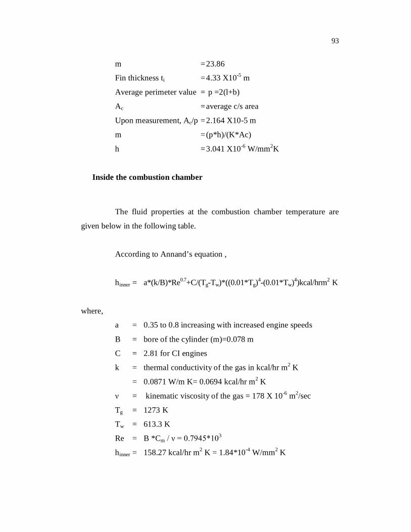
93
m = 23.86
Fin thickness ti = 4.33 X10⁻⁵ m
Average perimeter value = p =2(l+b)
Ac = average c/s area
Upon measurement, Ac/p = 2.164 X10⁻⁵ m
m = (p*h)/(K*Ac)
h = 3.041 X10⁻⁶ W/mm2K
Inside the combustion chamber
The fluid properties at the combustion chamber temperature are
given below in the following table.
According to Annand’s equation ,
hinner = a*(k/B)*Re0.7+C/(Tg-Tw)*((0.01*Tg)4-(0.01*Tw)4)kcal/hrm2 K
where,
a = 0.35 to 0.8 increasing with increased engine speeds
B = bore of the cylinder (m)=0.078 m
C = 2.81 for CI engines
k = thermal conductivity of the gas in kcal/hr m2 K
= 0.0871 W/m K= 0.0694 kcal/hr m2 K
ν = kinematic viscosity of the gas = 178 X 10-6 m2/sec
Tg = 1273 K
Tw = 613.3 K
Re = B *Cm / ν = 0.7945*103
hinner = 158.27 kcal/hr m2 K = 1.84*10-4 W/mm2 K
94
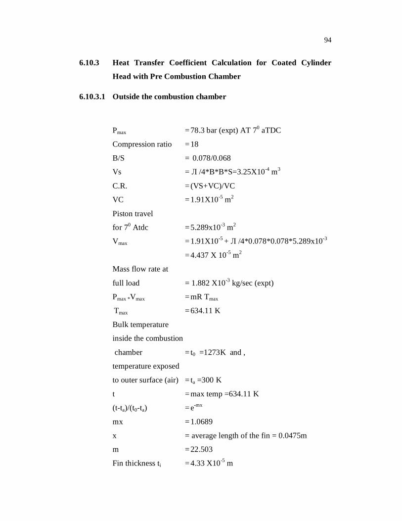
6.10.3 Heat Transfer Coefficient Calculation for Coated Cylinder
Head with Pre Combustion Chamber
6.10.3.1 Outside the combustion chamber
Pmax = 78.3 bar (expt) AT 70 aTDC
Compression ratio = 18
B/S = 0.078/0.068
Vs = Л /4*B*B*S=3.25X10-4 m3
C.R. = (VS+VC)/VC
VC = 1.91X10⁻⁵ m2
Piston travel
for 70 Atdc = 5.289x10⁻³ m2
Vmax = 1.91X10⁻⁵ + Л /4*0.078*0.078*5.289x10-3
= 4.437 X 10⁻⁵ m2
Mass flow rate at
full load = 1.882 X10⁻³ kg/sec (expt)
Pmax *Vmax = mR Tmax
Tmax = 634.11 K
Bulk temperature
inside the combustion
chamber = t0 =1273K and ,
temperature exposed
to outer surface (air) = ta =300 K
t = max temp =634.11 K
(t-ta)/(t0-ta) = e-mx
mx = 1.0689
x = average length of the fin = 0.0475m
m = 22.503
Fin thickness ti = 4.33 X10⁻⁵ m
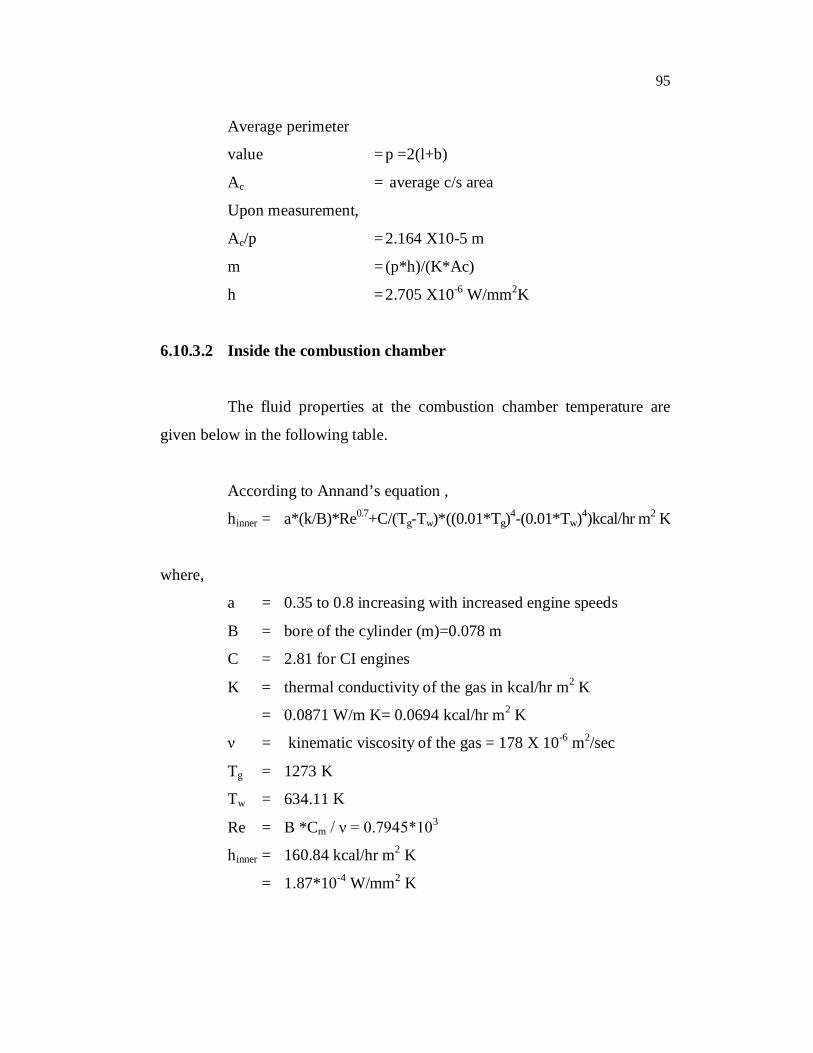
95
Average perimeter
value = p =2(l+b)
Ac = average c/s area
Upon measurement,
Ac/p = 2.164 X10⁻⁵ m
m = (p*h)/(K*Ac)
h = 2.705 X10⁻⁶ W/mm2K
6.10.3.2 Inside the combustion chamber
The fluid properties at the combustion chamber temperature are
given below in the following table.
According to Annand’s equation ,
hinner = a*(k/B)*Re0.7+C/(Tg-Tw)*((0.01*Tg)4-(0.01*Tw)4)kcal/hr m2 K
where,
a = 0.35 to 0.8 increasing with increased engine speeds
B = bore of the cylinder (m)=0.078 m
C = 2.81 for CI engines
K = thermal conductivity of the gas in kcal/hr m2 K
= 0.0871 W/m K= 0.0694 kcal/hr m2 K
ν = kinematic viscosity of the gas = 178 X 10-6 m2/sec
Tg = 1273 K
Tw = 634.11 K
Re = B *Cm / ν = 0.7945*103
hinner = 160.84 kcal/hr m2 K
= 1.87*10-4 W/mm2 K
96
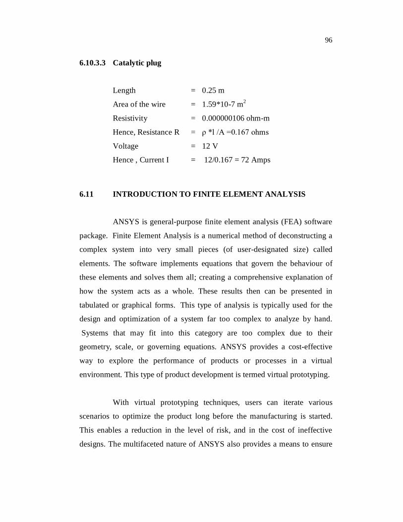
6.10.3.3 Catalytic plug
Length = 0.25 m
Area of the wire = 1.59*10-7 m2
Resistivity = 0.000000106 ohm-m
Hence, Resistance R = ρ *l /A =0.167 ohms
Voltage = 12 V
Hence , Current I = 12/0.167 = 72 Amps
6.11 INTRODUCTION TO FINITE ELEMENT ANALYSIS
ANSYS is general-purpose finite element analysis (FEA) software
package. Finite Element Analysis is a numerical method of deconstructing a
complex system into very small pieces (of user-designated size) called
elements. The software implements equations that govern the behaviour of
these elements and solves them all; creating a comprehensive explanation of
how the system acts as a whole. These results then can be presented in
tabulated or graphical forms. This type of analysis is typically used for the
design and optimization of a system far too complex to analyze by hand.
Systems that may fit into this category are too complex due to their
geometry, scale, or governing equations. ANSYS provides a cost-effective
way to explore the performance of products or processes in a virtual
environment. This type of product development is termed virtual prototyping.
With virtual prototyping techniques, users can iterate various
scenarios to optimize the product long before the manufacturing is started.
This enables a reduction in the level of risk, and in the cost of ineffective
designs. The multifaceted nature of ANSYS also provides a means to ensure
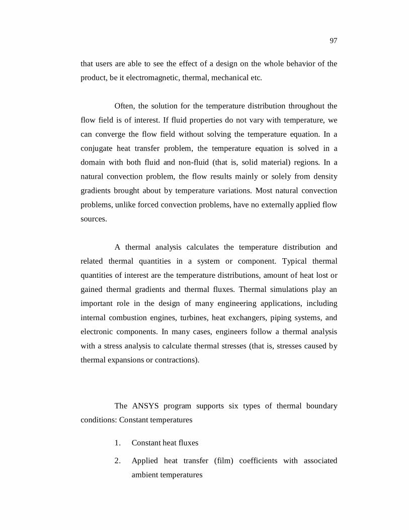
97
that users are able to see the effect of a design on the whole behavior of the
product, be it electromagnetic, thermal, mechanical etc.
Often, the solution for the temperature distribution throughout the
flow field is of interest. If fluid properties do not vary with temperature, we
can converge the flow field without solving the temperature equation. In a
conjugate heat transfer problem, the temperature equation is solved in a
domain with both fluid and non-fluid (that is, solid material) regions. In a
natural convection problem, the flow results mainly or solely from density
gradients brought about by temperature variations. Most natural convection
problems, unlike forced convection problems, have no externally applied flow
sources.
A thermal analysis calculates the temperature distribution and
related thermal quantities in a system or component. Typical thermal
quantities of interest are the temperature distributions, amount of heat lost or
gained thermal gradients and thermal fluxes. Thermal simulations play an
important role in the design of many engineering applications, including
internal combustion engines, turbines, heat exchangers, piping systems, and
electronic components. In many cases, engineers follow a thermal analysis
with a stress analysis to calculate thermal stresses (that is, stresses caused by
thermal expansions or contractions).
The ANSYS program supports six types of thermal boundary
conditions: Constant temperatures
1. Constant heat fluxes
2. Applied heat transfer (film) coefficients with associated
ambient temperatures

98
3. Ambient radiation with associated surface emissivities and
ambient temperatures
4. Surface-to-surface radiation with associated emissivities and
enclosure number.
5. Adiabatic boundaries (the default condition)
ANSYS supports two types of thermal analysis:
1. A steady-state thermal analysis determines the temperature
distribution and other thermal quantities under steady-state
loading conditions. A steady-state loading condition is a
situation where heat storage effects varying over a period of
time can be ignored.
2. A transient thermal analysis determines the temperature
distribution and other thermal quantities under conditions that
vary over a period of time.
6.11.1 Solid 90 Element
SOLID90 is of the 3-D eight nodes thermal element .The element
has 20 nodes with a single degree of freedom, temperature, at each node. The
20-node elements have compatible temperature shapes and are well suited to
model curved boundaries. The 20-node thermal element is applicable to a 3-
D, steady-state or transient thermal analysis.
6.11.2 Assumptions
1. The element must not have a zero volume. This occurs most
frequently when the element is not numbered properly.

99
2. A prism or tetrahedron shaped element may be formed by
defining duplicate node numbers as in Triangle, Prism and
Tetrahedral Elements.
3. The specific heat and enthalpy are evaluated at each
integration point to allow for abrupt changes (such as for
melting) within a coarse grid.
4. If the thermal element is to be replaced by a SOLID45
structural element with surface stresses requested, the thermal
element should be oriented such that face I-J-N-M and/or face
K-L-P-O is a free surface.
5. A free surface of the element (that is, not adjacent to another
element and not subjected to a boundary constraint) is
assumed to be adiabatic.
6. Thermal transients having a fine integration time step and a
severe thermal gradient at the surface will also require a fine
mesh at the surface.
The element is defined by 20 node points and the material
properties. A prism-shaped element may be formed by defining duplicate K,
L, and S; A and B; and O, P, and W node numbers. A tetrahedral-shaped
element and a pyramid-shaped element may also be formed as shown in the
Figure 6.3. Orthotropic material directions correspond to the element
coordinate directions. The element coordinate system orientation is as
described in Coordinate Systems. Specific heat and density are ignored for
steady-state solutions. Convection or heat flux (but not both) and radiation
may be input as surface loads at the element faces as shown by the circled
numbers on the Figure 6.3. Heat generation rates may be input as element
body loads at the nodes. If the node I heat generation rate HG (I) is input, and
all others are unspecified, they default to HG (I). If all corner node heat

100
generation rates are specified, each mid side node heat generation rate
defaults to the average heat generation rate of its adjacent corner nodes.
6.11.3 Input Data
1. Nodes : I, J, K, L, M, N, O, P, Q, R, S, T, U, V, W, X, Y, Z, A, B
2. Degrees of Freedom: TEMP
3. Real Constants: None
4. Material Properties: KXX, KYY, KZZ, DENS, C, ENTH
5. Surface Loads: Convection or Heat Flux (but not both) and
Radiation
face 1 (J-I-L-K), face 2 (I-J-N-M), face 3 (J-K-O-N),
face 4 (K-L-P-O), face 5 (L-I-M-P), face 6 (M-N-O-P)
6. Body Loads: Heat Generations --
HG(I), HG(J), HG(K), HG(L), HG(M), HG(N), HG(O),
HG(P), HG(Q), HG(R),
HG(S), HG(T), HG(U), HG(V), HG(W), HG(X), HG(Y),
HG(Z), HG(A), HG(B)
Figure 6.3 Solid 90 Element
101
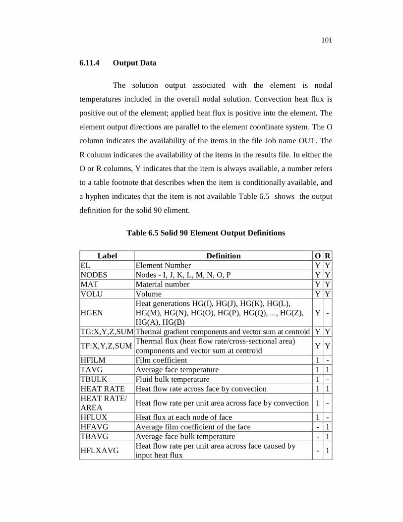
6.11.4 Output Data
The solution output associated with the element is nodal
temperatures included in the overall nodal solution. Convection heat flux is
positive out of the element; applied heat flux is positive into the element. The
element output directions are parallel to the element coordinate system. The O
column indicates the availability of the items in the file Job name OUT. The
R column indicates the availability of the items in the results file. In either the
O or R columns, Y indicates that the item is always available, a number refers
to a table footnote that describes when the item is conditionally available, and
a hyphen indicates that the item is not available Table 6.5 shows the output
definition for the solid 90 eliment.
Table 6.5 Solid 90 Element Output Definitions
Label Definition O R EL Element Number Y Y NODES Nodes - I, J, K, L, M, N, O, P Y Y MAT Material number Y Y VOLU Volume Y Y
HGEN Heat generations HG(I), HG(J), HG(K), HG(L), HG(M), HG(N), HG(O), HG(P), HG(Q), ..., HG(Z), HG(A), HG(B)
Y -
TG:X,Y,Z,SUM Thermal gradient components and vector sum at centroid Y Y
TF:X,Y,Z,SUM Thermal flux (heat flow rate/cross-sectional area) components and vector sum at centroid Y Y
HFILM Film coefficient 1 - TAVG Average face temperature 1 1 TBULK Fluid bulk temperature 1 - HEAT RATE Heat flow rate across face by convection 1 1 HEAT RATE/ AREA Heat flow rate per unit area across face by convection 1 -
HFLUX Heat flux at each node of face 1 - HFAVG Average film coefficient of the face - 1 TBAVG Average face bulk temperature - 1
HFLXAVG Heat flow rate per unit area across face caused by input heat flux - 1

102
6.12 STEPS INVOLVED IN THERMAL ANALYSIS
The following steps are involved in solving the cylinder head and
valves for thermal analysis:
6.12.1 Specify the Type of Analysis
Since we are interested in knowing the temperature distribution
around the cylinder head and valves, click “PREFERENCES” and check
“ON” the “Thermal” radio button.
6.12.2 Importing the Model from 3d Modelling Software
The model created in Solid works 2005 is saved as an “iges” or
“igs” file. Then the required file is imported in ANSYS using the following
commands:
(a) Go to “FILE” pull down menu bar and Click “IMPORT
IGES”.
(b) Set import option as “de-feature model” and click “OK” and
Specify the path name of the “iges” file to be imported.
6.12.3 Preprocessing
This refers to the various input data required for thermal analysis.
They may include type of the element (basic form of the model), material
properties, modeling (if required), meshing to the precise mesh density and
creating nodes and elements by meshing the model. The following parameters
are required in preprocessing:
103
6.12.3.1 Define Element Type
Select thermal element “SOLID 90” which possesses all the
characteristics required to perform the analysis. Choose
PREPROCESSORELEMENT TYPEADD/EDIT/DELETE. Select
Thermal Solid 20 node 90 element.
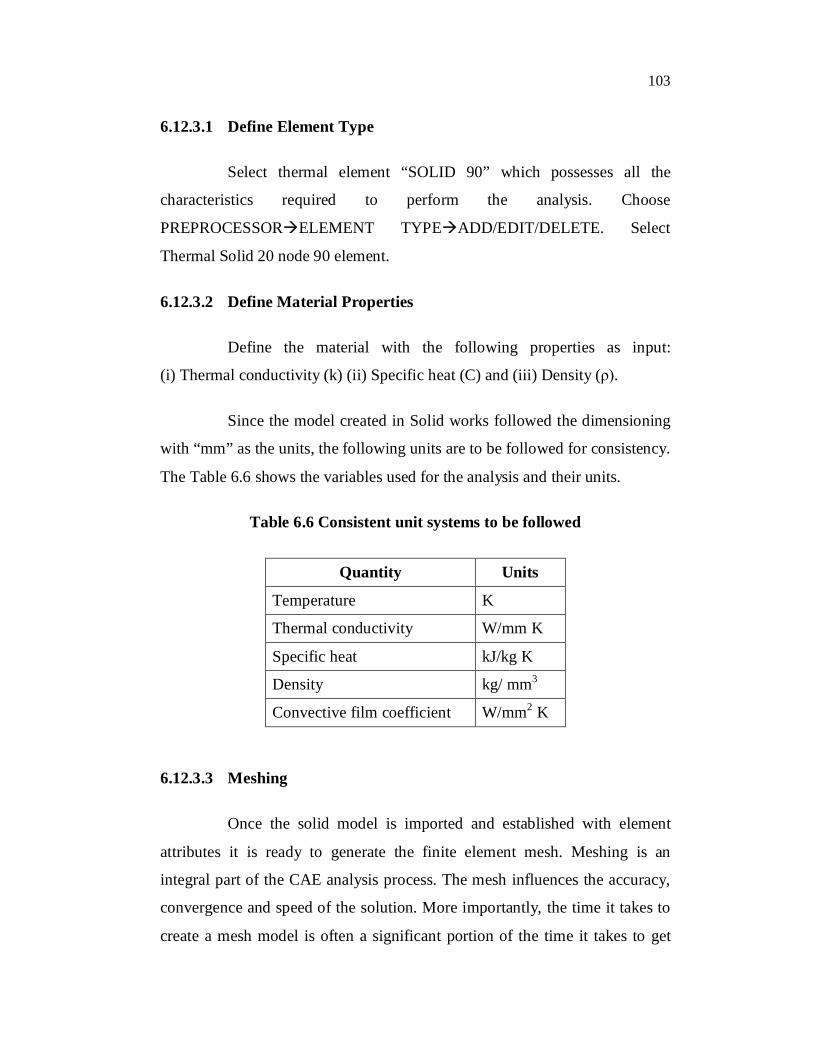
6.12.3.2 Define Material Properties
Define the material with the following properties as input:
(i) Thermal conductivity (k) (ii) Specific heat (C) and (iii) Density (ρ).
Since the model created in Solid works followed the dimensioning
with “mm” as the units, the following units are to be followed for consistency.
The Table 6.6 shows the variables used for the analysis and their units.
Table 6.6 Consistent unit systems to be followed
Quantity Units
Temperature K
Thermal conductivity W/mm K
Specific heat kJ/kg K
Density kg/ mm3
Convective film coefficient W/mm2 K
6.12.3.3 Meshing
Once the solid model is imported and established with element
attributes it is ready to generate the finite element mesh. Meshing is an
integral part of the CAE analysis process. The mesh influences the accuracy,
convergence and speed of the solution. More importantly, the time it takes to
create a mesh model is often a significant portion of the time it takes to get
104
results from a CAE solution. Therefore, the better and more automated the
meshing tools, the better the solution.
As an assembly drawing is being imported, select the volumes
individually for which the meshing has to be done. The following steps are to
be followed:
(i) Specify the properties for that volume i.e. the element
properties .Choose MESHING MESHED ATTRIBUTES
PICKED VOLUME. Select the volume. Apply the element
properties and click OK.
(ii) Mesh the given model: Choose MESH TOOL and move the
smart size tab to “1” for increased accuracy and then click
MESH option. Select the volume (as in step (i)) to be meshed
by clicking OK. The geometry is meshed using tetragonal
elements with free meshing. Repeat steps (i) and (ii) for all the
volumes and change the element properties as desired.
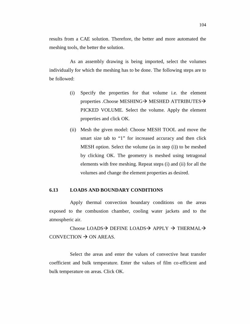
6.13 LOADS AND BOUNDARY CONDITIONS
Apply thermal convection boundary conditions on the areas
exposed to the combustion chamber, cooling water jackets and to the
atmospheric air.
Choose LOADS DEFINE LOADS APPLY THERMAL
CONVECTION ON AREAS.
Select the areas and enter the values of convective heat transfer
coefficient and bulk temperature. Enter the values of film co-efficient and
bulk temperature on areas. Click OK.
105
Apply the convection boundary conditions for other areas. Check
the load values on each surface using the option:
LIST LOADSSURFACE ON ALL AREAS
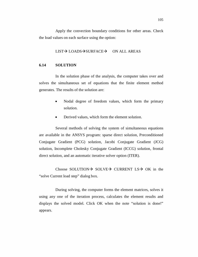
6.14 SOLUTION
In the solution phase of the analysis, the computer takes over and
solves the simultaneous set of equations that the finite element method
generates. The results of the solution are:
Nodal degree of freedom values, which form the primary
solution.
Derived values, which form the element solution.
Several methods of solving the system of simultaneous equations
are available in the ANSYS program: sparse direct solution, Preconditioned
Conjugate Gradient (PCG) solution, Jacobi Conjugate Gradient (JCG)
solution, Incomplete Cholesky Conjugate Gradient (ICCG) solution, frontal
direct solution, and an automatic iterative solver option (ITER).
Choose SOLUTION SOLVE CURRENT LS OK in the
“solve Current load step” dialog box.
During solving, the computer forms the element matrices, solves it
using any one of the iteration process, calculates the element results and
displays the solved model. Click OK when the note “solution is done!”
appears.

106
6.15 POST PROCESSING
After building the model and obtaining the solution, the answers to
some critical questions like how does the temperature of this part vary with
time, what is the heat loss across this face of the model etc will be answered
by the postprocessors . Post processing means reviewing the results of an
analysis. It is probably the most important step in the analysis, because we are
trying to understand how the applied loads affect the design, how good the
finite element mesh is, and so on. Post processing helps to plot the
temperature distribution across the model. Choose GENERAL
POSTPROCPLOT RESULTS CONTOUR PLOT NODAL SOLU
DOF SOLUTION and pick “Temperature TEMP”, and then click OK.
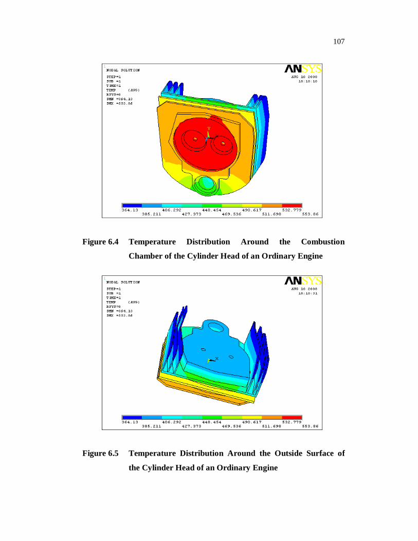
6.16 RESULTS-TEMPERATURE DISTRIBUTION PLOTS
The thermal analysis of the cylinder head considering no coating
and with coating is performed by applying the material properties and the
boundary conditions. The Figures 6.4 and 6.5 illustrates the temperature
distribution around the cylinder head of a conventional engine while the
Figures 6.6 and 6.7 shows for a LHR engine and Figures 6.9 and 6.10
illustrates for the coated engine with pre combustion chamber.
It can be concluded that the combustion chamber surface
temperature is highest in the case of coated head with pre combustion
chamber. The maximum temperature after the coating is around 613 K. For
the coated head with pre combustion chamber, due to the presence of catalytic
plug, maximum temperature is 634.11K. The self ignition temperature of
Aquanol is around 820 K. But the surface temperature is sufficiently lower
than the self ignition temperature of the fuel. So it will avoid the pre ignition
of the fuel and the coating will improve the vaporization of the fuel.
107
Figure 6.4 Temperature Distribution Around the Combustion
Chamber of the Cylinder Head of an Ordinary Engine
Figure 6.5 Temperature Distribution Around the Outside Surface of
the Cylinder Head of an Ordinary Engine

108
Figure 6.6 Temperature Distribution Around the Combustion
Chamber of the Cylinder Head of a Coated Engine
Figure 6.7 Temperature Distribution Around the Outer Surface of the
Cylinder Head of a Coated Engine

109
Figure 6.8 Coated Engine with Pre Combustion Chamber
Figure 6.9 Temperature Distribution Around the Combustion
Chamber of the Cylinder Head of a Coated Engine With Pre
Combustion Chamber

110
Figure 6.10 Temperature Distribution Around the outer Surface of the
Cylinder Head of a Coated Engine with Pre Combustion
Chamber