
Chapter 6 Network architecture Supporting Wireless Applications
21
Chapter 6 Network architecture Supporting Wireless Applications
Transcript of Chapter 6 Network architecture Supporting Wireless Applications

Chapter 6Network architecture
SupportingWireless Applications

WAE Architecture

WAE Architecture

WAE Architecture

WAE Architecture

WTA Architecture• Wireless Telephony Application• Application framework for telephony services• WTA user agent – capability for interfacing with mobile
network services available to mobile telephony device.• ie. Setting up and receiving phone calls.• WTA service include :-
– Extended set of user options for handling incoming calls
– Voice mail– Call subscriber from message list or log.

WTA Architecture

WTA Architecture

WTA Architecture

WTA Architecture

WTA Architecture
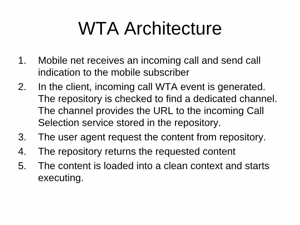
WTA Architecture1. Mobile net receives an incoming call and send call
indication to the mobile subscriber2. In the client, incoming call WTA event is generated.
The repository is checked to find a dedicated channel. The channel provides the URL to the incoming Call Selection service stored in the repository.
3. The user agent request the content from repository.4. The repository returns the requested content5. The content is loaded into a clean context and starts
executing.

WTA Architecture6. A connect request is sent to the mobile network7. A connect ACK is generated in the mobile network. A
result code indicating the outcome of the calls is generated internally in the phone.
8. A speech path between the mobile network and the client is established.

WTA Architecture

WTA Architecture1. The voice mail system notifies the WTA server that
there are new voice mails. A list of voice mails is also sent to the WTA server.
2. The WTA server creates new service content on the basis of the list received from the voice mail system.
3. The WAP gateway sends the SI to the client using push.
4. The user notified about SI by a message delivered with the SI. The user chooses to accept the SI
5. A WSP Get request is sent to the WAP gateway (URL provided by the SI)

WTA Architecture6. The WAP gateway makes a WSP/HTTP conversion.7. The WTA server returns the earlier created voice mail
service.8. The WAP gateway makes an HTTP/WSP conversion.9. The voice mail service is now executing in the client.
The user is presented with a list of voice mails originating from the voice mail system. The user select the voice mail to listen to.
10. Another WSP Get request is sent to the WAP gateway. The requested deck identifies the selected voice mail.
11. The WAP gateway makes WSP/HTTP conversion.

WTA Architecture12. The WTA server returns the requested deck. The deck
only contains one card with a single WTA-WML task.13. The WAP gateway makes an HTTP/WSP conversion.14. The incoming call event is temporarily bound so that
the call from the voice mail will be answered automatically
15. The WTA server instructs the voice mail system to play selected voice mail.
16. The voice mail system instruct the mobile network to set up a call to the client.
17. The mobile net set up a call to the client

WTA Architecture18. The client answers the call automatically as a result of
the content loaded in steps 12 to 1419. The mobile network informs the voice mail system that
the client has accepted the call20. ACKs are sent to the client and the voice mail system21. A speech path is established between the Voice Mail
System and the client, and the message is played.

WAP Push Architecture
• Introduce a means within the WAP effort to transmit information to a device without previous user action.

WAP Push Architecture
• Push OTA & PAP
• OTAProtocol – WSP service, PAP – XML messages.

• Service perform by PPG– Push Initiator, authentication, access control– Parsing of error detection in content control
information– Client discovery services– Address resolution– Binary encoding and compilation of certain content
types to improve efficiency of OTA– Protocol conversion
WAP Push Architecture


![Wireless Architecture[1]](https://static.fdocuments.in/doc/165x107/577ce4561a28abf1038e1f1b/wireless-architecture1.jpg)


