
Chapter 1, Wireless System Architecture: How Wireless Works
39
Chapter 1, Wireless System Architecture: How Wireless Works Author: Jim Geier Principal Consultant, Wireless-Nets, Ltd. Email: [email protected] This chapter is a sample from the book Wireless Networks first-step, written by Jim Geier and made available with permission from Cisco Press. Independent Consulting Services www.wireless-nets.com Copyright 2008, Wireless-Nets, Ltd.
Transcript of Chapter 1, Wireless System Architecture: How Wireless Works

Chapter 1, Wireless System Architecture: How Wireless Works
Author: Jim Geier
Principal Consultant, Wireless-Nets, Ltd.
Email: [email protected]
This chapter is a sample from the book Wireless Networks first-step, written by Jim Geier and made available with permission from Cisco Press.
Independent Consulting Services
www.wireless-nets.com
Copyright 2008, Wireless-Nets, Ltd.

What You Will LearnAfter reading this chapter, you should be able to
✔ Understand the components of a wireless network
✔ Discover general wireless network architectural elements
✔ Understand how information flows through a wireless network
1119fmF.book Page 30 Wednesday, July 7, 2004 7:39 AM

CHAPTER 2
Wireless System Architecture: How Wireless Works
Wireless networks utilize components similar to wired networks; however, wire-less networks must convert information signals into a form suitable for transmis-sion through the air medium. Even though wireless networks directly contribute only to a portion of the overall network infrastructure, attention to all network functions is necessary to counter impairments resulting from the wireless medium. This chapter discusses concepts common to all types of wireless net-works, with emphasis on components and information signals.
Wireless Network System ComponentsA wireless network consists of several components that support communications using radio or light waves propagating through an air medium. Some of these ele-ments overlap with those of wired networks, but special consideration is neces-sary for all of these components when deploying a wireless network. Figure 2-1 illustrates these primary components.
Figure 2-1 Wireless Networks Include Computer Devices, Base Stations, and a Wireless Infrastructure
ComputerDevices
Base Station
WirelessInfrastructure
Base Station
1119fmF.book Page 31 Wednesday, July 7, 2004 7:39 AM

32 Chapter 2: Wireless System Architecture: How Wireless Works
Users
A user can be anything that directly utilizes the wireless network. One of the most common types of user is a person. For example, a business traveler accessing the Internet from a public wireless LAN at an airport is a user. In some cases, how-ever, the user might not be human. A robot, for example, might receive instruc-tions over a wireless network from a central computer that controls a manu-facturing process. Because the wireless network exists to serve the user, the user is the component that receives the benefits of a wireless network. As a result, users are an important part of the wireless network.
The user initiates and terminates use of a wireless network, making the term end-user appropriate. Typically, a user operates a computer device, which often per-forms a variety of application-specific functions in addition to offering an inter-face to the wireless network.
Users of wireless networks tend to be mobile, constantly moving throughout a facility, campus, or city. Mobility is one of the most prominent benefits of deploy-ing a wireless network. For example, a person walking through a convention cen-ter while sending and receiving e-mail from a PDA is exercising mobility. The PDA in this case must have continual or frequent connections to a wireless net-work infrastructure.
Some users might require only portability; whereby, they stay at a particular loca-tion while using the wireless network for a specific period of time. An example of this type of usage is someone operating a laptop wirelessly from a conference room. The user will turn on the laptop after sitting down in the conference room and shut off the laptop before leaving. As a result, the wireless network doesn’t need to support continual movement.
Other users might actually be stationary, which means that they operate from one place for an indefinite period of time. An example of this type of user is someone working from a wireless computer in an office. The biggest difference between a stationary and portable user is that the stationary user will not require any form of roaming functions. Roaming functions are difficult to implement in some situations.
1119fmF.book Page 32 Wednesday, July 7, 2004 7:39 AM

Wireless Network System Components 33
Computer Devices
Many types of computer devices, sometimes referred to as clients, operate on a wireless network. Some computer devices might be specifically designed for users, whereas some computer devices are end systems. In generally, any com-puter device might communicate with any other computer device on the same wireless network. Figure 2-2 illustrates an assortment of computer devices for wireless networks.
Figure 2-2 Computer Devices for Wireless Networks Satisfy Differ-ent Applications
To support mobile applications, computer devices are often small, making them practical for people to carry with them at all times. These devices generally have small screens, limited keyboards, and small batteries. The devices are mobile, but they can support only certain applications.
With portable and stationary applications, however, the computer devices are much larger. These devices generally have larger displays and keyboards, making them more suitable to use when browsing the Internet and other applications requiring relatively high performance. The problem, however, is that these devices weigh more and are difficult to carry from one place to another.
Mobile Phone Laptop
PersonalDigital
Assistant
Desktop PC
Printer
Desk Phone
Data Collector
1119fmF.book Page 33 Wednesday, July 7, 2004 7:39 AM

34 Chapter 2: Wireless System Architecture: How Wireless Works
Computer devices within a wireless network also include end systems such as servers, databases, and websites. For example, the http://www.cnn.com website includes news that someone can view from a public wireless LAN connection from a hotel room. Similarly, a clerk can wirelessly interface with a warehouse management system, which acts as an end-system computer device.
Users can adapt many existing computer devices to operate on a wireless network. A user, for example, can purchase and install a wireless network interface card (NIC) within his laptop to enable operation on a particular type of wireless net-work. Some devices, such as a wireless bar code scanner, operate only on a wire-less network.
A computer device also has an operating system, such as Windows XP, LINUX, or MAC OS. The operating system runs software needed to realize the wireless network application. In some cases, the operating system has built-in features that enhance wireless networks. For example, Windows XP has the ability to automat-ically identify and associate with wireless LANs.
NICs
The
network interface card
provides the interface between the computer device and the wireless network infrastructure. The NIC fits inside the computer device, but external network adaptors are available that plug in and remain outside the computer device. Figure 2-3 shows examples of several types of wireless NICs.
Figure 2-3
Wireless NICs Have Various Types of Form Factors
111902i.fm Page 34 Wednesday, July 7, 2004 1:30 PM

Wireless Network System Components 35
Wireless network standards define how a wireless NIC operates. For example, a wireless LAN NIC might implement the IEEE 802.11b standard. In this case, the wireless NIC will only be able to interface with a wireless network infrastructure that complies with the 802.11b standard. As a result, users must be careful to ensure that the wireless NIC they choose matches the type of wireless network infrastructure they want to access.
Wireless NICs also comply with a specific form factor, which defines the physical and electrical bus interface that enables the card to communicate with the com-puter device. Again, the user must consider this to ensure that the chosen wireless NIC will fit within their computer device. The following is a summary of the dif-ferent internal form factors available for wireless networks:
■ Industry-Standard Architecture (ISA)—ISA has been around since the early 1980s. Because of this, the proliferation of the ISA bus has been sig-nificant. Despite its limited performance, nearly all PCs manufactured up until recently had at least one ISA bus. The ISA bus has failed, however, to advance at the pace of the rest of the computer world, and other higher-speed alternatives are now available. ISA doesn’t impose too much of a perfor-mance impact on 802.11b wireless LANs. It’s not advisable, however, to purchase new ISA cards because of the possibility of them becoming obso-lete.
■ Peripheral Component Interconnect (PCI)—The PCI bus is the most popular interface for PCs today and boasts high performance. Intel origi-nally developed and released PCI in 1993, and it satisfies the needs of the recent generations of PCs for multimedia and graphics. PCI cards were the first to popularize “plug-and-play” technology, which makes it easy to install the NIC. PCI circuitry can recognize compatible PCI cards and work with the computer’s operating system to set the configurations for each card. This saves time and prevents installation headaches for nontechnical users.
■ PC Card—The PC Card was developed in the early 1990s by the Personal Computer Memory Card International Association (PCMCIA). The PC Card is a credit-card-sized device that provides extended memory, modems, connectivity to external devices, as well as wireless LAN capabilities to small computer devices such as laptops and PDAs. In fact, they are the most
1119fmF.book Page 35 Wednesday, July 7, 2004 7:39 AM

36 Chapter 2: Wireless System Architecture: How Wireless Works
widely available NICs available. They are more popular than ISA or PCI cards because of use in a growing number of laptops and PDAs.
It’s possible to share a PC Card with a desktop PC by using an adaptor that converts a PC Card into a PCI card. This allows purchasing one NIC for use in both types of computers. You can take the PC Card with you on a business trip— or home from work— and utilize the same card when back in the office using a PC. Some PDAs require a sled device that accommodates the PC Card and mounts underneath the PDA. This is the only way to add wire-less network capability to some older PDAs. The combination of the sled, PC Card and PDA, however, adds a lot of bulk and weight that depletes the usability.
■ Mini-PCI—A Mini-PCI card is a smaller version of a standard desktop PCI card and fits well within small, mobile computer devices. It has all the same features and functionality of a normal PCI card, but is about one quarter the size. Mini-PCI cards are integrated within laptops as an option to buyers. A strong advantage of this form of radio NIC is that it frees up the PC Card slot for other devices, such as memory extenders and graphics accelerators. In addition, manufacturers can provide Mini-PCI–based wireless NICs at lower costs. The Mini-PCI card is not without disadvantages, however. The replacement of a Mini-PCI card typically requires the disassembly of the laptop, which might void the manufacturer’s warranty. Mini-PCI cards might also lead to lower performance because they require the computer to do some, if not all, of the processing. Despite these drawbacks, the Mini-PCI card is becoming a solid technology in the wireless laptop world.
■ CompactFlash—SanDisk Corporation first introduced CompactFlash (CF) in 1994, but wireless NICs were not available in CF form factors until recently. A CF card is small, weighing half an ounce, and is less than half the thickness of a PC Card. It also holds only one quarter the volume of PC Card radio card. The CF cards draw little power, which enables the batteries to last longer than devices using PC Cards. Some PDAs come with direct CF interfaces, which results in a lightweight and compact wireless PDA. If the computer device doesn’t have a CF slot, you can purchase an adapter so that the CF card will fit into a standard PC Card slot. A CF radio card is defi-nitely the way to go, especially for compact computing devices.
1119fmF.book Page 36 Wednesday, July 7, 2004 7:39 AM

Wireless Network System Components 37
In addition to the internal NICs, a variety of external network interfaces connect to the computer device through parallel, serial, and USB ports. These might be suitable for stationary computers, but they certainly hinder mobility in most wire-less applications.
As Chapter 3, “Radio Frequency and Light Signal Fundamentals: The Invisible Medium,” discusses in detail, a wireless NIC includes an antenna that converts electrical signals to radio or light waves for propagation through the air medium. Antennae employ many structures, and they can be external, internal, permanent, or detachable. The antenna for a PC Card, for example, generally attaches to the end of the card and protrudes out the side of the laptop.
Mini-PCI cards, however, might have an antenna that resides inside the outer edge of a laptop monitor. Some NICs have antennaes that are permanent, which have one particular propagation pattern. Other NICs allow the replacement of the antenna, which increases flexibility in choosing an antenna that best satisfies requirements.
Air Medium
Air serves many purposes, such as providing a basis for speech, enabling air travel, and sustaining life. Air also provides a medium for the propagation of wire-less communications signals, which is the heart of wireless networking. Air is the conduit by which information flows between computer devices and the wireless infrastructure. Think of communication through a wireless network as similar to talking to someone. As you move farther apart, it’s more difficult to hear each other, especially when a loud noise is present.
Wireless information signals also travel through the air, but they have special properties that enable propagation over relatively long distances. Wireless infor-mation signals cannot be heard by humans, so it’s possible to amplify the signals to a higher level without disturbing human ears. The quality of transmission, how-ever, depends on obstructions in the air that either lessen or scatter the strength and range of the signals.
1119fmF.book Page 37 Wednesday, July 7, 2004 7:39 AM

38 Chapter 2: Wireless System Architecture: How Wireless Works
Rain, snow, smog, and smoke are examples of elements that impair propagation of wireless communications signals. In fact, a heavy downpour of rain can limit sig-nal range by 50 percent while the rain is occurring. Other obstacles, such as trees and buildings, can impact the propagation and performance of the wireless net-work. These issues become most important when planning the installation of a wireless MAN or WAN.
With wireless networks, the air medium supports the propagation of radio and light waves that travel from one point to another. These types of signals have been in use for more than 100 years, but they are still somewhat mysterious and not well understood by most computer professionals. Chapter 3 provides details on signal characteristics and impairments that relate to the air medium.
Wireless Network Infrastructures
The infrastructure of a wireless network interconnects wireless users and end sys-tems. The infrastructure might consist of base stations, access controllers, appli-cation connectivity software, and a distribution system. These components enhance wireless communications and fulfill important functions necessary for specific applications.
Base Stations
The base station is a common infrastructure component that interfaces the wire-less communications signals traveling through the air medium to a wired net-work—often referred to as a distribution system. Therefore, a base station enables users to access a wide range of network services, such as web browsing, e-mail access, and database applications. A base station often contains a wireless NIC that implements the same technology in operation by the user’s wireless NIC.
Base stations go by different names, depending on their purpose. An access point, for instance, represents a generic base station for a wireless LAN. A collection of access points within a wireless LAN, for example, supports roaming throughout a facility. The NIC within a user’s computer device connects with the nearest access
1119fmF.book Page 38 Wednesday, July 7, 2004 7:39 AM

Wireless Network System Components 39
point, which provides an interface with systems within the infrastructure and users associated with other access points. As the user moves to a part of the facil-ity that’s closer to another access point, the NIC automatically reconnects with the closest access point to maintain reliable communications.
Residential gateways and routers are more advanced forms of base stations that enable additional network functions. The gateway might have functions, such as access control and application connectivity, that better serve distributed, public networks. On the other hand, a router would enable operation of multiple comput-ers on a single broadband connection.
As show in Figure 2-4, a base station might support point-to-point or point-to-multipoint communications. Point-to-point systems enable communications sig-nals to flow from one particular base station or computer device directly to another one. This is a common infrastructure for supporting long-range wireless communications links. For example, a wireless Internet service provider (WISP) can use this system to transport communications signals from a base station at a remote site— such as a home or office— to a base station near a communications facility.
Figure 2-4 Base Stations Support Different Configurations
Point-to-Point
Point-to-Multipoint
1119fmF.book Page 39 Wednesday, July 7, 2004 7:39 AM

40 Chapter 2: Wireless System Architecture: How Wireless Works
As the name implies, point-to-multipoint functionality enables a base station to communicate with more than one wireless computer device or base station. An access point within a wireless LAN implements this form of communications. The access point represents a single point whereby many computer devices con-nect to and communicate with each other and systems within the wireless infra-structure.
Access Controllers
In the absence of adequate security, quality of service (QoS), and roaming mecha-nisms in wireless network standards, companies offer access-control solutions to strengthen wireless systems. The key component to these solutions is an access controller, which is typically hardware that resides on the wired portion of the net-work between the access points and the protected side of the network. Access con-trollers provide centralized intelligence behind the access points to regulate traffic between the open wireless network and important resources. In some cases, the access point contains the access control function.
Access controllers apply to a wide range of applications. In a public wireless LAN, for example, an access controller regulates access to the Internet by authen-ticating and authorizing users based on a subscription plan. Similarly, a corpora-tion can implement an access controller to help a hacker sitting in the company’s parking lot from getting entry to sensitive data and applications.
The use of an access controller reduces the need for smart access points, which are relatively expensive and include many non-802.11 features. Generally, ven-dors refer to these smarter access points as being enterprise-grade components. Proponents of access controllers, however, argue that 802.11 access points should focus on RF excellence and low cost. Proponents also argue that access points should centralize access control functions in an access controller that serves all access points. These thin access points primarily implement the basic wireless network standard (such as IEEE 802.11), and not much more.
1119fmF.book Page 40 Wednesday, July 7, 2004 7:39 AM

Wireless Network System Components 41
The users of access controllers realize the following benefits when deployed with thin access points:
■ Lower Costs—Access points with limited functionality cost less, which generally results in lower overall system costs. This is especially true for networks requiring a larger number of access points, such as an enterprise system. The use of thin access points results in cost savings of approxi-mately $400 per access point. In larger networks, this savings far outweighs the additional cost of an access controller, which costs $5000 on the average.
■ Open Connectivity—Smart access points offer enhancements related to security and performance to the basic wireless connectivity that wireless net-work standards offer. The problem in many cases is that these enhancements are only possible if the user devices implement a wireless NIC made by the same vendor as the access point. This significantly reduces the openness of the system and limits the selection of vendors. On the other hand, thin access points can easily communicate using the basic wireless network protocol with wireless NICs made by multiple vendors, while the access controller transparently provides enhancements.
■ Centralized Support—An advantage of placing the smarts of the network in an access controller is that the system is easier to support, primarily because fewer touch points are in the network. If all of the intelligence of the network is within the access points, support personnel must interface with many points when configuring, monitoring, and troubleshooting the net-work. An access controller enables the access points to have fewer functions, reducing the need to interface with the access points when performing sup-port tasks.
Access controllers often provide port-based access control, allowing administra-tors to configure access to specific applications on a per-user basis. The port, which is actually a number (such as 80 for http), corresponds to a specific type of application. For example, an access controller can block access to port 80, which forces a user to log in before being able to browse web pages. After users enter their username and password, the access controller will validate their identity through an authentication server. The network application could, as an alternative, use digital certificates for authentication purposes. This function regulates the user access to the protected network.
1119fmF.book Page 41 Wednesday, July 7, 2004 7:39 AM

42 Chapter 2: Wireless System Architecture: How Wireless Works
Access controllers generally employ the following features:
■ Authentication—Most access controllers have a built-in database for authenticating users; however, some offer external interfaces to authentica-tion servers such as Remote Authentication Dial-In User Service (RADIUS) and Lightweight Directory Access Protocol (LDAP). For smaller, private networks, an internal database might suffice. For enterprise solutions, however, external and centralized authentication servers provide better results.
■ Encryption—Some access controllers provide encryption of data from the client to the server and back, using such common methods such as IPSec. This provides added protection beyond what the native wireless network standard provides. Some of these features, however, are also part of web browsers.
■ Subnet Roaming—In order to support roaming from one network to another, access controllers provide roaming across subnets without needing to re-authenticate with the system. As a result, users can continue utilizing their network applications without interruption as they roam about a facility. This feature is especially useful for larger installations where access to the network for specific users will span multiple subnets.
■ Bandwidth Management—Because users share bandwidth in a wireless network, it’s important to have a mechanism to ensure specific users don’t hog the bandwidth. Access controllers provide this form of bandwidth man-agement through the assignment of user profiles based on required QoS lev-els. A profile specifies the types of services, such as web browsing, e-mail, and video streaming, as well as performance limits. For example, an unsub-scribed visitor attempting to utilize a public wireless LAN could classify as fitting a “visitor” profile, which might only allow access to information related to the local hotspot. A subscriber, however, could have a different role that allows him to have a broadband Internet connection.
Application Connectivity Software
Web surfing and e-mail generally perform well over wireless networks. All it takes is a browser and e-mail software on the client device. Users might lose a
1119fmF.book Page 42 Wednesday, July 7, 2004 7:39 AM

Wireless Network System Components 43
wireless connection from time to time, but the protocols in use for these relatively simple applications are resilient under most conditions.
Beyond these simple applications, however, special application connectivity soft-ware is necessary as an interface between a user’s computer device and the end system hosting the application’s software or database. Applications could be warehouse management software running on an IBM AS/400, a modeling appli-cation located on a UNIX box, or a time-management system residing on an old mainframe system. The databases are part of a client/server system where part, or all of the application software, resides on the client device and interfaces with a database such as Oracle or Sybase. In these cases, application connectivity soft-ware is important in addition to access points and controllers to enable communi-cations between the user’s computer device and the application software or databases located on a centralized server.
The following are various types of application connectivity software:
■ Terminal Emulation—Terminal emulation software runs on a computer device, making the device operate as a terminal that provides a relatively simple user interface to application software running on another computer. The terminal merely presents screens to the user and accepts input rendered by the applications software. For example, VT220 terminal emulation com-municates with applications running on a UNIX host, 5250 terminal emula-tion works with IBM AS/400-based systems, and 3270 terminal emulation interfaces with IBM mainframes.
The advantage of using terminal emulation is its low initial cost and changes made to the application automatically take affect when the user logs in. Wireless systems using terminal emulation, however, might not be able to maintain continuous connections with legacy applications, which have time-outs set for more reliable wired networks. Timeouts will automatically dis-connect a session if they don’t sense activity within a given time period. As a result, IT groups might spend a lot of time responding to end-user com-plaints of dropped connections and incomplete data transactions. Therefore, implementing terminal emulation can have a disastrous effect on long-term support costs.
1119fmF.book Page 43 Wednesday, July 7, 2004 7:39 AM

44 Chapter 2: Wireless System Architecture: How Wireless Works
■ Direct Database Connectivity—Direct database connectivity, sometimes referred to as client/server, encompasses application software running on the user’s computer device. With this configuration, the software on the end-user device provides all application functionality and generally interfaces to a database located on a central server. This enables flexibility when develop-ing applications because the programmer has complete control over what functions are implemented—and is not constrained by a legacy application located on a central computer. Direct database connections are often the best approach when needing flexibility in writing the application software. A problem, however, is that the direct database approach depends on the use of Transmission Control Protocol/Internet Protocol (TCP/IP), which is not well-suited for communications across a wireless network.
■ Wireless Middleware—Wireless middleware software provides intermedi-ate communications between user computer devices and the application soft-ware or database located on a server. (See Figure 2-5.) The middleware—which runs on a dedicated computer (middleware gateway) attached to the wired network—processes the packets that pass between the user computer devices and the servers. The middleware software primarily offers efficient and reliable communications over the wireless network while maintaining appropriate connections to application software and databases on the server through the more reliable wired network. Sometimes this is referred to as session persistence.
Figure 2-5 Wireless Middleware Efficiently Interconnects Computer Device Applications to Hosts and Servers
ComputerDevice
Host / Server
Application
MiddlewareClient
WirelessProtocols
MiddlewareGateway
Gateway Services
MiddlewareServer Software
WirelessProtocols
WirelessConnection
WiredConnection
ApplicationsAnd
Databases
LAN/WANProtocols
LAN/WANProtocols
1119fmF.book Page 44 Wednesday, July 7, 2004 7:39 AM

Wireless Network System Components 45
Look for the following features in middleware products:
— Optimization techniques—Many middleware products include data compression to help reduce the number of packets sent over the wire-less link. Some implementations of middleware use proprietary com-munications protocols, which have little overhead as compared to traditional protocols, such as TCP/IP.
— Intelligent restarts—With wireless networks, a transmission can be unexpectedly cut at midstream. Intelligent restart is a recovery mecha-nism that detects the premature end of a transmission. When the con-nection is reestablished, the middleware resumes transmission from the break point instead of at the beginning. This avoids errors from occur-ring in applications that utilize databases.
— Data bundling—Some middleware is capable of combining smaller data packets into a single large packet for transmission over the wire-less network, which can help lower transmission service costs of WANs. Since some wireless data services charge users by the packet, data bundling results in a lower aggregate cost.
— Screen scraping and reshaping—The development environment of some middleware products allows developers to use visual tools to shape and reshape portions of existing application screens to more effectively fit data on the smaller display of some non-PC wireless devices, such as PDAs and bar code scanners.
— End system support—Wireless middleware interfaces with a variety of end system applications and databases. If clients need access to tomultiple types of applications and databases, wireless middleware acts as a concentrator. For example, a user can use the middleware connection to interface with applications on an AS/400 and UNIX box simultaneously without needing to be concerned about running the correct terminal emulation software.
1119fmF.book Page 45 Wednesday, July 7, 2004 7:39 AM

46 Chapter 2: Wireless System Architecture: How Wireless Works
Distribution System
A wireless network is seldom entirely free of wires. The distribution system, which often includes wiring, is generally necessary to tie together the access points, access controllers, and servers. In most cases, the common Ethernet com-prises the distribution system.
The IEEE 802.3 standard is the basis for Ethernet and specifies the use of the car-rier sense multiple access (CSMA) protocol to provide access to a shared medium, such as twisted-pair wiring, coaxial cable, and optical fiber. CSMA is the predominant medium access standard in use today by both wired and wireless networks.
CSMA enables sharing of a common medium by allowing only one NIC to trans-mit information at any particular time. This is similar to a meeting environment where people (like NICs) speak only when no one else is talking. This gives each person responsibility in a way that distributes speaking decisions to each person. If more than one person talks at the same time, a collision occurs, and each person needs to take turns repeating what he said.
All computer devices on the network must take turns using the medium with Ethernet hubs. An Ethernet switch, however, enables multiple collision domains that can allow simultaneous transmission among users to improve performance. For larger networks beyond the size of a home or small office application, be sure to use switches for optimum performance.
Ethernet employs twisted-pair wiring, coaxial cable, and optical fiber for intercon-necting network devices, such as access points and other distribution equipment. The use of coaxial cables in older wired LANs was common 10 years ago, but today most companies use twisted-pair wiring and optical fiber. The Electronic Industries Association (EIA) and Telecommunications Industry Association (TIA) specifies Category 5 (referred to as Cat 5) twisted-pair wiring, the most popular of all twisted-pair cables in use today with Ethernet.
Cat 5 consists of four unshielded twisted pairs of 24-gauge wires that support Ethernet signals over 100 meters (m)— about 300 feet— of cabling. Ethernet repeaters increase this range if necessary, which is one method of reaching a wire-less network base station that’s beyond 100 m from a communications closet.
1119fmF.book Page 46 Wednesday, July 7, 2004 7:39 AM

Wireless Network System Components 47
There are also other variations of twisted-pair wiring. Enhanced Cat 5 (referred to as Cat5e) makes use of all four pairs of wires to support short-range Gigabit Ethernet (1000 Mbps) connectivity. It is also backward compatible with regular Cat 5. Cat 6 and Cat 7 cable are now available, bringing more bandwidth and range to copper-based Gigabit Ethernet networks. Cat 7 cable features individu-ally shielded twisted pairs (STP) of wires, making it ideal for installation in loca-tions where there is a high potential for electromagnetic interference.
The following are specific types of twisted-pair options for Ethernet common to wireless LAN distribution systems:
■ 10BASE-T—10BASE-T is one of the 802.3 physical layers and specifies data rates of 10 Mbps. A typical 10BASE-T cable uses two of the four pairs within a Cat 5 cable for sending and receiving data. Each end of the cable includes RJ-45 connectors that are a little larger than the common RJ-11 telephone connector used within North America.
The advantage of having extra pairs of wires open is support for other uses, such as Power-over-Ethernet (PoE). This is a mechanism in which a module injects DC current into the Cat 5 cable, enabling you to supply power to the access point from the communications closet. PoE often eliminates the need for having an electrician install new electrical outlets at every access point. For larger networks, definitely consider the use of PoE.
■ 100BASE-T—Another 802.3 physical layer, 100BASE-T supports data rates of 100 Mbps. Similar to 10BASE-T Ethernet, 100-Base-T uses twisted-pair wiring, with the following options:
— 100BASE-TX uses two pairs of Cat 5 twisted-pair wires.
— 100BASE-T4 uses four pairs of older, lower-quality (Cat 3) twisted-pair wires.
Most implementations today use 100BASE-TX cabling. As with 10BASE-T, PoE can make use of unused pairs of wires. 100-Base-T4 was popular when needing to support 100-Mbps data rates over the older Cat 3 cabling, which was prominent during the early 1990s.
1119fmF.book Page 47 Wednesday, July 7, 2004 7:39 AM

48 Chapter 2: Wireless System Architecture: How Wireless Works
■ Optical Fiber—Optical fiber is more expensive than twisted pair, but fiber can be cost effective because it supports gigabit speeds and has a range of up to two kilometers. Instead of using the traditional electrical-signal-over-copper-wire approach, optical fiber cable uses pulses of light over tiny strips of glass or plastic. This makes optical fiber cable resistant to electromagnetic interference, making it valuable in situations where electronic emissions are a concern. In addition, it’s nearly impossible to passively monitor the trans-mission of data through optical fiber cable, making it more secure than twisted-pair wiring.
With wireless LANs, optical fiber is a possible solution for reaching an access point located beyond a 100 m from a communications closet. This requires the use of an expensive pair of transceivers, however, which trans-forms electrical signals into light (and vice versa). One issue when dealing with optical fiber cable is the difficulties in splicing cables. You must work with glass or plastic materials that require precise alignment. You need spe-cial tools and training to make effective optical fiber cables. You should pur-chase precut fiber cables to avoid problems that are difficult to troubleshoot.
Management Systems
As with other types of networks, enterprise wireless networks require effective management that ensures user needs are met over the life of the network. A network management system, which involves both people and software tools, satisfies this need. The following are functions that management systems should provide.
Security
The security element involves mechanisms that avoid the compromise or damage of network resources, such as databases and e-mail messages. This includes enforcing security policies for the configuration of the wireless network in a way that counters issues related to the propagation of wireless signals. For example, policies could specify the use of a particular type of encryption to ensure a mis-chievous person can’t receive and decode e-mail messages being sent between a user and an access point.
1119fmF.book Page 48 Wednesday, July 7, 2004 7:39 AM

Wireless Network System Components 49
For more details on wireless network security methods, refer to Chapter 8, “Wire-less Network Security: Protecting Information Resources.”
Help Desk
The help desk provides the first level of support for users. A user having difficul-ties with a wireless connection should know how to reach the help desk. Users often have problems with association or experience erratic performance.
Help desk personnel are capable of solving simple connection problems, such as assisting the user configure a radio card and operating system to comply with spe-cific wireless network policies. The help desk should have a communications interface with more advanced support functions, such as maintenance and engi-neering, to solve more complex problems that arise from contact with users.
Configuration Management
Configuration management consists of controlling changes made to the wireless network architecture and installed system. Changes might consist of installing or moving access points, changing access point parameters, and updating firmware. Because of the dynamic nature of wireless networks, changes are more common than with wired networks.
An enterprise should review all wireless network modification proposals that impact the performance or security of the network. This review enables a com-pany to take into account relevant implications that involve additional costs and use of resources. The company should implement an independent design review process that evaluates each proposed wireless network solution and verifies con-formance to a common architecture and support elements. The verification should, for example, include reviewing access point placement, radio frequency channel assignments, and security settings.
1119fmF.book Page 49 Wednesday, July 7, 2004 7:39 AM

50 Chapter 2: Wireless System Architecture: How Wireless Works
Network Monitoring
Network monitoring includes continuously measuring various attributes of the wireless network, including access point utilization and user traffic routes through the distribution system. This plays a key role in proactively managing the wireless network to support a growth of users and solve issues before they hamper the per-formance and security of the network.
An enterprise should continually measure the usage of base stations to properly scale the wireless network as user traffic changes. Base stations act as a gauge to indicate when additional base stations, access controllers, and Internet bandwidth are necessary. A problem with wireless networks is that network managers might not notice that a base station is inoperative for quite some time.
In most cases, coverage from base stations overlaps, and users will likely associ-ate with another base station at lower performance if the primary access point is not available. Network monitoring tools, however, will notice the outage immedi-ately and alert the appropriate support person. If possible, a company should inte-grate the wireless network monitoring function with tools already in use in the existing corporate network. This simplifies operational support.
Reporting
The reporting element offers information regarding various aspects of the wireless network, including usage statistics, security alarm notifications, and performance. These reports are necessary for managers to effectively gauge the operation of the network and make decisions on changes. This reporting should, at a minimum, indicate potential breaches of security, inoperable access points, and utilization. This type of information should be available to all operational support functions, such as the help desk, maintenance, and engineering.
1119fmF.book Page 50 Wednesday, July 7, 2004 7:39 AM

Wireless Network System Components 51
Engineering
The engineering element provides advanced technical support for reengineering the wireless network to include newer technologies and solve problems to ensure effective performance and security. Ordinarily, the company or group that designs the initial wireless network will perform the engineering functions. The engineer-ing function should review and verify compliance of designs with the common architectural design. In addition, the engineering group should continually moni-tor the evolution of wireless network technologies and products to ensure effective migration in a manner that meets growing network utilization.
Maintenance
The maintenance element repairs and configures the wireless network, including replacing broken antennae, setting channels on access points, and re-evaluating radio wave propagation. Some maintenance tasks might result from the engineer-ing support function. For example, engineers might find the need to install an additional access point in an area where new coverage is necessary. In this case, maintenance personnel would install the access point at a location that the engineer identifies.
An important task for maintaining the wireless network is to periodically upgrade the firmware in access points. This ensures that the access point operates with the latest features and freedom from defects, which maximizes performance and security. As a result, a company should institute regular upgrades to firmware as new versions become available.
The maintenance group should also periodically perform coverage tests to ensure that the access points are properly covering the facilities at applicable levels of performance. This is necessary as the company modifies the structure of the facil-ities, which changes the radio wave propagation characteristics. If discrepancies are found, the maintenance group should report findings to the engineering group for resolution.
1119fmF.book Page 51 Wednesday, July 7, 2004 7:39 AM

52 Chapter 2: Wireless System Architecture: How Wireless Works
Network ArchitectureThe architecture of a network defines the protocols and components necessary to satisfy application requirements. One popular standard for illustrating the archi-tecture is the seven-layer Open System Interconnect (OSI) Reference Model, developed by the International Standards Organization (ISO). OSI specifies a complete set of network functions, grouped into layers (see Figure 2-6), which reside within each network component. The OSI Reference Model is also a handy model for representing the various standards and interoperability of a wireless net-work.
Figure 2-6 Layers of the OSI Reference Model Represent All Functions of a Network
The OSI layers provide the following network functionality:
■ Layer 7—Application layer: Establishes communications among users and provides basic communications services such as file transfer and e-mail. Examples of software that runs at this layer include Simple Mail Transfer Protocol (SMTP), HyperText Transfer Protocol (HTTP) and File Transfer Protocol (FTP).
■ Layer 6—Presentation layer: Negotiates data transfer syntax for the appli-cation layer and performs translations between different data formats, if nec-essary. For example, this layer can translate the coding that represents the data when communicating with a remote system made by a different vendor.
Application
Presentation
Session
Transport
Network
Data Link
Physical
Application
Presentation
Session
Transport
Network
Data Link
Physical
1119fmF.book Page 52 Wednesday, July 7, 2004 7:39 AM

Network Architecture 53
■ Layer 5—Session layer: Establishes, manages, and terminates sessions between applications. Wireless middleware and access controllers provide this form of connectivity over wireless networks. If the wireless network encounters interference, the session layer functions will suspend communi-cations until the interference goes away.
■ Layer 4—Transport layer: Provides mechanisms for the establishment, maintenance, and orderly termination of virtual circuits, while shielding the higher layers from the network implementation details. In general, these cir-cuits are connections made between network applications from one end of the communications circuit to another (such as between the web browser on a laptop to a web page on a server). Protocols such as Transmission Control Protocol (TCP) operate at this layer.
■ Layer 3—Network layer: Provides the routing of packets though a network from source to destination. This routing ensures that data packets are sent in a direction that leads to a particular destination. Protocols such as Internet Protocol (IP) operate at this layer.
■ Layer 2—Data link layer: Ensures medium access, as well as synchroniza-tion and error control between two entities. With wireless networks, this often involves coordination of access to the common air medium and recov-ery from errors that might occur in the data as it propagates from source to destination. Most wireless network types have a common method of per-forming data link layer functions independent of the actual means of trans-mission.
■ Layer 1—Physical layer: Provides the actual transmission of information through the medium. Physical layers include radio waves and infrared light.
The combined layers of a network architecture define the functionality of a wire-less network, but wireless networks directly implement only the lower layers of the model. A wireless NIC, for example, implements the data link layer and phys-ical layer functions. Other elements of the network (such as wireless middleware), however, offer functions that the session layer implements. In some cases, the addition of a wireless network might impact only the lower layers, but attention to higher layers is necessary to ensure that applications operate effectively in the presence of wireless network impairments.
1119fmF.book Page 53 Wednesday, July 7, 2004 7:39 AM

54 Chapter 2: Wireless System Architecture: How Wireless Works
Each layer of the OSI model supports the layers above it. In fact, the lower layers often appear transparent to the layers above. For example, TCP operating at the transport layer establishes connections with applications at a distant host com-puter, without awareness that lower layers are taking care of synchronization and signaling.
As shown in Figure 2-6, protocols at each layer communicate across the network to the respective peer layer. The actual transmission of data, however, occurs at the physical layer. As a result, the architecture allows for a layering process where a particular layer embeds its protocol information into frames that are placed within frames at lower layers. The frame that is sent by the physical layer actually contains frames from all higher layers. At the destination, each layer passes appli-cable frames to higher layers to facilitate the protocol between peer layers.
Information SignalsData is a type of information that the network stores in a computer or retrieves from it. As a result, wireless networks transfer data from one computer to another. This data can include e-mail messages, files, web pages, video, music, and voice conversations.
Communications systems—such as a wireless network— symbolize data using codes that electrical, radio, and light signals efficiently represent. The signals carry the information through the system from one point to another. The signals are either digital or analog, depending on their location within the system.
Digital Signals
Digital signals, which are found inside computers, vary in amplitude steps as time advances. (See Figure 2-7.) Digital signals are usually binary (two-state); there-fore, it is common to refer to the signal as a string of binary digits (bits) or binary data. Digital circuitry inside the computer easily stores and processes these digital signals in binary form.
1119fmF.book Page 54 Wednesday, July 7, 2004 7:39 AM

Information Signals 55
Figure 2-7 Digital Signals Are Ideal for Use in Computers
Binary is a system that only uses 0s and 1s to represent the numbers. Conversions are easy from the more familiar decimal numbering system to binary, and comput-ers can readily store binary numbers. With some protocols, the binary values within a data frame represent specific protocol information.
One of the advantages of digital signals is easy signal regeneration. As a signal propagates through the air medium, it might encounter noise or interference that changes the appearance of the signal’s waveform. To clean up and regenerate the signal, digital circuitry can detect if a digital pulse is present at a certain period of time and create a new pulse that is exactly equal to the one originally sent. As a result, a digital signal can be sent over vast distances through periodic repeaters while preserving the integrity of the information. This is not possible with analog signals.
For security purposes, it is often necessary to encrypt and later decode a signal at the destination. This process is simple with digital signals because all that is nec-essary is to rearrange the bits using some type of secret keying process. When the destination receives the data, a device can use the same key and decrypt the data.
The following defines important characteristics of digital signals:
■ Data rate—The data rate corresponds to the speed that a digital signal trans-fers data across a wireless network. As a result, the data rate of a digital sig-nal gives some insight on how long it will take to send data from one point to another, as well as identify the amount of bandwidth that the medium must supply to effectively support the signal.
Amplitude
Time
1119fmF.book Page 55 Wednesday, July 7, 2004 7:39 AM

56 Chapter 2: Wireless System Architecture: How Wireless Works
The data rate of a signal is equal to the total number of bits transmitted in relation to the time it takes to send them. The common unit of measure for bit rate is bits per second (bps). As an example, consider a signal that moves 1,000,000 bits in 1 second. The data rate is 1,000,000/1 = 1,000,000 bps (or 1 Mbps).
■ Throughput—Throughput is similar to data rate; however, throughput cal-culations generally exclude the bits that correspond to the overhead that communications protocols include. There are no standards for representing throughput, but it usually includes only the actual information being sent across the network. As a result, throughput gives a more accurate way of representing the true performance and efficiency of a network. This makes throughput important when comparing wireless networks because it’s directly related to performance. The higher the throughput, the higher the performance.
The data rate of a wireless LAN, for example, might be 11 Mbps, but the throughput might be only 5 Mbps. After removing the overhead—frame headers, error checking fields, acknowledgement frames, and retransmis-sions because of errors—the resulting information transfer is considerably lower. As the number of users increases, contention for the shared medium increases, which drives throughput even lower because computer devices (wireless NICs, to be more precise) must wait longer before sending data. This delay, which is a form of overhead, can significantly lower the throughput.
With wireless networks, it is common to say that the system sends data bits. In reality, a wireless network converts the binary digital signals into analog before transmitting the signal through the air medium.
Analog Signals
An analog signal, shown in Figure 2-8, is one where the amplitude of the signal varies continuously as time progresses. Much of the natural environment produces signals that are analog in form. Examples of this are light and the human voice. Man-made signals, such as radio waves, are also analog in form.
1119fmF.book Page 56 Wednesday, July 7, 2004 7:39 AM

Flow of Information Through a Wireless Network 57
Figure 2-8 Analog Signals Carry Information Through the Air Medium
In the early days of electronic communication, most systems processed signals in analog form, mainly because their inputs were information coming from humans. An analog signal has amplitude, in units of voltage or power, and a frequency (having a specific number of cycles per second often referred to as Hertz). Wireless networks generally use analog signals at 2.4 GHz, which is in a band of frequencies referred to as radio waves. There are several different methods for describing the amplitude of wireless signals. Refer to Chapter 3 for details on wireless analog signals.
Flow of Information Through a Wireless NetworkCertainly the reason for having a wireless network is to support the flow of infor-mation from one point to another without wires. As information flows through the network, the information changes form to efficiently traverse the network. Spe-cific functions related to the transfer of information, such as medium access and error control, are common across the various types of wireless networks.
End Points of Information Flow
The flow of information often begins and ends with users. A business person might send an e-mail message from an airport, a doctor might review a patient’s
Amplitude
Time
1119fmF.book Page 57 Wednesday, July 7, 2004 7:39 AM

58 Chapter 2: Wireless System Architecture: How Wireless Works
medical record from a wireless PDA, or a warehouse clerk might enter the number of items in a bin as part of inventory management. When users communicate information, they might use text, images, voice, or video through a computer device.
Initially, this information might simply be thoughts within a person’s brain, which the user enters into a form of information, such as text or voice, and which the computer device stores as data. In the case of human users, the information is gen-erally in an analog form; the information might be a digital signal when going between a nonhuman user, such as a robot, and a computer device.
Inputting, Storing, and Displaying Information
Information flows from the user to a computer device, which enables the inputting of information through a keyboard, keypad, microphone, or video camera. Newer input methods also allow information input through eye movements and brain waves. Analog signals represent the information.
Before the computer device is capable of storing the information, however, the system must convert analog information signals into a digital form that is suitable for the computer device. Analog-to-digital (A/D) converters make this possible. Special circuitry samples the analog signal, resulting in pulses with amplitudes that binary numbers can represent. Likewise, digital-to-analog (D/A) converters translate digital signals into analog ones as part of presenting the information to users.
Inside a computer device, special codes represent information as data. The Amer-ican Standard Code for Information Interchange (ASCII) code, for example, rep-resents English characters as numbers. A computer stores these numbers as data. As examples, the ASCII code (in hexadecimal format) for the uppercase letter A is 41 and the lowercase h is 68. Most computers use ASCII encoding to represent textual information by representing the number in binary form, which includes only 1s and 0s. Other coding techniques symbolize video and audio information.
1119fmF.book Page 58 Wednesday, July 7, 2004 7:39 AM

Flow of Information Through a Wireless Network 59
Interfacing with the Air Medium
After the user instructs the computer device to send information over the wireless network, the computer device negotiates a connection to the remote computer, which involves the use of transport and session layer functions. After establishing a connection, the computer device delivers the data in digital form to the wireless NIC. The wireless NIC generally sends a frame containing the information that conforms to a specific standard, such as IEEE 802.11, to the wireless NIC located within the remote computer device or access point.
The sending wireless NIC converts the data to an analog radio frequency or light wave signal before transmission through the antenna. This conversion requires modulation, which involves conversion of the signal from digital to analog. Chap-ter 3 discusses particulars on how this is done. After modulation, the signal propa-gates through the air medium to the receiving wireless NIC, which demodulates and processes the received signal before handing the data up to higher network architectural layers.
Medium Access
An important aspect of the transmission of data over a wireless network includes medium access, a data link layer function that comprises protocols that all wire-less NICs must follow. These protocols ensure that wireless NICs coordinate the transmission of data, especially when only one can transmit at any particular time. Without this mechanism, several collisions would occur.
As with wired networks, CSMA is a common medium access protocol for wire-less networks. CSMA implements a listen-before-talk protocol for regulating dis-tributed access to a common medium. With CSMA, each wireless NIC has the capability of sensing transmissions from other devices.
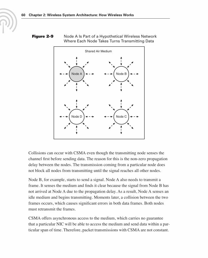
If Node A has data to send, Node A first checks—senses—if any other nodes are transmitting data. (See Figure 2-9.) If the medium is clear—no transmission is heard—Node A will transmit one frame of data. If Node A senses transmissions from another node, Node A holds off transmitting and waits a period of time before sensing the channel again. The sensing operation continues until the node sends the data frame.
1119fmF.book Page 59 Wednesday, July 7, 2004 7:39 AM
60 Chapter 2: Wireless System Architecture: How Wireless Works
Figure 2-9 Node A Is Part of a Hypothetical Wireless Network Where Each Node Takes Turns Transmitting Data
Collisions can occur with CSMA even though the transmitting node senses the channel first before sending data. The reason for this is the non-zero propagation delay between the nodes. The transmission coming from a particular node does not block all nodes from transmitting until the signal reaches all other nodes.
Node B, for example, starts to send a signal. Node A also needs to transmit a frame. It senses the medium and finds it clear because the signal from Node B has not arrived at Node A due to the propagation delay. As a result, Node A senses an idle medium and begins transmitting. Moments later, a collision between the two frames occurs, which causes significant errors in both data frames. Both nodes must retransmit the frames.
CSMA offers asynchronous access to the medium, which carries no guarantee that a particular NIC will be able to access the medium and send data within a par-ticular span of time. Therefore, packet transmissions with CSMA are not constant.
Shared Air Medium
Node A
Node D
Node B
Node C
1119fmF.book Page 60 Wednesday, July 7, 2004 7:39 AM

Flow of Information Through a Wireless Network 61
This poses a problem for the transmission of real-time information, such as voice and video, because the network might not deliver pieces of information regularly enough to meet quality needs. In this case, QoS functions and higher throughput are necessary to improve performance.
Error Control
Information signals might encounter bit errors when propagating through the air medium. Noise and interference within the area of the wireless network causes these errors. As a result, wireless NICs implement error control mechanisms that detect and correct bit errors.
Noise from the sun’s radiation and man-made devices cause damage to wireless information signals and is always present. The noise floor, however, is often low enough so that receivers are capable of distinguishing the information signal from the noise. At longer ranges, however, attenuation might reduce the information signal to a level that falls below the noise floor, and bit errors begin to occur.
The noise causing altered bits within wireless networks is usually Gaussian, or impulse noise. Theoretically, the amplitude of Gaussian noise is uniform across the frequency spectrum, and it normally triggers random errors that are indepen-dent of each other. Impulse noise, the most disastrous, is characterized by long quiet intervals of time followed by high-amplitude bursts. This noise results from natural causes— such as lightning— as well as man-made causes. Impulse noise is responsible for most errors in digital communication systems and generally provokes errors to occur dependently in groups. This distortion is referred to as burst errors.
Error control techniques highly reduce the number of transmission errors. Bit errors might still occur while data frames travel through the air medium, but error control mechanisms correct the errors. As a result, the transmission of information through medium appears error-free to higher-layer protocols and the users.
The two primary types of error control are automatic repeat-request (ARQ) and forward error correction (FEC). With ARQ, which operates at the data link layer, the receiving wireless NIC detects errors and uses a feedback path to the sending wireless NIC for requesting the retransmission of frames having bit errors. There
1119fmF.book Page 61 Wednesday, July 7, 2004 7:39 AM

62 Chapter 2: Wireless System Architecture: How Wireless Works
are two main events that must occur to correct errors with ARQ. First, a received frame must be checked at the receiver for possible errors, and then the sender must be notified to retransmit the frames received in error. In some protocols, such as 802.11, the receiver sends an acknowledgement to the sender if the received frame has no errors. The absence of an acknowledgement indicates to the sender to retransmit the frame.
Two approaches for retransmitting unsatisfactory blocks of data exist:
■ Stop-and-wait ARQ
■ Continuous ARQ
Stop-and-Wait ARQ
In the stop-and-wait method of transmission, the sending NIC transmits a block of data, then stops and waits for an acknowledgment from the receiving NIC on whether a particular frame was acceptable or not. If the sending side receives a negative acknowledgment, the previous frame will be sent again. The sending NIC will send the next frame after it receives a positive acknowledgment from the receiving NIC. The IEEE 802.11 standard specifies this form of error control.
One advantage of stop-and-wait ARQ is it does not require much memory space at the sending or receiving NIC. The outstanding transmitted frame needs only to be stored at the sender (in case of retransmission). On the other hand, stop-and-wait ARQ becomes inefficient as the propagation delay between the source and desti-nation becomes large. For example, data sent on satellite links normally experi-ence a round-trip delay of several hundred milliseconds; therefore, long block lengths are necessary to maintain a reasonably effective data rate. The trouble is that with longer data blocks the probability of an error occurring in a particular block is greater. Therefore, retransmission will occur often, and the resulting throughput will be lower.
Continuous ARQ
One way of improving the throughput on longer links is to use the continuous ARQ method. With this type of ARQ, the transmitter sends data blocks continu-ously until the receiving NIC detects an error. The sending NIC is usually capable
1119fmF.book Page 62 Wednesday, July 7, 2004 7:39 AM

Flow of Information Through a Wireless Network 63
of transmitting a certain number of frames and keeps a log of which frames have been sent. Once the receiving side detects a bad block, it will send a signal back to the sending NIC requesting that the bad frame be sent over again. When the receiver gets the signal to retransmit a certain frame, several subsequent frames might have already been sent because of propagation delays between the sender and receiver.
The sending NIC can retransmit frames with continuous ARQ in several ways. One method is for the source to retrieve the erred frame from the transmit memory and send the bad frame as well as the subsequent frames. This is called the go-back-n technique, and it can be more effective than the stop-and-wait ARQ because it makes better use of the channel bandwidth. One problem though is when n—the number of frames the transmitter sent after the erred frame plus one—becomes large, the method becomes inefficient. This is because the retrans-mission of just one frame means that a large number of good frames will also be resent, which decreases throughput.
The go-back-n technique is useful in applications where the receiver has little memory space because all that is needed is a receiver window size of one (ability to store one frame), assuming frames do not need to be delivered in order. When the receiving NIC rejects an erred frame —sends a negative acknowledgment—it does not need to store any subsequent frames for possible reordering while it is waiting for the retransmission. It need not wait because all subsequent frames will also be resent.
An alternative to the continuous go-back-n technique is a method that selectively retransmits only the erred frame and resumes normal transmission at the point just before getting the notification of a bad block of data. This is the selective repeat approach. Selective repeat is obviously better than continuous go-back-n in terms of throughput because the sending NIC only transmits the erred data block; how-ever, the receiver must be capable of storing a number of data frames if they are to be processed in order. The receiver needs to buffer data that have been received after an erred frame was requested for retransmission as only the damaged frame will be resent.
1119fmF.book Page 63 Wednesday, July 7, 2004 7:39 AM

64 Chapter 2: Wireless System Architecture: How Wireless Works
All ARQ types depend on the detection of errors and the retransmission of the faulty data. Overall, ARQ is best for the correction of burst errors because this type of distortion normally occurs in a small percentage of frames, and does not invoke many retransmissions. Because of the feedback inherent in ARQ protocols, half-duplex or full-duplex lines must be in use since ARQ communication occurs in both directions. If only simplex links are available, it is impossible to use the ARQ technique because the receiver would not be able to notify the sending NIC of bad data blocks.
As an alternative to ARQ, FEC automatically corrects as many errors as it can within the physical layer at the receiving NIC without referring to the sending NIC. This is possible because the sending NIC includes enough redundant bits in case some are lost because of errors. This makes FEC well suited for simplex communications links, and cases where a return path to the sending NIC is not feasible.
For example, consider sending data wirelessly to control a space probe orbiting Pluto. By the time the sending NIC receives a negative acknowledgement from the probe and the corresponding retransmission of data reaches the probe, the probe would likely crash because of the significant propagation delay. Most wire-less networks exist on Earth, but propagation delays can still be significant enough to warrant the use of FEC.
Despite the ability of FEC to correct errors without referring to the sending NIC, ARQ is still the most common method of error control. This is mainly because errors usually occur in clusters because of impulse noise. This places a require-ment to correct large numbers of errors, which FEC typically cannot accomplish without excessive amounts of redundancy.
Many communications systems, however, are utilizing a combination of both ARQ and FEC. In this case, the physical layer devices attempt to correct a small number of errors to avoid a retransmission. If FEC corrects all the errors, the ARQ mechanism will not need to resend the data frame. If there are a large number of errors, ARQ steps in and the sender will resend the frame.
1119fmF.book Page 64 Wednesday, July 7, 2004 7:39 AM

Flow of Information Through a Wireless Network 65
Transferring Wireless Data Signals
The air medium does not offer any active components to the wireless network. Several passive elements impact the appearance and effectiveness of the wireless information signals. While propagating through the medium, for example, the sig-nals will encounter attenuation from solid objects and weather, as well as loss because of the distance between the sending and receiving NIC. In addition, the signals propagating through the medium can encounter interference, multi-path propagation, and other elements that can impair the signal. Refer to Chapter 3 for more details on these impairments.
Connecting with the Wireless Network Infrastructure
The base station, such as an access point, includes both a wireless and wired NIC, as well as software that interfaces the two networks. When a wireless user com-municates with another wireless user, the base station might simply resend the data frame received from one user so that the other user is able to receive it. In this case, the base station is acting as a repeater. Alternatively, the base station might forward the data to the wired side of the base station if the destination is located somewhere on the wired side of the network.
Upon receiving a data frame, the wireless NIC within the base station converts the analog radio wave or light signal into a digital signal and performs error detection to ensure that the resulting data frame does not have any bit errors. The error con-trol mechanism will cause the sending wireless NIC to retransmit the data frame if errors are present. After taking care of erred frames, the wireless NIC within the base station will either resend the frame or forward the frame to the wired side of the base station.
The wired NIC generally implements Ethernet, which interfaces directly with enterprise systems. The base station usually connects the wireless and wired net-works at the physical layer and data link layer. Some base stations also include routing, which is a network layer function.
1119fmF.book Page 65 Wednesday, July 7, 2004 7:39 AM

66 Chapter 2: Wireless System Architecture: How Wireless Works
When traversing wire, the information signal remains in digital form, but different types of systems might convert the digital signal to a form suitable for transmis-sion over the particular medium in use. The signal might undergo conversion to an analog form again if transmission over another wireless link, such as satellite, is necessary to reach the destination.
Chapter SummaryWireless networks include components that make mobile and portable application possible. Users are end points of the wireless network and utilize computer devices designed for a particular application. Wireless NICs and base stations are key components that communicate over the air medium. To provide roaming throughout a facility or city, a distribution system such as Ethernet interconnects base stations and interfaces users to servers and applications located on the wired network.
The seven-layer OSI reference model depicts functions necessary for a network, but wireless networks implement only functions defined by the bottom two layers—the physical and data link layer. These functions include medium access, error control, and formation of radio and light signals for propagation through the medium. When deploying wireless networks, however, it’s important to ensure that protocols operating at higher layers have features that counter impairments found in wireless networks.
1119fmF.book Page 66 Wednesday, July 7, 2004 7:39 AM

Chapter Review Questions 67
Chapter Review QuestionsYou can find the answers to the following questions in Appendix A, “Answers to Chapter Review Questions.”
1. Which wireless NIC form factors are best for small wireless computer devices?
2. What are examples of elements that impair the propagation of wireless com-munications signals through the air medium?
3. What is the primary purpose of a base station?
4. What are common features of wireless middleware?
5. On what layers of the OSI reference model do wireless networks operate?
6. How is throughput different from data rate?
7. True or false: A computer device stores data in analog form.
8. A wireless NIC must convert the information into what type of signal before transmission through the air medium?
9. Which medium access protocol is common with wireless networks?
10. Explain how the ARQ form of error control works.
1119fmF.book Page 67 Wednesday, July 7, 2004 7:39 AM


![Wireless Architecture[1]](https://static.fdocuments.in/doc/165x107/577ce4561a28abf1038e1f1b/wireless-architecture1.jpg)


