CHAPTER 4 HEAT TREATMENT 4.1...
17
27 CHAPTER 4 HEAT TREATMENT 4.1 INTRODUCTION Pistons are subjected to different type of heat treatments in order to promote better bonding characterisation. The bonding nature is observed through Scanning Electron Microscope (SEM) and the phases present at the bonding region are observed through X-ray Diffraction (XRD) study. The shear strength test comparison is done on the heat treated and as cast pistons. 4.2 HEAT TREATMENT Heat treatment plays vital role to increase the bond strength and hardness of the material. It is often associated with increasing the strength of material, but it can also be used to change certain manufacturability objectives. It also enhances the desirable properties of the component without changing the shape. It leads to increase the performance of the component. 4.2.1 Specimen Preparation Typical macrograph of a piston with the cast iron insert is presented in Figure 4.1. The as cast piston is sectioned into different segments to study its characteristics. Typical specimens are presented in Figure 4.2. Preliminary trials are conducted on these specimens to arrive at heat treatment schedules for the piston.
Transcript of CHAPTER 4 HEAT TREATMENT 4.1...

27
CHAPTER 4
HEAT TREATMENT
4.1 INTRODUCTION
Pistons are subjected to different type of heat treatments in order
to promote better bonding characterisation. The bonding nature is observed
through Scanning Electron Microscope (SEM) and the phases present at the
bonding region are observed through X-ray Diffraction (XRD) study. The
shear strength test comparison is done on the heat treated and as cast
pistons.
4.2 HEAT TREATMENT
Heat treatment plays vital role to increase the bond strength and
hardness of the material. It is often associated with increasing the strength
of material, but it can also be used to change certain manufacturability
objectives. It also enhances the desirable properties of the component
without changing the shape. It leads to increase the performance of the
component.
4.2.1 Specimen Preparation
Typical macrograph of a piston with the cast iron insert is
presented in Figure 4.1. The as cast piston is sectioned into different
segments to study its characteristics. Typical specimens are presented in
Figure 4.2. Preliminary trials are conducted on these specimens to arrive at
heat treatment schedules for the piston.

28
Figure 4.1 Piston with cast iron insert
Figure 4.2 Typical specimen of piston
Al Al
CI
CI
Al

29
4.2.2 Heat Treatment for Pistons
The pistons are subjected to heat treatments at different
temperatures with tempering and without tempering. Based on the
preliminary studies, it is subjected to the following heat treatments:
As cast piston without any heat treatment.
Piston heat treated at 503 K for 7 hours and quenched in air.
Piston heat treated at 773 K for 9 hours and quenched in
water then tempered at 473 K for 2 hours.
4.2.3 METALLURGICAL EXAMINATIONS
4.2.3.1 Scanning Electron Microscope
The bonded region of aluminum and cast iron is observed
through SEM. To have better understanding, treated and untreated pistons
are subjected to the micro structural studies. Metallurgical characteristics of
as cast and heat treated pistons are studied through scanning electron
microscope. The changes of phases present at aluminum cast iron bonding
region (Al-CI) are analyzed through XRD test. Specimens are cut from the
heat treated and un treated pistons. Specimens are polished and etched with
Nital (10%) as an etching agent. Typical microstructures of the untreated
(as cast) pistons are presented in Figures 4.3 and 4.4. At lower
magnification, no remarkable discontinuity is observed, however, at higher
magnification, de bonding zones are observed at the interface. Cracks are
also observed at the nearby zone of bonding. This lack of integrity naturally
results in reduced strength and associated poor qualities.

30
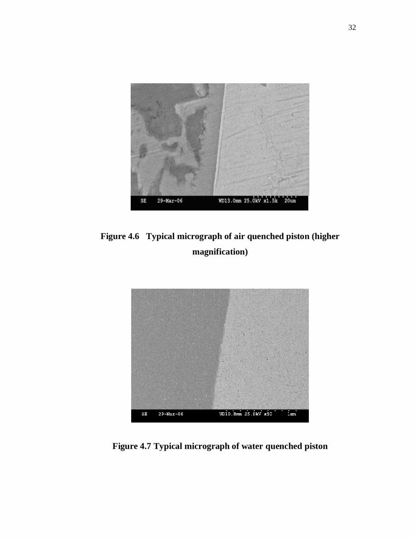
Microstructures of the air quenched piston are presented in the
Figures 4.5 and 4.6. In this case, clear bond interface is observed even at
higher magnification (x1500). Better integrity of aluminum and cast iron is
observed. Presence of cracks at the bonding interface is minimized. From
the Microstructure, it can be clearly seen that aluminum and cast iron are
perfectly bonded. No remarkable voids and cracks are observed at the
interface. Microstructure at higher magnification (x1500) reveals the same.
White layer, observed at the bonding zone reveals the diffusion of
aluminum through cast iron part. This kind of perfect registry improved the
strength.
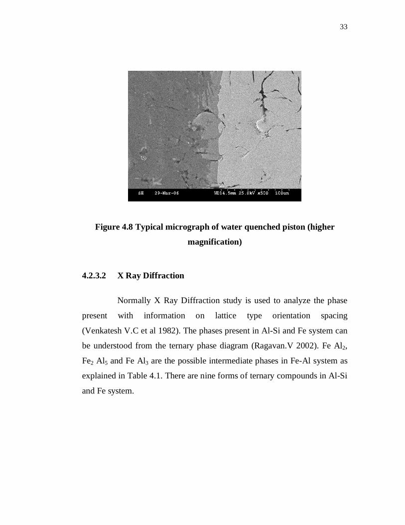
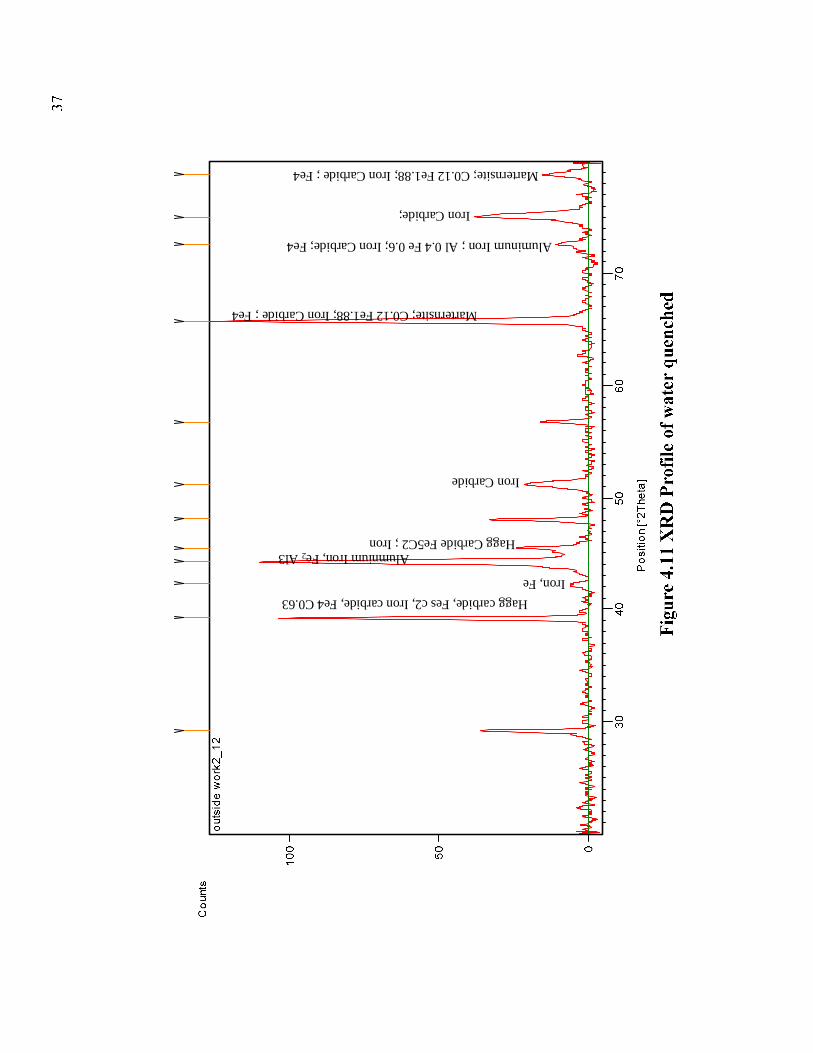
SEM micrographs of water quenched piston are presented in
Figures 4.7 and 4.8. From the figures, it can be understood that the bonding
interface is continuous which is comparable with the air quenched
specimen. No debonding zones are observed at the interface. Cracks are
observed at either side of the bonding zone. More number of cracks are
observed at the aluminum side.

31
Figure 4.3 Typical micrograph of as cast piston
Figure 4.4 Typical micrograph of as cast piston (higher magnification)
Figure 4.5 Typical micrograph of as air quenched piston
32
Figure 4.6 Typical micrograph of air quenched piston (higher
magnification)
Figure 4.7 Typical micrograph of water quenched piston
33
Figure 4.8 Typical micrograph of water quenched piston (higher
magnification)
4.2.3.2 X Ray Diffraction
Normally X Ray Diffraction study is used to analyze the phase
present with information on lattice type orientation spacing
(Venkatesh V.C et al 1982). The phases present in Al-Si and Fe system can
be understood from the ternary phase diagram (Ragavan.V 2002). Fe Al2,
Fe2 Al5 and Fe Al3 are the possible intermediate phases in Fe-Al system as
explained in Table 4.1. There are nine forms of ternary compounds in Al-Si
and Fe system.

34
Table 4.1 Al-Fe-Si crystal structure [54]
Phase% Composition
Al Fe SiAl2Fe3Si3 25.0 37.5 37.5Al2FeSi 50.0 25.0 25.0
Al2.7FeSi2.3 45.0 16.7 38.3Al15Fe6Si5 57.7 23.1 19.2Al4.5FeSi 69.2 15.4 15.4
Al63.5Fe20.5Si16 93.5 20.5 16.0Al6Fe4Si6 37.5 25.0 37.5Al2Fe3Si4 22.2 33.3 44.4Al4Fe1.7Si 59.7 25.4 14.9
Specimens of treated and untreated are subjected to XRD studies
in order to understand the typical changes in phases. These changes affect
the performance of pistons. Figure 4.9 gives the XRD profile of as cast Al-
CI piston. Peaks of iron, iron carbide, aluminum and its intermetallic
compounds are observed. However, in this case, presence of very hard
phases is not noticed.
XRD profile of air quenched specimen is presented in Figure
4.10. No remarkable changes are observed in the air quenched specimen
when compared with the intensity of the peaks of untreated specimen.
Figure 4.11 shows the XRD profile of the water quenched
specimen. Compared with previous specimens (as cast and air quenched)
there are remarkable changes in the profile. Presence of hard phases
(martensite) with increased intensity is observed. Presence of such hard
phase increases the hardness of the zone.

Aluminum; Al
Fe2 Al3 Si3Aluminum; Al Hagg Carbide
Hagg Carbide
Hagg Carbide
Aluminum; Al
Hagg Carbide
Aluminum; Al

Hagg carbide, Fe5C2
Fe2Al3 Hagg carbide, Fe5 C2
Aluminum Iron Carcide; Al Fe3C
Hagg carbide, Fe5 C2
Hagg carbide, Fe5C2
Hagg carbide, Fe5C2
Aluminum Iron Carcide; Al Fe3C
Hagg carbide, Fe5C2
Hagg carbide, Fes c2, Iron carbide, Fe4 C0.63
Alumnium Iron, Fe2Al3
Iron, Fe
Hagg Carbide Fe5C2; Iron
Iron Carbide
Marternsite; C0.12 Fe1.88; Iron Carbide ; Fe4
Aluminum Iron ; Al 0.4 Fe 0.6; Iron Carbide; Fe4
Iron Carbide;
Marternsite; C0.12 Fe1.88; Iron Carbide ; Fe4

38
4.3 HARDNESS SURVEY
The polished specimens of Al-CI (treated and untreated) are
studied through hardness survey. Hardness data was taken using Brinell
hardness tester at five different locations on the specimen at either side. The
average data was calculated. Equivalent hardness in Vickers scale is
reported.
The hardness variation for as cast, air quenched and water
quenched piston of aluminum and cast iron sides are presented with the
equivalent Vickers hardness (HV) value in Figures 4.12 and 4.13
respectively.
Figure 4.12 Hardness chart of Aluminum
Figure 4.13 Hardness chart of Cast iron
Hardness chart
75
90
105
120
135
150
1 2 3
Specimen
Al
As cast Air quenched Water quenched
Hardness chart
130
140
150
160
1 2 3
Specimen
CI
As cast Air quenched Water quenched

39
Compared to as cast piston, the hardness of aluminum and cast iron are
observed to be increasing due to the heat treatments such as air and water
quenching. Precipitation strengthening and possible phase changes have
occurred in the treated pistons. This might be the reason for the
enhancement of hardness. Compared to air quenched pistons, water
quenched ones exhibit higher hardness on either side.
4.4 STRENGTH TEST
The bimetallic piston has to be machined to get its nearest net
shape. There is a possibility of separation of cast iron insert from aluminum
body during machining. This is due to the shear stress, which occurs during
machining of such bimetallic pistons. Hence, interfacial bond between
aluminum and cast iron should not break/disintegrate during machining.
The shear strength estimation gives an idea of machining capacity of the
pistons. Shear strength testing or push out test is normally done to
determine the strength between the reinforcement and base alloy. Typical
study was also carried out by Durrant et al (1996) for squeeze cast
aluminum with mild steel insert. Shear/push out test is done to estimate the
bonding strength. Fuel Instruments and Controls Ltd, make Universal
Testing Machine (UTM) is used to determine the shear strength.
A round pin is used to apply load at the Al-CI interface. The load
and displacement data are recorded from UTM. Typical positions of round
pin prior and after the application of load are presented in Figure 4.14 and
Figure 4.15 respectively.

40
Figure 4.14 Typical load sketch before shearing
Figure 4.15 Typical load sketch after shearing
Complete piston is supported and the load is applied to evaluate
the strength related aspect. Typical load test on piston is done, and is
presented in Figure 4.16.The crack portion due to shear is also shown in
Figure 4.17.

41
Figure 4.16 Typical application of load on piston
Figure 4.17 Cracked piston after strength test

42
Typical behavior of air quenched piston, when subjected to shear
strength is presented in Figure 4.18.
Figure 4.18 Typical strength test result of air quenched piston
The typical data of breaking load, ultimate load and elongation
are presented in Table 4.2.
Table 4.2 Typical strength test result
Parameter Result
Peak load 45.5 KN
Displacement at Max force 2.9 mm
Breaking Load 39.050 KN
Maximum Displacement 3 mm
Similarly, strength test also conducted for heat treated and untreated
pistons. Typical shear strength (load at which bond breaks) data of the
treated and untreated pistons are presented in Table 4.3.

43
Table 4.3 Strength result of different pistons
Specimen As cast Air quenched Water quenched
Strength (KN) 32 39 44
From the Table 4.3, it can be observed that the as cast piston (without any
heat treatment) exhibits the least strength among the tested specimens. It is
due to the poor bonding of aluminum and cast iron insert. Air quenched
specimen exhibits better strength when compared to untreated specimens.
However, water quenched specimen exhibit the highest strength among all.
4.5 SUMMARY
This chapter emphasizes the characteristics of various heat
treated and as cast pistons. Bonding nature is analyzed through SEM study.
XRD study reveals the phases at the interface. Hardness and shear strength
data revealed the mechanical characteristics of the pistons. Performance of
treated and as cast pistons are compared and shown in Table 4.4.
Table 4.4 Comparison of different treated pistons
Properties UntreatedTreated
(Air quenched)
Treated
(Water quenched)
XRD No hard phases Hard phases found Hard phases found
SEM Poor bonding Good bonding Cracks at either
side
Hardness Least High Very high
Shear Strength 145 Mpa 177 Mpa 220 Mpa