
Chapter 4 Commentary STRUCTURAL DESIGN CRITERA
24
35 Chapter 4 Commentary STRUCTURAL DESIGN CRITERA 4.1 GENERAL 4.1.2 References. ASCE 7 is referenced for the combination of earthquake loadings with other loads as well as for the computation of other loads; it is not referenced for the computation of earthquake loads. 4.2 GENERAL REQUIREMENTS 4.2.1 Design basis. Structural design for acceptable seismic resistance includes: 1. The selection of gravity- and seismic-force-resisting systems that are appropriate to the anticipated intensity of ground shaking; 2. Layout of these systems such that they provide a continuous, regular, and redundant load path capable of ensuring that the structures act as integral units in responding to ground shaking; and 3. Proportioning the various members and connections such that adequate lateral and vertical strength and stiffness is present to limit damage in a design earthquake to acceptable levels. In the Provisions, the proportioning of structural elements (sizing of individual members, connections, and supports) is typically based on the distribution of internal forces computed based on linear elastic response spectrum analyses using response spectra that are representative of, but substantially reduced from the anticipated design ground motions. As a result, under the severe levels of ground shaking anticipated for many regions of the nation, the internal forces and deformations produced in most structures will substantially exceed the point at which elements of the structures start to yield or buckle and behave in an inelastic manner. This approach can be taken because historical precedent and the observation of the behavior of structures that have been subjected to earthquakes in the past demonstrates that if suitable structural systems are selected and structures are detailed with appropriate levels of ductility, regularity, and continuity, it is possible to perform an elastic design of structures for reduced forces and still achieve acceptable performance. Therefore, these procedures adopt the approach of proportioning structures such that under prescribed design lateral forces that are significantly reduced, by the response modification coefficient R, from those that would actually be produced by a design earthquake they will not deform beyond a point of significant yield. The elastic deformations calculated under these reduced design forces are then amplified, by the deflection amplification factor C d to estimate the expected deformations likely to be experienced in response to the design ground motion. (Use of the deflection amplification factor is specified in Sec. 5.2.6.1.) Considering the intended structural performance and acceptable deformation levels, Sec. 4.5.1 prescribes the story drift limits for the expected (amplified) deformations. These procedures differ from those in earlier codes and design provisions wherein the drift limits were treated as a serviceability check. The term “significant yield” is not the point where first yield occurs in any member but, rather, is defined as that level causing complete plastification of at least the most critical region of the structure (such as formation of a first plastic hinge in the structure). A structural steel frame comprising compact members is assumed to reach this point when a “plastic hinge” develops in the most highly stressed member of the structure. A concrete frame reaches significant yield when at least one of the sections of its most highly stressed component reaches its strength as set forth in Chapter 9. These requirements contemplate that the design includes a seismic-force-resisting system with redundant characteristics wherein significant structural overstrength above the level of significant yield can be obtained by plastification at other points in the structure prior to the formation of a complete mechanism. For example, Figure C4.2-1 shows the
Transcript of Chapter 4 Commentary STRUCTURAL DESIGN CRITERA

35
Chapter 4 Commentary
STRUCTURAL DESIGN CRITERA
4.1 GENERAL 4.1.2 References. ASCE 7 is referenced for the combination of earthquake loadings with other loads as well as for the computation of other loads; it is not referenced for the computation of earthquake loads.
4.2 GENERAL REQUIREMENTS
4.2.1 Design basis. Structural design for acceptable seismic resistance includes:
1. The selection of gravity- and seismic-force-resisting systems that are appropriate to the anticipated intensity of ground shaking;
2. Layout of these systems such that they provide a continuous, regular, and redundant load path capable of ensuring that the structures act as integral units in responding to ground shaking; and
3. Proportioning the various members and connections such that adequate lateral and vertical strength and stiffness is present to limit damage in a design earthquake to acceptable levels.
In the Provisions, the proportioning of structural elements (sizing of individual members, connections, and supports) is typically based on the distribution of internal forces computed based on linear elastic response spectrum analyses using response spectra that are representative of, but substantially reduced from the anticipated design ground motions. As a result, under the severe levels of ground shaking anticipated for many regions of the nation, the internal forces and deformations produced in most structures will substantially exceed the point at which elements of the structures start to yield or buckle and behave in an inelastic manner. This approach can be taken because historical precedent and the observation of the behavior of structures that have been subjected to earthquakes in the past demonstrates that if suitable structural systems are selected and structures are detailed with appropriate levels of ductility, regularity, and continuity, it is possible to perform an elastic design of structures for reduced forces and still achieve acceptable performance. Therefore, these procedures adopt the approach of proportioning structures such that under prescribed design lateral forces that are significantly reduced, by the response modification coefficient R, from those that would actually be produced by a design earthquake they will not deform beyond a point of significant yield. The elastic deformations calculated under these reduced design forces are then amplified, by the deflection amplification factor Cd to estimate the expected deformations likely to be experienced in response to the design ground motion. (Use of the deflection amplification factor is specified in Sec. 5.2.6.1.) Considering the intended structural performance and acceptable deformation levels, Sec. 4.5.1 prescribes the story drift limits for the expected (amplified) deformations. These procedures differ from those in earlier codes and design provisions wherein the drift limits were treated as a serviceability check.
The term “significant yield” is not the point where first yield occurs in any member but, rather, is defined as that level causing complete plastification of at least the most critical region of the structure (such as formation of a first plastic hinge in the structure). A structural steel frame comprising compact members is assumed to reach this point when a “plastic hinge” develops in the most highly stressed member of the structure. A concrete frame reaches significant yield when at least one of the sections of its most highly stressed component reaches its strength as set forth in Chapter 9. These requirements contemplate that the design includes a seismic-force-resisting system with redundant characteristics wherein significant structural overstrength above the level of significant yield can be obtained by plastification at other points in the structure prior to the formation of a complete mechanism. For example, Figure C4.2-1 shows the

2003 Commentary, Chapter 4
36
lateral load-deflection curve for a typical structure. Significant yield is the level where plastification occurs
at the most heavily loaded element in the structure, shown as the lowest yield hinge on the load-deflection diagram. With increased loading, causing the formation of additional plastic hinges, the capacity increases (following the solid curve ) until a maximum is reached. The overstrength capacity obtained by this continued inelastic action provides the reserve strength necessary for the structure to resist the extreme motions of the actual seismic forces that may be generated by the design ground motion.
It should be noted that the structural overstrength described above results from the development of sequential plastic hinging in a properly designed, redundant structure. Several other sources will further increase structural overstrength. First, material overstrength (that is, actual material strengths higher than the nominal material strengths specified in the design) may increase the structural overstrength significantly. For example, a recent survey shows that the mean yield strength of A36 steel is about 30 to 40 percent higher than the minimum specified strength, which is used in design calculations. Second, member design strengths usually incorporate a strength reduction (or resistance) factor, φ, to ensure a low probability of failure under
design loading. Third, designers themselves introduce additional overstrength by selecting sections or specifying reinforcing patterns that exceed those required by the computations. Similar situations occur when minimum requirements of the Provisions, for example, minimum reinforcement ratios, control the design. Finally, the design of many flexible structural systems, such as moment resisting frames, are often controlled by the drift rather than strength limitations of the Provisions, with sections selected to control lateral deformations rather than provide the specified strength. The results is that structures typically have a much higher lateral resistance than specified as a minimum by the Provisions and first actual significant yielding of structures may occur at lateral load levels that are 30 to 100 percent higher than the prescribed design seismic forces. If provided with adequate ductile detailing, redundancy, and regularity, full yielding of structures may occur at load levels that are two to four times the prescribed design force levels.
Figure C4.2-1 indicates the significance of design parameters contained in the Provisions including the response modification coefficient, R, the deflection amplification factor, Cd, and the structural overstrength coefficient Ω0. The values of the response modification coefficient, R, structural overstrength coefficient, Ω0, and the deflection amplification factor, Cd, provided in Table 4.3-1, as well as the criteria for story drift, including P-delta effects, have been established considering the characteristics of typical properly designed structures. If excessive “optimization” of a structural design is performed, with lateral resistance provided by only a few elements, the successive yield hinge behavior depicted in Figure C4.2-1 will not be able to form and the values of the design parameters contained in the Provisions may not be adequate to provide the intended seismic performance.
The response modification coefficient, R, essentially represents the ratio of the forces that would develop under the specified ground motion if the structure had an entirely linearly elastic response to the prescribed design forces (see Figure C4.2-1). The structure is to be designed so that the level of significant yield exceeds the prescribed design force. The ratio R, expressed by the equation:
Lateral Deformation (Drift), D
succesiveyield hinges
Elastic response of structure
VE
DE
Design force levelVS
Fully yielded strength
DS
Design driftCd
VY
D
V
Figure C4.2-1 Inelastic force-deformation curve.
Structural Design Criteria
37
E
S
VRV
= (C4.2-1)
is always larger then 1.0; thus, all structures are designed for forces smaller than those the design ground motion would produce in a structure with completely linear-elastic response. This reduction is possible for a number of reasons. As the structure begins to yield and deform inelastically, the effective period of response of the structure tends to lengthen, which for many structures, results in a reduction in strength demand. Furthermore, the inelastic action results in a significant amount of energy dissipation, also known as hysteretic damping, in addition to the viscous damping. The combined effect, which is also known as the ductility reduction, explains why a properly designed structure with a fully yielded strength (Vy in Figure C4.2-1) that is significantly lower than the elastic seismic force demand (VE in Figure C4.2-1) can be capable of providing satisfactory performance under the design ground motion excitations. Defining a system ductility reduction factor Rd as the ratio between VE and VY (Newmark and Hall, 1981):
Ed
Y
VRV
= (C4.2-2)
then it is clear from Figure C4.2-1 that the response modification coefficient, R, is the product of the ductility reduction factor and structural overstrength factor (Uang, 1991):
0dR R= Ω (C4.2-3)
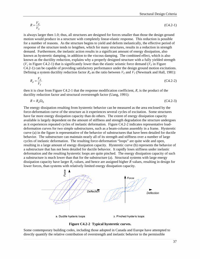
The energy dissipation resulting from hysteretic behavior can be measured as the area enclosed by the force-deformation curve of the structure as it experiences several cycles of excitation. Some structures have far more energy dissipation capacity than do others. The extent of energy dissipation capacity available is largely dependent on the amount of stiffness and strength degradation the structure undergoes as it experiences repeated cycles of inelastic deformation. Figure C4.2-2 indicates representative load-deformation curves for two simple substructures, such as a beam-column assembly in a frame. Hysteretic curve (a) in the figure is representative of the behavior of substructures that have been detailed for ductile behavior. The substructure can maintain nearly all of its strength and stiffness over a number of large cycles of inelastic deformation. The resulting force-deformation “loops” are quite wide and open, resulting in a large amount of energy dissipation capacity. Hysteretic curve (b) represents the behavior of a substructure that has not been detailed for ductile behavior. It rapidly loses stiffness under inelastic deformation and the resulting hysteretic loops are quite pinched. The energy dissipation capacity of such a substructure is much lower than that for the substructure (a). Structural systems with large energy dissipation capacity have larger Rd values, and hence are assigned higher R values, resulting in design for lower forces, than systems with relatively limited energy dissipation capacity.
Figure C4.2-2 Typical hysteretic curves.
Some contemporary building codes, including those adopted in Canada and Europe have attempted to directly quantify the relative contribution of overstrength and inelastic behavior to the permissible

2003 Commentary, Chapter 4
38
reduction in design strength. Recently, the Structural Engineers Association of California proposed such an approach for incorporation into the 1997 Uniform Building Code. That proposal incorporated two R factor components, termed R0 and Rd, to represent the reduction due to structural overstrength and inelastic behavior, respectively. The design forces are then determined by forming a composite R, equal to the product of the two components (see Eq. C4.2-3). A similar approach was considered for adoption into the 1997 NEHRP Provisions. However, this approach was not taken for several reasons. While it was acknowledged that both structural overstrength and inelastic behavior are important contributors to the R coefficients and that they can be quantified for individual structures, it was felt that there was insufficient research available at the current time to support implementation in the Provisions. In addition, there was concern that there can be significant variation between structures in the relative contribution of overstrength and inelastic behavior and that, therefore, this would prevent accurate quantification on a system-by-system basis. Finally, it was felt that this would introduce additional complexity into the Provisions. While it was decided not to introduce the split R value concept into the Provisions in the 1997 update cycle, this should be considered in the future as additional research on the inelastic behavior of structures becomes available and as the sophistication of design offices improves to the point that quantification of structural overstrength can be done as a routine part of the design process. As a first step in this direction, however, the factor Ω0 was added to Table 4.3-1, to replace the previous 2R/5 factor used for evaluation of brittle structural behavior modes in previous editions of the Provisions.
The R values, contained in the current Provisions, are largely based on engineering judgment of the performance of the various materials and systems in past earthquakes. The values of R must be chosen and used with careful judgment. For example, lower values must be used for structures possessing a low degree of redundancy wherein all the plastic hinges required for the formation of a mechanism may be formed essentially simultaneously and at a force level close to the specified design strength. This situation can result in considerably more detrimental P-delta effects. Since it is difficult for individual designers to judge the extent to which R factors should be adjusted based on the inherent redundancy of their designs, a coefficient, ρ, which is calculated based on the amount of the total lateral force resisted by any individual element, is found in Provisions in Sec. 4.3.3. Additional discussion of this issue is contained in that section.
In a departure from previous editions of the Provisions, the 1997 edition introduced an importance factor I into the base shear equation, which factor varies for different types of occupancies. This importance factor has the effect of adjusting the permissible response modification factor, R, based on the desired seismic performance for the structure. It recognizes that greater levels of inelastic behavior, correspond to increased structural damage. Thus, introducing the importance factor, I, allows for a reduction of the R value to an effective value R/I as a partial control on the amount of damage experienced by the structure under a design earthquake. Strength alone is not sufficient to obtain enhanced seismic performance. Therefore, the improved performance characteristics desired for more critical occupancies are also obtained through application of the design and detailing requirements set forth in Sec. 4.6 for each Seismic Design Category and the more stringent drift limits in Table 4.5-1. These factors, in addition to strength, are extremely important to obtaining the seismic performance desired for buildings in some Seismic Use Groups.
Sec. 4.2.1 in effect calls for the seismic design to be complete and in accordance with the principles of structural mechanics. The loads must be transferred rationally from their point of origin to the final points of resistance. This should be obvious but it often is overlooked by those inexperienced in earthquake engineering.
Design consideration should be given to potentially adverse effects where there is a lack of redundancy. Because of the many unknowns and uncertainties in the magnitude and characteristics of earthquake loading, in the materials and systems of construction for resisting earthquake loadings, and in the methods of analysis, good earthquake engineering practice has been to provide as much redundancy as possible in the seismic-force-resisting system of buildings.

Structural Design Criteria
39
Redundancy plays an important role in determining the ability of the building to resist earthquake forces. In a structural system without redundant components, every component must remain operative to preserve the integrity of the building structure. On the other hand, in a highly redundant system, one or more redundant components may fail and still leave a structural system that retains its integrity and can continue to resist lateral forces, albeit with diminished effectiveness.
Redundancy often is accomplished by making all joints of the vertical load-carrying frame moment resisting and incorporating them into the seismic-force-resisting system. These multiple points of resistance can prevent a catastrophic collapse due to distress or failure of a member or joint. (The overstrength characteristics of this type of frame were discussed earlier in this section.)
The designer should be particularly aware of the proper selection of R when using only one or two one-bay rigid frames in one direction for resisting seismic loads. A single one-bay frame or a pair of such frames provides little redundancy so the designer may wish to consider a modified (smaller) R to account for a lack of redundancy. As more one-bay frames are added to the system, however, overall system redundancy increases. The increase in redundancy is a function of frame placement and total number of frames.
Redundant characteristics also can be obtained by providing multiple different types of seismic-force-resisting systems in a building. The backup system can prevent catastrophic effects if distress occurs in the primary system.
In summary, it is good practice to incorporate redundancy into the seismic-force-resisting system and not to rely on any system wherein distress in any member may cause progressive or catastrophic collapse.
4.2.2 Combination of load effects. The load combination statements in the Provisions combine the effects of structural response to horizontal and vertical ground accelerations. They do not show how to combine the effect of earthquake loading with the effects of other loads. For those combinations, the user is referred to ASCE 7. The pertinent combinations are:
1.2D + 1.0E + 0.5L + 0.2S (Additive) 0.9D + 1.0E (Counteracting)
where D, E, L, and S are, respectively, the effects of dead, earthquake, live, and snow loads.
The design basis expressed in Sec. 4.2.1 reflects the fact that the specified earthquake loads are at the design level without amplification by load factors; thus, for sufficiently redundant structures, a load factor of 1.0 is assigned to the earthquake load effects in Eq. 4.2-1 and 4.2-2.
4.2.2.1 Seismic load effect. In Eq. 4.2-1 and 4.2-2 , a factor of 0.2SDS was placed on the dead load to account for the effects of vertical acceleration. The 0.2SDS factor on dead load is not intended to represent the total vertical response. The concurrent maximum response of vertical accelerations and horizontal accelerations, direct and orthogonal, is unlikely and, therefore, the direct addition of responses was not considered appropriate.
The ρ factor was introduced into Eq. 4.2-1 and 4.2-2 in the 1997 Provisions. This factor, determined in accordance with Sec. 4.3.3, relates to the redundancy inherent in the seismic-force-resisting system and is, in essence, a reliability factor, penalizing designs which are likely to be unreliable due to concentration of the structure=s resistance to lateral forces in a relatively few elements.
There is very little research that speaks directly to the merits of redundancy in buildings for seismic resistance. The SAC joint venture recently studied the relationships between damage to welded steel moment frame connections and redundancy (Bonowitz et al., 1995). While this study found no specific correlation between damage and the number of bays of moment resisting framing per moment frame, it did find increased rates of damage in connections that resisted loads for larger floor areas. This study included modern low-, mid-, and high-rise steel buildings.
Another study (Wood, 1991) that addresses the potential effects of redundancy evaluated the performance of 165 Chilean concrete buildings ranging in height from 6 to 23 stories. These concrete shear wall

2003 Commentary, Chapter 4
40
buildings with non-ductile details and no boundary elements experienced moderately strong shaking (MMI VII to VIII) with a strong shaking duration of over 60 seconds, yet performed well. One plausible explanation for this generally good performance was the substantial amount of wall area (2 to 4 percent of the floor area) commonly used in Chile. However, Wood=s study found no correlation between damage rates and higher redundancy in buildings with wall areas greater than 2 percent.
4.2.2.2 Seismic load effect with overstrength. The seismic load effect with overstrength of Sec. 4.2.2.2 is intended to address those situations where failure of an isolated, individual, brittle element can result in the loss of a complete seismic-force-resisting system or in instability and collapse. This section has evolved over several editions. In the 1991 Edition, a factor equal to 2R/5 factor was introduced to better represent the behavior of elements sensitive to overstrength in the remainder of the seismic-force-resisting system or in other specific structural components. The particular number was selected to correlate with the 3Rw/8 factor that had been introduced in the Structural Engineers Association of California (SEAOC) recommendations and the Uniform Building Code. This is a somewhat arbitrary factor that attempts to quantify the maximum force that can be delivered to sensitive elements based on historic observation that the real force that could develop in a structure may be 3 to 4 times the design levels. In the 1997 Provisions, an attempt was made to determine this force more rationally through the assignment of the Ω0 factor in Table 4.3-1, dependent on the individual system. Through the use of the Ωo coefficient, this special equation provides an estimate of the maximum forces likely to be experienced by an element.
In recent years, a number of researchers have investigated the factors that permit structures designed for reduced forces to survive design earthquakes. Although these studies have principally been focused on the development of more reliable response modification coefficients, R, they have identified the importance of structural overstrength and identified a number of sources of such overstrength. This has made it possible to replace the single 2R/5 factor formerly contained in the Provisions with a more system-specific estimate, represented by the Ω0 coefficient.
It is recognized, that no single value, whether obtained by formula related to the R factor or otherwise obtained will provide a completely accurate estimate for the overstrength of all structures with a given seismic-force-resisting system. However, most structures designed with a given seismic-force-resisting system will fall within a range of overstrength values. Since the purpose of the Ω0 factor in Eq. 4.2-3 and 4.2-4 is to estimate the maximum force that can be delivered to a component that is sensitive to overstress, the values of this factor tabulated in Table 4.3-1 are intended to be representative of the larger values in this range for each system.
Figure C4.2-3 and the following discussion explore some of the factors that contribute to structural overstrength. The figure shows a plot of lateral structural strength vs. displacement for an elastic-perfectly-plastic structure. In addition, it shows a similar plot for a more representative real structure, that posses significantly more strength than the design strength. This real strength is represented by the lateral force Fn. Essentially, the Ω0 coefficient is intended to be a somewhat conservative estimate of the ratio of Fn to the design strength FE/R. As shown in the figure, there are three basic components to the overstrength. These are the design overstrength (ΩD), the material overstrength (ΩM) and the system overstrength (ΩS). Each of these is discussed separately. The design overstrength (ΩD) is the most difficult of the three to estimate. It is the difference between the lateral base shear force at which the first significant yield of the structure will occur (point 1 in the figure) and the minimum specified force given by FE/R. To some extent, this is system dependent. Systems that are strength controlled, such as most braced frames and shear wall structures, will typically have a relatively low value of design overstrength, as most designers will seek to optimize their designs and provide a strength that is close to the minimum specified by the Provisions. For such structures, this portion of the overstrength coefficient could be as low as 1.0.

Structural Design Criteria
41
Late
ral F
orce
Lateral Displacement (Drift)
Elastic
Respon
seElastic response force FE
Elas
tic re
spon
se d
rift
δE
Design forceFE/R
δE/R CdδE/R
Des
ign
drift
Inad
equa
teSt
reng
th
23
in
F2
Fn
Design Overstrength
Material Overstrength
System Overstrength
1
Figure C4.2-3 Factors affecting overstrength.
Drift controlled systems such as moment frames, however, will have substantially larger design overstrengths since it will be necessary to oversize the sections of such structures in order to keep the lateral drifts within prescribed limits. In a recent study of a number of special moment resisting steel frames conducted by the SAC Joint Venture design overstrengths on the order of a factor of two to three were found to exist (Analytical Investigation of Buildings Affected by the 1994 Northridge Earthquake, Volumes 1 and 2, SAC 95-04A and B. SAC Joint Venture, Sacramento, CA, 1995). Design overstrength also has the potential to be regionally dependent. The SAC study was conducted for frames in Seismic Design Categories D and E, which represent the most severe design conditions. For structures in Seismic Design Categories A, B and C, seismic force resistance would play a less significant role in the sizing of frame elements to control drifts, and consequently, design overstrengths for these systems would be somewhat lower. It seems reasonable to assume that this portion of the design overstrength for special moment frame structures is on the order of 2.0.
Architectural design considerations have the potential to play a significant role in design overstrength. Some architectural designs will incorporate many more and larger lateral-force-resisting elements than are required to meet the strength and drift limitations of the code. An example of this is warehouse type structures, wherein the massive perimeter walls of the structure can provide very large lateral strength. However, even in such structures, there is typically some limiting element, such as the diaphragm, that prevents the design overstrength from becoming uncontrollably large. Thus, although the warehouse structure may have very large lateral resistance in its shear walls, typically the roof diaphragm will have a lateral-force-resisting capacity comparable to that specified as a minimum by the Provisions.
Finally, the structural designer can affect the design overstrength. While some designers seek to optimize their structures with regard to the limitations contained in the Provisions, others will intentionally seek to provide greater strength and drift control than required. Typically design overstrength intentionally introduced by the designer will be on the order of 10 percent of the minimum required strength, but it may range as high as 50 to 100 percent in some cases. A factor of 1.2 should probably be presumed for this portion of the design overstrength to include the effects of both architectural and structural design overstrength. Designers who intentionally provide greater design overstrength should keep in mind that the Ω0 factors used in their designs should be adjusted accordingly.

2003 Commentary, Chapter 4
42
Material overstrength (ΩM) results from the fact that the design values used to proportion the elements of a structure are specified by the Provisions to be conservative lower bound estimates of the actual probable strengths of the structural materials and their effective strengths in the as-constructed structure. It is represented in the figure by the ratio of F2/F1, where F2 and F1 are respectively the lateral force at points 2 and 1 on the curve. All structural materials have considerable variation in the strengths that can be obtained in given samples of the material from a specific grade. The design requirements typically base proportioning requirements on minimum specified values that are further reduced through strength reduction (φ) factors. The actual expected strength of the as-constructed structure is significantly higher than this design value and should be calculated using the mean strength of the material, based on statistical data, by removal of the φ factor from the design equation, and by providing an allowance for strain hardening, where significant yielding is expected to occur. Code requirements for reinforced masonry, concrete and steel have historically used a factor of 1.25 to account for the ratio of mean to specified strength and the effects of some strain hardening. Considering a typical capacity reduction factor on the order of 0.9, this would indicate that the material overstrength for systems constructed of these materials would be on the order of 1.25/0.9, or 1.4. System overstrength (ΩS) is the ratio of the ultimate lateral force the structure is capable of resisting, Fn in the figure, to the actual force at which first significant yield occurs, F2 in the figure. It is dependent on the amount of redundancy contained in the structure as well as the extent to which the designer has optimized the various elements that participate in lateral force resistance. For structures, with a single lateral-force-resisting element, such as a braced frame structure with a single bay of bracing, the system overstrength (ΩS) factor would be 1.0, because once the brace in the frame yields, the system becomes fully yielded. For structures that have a number of elements participating in lateral-force resistance, whether or not actually intended to do so, the system overstrength will be significantly larger than this, unless the designer has intentionally optimized the structure such that a complete side sway mechanism develops at the level of lateral drift at which the first actual yield occurs.
Structural optimization is most likely to occur in structures where the actual lateral-force resistance is dominated by the design of elements intended to participate as part of the lateral-force-resisting system, and where the design of those elements is dominated by seismic loads, as opposed to gravity loads. This would include concentrically braced frames and eccentrically braced frames in all Seismic Design Categories and Special Moment Frames in Seismic Design Categories D and E. For such structures, the system overstrength may be taken on the order of 1.1. For dual system structures, the system overstrength is set by the Provisions at an approximate minimum value of 1.25. For structures where the number of elements that actually resist lateral forces is based on other than seismic design considerations, the system overstrength may be somewhat larger. In light framed residential construction, for example, the number of walls is controlled by architectural rather than seismic design consideration. Such structures may have a system overstrength on the order of 1.5. Moment frames, the design of which is dominated by gravity load considerations can easily have a system overstrength of 2.0 or more. This effect is somewhat balanced by the fact that such frames will have a lower design overstrength related to the requirement to increase section sizes to obtain drift control. Table C4.2-1 presents some possible ranges of values for the various components of overstrength for various structural systems as well as the overall range of values that may occur for typical structures.

Structural Design Criteria
43
Table C4.2-1 Typical Range of Overstrength for Various Systems
Structural System
Design
Overstrength ΩD
Material
Overstrength ΩM
System
Overstrength ΩS
Ω0
Special moment frames (steel, concrete)
1.5-2.5
1.2-1.6
1.0-1.5
2-3.5
Intermediate moment frames (steel, concrete)
1.0-2.0
1.2-1.6
1.0-2.0
2-3.5 Ordinary moment frames (steel, concrete)
1.0-1.5
1.2-1.6
1.5-2.5
2-3.5
Masonry wall frames
1.0-2.0
1.2-1.6
1.0-1.5
2-2.5 Braced frames
1.5-2.0
1.2-1.6
1.0-1.5
1.5-2
Reinforced bearing wall
1.0-1.5
1.2-1.6
1.0-1.5 1.5-2.5
Reinforced infill wall
1.0-1.5
1.2-1.6
1.0-1.5 1.5-2.5
Unreinforced bearing wall
1.0-2.0
0.8-2.0
1.0-2.0
2-3 Unreinforced infill wall
1.0-2.0
0.8-2.0
1.0-2.0
2-3
Dual system bracing and frame
1.1-1.75
1.2-1.6
1.0-1.5 1.5-2.5
Light bearing wall systems
1.0-0.5
1.2-2.0
1.0-2.0 2.5-3.5
In recognition of the fact that it is difficult to accurately estimate the amount of overstrength a structure will have, based solely on the type of seismic-force-resisting system that is present, in lieu of using the values of the overstrength coefficient Ω0 provided in Table 4.3-1, designers are encouraged to base the maximum forces used in Eq. 4.3-3 and 4.3-4 on the results of suitable nonlinear analysis of the structure. Such analyses should use the actual expected (rather than specified) values of material and section properties. Appropriate forms of such analyses could include a plastic mechanism analysis, a static pushover analysis, or a nonlinear response history analysis. If a plastic mechanism analysis is utilized, the maximum seismic force that ever could be produced in the structure, regardless of the ground motion experienced, is estimated. If static pushover or nonlinear response history analyses are employed, the forces utilized for design as the maximum force should probably be those determined for Maximum Considered Earthquake level ground shaking demands.
While overstrength can be quite beneficial in permitting structures to resist actual seismic demands that are larger than those for which they have been specifically designed, it is not always beneficial. Some elements incorporated in structures behave in a brittle manner and can fail in an abrupt manner if substantially overloaded. The existence of structural overstrength results in a condition where such overloads are likely to occur, unless they are specifically accounted for in the design process. This is the purpose of Eq. 4.3-3 and 4.3-4.
One case where structural overstrength should specifically be considered is in the design of column elements beneath discontinuous braced frames and shear walls, such as occurs at vertical in-plane and out-of-plane irregularities. Overstrength in the braced frames and shear walls could cause buckling failure of such columns with resulting structural collapse. Columns subjected to tensile loading in which splices are made using partial penetration groove welds, a type of joint subject to brittle fracture when overloaded, are another example of a case where the seismic effect with overstrength should be used. Other design situations that warrant the use of these equations are noted throughout the Provisions.
Although the Provisions note the most common cases in which structural overstrength can lead to an undesirable failure mode, it is not possible for them to note all such conditions. Therefore, designers using the Provisions should be alert to conditions where the isolated independent failure of any element can lead to a condition of instability or collapse and should use the seismic effect with overstrength of Eq.

2003 Commentary, Chapter 4
44
4.2-3 and 4.2-4 for the design of such elements. Other conditions which may warrant such a design approach, although not specifically noted in the Provisions, include the design of transfer structures beneath discontinuous lateral-force-resisting elements and the design of diaphragm force collectors to shear walls and braced frames, when these are the only method of transferring force to these elements at a diaphragm level.
4.3 SEISMIC-FORCE-RESISTING SYSTEM 4.3.1 Selection and limitations. For purposes of these seismic analyses and design requirements, building framing systems are grouped in the structural system categories shown in Table 4.3-1. These categories are similar to those contained for many years in the requirements of the Uniform Building Code; however, a further breakdown is included for the various types of vertical components in the seismic-force-resisting system. In selecting a structural system, the designer is cautioned to consider carefully the interrelationship between continuity, toughness (including minimizing brittle behavior), and redundancy in the structural framing system as is subsequently discussed in this commentary.
Specification of R factors requires considerable judgment based on knowledge of actual earthquake performance as well as research studies; yet, they have a major effect on building costs. The factors in Table 4.3-1 continue to be reviewed in light of recent research results. In the selection of the R values for the various systems, consideration has been given to the general observed performance of each of the system types during past earthquakes, the general toughness (ability to dissipate energy without serious degradation) of the system, and the general amount of damping present in the system when undergoing inelastic response. The designer is cautioned to be especially careful in detailing the more brittle types of systems (low Cd values).
A bearing wall system refers to that structural support system wherein major load-carrying columns are omitted and the walls and/or partitions are of sufficient strength to carry the gravity loads for some portion of the building (including live loads, floors, roofs, and the weight of the walls themselves). The walls and partitions supply, in plane, lateral stiffness and stability to resist wind and earthquake loadings as well as any other lateral loads. In some cases, vertical trusses are employed to augment lateral stiffness. In general, this system has comparably lower values of R than the other systems due to the frequent lack of redundancy for the vertical and horizontal load support. The category designated “light frame walls with shear panels” is intended to cover wood or steel stud wall systems with finishes other than masonry veneers.
A building frame system is a system in which the gravity loads are carried primarily by a frame supported on columns rather than by bearing walls. Some minor portions of the gravity load may be carried on bearing walls but the amount so carried should not represent more than a few percent of the building area. Lateral resistance is provided by nonbearing structural walls or braced frames. The light frame walls with shear panels are intended only for use with wood and steel building frames. Although there is no requirement to provide lateral resistance in this framing system, it is strongly recommended that some moment resistance be incorporated at the joints. In a structural steel frame, this could be in the form of top and bottom clip angles or tees at the beam- or girder-to-column connections. In reinforced concrete, continuity and full anchorage of longitudinal steel and stirrups over the length of beams and girders framing into columns would be a good design practice. With this type of interconnection, the frame becomes capable of providing a nominal secondary line of resistance even though the components of the seismic-force-resisting system are designed to carry all of the seismic force.
A moment resisting space frame system is a system having an essentially complete space frame as in the building frame system. However, in this system, the primary lateral resistance is provided by moment resisting frames composed of columns with interacting beams or girders. Moment resisting frames may be either ordinary, intermediate, or special moment frames as indicated in Table 4.3-1 and limited by the Seismic Design Categories.
Special moment frames must meet all the design and detailing requirements of Chapter 8, 9, 10, or 11. The ductility requirements for these frame systems are appropriate for all structures anticipated to experience large inelastic demands. For this reason, they are required in zones of high seismicity with

Structural Design Criteria
45
large anticipated ground shaking accelerations. In zones of lower seismicity, the inherent overstrength in typical structural designs is such that the anticipated inelastic demands are somewhat reduced, and less ductile systems may be safely employed. For buildings in which these special design and detailing requirements are not used, lower R values are specified indicating that ordinary framing systems do not possess as much toughness and that less reduction from the elastic response can be tolerated.
Requirements for composite steel-concrete systems were first introduced in the 1994 Edition. The R, Ω0, and Cd values for the composite systems in Table 4.3-1 are similar to those for comparable systems of structural steel and reinforced concrete. The values shown in Table 4.3-1 are only allowed when the design and detailing requirements for composite structures in Chapter 10 are followed.
Inverted pendulum structures are singled out for special consideration because of their unique characteristics. These structures have little redundancy and overstrength and concentrate inelastic behavior at their bases. As a result, they have substantially less energy dissipation capacity than other systems. A number of buildings incorporating this system experienced very severe damage, and in some cases, collapse, in the 1994 Northridge earthquake.
4.3.1.1 Dual system. A dual system consists of a three-dimensional space frame made up of columns and beams that provide primary support for the gravity loads. Primary lateral resistance is supplied by structural nonbearing walls or bracing; the frame is provided with a redundant lateral-force-resisting system that is a moment frame complying with the requirements of Chapters 8, 9, 10, or 11. The moment frame is required to be capable of resisting at least 25 percent of the specified seismic force; this percentage is based on the judgment of the writers. Normally the moment frame would be a part of the basic space frame. The walls or bracing acting together with the moment frame must be capable of resisting all of the design seismic force. The following analyses are required for dual systems:
1. The frame and shear walls or braced frames must resist the prescribed lateral seismic force in accordance with their relative rigidities considering fully the interaction of the walls or braced frames and the moment frames as a single system. This analysis must be made in accordance with the principles of structural mechanics considering the relative rigidities of the elements and torsion in the system. Deformations imposed upon members of the moment frame by their interaction with the shear walls or braced frames must be considered in this analysis.
2. The moment frame must be designed to have a capacity to resist at least 25 percent of the total required lateral seismic force including torsional effects.
4.3.1.2 Combinations of framing systems. For those cases where combinations of structural systems are employed, the designer must use judgment in selecting appropriate R, Ω0, and Cd values. The intent of Sec. 4.3.1.2.1 is to prohibit support of one system by another possessing characteristics that result in a lower base shear factor. The entire system should be designed for the higher seismic shear as the provision stipulates. The exception is included to permit the use of such systems as a braced frame penthouse on a moment frame building in which the mass of the penthouse does not represent a significant portion of the total building and, thus, would not materially affect the overall response to earthquake motions.
Sec. 4.3.1.2.2 pertains to details and is included to help ensure that the more ductile details inherent with the design for the higher R value system will be employed throughout. The intent is that details common to both systems be designed to remain functional throughout the response in order to preserve the integrity of the seismic-force-resisting system.
4.3.1.3 - 4.3.1.6 Seismic Design Categories. General framing system requirements for the building Seismic Design Categories are given in these sections. The corresponding design and detailing requirements are given in Sec. 4.6 and Chapters 8 through 14. There are no restrictions on the selection of structural systems in Seismic Design Category A. Table 4.3-1 indicates the systems permitted in all other Seismic Design Categories.

2003 Commentary, Chapter 4
46
4.3.1.4 Seismic Design Category D. Sec. 4.3.1.4 covers Seismic Design Category D, which compares roughly to California design practice for normal buildings away from major faults. In keeping with the philosophy of present codes for zones of high seismic risk, these requirements continue limitations on the use of certain types of structures over 160 ft (49 m) in height but with some changes. Although it is agreed that the lack of reliable data on the behavior of high-rise buildings whose structural systems involve shear walls and/or braced frames makes it convenient at present to establish some limits, the values of 160 ft (49 m) and 240 ft (73 m) introduced in these requirements are arbitrary. Considerable disagreement exists regarding the adequacy of these values, and it is intended that these limitations be the subject of further study. According to these requirements require that buildings in Category D over 160 ft (49 m) in height must have one of the following seismic-force-resisting systems:
1. A moment resisting frame system with special moment frames capable of resisting the total prescribed seismic force. This requirement is the same as present SEAOC and UBC recommendations.
2. A dual system as defined in this chapter, wherein the prescribed forces are resisted by the entire system and the special moment frame is designed to resist at least 25 percent of the prescribed seismic force. This requirement is also similar to SEAOC and UBC recommendations. The purpose of the 25 percent frame is to provide a secondary defense system with higher degrees of redundancy and ductility in order to improve the ability of the building to support the service loads (or at least the effect of gravity loads) after strong earthquake shaking. It should be noted that SEAOC and UBC requirements prior to 1987 required that shear walls or braced frames be able to resist the total required seismic lateral forces independently of the special moment frame. The Provisions require only that the true interaction behavior of the frame-shear wall (or braced frame) system be considered. If the analysis of the interacting behavior is based only on the vertical distribution of seismic lateral forces determined using the equivalent lateral force procedure of Sec. 5.2, the interpretation of the results of this analysis for designing the shear walls or braced frame should recognize the effects of higher modes of vibration. The internal forces that can be developed in the shear walls in the upper stories can be more severe than those obtained from the ELF procedure.
3. The use of a shear wall (or braced frame) system of cast-in-place concrete or structural steel up to a height of 240 ft (73 m) is permitted only if braced frames or shear walls in any plane do not resist more than 60 percent of the seismic design force including torsional effects and the configuration of the lateral-force-resisting system is such that torsional effects result in less than a 20 percent contribution to the strength demand on the walls or frames. The intent is that each of these shear walls or braced frames be in a different plane and that the four or more planes required be spaced adequately throughout the plan or on the perimeter of the building in such a way that the premature failure of one of the single walls or frames will not lead to excessive inelastic torsion.
Although a structural system with lateral force resistance concentrated in the interior core (Figure C4.3-1 is acceptable according to the Provisions, it is highly recommended that use of such a system be avoided, particularly for taller buildings. The intent is to replace it by the system with lateral force resistance distributed across the entire building (Figure C4.3-2). The latter system is believed to be more suitable in view of the lack of reliable data regarding the behavior of tall buildings having structural systems based on central cores formed by coupled shear walls or slender braced frames.

Structural Design Criteria
47
Figure C4.3-1 Arrangement of shear walls andbraced frames – not recommended. Note that theheavy lines indicate shear walls and/or bracedframes.
Figure C4.3-2 Arrangement of shear walls andbraced frames – recommended. Note that theheavy lines indicate shear walls and/or bracedframes.
4.3.1.4.2 Interaction effects. This section relates to the interaction of elements of the seismic-force-resisting system with elements that are not part of this system. A classic example of such interaction is the behavior of infill masonry walls used as architectural elements in a building provided with a seismic-force-resisting system composed of moment resisting frames. Although the masonry walls are not intended to resist seismic forces, at low levels of deformation they will be substantially more rigid than the moment resisting frames and will participate in lateral force resistance. A common effect of such walls is that they can create shear-critical conditions in the columns they abut by reducing the effective flexural height of these columns to the height of the openings in the walls. If these walls are neither uniformly distributed throughout the structure nor effectively isolated from participation in lateral force resistance, they can also create torsional irregularities and soft story irregularities in structures that would otherwise have regular configuration.
Infill walls are not the only elements not included in seismic-force-resisting systems that can affect a structure=s seismic behavior. For example, in parking garage structures, the ramps between levels can act as effective bracing elements and resist a large portion of the seismically induced forces. They can induce large thrusts in the diaphragms where they connect, as well as large vertical forces on the adjacent columns and beams. In addition, if not symmetrically placed in the structure they can induce torsional irregularities. This section requires consideration of these potential effects.
4.3.1.6 Seismic Design Category F. Sec. 4.3.1.6 covers Category F, which is restricted to essential facilities on sites located within a few kilometers of major active faults. Because of the necessity for reducing risk (particularly in terms of providing life safety or maintaining function by minimizing damage to nonstructural building elements, contents, equipment, and utilities), the height limitations for Category F are reduced. Again, the limits—100 ft (30 m) and 160 ft (49 m)—are arbitrary and require further study. The developers of these requirements believe that, at present, it is advisable to establish these limits, but the importance of having more stringent requirements for detailing the seismic-force-resisting system as well as the nonstructural components of the building must be stressed. Such requirements are specified in Sec. 4.6 and Chapters 8 through 12.
4.3.2 Configuration. The configuration of a structure can significantly affect its performance during a strong earthquake that produces the ground motion contemplated in the Provisions. Configuration can be divided into two aspects: plan configuration and vertical configuration. The Provisions were basically derived for buildings having regular configurations. Past earthquakes have repeatedly shown that buildings having irregular configurations suffer greater damage than buildings having regular configurations. This situation prevails even with good design and construction. There are several reasons

2003 Commentary, Chapter 4
48
for this poor behavior of irregular structures. In a regular structure, inelastic demands produced by strong ground shaking tend to be well distributed throughout the structure, resulting in a dispersion of energy dissipation and damage. However, in irregular structures, inelastic behavior can concentrate in the zone of irregularity, resulting in rapid failure of structural elements in these areas. In addition, some irregularities introduce unanticipated stresses into the structure which designers frequently overlook when detailing the structural system. Finally, the elastic analysis methods typically employed in the design of structures often cannot predict the distribution of earthquake demands in an irregular structure very well, leading to inadequate design in the zones of irregularity. For these reasons, these requirements are designed to encourage that buildings be designed to have regular configurations and to prohibit gross irregularity in buildings located on sites close to major active faults, where very strong ground motion and extreme inelastic demands can be experienced.
4.3.2.2 Plan irregularity. Sec. 4.3.2.2 indicates, by reference to Table 4.3-2, under what circumstances a building must be designated as having a plan irregularity for the purposes of the Provisions. A building may have a symmetrical geometric shape without re-entrant corners or wings but still be classified as irregular in plan because of distribution of mass or vertical, seismic-force-resisting elements. Torsional effects in earthquakes can occur even when the static centers of mass and resistance coincide. For example, ground motion waves acting with a skew with respect to the building axis can cause torsion. Cracking or yielding in a nonsymmetrical fashion also can cause torsion. These effects also can magnify the torsion due to eccentricity between the static centers. For this reason, buildings having an eccentricity between the static center of mass and the static center of resistance in excess of 10 percent of the building dimension perpendicular to the direction of the seismic force should be classified as irregular. The vertical resisting components may be arranged so that the static centers of mass and resistance are within the limitations given above and still be unsymmetrically arranged so that the prescribed torsional forces would be unequally distributed to the various components. In the 1997 Provisions, torsional irregularities were subdivided into two categories, with a category of extreme irregularity having been created. Extreme torsional irregularities are prohibited for structures located very close to major active faults and should be avoided, when possible, in all structures.
There is a second type of distribution of vertical, resisting components that, while not being classified as irregular, does not perform well in strong earthquakes. This arrangement is termed a core-type building with the vertical components of the seismic-force-resisting system concentrated near the center of the building. Better performance has been observed when the vertical components are distributed near the perimeter of the building. In recognition of the problems leading to torsional instability, a torsional amplification factor is introduced in Sec. 5.2.4.3.
A building having a regular configuration can be square, rectangular, or circular. A square or rectangular building with minor re-entrant corners would still be considered regular but large re-entrant corners creating a crucifix form would be classified as an irregular configuration. The response of the wings of this type of building is generally different from the response of the building as a whole, and this produces higher local forces than would be determined by application of the Provisions without modification. Other plan configurations such as H-shapes that have a geometrical symmetry also would be classified as irregular because of the response of the wings.
Significant differences in stiffness between portions of a diaphragm at a level are classified as irregularities since they may cause a change in the distribution of seismic forces to the vertical components and create torsional forces not accounted for in the normal distribution considered for a regular building. Examples of plan irregularities are illustrated in Figure C4.3-3.

Structural Design Criteria
49
Figure 4.3-3 Building plan irregularities
Where there are discontinuities in the path of lateral force resistance, the structure can no longer be considered to be “regular.” The most critical of the discontinuities to be considered is the out-of-plane offset of vertical elements of the seismic-force-resisting elements. Such offsets impose vertical and lateral load effects on horizontal elements that are, at the least, difficult to provide for adequately.
Where vertical elements of the lateral-force-resisting system are not parallel to or symmetric about major orthogonal axes, the static lateral force procedures of the Provisions cannot be applied as given and, thus, the structure must be considered to be “irregular.”
4.3.2.3 Vertical irregularity. Sec. 4.3.2.3 indicates, by reference to Table 4.3-3, under what circumstances a structure must be considered to have a vertical irregularity. Vertical configuration irregularities affect the responses at the various levels and induce loads at these levels that are significantly different from the distribution assumed in the equivalent lateral force procedure given in Sec. 5.2.
A moment resisting frame building might be classified as having a vertical irregularity if one story were much taller than the adjoining stories and the design did not compensate for the resulting decrease in stiffness that would normally occur. Examples of vertical irregularities are illustrated in Figure C4.3-4.

2003 Commentary, Chapter 4
50
Figure C4.3-4 Building elevation irregularities
A building would be classified as irregular if the ratio of mass to stiffness in adjoining stories differs significantly. This might occur when a heavy mass, such as a swimming pool, is placed at one level. Note that the exception in the Provisions provides a comparative stiffness ratio between stories to exempt structures from being designated as having a vertical irregularity of the types specified.
One type of vertical irregularity is created by unsymmetrical geometry with respect to the vertical axis of the building. The building may have a geometry that is symmetrical about the vertical axis and still be classified as irregular because of significant horizontal offsets in the vertical elements of the lateral-force-resisting system at one or more levels. An offset is considered to be significant if the ratio of the larger dimension to the smaller dimension is more than 130 percent. The building also would be considered irregular if the smaller dimension were below the larger dimension, thereby creating an inverted pyramid effect.
Weak story irregularities occur whenever the strength of a story to resist lateral demands is significantly less than that of the story above. This is because buildings with this configuration tend to develop all of their inelastic behavior at the weak story. This can result in a significant change in the deformation pattern of the building, with most earthquake induced displacement occurring within the weak story. This can result in extensive damage within the weak story and even instability and collapse. Note that an exception has been provided in Sec. 4.6.1.6 where there is considerable overstrength of the “weak” story.
In the 1997 Provisions, the soft story irregularity was subdivided into two categories with an extreme soft story category being created. Like weak stories, soft stories can lead to instability and collapse. Buildings with extreme soft stories are now prohibited on sites located very close to major active faults.
4.3.3 Redundancy. The 1997 Provisions introduced specific requirements intended to quantify the importance of redundancy. Many parts of the Provisions, particularly the response modification

Structural Design Criteria
51
coefficients, R, were originally developed assuming that structures possess varying levels of redundancy that heretofore were undefined. Commentary Sec. 4.2.1 recommends that lower R values be used for non-redundant systems, but does not provide guidance on how to select and justify appropriate reductions. As a result, many non-redundant structures have been designed in the past using values of R that were intended for use in designing structures with higher levels of redundancy. For example, current R values for special moment resisting frames were initially established in the 1970s based on the then widespread use of complete or nearly complete frame systems in which all beam-column connections were designed to participate in the lateral-force-resisting system. High R values were justified by the large number of potential hinges that could form in such redundant systems, and the beneficial effects of progressive yield hinge formation described in Sec. C4.2.1. However, in recent years, economic pressures have encouraged the now prevalent use of much less redundant special moment frames with relatively few bays of moment resisting framing supporting large floor and roof areas. Similar observations have been made of other types of construction as well. Modern concrete and masonry shear wall buildings, for example, have many fewer walls than were once commonly provided in such buildings.
In order to quantify the effects of redundancy, the 1997 Provisions introduced the concept of a redundancy factor, ρ, that is applied to the design earthquake loads in the seismic load effect equations of Sec. 4.2.2.1, for structures in Seismic Design Categories D, E, and F. The value of the reliability factor ρ varies from 1 to 1.5. In effect this reduces the R values for less redundant structures and should provide greater economic incentive for the design of structures with well distributed lateral-force-resisting systems. The formulation for the equation from which ρ is derived is similar to that developed by SEAOC for inclusion in the 1997 edition of the Uniform Building Code. It bases the value of ρ on the floor area of the building and the parameter “r” which relates to the amount of the building=s design lateral force carried by any single element.
There are many other considerations than just floor area and element/story shear ratios that should be considered in quantifying redundancy. Conceptually, element demand/capacity ratios, types of mechanisms which may form, individual characteristics of building systems and materials, building height, number of stories, irregularity, torsional resistance, chord and collector length, diaphragm spans, number of lines of resistance, and number of elements per line are all important and will intrinsically influence the level of redundancy in systems and their reliability.
The SEAOC proposed code change to the 1997 UBC recommends addressing redundancy in irregular buildings by evaluating the ratio of element shear to design story shear, “r” only in the lower two-thirds of the height. However, in response to failures of buildings that have occurred at and above mid-heights, the writers of the Provisions chose to base the ρ factor on the worst “r” for the least redundant story. The resulting factor is then applied throughout the height of the building.
The Applied Technology Council, in its ATC 19 report suggests that future redundancy factors be based on reliability theory. For example, if the number of hinges in a moment frame required to achieve a minimally redundant system were established, a redundancy factor for less redundant systems could be based on the relationship of the number of hinges actually provided to those required for minimally redundant systems. ATC suggests that similar relationships could be developed for shear wall systems using reliability theory. However, much work yet remains to be completed before such approaches will be ready for adoption into the Provisions.
The Provisions limit special moment resisting frames to configurations that provide maximum ρ values of 1.25 and 1.1, respectively, in Seismic Design Categories D, and E or F, to compensate for the strength based factor in what are typically drift-controlled systems. Other seismic-force-resisting systems that are not typically drift controlled may be proportioned to exceed the maximum ρ factor of 1.5; however, it is not recommended that this be done.

2003 Commentary, Chapter 4
52
4.4 STRUCTURAL ANALYSIS 4.4.1 Procedure selection. Many of the standard procedures for the analysis of forces and deformations in structures subjected to earthquake ground motion are listed below in order of increasing rigor and expected accuracy:
1. Equivalent lateral force procedure (Sec. 5.2).
2. Response spectrum (modal analysis) procedure (Sec. 5.3).
3. Linear response history procedure (Sec. 5.4).
4. Nonlinear static procedure, involving incremental application of a pattern of lateral forces and adjustment of the structural model to account for progressive yielding under load application (push-over analysis) (Appendix to Chapter 5).
5. Nonlinear response history procedure involving step-by-step integration of the coupled equations of motion (Sec. 5.5).
Each procedure becomes more rigorous if effects of soil-structure interaction are considered, either as presented in Sec. 5.6 or through a more complete analysis of this interaction, as appropriate. Every procedure improves in rigor if combined with use of results from experimental research (not described in these Provisions).
4.4.2 Application of loading. Earthquake forces act in both principal directions of the building simultaneously, but the earthquake effects in the two principal directions are unlikely to reach their maxima simultaneously. This section provides a reasonable and adequate method for combining them. It requires that structural elements be designed for 100 percent of the effects of seismic forces in one principal direction combined with 30 percent of the effects of seismic forces in the orthogonal direction.
The following combinations of effects of gravity loads, effects of seismic forces in the x-direction, and effects of seismic forces in the y-direction (orthogonal to x-direction) thus pertain:
gravity " 100% of x-direction " 30% of y-direction gravity " 30% of x-direction " 100% of y-direction
The combination and signs (plus or minus) requiring the greater member strength are used for each member. Orthogonal effects are slight on beams, girders, slabs, and other horizontal elements that are essentially one-directional in their behavior, but they may be significant in columns or other vertical members that participate in resisting earthquake forces in both principal directions of the building. For two-way slabs, orthogonal effects at slab-to-column connections can be neglected provided the moment transferred in the minor direction does not exceed 30 percent of that transferred in the orthogonal direction and there is adequate reinforcement within lines one and one-half times the slab thickness either side of the column to transfer all the minor direction moment.
4.5 DEFORMATION REQUIREMENTS 4.5.1 Deflection and drift limits. This section provides procedures for the limitation of story drift. The term “drift” has two connotations:
1. “Story drift” is the maximum lateral displacement within a story (i.e., the displacement of one floor relative to the floor below caused by the effects of seismic loads).
2. The lateral displacement or deflection due to design forces is the absolute displacement of any point in the structure relative to the base. This is not “story drift” and is not to be used for drift control or stability considerations since it may give a false impression of the effects in critical stories. However, it is important when considering seismic separation requirements.
There are many reasons for controlling drift; one is to control member inelastic strain. Although use of drift limitations is an imprecise and highly variable way of controlling strain, this is balanced by the current state of knowledge of what the strain limitations should be.

Structural Design Criteria
53
Stability considerations dictate that flexibility be controlled. The stability of members under elastic and inelastic deformation caused by earthquakes is a direct function of both axial loading and bending of members. A stability problem is resolved by limiting the drift on the vertical-load-carrying elements and the resulting secondary moment from this axial load and deflection (frequently called the P-delta effect). Under small lateral deformations, secondary stresses are normally within tolerable limits. However, larger deformations with heavy vertical loads can lead to significant secondary moments from the P-delta effects in the design. The drift limits indirectly provide upper bounds for these effects. Buildings subjected to earthquakes need drift control to restrict damage to partitions, shaft and stair enclosures, glass, and other fragile nonstructural elements and, more importantly, to minimize differential movement demands on the seismic safety elements. Since general damage control for economic reasons is not a goal of this document and since the state of the art is not well developed in this area, the drift limits have been established without regard to considerations such as present worth of future repairs versus additional structural costs to limit drift. These are matters for building owners and designers to examine. To the extent that life might be excessively threatened, general damage to nonstructural and seismic-safety elements is a drift limit consideration.
The design story drift limits of Table 4.5-1 reflect consensus judgment taking into account the goals of drift control outlined above. In terms of life safety and damage control objectives, the drift limits should yield a substantial, though not absolute, measure of safety for well detailed and constructed brittle elements and provide tolerable limits wherein the seismic safety elements can successfully perform, provided they are designed and constructed in accordance with these Provisions.
To provide a higher performance standard, the drift limit for the essential facilities of Seismic Use Group III is more stringent than the limit for Groups I and II except for masonry shear wall buildings.
The drift limits for low-rise structures are relaxed somewhat provided the interior walls, partitions, ceilings, and exterior wall systems have been designed to accommodate story drifts. The type of steel building envisioned by the exception to the table would be similar to a prefabricated steel structure with metal skin. When the more liberal drift limits are used, it is recommended that special requirements be provided for the seismic safety elements to accommodate the drift.
It should be emphasized that the drift limits, ∆a, of Table 4.5-1 are story drifts and, therefore, are applicable to each story (that is, they must not be exceeded in any story even though the drift in other stories may be well below the limit). The limit, ∆a is to be compared to the design story drift as determined by Sec. 5.2.6.1.
Stress or strength limitations imposed by design level forces occasionally may provide adequate drift control. However, it is expected that the design of moment resisting frames, especially steel building frames, and the design of tall, narrow shear wall or braced frame buildings will be governed at least in part by drift considerations. In areas having large design spectral response accelerations, SDS and SD1, it is expected that seismic drift considerations will predominate for buildings of medium height. In areas having a low design spectral response accelerations and for very tall buildings in areas with large design spectral response accelerations, wind considerations generally will control, at least in the lower stories.
Due to probable first mode drift contributions, the Sec. 5.2 ELF procedure may be too conservative for drift design of very tall moment-frame buildings. It is suggested for these buildings, where the first mode would be responding in the constant displacement region of a response spectra (where displacements would be essentially independent of stiffness), that the response spectrum procedure of Sec. 5.3 be used for design even when not required by Sec. 4.4.1.
Building separations and seismic joints are separations between two adjoining buildings or parts of the same building, with or without frangible closures, for the purpose of permitting the adjoining buildings or parts to respond independently to earthquake ground motion. Unless all portions of the structure have been designed and constructed to act as a unit, they must be separated by seismic joints. For irregular structures that cannot be expected to act reliably as a unit, seismic joints should be utilized to separate the building into units whose independent response to earthquake ground motion can be predicted.

2003 Commentary, Chapter 4
54
Although the Provisions do not give precise formulations for the separations, it is required that the distance be “sufficient to avoid damaging contact under total deflection” in order to avoid interference and possible destructive hammering between buildings. It is recommended that the distance be equal to the total of the lateral deflections of the two units assumed deflecting toward each other (this involves increasing separations with height). If the effects of hammering can be shown not to be detrimental, these distances can be reduced. For very rigid shear wall structures with rigid diaphragms whose lateral deflections cannot be reasonably estimated, it is suggested that older code requirements for structural separations of at least 1 in. (25 mm) plus 1/2 in. (13 mm) for each 10 ft (3 m) of height above 20 ft (6 m) be followed. 4.5.3 Seismic Design Categories D, E, and F. The purpose of this section is to require that the seismic-force-resisting system provide adequate deformation control to protect elements of the structure that are not part of the seismic-force-resisting system. In regions of high seismicity, it is relatively common to apply ductile detailing requirements to elements which are intended to resist seismic forces but to neglect such practices in nonstructural elements or elements intended to resist only gravity forces. The fact that many elements of the structure are not intended to resist seismic forces and are not detailed for such resistance does not prevent them from actually providing this resistance and becoming severely damaged as a result.
The 1994 Northridge earthquake provided several examples where this was a cause of failure. In a preliminary reconnaissance report of that earthquake (EERI, 1994) it was stated: “Of much significance is the observation that six of the seven partial collapses (in modern precast concrete parking structures) seem to have been precipitated by damage to the gravity load system. Possibly, the combination of large lateral deformation and vertical load caused crushing in poorly confined columns that were not detailed to be part of the lateral load resisting system.” The report also noted that: “Punching shear failures were observed in some structures at slab-to-column connections such as at the Four Seasons building in Sherman Oaks. The primary lateral load resisting system was a perimeter ductile frame that performed quite well. However, the interior slab-column system was incapable of undergoing the same lateral deflections and experienced punching failures.”
In response to a preponderance of evidence, SEAOC successfully submitted a change to the Uniform Building Code in 1994 to clarify and strengthen the existing requirements intended to require deformation compatibility. The statement in support of that code change included the following reasons: “Deformation compatibility requirements have largely been ignored by the design community. In the 1994 Northridge earthquake, deformation-induced damage to elements which were not part of the lateral-force-resisting system resulted in structural collapse. Damage to elements of the lateral-framing system, whose behavior was affected by adjoining rigid elements, was also observed. This has demonstrated a need for stronger and clearer requirements. The proposed changes attempt to emphasize the need for specific design and detailing of elements not part of the lateral system to accommodate expected seismic deformation. . . .”
Language introduced in the 1997 Provisions was largely based on SEAOC’s successful 1995 change to the Uniform Building Code. Rather than implicitly relying on designers to assume appropriate levels of stiffness, the language in Sec. 4.5.3 explicitly requires that the “stiffening effects of adjoining rigid structural and nonstructural elements shall be considered and a rational value of member and restraint stiffness shall be used” for the design of components that are not part of the lateral-force-resisting system. This was intended to keep designers from neglecting the potentially adverse stiffening effects that such components can have on structures. This section also includes a requirement to address shears that can be induced in structural components that are not part of the lateral-force-resisting system since sudden shear failures have been catastrophic in past earthquakes.
The exception in Sec. 4.5.3 is intended to encourage the use of intermediate or special detailing in beams and columns that are not part of the lateral-force-resisting system. In return for better detailing, such beams and columns are permitted to be designed to resist moments and shears from unamplified deflections. This reflects observations and experimental evidence that well-detailed components can

Structural Design Criteria
55
accommodate large drifts by responding inelastically without losing significant vertical load carrying capacity.
4.6 DESIGN AND DETAILING REQUIREMENTS The design and detailing requirements for components of the seismic-force-resisting system are stated in this section. The requirements of this section are spelled out in considerable detail. The major reasons for this are presented below.
The provision of detailed design ground motions and requirements for analysis of the structure do not by themselves make a building earthquake resistant. Additional design requirements are necessary to provide a consistent degree of earthquake resistance in buildings. The more severe the expected seismic ground motions, the more stringent these additional design requirements should be. Not all of the necessary design requirements are expressed in codes, and although experienced seismic design engineers account for them, engineers lacking experience in the design and construction of earthquake-resistant structures often overlook them. Considerable uncertainties exist regarding:
1. The actual dynamic characteristics of future earthquake motions expected at a building site;
2. The soil-structure-foundation interaction;
3. The actual response of buildings when subjected to seismic motions at their foundations; and
4. The mechanical characteristics of the different structural materials, particularly when they undergo significant cyclic straining in the inelastic range that can lead to severe reversals of strains.
It should be noted that the overall inelastic response of a structure is very sensitive to the inelastic behavior of its critical regions, and this behavior is influenced, in turn, by the detailing of these regions.
Although it is possible to counteract the consequences of these uncertainties by increasing the level of design forces, it is considered more feasible to provide a building system with the largest energy dissipation consistent with the maximum tolerable deformations of nonstructural components and equipment. This energy dissipation capacity, which is usually denoted simplistically as “ductility,” is extremely sensitive to the detailing. Therefore, in order to achieve such a large energy dissipation capacity, it is essential that stringent design requirements be used for detailing the structural as well as the nonstructural components and their connections or separations. Furthermore, it is necessary to have good quality control of materials and competent inspection. The importance of these factors has been clearly demonstrated by the building damage observed after both moderate and severe earthquakes.
It should be kept in mind that a building’s response to seismic ground motion most often does not reflect the designer’s or analyst’s original conception or modeling of the structure on paper. What is reflected is the manner in which the building was constructed in the field. These requirements emphasize the importance of detailing and recognize that the detailing requirements should be related to the expected earthquake intensities and the importance of the building’s function and/or the density and type of occupancy. The greater the expected intensity of earthquake ground-shaking and the more important the building function or the greater the number of occupants in the building, the more stringent the design and detailing requirements should be. In defining these requirements, the Provisions uses the concept of Seismic Design Categories (Tables 1.4-1 and 1.4-2), which relate to the design ground motion severities, given by the spectral response acceleration coefficients SDS and SD1 (Chapter 3) and the Seismic Use Group (Sec. 1.2).
4.6.1 Seismic Design Category B. Category B and Category C buildings will be constructed in the largest portion of the United States. Earthquake-resistant requirements are increased appreciably over Category A requirements, but they still are quite simple compared to present requirements in areas of high seismicity.
The Category B requirements specifically recognize the need to design diaphragms, provide collector bars, and provide reinforcing around openings. There requirements may seem elementary and obvious but, because they are not specifically covered in many codes, some engineers totally neglect them.

2003 Commentary, Chapter 4
56
4.6.1.1 Connections. The analysis of a structure and the provision of a design ground motion alone do not make a structure earthquake resistant; additional design requirements are necessary to provide adequate earthquake resistance in structures. Experienced seismic designers normally fill these requirements, but because some were not formally specified, they often are overlooked by inexperienced engineers. Probably the most important single attribute of an earthquake-resistant structure is that it is tied together to act as a unit. This attribute is important not only in earthquake-resistant design, but also is indispensable in resisting high winds, floods, explosion, progressive failure, and even such ordinary hazards as foundation settlement. This section requires that all parts of the building (or unit if there are separation joints) be so tied together that any part of the structure is tied to the rest to resist a force of 0.133SDS (but not less than 0.05) times the weight of the smaller. In addition, beams must be tied to their supports or columns and columns to footings for a minimum of 5 percent of the dead and live load reaction.
Certain connections of buildings with plan irregularities must be designed for higher forces than calculated due to the simplifying assumptions used in the analysis by Sec. 5.2, 5.3, and 5.4 (see Sec. 4.6.3.2).
4.6.1.2 Anchorage of concrete or masonry walls. One of the major hazards from buildings during an earthquake is the pulling away of heavy masonry or concrete walls from floors or roofs. Although requirements for the anchorage to prevent this separation are common in highly seismic areas, they have been minimal or nonexistent in most other parts of the country. This section requires that anchorage be provided in any locality to the extent of 400SDS pounds per linear foot (plf) or 5,840 times SDS (N/m). This requirement alone may not provide complete earthquake-resistant design, but observations of earthquake damage indicate that it can greatly increase the earthquake resistance of buildings and reduce hazards in those localities where earthquakes may occur but are rarely damaging.
4.6.1.3 Bearing walls. A minimum anchorage of bearing walls to diaphragms or other resisting elements is specified. To ensure that the walls and supporting framing system interact properly, it is required that the interconnection of dependent wall elements and connections to the framing system have sufficient ductility or rotational capacity, or strength, to stay as a unit. Large shrinkage or settlement cracks can significantly affect the desired interaction.
4.6.1.5 Inverted pendulum-type structures. Inverted pendulum-type structures have a large portion of their mass concentrated near the top and, thus, have essentially one degree of freedom in horizontal translation. Often the structures are T-shaped with a single column supporting a beam or slab at the top. For such a structure, the lateral motion is accompanied by rotation of the horizontal element of the “T” due to rotation at the top of the column, resulting in vertical accelerations acting in opposite directions on the overhangs of the structure. Dynamic response amplifies this rotation; hence, a bending moment would be induced at the top of the column even though the procedures of Sec. 5.2 would not so indicate. A simple provision to compensate for this is specified in this section. The bending moments due to the lateral force are first calculated for the base of the column according to the requirements of Sec. 5.2. One-half of the calculated bending moment at the base is applied at the top and the moments along the column are varied from 1.5 M at the base to 0.5 M at the top. The addition of one-half the moment calculated at the base in accordance with Sec. 5.2 is based on analyses of inverted pendulums covering a wide range of practical conditions.
4.6.1.8 Collector elements. Many buildings have shear walls or other bracing elements that are not uniformly spaced around the diaphragms. Such conditions require that collector or drag members be provided. A simple illustration is shown in Figure C4.6-1.

Structural Design Criteria
57
Figure 4.6-1 Collector element used to (a) transfer shears and (b)transfer drag forces from diaphragm to shear wall
Consider a building as shown in the plan with four short shear walls at the corners arranged as shown. For north-south earthquake forces, the diaphragm shears on Line AB are uniformly distributed between A and B if the chord reinforcing is assumed to act on Lines BC and AD. However, wall A is quite short so reinforcing steel is required to collect these shears and transfer them to the wall. If Wall A is a quarter of the length of AB, the steel must carry, as a minimum, three-fourths of the total shear on Line AB. The same principle is true for the other walls. In Figure C4.6-1 reinforcing is required to collect the shears or drag the forces from the diaphragm into the shear wall. Similar collector elements are needed for most shear walls and for some frames.
4.6.1.9 Diaphragms. Diaphragms are deep beams or trusses that distribute the lateral loads from their origin to the components where such forces are resisted. Therefore, diaphragms are subject to shears, bending moments, direct stresses (truss member, collector elements), and deformations. The deformations must be minimized in some cases because they could overstress the walls to which the diaphragms are connected. The amount of deflection permitted in the diaphragm must be related to the ability of the walls to deflect (normal to the direction of force application) without failure.
A detail commonly overlooked by many engineers is the requirement to tie the diaphragm together so that it acts as a unit. Wall anchorages tend to tear off the edges of the diaphragm; thus, the ties must be extended into the diaphragm so as to develop adequate anchorage. During the San Fernando earthquake, seismic forces from the walls caused separations in roof diaphragms 20 or more feet (6 m) from the edge in several industrial buildings.
Where openings occur in shear walls or diaphragms, temperature “trim bars” alone do not provide adequate reinforcement. The chord stresses must be provided for and the chords anchored to develop the chord stresses by embedment. The embedment must be sufficient to take the reactions without

2003 Commentary, Chapter 4
58
overstressing the material in any respect. Since the design basis depends on an elastic analysis, the internal force system should be compatible with both static and the elastic deformations.
4.6.1.10 Anchorage of nonstructural systems. Anchorage of nonstructural systems and components of buildings is required as indicated in Chapter 6.
4.6.2 Seismic Design Category C. The material requirements in Chapters 8 through 12 for Category C are somewhat more restrictive than those for Categories A and B. Also, a nominal interconnection between pile caps and caissons is required.
4.6.3 Seismic Design Categories D, E and F. Category D requirements compare roughly to present design practice in California seismic areas for buildings other than schools and hospitals. All moment resisting frames of concrete or steel must meet ductility requirements. Interaction effects between structural and nonstructural elements must be investigated. Foundation interaction requirements are increased.
REFERENCES
Bonowitz, D., N. Youssef, and J. L. Gross. 1995. “A survey of steel moment-resisting frames buildings affected by the 1994 Northridge earthquake,” Report no. NISTIR 5625, NIST, Gaithersburg, MD.
Earthquake Engineering Research Institute. 1994. Preliminary Reconnaissance Report: Northridge Earthquake.
SAC Joint Venture. 1995. Analytical Investigation of Buildings Affected by the 1994 Northridge Earthquake, Volumes 1 and 2, SAC 95-04A and B. SAC Joint Venture, Sacramento, CA.
Uang, C-M. 1991. “Establishing R (or Rw) and Cd Factors for Building Seismic Provisions,” Journal of Structural Engineering, vol. 117, no. 1, pp. 19-28, ASCE.
Wood, S. L. 1991. “Performance of Reinforced Concrete Buildings During the 1985 Chile Earthquake,” EERI Spectra, November.


