Chapter 4 An Overview of Pipelining - AASTMT | Homepage
60
Computer Engineering Department CC 311- Computer Architecture Chapter 4 An Overview of Pipelining
Transcript of Chapter 4 An Overview of Pipelining - AASTMT | Homepage
Computer Engineering Department
CC 311- Computer Architecture
Chapter 4 An Overview of Pipelining
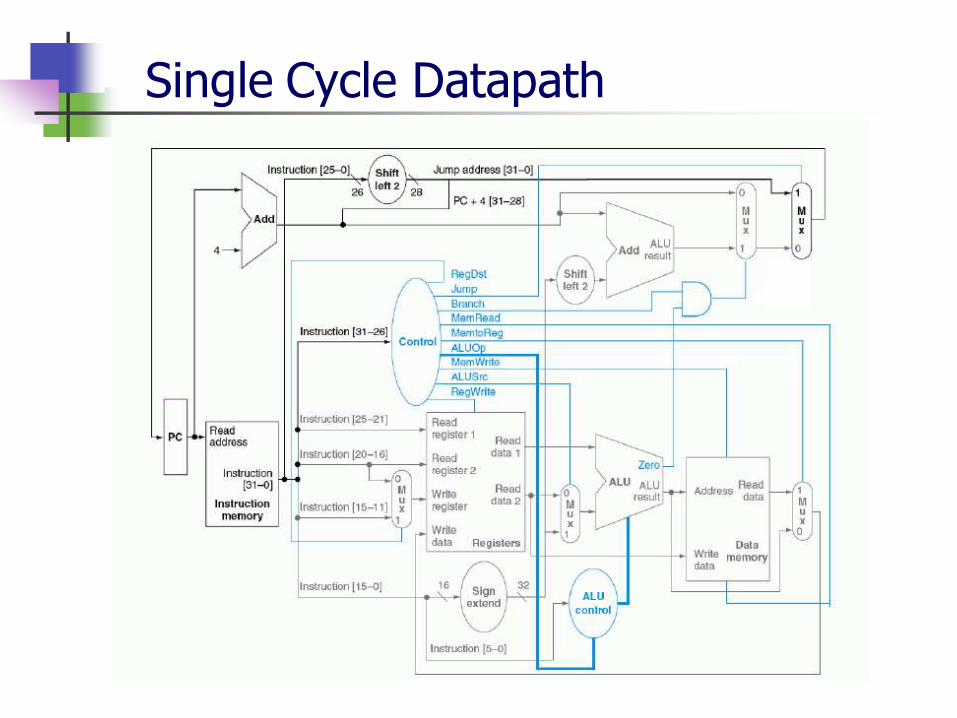
Single Cycle Datapath

Single cycle To . . . . . Next Design
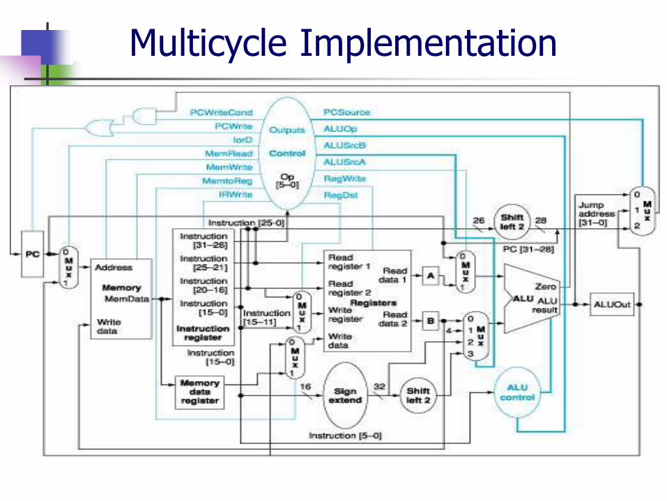
Multicycle Implementation
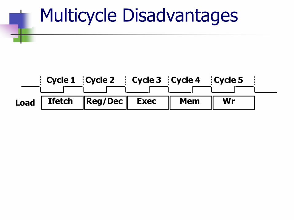
Cycle 1 Cycle 2 Cycle 3 Cycle 4 Cycle 5
Ifetch Reg/Dec Exec Mem Wr Load
Multicycle Disadvantages

Multicycle To . . . . . Next Design

7
CPU Pipelining
Can we pipeline instruction execution?
For the following instructions, which resources do you need for each of these steps? store/ load word
add/ subtract/ and/ or/ slt
branch if equal
8
CPU Pipelining
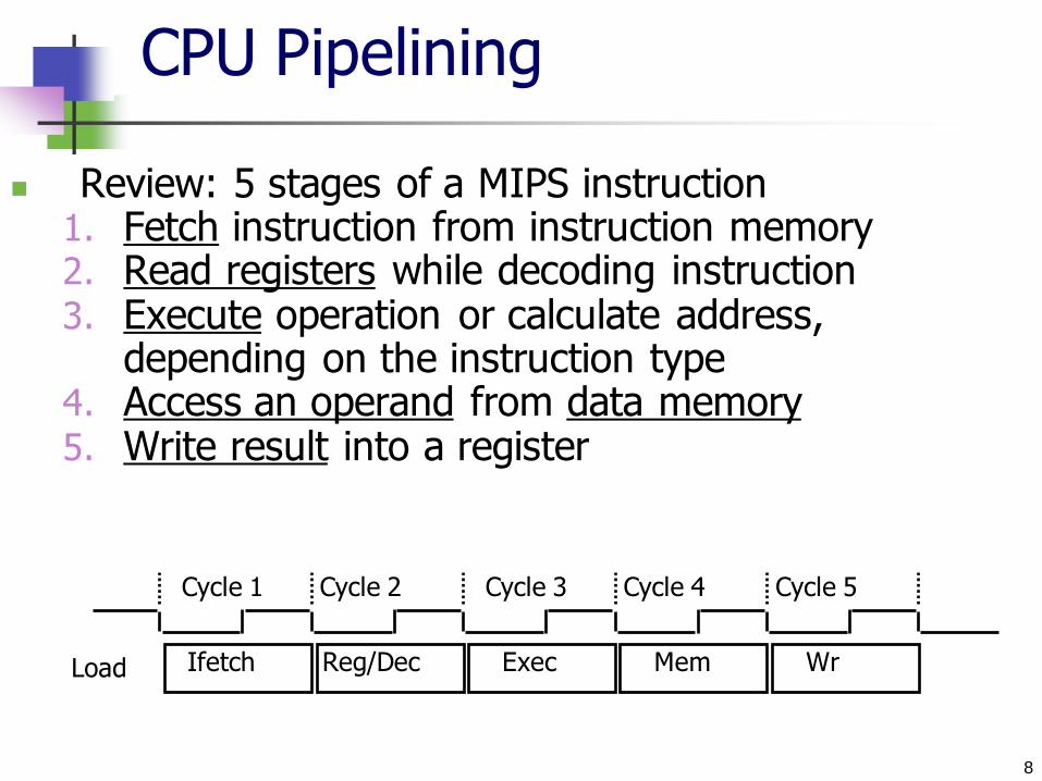
Review: 5 stages of a MIPS instruction 1. Fetch instruction from instruction memory 2. Read registers while decoding instruction 3. Execute operation or calculate address,
depending on the instruction type 4. Access an operand from data memory 5. Write result into a register
Cycle 1 Cycle 2 Cycle 3 Cycle 4 Cycle 5
Ifetch Reg/Dec Exec Mem Wr Load
9
CPU Pipelining
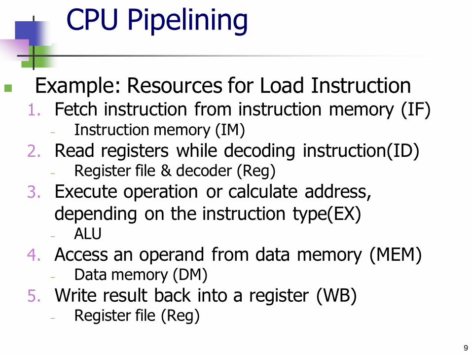
Example: Resources for Load Instruction 1. Fetch instruction from instruction memory (IF)
– Instruction memory (IM)
2. Read registers while decoding instruction(ID) – Register file & decoder (Reg)
3. Execute operation or calculate address,
depending on the instruction type(EX) – ALU
4. Access an operand from data memory (MEM) – Data memory (DM)
5. Write result back into a register (WB) – Register file (Reg)

10
CPU Pipelining: Example
Assumptions:
Only consider the following instructions:
lw, sw, add, sub, and, or, slt, beq
Operation times for instruction classes are:
Memory access 200 ps
ALU operation 200 ps
Register file read or write 100 ps
Use a single- cycle (not multi-cycle) model
Clock cycle must accommodate the slowest instruction
(200 ps)
Both pipelined & non-pipelined approaches use the same HW components
11
CPU Pipelining: Example
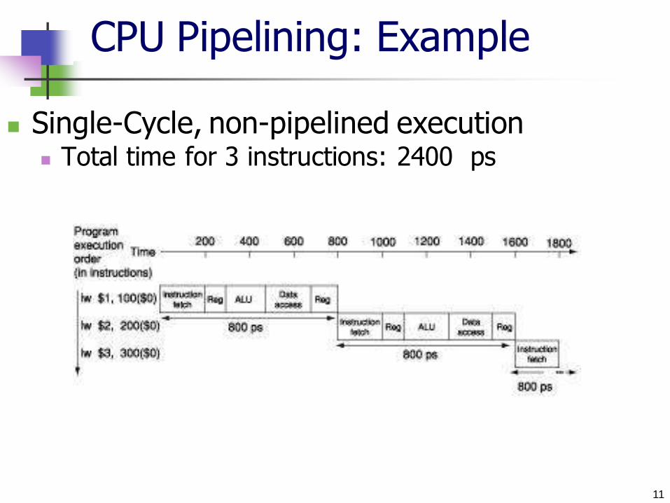
Single-Cycle, non-pipelined execution Total time for 3 instructions: 2400 ps

12
CPU Pipelining Example:
Instructions total times:
Assumption: For Single cycle instruction
Clock must be long enough to allow for the slowest instruction (800 ps)
Time between first and fourth instruction = 3 x 800 = 2400 ps
For Multi-cycle instruction
Each stage should accommodate the longest time for a stage (200 ps)
Instruction
Class
Instruction
Fetch
Register
Read
ALU
Operation
Data
Access
Register
Write
Total
Time
lw 200 ps 100 ps 200 ps 200 ps 100 ps 800 ps
sw 200 ps 100 ps 200 ps 200 ps 700 ps
add, sub, and, or, slt 200 ps 100 ps 200 ps 100 ps 600 ps
beq 200 ps 100 ps 200 ps 500 ps
13
CPU Pipelining Example:
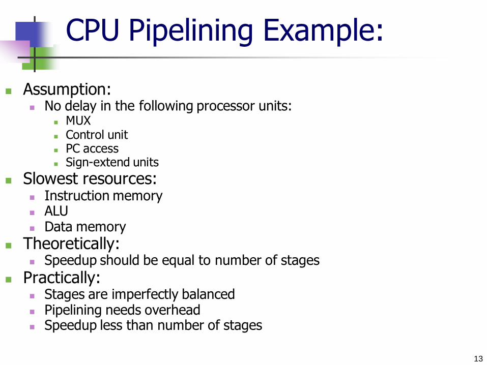
Assumption: No delay in the following processor units:
MUX Control unit PC access Sign-extend units
Slowest resources: Instruction memory ALU Data memory
Theoretically: Speedup should be equal to number of stages
Practically: Stages are imperfectly balanced Pipelining needs overhead Speedup less than number of stages
14
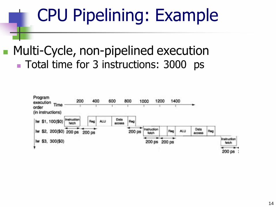
CPU Pipelining: Example
Multi-Cycle, non-pipelined execution Total time for 3 instructions: 3000 ps
15
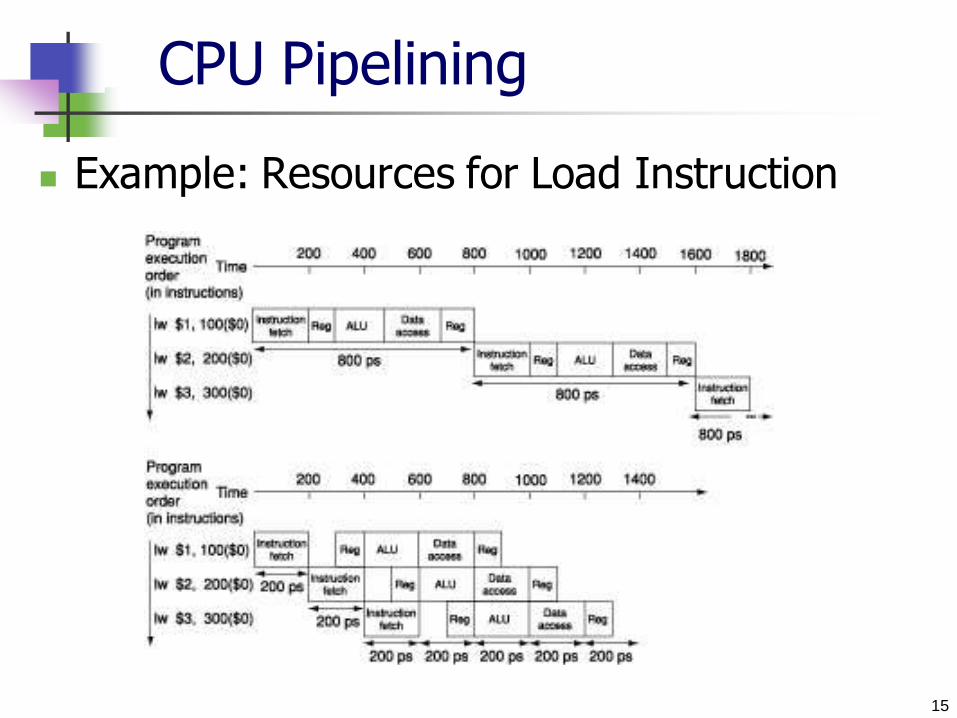
CPU Pipelining
Example: Resources for Load Instruction

16
CPU Pipelining
Note that accessing source & destination registers is
performed in two different parts of the cycle We need to decide upon which part of the cycle should
reading and writing to the register file take place.
Inst 0
Inst 1
Inst 2
Inst 4
Inst 3
I n s
t r. O r
d e r
Time (clock cycles)
ALU
Im Reg Dm Reg
ALU
Im Reg Dm Reg
ALU
Im Reg Dm Reg
ALU
Im Reg Dm Reg
ALU
Im Reg Dm Reg
Fill time Sink time
Reading Writing
17
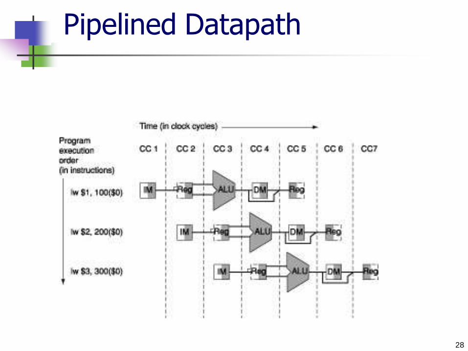
CPU Pipelining: Example
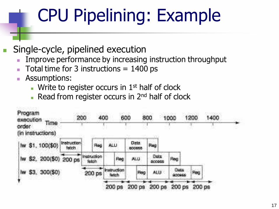
Single-cycle, pipelined execution Improve performance by increasing instruction throughput Total time for 3 instructions = 1400 ps Assumptions:
Write to register occurs in 1st half of clock Read from register occurs in 2nd half of clock

18
CPU Pipelining Example:
Instructions total times:
Assumption: Single cycle instruction
For non-pipelined Time between first and fourth instruction = 3 x 800 = 2400 ps
For pipelined Each stage should accommodate the longest time for a stage (200 ps)
Time between first and fourth instruction = 3 x 200 = 600 ps
Total time to execute the three instructions = ………..
Instruction
Class
Instruction
Fetch
Register
Read
ALU
Operation
Data
Access
Register
Write
Total
Time
lw 200 ps 100 ps 200 ps 200 ps 100 ps 800 ps
sw 200 ps 100 ps 200 ps 200 ps 700 ps
add, sub, and, or, slt 200 ps 100 ps 200 ps 100 ps 600 ps
beq 200 ps 100 ps 200 ps 500 ps

19
CPU Pipelining Example:
Assumption: No delay in the following processor units:
MUX Control unit PC access Sign-extend units
Slowest resources: Instruction memory ALU Data memory
Theoretically: Speedup should be equal to number of stages
Practically: Stages are imperfectly balanced Pipelining needs overhead Speedup less than number of stages

20
Pipelining MIPS Instruction Set
MIPS was designed with pipelining in mind
=> Pipelining is easy in MIPS:
1. All instruction are the same length
2. Limited instruction format
3. Memory operands appear only in lw & sw
instructions
4. Operands must be aligned in memory
21
Pipelining MIPS Instruction Set
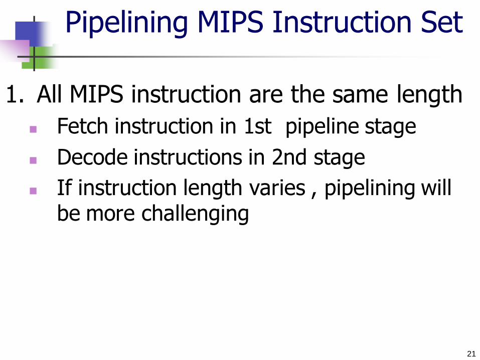
1. All MIPS instruction are the same length
Fetch instruction in 1st pipeline stage
Decode instructions in 2nd stage
If instruction length varies , pipelining will be more challenging
22
Pipelining MIPS Instruction Set
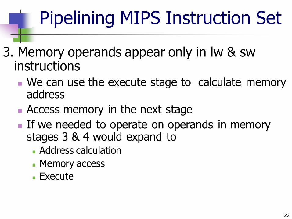
3. Memory operands appear only in lw & sw instructions We can use the execute stage to calculate memory
address
Access memory in the next stage
If we needed to operate on operands in memory stages 3 & 4 would expand to Address calculation
Memory access
Execute
23
Pipelining MIPS Instruction Set
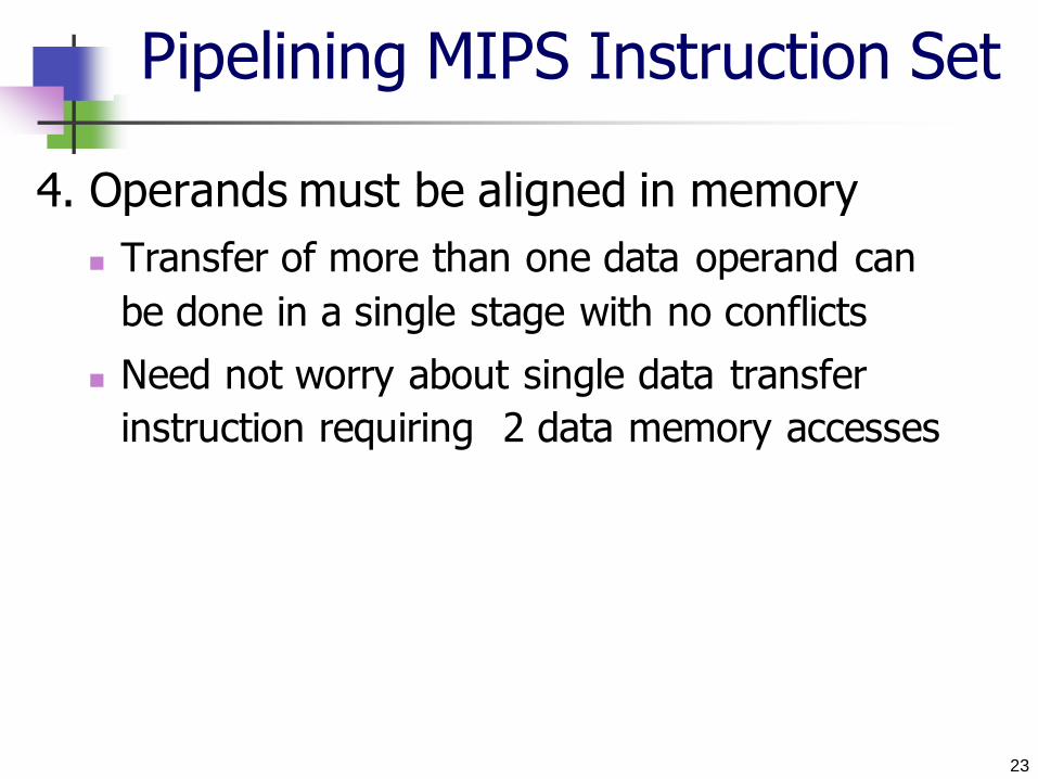
4. Operands must be aligned in memory
Transfer of more than one data operand can
be done in a single stage with no conflicts
Need not worry about single data transfer
instruction requiring 2 data memory accesses

24
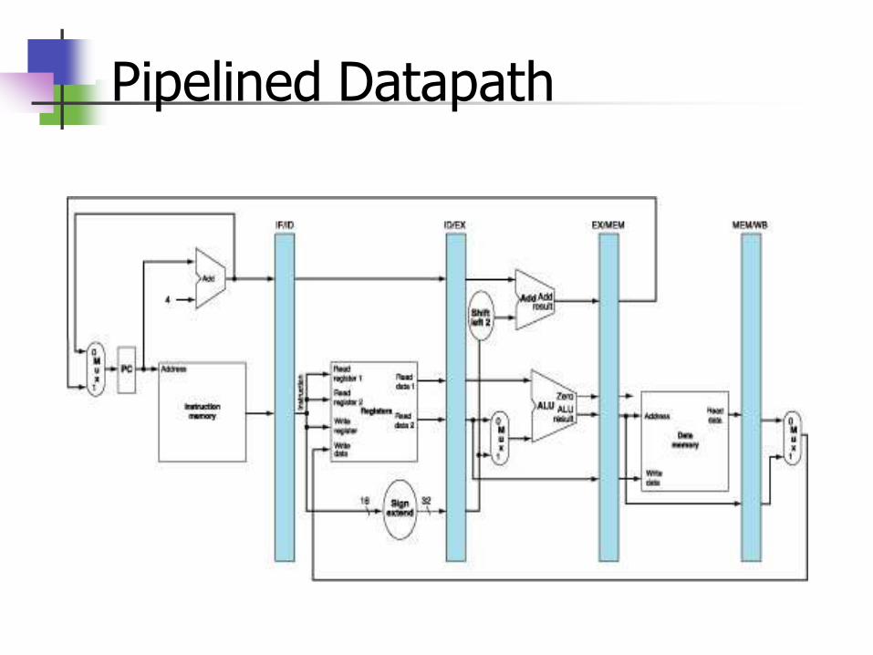
Pipelined Datapath
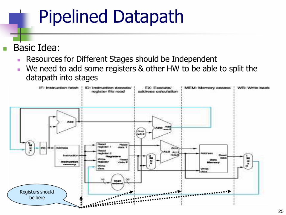
Basic Idea: Resources for Different Stages should be Independent We need to add some registers & other HW to be able to split the
datapath into stages
25
Pipelined Datapath
Basic Idea: Resources for Different Stages should be Independent We need to add some registers & other HW to be able to split the
datapath into stages
Registers should be here
Pipelined Datapath
27
Pipelined Datapath
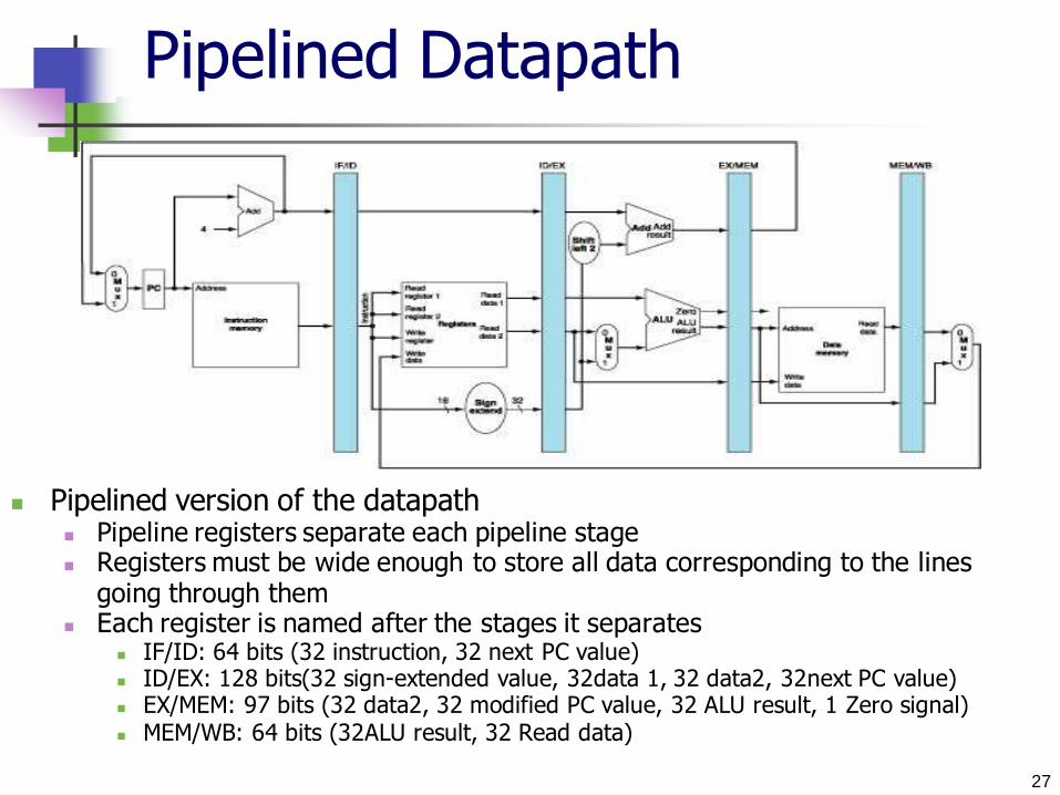
Pipelined version of the datapath Pipeline registers separate each pipeline stage Registers must be wide enough to store all data corresponding to the lines
going through them Each register is named after the stages it separates
IF/ID: 64 bits (32 instruction, 32 next PC value) ID/EX: 128 bits(32 sign-extended value, 32data 1, 32 data2, 32next PC value) EX/MEM: 97 bits (32 data2, 32 modified PC value, 32 ALU result, 1 Zero signal) MEM/WB: 64 bits (32ALU result, 32 Read data)
28
Pipelined Datapath

29
lw Instruction Execution
Step 1: Instruction fetch
30
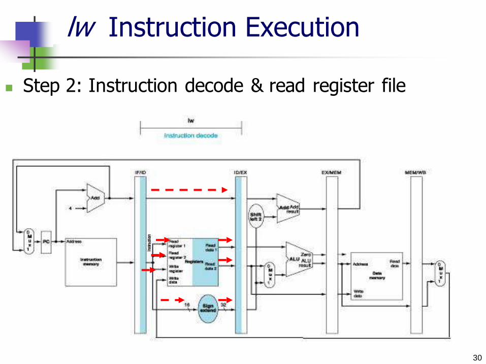
lw Instruction Execution
Step 2: Instruction decode & read register file
31
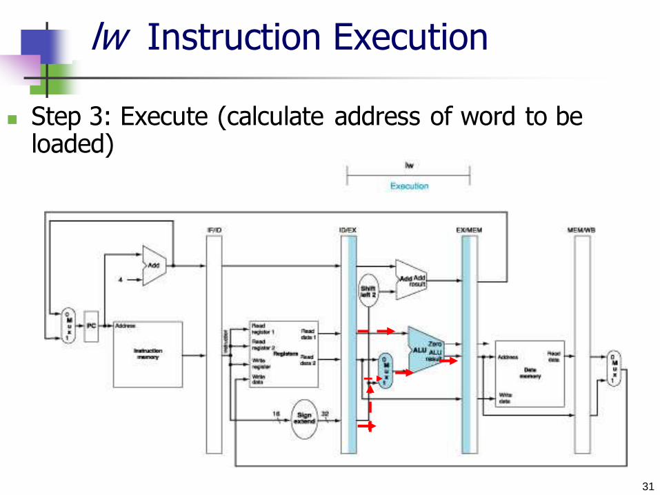
lw Instruction Execution
Step 3: Execute (calculate address of word to be loaded)
32
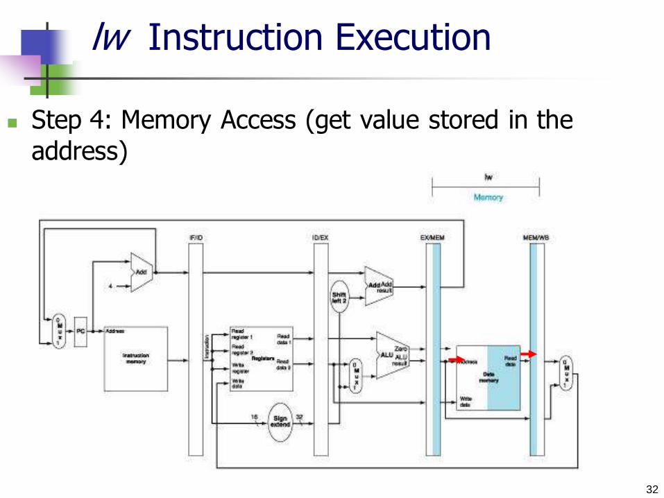
lw Instruction Execution
Step 4: Memory Access (get value stored in the
address)
33
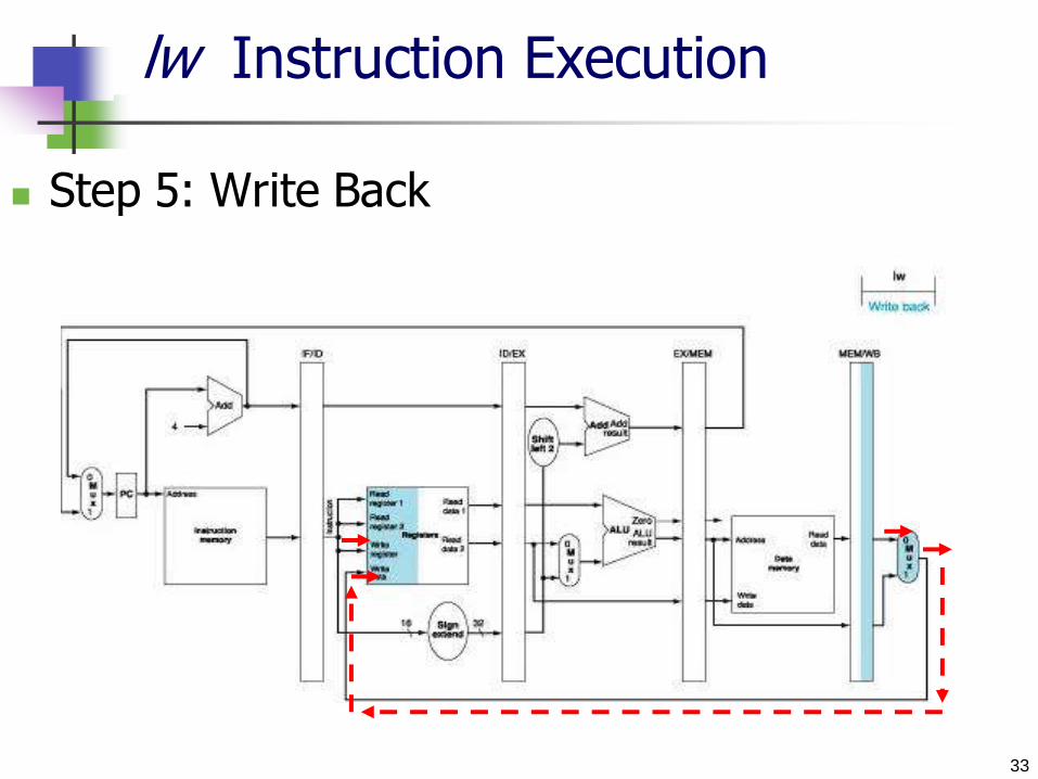
lw Instruction Execution
Step 5: Write Back
34
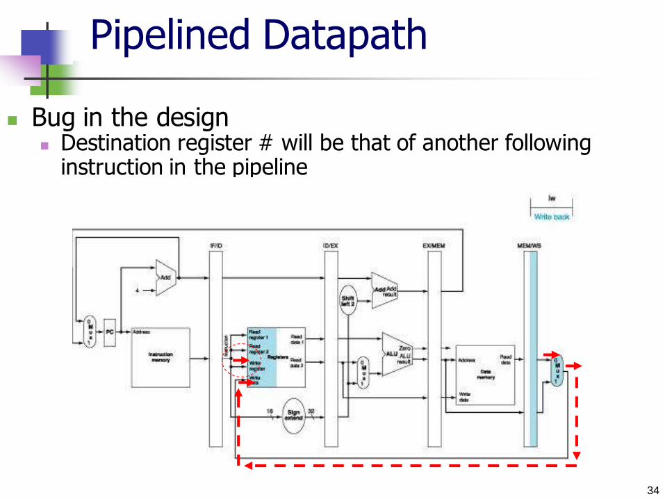
Pipelined Datapath
Bug in the design Destination register # will be that of another following
instruction in the pipeline

35
Pipelined Datapath
Correcting the design Bug Pass the register number from ID/EX, EX/MEM, MEM/WB to
be used in the WB stage

36
sw Instruction Execution
Step 1: Instruction fetch
37
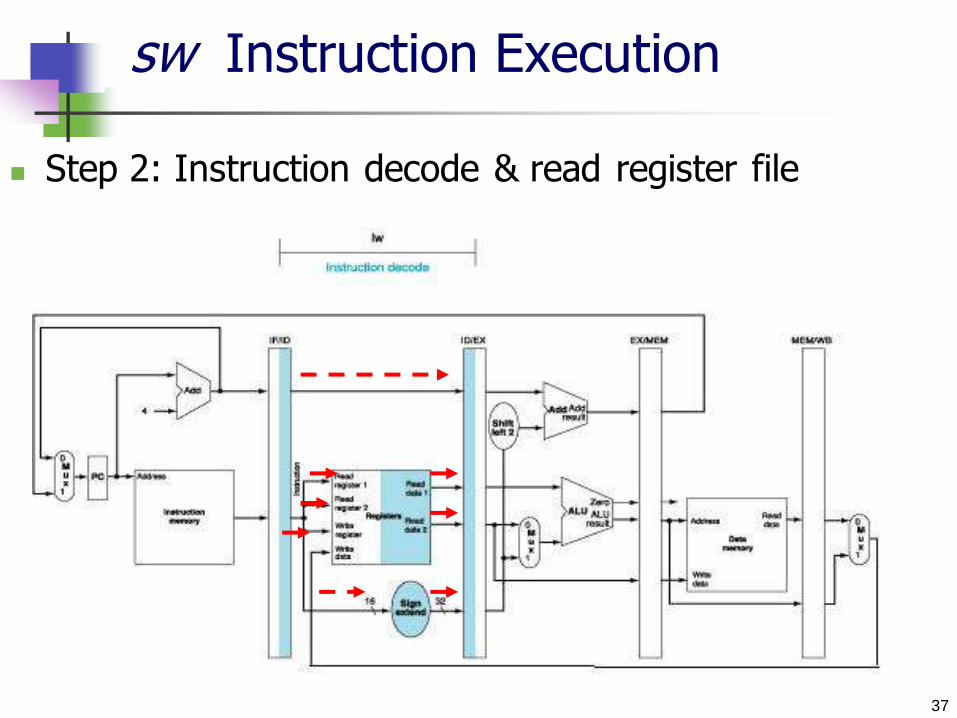
sw Instruction Execution
Step 2: Instruction decode & read register file

38
sw Instruction Execution
Step 3: Execute (calculate address of word to be stored)
39
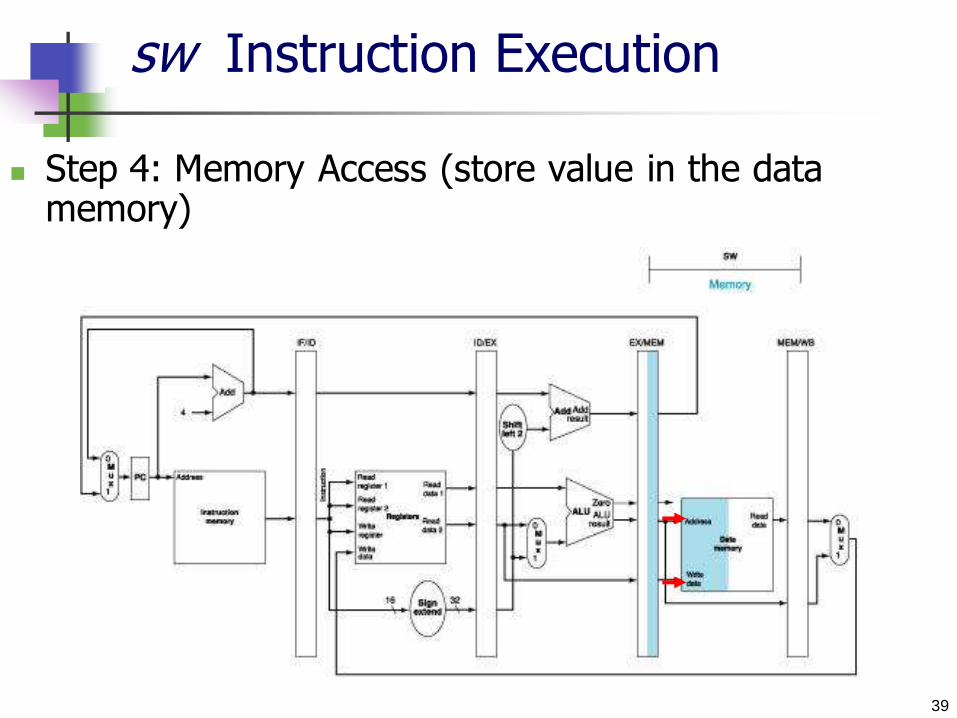
sw Instruction Execution
Step 4: Memory Access (store value in the data memory)
40
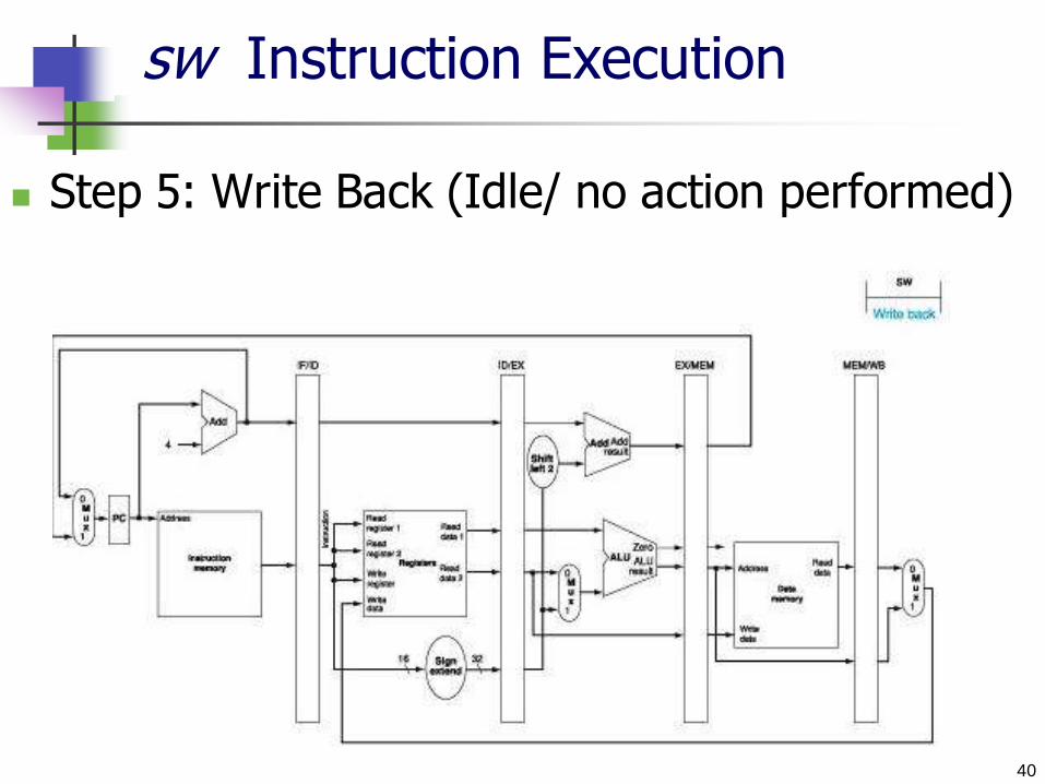
sw Instruction Execution
Step 5: Write Back (Idle/ no action performed)

41
Pipelined Datapath
Portion of datapath used by all 5 stages No conflict

42
Pipelined Datapath
Multiple-Cycle datapath
43
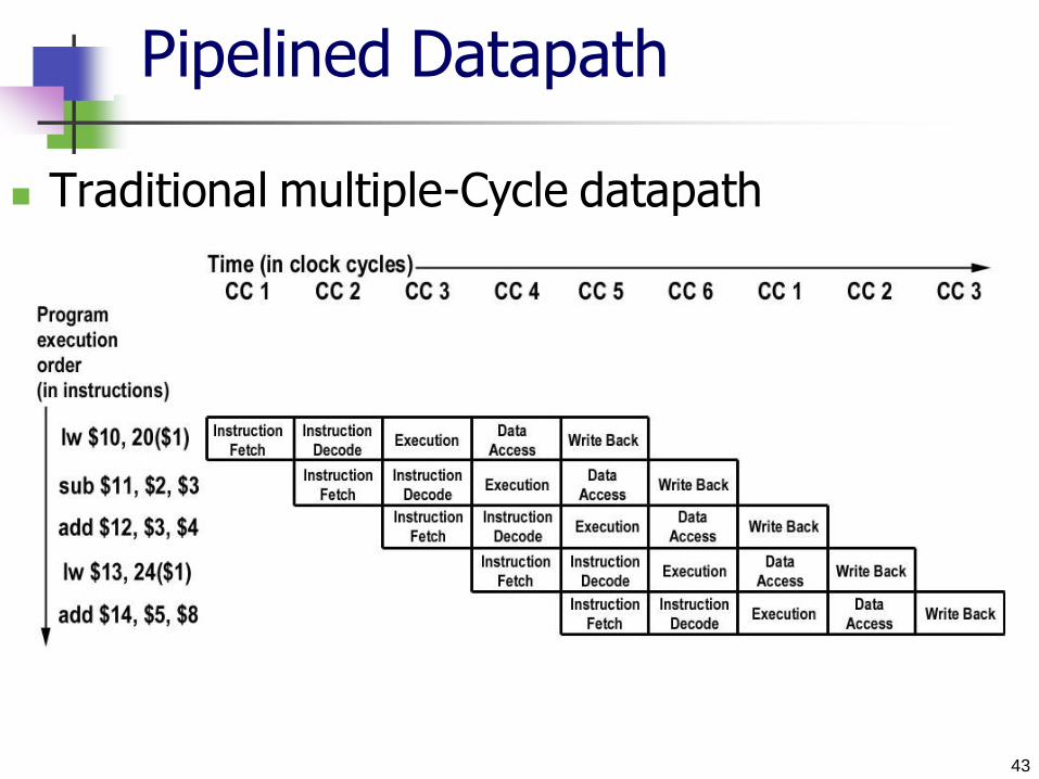
Pipelined Datapath
Traditional multiple-Cycle datapath
44
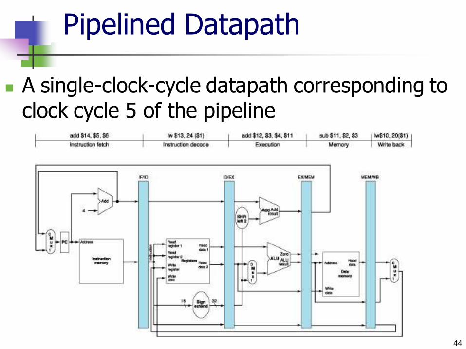
Pipelined Datapath
A single-clock-cycle datapath corresponding to clock cycle 5 of the pipeline
45
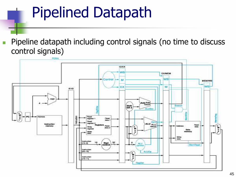
Pipelined Datapath
Pipeline datapath including control signals (no time to discuss control signals)

46
Pipeline Hazards
Hazard: Situation when next instruction cannot execute in
the following clock cycle
Types of Hazards
Structural hazards
Control hazards Data hazards
47
Structural Hazards
Attempt to use the same resource in two different
ways at the same time and the HW cannot support
the combination Example: If we use a single memory for both instruction &
data If we had more than 4 instructions,
1st instruction will be accessing data
4th instruction fetching the instruction
Both need to access the memory in the same clock cycle
Since MIPS was designed with two distinct memories, we
don’t encounter this problem
=> No hazards
48
Structural Hazards
Mem
I n s t r.
O r d e r
Time (clock cycles)
Load
Instr 1
Instr 2
Instr 3
Instr 4
ALU
Mem Reg Mem Reg
ALU
Mem Reg Mem Reg ALU
Mem Reg Mem Reg
ALU
Reg Mem Reg
ALU
Mem Reg Mem Reg
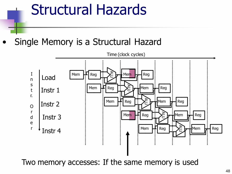
Two memory accesses: If the same memory is used
• Single Memory is a Structural Hazard
49
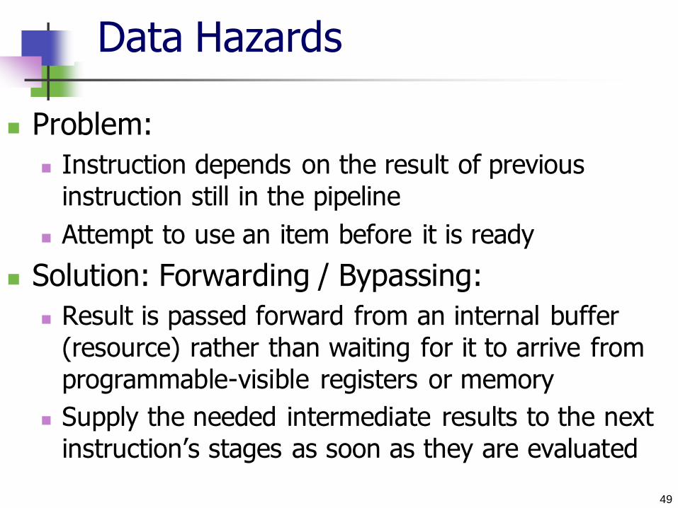
Data Hazards
Problem:
Instruction depends on the result of previous
instruction still in the pipeline
Attempt to use an item before it is ready
Solution: Forwarding / Bypassing:
Result is passed forward from an internal buffer
(resource) rather than waiting for it to arrive from
programmable-visible registers or memory
Supply the needed intermediate results to the next
instruction’s stages as soon as they are evaluated

50
Forwarding is valid if the destination stage is later in time than the source stage
Data Hazards
P r o g r a m e x e c u t i o n o r d e r ( i n i n s t r u c t i o n s )
I M R e g
I M R e g
s u b $ 2 , $ 1 , $ 3
a n d $ 1 2 , $ 2 , $ 5
o r $ 1 3 , $ 6 , $ 2
a d d $ 1 4 , $ 2 , $ 2
s w $ 1 5 , 1 0 0 ( $ 2 )
I M R e g D M R e g
I M D M R e g
I M D M R e g
C C 1 C C 2 C C 3 C C 4 C C 5 C C 6
T i m e ( i n c l o c k c y c l e s )
C C 7 C C 8 C C 9
1 0 1 0 1 0 1 0 1 0 / – 2 0 – 2 0 – 2 0 – 2 0 – 2 0 V a l u e o f r e g i s t e r $ 2 :
D M R e g
R e g
R e g
R e g
D M
Backward dependencies
are data hazards
Forward dependencies are
not hazards

51
Dependencies: Example:
Problem with starting next instruction before first is finished
sub instruction writes into $S2
All following instructions read $S2
Proper value is unavailable until the register is written (in cycle 5)
Dependencies that “go backward in time” are data hazards
Without intervention, a data hazard could severely stall the pipeline
Data Hazards
52
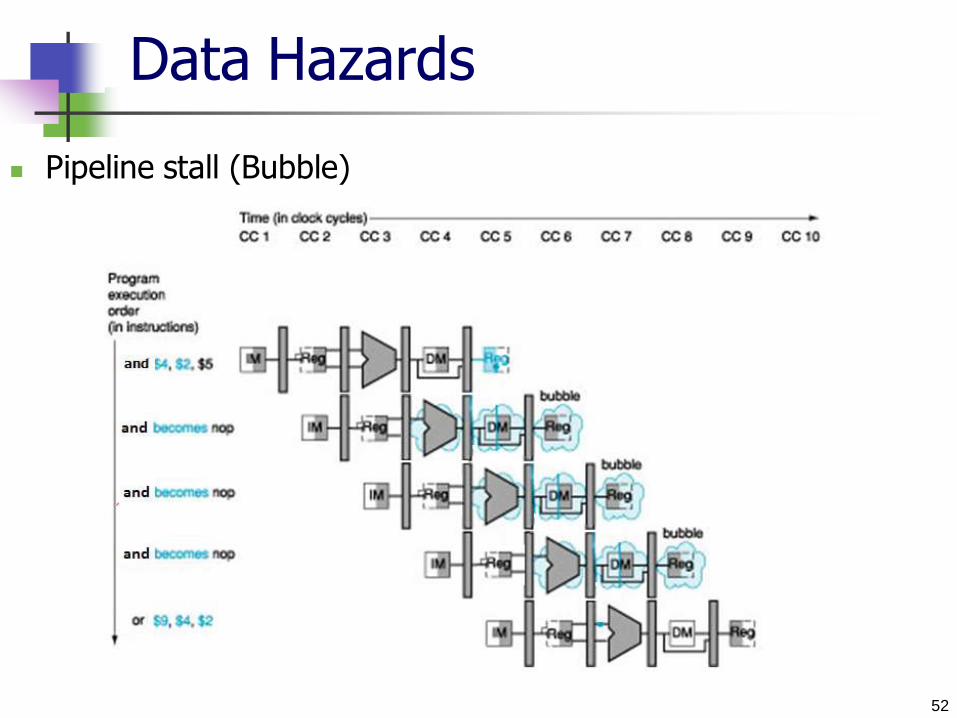
Data Hazards
Pipeline stall (Bubble)
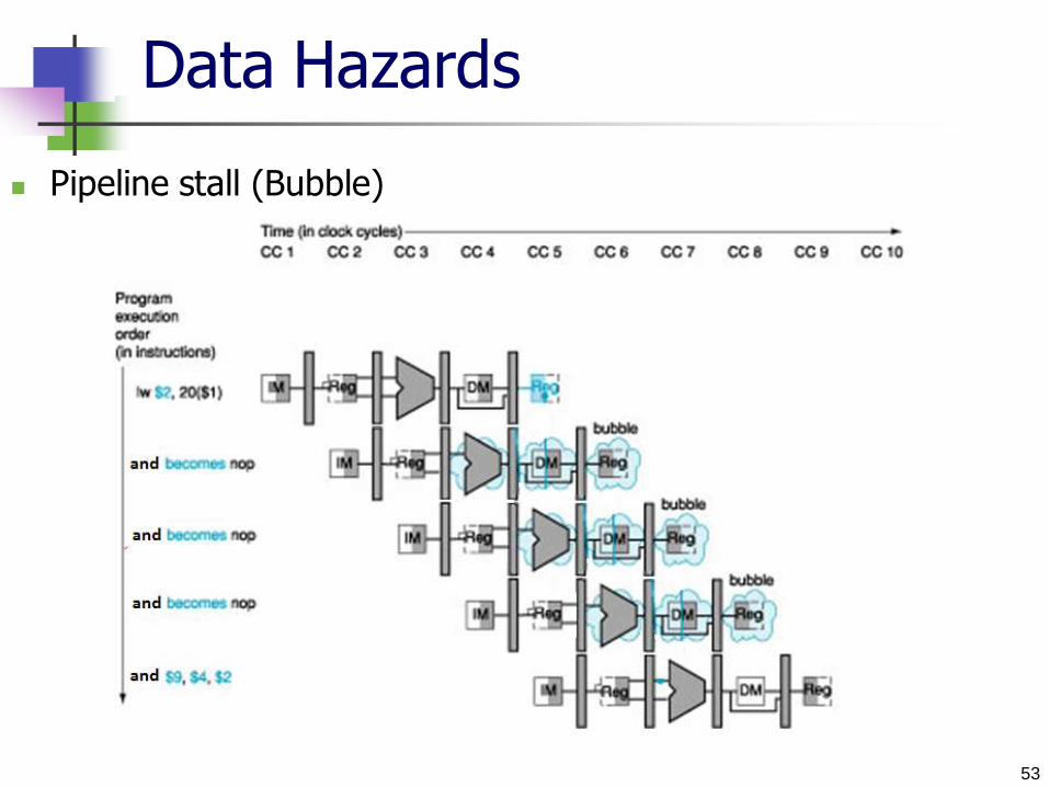
53
Data Hazards
Pipeline stall (Bubble)

54
Control (Branch) Hazards
Attempt to make a decision, which instruction to fetch, based on the result of another instruction
Occur less frequently than data hazards Can be solved by forwarding Major schemes:
Pipeline stall: Stall until the branch is complete Too slow
Prediction: Static branch prediction
Assume that the branch will not be taken and continue execution down the sequential instruction stream
Must retract if branch is taken; too costly if the pipeline is deep
Dynamic branch prediction Predict branch behavior during program execution
Delayed branch Execute statements that are not affected with the branch until the branch
result is clear
55
Control (Branch) Hazards
Pipeline stall (Bubble) on branch
Pause (wait) before continuing the pipeline, until
the decision is clear
Calculate the branch address, update PC during the
second stage
Disadvantage:
Too slow
Cost is too high for most computers

56
Control (Branch) Hazards
Pipeline when branch is not taken
If branch is not performed, no time is lost (no stall)
57
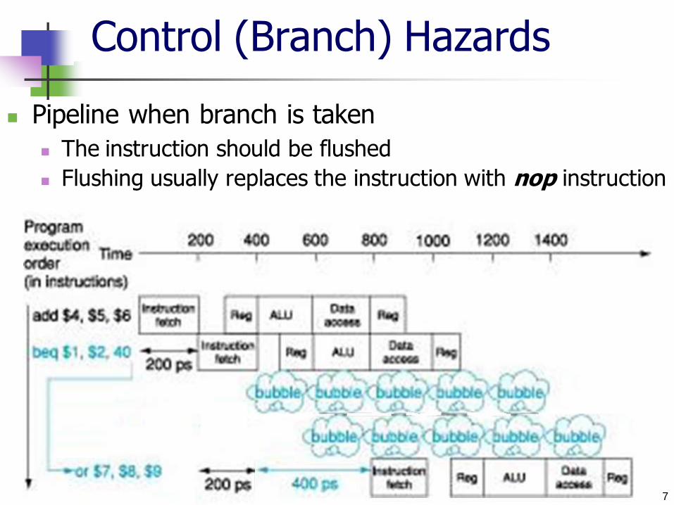
Control (Branch) Hazards
Pipeline when branch is taken
The instruction should be flushed Flushing usually replaces the instruction with nop instruction

58
Control (Branch) Hazards
Pipeline when branch is taken
The instruction should be flushed Flushing usually replaces the instruction with nop instruction
59
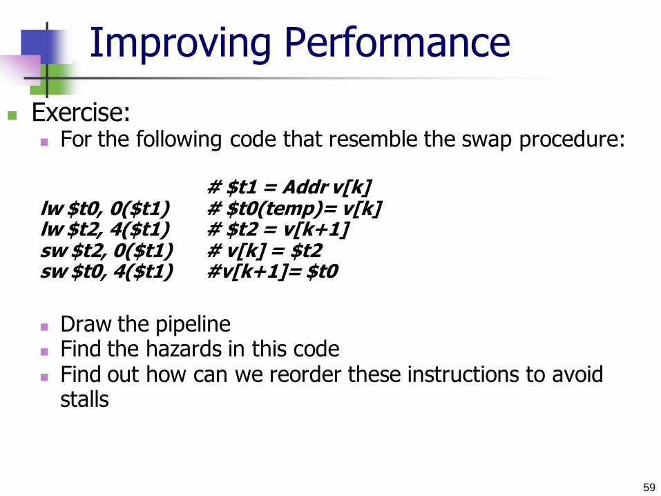
Improving Performance
Exercise: For the following code that resemble the swap procedure:
# $t1 = Addr v[k] lw $t0, 0($t1) # $t0(temp)= v[k] lw $t2, 4($t1) # $t2 = v[k+1] sw $t2, 0($t1) # v[k] = $t2 sw $t0, 4($t1) #v[k+1]= $t0
Draw the pipeline Find the hazards in this code Find out how can we reorder these instructions to avoid
stalls
60
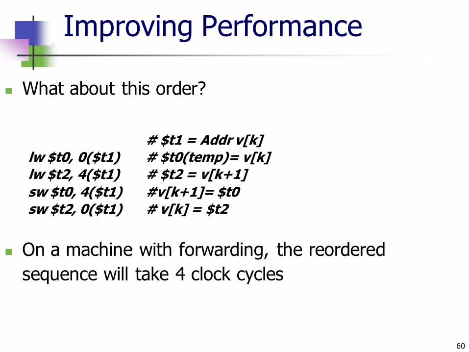
Improving Performance
What about this order?
# $t1 = Addr v[k]
lw $t0, 0($t1) # $t0(temp)= v[k]
lw $t2, 4($t1) # $t2 = v[k+1]
sw $t0, 4($t1) #v[k+1]= $t0
sw $t2, 0($t1) # v[k] = $t2
On a machine with forwarding, the reordered
sequence will take 4 clock cycles


![AASTMT | Homepage Lecturer: Prof. Ahmed Anas Elwogoud Course Coordinator: Dr Walid Maher Head of Department: Dr Mostafa Abdelgelil Page 1 of 2 Signature: [2 Marks] Date: 2 / 1 MPC](https://static.fdocuments.in/doc/165x107/5fa22d516a77036b3a3d7809/aastmt-lecturer-prof-ahmed-anas-elwogoud-course-coordinator-dr-walid-maher.jpg)

![Pipelining & Parallel Processing - ics.kaist.ac.krics.kaist.ac.kr/ee878_2018f/[EE878]3 Pipelining and Parallel Processing.pdf · Pipelining processing By using pipelining latches](https://static.fdocuments.in/doc/165x107/5d40e26d88c99391748d47fb/pipelining-parallel-processing-icskaistackricskaistackree8782018fee8783.jpg)