Energy Efficient Process Heating. Energy Balance on Furnace.

Wisconsin Weatherization Field Guide October 3, 2014 3-1
Chapter 3: Heating System Measures
3.1 Heating Systems
This chapter covers improvements to heating systems. The improvements include the
replacement or the modification and repair of the appliance. Complete combustion safety
testing for all systems and steady-state efficiency (SSE) testing on gas and oil heating
systems. All heating system work is completed by qualified professionals.
3.2 General Heating System Replacement
Observe the following standards for heating system replacement:
1. Install heating systems in accordance with manufacturer’s instructions and applicable
State and local codes.
2. Use existing distribution system and fuel supply line (when possible).
3. Properly remove and dispose of existing unit.
4. Provide an owner’s manual with heating system replacements.
5. New heating systems require a dedicated electrical circuit rated or fused to match the
amperage of the system’s requirements for overcurrent protection. Condensate pumps
are allowed to be on the same circuit.
6. Verify and make adjustments, if necessary, so that flue-gas oxygen, stack
temperature, and carbon-monoxide levels are within manufacturer's specifications. If
manufacturer’s specifications are not available, refer to Table 3-2 or Table 3-5.
7. Install a condensate pump where needed to reach an appropriate drain. See
Condensate Removal in Chapter 3 - Section 3.8.2 for more information about
condensate pumps.
8. Install condensate tubing or piping to reach an appropriate drain.
9. Seal openings in chimneys where natural-draft or fan assisted appliances are
eliminated. Indicate with a written notice on the chimney, where sealed, that the
chimney is no longer functional.
10. Provide in-home operation and maintenance instructions, as well as a review of safety
precautions to the customer.
11. Affix a tag, displayed prominently, that identifies who the customer should call for
service to the heating unit. The tag information shall contain the name, address, and
telephone number of the service organization.

Wisconsin Weatherization Field Guide October 3, 2014 3-2
3.3 Forced-Air Furnace Replacement
Observe the following standards specific to forced-air furnace installation:
1. Verify that the temperature rise is within manufacture’s limits as indicated on the
furnace label.
2. Set fan control for optimal efficiency without negatively impacting occupant comfort.
3. Perform all required tests and document results.
4. Seal holes through the jacket of the air handler with mastic or foil tape.
3.4 Forced-Air Furnace Air Distribution
Forced-air duct systems present opportunities for saving energy in homes. Ducts waste
energy through air leaks, lack of insulation, and airflow problems when they pass through
unconditioned spaces. This section addresses these forced-air distribution problems.
3.4.1 Duct System Modification
1. Add return or supply ductwork as part of furnace replacement to improve air
distribution to an acceptable level or to establish an acceptable value for temperature
rise (supply temperature minus return temperature). Add ductwork to address client
comfort or duct-induced pressure issues only with agency approval.
2. Do not add supply registers to the combustion-appliance zone (CAZ) unless it is an
intentionally heated part of the home. Consult with the customer about removing
existing grills in the CAZ. If grills are removed, document the customer consultation in
the file.
3. Mechanically fasten supply and return ductwork with screws. Seal the ductwork to the
furnace cabinet with mastic and fabric mesh tape, or other UL 181-approved material,
to form an essentially airtight connection on all sides of these important joints.
4. Do not install new ductwork in unconditioned spaces unless absolutely necessary. If
ducts are located in unconditioned spaces, seal the joints and insulate the ducts as
specified.
5. Connect new ducts to the existing distribution. Install a balancing damper in each new
branch supply duct. Install registers to terminate each new supply or return branch
duct.

Wisconsin Weatherization Field Guide October 3, 2014 3-3
3.4.2 Duct Leakage
Leaky ductwork poses two problems: it impacts the occupants’ health and safety, and it also
affects the home’s energy consumption.
Seal all ductwork that runs outside the dwelling’s heated envelope. These duct leaks waste
energy, and they also introduce health and safety hazards. For example, leaky supply ducts
can introduce excessive moisture into unheated spaces, and they also depressurize the
home. When return ducts leak in unheated spaces, they may serve to draw pollutants into
the distribution stream of air.
In the CAZ, return-ductwork leakage causes
depressurization and increases the likelihood that natural-
draft appliances will backdraft. Supply-side leaks in the
CAZ are less likely to cause backdrafts; rather, they may
aid the appliances’ natural draft by adding pressure to the
room.
Duct leakage that occurs inside the heated envelope is less
likely to contribute to increased energy consumption. The
leakage, however, may lead to an unintentional and
uneven distribution of heat throughout the home, with less
hot air distributing to the rooms where the occupants spend
much of their time.
Follow these instructions when sealing ductwork:
1. Seal all ducts that are located outside the thermal boundary.
2. Seal the connection between the furnace and the supply plenum, as well as the
connection between the furnace and the return drop.
3. Seal all gross holes in the supply and return ductwork.
4. Consider temporarily removing joist panning along the building’s exterior, to investigate
for air infiltration into the duct system. Replace joist panning when investigation is
complete.
5. After completing Steps 1-4, follow the diagnostic workbook to guide further sealing.
Materials for Duct Air-sealing
Duct mastic is the preferred duct-sealing material because of its superior durability and
adhesion. Apply mastic at least 1/16-inch thick and use reinforcing mesh or UL 181-
approved tape for all joints wider than 1/8-inch or joints that may experience some

Wisconsin Weatherization Field Guide October 3, 2014 3-4
movement. Silicone or siliconized acrylic-latex caulk is acceptable for sealing wood-to-wood
joints in panned joist spaces that function as return ducts.
Joints should rely on mechanical fasteners to prevent joint movement or separation. Tape
alone will not hold a joint together, and it will not resist the force of compacted insulation or
joint movement. Aluminum foil tape or cloth duct tape are not good materials for duct
sealing, because their adhesive often fails after a short time
3.4.3 Duct Insulation
Insulate forced-air ducts that run through unconditioned
areas with a minimum of R-10 foil-faced duct insulation.
Ducts may be insulated with two-part foam products that
meet the federal specification for duct insulation.
Do not apply duct insulation to ducts that will be
surrounded by R-10 or more of loose-fill insulation. Before
installing the loose-fill insulation, make sure to seal these
ducts.
Don’t insulate ducts that run through conditioned areas
unless they cause overheating in winter or condensation
in summer.
Follow these steps when installing duct insulation:
1. Perform necessary duct sealing before insulating
ducts.
2. Insulate all exposed forced-air ducts, without significant areas of bare duct left un-
insulated.
3. Fasten insulation mechanically, using stick pins, twine, plastic straps, or other
appropriate materials. Tape the joints in the insulation to prevent air convection, and
apply mastic over the tape to increase the tape’s longevity.
3.4.4 Measuring System Airflow
Low airflow is a common problem in forced-air duct systems. The air flow significantly
influences the temperature rise. Excessive air flow may cause customer-comfort issues.
Insufficient air flow may cause short-cycling or, in severe cases, a cracked heat exchanger.
The most common causes are too-small supply ducts, inadequate or restricted return ducts,
and dirty filters or coils. Table 3.1 shows recommended minimum air flow for various forced

Wisconsin Weatherization Field Guide October 3, 2014 3-5
air systems. When air flow measures lower than what is calculated with the multiplier, the
system is likely to have a temperature rise that is higher than that allowed by the
manufacturer.
Table 3-1: Recommended Minimum Air Flow (in CFM)
Furnace size Natural Fan-Assisted Sealed
in kBtu Draft Draft Combustion
40 400 520 600
50 500 650 750
60 600 780 900
75 750 975 1,125
100 1,000 1,300 1,500
Multiplier
kBtu x 10 13 15
To calculate the minimum air flow for a furnace, multiply the input kBtu's by the multiplier for the type of furnace. (i.e 55 x 15 = 825 CFM)
Preparing to Measure Airflow
Sophisticated test instruments are not necessary to discover that filters, air-conditioning coils
(A-coils), or blowers are packed with dirt or that the branch duct to the master bedroom is
disconnected. Diagnose these problems before measuring duct airflow. The following steps
precede airflow measurements:
1. Ask the customer about comfort problems and temperature differences in various parts
of the home.
2. Based on the customer’s comments, look for disconnected or restricted ducts.
3. Inspect the filter(s), blower fan, and A-Coil for dirt. Clean them if necessary. If the A-
coil isn’t easily visible, a dirty blower fan is a fair indicator that the A-coil may also be
dirty.
Flow-plate Method for Measuring System Airflow
The flow-plate meter is a plate with holes and sampling tubes that work in conjunction with a
digital manometer to measure the velocity and static pressures inside the ductwork. The
manometer then converts these values into an estimate of the distribution airflow.
The flow-plate meter will contain metering plates that can be configured to fit inside all
standard-size filter slots. Whenever possible, make sure that the plate is not bigger than the

Wisconsin Weatherization Field Guide October 3, 2014 3-6
return cutout in the furnace. See the instruction manual for the flow-plate meter for specific
directions on its use.
Measuring External Static Pressure
External static pressure (ESP) is the difference
between pressures in the supply and return
ductwork. ESP is the airflow resistance that is
caused by items external to the furnace cabinet.
The ESP test can be used to identify existing
ductwork issues such as insufficiently sized
ductwork or obstructed cold air returns. Testing
for ESP also allows for estimation of airflow if the
furnace manufacturer’s fan tables for static
pressure and airflow are available.
ESP equals the sum of the absolute values of the static pressures in the supply and return
sides. For example, a supply-side static pressure of +30 pascals and a return-side static
pressure of -80 pascals indicates an ESP of 110 pascals (80 + 30 = 110). The supply-side
static pressure will always be a positive number, and the return-side static pressure will
always be a negative number. The larger the ESP, the lower the airflow at a given fan
speed.
The ESP test requires a static-pressure probe, a
pressure hose, and a digital manometer. Follow these
steps to test the ESP of a forced-air heating system:
1. Install a clean furnace filter into the filter slot.
2. Drill one hole in the supply plenum, above the
furnace cabinet and below the A-coil drain pan
(if present). The hole must be large enough to
accommodate a static-pressure probe.
3. Drill a second hole on the return side, at a
location between the furnace filter and the air
handler. Depending on the location of the filter
slot, this hole may need to be drilled into the
furnace cabinet. (Use existing opening already
present in the furnace cabinet, rather than
drilling a new one.)

Wisconsin Weatherization Field Guide October 3, 2014 3-7
4. Set the digital manometer to “PR/PR” mode, and attach a pressure hose to the
Channel A Input tap.
5. Attach the static-pressure probe to the hose. Insert the probe into each of the holes,
and record the test result for each hole.
6. Add the absolute values of the two test results, treating each result as if it were a
positive number. This sum is the ESP for the heating system.
7. The higher the ESP measurement the
lower the airflow will be (assuming no
change in the air handler’s speed setting).
The manufacturers’ maximum
recommended ESP is usually 0.50 IWC for
standard air handlers. As ESP increases
above 0.50 IWC, the likelihood of
insufficient airflow increases. An exorbitant
ESP may indicate the presence of
constricted or insufficient ductwork, a
plugged A-coil or furnace filter, or other
distribution-system issues.
Use the ESP test as a guide, along with client conversations and the airflow and
temperature-rise tests, in determining whether the heating system has sufficient airflow.
3.4.5 Measuring Temperature Rise
Temperature rise is the temperature difference between
the supplied air and the return air. This test is critical in
determining if the furnace is set up and operating
properly. Perform the test after the furnace has reached
steady state and the duct work has heated up.
Measure the return temperature by inserting the
thermometer in the return drop prior to the filter. Measure
the supply temperature in a main duct as close to the
plenum as possible without being in the line of sight of
the heat exchanger. When there are multiple main ducts,
measure the temperature in each branch and use the
highest reading.

Wisconsin Weatherization Field Guide October 3, 2014 3-8
3.4.6 Filters
Observe the following standards related to furnace filter installation.
1. Supply the customer with furnace filters. Provide either:
a. Six 1” - 2” replaceable filters (one of these is installed); or
b. One washable filter (installed); or
c. One deep-pleated filter (installed).
2. Confirm that filters are held firmly in place and provide complete coverage of the
blower intake or the return register.
3. Ensure that filters are easy to replace.
4. Confirm that the heating system has a sealing filter cover, and install a new one if none
exists. Construct the new filter-slot cover so that it can be removed easily and safely.
Confirm that the filter is easy to access and replace. Magnetic filter covers are
allowable only if they provide an adequate seal to the ductwork to prevent air leakage.
3.5 Boiler Replacement
Complete all tests on the Hot Water Boiler Replacement
Check List and document results.
Follow these specifications when replacing boilers:
1. Flush the existing distribution system per
manufacturer’s instructions or until the water runs
clean and is free of sediment. With a zoned
system, flush each zone separately.
2. Locate stop valves at accessible points in the
supply and return pipe connections and as near to
the boiler as is convenient and practical to permit
draining the boiler without emptying the system.
3. Locate new zone valves near the boiler. Confirm that each zone has its own shut-off
valve.
4. Install a pressure-relief valve (PRV) per manufacturer’s instructions. Confirm that the
PRV is rated and sized correctly for the boiler BTU input and maximum operating
pressure.
5. Install an automatic fill valve, if none is present.
Cast-iron sectional boilers: The most
common boiler type for residential
application.

Wisconsin Weatherization Field Guide October 3, 2014 3-9
6. The feed-water (inlet) side of the pressure-reducing feed valve shall have a backflow
preventer, with a shut-off valve installed upstream from the backflow preventer; and
the boiler (outlet) side of the pressure-reducing feed valve also shall have a shut-off
valve, to allow for maintenance or replacement without draining the boiler system.
7. The backflow preventer shall have:
a. A drain facing the floor.
b. A pressure-reducing feed valve with either a purge valve or bypass piping with
a shut-off valve.
8. The system shall have an adequately sized expansion tank. Install an expansion tank,
or fill the existing expansion tank and the system to the correct level.
a. If the existing tank is a pre-pressurized diaphragm type and the tank is older
than 10 years, the expansion tank shall be replaced with a properly sized one.
9. Install the circulator pump near the downstream side of the expansion tank to prevent
the suction side of the pump from depressurizing the piping, which can pull air into the
piping.
10. Verify that return-water temperature is appropriate:
a. For oil boilers, verify that return-water temperature is above 150° F.
b. For non-condensing gas boilers, verify that return-water temperature is above
130° F, to prevent acidic condensation within the boiler.
11. Install piping bypasses, mixing valves, primary-secondary piping, or other strategies as
necessary to prevent condensation.
12. For condensing boilers, install condensation-resistant venting with condensation drains
designed into the venting system per the manufacturer’s specifications.
13. Insulate all pipes on the circulating loop between the boiler and an indirect domestic
water heater.
14. When installed on a floor below grade, a new boiler shall be installed above known
flood levels and as high as practical to avoid damage in case of flooding.
15. Inspect chimney for deterioration and correct sizing. Repair and reline the chimney as
necessary.
16. Install an electric vent damper where feasible for standard-efficiency boilers.

Wisconsin Weatherization Field Guide October 3, 2014 3-10
3.5.1 High-Efficiency (≥90%) Boilers
High-efficiency boilers often present significant energy-saving opportunities as compared
with standard-efficiency boilers. Similar to ≥90% efficient furnaces, high-efficiency boilers
cause water vapor in the exhaust gases to condense, which releases extra heat and raises
the efficiency potential above 90 percent. (High-efficiency systems are often referred to as
“condensing” systems.)
To size a replacement system accurately, consider the home’s design-temperature heat
loss, the room-by-room heat loss, and also the home’s existing radiation capacity. In
situations of insufficient radiation capacity, the home may need more heat emitters in order
to optimize the new system’s efficiency and to heat all rooms adequately.
With a high-efficiency boiler, the return water acts as coolant for the exhaust gases. The
lower the temperature of the return water, the more the exhaust gases cool — which in turn
increases the amount of water that condenses out of the exhaust, and thus increases the
boiler’s efficiency. For this reason, lower return-water temperatures correlate with increased
efficiencies.
Outside air temperature sensors are installed with a boiler to allow the boiler controls to
sense the actual outside temperature. Outdoor reset is a control function that allows the
boiler to adjust the supply-water temperature to the minimum needed to heat the building at
a given outside temperature. When the boiler limits its heat output to the dwelling’s actual
need, the lower supply-water temperature increases condensation and increases the boiler’s
efficiency.
High-efficiency boilers require regular maintenance. Some high-efficiency boilers are
especially vulnerable to problems with the distribution water — namely,
dirt/debris/sediment/rust in the water and also an improper pH level, both of which can lead
to plugged heat exchangers and other issues. Educate customers and make sure they
understand the maintenance requirements.
Follow these additional instructions when installing high-efficiency boilers:
1. Verify that flue-gas oxygen and CO (or CO2) are within the manufacturer’s ranges.
2. Equip the boiler with an outside air temperature sensor installed on a north-facing
exterior wall.
3. Program the boiler’s heating curve (outdoor reset) in line with the dwelling’s heat loss
and radiation capacity.
4. Setback thermostats are not recommended with boiler systems. This is because
following the setback period, the boiler may need a long time to reheat the dwelling.

Wisconsin Weatherization Field Guide October 3, 2014 3-11
5. Ensure that the distribution water’s pH level meets manufacturer’s specifications.
3.6 Hydronic Distribution Systems
Hydronic distribution systems consist of the supply and return piping, the circulator,
expansion tank, air separator, air vents, and heat emitters. A properly designed and installed
hydronic distribution system can operate for decades without service. Many systems,
however, have installation flaws or need service.
Boiler piping and controls present many options for zoning, boiler staging, and energy-
saving controls. Dividing homes into zones, with separate thermostats, can significantly
improve energy efficiency over operating a single zone. Modern hydronic controls can
provide different water temperatures to different zones with varying heating loads.
Follow these instructions for hydronic distribution systems:
1. Inspect radiators. Repair or replace as
necessary.
2. Bleed air from radiators and from the entire
system.
3. Confirm that the distribution system has no
leaks.
4. Modify the distribution system as
necessary to work properly with the
replacement boiler.
5. The system shall have automatic and manual air-bleed valves to eliminate air from all
high points in the distribution-piping system.
6. Extend new piping and radiators to conditioned areas, like
additions and finished basements that currently are heated
by space heaters.
7. Install thermostatically controlled radiator valves on the major
radiators; or zone controls; or outdoor reset and boiler
controls to adjust supply-water temperature according to
outdoor temperature, if feasible for the boiler system.
8. Insulate all supply piping outside conditioned spaces. For
hot-water systems, install 1½-inch fiberglass insulation on all
pipes less than or equal to 1½ inches in diameter, and 2-inch
fiberglass insulation on all pipes greater than 1½ inches in

Wisconsin Weatherization Field Guide October 3, 2014 3-12
diameter. For steam systems, install 1½-inch fiberglass insulation on all pipes less
than or equal to 1½ inches in diameter, and 3-inch fiberglass insulation on all pipes
greater than 1½-inch in diameter.
3.7 Boiler Efficiency and Maintenance
Boilers can maintain good performance and efficiency for many years if they are regularly
maintained and tuned-up. Boiler performance and efficiency improve after effective
maintenance and tune-up procedures.
Modern high-efficiency boilers require annual maintenance to achieve optimum performance
and life expectancy. The most significant energy wasters in hot-water systems are poor
steady-state efficiency, off-cycle flue losses robbing heat from stored water, and boilers
operating at too high a water temperature. For information about boiler installation, see
Boiler Replacement in Chapter 3 - Section 3.5.
Boiler performance and efficiency deteriorate in more ways than in forced-air furnaces.
Specifically these are:
1. Corrosion, scaling, and dirt on the water side of the heat exchanger.
2. Corrosion, dust, and dirt on the fire side of the heat exchanger.
3. Excess air during combustion from air leaks and
incorrect fuel-air mixture.
4. Off-cycle air circulation through the firebox and heat
exchanger, removing heat from stored water.
Consider the following maintenance and efficiency
improvements for both hot-water and steam boilers:
1. Check for leaks on the boiler, around its fittings, or
on any of the distribution piping connected to the
boiler.
2. Clean noticeable dirt from the fire side of the heat
exchanger.
3. Check doors and cleanout covers for air leakage. Replace gaskets, warped doors or
warped cleanout covers.
4. Drain water from the boiler drain until the water flows clean.

Wisconsin Weatherization Field Guide October 3, 2014 3-13
Safety Checks and Improvements
1. Confirm the existence of a 30-psi-rated pressure-relief valve. Replace a malfunctioning
valve or add one if none exists. Note signs of leakage or discharges, and find out why
the relief valve is discharging.
2. Make sure that the expansion tank isn’t waterlogged or sized too small for the system.
This could cause the pressure-relief valve to discharge. Test expansion tank for
acceptable air pressure — usually 12 to 22 psi.
Note: A hot-water boiler is recognized by its expansion tank, located somewhere
above the boiler. The expansion tank provides an air cushion to allow the system’s
water to expand and contract as it is heated and cooled without creating excessive
pressure in the boiler and piping and discharging through the pressure-relief valve.
3. If rust is observed in venting, verify that return water temperature is above 130° F for
gas and above 150° F for oil, to prevent acidic condensation.
4. Verify the system does not cycle on high limit.
5. Lubricate circulator pump(s) if necessary.
Efficiency Improvements
1. Repair water leaks in the system.
2. Remove corrosion, dust, and dirt on the fire side of the heat exchanger.
3. Check for excess air during combustion from air leaks and incorrect fuel-air mixture.
4. Confirm that the boiler does not have low-limit control for maintaining a minimum
boiler-water temperature, unless the boiler is heating domestic water in addition to
space heating.
5. Bleed air from radiators and piping through air vents on piping or radiators.
6. Consider installing outdoor reset controllers on non-high efficiency boilers to regulate
water temperature, depending on outdoor temperature.

Wisconsin Weatherization Field Guide October 3, 2014 3-14
7. After control improvements like two-stage thermostats or
reset controllers, verify that return-water temperature is
high enough to prevent condensation and corrosion in the
chimney as noted previously.
8. Consider installing a two-stage thermostat or timer control
to increase circulator on-time as compared with burner
on-time.
9. Vacuum and clean fins of fin-tube convectors if dust and
dirt is present.
10. Consider installing electric vent dampers on natural-draft gas- and oil-fired high-mass boilers.
3.8 Gas-Fired Heating Systems
3.8.1 Gas-Fired Heating-System Installation
The general procedures outlined in General Heating-System Replacement in Chapter 3 -
Section 3.2, should be followed. Complete all tests on the Replacement Gas Furnace Check
List and document results.
When replacing a gas-fired heating system:
1. Confirm that the clearances to nearby combustibles of the heating unit and its vent
connector conform with NFPA 54.
2. Clock the gas meter if necessary to troubleshoot oxygen, flue-gas temperature,
carbon-monoxide, or temperature-rise problems; and to verify that the actual gas input
matches with the nameplate input rating. Adjust gas input if necessary. See Measuring
BTU Input on Natural-Gas Appliances in Chapter 3 - Section 3.8.3.
3. Check the input gas pressure on the furnace when all gas-fired appliances are
operating in the house to ensure no drop-off in required gas pressure. If the input is
significantly different than the rating on the nameplate, all other variables above can be
affected.
4. Measure manifold gas pressure to ensure that it stays within the manufacturer’s
specified range. Adjust the fuel-air mixture for the lowest CO output and maximum
SSE.
5. Follow manufacturer’s venting instructions, along with the International Fuel Gas Code
(IFGC), to establish a proper venting system.

Wisconsin Weatherization Field Guide October 3, 2014 3-15
6. Follow manufacturer’s instructions for proper removal of condensate. See Condensate
Removal in Chapter 3 - Section 3.8.2.
7. Install a proper sediment trap on the gas line, if none exists.
8. When fuel-switching from oil to gas, place the old oil tank out of service in accordance
with Wisconsin Administrative Code SPS 310.315.
3.8.2 Condensate Removal
High-efficiency heating systems have a primary heat exchanger and a secondary heat
exchanger. Inside the secondary heat exchanger, water vapor in the furnace’s exhaust
condenses and thereby releases additional heat into the heating system. This release of
heat is what allows the furnace to achieve an Annual Fuel Utilization Efficiency (AFUE) of
90+ percent.
When the exhaust gas condenses, water forms inside the secondary heat exchanger. The
slightly acidic water, or condensate, must be piped away from the furnace and to an
appropriate drain.
Condensate is routed away from the furnace in one of two ways:
1) Running condensate tubing or piping directly from the furnace to an appropriate drain; or
2) Pumping the condensate from the furnace to an appropriate drain, using an electric
condensate pump.
Whenever feasible, pipe directly from the furnace to the floor drain, without installing a
condensate pump. Mechanically fasten the piping, either to the floor-drain strainer or to the
floor itself.
Ensure that the piping will not pose a tripping hazard to the occupants. Installing a “trip
strip”, with the customer’s approval, may be useful to prevent occupants from tripping over
the piping.
Sometimes, a direct-piping strategy will not be feasible. There may not be a drain near the
furnace, or perhaps the piping would pose a tripping hazard to the occupants. In these
situations, installing a condensate pump is likely a better option. See the next section for
information about condensate pumps.

Wisconsin Weatherization Field Guide October 3, 2014 3-16
Condensate Pumps
A condensate pump is installed when direct piping to an approved drain is not feasible.
Condensate pumps may be installed using existing receptacles, new ground-fault circuit
interrupter (GFCI) receptacles, or directly wired in accordance with pump manufacturer’s
requirements. Condensate is a slightly acidic byproduct of combustion. Building code
requires that it be drained to the sanitary sewer system, and not to the ground or to a sump
pump. The typical condensate receptors that code allows include a floor drain, a stand pipe,
or an indirect or local waste pipe served by a stand pipe or the laundry tray tail piece. An air
gap is required where the condensate line enters the
receptor. The condensate line cannot be tapped and
sealed directly into any drain pipe. See SPS 382.33
for Wisconsin code provisions regarding condensate
drains.
Floor Drain – The floor drain is the most common
method for discharging condensate. Condensate
lines that run to the drain must be secured to the floor
to keep them in place. This method works best when
the drain is not in a typical path of foot traffic.
Stand Pipe – The laundry stand pipe is often the best place to discharge condensate. If the
opening is not large enough for the washing machine hose and the condensate line, an
adapter can be added to enlarge the top of the pipe. A stand pipe cannot exceed 36 inches
in height above the centerline of the horizontal drain pipe. If an
existing stand pipe is not an option, a new standpipe, trapped
and vented, is acceptable. This option should be the last choice,
as the trap can dry out if the heating system does not discharge
condensate over an extended time
period. If a washing machine could
be discharged into the standpipe,
extend the standpipe at least 18
inches above the centerline of the
horizontal drain pipe.
Indirect or Local Waste Pipe – A vertical pipe that uses the trap
of a standpipe or laundry tailpiece is considered an indirect or
local waste pipe. It needs to be higher than the flood line of the
laundry tray or standpipe. This method can also be used if the
existing standpipe is full of other hoses.

Wisconsin Weatherization Field Guide October 3, 2014 3-17
3.8.3 Testing and Servicing Gas-Fired Systems
Gas burners should be cleaned and tuned every two to four years. Sometimes a
maintenance schedule will be posted on an existing heating system, allowing assessment of
the heating-system maintenance history (or lack thereof).
The goals of these service measures are to reduce carbon monoxide (CO), to optimize fuel-
air mixture, and to confirm the operation of safety controls. Complete all tests on the Heating
System Repair or Clean and Tune Check List and document results.
Perform the following inspection and maintenance procedures as necessary on gas-fired
furnaces, boilers, water heaters, and space heaters:
1. Inspect for soot, melted wire insulation, melted grommets, and rust in the burner and
manifold area outside the fire box. These all are indicators of flame rollout,
combustion-gas spillage, and CO production.

Wisconsin Weatherization Field Guide October 3, 2014 3-18
2. Inspect the burners for dust, debris, misalignment,
flame impingement, and other flame-interference
problems. Clean, vacuum, and adjust as needed.
3. Inspect the heat exchanger for leaks.
4. Verify that heating system wiring connections are
enclosed in covered electrical boxes.
5. Determine that the pilot is burning (if equipped) and
that main burner ignition is satisfactory.
6. Sample the undiluted combustion gases with a
calibrated flue-gas analyzer and record steady-state
efficiency, O2 percentage, CO ppm (as-measured),
and flue-gas temperature.
7. Clock the natural-gas meter, with all other gas
appliances off, to confirm that the input BTUs to
the furnace or boiler match with the nameplate
rating. Adjust gas pressure if necessary. See
Measuring BTU Input on Natural Gas
Appliances in Chapter 3 – Section 3.8.3 for
clocking the meter.
8. Clean the air handler (“squirrel cage”) and the
air-handler cabinet. Adjust the air handler’s
speed setting, if necessary, to ensure adequate
airflow and to ensure that temperature rise is
within the manufacturer’s specifications.
9. Test pilot-safety control for complete gas-valve
shutoff when pilot is extinguished.
10. When testing is complete, seal all test holes.
11. Verify that the thermostat’s heat-anticipator
setting matches the measured current in the 24-
volt control circuit.
12. Check venting system for proper size and pitch.
13. Check venting system for obstructions,
blockages, or leaks.
14. Measure chimney draft downstream of the draft diverter and check for spillage.
15. Measure gas input, and observe flame characteristics if soot, CO, or other combustion
problems are present.
Wisconsin Weatherization Field Guide October 3, 2014 3-19
16. Open a window while testing for CO to see if CO is reduced by increasing combustion
air.
A common furnace-efficiency problem is low fuel input and high O2 percentage, resulting in
poor heat transfer. This condition will be detected by combustion testing and clocking the
natural-gas meter. See the standards for O2 percentage and flue-gas temperature in Table
3-2.
Flue-gas temperature is another important indicator of furnace performance. A low flue-gas
temperature usually indicates efficient performance, since less of the heat is leaving the
building. If the flue-gas temperature is too low in older furnaces or 80+ furnaces, however,
acidic condensation will form in the vent. This acidic condensation can rust metal vents and
damage masonry chimneys.
Adjust gas pressure and airflow in order to optimize gas input, O2 percentage, flue-gas
temperature and SSE. These adjustments are best made while monitoring the exhaust gas
with the combustion analyzer.

Wisconsin Weatherization Field Guide October 3, 2014 3-20
Proceed with burner maintenance and adjustment when any of the following are present:
1. CO is greater than 100 ppm as measured or 200 ppm air-free;
2. Visual indicators of soot or flame roll-out exist;
3. Burners are visibly dirty;
4. Measured draft is inadequate;
Table 3-3: Combustion Problems and Possible Solutions
Problem Possible causes and solutions
Weak draft with CAZ depressurization
Return duct leaks, clothes dryer, exhaust fans, other chimneys. Seal return leaks. Provide make-up air.
Weak draft with no CAZ depressurization
Chimney blocked or leaky or else CAZ is too airtight.
Carbon monoxide Mixture too rich or too lean. Adjust gas pressure. Check chimney and combustion air for code compliance.
Stack temperature or heat rise too high or low
Adjust fan speed or gas pressure. Improve ducts to increase airflow.
Oxygen too high or low Adjust gas pressure, but don’t increase CO level.
Table 3-2: Typical Ranges for Gas Burning Appliances
Performance Indicator SSE 80+ SSE 90+
Carbon monoxide (CO) (ppm) ≤ 100 ≤ 100
Stack temperature (°F) 325° - 450° 90° - 120°
Temperature Heat rise (°F) 40° - 70° 30° - 70°
Oxygen (O2) 4-9% 4-9%
Gas pressure output at manifold - Inches of Water Column (IWC)
3.2 – 3.9 3.2 – 3.9
Propane pressure output at manifold (IWC)
10 – 11 10 – 11
Steady state efficiency (SSE) 82 – 86% 92 – 97%
Supply temperature (°F) 120° - 140° 95° - 140°

Wisconsin Weatherization Field Guide October 3, 2014 3-21
Gas-burner maintenance includes the following measures:
1. Remedy the causes of CO and soot. These causes may include over-firing, closed
primary air intake, flame impingement, and lack of combustion air.
2. Remove dirt, rust, and other debris that may be interfering with the burners. Clean the
heat exchanger, if necessary.
3. Take action to improve draft, if inadequate because of improper venting, obstructed
chimney, leaky chimney, or depressurization. See Improving Inadequate Draft in
Chapter 3 - Section 3.13.1.
4. Seal leaks in vent connectors and chimneys.
5. Adjust gas input if combustion testing or clocking the gas meter indicates over-firing or
under-firing.
Measuring BTU Input on Natural-Gas Appliances
1. Turn on the appliance to test, and then turn off all
other gas-combustion appliances (such as
heating systems, water heaters, dryers, cook
stoves, space heaters, etc.) that are connected to
the meter being timed.
2. Fire the appliance being tested, and watch the
dials of the gas meter.
3. Carefully count how long it takes for one
revolution of the 1/2-, 1-, or 2-cubic-foot dial. Find
that number of seconds in the columns marked “Seconds per Revolution” in Table 3-4.
Follow that row across to the right to the correct column for the 1/2-, 1-, or 2-cubic foot
dial. Multiply the number in the table by 1,000. Record the input in thousands of BTUs
per hour. For gauging a 1/4-cubic-foot dial, count how long it takes for 4 revolutions.
Then, use the 1-cubic-foot column to determine the input.
4. If the measured input is higher or lower than input on the nameplate by more than
10%, adjust gas pressure up or down, within the ranges in Table 3-3 on until the
approximately correct input is achieved.
5. For LP gas, determine the orifice size. From Table E.1.1 of the National Fuel Gas
Code, find the input BTU value that corresponds with the orifice size. Multiply the listed
BTU value by the number of orifices to get the input BTU for the heating system.
6. If the measured input is still out of range after adjusting gas pressure to these limits,
replace the existing orifices with larger or smaller orifices sized to give the correct
input. Any changes done to orifices must follow manufacturer’s instructions.

Wisconsin Weatherization Field Guide October 3, 2014 3-22
Table 3-4: Input in thousands of Btu/hr for 1000 Btu/cu. ft. gas
Seconds per
Revolution
Size of Meter Dial Seconds per
Revolution
Size of Meter Dial Seconds per
Revolution
Size of Meter Dial
½ cu. ft. 1 cu. ft. 2 cu. ft. ½ cu. ft. 1 cu. ft. 2 cu. ft. ½ cu. ft. 1 cu. ft. 2 cu. ft.
15 120 240 480 40 45 90 180 70 26 51 103
16 112 225 450 41 44 88 176 72 25 50 100
17 106 212 424 42 43 86 172 74 24 48 97
18 100 200 400 43 42 84 167 76 24 47 95
19 95 189 379 44 41 82 164 78 23 46 92
20 90 180 360 45 40 80 160 80 22 45 90
21 86 171 343 46 39 78 157 82 22 44 88
22 82 164 327 47 38 77 153 84 21 43 86
23 78 157 313 48 37 75 150 86 21 42 84
24 75 150 300 49 37 73 147 88 20 41 82
25 72 144 288 50 36 72 144 90 20 40 80
26 69 138 277 51 35 71 141 94 19 38 76
27 67 133 267 52 35 69 138 98 18 37 74
28 64 129 257 53 34 68 136 100 18 36 72
29 62 124 248 54 33 67 133 104 17 35 69
30 60 120 240 55 33 65 131 108 17 33 67
31 58 116 232 56 32 64 129 112 16 32 64
32 56 113 225 57 32 63 126 116 15 31 62
33 55 109 218 58 31 62 124 120 15 30 60
34 53 106 212 59 30 61 122 130 14 28 55
35 51 103 206 60 30 60 120 140 13 26 51
36 50 100 200 62 29 58 116 150 12 24 48
37 49 97 195 64 29 56 112 160 11 22 45
38 47 95 189 66 29 54 109 170 11 21 42
39 46 92 185 68 28 53 106 180 10 20 40

Wisconsin Weatherization Field Guide October 3, 2014 3-23
3.8.4 Leak-Testing Gas Piping
For information on leak-testing gas piping, see Leak-Testing Gas Piping in Chapter 5 –
Section 5.3.5.
3.9 Oil-Fired Heating Systems
3.9.1 Oil-Fired Heating-System Installation
The general
procedures outlined in
General Heating
System Replacement
in Chapter 3 - Section
3.2 should be followed
when replacing an oil
heating system.
Complete all tests on
the Oil Replacement
Furnace Check List
and document results.
When replacing an oil furnace:
1. Properly size the nozzle based on the post-weatherization conditions, using
REScheck®, Manual J, or an equivalent industry-accepted sizing formula. Document
the nozzle size on the inside of the furnace cabinet, next to the furnace nameplate.
2. Examine the existing chimney and vent connector for suitability as venting for the new
appliance. The vent connector may need to be resized, and the chimney may need to
be relined.
3. Confirm that the clearances to nearby combustibles of the heating unit and its vent
connector conform with NFPA 31.
4. Test oil pressure, and verify that it complies with manufacturer’s specifications.
5. Test control circuit amperage, and adjust the thermostat’s heat anticipator to match.
6. Test smoke number to confirm that it meets manufacturer’s specifications. See Table
3-5.

Wisconsin Weatherization Field Guide October 3, 2014 3-24
7. Install a new fuel filter, and purge the fuel lines.
8. Verify that the chimney operates safely and in accordance with NFPA 211.
9. Confirm that the tank and oil lines comply with NFPA 31.
3.9.2 Testing and Servicing Oil-Fired Systems
Oil burners require annual
maintenance to retain their
operational safety and
combustion efficiency. Testing for
steady-state efficiency, draft,
carbon monoxide, and smoke
should be used to guide and
evaluate maintenance. These
clean-and-tune procedures
pertain to oil-fired furnaces,
boilers, and water heaters.
Oil-Burner Inspection and Testing
Evaluate oil-burner operation by visually inspecting and combustion-testing the system. An
oil burner passing visual inspection and giving good test results may need minimal
maintenance. If the test results are fair, adjustments may be necessary. Unsatisfactory test
results may indicate the need to replace the burner or the entire heating unit.
Follow these steps to improve oil-burner safety and efficiency:
1. Inspect burner and appliance for signs of soot, overheating, fire hazards, corrosion, or
wiring problems.
2. Equip all oil-fired heating systems with a barometric draft control, unless the system
has high-static burners.
3. Confirm that the oil heating system has a dedicated electrical circuit.
4. Enclose all 120-volt wiring connections in covered electrical boxes.
5. Inspect fuel lines and storage tanks for leaks.
6. Inspect heat exchanger and combustion chamber for cracks, corrosion, or soot
buildup.
7. Check to see if flame ignition is instantaneous or delayed. Flame ignition should be
instantaneous, except for pre-purge units where the blower runs for a while before
ignition.

Wisconsin Weatherization Field Guide October 3, 2014 3-25
8. Sample undiluted flue gases with a smoke tester, following the smoke-tester
instructions. Compare the smoke smudge left by the gases on the filter paper with the
manufacturer’s smoke-spot scale to determine smoke number. With a smoke number
of Two or higher, do not use the electronic combustion analyzer.
9. Analyze the flue gas for O2 percentage, temperature, CO ppm, and steady-state
efficiency (SSE). Sample
undiluted flue gases
between the barometric
draft control and the
appliance. Adjust fuel-air
mixture and airflow to
conform to standards in
Table 3-5.
10. Measure flue draft between
the appliance and
barometric draft control and
over-fire draft over the fire
inside the firebox.
11. Measure high-limit shut-off
temperature, and adjust or
replace the high-limit control
if the shut-off temperature is more than 250°F for furnaces or 180°F for hot-water
boilers.
12. Measure oil-pump pressure, and adjust to manufacturer’s specifications if necessary.
13. Measure transformer voltage, and replace transformer if not within the allowable range.
14. Ensure that barometric draft controls are mounted plumb and level, and that the
damper swings freely.
15. Time the cad cell control or stack control to verify that the burner will shut off, within
the time frame per manufacturer’s specifications, when the cad cell is blocked from
seeing the flame.
Oil-Burner Maintenance and Adjustment
After evaluating the oil burner’s initial operation, perform the following maintenance tasks as
needed to optimize safety and efficiency:
1. Verify correct flame-sensor operation.
2. Replace burner nozzle after matching the new nozzle’s size to the home’s post-
weatherization heat-load requirements.
Table 3-5: Typical Ranges for Oil Burning Appliances
Performance Indicator Non-Flame Retention
Flame Retention
Carbon monoxide (CO) (ppm) ≤ 100 ≤ 100
Stack temperature (°F) 325° - 550° 300° - 450°
Oxygen (O2) 6-9% 5-9%
Smoke number (1-9) ≤ 2 ≤ 1
Excess air (%) ≥ 80% ≥ 35%
Oil pressure pounds per square inch (psi)
≥ 100 100 -150
Over-fire draft (Inches of Water Column - IWC negative)
.02 IWC or 5 Pa
.02 IWC or 5 Pa
Flue draft (IWC negative) .04 -.01 IWC or 10-15 Pa.
04 -.01 IWC or 10-15 Pa.
Steady state efficiency (SSE) ≥ 75% ≥ 80%

Wisconsin Weatherization Field Guide October 3, 2014 3-26
3. Clean the burner’s blower wheel.
4. Replace oil filter(s).
5. Clean or replace air filter. See “Filters” in Section 3.4.6 for guidance on providing
furnace filters.
6. Remove soot and sludge from combustion chamber.
7. Remove soot from heat-exchange surfaces.
8. Clean dust, dirt, and grease from the burner assembly.
9. Ensure that the oil pump is set to the correct pressure.
10. Adjust air shutter to achieve O2 and smoke values, specified in Table 3-5.
11. Adjust barometric damper for a negative flue draft of 10–15 pascals or 0.04-to-0.06
IWC (before barometric damper).
12. Adjust gap between electrodes and their position in burner tube, per manufacturer’s
specifications.
13. Repair the ceramic combustion chamber, or replace it if necessary.
14. Inspect and clean end of the burner-tube assembly. Replace flame-retention head if
damaged.
Wisconsin Weatherization Field Guide October 3, 2014 3-27
15. Inspect and clean transformer contacts to remove any corrosion.
After these maintenance procedures, perform the diagnostic tests described previously to
evaluate improvement made by the maintenance procedures and to determine if fine-tuning
is required.
3.10 Electric Furnaces and Electric Baseboard Heat
In Wisconsin, electric baseboard heat is much more common than electric furnaces. Due to
the high cost of electricity, these systems may be good candidates for fuel-switching.
Caution: Disconnect power from electric furnaces before performing any maintenance.
1. Check or clean and lubricate the following components: thermostat, blower, housing
around electric element, baseboard fins.
2. Clean or replace all filters.
3. Take extra care in duct sealing and in duct-airflow improvements for electric furnaces
because of the high cost of electricity.
4. Verify that safety limits and temperature rise conform to manufacturer’s specifications.
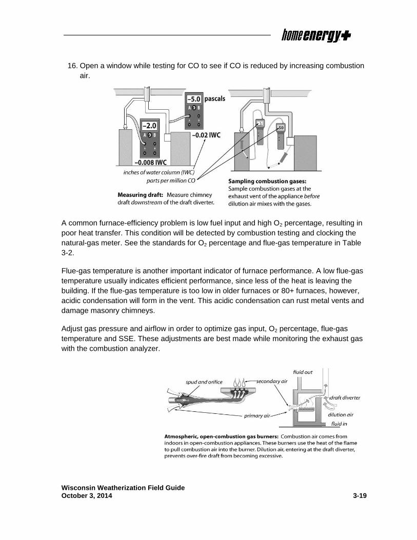
3.11 Replacing Space Heaters
When replacing a space heater:
1. Follow manufacturer’s venting instructions
carefully. Don’t vent sealed-combustion,
induced-draft space heaters into naturally
drafting chimneys.
2. If the space heater will sit on a carpeted floor,
provide a fire-rated floor protector, sized to
the width and length of the space heater, as a
base.
3. Locate space heater away from traffic,
draperies, and furniture.
4. Space heaters require a properly grounded
duplex receptacle for electrical service.

Wisconsin Weatherization Field Guide October 3, 2014 3-28
Inform the client of the following operating instructions:
1. Don’t store any objects near the space heater that would
restrict airflow around it.
2. Don’t use the space heater to dry clothes or for any purpose
other than heating the home.
3. Don’t allow anyone to lean or sit on the space heater.
4. Don’t spray aerosols near the space heater. Many aerosols
are flammable or can cause corrosion to the space heater’s
heat exchanger.
3.12 Replacing Wood Stoves
Wood stoves that have a crack or hole in the fire box should be replaced. Units that do not
meet clearances and cannot be corrected should be considered for replacement. All
replacement wood stoves must meet applicable local codes and EPA requirements.
Installations must conform to the NFPA 211.
When replacing a wood stove:
1. Install the stove to meet manufacturer’s specifications.
2. Verify that the replacement stove is certified to meet EPA emission standards or local
standards, whichever are stricter.
3. Confirm that the installed unit is certified and labeled by:
a. National Fire Protection Association under 211-1996; or
b. International Conference of Building Officials; or
c. Other equivalent listing organization.
4. Visually inspect the chimney for safe operation by referring to NFPA 211.
5. Provide all clients with in-home operation instructions, to include proper wood-burning
practices; safety information; and education about proper maintenance, such as stack
thermometers and the need for fire extinguishers.
6. Educate the customers about the potential impact of exhaust ventilation and/or forced-
air distribution on the wood heater’s operation.
7. Install make-up air if the building is tightened below the Depressurization Limit CFM50.

Wisconsin Weatherization Field Guide October 3, 2014 3-29
3.13 Venting Combustion Gases
Proper venting is essential to the operation, efficiency, safety and durability of combustion
heaters. The National Fire Protection Association (NFPA) and the International Code
Council (ICC) are the authorities on material-choice, sizing, and clearances for chimneys
and vent connectors, as well as for combustion air. The information in this venting section is
based on the following NFPA and ICC documents:
The International Fuel Gas Code (IFGC) (ICC)
NFPA 31: Standard for the Installation of Oil-Burning Equipment
NFPA 211: Standard for Chimneys, Fireplaces, Vents, and Solid-Fuel- Burning
Appliances
Table 3-6: Guide to Venting Standards
Topic Code Reference
Venting Sizing IFGC, Section 504
Clearances
IFGC, Section 308 and Tables 308.2l NFPA 31, Section 4-4.1.1 and Tables 4-4.1.1 and 4-4.1.2 NFPA 211, Sections 6.5, 4.3, 5
Combustion Air IFGC, Section 304 NFPA 31, Section 1-9; NFPA 211, Section 8.5 and 9.3
3.13.1 Improving Inadequate Draft
If measured draft is below the minimum worst-case requirement, investigate the reason for
the weak draft. Open a nearby window, exterior door, or interior door to observe whether the
addition of make-up air will improve draft. If the added air strengthens draft, then the
problem usually is depressurization. If opening a window has no effect, inspect the chimney.
The chimney could be blocked or excessively leaky.
Chimney Improvements to Solve Draft Problems
Consider the following chimney improvements when attempting to improve worst-case draft:
1. Remove chimney obstructions.
2. Repair disconnections or leaks at joints and where the vent connector joins a masonry
chimney.
Wisconsin Weatherization Field Guide October 3, 2014 3-30
3. Measure the size of the vent connector and chimney and compare with vent-sizing
information listed in Section 504 of the International Fuel Gas Code. A vent connector
or chimney liner that is either too large or too small can result in poor draft.
4. Increase the pitch of horizontal sections of vent, to facilitate the flue gases’ movement
toward the chimney.
5. Extend the flue’s roof-jack. This option may be especially useful when the appliance’s
exhaust stack is short — for example, in a mobile home, or in a ranch home on a slab.
6. If wind is causing erratic draft, consider installing a wind-dampening chimney cap.
If the masonry chimney is deteriorated, consider installing a new chimney liner.
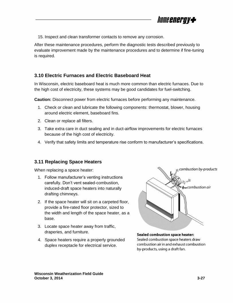
Duct Improvements to Solve Draft Problems
Consider the following duct and airflow improvements when attempt to improve worst-case
draft:
1. Seal/remove any return grilles in the CAZ.
2. Install a sealing filter cover.
3. Seal return-duct leaks in the CAZ, using the diagnostic workbook to guide duct-sealing
decision-making.
4. Isolate the furnace from its return registers by air-sealing.
5. Install make-up air to the CAZ. Open a nearby window, exterior door, or interior door to
observe whether the addition of make-up air will improve draft. If the open window or
door improves draft to an acceptable level, measure the size of the opening, and install
make-up air accordingly.
Table 3-7: Draft Problems and Solutions
Problem Possible Solutions
Adequate draft never established
Remove chimney blockage, seal chimney air leaks, or provide additional combus-tion air as necessary.
Blower activation weakens draft
Seal leaks in the furnace and in nearby return ducts. Isolate the furnace from nearby return registers.
Exhaust fans weakens draft
Provide make-up or combustion air if opening a door or window to outdoors strengthens draft during testing.
Closing interior doors during blower opera-tion weakens draft
Add return ducts, grills between rooms, or jumper ducts.

Wisconsin Weatherization Field Guide October 3, 2014 3-31
3.14 Combustion Air
A combustion-appliance zone (CAZ) is classified as either an unconfined space or as a
confined space. An unconfined space is a CAZ connected to enough building air leakage
to provide combustion air. A confined space is a CAZ with sheeted walls and ceiling and a
closed door that form an air barrier between the appliance and other indoor spaces.
Table 3-8: CFM Air Requirements for Combustion Furnaces or Boilers
Appliance Combustion
Air (cfm) Dilution Air
(cfm)
Conventional Oil 38 195
Flame-Retention Oil 25 195
High-Efficiency Oil 22 -
Conventional Atmospheric Gas 30 143
Fan-Assisted Gas 26 -
Condensing Gas 17 -
Fireplace (no doors) 100-600 -
Airtight Wood Stove 10-50
A.C.S. Hayden, Residential Combustion Appliances: Venting and Indoor Air Quality Solid Fuels Encyclopedia
For confined spaces, the IFGC prescribes additional combustion air from outside the CAZ.
Combustion air is supplied to the combustion-appliance zone in four ways.
1. To an unconfined space through leaks within the building.
2. To a confined space through an intentional opening or openings between the CAZ and
other indoor areas where air transfers in to replenish combustion air.
3. To a confined space through an intentional opening or openings between the CAZ and
outdoors or ventilated intermediate zones like attics and crawl spaces.
4. Directly from the outdoors to the confined or airtight CAZ through a duct. Appliances
with their own direct combustion-air ducts are called sealed-combustion or direct-
vent appliances.

Wisconsin Weatherization Field Guide October 3, 2014 3-32
3.14.1 Unconfined-Space Combustion Air
Combustion appliances located in most basements, attics, and crawl spaces get adequate
combustion air from leaks in the building shell. Even when a combustion appliance is
located within the home’s living space, it usually gets adequate combustion air from air
leaks, unless the house is airtight or the combustion zone is depressurized.
3.14.2 Confined-Space Combustion Air
A confined space is defined by the IFGC as a room that contains one or more combustion
appliances and which has less than 50 cubic feet of volume for every 1,000 BTUs per hour
(BTUh) of appliance input.
If a small mechanical room is connected to adjacent spaces through large air passages like
floor-joist spaces, however, the CAZ may not need additional combustion air, even with
sheeted walls and a door separating it from other indoor spaces. The extent of the
connection between the CAZ and other spaces can be confirmed by worst-case draft testing
or blower-door testing.
On the other hand, if the home is unusually airtight, the CAZ may not be able to obtain
adequate combustion air, even when the CAZ is larger than the minimum confined-space
room volume, defined above.
In confined spaces or airtight homes where outdoor combustion air is needed, the best
strategy is a single vent opening installed as low in the CAZ as is practical. A combustion-air
vent into an attic may depressurize the combustion zone or dump warm, moist air into the
attic. Instead, connect the combustion zone directly to the outdoors or to a ventilated crawl
space through a single low vent, if possible.
Choose an outdoor location that
is sheltered, where the wall
containing the vent isn’t parallel
to prevailing winds. Wind
blowing parallel to an exterior
wall or at a right angle to the
vent opening tends to de-
pressurize both the opening and
the CAZ connected to it.
Indoors, locate combustion air
vents away from water pipes to
prevent the pipes from freezing.

Wisconsin Weatherization Field Guide October 3, 2014 3-33
3.14.3 Net Free Area
Net free area is the surface area of venting that remains open after subtracting for the
blocking effect of louvers and grilles. Metal grilles and louvers are assumed to reduce the
size of the vent opening to 75 percent of the original surface area. Wooden grilles and
louvers are more restrictive, and they are assumed to reduce the net free area to 25 percent
of the original surface area.
Manufacturers often provide specifications about the net free area through their grilles and
louvers. When this information is available, use it to calculate the size of opening required to
provide the net free area necessary. When these specifications are not available, use the
assumptions listed above.
For example, calculate a 10-inch by 10-inch opening (100 square inches) with a metal grille
attached as having 75 square inches of net free area. With a wooden louver installed, to
calculate the same opening use 25 square inches of net free area.
When sizing vent openings always account for the reduction in net free area that will occur
due to the installation of grilles and louvers.
3.14.4 Sizing Combustion-Air Openings
Table 3-9 summarizes the required ratios of combustion-air net free area to appliance input
(BTUh).
Here is an example of sizing
two direct combustion-air
openings to adjacent indoor
space: The furnace and
water heater are located in a
confined space. The furnace
has an input rating of
100,000 BTUh. The water
heater has an input rating of
50,000 BTUh. Combined, the
two appliances have an input
rating of 150,000 BTUh. So,
each opening must have at least 150 square inches of net free area of venting between the
mechanical room and adjacent indoor space (150,000 ÷ 1,000 = 150). There are two
openings, so the CAZ will have a total of 300 square inches of net free area of venting.
Table 3-9: Combustion Air Openings: Location and Size
Location Dimensions
Two direct openings to adjacent indoor space
Minimum area each: 100 in2
1 in2 per 1000 Btuh each
Combined rooms volumes must be ≥S 50 ft
3/1000 Btuh
Two direct openings or vertical ducts to outdoors
Each vent should have 1 in2 for each 4000
Btuh
Two horizontal ducts to outdoors
Each vent should have 1 in2 for each 2000
Btuh
Single direct or ducted vent to outdoors
Single vent should have 1 in2 for each
3000 Btuh
From the International Fuel Gas Code (IFCG)

Wisconsin Weatherization Field Guide October 3, 2014 3-34
If the same CAZ were ducted to the outdoors with a single opening, the requirement for net
free area of venting would decrease to 50 square inches (150,000 ÷ 3,000 = 50 sq. in.).
When installing two combustion-air openings, the IFGC usually requires that one opening
commences 12 inches from the ceiling and one opening 12 inches from the floor. See IFGC
2012, Section 304.5 for a full breakdown of combustion-air requirements.
3.15 Thermostats
Set the thermostat’s heat anticipator to the amperage measured in the control circuit, or
follow the thermostat-manufacturer’s instructions for adjusting cycle length.
3.15.1 Programmable Thermostats
A programmable thermostat may be a big energy saver if the occupants understand how to
operate the thermostat. If the existing thermostat will be replaced as a part of the
weatherization work, discuss this option with the occupant. If the occupant is willing to use a
programmable thermostat, proceed with the installation. Educate the occupant on the use of
the thermostat, and leave a copy of manufacturer’s directions with them.

Wisconsin Weatherization Field Guide October 3, 2014 3-35
Final inspection and Quality Assurance Standards
Heating system work shall meet the following requirements.
Required Outcomes
Replacements Clean and Tune
All
Fu
els
&
Typ
es
1. The carbon monoxide concentration
in the undiluted flue gas does not
exceed 100 ppm as-measured or 200
ppm air-free, unless manufacturer’s
specification limit is higher.
1. The carbon monoxide concentration
in the undiluted flue gas does not
exceed 100 ppm as-measured or 200
ppm air-free, unless manufacturer’s
specification limit is higher.
Ga
s
Sy
ste
ms
2. Test and set the gas pressure within
the manufacturer’s specifications.
2. Test and set the gas pressure within
the manufacturer’s specifications
Oil
Sy
ste
ms
3. The smoke test: ≤ 1 for flame
retention burner systems and ≤ 2 for
non-flame retention burner systems
using a smoke-spot scale
3. The smoke test: ≤1 for flame
retention burner systems and ≤2 for
non-flame retention burner systems
using a smoke-spot scale.
Fo
rce
d-
Air
4. The temperature rise is within the
manufacturer’s specification.
4. The temperature rise is within the
manufacturer’s specification.
All B
oile
rs
5. O2 and CO (or CO2) values are within
manufacturer’s specified range.
6. Non-condensing boiler: The stack
temperature is at least 300 degrees to
minimize condensation in the
chimney.
5. O2 and CO (or CO2) values are within
manufacturer’s specified range.
6. Non-condensing boiler: The stack
temperature is at least 300 degrees to
minimize condensation in the
chimney.
≥ 9
0%
Bo
ile
rs 7. Outside air temperature sensor is
installed on a north-facing exterior
wall.
8. Heating curve is programmed in line
with the dwelling’s heat loss and
radiation capacity.
7. Outside air temperature sensor is
installed on a north-facing exterior
wall.
8. Heating curve is programmed in line
with the dwelling’s heat loss and
radiation capacity.

Wisconsin Weatherization Field Guide October 3, 2014 3-36
Heating Systems - General
1. Heating System Check List is complete, in file;
2. Condensate:
a. Properly drains and is secured to floor drain
b. Does not present a tripping hazard.
c. Pump installed only when needed.
3. No fuel leaks.
4. Oil systems have a new oil filter.
5. There are no pre-existing unvented space heaters remaining in place.
Required Testing
Replacements Clean and Tune
All
Fu
els
& T
yp
es
1. Measure the steady-state efficiency
(SSE).
1. Measure the steady-state efficiency
(SSE).
2. Measure oxygen (O2) levels. See
Table 3-2, Typical Ranges for Gas-
Burning Equipment.
2. Measure oxygen (O2) levels. See
Table 3-2, Typical Ranges for Gas-
Burning Equipment.
3. Measure the stack temperature (T-
Stack).
3. Measure the stack temperature (T-
Stack).
Fo
rce
d-A
ir
4. Measure the air flow of the furnace
air handler. Use a flow plate or the
manufacturer’s fan-flow tables to
calculate air flow.
4. Measure the air flow of the furnace air
handler. Use a flow plate or the
manufacturer’s fan-flow tables to
calculate air flow.
All B
oile
rs
5. Measure the supply and return water
temperatures.
5. Measure the supply and return water
temperatures.

Wisconsin Weatherization Field Guide October 3, 2014 3-37
New Heating Systems
1. Heating system is properly sized and adequately heats the building.
a. Sizing calculation is in the customer file that accurately reflects the heat loss of
the post-weatherization building.
b. Distribution system is adequate for the properly sized furnace.
2. Heating system has proper venting.
a. Meets manufacturer’s and code requirements.
b. Proper clearances from windows and doors
3. System is raised off of the floor by durable materials.
a. For basements with known water problems, the height is based on typical high
water marks noted in the CAZ or based on customer input.
4. Heating system equipment meets specification requirements.
5. Building permit obtained as required.
6. Installation meets code requirements.
7. System is on a dedicated electrical circuit.
a. Service disconnect is present or within line-of-sight at service panel.
b. Circuit is properly sized or a fuse or breaker is installed to protect the system.
8. The warranty and/or manual booklet is posted on or near the furnace.
9. Installed wood systems or stoves comply with NFPA 211 or EPA (per label).
Forced-Air Distribution
1. Filter/compartment
a. is properly sealed, tight cover fit, and the filter seals to the filter rack.
b. allows for easy filter replacement.
c. Filter is MERV 6 or better.
d. 1 cleanable filter or 6 disposable filters included.
2. Distribution within the CAZ and living areas are sealed based on worst-case
depressurization testing. The distribution system does not excessively depressurize
the CAZ, (>1 Pascal, based on warnings in the diagnostic workbook when Category I
appliances are present) circulate unhealthy air into the living area, and does provide
adequate heat and return air to the living areas.

Wisconsin Weatherization Field Guide October 3, 2014 3-38
3. Supplies heat to the assigned rooms in an efficient and sufficient manner
4. New supply and return ducts are the proper size for efficient operation of the heating
system.
5. Duct joints are properly attached.
6. Metal ducts were sealed with a UL181 rated material.
7. Distribution work in unheated areas is insulated to minimum of R-10.
8. Insulation meets material specifications and is not compressed.
9. Fiberglass insulation is installed with mechanical fasteners.
10. Registers are properly functioning for their intended purpose.
11. There are no return grills in the CAZ.
12. New supply ducts have dampers.
13. Mobile home return air system is centralized through living space
14. Back-draft dampers have been installed between a wood furnace plenum and
another forced air system.
Boilers
1. Boiler size is properly calculated and includes domestic hot water when applicable.
2. Existing radiators and other terminal devices are the appropriate size and quantity for
the spaces they heat.
3. Heating System Check List is complete, in file;
4. Replacement units must be rated for the application.
5. The existing feed water and distribution systems was modified as necessary to work
properly with a new boiler, including boiler controls, auto fill valve, zone valve,
expansion tank is present and functioning as designed, and air temperature sensor is
installed.
6. Existing boiler or distribution was properly adjusted or modified.
7. Radiators were bled and there no air is in the system.
8. Pressure relief valve has been documented as opened; closes without leaking,
9. (3 and 4 unit buildings only) Boiler registration number is posted with current state
certified inspection.

Wisconsin Weatherization Field Guide October 3, 2014 3-39
Hot-Water Space-Heating Distribution
1. Pipes are insulated in unheated areas.
2. Seams are tightly fitted and secured.
3. No leaks in the system.
Thermostats
1. Installed thermostat functions properly with the installed heating system and meets
household needs.
2. Customer has been educated and understands how to operate programmable
thermostat.
3. Thermostat is in a location that allows the heating system to operate properly and
heat the space.
4. Thermostat is installed on an interior wall.
Additional Considerations
Under certain circumstances the following items may be necessary to verify that other tests
results are correct or for troubleshooting various problems.
1. Air flow through the flow meter is consistent with flow rate listed in Table 3.1 and the
manufacturer’s fan tables.

Wisconsin Weatherization Field Guide October 3, 2014 3-40
Additional Tests
Replacements Clean and Tune
All
Fu
els
&
Typ
es
1. Confirm that excess air (EA) is
adequate.
1. Confirm that excess air (EA) is
adequate.
Nat
Ga
s
Sy
ste
ms 2. Measure the input by “clocking
the meter” to determine the
input of a natural gas appliance.
Input is typically within 10% of
the appliance rating.
2. Measure the input by “clocking the
meter” to determine the input of a
natural gas appliance. Input is
typically within 10% of the appliance
rating.
Oil
Sy
ste
ms
3. Check oil pump pressure. 3. Check oil pump pressure.
Fo
rce
d
-Air
4. Measure external static pressure (ESP).
4. Measure external static pressure
(ESP).