CHAPTER 3 504.3 ELECTRICAL MEASURING INSTRUMENTS...Electrical measuring instruments are devices used...
12
BUILDING SERVICES ENGINEERING DEPARTMENT, MKJB ELECTRICAL AND ELECTRONICS APPLICATIONS, DIP 1 PREKA AKLIKA AK BELON 2013/2014 1 CHAPTER 3 504.3 ELECTRICAL MEASURING INSTRUMENTS By the end of this chapter, students should be able to: Identify the various types of electrical measuring instrument and their applications. Describe the correct procedures of using electrical measuring instrument. Perform tests or measure for some of the electrical instruments.
Transcript of CHAPTER 3 504.3 ELECTRICAL MEASURING INSTRUMENTS...Electrical measuring instruments are devices used...

BUILDING SERVICES ENGINEERING DEPARTMENT, MKJB ELECTRICAL AND ELECTRONICS APPLICATIONS, DIP 1
PREKA AKLIKA AK BELON 2013/2014
1
CHAPTER 3
504.3
ELECTRICAL MEASURING INSTRUMENTS
By the end of this chapter, students should be able to:
Identify the various types of electrical measuring instrument
and their applications.
Describe the correct procedures of using electrical
measuring instrument.
Perform tests or measure for some of the electrical
instruments.
BUILDING SERVICES ENGINEERING DEPARTMENT, MKJB ELECTRICAL AND ELECTRONICS APPLICATIONS, DIP 1
PREKA AKLIKA AK BELON 2013/2014
2
504.3.1 ELECTRICAL MEASURING INSTRUMENTS
Electrical measuring instruments are devices used to measure electrical quantities such as electric
current, voltage, resistance, electrical power and energy.
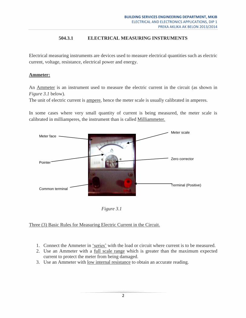
Ammeter:
An Ammeter is an instrument used to measure the electric current in the circuit (as shown in
Figure 3.1 below).
The unit of electric current is ampere, hence the meter scale is usually calibrated in amperes.
In some cases where very small quantity of current is being measured, the meter scale is
calibrated in milliamperes, the instrument than is called Milliammeter.
Figure 3.1
Three (3) Basic Rules for Measuring Electric Current in the Circuit.
1. Connect the Ammeter in ‘series’ with the load or circuit where current is to be measured.
2. Use an Ammeter with a full scale range which is greater than the maximum expected
current to protect the meter from being damaged.
3. Use an Ammeter with low internal resistance to obtain an accurate reading.
Meter face
Pointer
Common terminal
Meter scale
Zero corrector
Terminal (Positive)
BUILDING SERVICES ENGINEERING DEPARTMENT, MKJB ELECTRICAL AND ELECTRONICS APPLICATIONS, DIP 1
PREKA AKLIKA AK BELON 2013/2014
3
There are two general types of Ammeter, namely;
1. D.C. Ammeter. 2. A.C. Ammeter.
Nowadays, AC-DC Ammeters are also available.
Connection of Ammeters:
Ammeters are always in series with the load. Failure to do this may result in permanent damage
to instruments.
You also must pay attention to polarity (positive and negative terminals) when using a DC
Ammeter in a D.C circuit. The positive terminal of a D.C ammeter must be connected with
reference to the positive polarity of the supply (battery).
In the case of A.C. Ammeter the polarity or terminal connections can be interchanged.
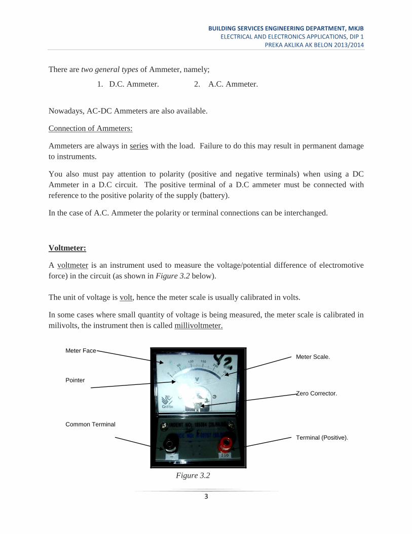
Voltmeter:
A voltmeter is an instrument used to measure the voltage/potential difference of electromotive
force) in the circuit (as shown in Figure 3.2 below).
The unit of voltage is volt, hence the meter scale is usually calibrated in volts.
In some cases where small quantity of voltage is being measured, the meter scale is calibrated in
milivolts, the instrument then is called millivoltmeter.
Figure 3.2
Meter Face
Pointer
Common Terminal
Meter Scale.
Zero Corrector.
Terminal (Positive).
BUILDING SERVICES ENGINEERING DEPARTMENT, MKJB ELECTRICAL AND ELECTRONICS APPLICATIONS, DIP 1
PREKA AKLIKA AK BELON 2013/2014
4
Three (3) Basic Rules for Measuring the Voltage in the Circuit.
1. Connect the voltmeter in ‘parallel’ with the load or circuit where voltage is to be
measured.
2. Use a Voltmeter with a full-scale range which is greater than the maximum expected
voltage to protect the meter from being damaged.
3. Use a voltmeter with high input impedance as compared to the circuit resistance.
The voltmeter is a high impedance device, so any attempt to connect it in series will greatly
increases circuit resistance, causing improper operation.
There are two general types of voltmeter, namely;
a. D.C Voltmeter and
b. A.C. Voltmeter.
Nowadays, AC-DC Voltmeters are also available. Similar to D.C Ammeter, D.C. Voltmeter
terminals must be connected in correct polarities. In the case of A.C. Voltmeter the polarity or
terminal connections can be interchanged.
Ohmmeter:
An Ohmmeter is an instrument used for measuring electrical resistance.
The unit of resistance is ohm, hence, the meter scale is usually calibrated in ohms. In some cases
where very large quantity of resistance is being measured, the meter scale is calibrated in Kilo-
Ohms (K).
Another version of instrument similar to ohmmeter which is calibrated in much higher scale,
mega-ohms (M) is known as a ‘Megger’. A Megger is an electrical instrument used to
measure the insulation resistance of a cable.
Three (3) Functions of the Ohmmeter.
1. For measuring resistance.
2. For continuity testing.
3. For polarity testing.

BUILDING SERVICES ENGINEERING DEPARTMENT, MKJB ELECTRICAL AND ELECTRONICS APPLICATIONS, DIP 1
PREKA AKLIKA AK BELON 2013/2014
5
The resistance of a resistor can be measured by:
1. Ohmmeter or multimeter (VOM).
2. Ammeter and Voltmeter method (Ohm’s law).
Multimeter:
Figure 3.3
Multimeter is a single meter which is capable of measuring two or more electrical quantities such
as resistance, voltage and current (a.c. and d.c.) as shown in Figure 3.3 above.
It is a multi-purpose meter which can be used as; Voltmeter, Ohmmeter and Milliammeter
(VOM).
Pointer
Zero corrector.
Output Terminal
Range selector
Com socket.
Scale meter
0 ADJ
Range and function
Terminal (Positive)
BUILDING SERVICES ENGINEERING DEPARTMENT, MKJB ELECTRICAL AND ELECTRONICS APPLICATIONS, DIP 1
PREKA AKLIKA AK BELON 2013/2014
6
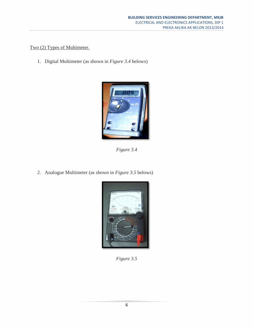
Two (2) Types of Multimeter.
1. Digital Multimeter (as shown in Figure 3.4 belows)
Figure 3.4
2. Analogue Multimeter (as shown in Figure 3.5 belows)
Figure 3.5

BUILDING SERVICES ENGINEERING DEPARTMENT, MKJB ELECTRICAL AND ELECTRONICS APPLICATIONS, DIP 1
PREKA AKLIKA AK BELON 2013/2014
7
In analogue multimeter, there are three parts that is important to understand, they are;
a. Function.
b. Range.
c. Scale.
a. Function – it is the types of quantity to be measured. Eg. Voltage in a.c./d.c. volts,
Current in a.c./d.c. ampere and resistance in Ohm.
b. Range - it is the limited values for each function for examples the expected values of the
circuit to be measured is 20V d.c., then use the range of 25V and the function of DCV.
c. Scale – It is the place where we read the values the meter produce. Scale can only be
found in analogue type of meter.
How to use multimeter to read the resistance value;
Procedures:
1. Set the Range Selector to the appropriate range position. The ranges are:
a. R x 1
b. R X 10
c. R x 100
d. R x 1K
e. R x 10K
If the resistance is not known, start from the highest range setting.
2. Check if the Pointer rests on the infinity mark (). If not adjust the movement of the
pointer with a small screwdriver.
3. Connect the test leads (test probes) together, short circuiting them. Check if the pointer
rests on 0. If not, adjust the 0 ADJ.
If the pointer cannot be zeroed the internal battery requires replacement.
BUILDING SERVICES ENGINEERING DEPARTMENT, MKJB ELECTRICAL AND ELECTRONICS APPLICATIONS, DIP 1
PREKA AKLIKA AK BELON 2013/2014
8
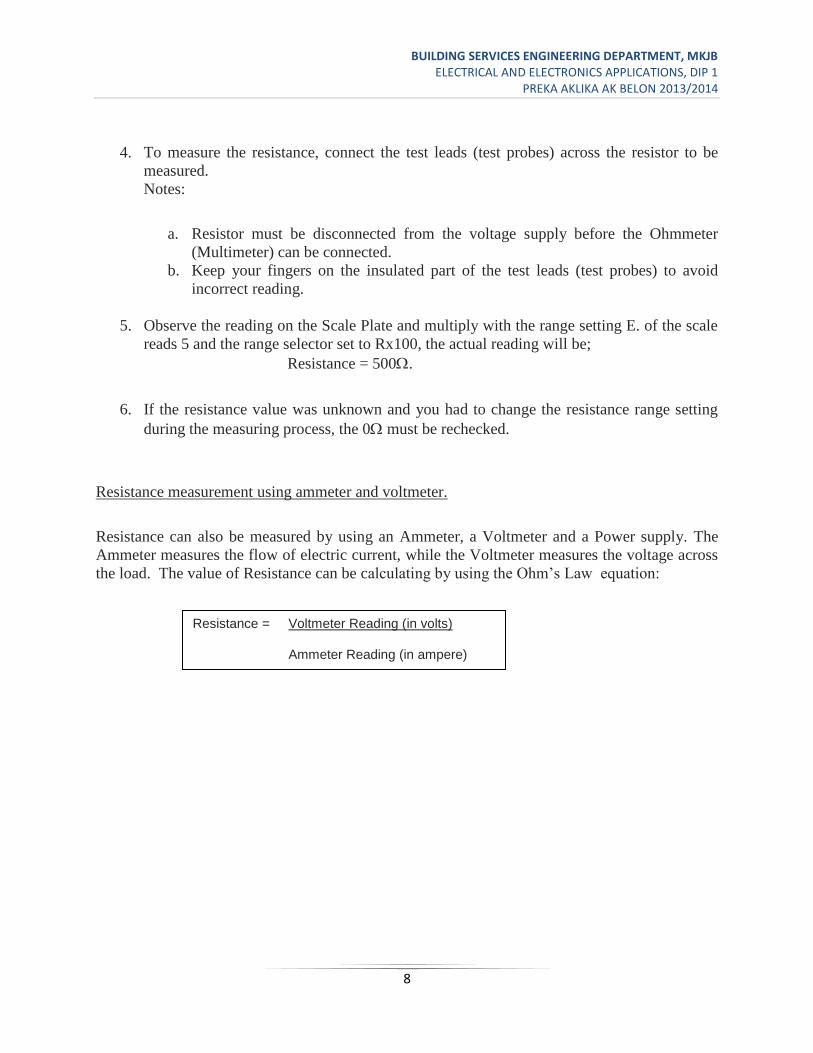
4. To measure the resistance, connect the test leads (test probes) across the resistor to be
measured.
Notes:
a. Resistor must be disconnected from the voltage supply before the Ohmmeter
(Multimeter) can be connected.
b. Keep your fingers on the insulated part of the test leads (test probes) to avoid
incorrect reading.
5. Observe the reading on the Scale Plate and multiply with the range setting E. of the scale
reads 5 and the range selector set to Rx100, the actual reading will be;
Resistance = 500.
6. If the resistance value was unknown and you had to change the resistance range setting
during the measuring process, the 0 must be rechecked.
Resistance measurement using ammeter and voltmeter.
Resistance can also be measured by using an Ammeter, a Voltmeter and a Power supply. The
Ammeter measures the flow of electric current, while the Voltmeter measures the voltage across
the load. The value of Resistance can be calculating by using the Ohm’s Law equation:
Resistance = Voltmeter Reading (in volts)
Ammeter Reading (in ampere)
BUILDING SERVICES ENGINEERING DEPARTMENT, MKJB ELECTRICAL AND ELECTRONICS APPLICATIONS, DIP 1
PREKA AKLIKA AK BELON 2013/2014
9
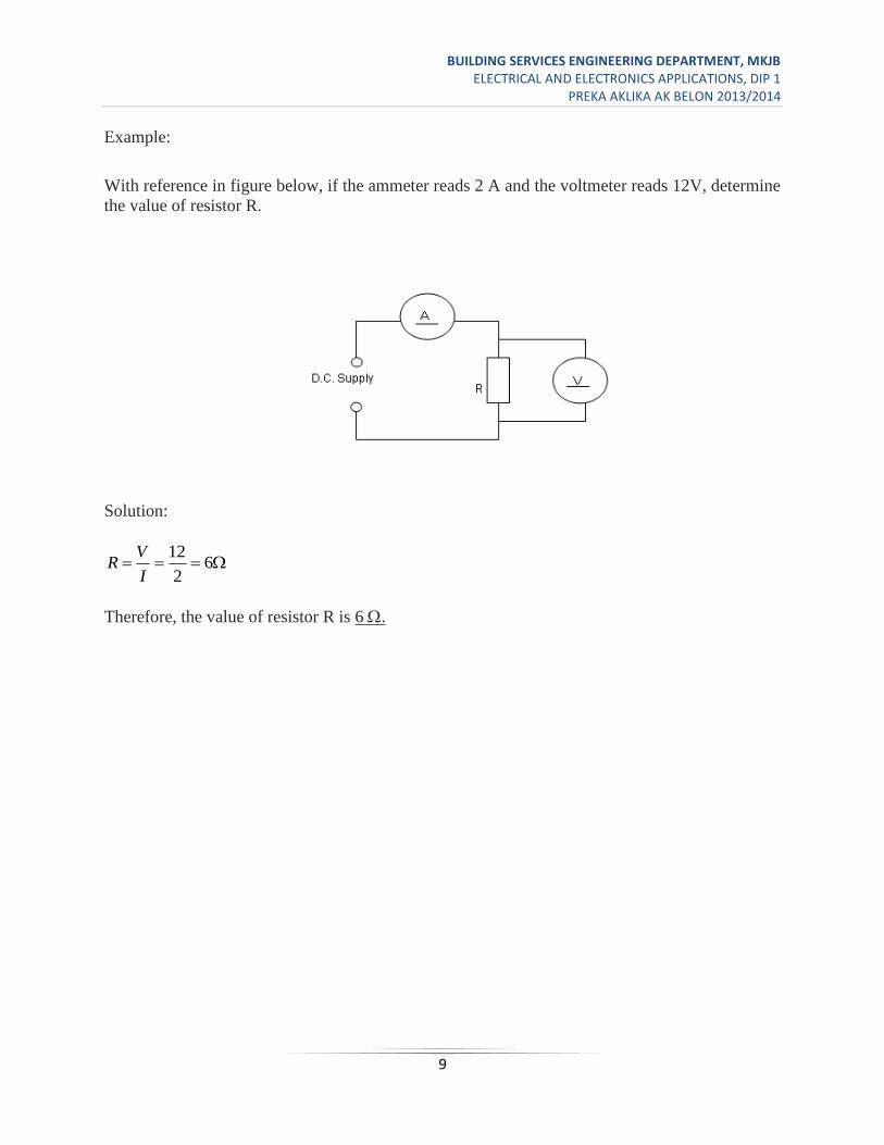
Example:
With reference in figure below, if the ammeter reads 2 A and the voltmeter reads 12V, determine
the value of resistor R.
Solution:
62
12
I
VR
Therefore, the value of resistor R is 6 .
BUILDING SERVICES ENGINEERING DEPARTMENT, MKJB ELECTRICAL AND ELECTRONICS APPLICATIONS, DIP 1
PREKA AKLIKA AK BELON 2013/2014
10
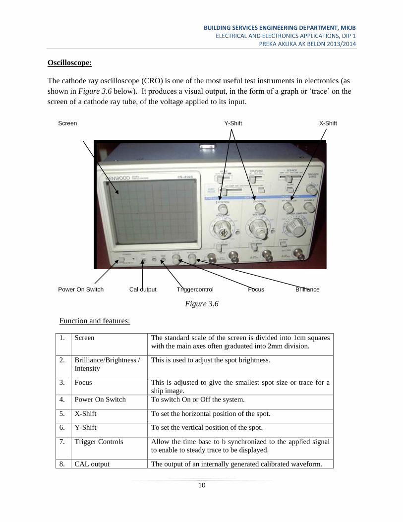
Oscilloscope:
The cathode ray oscilloscope (CRO) is one of the most useful test instruments in electronics (as
shown in Figure 3.6 below). It produces a visual output, in the form of a graph or ‘trace’ on the
screen of a cathode ray tube, of the voltage applied to its input.
Figure 3.6
Function and features:
1. Screen The standard scale of the screen is divided into 1cm squares
with the main axes often graduated into 2mm division.
2. Brilliance/Brightness /
Intensity
This is used to adjust the spot brightness.
3. Focus This is adjusted to give the smallest spot size or trace for a
ship image.
4. Power On Switch To switch On or Off the system.
5. X-Shift To set the horizontal position of the spot.
6. Y-Shift To set the vertical position of the spot.
7. Trigger Controls Allow the time base to b synchronized to the applied signal
to enable to steady trace to be displayed.
8. CAL output The output of an internally generated calibrated waveform.
Screen Y-Shift X-Shift
Power On Switch Cal output Triggercontrol Focus Brilliance
BUILDING SERVICES ENGINEERING DEPARTMENT, MKJB ELECTRICAL AND ELECTRONICS APPLICATIONS, DIP 1
PREKA AKLIKA AK BELON 2013/2014
11
Uses of CRO
CRO can be used to trace waveform measurements of amplitude periodic time for a sinusoidal
voltage of current, as well as displaying waveform.
a. Voltage measurement
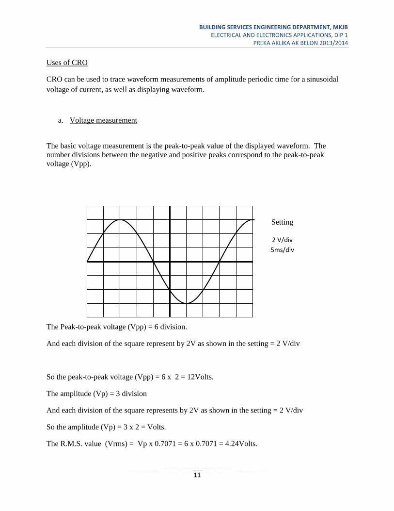
The basic voltage measurement is the peak-to-peak value of the displayed waveform. The
number divisions between the negative and positive peaks correspond to the peak-to-peak
voltage (Vpp).
The Peak-to-peak voltage (Vpp) = 6 division.
And each division of the square represent by 2V as shown in the setting = 2 V/div
So the peak-to-peak voltage (Vpp) = 6 x 2 = 12Volts.
The amplitude (Vp) = 3 division
And each division of the square represents by 2V as shown in the setting = 2 V/div
So the amplitude (Vp) = 3 x 2 = Volts.
The R.M.S. value (Vrms) = Vp x 0.7071 = 6 x 0.7071 = 4.24Volts.
Setting
2 V/div
5ms/div
BUILDING SERVICES ENGINEERING DEPARTMENT, MKJB ELECTRICAL AND ELECTRONICS APPLICATIONS, DIP 1
PREKA AKLIKA AK BELON 2013/2014
12
b. Time and frequency measurement
The number horizontal divisions for one complete cycle of the display represent the period of the
waveform shown in figure above.
Period (t) = x-axis = 8 division.
The setting shows that for each division it is represented by 5msec.
So the time period (t) = 8 x 5m = 40msec
The frequency is the number of cycle it takes in one second.
Frequency (f) = )(251040
113
HzHertzt
Function Generator:
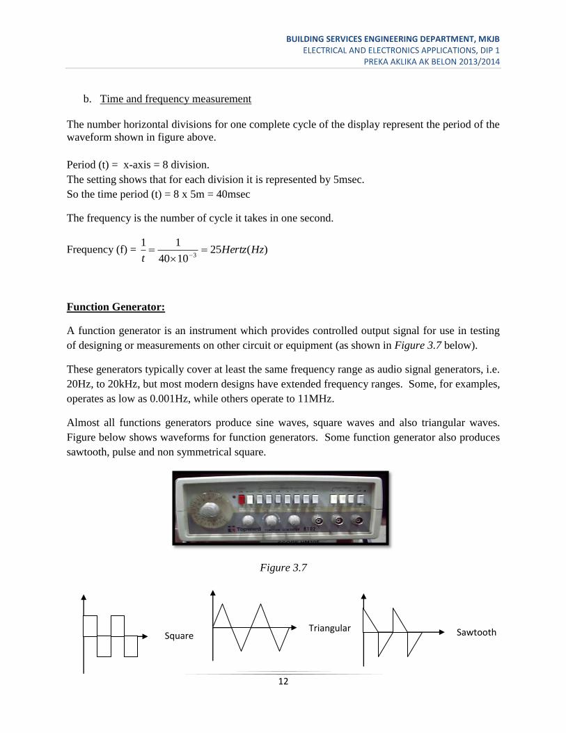
A function generator is an instrument which provides controlled output signal for use in testing
of designing or measurements on other circuit or equipment (as shown in Figure 3.7 below).
These generators typically cover at least the same frequency range as audio signal generators, i.e.
20Hz, to 20kHz, but most modern designs have extended frequency ranges. Some, for examples,
operates as low as 0.001Hz, while others operate to 11MHz.
Almost all functions generators produce sine waves, square waves and also triangular waves.
Figure below shows waveforms for function generators. Some function generator also produces
sawtooth, pulse and non symmetrical square.
Figure 3.7
Square
wave
Triangular
wave Sawtooth
wave