
ELECTRICAL SCIENCE Module 14 Test Instruments & Measuring ... Textbooks/11... · OTHER ELECTRICAL...
35
DOE Fundamentals ELECTRICAL SCIENCE Module 14 Test Instruments & Measuring Devices
Transcript of ELECTRICAL SCIENCE Module 14 Test Instruments & Measuring ... Textbooks/11... · OTHER ELECTRICAL...

DOE Fundamentals
ELECTRICAL SCIENCE
Module 14
Test Instruments & Measuring Devices

Electrical Science Test Instruments & Measuring Devices
i
TABLE OF CONTENTS
Table of Co nte nts TABLE OF CONTENTS ................................................................................................... i
LIST OF FIGURES .......................................................................................................... iii
LIST OF TABLES ............................................................................................................iv
REFERENCES ................................................................................................................ v
OBJECTIVES ..................................................................................................................vi
METER MOVEMENTS .................................................................................................... 1
D'Arsonval Movement .................................................................................................. 1
Electrodynamometer Movement .................................................................................. 2
Moving Iron Vane Movement ....................................................................................... 3
Summary ..................................................................................................................... 4
VOLTMETERS ................................................................................................................ 5
Voltmeter ..................................................................................................................... 5
Summary ..................................................................................................................... 9
AMMETERS .................................................................................................................. 10
Ammeter .................................................................................................................... 10
Summary ................................................................................................................... 14
OHM METERS .............................................................................................................. 15
Ohm Meter ................................................................................................................. 15
Summary ................................................................................................................... 18
WATTMETERS ............................................................................................................. 19
Wattmeter .................................................................................................................. 19
Three-Phase Wattmeter ............................................................................................ 20
Summary ................................................................................................................... 21
OTHER ELECTRICAL MEASURING DEVICES ........................................................... 22
Ampere-Hour Meter ................................................................................................... 22
Power Factor Meter ................................................................................................... 23
Ground Detector ........................................................................................................ 23
Synchroscope ............................................................................................................ 25
Summary ................................................................................................................... 25
Electrical Science Test Instruments & Measuring Devices
ii
TEST EQUIPMENT ....................................................................................................... 26
Multimeter .................................................................................................................. 26
Megger ...................................................................................................................... 26
Summary ................................................................................................................... 27

Electrical Science Test Instruments & Measuring Devices
iii
LIST OF FIGURES
Figure 1 D'Arsonval Meter Movement .................................................................... 1
Figure 2 Electrodynamometer Movement .............................................................. 2
Figure 3 Moving Iron Vane Meter Movement ......................................................... 3
Figure 4 Simple DC Voltmeter ............................................................................... 5
Figure 5 Measuring Circuit Voltage ........................................................................ 8
Figure 6 Ammeter ................................................................................................ 10
Figure 7 Ammeter Accuracy ................................................................................. 11
Figure 8 Ammeter with Shunt ............................................................................... 13
Figure 9 Simple Ohm Meter Circuit ...................................................................... 15
Figure 10 Ohm Meter Scale ................................................................................... 19
Figure 11 Wattmeter Schematic ............................................................................. 20
Figure 12 Wattmeters in Each Phase .................................................................... 21
Figure 13 Two Wattmeters to Measure 34 Power .................................................. 22
Figure 14 34 Power Factor Meter Schematic ......................................................... 24
Figure 15 Simple Ohm Meter Ground Detector ...................................................... 25
Figure 16 Ground Detector Lamp Circuit ............................................................... 26
Figure 17 Simple Megger Circuit Diagram ............................................................. 29

Electrical Science Test Instruments & Measuring Devices
iv
LIST OF TABLES
NONE

Electrical Science Test Instruments & Measuring Devices
v
REFERENCES
Gussow, Milton, Schaum's Outline of Basic Electricity, 2nd Edition, McGraw-Hill.
Academic Program for Nuclear Power Plant Personnel, Volume II, Columbia,
MD: General Physics Corporation, Library of Congress Card #A 326517, 1982.
Nasar and Unnewehr, Electromechanics and Electric Machines, 2nd Edition, John
Wiley and Sons.
Nooger and Neville Inc., Van Valkenburgh, Basic Electricity, Vol. 5, Hayden Book
Company.
Lister, Eugene C., Electric Circuits and Machines, 5th Edition, McGraw-Hill.
Croft, Hartwell, and Summers, American Electricians’ Handbook, 16th Edition,
McGraw-Hill.
Mason, C. Russell, The Art and Science of Protective Relaying, John Wiley and
Sons.
Mileaf, Harry, Electricity One - Seven, Revised 2nd Edition, Prentice Hall.
Kidwell, Walter, Electrical Instruments and Measurements, McGraw-Hill.
Buban and Schmitt, Understanding Electricity and Electronics, 3rd Edition,
McGraw-Hill.

Electrical Science Test Instruments & Measuring Devices
vi
OBJECTIVES
TERMINAL OBJECTIVE
1.0 Given a piece of test equipment or measuring device, DESCRIBE the use of that
piece of electrical equipment, to include the meter movement, electrical
parameter measurement, and connection of the device to a circuit.
ENABLING OBJECTIVES
1.1 EXPLAIN the following meter movements:
a. D'Arsonval
b. Electrodynamometer
c. Moving iron vane
1.2 STATE the electrical parameters measured by each of the following in-place
measuring devices:
a. Voltmeter
b. Ammeter
c. Ohm meter
d. Wattmeter
e. Ampere-hour meter
f. Power factor meter
g. Ground detector
h. Synchroscope
1.3 EXPLAIN how the following electrical test equipment and measuring devices are
connected to a circuit:
a. Voltmeter
b. Ammeter
c. Ohm meter
d. Wattmeter
e. Ampere-hour meter
f. Power factor meter
g. Ground detector
h. Synchroscope
i. Megger

Electrical Science Test Instruments & Measuring Devices
vii
1.4 STATE the electrical parameters measured by each of the following test
instruments:
a. Multimeter
b. Megger

Electrical Science Test Instruments & Measuring Devices Meter Movements
1
METER MOVEMENTS
There are three basic meter movements utilized in electrical meters:
D'Arsonval, electrodynamometer, and the moving iron vane. Some meter
movements can be used for both AC or DC measurements, but in general,
each meter movement is best suited for a particular type.
EO 1.1 EXPLAIN the following meter movements:
a. D'Arsonval
b. Electrodynamometer
c. Moving iron vane
D'Arsonval Movement
The most commonly used sensing mechanism used in DC ammeters, voltmeters, and
ohm meters is a current-sensing device called a D'Arsonval meter movement (Figure 1).
The D'Arsonval movement is a DC moving coil-type movement in which an
electromagnetic core is suspended between the poles of a permanent magnet.
The current measured is directed through
the coils of the electromagnet so that the
magnetic field produced by the current
opposes the field of the permanent
magnet and causes rotation of the core.
The core is restrained by springs so that
the needle will deflect or move in
proportion to the current intensity. The
more current applied to the core, the
stronger the opposing field, and the larger
the deflection, up to the limit of the current
capacity of the coil. When the current is
interrupted, the opposing field collapses,
and the needle is returned to zero by the
restraining springs. The limit of the current
that can be applied to this type movement
is usually less than one milliampere.
Figure 1 D'Arsonval Meter Movement
Electrical Science Test Instruments & Measuring Devices Meter Movements
2
A common variation of the D'Arsonval movement is the Weston movement, which uses
essentially the same principle built to a more rugged construction by employing jeweled
supports for the core and employing a heavier winding in the electromagnet. Remember
that the D'Arsonval movement is a DC device and can only measure DC current or AC
current rectified to DC.
Electrodynamometer Movement
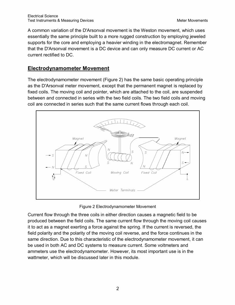
The electrodynamometer movement (Figure 2) has the same basic operating principle
as the D'Arsonval meter movement, except that the permanent magnet is replaced by
fixed coils. The moving coil and pointer, which are attached to the coil, are suspended
between and connected in series with the two field coils. The two field coils and moving
coil are connected in series such that the same current flows through each coil.
Figure 2 Electrodynamometer Movement
Current flow through the three coils in either direction causes a magnetic field to be
produced between the field coils. The same current flow through the moving coil causes
it to act as a magnet exerting a force against the spring. If the current is reversed, the
field polarity and the polarity of the moving coil reverse, and the force continues in the
same direction. Due to this characteristic of the electrodynamometer movement, it can
be used in both AC and DC systems to measure current. Some voltmeters and
ammeters use the electrodynamometer. However, its most important use is in the
wattmeter, which will be discussed later in this module.
Electrical Science Test Instruments & Measuring Devices Meter Movements
3
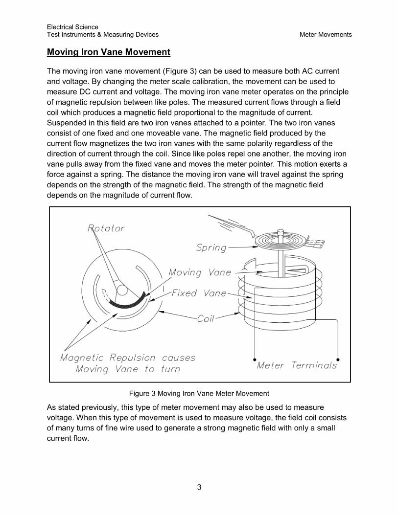
Moving Iron Vane Movement
The moving iron vane movement (Figure 3) can be used to measure both AC current
and voltage. By changing the meter scale calibration, the movement can be used to
measure DC current and voltage. The moving iron vane meter operates on the principle
of magnetic repulsion between like poles. The measured current flows through a field
coil which produces a magnetic field proportional to the magnitude of current.
Suspended in this field are two iron vanes attached to a pointer. The two iron vanes
consist of one fixed and one moveable vane. The magnetic field produced by the
current flow magnetizes the two iron vanes with the same polarity regardless of the
direction of current through the coil. Since like poles repel one another, the moving iron
vane pulls away from the fixed vane and moves the meter pointer. This motion exerts a
force against a spring. The distance the moving iron vane will travel against the spring
depends on the strength of the magnetic field. The strength of the magnetic field
depends on the magnitude of current flow.
Figure 3 Moving Iron Vane Meter Movement
As stated previously, this type of meter movement may also be used to measure
voltage. When this type of movement is used to measure voltage, the field coil consists
of many turns of fine wire used to generate a strong magnetic field with only a small
current flow.

Electrical Science Test Instruments & Measuring Devices Meter Movements
4
Summary
Meter movements are summarized below.
Meter Movement Summary
D'Arsonval - A DC moving coil movement where the moving coil is suspended
between the poles of a permanent magnet restrained by helical springs, and the
measured current flowing through the moving coil produces a torque on the
attached pointer proportional to the current.
Electrodynamometer - The moving coil and attached pointer are suspended
between and connected in series with the two stationary field coils so that the
same current flows through each. A measured current flowing through the three
coils in either direction causes a magnetic repulsion between the field coils and
the moving coil. The magnetic repulsion exerts a force against the spring and
provides a measurement of either DC or AC current.
Moving iron vane - The moving iron vane meter operates on the principle of
magnetic repulsion between like poles. The measured current flows through a
field coil which induces a like magnetic field into a fixed and moving vane
causing the moving vane to deflect a pointer in proportion to the current or
voltage applied to the coil.

Electrical Science Test Instruments & Measuring Devices Voltmeters
5
VOLTMETERS
Voltmeters are used extensively in industry where the surveillance of input
and/or output voltages is vital for plant operation.
EO 1.2 STATE the electrical parameters measured by each of the following
in-place measuring devices:
a. Voltmeter
EO 1.3 EXPLAIN how the following electrical test equipment and
measuring devices are connected to a circuit:
a. Voltmeter
Voltmeter
A simple DC voltmeter can be constructed by placing a resistor (Rs), called a multiplier,
in series with the ammeter meter movement, and marking the meter face to read
voltage (Figure 4). Voltmeters are connected in parallel with the load (RL) being
measured.
Figure 4 Simple DC Voltmeter
When constructing a voltmeter, the resistance of the multiplier must be determined to
measure the desired voltage. Equation (14-1) is a mathematical representation of the
voltmeter's multiplier resistance.

Electrical Science Test Instruments & Measuring Devices Voltmeters
6
V = ImRs + ImRm
ImRs = V - ImRm
(14-1)
where
V = voltage range desired
Im = meter current
Rm = meter resistance
Rs = multiplier resistance or series resistance
Example: A 2 mA meter movement with internal resistance of 25 ohms is to be
constructed as a voltmeter.
What value must the series resistance be to measure full scale voltage of
100 volts?
Solution:
Since Rm is negligibly low, then:
When a voltmeter is connected in a circuit, the voltmeter will draw current from that
circuit. This current causes a voltage drop across the resistance of the meter, which is
subtracted from the voltage being measured by the meter. This reduction in voltage is
known as the loading effect and can have a serious effect on measurement accuracy,
especially for low current circuits.
The accuracy of a voltmeter (Kv) is defined as the ratio of measured voltage when the
meter is in the circuit (Vw) to the voltage measured with the meter out of the circuit.
Equation (14-2) is a mathematical representation of the accuracy of a voltmeter, or true
voltage (Vo).
(14-2)

Electrical Science Test Instruments & Measuring Devices Voltmeters
7
Meter accuracy can also be determined by comparing the relationship between the
input and circuit resistances using Ohm's Law as described below.
where
Im = meter current
Vo = true voltage
R0 = circuit resistance
Rin = input resistance of the voltmeter
Kw = indicated voltage
Kv = meter accuracy
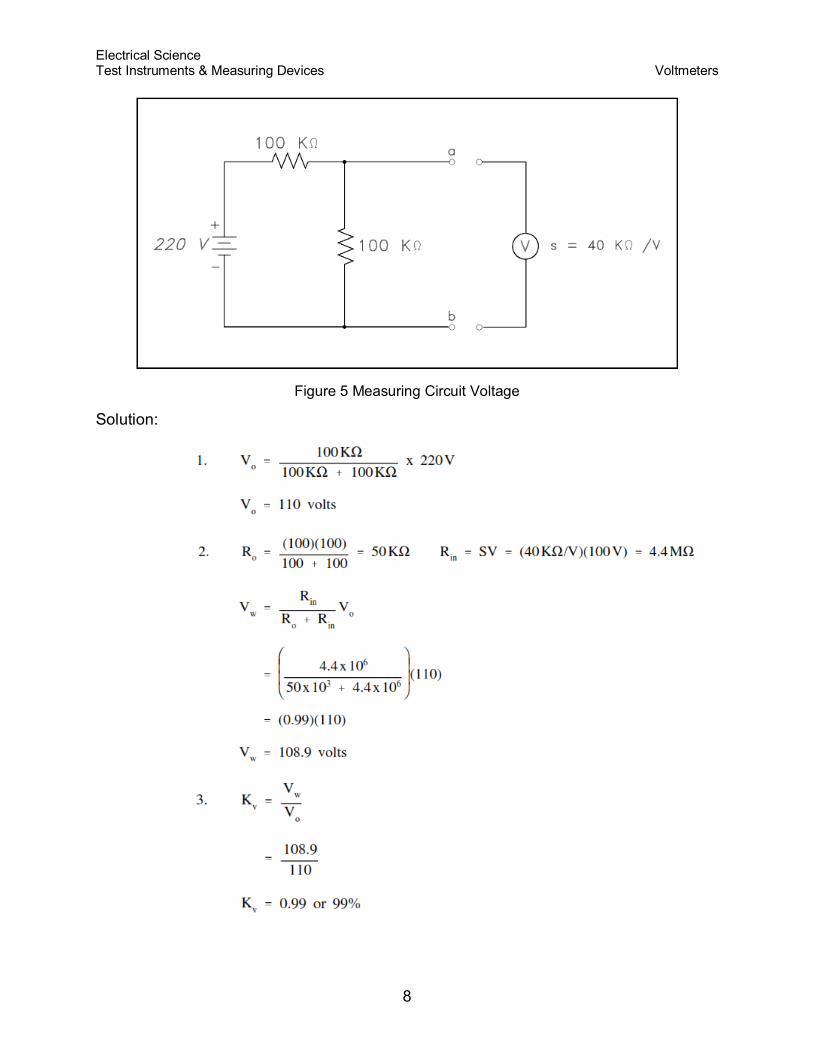
Example: A voltmeter in the 100 volt range with a sensitivity of 40 KΩ/V is to
measure the voltage across terminals a-b (Figure 5).
Find:
1. Vo
2. Vw
3. Kv
Electrical Science Test Instruments & Measuring Devices Voltmeters
8
Figure 5 Measuring Circuit Voltage
Solution:

Electrical Science Test Instruments & Measuring Devices Voltmeters
9
Summary
Voltmeters are summarized below.
Voltmeter Summary
Measures voltage
Connected in parallel with the load being measured

Electrical Science Test Instruments & Measuring Devices Ammeters
10
AMMETERS
Measurement of current being supplied to or from a component is
measured by an ammeter.
EO 1.2 STATE the electrical parameters measured by each of the following
in-place measuring devices:
b. Ammeter
EO 1.3 EXPLAIN how the following electrical test equipment and
measuring devices are connected to a circuit:
b. Ammeter
Ammeter
The ammeter measures electric current. It may be calibrated in amperes, milliamperes,
or microamperes. In order to measure current, the ammeter must be placed in series
with the circuit to be tested (Figure 6).
Figure 6 Ammeter
When an ammeter is placed in series with a circuit, it will increase the resistance of that
circuit by an amount equal to the internal resistance of the meter Rm. Equation (14-3) is
the mathematical representation of the current without the meter installed.
(14-3)
Equation (14-4) is the mathematical representation of the current with the meter
installed in the circuit.
(14-4)

Electrical Science Test Instruments & Measuring Devices Ammeters
11
The accuracy of the ammeter KA is the ratio of the current when the meter is in the
circuit, Iw, to the current with the meter out of the circuit, Io. Equation (14-5) is the
mathematical representation for solving for the accuracy of the ammeter (KA).
(14-5)
By substitution laws, Equation (14-6) is a mathematical representation of the accuracy
using circuit resistance.
(14-6)
The percent loading error is that percent of error due to loading effects that result from
the added resistance of the meter. Equation (14-7) is a mathematical representation of
the percent loading error.
% loading error = (1-KA) (100%) (14-7)
A second error which occurs in an ammeter is calibration error. Calibration error is an
error that occurs due to inaccurately marked meter faces. Typical values of calibration
error in terms of full scale current are about 3 percent.
Figure 7 Ammeter Accuracy
Example: An ammeter, with a 10 mA full scale deflection and an internal resistance
of 400 Ω, is placed in a circuit with a 20 V power source and a 2 KΩ resistor (Figure 7).
Find:
1. accuracy
2. %loading error
3. true current
4. measured current

Electrical Science Test Instruments & Measuring Devices Ammeters
12
1.
2. % loading error = (1 - KA) (100%)
= (1 - 0.833) (100%) = 16.7%
3.
4.
An ammeter with a full scale Im can be shunted with a resistor RSH in order to measure
currents in excess of Im (Figure 8). The reason for shunting an ammeter is to extend the
range of the ammeter and, thereby, measure currents higher than the original full scale
value.

Electrical Science Test Instruments & Measuring Devices Ammeters
13
Figure 8 Ammeter with Shunt
By Kirchhoff s current law,
ISH = IT - Im
Since the voltage across the shunt must
be equal to the voltage across the
ammeter, shunt resistance is calculated
as follows:
Therefore, the input resistance of a shunted ammeter is related to the meter and shunt
resistance. Equation (14-8) is a mathematical representation of this relationship.
NOTE: When computing accuracy for a shunted ammeter, use in place of Rm.
(14-8)
Equation (14-9) is a mathematical representation of the relationship between input
voltage and current to the ammeter and the value of input resistance.
(14-9)
Example: An ammeter, with a 100Ω meter resistance and a full scale deflection
current of 4 mA, is to be shunted to measure currents from 1 to 20 mA.
Find:
1. RSH
2. R1m
Solution:

Electrical Science Test Instruments & Measuring Devices Ammeters
14
Summary
Ammeters are summarized below.
Ammeter Summary
Measure circuit current flow
Connected in series with the circuit
Electrical Science Test Instruments & Measuring Devices Ohm Meters
15
Figure 9 Simple Ohm Meter Circuit
OHM METERS
The resistance of a wire or a circuit is measured by an ohm meter. An
ohm meter aids the troubleshooter in determining if a ground or a short
exists in a circuit.
EO 1.2 STATE the electrical parameters measured by each of the following
in-place measuring devices:
c. Ohm meter
EO 1.3 EXPLAIN how the following electrical test equipment and
measuring devices are connected to a circuit:
c. Ohm meter
Ohm Meter
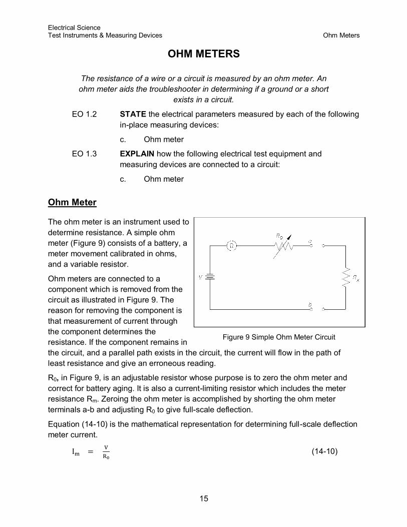
The ohm meter is an instrument used to
determine resistance. A simple ohm
meter (Figure 9) consists of a battery, a
meter movement calibrated in ohms,
and a variable resistor.
Ohm meters are connected to a
component which is removed from the
circuit as illustrated in Figure 9. The
reason for removing the component is
that measurement of current through
the component determines the
resistance. If the component remains in
the circuit, and a parallel path exists in the circuit, the current will flow in the path of
least resistance and give an erroneous reading.
R0, in Figure 9, is an adjustable resistor whose purpose is to zero the ohm meter and
correct for battery aging. It is also a current-limiting resistor which includes the meter
resistance Rm. Zeroing the ohm meter is accomplished by shorting the ohm meter
terminals a-b and adjusting R0 to give full-scale deflection.
Equation (14-10) is the mathematical representation for determining full-scale deflection
meter current.
(14-10)

Electrical Science Test Instruments & Measuring Devices Ohm Meters
16
When the unknown resistance Rx is connected across the ohm meter terminals, the
current is measured by calculating the total series resistance and applying Equation
(14-10). Equation (14-11) is the mathematical representation of this concept.
(14-11)
An easy way to determine ohm meter deflection is by use of a deflection factor (D).
Deflection factor is the ratio of circuit current to meter current. Equation (14-12) is the
mathematical representation of the deflection factor.
(14-12)
The current through the circuit can be determined by solving for I. Equation (14-13) is
the mathematical representation of this relationship.
I = D Im (14-13)
To solve for Rx using Equations (14-10) through (14-13), the relationship between
deflection factor and the meter resistance to the unknown resistance can be shown.
Equation (14-14) is the mathematical representation of this relationship.
(14-14)
If half-scale deflection occurs, then Rx = R0, so that the value of R0 is marked at mid-
scale on the ohm meter face.
Example 1: An ohm meter has a meter movement with a 100 µA full-scale deflection.
The open circuit voltage at terminals a-b is 24 V. The ohm meter is zeroed
and then an unknown resistance Rx is measured, which produces quarter-
scale deflection. Find Rx.
Solution:
First find R0.
Then solve for Rx:
Therefore, quarter scale deflection of this ohm meter face would read 720 KΩ.

Electrical Science Test Instruments & Measuring Devices Ohm Meters
17
Example 2: An ohm meter with R0 = 30Ω, and full scale current Im, = 300 µA. Find I
with: 1) 0Ω, 2) 5Ω, 3) 10Ω, 4) 15Ω, and 5) 1MΩ resistors across the meter
terminal.
Solution:
First, the deflection factor for each resistor must be found.
1. Rx = 0Ω
2. Rx = 5Ω
3. Rx = 10Ω
4. Rx = 15Ω
5. Rx = 1MΩ
Then find I by using:
I = D Im
1. Rx = 0Ω
I = (1) (300 x 10-6) = 300μa full-scale deflection
2. Rx = 5Ω
I = (0.86) (300 x 10-6) = 258μa full-scale deflection
3. Rx = 10Ω
I = (0.75) (300 x 10-6) = 225μa full-scale deflection
4. Rx = 15Ω
I = (0.67) (300 x 10-6) = 201μa full-scale deflection

Electrical Science Test Instruments & Measuring Devices Ohm Meters
18
5. Rx = 1MΩ
I = (0) (300 x 10-6) = 0μa (zero deflection)
NOTE: As the resistance was increased from 0 to 5Ω, meter current decreased by
42 µA. Similarly, when resistance was increased from 5 to 10Ω, the
current decreased by 33 µA. Thus, an ammeter scale used to measure
resistance is nonlinear (Figure 10). The ohm meter scale is a reversal of
the ammeter and voltmeter scales. In other words, the zero resistance (Rx
= 0) is at the right end of the scale and infinite resistance (Rx = 1MΩ) is at
the left end of the scale.
Figure 10 Ohm Meter Scale
Summary
Ohm meters are summarized below.
Ohm Meter Summary
Measures circuit resistance
Connected to a component removed from the circuit

Electrical Science Test Instruments & Measuring Devices Wattmeters
19
WATTMETERS
Wattmeters are used to determine DC power or real AC power delivered
to the load.
EO 1.2 STATE the electrical parameters measured by each of the following
in-place measuring devices:
d. Wattmeter
EO 1.3 EXPLAIN how the following electrical test equipment and
measuring devices are connected to a circuit:
d. Wattmeter
Wattmeter
The wattmeter is an instrument which
measures DC power or true AC power.
The wattmeter uses fixed coils to indicate
current, while the movable coil indicates
voltage (Figure 11). Coils L11 and L12 are
the fixed coils in series with one another
and serve as an ammeter. The two I
terminals are connected in series with the
load. The movable coil Lv, and its
multiplier resistor Rs, are used as a
voltmeter, with the V terminals connected
in parallel with the load. The meter
deflection is proportional to the VI, which
is power.
Figure 11 Wattmeter Schematic
Wattmeters are rated in terms of their maximum current, voltage, and power. All of
these ratings must be observed to prevent damage to the meter.
Equation (14-15) is the mathematical representation of calculating power in a DC circuit.
P = V I or P = I2 R (14-15)
Equation (14-16) is the mathematical representation for calculating power in an AC
circuit.
P = VRms IRms cosӨ or P = I2 R (14-16)
Electrical Science Test Instruments & Measuring Devices Wattmeters
20
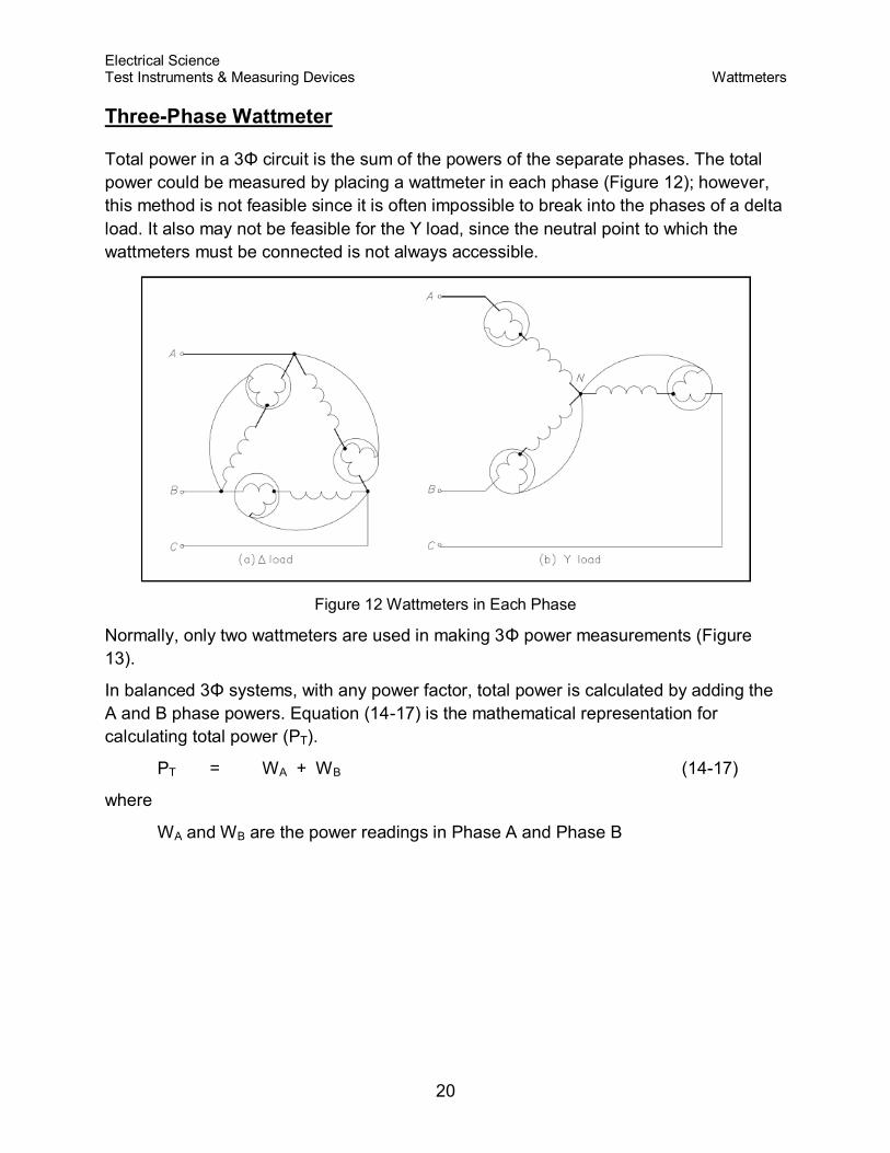
Three-Phase Wattmeter
Total power in a 3Φ circuit is the sum of the powers of the separate phases. The total
power could be measured by placing a wattmeter in each phase (Figure 12); however,
this method is not feasible since it is often impossible to break into the phases of a delta
load. It also may not be feasible for the Y load, since the neutral point to which the
wattmeters must be connected is not always accessible.
Figure 12 Wattmeters in Each Phase
Normally, only two wattmeters are used in making 3Φ power measurements (Figure
13).
In balanced 3Φ systems, with any power factor, total power is calculated by adding the
A and B phase powers. Equation (14-17) is the mathematical representation for
calculating total power (PT).
PT = WA + WB (14-17)
where
WA and WB are the power readings in Phase A and Phase B

Electrical Science Test Instruments & Measuring Devices Wattmeters
21
Figure 13 Two Wattmeters to Measure 3Φ. Power
Summary
Wattmeters are summarized below.
Wattmeter Summary
Measures real power delivered to the load
Single-phase AC or DC - voltage component (movable coil) connected in
parallel with the load and the current component (fixed coil) connected in series
with the load
Three-phase AC - summation of Phase A and B powers
Electrical Science Test Instruments & Measuring Devices Other Electrical Measuring Devices
22
OTHER ELECTRICAL MEASURING DEVICES
Other measuring devices are used to aid operators in determining the
electric plant conditions at a facility, such as the ampere-hour meter,
power factor meter, ground detector, and synchroscope.
EO 1.2 STATE the electrical parameters measured by each of the following
in-place measuring devices:
e. Ampere-hour meter
f. Power factor meter
g. Ground detector
h. Synchroscope
EO 1.3 EXPLAIN how the following electrical test equipment and
measuring devices are connected to a circuit:
e. Ampere-hour meter
f. Power factor meter
g. Ground detector
h. Synchroscope
Ampere-Hour Meter
The ampere-hour meter registers ampere-hours and is an integrating meter similar to
the watt-hour meter used to measure electricity usage in a home. Typical ampere-hour
meters are digital indicators similar to the odometer used in automobiles. The ampere-
hour meter is a direct current meter that will register in either direction depending on the
direction of current flow. For example, starting from a given reading, it will register the
amount of discharge of a battery; when the battery is placed on charge, it will operate in
the opposite direction, returning once again to its starting point. When this point is
reached, the battery has received a charge equal to the discharge, and the charge is
stopped. It is normally desired to give a battery a 10% overcharge. This is accomplished
by designing the ampere-hour meter to run 10% slow in the charge direction. These
meters are subject to inaccuracies and cannot record the internal losses of a battery.
They attempt to follow the charge and discharge, but inherently do not indicate the
correct state of charge. Similar to an ammeter, the ampere-hour meter is connected in
series. Although the ampere-hour meters were used quite extensively in the past, they
have been largely superseded by the voltage-time method of control.

Electrical Science Test Instruments & Measuring Devices Other Electrical Measuring Devices
23
Power Factor Meter
A power factor meter is a type of electrodynamometer movement when it is made with
two movable coils set at right angles to each other. The method of connection of this
type of power factor meter, in a 3Φ circuit, is shown in Figure 14. The two stationary
coils, S and S1, are connected in series in Phase B. Coils M and M1 are mounted on a
common shaft, which is free to move without restraint or control springs. These coils are
connected with their series resistors from Phase B to Phase A and from Phase B to
Phase C. At a power factor of unity, one potential coil current leads and one lags the
current in Phase B by 30o; thus, the coils are balanced in the position shown in Figure
14. A change in power factor will cause the current of one potential coil to become more
in phase and the other potential coil to be more out of phase with the current in Phase
B, so that the moving element and pointer take a new position of balance to show the
new power factor.
Figure 14 3Φ Power Factor Meter Schematic
Ground Detector
The ground detector is an instrument which is used to detect conductor insulation
resistance to ground. An ohm meter, or a series of lights, can be used to detect the
insulation strength of an ungrounded distribution system. Most power distribution
systems in use today are of the grounded variety; however, some ungrounded systems
still exist.

Electrical Science Test Instruments & Measuring Devices Other Electrical Measuring Devices
24
In the ohm meter method (Figure 15), a DC voltage is applied to the conductor. If a
leakage path exists between the conductor insulator and ground, a current will flow
through the ground to the ohm meter proportional to the insulation resistance of the
conductor.
Figure 15 Simple Ohm Meter Ground Detector
In the ground detector lamp method (Figure 16), a set of three lamps connected through
transformers to the system is used. To check for grounds, the switch is closed and the
brilliance of the lamps is observed. If the lamps are equally bright, no ground exists and
all the lamps receive the same voltage. If any one lamp is dark, and the other two lamps
are brighter, the phase in which the darkened lamp is in is grounded. In this case, the
primary winding of the transformer is shorted to ground and receives no voltage.
Figure 16 Ground Detector Lamp Circuit

Electrical Science Test Instruments & Measuring Devices Other Electrical Measuring Devices
25
Synchroscope
A synchroscope indicates when two AC generators are in the correct phase relation for
connecting in parallel and shows whether the incoming generator is running faster or
slower than the on-line generator. The synchroscope consists of a two-phase stator.
The two stator windings are at right angles to one another, and by means of a phase-
splitting network, the current in one phase leads the current of the other phase by 90°,
thereby generating a rotating magnetic field. The stator windings are connected to the
incoming generator, and a polarizing coil is connected to the running generator.
The rotating element is unrestrained and is free to rotate through 360°. It consists of two
iron vanes mounted in opposite directions on a shaft, one at the top and one at the
bottom, and magnetized by the polarizing coil.
If the frequencies of the incoming and running generators are different, the
synchroscope will rotate at a speed corresponding to the difference. It is designed so
that if incoming frequency is higher than running frequency, it will rotate in the clockwise
direction; if incoming frequency is less than running frequency, it will rotate in the
counterclockwise direction. When the synchroscope indicates 0° phase difference, the
pointer is at the "12 o'clock" position and the two AC generators are in phase.
Summary
The important information contained in this chapter is summarized below.
Measuring Devices Summary
Ampere-hour Meter
Measures current flow (either direction) through a given point
Connected in series
Power Factor Meter
Measures power factor between phases in a 3-phase circuit
Connected in series with one phase
Ground Detector
Measures conductor insulation
Connected out of circuit to ground
Synchroscope
Measures relationship between generator frequencies
Connected by a two-phase stator at right angles

Electrical Science Test Instruments & Measuring Devices Test Equipment
26
TEST EQUIPMENT
The multimeter can be used as an ammeter, an ohm meter, or a
voltmeter. Meggers are used to measure insulation resistance.
EO 1.3 EXPLAIN how the following electrical test equipment and
measuring devices are connected to a circuit:
i. Megger
EO 1.4 STATE the electrical parameters measured by each of the following
test instruments:
a. Multimeter
b. Megger
Multimeter
The multimeter is a portable single instrument capable of measuring various electrical
values including voltage, resistance, and current. The volt-ohm-milliammeter (VOM) is
the most commonly used multimeter. The typical VOM has a meter movement with a full
scale current of 50 µA, or a sensitivity of 20 KΩ/V, when used as a DC voltmeter. A
single meter movement is used to measure current, AC and DC voltage, and resistance.
Range switches are usually provided for scale selection (e.g., 0-1V, 0-10V, etc).
Megger
The megger is a portable instrument used to measure insulation resistance. The
megger consists of a hand-driven DC generator and a direct reading ohm meter. A
simplified circuit diagram of the instrument is shown in Figure 17.
The moving element of the ohm meter consists of two coils, A and B, which are rigidly
mounted to a pivoted central shaft and are free to rotate over a C-shaped core (C on
Figure 17). These coils are connected by means of flexible leads. The moving element
may point in any meter position when the generator is not in operation.
As current provided by the hand-driven generator flows through Coil B, the coil will tend
to set itself at right angles to the field of the permanent magnet. With the test terminals
open, giving an infinite resistance, no current flows in Coil A. Thereby, Coil B will govern
the motion of the rotating element, causing it to move to the extreme counter-clockwise
position, which is marked as infinite resistance.

Electrical Science Test Instruments & Measuring Devices Test Equipment
27
Figure 17 Simple Megger Circuit Diagram
Coil A is wound in a manner to produce a clockwise torque on the moving element. With
the terminals marked "line" and "earth" shorted, giving a zero resistance, the current
flow through the Coil A is sufficient to produce enough torque to overcome the torque of
Coil B. The pointer then moves to the extreme clockwise position, which is marked as
zero resistance. Resistance (R1) will protect Coil A from excessive current flow in this
condition.
When an unknown resistance is connected across the test terminals, line and earth, the
opposing torques of Coils A and B balance each other so that the instrument pointer
comes to rest at some point on the scale. The scale is calibrated such that the pointer
directly indicates the value of resistance being measured.
Summary
Test equipment is summarized below.
Test Equipment Summary
Multimeters measure current, voltage, and resistance.
Meggers measure insulation resistance.
Meggers are connected out of circuit.


![Determination of Uncertainty in Measuring Instruments in ......Determination of Uncertainty in Measuring Instruments in Electrical Engineering Programs [172] TecnoLógicas, ISSN-p](https://static.fdocuments.in/doc/165x107/60e125e634d9fa3f7c748302/determination-of-uncertainty-in-measuring-instruments-in-determination-of.jpg)


