EPA Water Treatment Manual - Primary Secondary and Tertiary Treatment
CHAPTER 24
SECONDARY TREATMENT BY
ATTACHED GROWTH AND HYBRID
BIOLOGICAL PROCESS

PRESENTATION OVERVIEW
• Trickling Filters
• Rotating Biological Contactor (RBC)
• Integrated Fixed-film Activated Sludge
(IFAS)
• Moving Bed Biofilm Reactor (MBBR)

Trickling Filters
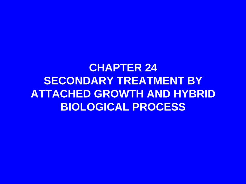
Overview showing primary settling tanks and trickling filters.
Primary
settling tanks
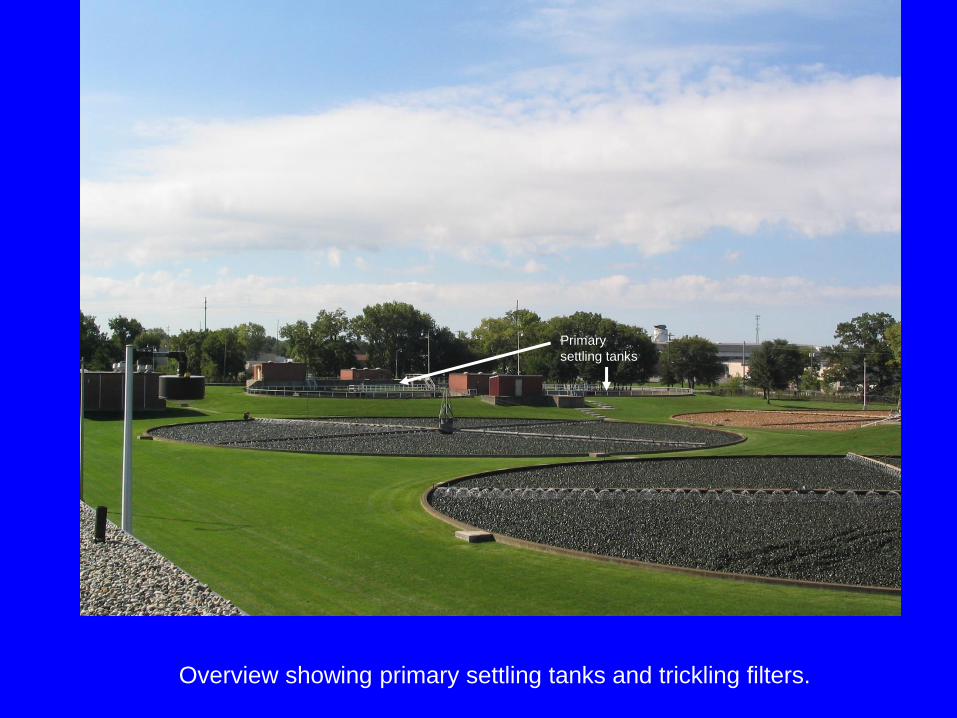
Trickling filter media in a decommissioned filter. Red/orange color is
from precipitated iron that is naturally occurring in raw water.

Slime growth on rocks in an active trickling filter. Note that the media
“pore spaces” are too large to filter.
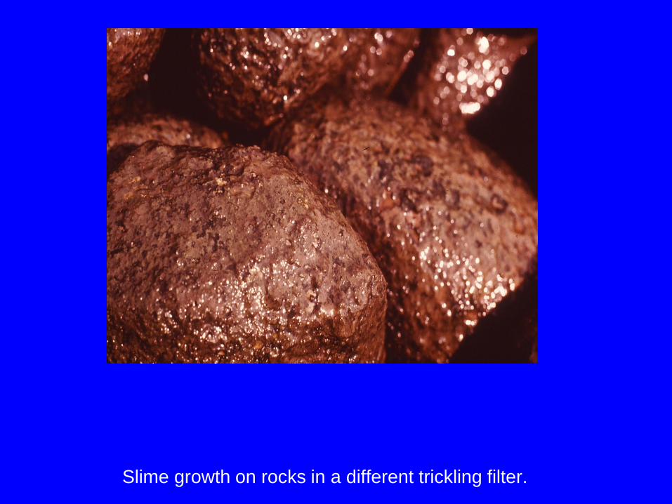
Slime growth on rocks in a different trickling filter.
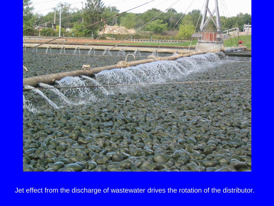
Jet effect from the discharge of wastewater drives the rotation of the distributor.

Rotation of the distributor is shown in the next series of slides.
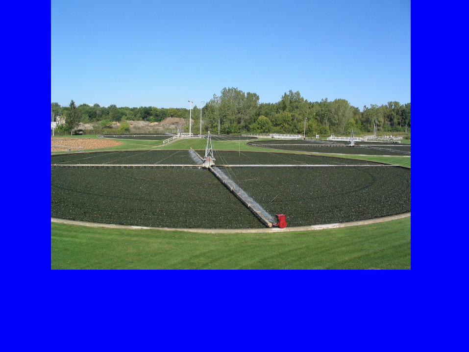


The “brown” tricking filter has been taken out of service prior to
decommissioning. The slime growth has died. The filter was washed
with treated “clear” water to wash the organic matter from the media.
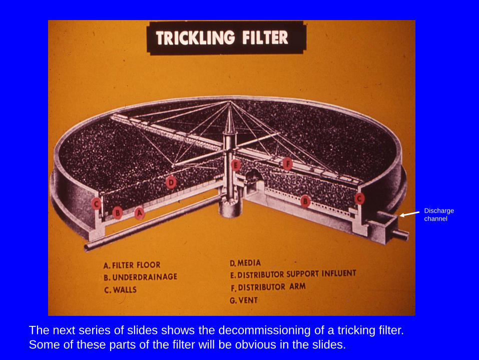
The next series of slides shows the decommissioning of a tricking filter.
Some of these parts of the filter will be obvious in the slides.
Discharge
channel
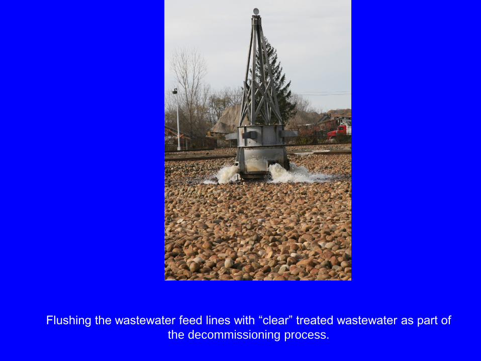
Flushing the wastewater feed lines with “clear” treated wastewater as part of
the decommissioning process.

Excavation of the media from the trickling filter. The white lines show
the pattern of the filter drain blocks.

The white lines are snow. The dark lines are small ridges of soil
material that settled between the filter drain blocks.

Broken filter drain blocks.
Filter drain
blocks

Discharge channel from the trickling filter.
Discharge
channel
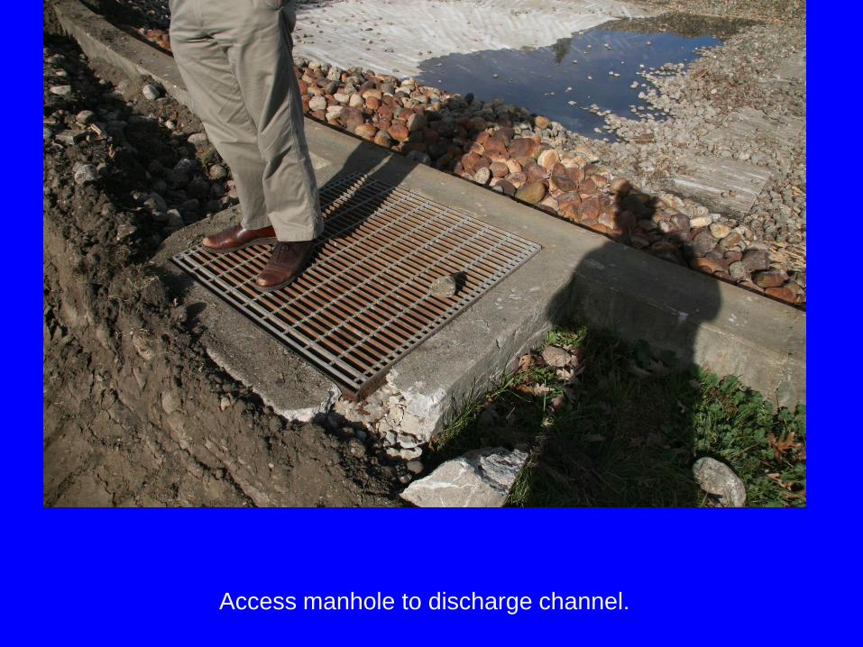
Access manhole to discharge channel.

Rotating Biological Contactor (RBC)
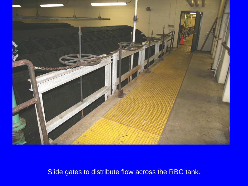
Slide gates to distribute flow across the RBC tank.

Two parallel flow RBC tanks enclosed in single room. This arrangement allows
operators to visually compare the behavior of the individual RBCs. If one “wobbles”
it is immediately obvious in comparison to the others. This wobble is evidence of
asymmetrical loading that potentially leads to catastrophic mechanical failure.

A single RBC.

The wastewater in the tank is aerated. These RBCs are rotated by “air power.”
The rising air pushes against the louvers to impart the rotation motion. This
system works well provided that the RBC does not become overloaded with
biological growth.
Louvers

Another view of the “turning” louvers on the RBC.

Biological slime growth on the RBC.

Heavy biological slime growth on the RBC.
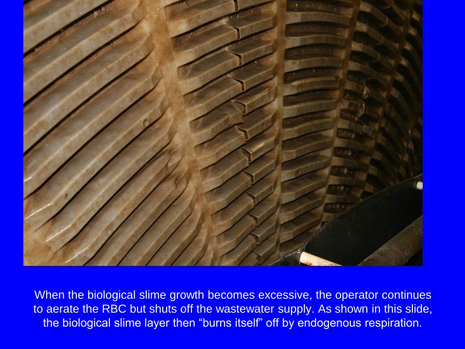
When the biological slime growth becomes excessive, the operator continues
to aerate the RBC but shuts off the wastewater supply. As shown in this slide,
the biological slime layer then “burns itself” off by endogenous respiration.

The axel of the RBC is mounted on the walkway between the tanks.
Note the plastic sheeting to keep spray off the walkway.

A load cell is placed beneath the axel to keep track of the load on the RBC. As
the slime layer grows the load cell transmits the weight to a central computer.
This is another measure to keep from overloading the RBC.
Load cell
Integrated Fixed-film Activated Sludge
(IFAS)

IFAS BioWeb™ media.
Courtesy of Entex Technologies

Installation of a BioWeb™ IFAS. Note fine bubble aerators below the IFAS unit.
Courtesy of Entex Technologies

Moving Bed Biofilm Reactor (MBBR)
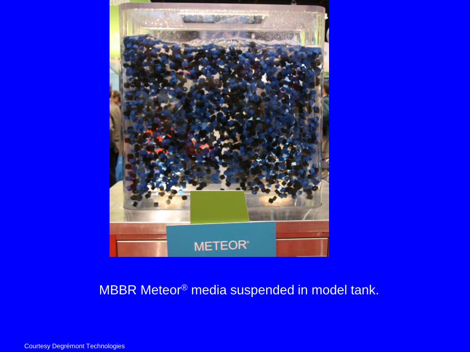
MBBR Meteor® media suspended in model tank.
Courtesy Degrémont Technologies

Close up view of MBBR media.
Courtesy Degrémont Technologies

Trickling Filter (1)
• Berbentuk unggun diam (fixed bed)
dengan kedalaman sekitar 1-3 meter
• Menggunakan batu sebagai media tempat
bertumbuhnya mikroba
• Air limbah dipercikan dari atas melalui
suatu lengan yang dapat berputar

Trickling Filter (2)

Trickling Filter (3)
• Diagram penampang trickling filter :
Trickling Filter (4)
• Kebutuhan udara pada trickling filter dapat
disuplai dengan dua cara :
– Natural draft : mengandalkan perpindahan
alami karena adanya perbedaan suhu pada
tiap bagian unggun
– Forced draft : menggunakan blower

Perancangan Trickling Filter (1)
• Perancangan dengan menggunakan
perhitungan eksak sulit dilakukan karena
harus memperhitungkan sejumlah faktor
• Perancangan lebih sering menggunakan
persamaan-persamaan empirik

Perancangan Trickling Filter (2)
• Efisiensi pengolahan dengan trickling filter
dihitung dengan persamaan :
• F adalah recirculation factor yang dapat
dihitung dengan rumus :
5,01
12,41
1
+
=
FV
CQE
in
( )21,01
1
R
RF
+
+=
Perancangan Trickling Filter (3)
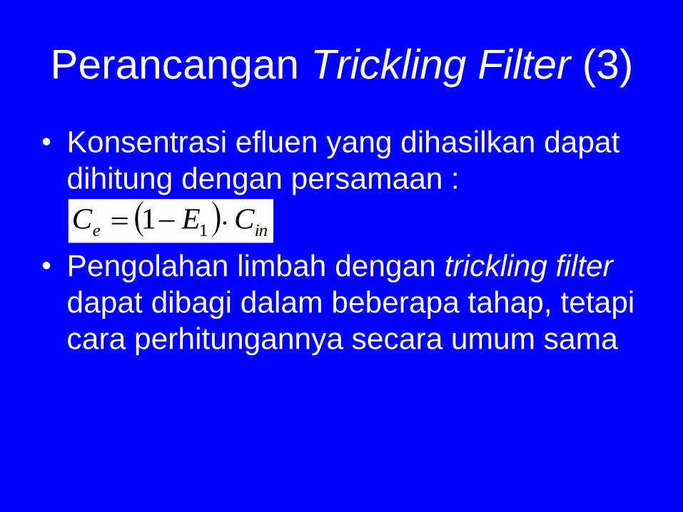
• Konsentrasi efluen yang dihasilkan dapat
dihitung dengan persamaan :
• Pengolahan limbah dengan trickling filter
dapat dibagi dalam beberapa tahap, tetapi
cara perhitungannya secara umum sama
( ) ine CEC −= 11
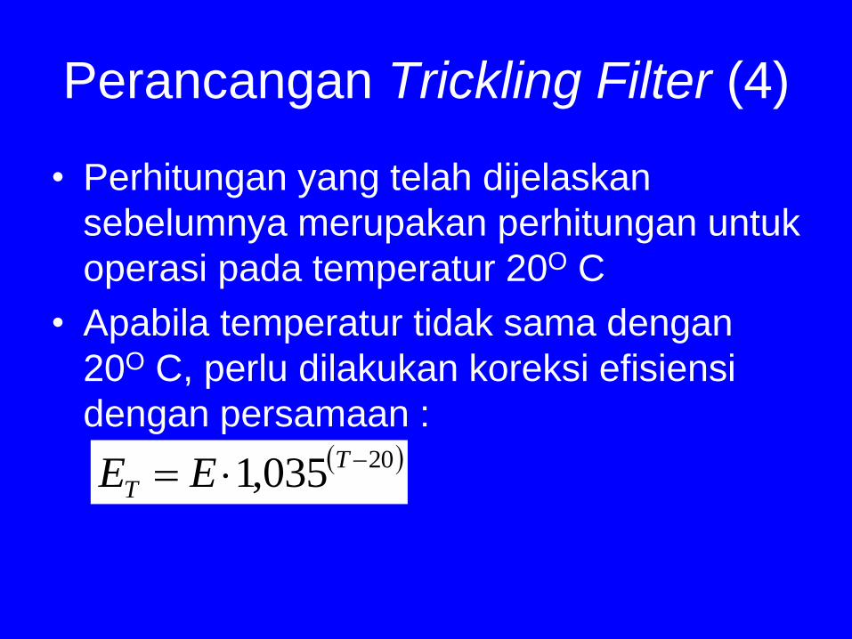
Perancangan Trickling Filter (4)
• Perhitungan yang telah dijelaskan
sebelumnya merupakan perhitungan untuk
operasi pada temperatur 20O C
• Apabila temperatur tidak sama dengan
20O C, perlu dilakukan koreksi efisiensi
dengan persamaan :( )20035,1 −= T
T EE

Rotating Bio Contactors (1)
• Mikroba tumbuh pada suatu pelat
lingkaran yang berputar
• Sebagian pelat terendam dalam air limbah
yang akan diolah
• Pada saat pelat berputar, terjadi
pergantian periodik antara kontak
mikroba-air limbah dan mikroba-udara

Rotating Bio Contactors (2)
• Diagram alat :