Chapter 21: Synthetic Aperture Radar - Helitavia
23
CHAPTER 21 SYNTHETIC APERTURE RADAR L J. Cutrona Sarcutron, Inc. 21.1 BASIC PRINCIPLES AND EARL Y HISTORY For airborne ground-mapping radar there has been continuous pressure and de- sire to achieve finer resolution. Initially, this finer resolution was achieved by the application of "brute-force" techniques. Conventional radar systems of this type were designed to achieve range resolution by the radiation of a short pulse and azimuth resolution by the radiation of a narrow beam. The range resolution problem and some of the pulse compression techniques are discussed in Chap. 10. There it is shown that techniques are available for achieving a resolution significantly finer than that corresponding to the pulse width, provided a signal of sufficient bandwidth is transmitted. Since pulse com- pression is adequately treated in that chapter, the present chapter will discuss pulse compression techniques only for cases in which the pulse compression technique is intimately involved with synthetic aperture techniques. This is par- ticularly true for configurations that perform both pulse compression and azimuth compression simultaneously rather than with techniques that perform range com- pression and azimuth compression sequentially. The basic technology discussed in this chapter is the exploitation of synthetic aperture techniques for improving the azimuth resolution of a mapping radar to a value significantly finer than that achievable by making use of the radiated beamwidth. Synthetic aperture radar (SAR) is based on the generation of an effective long antenna by signal-processing means rather than by the actual use of a long phys- ical antenna. In fact, only a single, relatively small, physical antenna is used in most cases. In considering a synthetic aperture, one makes reference to the characteristics of a long linear array of physical antennas. In that case, a number of radiating elements are constructed and placed at appropriate points along a straight line. In the use of such a physical linear array, signals are fed simultaneously to each of the elements of the array. Similarly, when the array is used as a receiver, the elements receive signals simultaneously; in both the transmitting and the receiv- ing modes, waveguide or other transmission-line interconnections are used, and interference phenomena are exploited to get an effective radiation pattern. The radiation pattern of a linear array is the product of two quantities if the
Transcript of Chapter 21: Synthetic Aperture Radar - Helitavia
CHAPTER 21SYNTHETIC APERTURE RADAR
L J. CutronaSarcutron, Inc.
21.1 BASIC PRINCIPLES AND EARL Y HISTORY
For airborne ground-mapping radar there has been continuous pressure and de-sire to achieve finer resolution. Initially, this finer resolution was achieved by theapplication of "brute-force" techniques. Conventional radar systems of this typewere designed to achieve range resolution by the radiation of a short pulse andazimuth resolution by the radiation of a narrow beam.
The range resolution problem and some of the pulse compression techniquesare discussed in Chap. 10. There it is shown that techniques are available forachieving a resolution significantly finer than that corresponding to the pulsewidth, provided a signal of sufficient bandwidth is transmitted. Since pulse com-pression is adequately treated in that chapter, the present chapter will discusspulse compression techniques only for cases in which the pulse compressiontechnique is intimately involved with synthetic aperture techniques. This is par-ticularly true for configurations that perform both pulse compression and azimuthcompression simultaneously rather than with techniques that perform range com-pression and azimuth compression sequentially.
The basic technology discussed in this chapter is the exploitation of syntheticaperture techniques for improving the azimuth resolution of a mapping radar to avalue significantly finer than that achievable by making use of the radiatedbeam width.
Synthetic aperture radar (SAR) is based on the generation of an effective longantenna by signal-processing means rather than by the actual use of a long phys-ical antenna. In fact, only a single, relatively small, physical antenna is used inmost cases.
In considering a synthetic aperture, one makes reference to the characteristicsof a long linear array of physical antennas. In that case, a number of radiatingelements are constructed and placed at appropriate points along a straight line. Inthe use of such a physical linear array, signals are fed simultaneously to each ofthe elements of the array. Similarly, when the array is used as a receiver, theelements receive signals simultaneously; in both the transmitting and the receiv-ing modes, waveguide or other transmission-line interconnections are used, andinterference phenomena are exploited to get an effective radiation pattern.
The radiation pattern of a linear array is the product of two quantities if the

radiating elements are identical. The radiation pattern of the array is the radiationpattern of a single element multiplied by an array factor. The array factor hassignificantly sharper lobes (narrower beamwidths) than the radiation patterns ofthe elements of the array. The half-power beamwidth (3, in radians, of the arrayfactor of such an antenna is given by
P = I (21.1)
In this expression, L is the length of the physical array, and X is the wavelength.In the synthetic antenna* case, only a single radiating element is used in most
instances. This antenna is translated to take up sequential positions along a line.At each of these positions a signal is transmitted, and the radar signals received inresponse to that transmission are placed in storage. It is essential that the storagebe such that both amplitude and phase of received signals are preserved.
After the radiating element has traversed a distance Leff, the signals in storageresemble strongly the signals that would have been received by the elements ofan actual linear array. Consequently, if the signals in storage are subjected to thesame operations as those used in forming a physical linear array, one can get theeffect of a long antenna aperture. This idea has resulted in the use of the termsynthetic aperture to designate this technique.
In the case of an airborne ground-mapping radar system, the antenna usuallyis mounted to be side-looking, and the motion of the aircraft carries the radiatingelement to each of the positions of the array. These array positions are the loca-tion of the physical antenna at the times of transmission and reception of the ra-dar signals.
The designer of a synthetic aperture radar has available a number of degreesof freedom that are not available to the designer of a physical linear array. Thesedegrees of freedom derive from the fact that the signals in storage can be selectedby range and that, if desired, a different operation can be performed on the sig-nals at different ranges. One important operation of this type is that of focusing.
A physical linear array can be focused to a specific range. There will then bea depth of focus surrounding this range. However, most physical linear arrays areunfocused. This is sometimes stated by saying that the antenna is "focused atinfinity." In a synthetic aperture radar, however, it is possible to focus eachrange separately by the proper adjustment of the phases of the received signalsbefore the summation; this results in the effective synthetic aperture. Further-more, if desired, a different weighting can be applied to each range, although usu-ally the same type of weighting is used at all ranges.
There is another important difference between physical linear arrays and syn-thetic linear arrays. This difference results in the synthetic aperture having a res-olution finer by a factor of 2 than that corresponding to a real linear array of thesame length. Qualitatively, the following discussion indicates the physics result-ing in this factor of 2. In a more general analysis, the factor 2 arises naturally.
In a physical linear array, the transmission of the signals results in an illu-mination of the target area. The angle selectivity of the linear array is pro-vided only during the reception process. During this process, the differencesin phase received by each element of the linear array give the antenna pattern.In the synthetic antenna radar, on the other hand, a single element radiatesand receives signals. Consequently, the round-trip phase shift is effective informing the effective radiation pattern. This relationship is written as
* The terms synthetic antenna and synthetic aperture are used interchangeably in this chapter.

Peff = 5T- (2L2)^Leff
Here peff is the effective half-power beamwidth of the synthetic aperture, and Leffis the length of the synthetic aperture.
A more detailed derivation of the resolution capability of a synthetic apertureradar will be given later in this chapter. The following derivation is that initiallymade by the author and his colleagues in the early days of synthetic aperture ra-dar.
Let D represent the horizontal aperture of the physical antenna carried by anairborne ground-mapping radar. The width of the horizontal beam at range Rgives the maximum value for the length of synthetic aperture that can be used atthat range. Since the beamwidth of such an antenna is given by the ratio of thewavelength X to its horizontal aperture D, the maximum length of this syntheticantenna aperture is given by
La = f (21.3)
The linear resolution in azimuth 8a is the product of the effective beamwidthgiven by Eq. (21.2) and the range R:
8a = Peff* (21.4)
If Eqs. (21.2) and (21.3) are combined with Eq. (21.4), one obtains
» _ *• o _ M D - D ot ^8«~ 2Z^*-T J^ "I (2L5)
It will be noted that Eq. (21.5) indicates an azimuth linear resolution independentof both range and wavelength. Moreover, the result indicates that finer resolutionis achievable with smaller rather than larger physical apertures. This spectacularresult formed much of the motivation of the research in synthetic antenna radar.
The author was first exposed to the idea of a synthetic antenna radar in 1953,during a summer study which launched a program known as Project Michigan.During that summer, the ideas relating to synthetic antennas were presented byDr. C. W. Sherwin,1 then of the University of Illinois, Dr. Walt Hausz of theGeneral Electric Company, and J. Koehler, at that time with Philco Corporation.Subsequently, it came to the author's attention that Carl Wiley and the GoodyearAircraft Company had already undertaken some work and had made substantialprogress in the synthetic-antenna area.
The Pioneer Award of the IEEE Aerospace and Electronic Systems Societywas given to Carl Wiley in 1985 for his work in synthetic aperture radar. His re-marks from that presentation are given in Ref. 2 and relate some of the early his-tory of SAR.
Most of the early workers considered an unfocused synthetic antenna. How-ever, Dr. Sherwin indicated that finer resolution should be achievable by usingfocusing because this technique removed what would otherwise be a restrictionon the maximum length of synthetic antenna that could be used. The author and

his colleagues at the University of Michigan undertook development of the fo-cusing concept suggested by Dr. Sherwin.
27.2 FACTORS AFFECTING RESOLUTION OF ARADAR SYSTEM
In the following paragraphs a brief comparison of the conventional antenna, theunfocused synthetic antenna, and the focused antenna is given.3'4 The languageof synthetic apertures is used, and a comparison of the resolution capability forthree cases is given. A more sophisticated derivation of simultaneous resolutionin range and azimuth will be given later in this chapter.
Three cases are compared for their azimuth resolution capability: (1) the con-ventional technique, in which azimuth resolution depends upon the width of theradiated beam; (2) the unfocused synthetic antenna technique, in which the syn-thetic antenna length is made as long as the unfocused technique permits; and (3)the focused synthetic antenna technique, in which the synthetic antenna length ismade equal to the linear width of the radiated beam at each range.
The linear azimuth resolution for the conventional case is given by
\ DResolutionconv = — (21.6)
For the unfocused case, the resolution is
Resolutionunf = 1X2Vx/? (21.7)
whereas for the focused case, the resolution is
Resolutionfoc = — (21.8)
where X = wavelength of radar signal transmittedD = horizontal aperture of antennaR = radar range
Figure 21.1 is a plot of the resolution for each of these cases as a function ofradar range. This plot is for an antenna aperture of 5 ft and a wavelength of 0.1 ft.
Conventional Technique. The conventional technique for achieving azimuthresolution has been that of radiating a narrow beam. In this case the resolutionof a target depends upon whether the target is included within the half-powerpoints of the radiated beam, although some techniques exist for resolvingtargets somewhat less than a beamwidth apart.
The computation of the linear azimuth resolution for the conventional case iswell known. The appropriate expression is obtained by noting that the width ofthe radiated beam, in radians, is given by the ratio XlD whereas the linear widthof the beam at range R is the product of this beamwidth and range. These con-siderations lead to the result already written as Eq. (21.6).
A consideration from antenna theory is that Eq. (21.6) applies only to the far-

RANGE (nmi)BIG. 21.1 Azimuth resolution for three cases:curve a, conventional; curve b, unfocused;curve c, focused.
field pattern of an antenna. The beginning of the far field occurs at a distance*min for which
*min ~ Y (2L9)
It will be noted by substitution of Eq. (21.9) that the finest resolution achiev-able by the conventional technique is given by
Minimum conventional resolution = D (21.10)
The Unfocused Synthetic Aperture. The simpler of the synthetic antennatechniques is that which generates an unfocused synthetic aperture. In thiscase, the coherent signals received at the synthetic array points are integrated,with no attempt made to shift the phasesof the signals before integration. Thislack of phase adjustment imposes a max-imum upon the synthetic antenna lengththat can be generated. This maximumsynthetic antenna length occurs at agiven range when the round-trip distancefrom a radar target to the center of thesynthetic array differs by X/4 from theround-trip distance between the radartarget and the extremities of thesynthetic aperture array.
The pertinent geometry is shown inFig. 21.2. In this figure, R0 represents therange from a radar target to the center of the array, and Leff represents the max-imum synthetic antenna length such that the distance from the target to the ex-tremities of the synthetic aperture does not exceed R0 + X/8.
It is evident from this geometry that
(*+!)2-¥+*2 (2U1)
FIG. 21.2 Geometry for an unfocusedsynthetic antenna.
CURVE c (FOCUSED CASE)
CURVE a(CONVENTIONAL CASE)
CURVEb(UNFOCUSED CASE)
RESO
LUTI
ON (ft
)

If this expression is solved for Leff, subject to the assumption that X/16 is smallcompared with R09 the result is
Leff = VR^ (21.12)
Combination of Eqs. (21.2) and (21.12) gives
Peff = ijJ|- rad (21.13)2 \]KQ
Multiplying this beam width by range results in the resolution given by Eq. (21.7).It will be noted that for the unfocused case the transverse linear resolution is
independent of the antenna aperture size, fineness of resolution is increased bythe use of shorter wavelengths, resolution varies as the square root of X, and theresolution deteriorates as the square root of range. A plot of Eq. (21.7) is given inFig. 21.1.
The Focused Case. An expression for the resolution achievable in thefocused case has been given as Eq. (21.8). It is significant that the azimuthresolution achievable for this case depends only upon the physical antennaaperture and that, in contradistinction to the conventional case, fine resolutionrequires the use of small rather than large antennas. Also significant is the factthat the achievable resolution for a given antenna size is independent both ofthe range and of the wavelength used. A graph of Eq. (21.8) is also shown inFig. 21.1.
In order to achieve the resolution indicated by Eq. (21.8), the synthetic ap-erture length required is
Lef[=™ (21-14)
The considerations used in arriving at Eq. (21.12) indicated that, unless additionalprocessing were applied to the signals, antenna lengths such as those implied byEq. (21.14) could not be achieved. The processing required is an adjustment ofthe phases of the signals received at each point of the synthetic antenna, whichmakes these signals of equal phase (cophase) for a given target. If this is done,the restrictions which limited the maximum antenna length to that given by Eq.(21.12) are no longer pertinent and the new limitation on the length of the syn-thetic antenna achievable becomes simply the linear width of the radiated beamat the range of the target.
In some cases, a resolution coarser than DII is sufficient. Then a fraction y ofthe maximum focused synthetic antenna length can be used. For this case
^eff = ̂ (21-15)
and the achievable resolution is
Resolutionfoc = — (21.16)

For situations in which the synthetic antenna length given by Eq. (21.15) isless than or equal to the synthetic antenna length for the unfocused case as givenby Eq. (21.12), only a limited improvement in resolution is achievable for the fo-cused case. However, if a resolution finer than that given by Eq. (21.7) is desired,focusing must be used. Focusing removes the restriction on synthetic aperturelength that would otherwise apply.
21.3 RADARSYSTEMPRELIMINARIES
Whether or not synthetic aperture generation is used, a number of componentsare required for a radar system. The use of a synthetic antenna and/or pulse com-pression places additional requirements on some of these components, especiallywith respect to coherence and stability.
It is the purpose of this section to present a block diagram of the portions ofthe radar system that precede the signal processor. A block diagram and severalvariants are described. The major variant is for the purpose of describing thetransmitter-receiver portions of a radar system for the cases of synthetic antennageneration alone as compared with the case of synthetic antenna generation com-bined with pulse compression. The signal-processing operations will be discussedlater.
The essential elements of a radar system useful in a synthetic aperture situa-tion are shown in Fig. 21.3. The components that determine the radiatedwaveform are shown within the dotted lines in the upper left-hand corner of thediagram. This equipment consists of two stable oscillators. One of them is a local
FIG. 21.3 Block diagram of a coherent radar system.
LCXFREQUENCY-
DEVIABLEOSCILLATOR
MIXER 1 POWERAMPLIFIER DUPLEXER
ANTENNA
WAVEFORM GENERATOR
IFOSCILLATOR
O)2
* DETECTOR IFAMPLIFIER MIXER 2 RF
AMPLIFIER
BIPOLAR VIDEO
VIDEOAMPLIFIER RECORDER IF OPTICAL PROCESSING IS USED
IF ELECTRONIC PROCESSING IS USEDTO PROCESSOR

oscillator (LO) at radian frequency o>2. The outputs of these oscillators are fedinto mixer 1. In this mixer, a multiplicity of sum and difference frequencies isgenerated, and either the sum frequencies or the difference frequencies are se-lected and fed to the power amplifier.
If synthetic antenna generation without pulse compression is to be accom-plished, the dotted component labeled "frequency-deviable oscillator" is notused, and the local oscillator is fed directly into mixer 1.
If pulse compression is to be combined with synthetic antenna generation, afrequency-deviable oscillator (FDO) is used for obtaining the desired waveform.In this case, the local oscillator is used to lock in the FDO. A ramp voltage isused to linearly frequency-modulate the FDO. This linearly frequency-modulatedsignal is then fed into mixer 1, instead of the LO signal, for the case of pulsecompression. Waveforms other than linear frequency modulation may be usedfor pulse compression. In Fig. 21.3 the output of the video amplifier is fed to arecorder if optical processing is to be performed and/or to an electronic proces-sor.
27.4 SIGNAL-PROCESSING THEORY
The theory of synthetic antenna generation combined with pulse compression iscarried out below to show the information theoretic considerations involved andto indicate the operations necessary for achieving both azimuth synthetic antennageneration and pulse compression. A combined range-azimuth resolution func-tion is derived. Following this treatment, an analysis of the signal-to-noise-ratiocharacteristics of a synthetic antenna compression radar are analyzed.
Detailed Resolution Analysis. The analysis will be carried out in terms of anambiguity function whose properties indicate both the azimuth and the rangeresolution of the system. In the analysis, some conditions are stated for whichthe terms affecting range resolution can be factored from the elements affectingazimuth resolution, so that the resulting ambiguity function can be written asthe product of two factors, one for range and one for azimuth.
Role of the Generalized Ambiguity Function. In this subsection, a definitionof a generalized ambiguity function will be given, and its role in determining theresolution of a system will be interpreted.
To determine the generalized ambiguity function for a radar system, let awaveform f(f) be radiated. We consider the operations performed upon the re-ceived signals with the objective of determining the radar reflectivity of the ter-rain being mapped. The function f(f) may assume a variety of forms and may bea succession of short signals. If the quantity p(x,y,z) represents the reflectivity ofthe terrain being mapped, the signal received by a radar system can be describedby
*W = f f ff>(x,y,z)f\t - —} dx dy dz (21.17)JJJ L CJ
The integration extends over the illuminated patch, and R is the range between apoint (x,y,z) on the ground and the radar position (v/,0,/z). This equation showsthat the received signal is the superposition of a large number of reflections
within the illuminated pattern of the antenna and within the range gate which ar-rive simultaneously at the radar antenna.
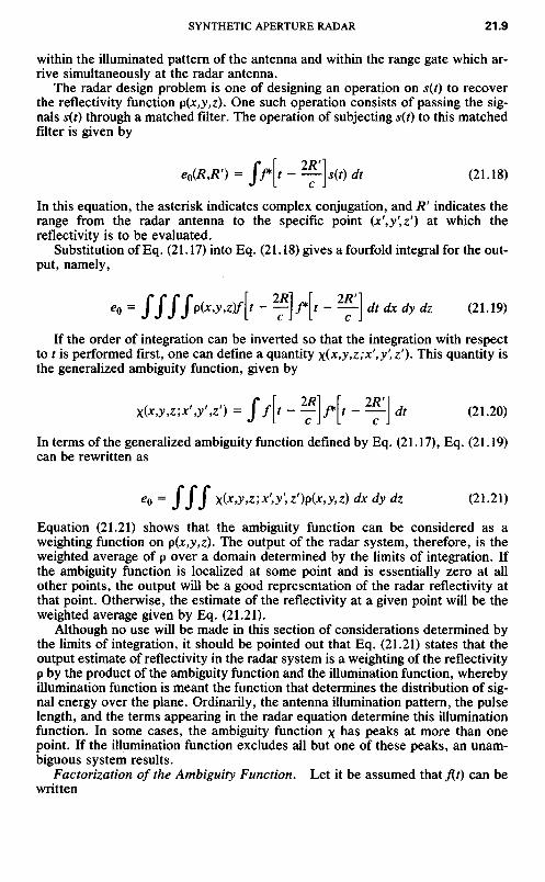
The radar design problem is one of designing an operation on s(t) to recoverthe reflectivity function p(x,y,z). One such operation consists of passing the sig-nals s(t) through a matched filter. The operation of subjecting s(t) to this matchedfilter is given by
/r 2/?'i
Hr--Uf)A (21.18)L c J
In this equation, the asterisk indicates complex conjugation, and R' indicates therange from the radar antenna to the specific point (x',y',z') at which thereflectivity is to be evaluated.
Substitution of Eq. (21.17) into Eq. (21.18) gives a fourfold integral for the out-put, namely,
eQ = J JJJp(*0^)/[' ~ y] f\t - ̂ ] dt dx dy dz (21.19)
If the order of integration can be inverted so that the integration with respectto t is performed first, one can define a quantity x(x,y,z;x',y'tz'). This quantity isthe generalized ambiguity function, given by
/r 9/?i r 9T?'!
f i t \J*\t-—\dt (21.20)L c J L c J
In terms of the generalized ambiguity function defined by Eq. (21.17), Eq. (21.19)can be rewritten as
e0 = JJJ X(xy,z;x',y',z')p(x9y,z) dx dy dz (21.21)
Equation (21.21) shows that the ambiguity function can be considered as aweighting function on p(x,y,z). The output of the radar system, therefore, is theweighted average of p over a domain determined by the limits of integration. Ifthe ambiguity function is localized at some point and is essentially zero at allother points, the output will be a good representation of the radar reflectivity atthat point. Otherwise, the estimate of the reflectivity at a given point will be theweighted average given by Eq. (21.21).
Although no use will be made in this section of considerations determined bythe limits of integration, it should be pointed out that Eq. (21.21) states that theoutput estimate of reflectivity in the radar system is a weighting of the reflectivityp by the product of the ambiguity function and the illumination function, wherebyillumination function is meant the function that determines the distribution of sig-nal energy over the plane. Ordinarily, the antenna illumination pattern, the pulselength, and the terms appearing in the radar equation determine this illuminationfunction. In some cases, the ambiguity function x has peaks at more than onepoint. If the illumination function excludes all but one of these peaks, an unam-biguous system results.
Factorization of the Ambiguity Function. Let it be assumed that f(f) can bewritten

M = g(t)e^ (21.22)
In this equation, g(t) is considered a complex function having both magnitude andphase, whereas O)0 represents a carrier frequency. If f(t) with the form given byEq. (21.22) is used in Eq. (21.20), one obtains for the ambiguity function the ex-pression
X = fg\* - —1 **[> - —I *'WWc - 2R>/C) dt (21.23)J L c J L c J
Let J(t) consist of a sequence of transmissions. It is assumed that successivetransmissions may be alike or that they may be different. Thus fit) will have thecharacteristics of being nonzero for a sequence of time intervals and of being zerootherwise. Further, let it be assumed that the exponential term in Eq. (21.23) var-ies slowly during each of these transmissions. This is equivalent to a statementthat the electrical path length between a target and the radar changes by a smallamount during each transmission. If this assumption is valid, the exponentialterm in Eq. (21.23) can be considered a constant during a given transmission, al-though it will vary between transmissions.
The integral that is the coefficient of the exponential term in Eq. (21.23) hasthe form of an autocorrelation function of g with itself. This autocorrelation func-tion for g is given by Eq. (21.24). It will be noted that the autocorrelation functionof g is a function of the difference in range R-R'. In Eq. (21.24) the integral iscarried out over the times that g(t - 2RIc) overlaps g*(t - 2R'/c) for a giventransmission.
**-/•(-3 4-fl-«4"-T] <-<>
If the notation given by Eq. (21.24) is used, one obtains
X = 24> J— - —I e-**™ ~ 2^ (21.25)**L C C J
Examination of Eq. (21.25) shows that if <|> ,̂ the autocorrelation function for g,is the same function for each member of the sequence of transmissions, then thiselement can be factored out and written outside the summation term of Eq.(21.25). The expression after this common term has been factored out is
X = 4>J^ - ̂ f] Ze-^2*1' ~ *'V (21.26)
The summation term in Eq. (21.26) gives the azimuth resolution of the system,whereas the term $g? gives the range resolution. It is evident from Eq. (21.26)that the autocorrelation function of g rather than g itself determines the rangeresolution of the system.
A variety of waveforms have been used to achieve range resolution. Amongthem the two most important are those in which g(t) is a short pulse and those inwhich g(t) is a linearly frequency-modulated short pulse (chirped signal). It is, of
course, evident that any other waveform having a desirable autocorrelation func-tion is equally possible for g(t).
The form of g(t) to be analyzed is that of the linearly frequency-modulatedcase.
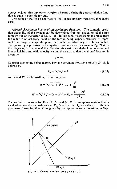
Azimuth Resolution Factor of the Ambiguity Function. The azimuth resolu-tion capability of the system can be determined from an evaluation of the sumterm written as the factor in Eq. (21.26). In this sum, R represents the range fromthe radar to an arbitrary point on the terrain being mapped, whereas R' repre-sents the range to a specific point for which the reflectivity is to be estimated.The geometry appropriate to the synthetic antenna case is shown in Fig. 21.4. Inthis diagram, it is assumed that the aircraft carries a side-looking antenna andflies at height h and with velocity v along the jc axis so that the aircraft location isgiven by
JC = Vt
Consider two points being mapped having coordinates (0,;y(),0) and (jt',y(),0). R() isdefined by
^o = VV + h2 (21.27)
and R and R' can be written, respectively, as
2R = VV + x2 ~ /C0 + JL- (21.28)
2/C0
V '—i (x - x')2
R(2 + (jc- x')2 « R() + .p (21.29)
2/C0
The second expression for Eqs. (21.28) and (21.29) is an approximation that isvalid whenever the inequalities x«R(}, (x - x') « /?() are satisfied. If the ap-proximate forms for R-R' as given by the approximate expressions in Eqs.
FIG. 21.4 Geometry for Eqs. (21.27) and (21.28).
AIRCRAFT

(21.28) and (21.29) are used to evaluate the sum appearing in Eq. (21.26), oneobtains
<£e-i<w(2R/c - 2R1Ic] _ ££-/(2a>o/c)(2xjt' - x'2)/2RQ (21.30)
Thus far, the summation index has not been defined. To proceed further, it isnecessary to indicate the summation index and its bounds. Let it be assumed thatthe transmissions radiated are a sequence of pulses with time intervals betweenpulses that are multiples of T. Then the variable x can be given as an integralmultiple of the distance vT moved between successive transmissions. This rela-tionship is
jc = nvT (21.31)
IfEq. (21.31) is substituted into Eq. (21.30), one obtains
, NU^ = £/(2<oo/c)*'72/?o ̂ e-i4<n(x'/KRQ)nvT (21.32)
-NI2
In writing Eq. (21.32), the summation is carried over N + 1 terms. The syntheticantenna length implied by these limits is given by L — NvT.
Inasmuch as the summation terms in Eq. (21.32) are those corresponding to ageometric progression, the sum term can be immediately evaluated. The result is
^ ,. ,2/™ sin [(N + \)4irx'vTl2\RdJ = ,,1(2(00/C)A:' /2RQ LV i Tl O\ -l-n
Z sin [4™t'v772X*0]
The right-hand side of Eq. (21.33) gives the factor of the generalized ambiguityfunction that is responsible for the azimuth resolution. It will be noted that thereare a phase term given by the exponential and a magnitude term given by theremaining terms in Eq. (21.33). The specific form of Eq. (21.33) is a consequenceof the equal weighting of the signals. A weighting function can be used to shapethe sidelobes in direct analogy with the use of such a technique in real antennadesign.
Range Resolution Factor of the Ambiguity Function. This subsection con-siders the factor in the generalized ambiguity function, Eq. (21.25), that is respon-sible for range resolution. This factor, <j>^,, has been defined by Eq. (21.24). Aspecific form for g(f) will be assumed, and an evaluation of $gg will be made forthis specific waveform. The function g(t) to be analyzed is that in which eachradiation consists of a short, linearly frequency-modulated signal. An expressionfor g(t) in this case is
*(/) = */a'2 (21.34)
The use of Eq. (21.34) in Eq. (21.24) results in
T/2
^ = eia[(2R/c)2 - (2R1Ic]2] f ^-ia[(4R/c)/-(4J?7c)/]rfr (21.35)
-T/2

4> = e<«[(2*/02 - (2R'/c)2] T sin {gT[(2fl/c) - (2R'lc)]}oLT[(2R/c - 2R9Ic)] U '
Equation (21.36) gives the range resolution factor of the ambiguity function for atransmitted waveform of the type expressed by Eq. (21.34). It will be noted thatthis term consists of a phase term and an amplitude term.
Inasmuch as both the azimuth resolution factor and the range resolution factorhave been evaluated, the generalized ambiguity function can be written:
Y = io[(2K/c)2 - (2R1Ic)2] T SJn qT[(2fl/c) - (2KVc)] /(2coo/c)(;c'2/2/?o)X OLT(IRIc - 2R1Ic)
sin [(N + l)(2ir*'VT)I(XR0]X sin [2irx'vT/\Rd (21-37)
In interpreting Eq. (21.37), it should be noted that there are phase terms and mag-nitude terms. One of the magnitude terms corresponds to the range resolutioncapability of the system; the other, to azimuth resolution. Quantitative expres-sions for the resolution in each of these coordinates will be obtained below.
The resolution terms in Eqs. (21.33), (21.36), (21.37) are of the form
sin NzI'sin z (21.38)
with
z = 2<nx'vTI\RQ (21.39)
for the azimuth resolution case, and
sinzlz (21.40)
with
z = cn[2Rlc - 2R1Ic] (21.41)
for the range resolution case.If the value
L = (N + I)VT (21.42)
is combined with Eq. (21.39) and one recognizes that
OLT = 2TfB (21.43)
where B is the chirp signal bandwidth, one can show that the azimuth resolution8a and the range resolution 8r are given by
8fl = (1.4XK0V(IrL) (21.44)

and
5r = (1.4c)/(2irfl) (21.45)
Ambiguities. It is the objective of this subsection to make some observationsregarding the possibility of multiple peaks (ambiguities) in the ambiguity functionas given by Eq. (21.37) and its effect on system performance as given by Eq.(21.19).
The final term on the right-hand side of Eq. (21.37) is of the form
Si" [(N + M (21.46)sin q
where the quantity q is defined by
2*nx'vT ^1 _q = "̂ T (2L47)
The azimuth resolution factor, therefore, has a peak whenever the quantity qtakes on a value equal to an integral multiple of TT rad. Thus the system is poten-tially ambiguous for values of x' that are solutions of
2TTJcVr ( .Q.——— = mir (21.48)
\KQ
Actually, it is more meaningful to solve for the ratio x'/R0. The angle v gives di-rections from the broadside at which angle ambiguities are potentially possible.This relationship is given as
--5-5Sf-^
In the last form of this equation, the numerator and the denominator have beenmultiplied by D, the horizontal aperture of the antenna, to express the result interms of the radiated beam width p = KlD.
Thus, the possibility of azimuth ambiguities arises as a natural consequence ofthe signals radiated and of the processing method. Ordinarily, these potential am-biguities in azimuth are suppressed by the illumination factor. The illuminationpattern £ is chosen so that the values of p corresponding to more than one valueof m are not illuminated.
Possibilities also exist for ambiguities in range. The analysis carried out to thepoint of Eq. (21.37) was not sufficiently general to predict ambiguities in range.However, if reference is made to Eq. (21.24), it is evident that the autocorrelationfunction ifygg will be periodic if g(t) is periodic. Thus range ambiguities can alsooccur. In particular, range ambiguities will occur for ranges having a differencegiven by
A/? = Y (21.50)
where T is the interpulse period.To date, systems have been built which have avoided ambiguities by virtue of

illuminating only the part of the ambiguity diagram that excludes all but one ma-jor peak. This technique has sometimes been referred to as ambiguity avoidance.
For some sets of parameters, ambiguities cannot be avoided by using a radarwith a single radiated beam. The use of multiple beams solves this problem. Thistopic is discussed in Sec. 21.5.
Signal-to-Noise-Ratio Considerations. It is the purpose of this subsection toderive expressions for signal-to-noise (SIN) ratio for radars in which pulsecompression and synthetic antenna techniques are used. The signal-to-noiseratio for a radar system as a result of the reception of a single pulse is given bythe well-known radar equation
S _ PtGtArv
K ~ (4TT)2^J0BFn (2L51)
In a pulse compression radar, signal-to-noise improvement occurs in the ratio ofthe uncompressed pulse length T, to compressed pulse length T0.
In a radar that achieves its azimuth resolution by the generation of a syntheticantenna, there is an additional signal-to-noise improvement factor due to the in-tegration of a number of pulses. The number of pulses integrated is equal to theproduct of the pulse repetition frequency (PRF) and the time necessary to gener-ate the synthetic antenna. In turn, this time is equal to the ratio of synthetic lengthL to aircraft speed v.
An expression in which the product of both factors has been written is
iy. "P"DT7 T
Improvement factor = — (21.52)T0 V
The length of synthetic antenna required to achieve azimuth resolution 8az atrange R and wavelength X is given by
L = ̂ - (21.53)^&az
The substitution of Eq. (21.53) into Eq. (21.52) gives for the improvement factor
[ 7."I pj?p i?x_ (21.54)ToJ 2voaz
The signal-to-noise ratio including the improvement factor is obtained by mul-tiplying together the expressions given by Eqs. (21.51) and (21.54). The result ofthis multiplication is
S_ P,G,Ara TjPRFRX
N (4Tr)2^r0BFnT0 2v8az

Although Eq. (21.55) contains the desired information, it is useful to modify theterm somewhat by expressing the antenna gain in terms of the effective area of itsaperture and of the wavelength. This expression is written
4irArG1 = -- (21.56)
X2
It is also desirable to collect together three terms in the numerator of Eq. (21.55),namely, Pt, the peak transmitted power; T,, the uncompressed pulse length; andthe PRF. The product of these three factors gives the average power Pav. Thisrelationship is written
Pa, = /Vr,PRF (21.57)
In the design of a radar system, the bandwidth B is chosen to be the reciprocal ofT0. Hence the product of the bandwidth and the compressed pulse width is ap-proximately equal to unity. This relationship is written
#TO ~ 1 (21.58)
Finally, it is useful to express the radar cross section a in terms of the azimuthand range resolution, 8az and 8r, as well as in terms of the reflectivity of the ter-rain, p. The radar cross section is equal to the reflectivity of the terrain multipliedby the projected area. This projection accounts for the term sin \\i. The expressionfor the radar cross section in terms of these parameters is given by
a = p8r5az sin i|/ (21.59)
Substitution of Eqs. (21.56) to (21.59) for the corresponding quantities in Eq.(21.55) gives
S P,a/PRF4irA2pSr5az (sin v|>) RX__ = _ ___ (21.60)N (4^)2/?4X2/:70F/7№o)2v5az
In writing Eq. (21.60), no cancellation of terms has been made. Canceling termsthat appear in both the numerator and the denominator results in
5 = Aw Vp8r sin i|j
N *v kToFnR\ v
This is the desired result.Equation (21.61) does not take into account factors concerned with ambiguity
avoidance. The inclusion of such effects is given in Ref. 5.Equation (21.61) shows that the signal-to-noise ratio at the output of a radar
that has used pulse compression and has generated a synthetic antenna has thefollowing properties different from conventional radar:
1. The signal-to-noise ratio is proportional to the size of the range resolutionelement and is independent of the size of the azimuth resolution element.
2. The signal-to-noise ratio is inversely proportional to the third power ofrange.

3. The signal-to-noise ratio is inversely proportional to the wavelength.4. The signal-to-noise ratio is inversely proportional to the speed of the air-
craft.
Effect of Phase Errors. In actual equipment, phase errors arise from anumber of sources. Some of the instabilities arise in oscillators and otherelectrical components of the radar, but other sources of phase error areinhomogeneities in the atmosphere or the result of uncompensated deviation ofthe aircraft from linear unaccelerated motion. A number of modifications of thesynthetic antenna pattern result from such uncompensated phase errors. Thesemodifications include beam canting, beam spreading, peak gain reduction, andredistribution of the ratio of energy in the main lobe to that in the sidelobes.An analytic formulation and Monte Carlo computer simulation of the effects ofphase errors for normally distributed random phase errors and for three cross-correlation functions have been given by Greene and Moller.6
Signal Processing. The preceding subsections have discussed a number ofaspects of radar signal processing. Also discussed has been the radar system upto the point of signal processing. As part of that analysis, the waveforms ofsignals at a number of points in the radar system have been described. It is thepurpose of this subsection to discuss a number of aspects of signal processingthat are common to all mechanizations.
Many fine-resolution radar systems employ both pulse compression and syn-thetic antenna generation.
Theoretic Aspects of Synthetic Aperture Generation. In generating a syn-thetic antenna, the returns from a number of spatial positions must be combined.In doing this, one usually wishes to apply weighting to the signals for syntheticantenna pattern sidelobe-level control; in the case of focused synthetic antennas,one also wishes to adjust the phases of the signals before combination.
In the preceding discussion, the signal was represented as a function of time.For present purposes it is preferable to consider the signals as a discrete se-quence numbered from 1 to N. Let Sn represent the signal received when thephysical antenna is at the nth position of the antenna array. Let Wn representweighting applied to Sn, and let <$>n represent the phase adjustment required forfocusing.
The operation of synthetic antenna generation then consists of taking the vec-tor sum of the signals Sn, adjusting their phases, and multiplying by weightingfactors. The sum of this operation is given by
2SHe**nWH = focused pattern (21.62)
In the case of unfocused synthetic antenna generation the phase adjustments <|>rtare not made. In this case the signal operations required have the form
ZSnWn = unfocused synthetic pattern (21.63)
There are many mechanizations possible to carry out the operations indicatedby Eqs. (21.62) and (21.63). Some of them are described below. Two commontechniques are digital and optical in nature.
Discussions regarding optical and digital data processing are given in Refs. 7through 11.

Optical Techniques. The optical techniques involve the recording of the radarsignals on a transparency, most frequently silver halide photographic film in any of anumber of formats. Initially the successive range sweeps were placed parallel andside by side; later polar format was used. The growing understanding that we arereally collecting a portion of the three-dimensional spectrum has led to use of a three-dimensional storage format.8 This topic will be discussed further in Sec. 21.5.
The most frequently used optical processors are based on the tilted-plane op-tical processor described by Kozma, Leith, and Massey.7 In this processor, boththe input plane and the output plane are tilted (i.e., they are not perpendicular tothe optical axis). The optical components are telescopic, and the powers of theelements in two perpendicular planes are unequal. The telescopic elements in-clude both spherical and cylindrical elements.
The evolution of this processor is based in part upon the recognition that sig-nal histories may be assigned focal lengths and behave to some degree as opticalelements.
The azimuth along-track signals from a point target are similar to those of azone plate. The focal length is proportional to target range. If pulse compressionis used, all targets have associated with them zone plates in the range direction.These all have the same focal length. The recorded signals before processing areoften referred to as signal histories.
Digital Processors. Digital processing has emerged as the preferred meanswhen the amount of data to be processed is not too great. Mechanization of SARoperations is often computation intensive.
In cases not based on polar format, correlation operations have been used.These operations are usually performed using frequency-plane equivalent of cor-relation.
$M 8(q ~x)dx = JF(CO) G(O)) exp (/«*) </o> (21.64)
In other cases, such as polar format, Fourier transform operations are indicatedand the use of the fast Fourier transform (FFT) plays an important role.
Associated with FFT processing is the fact that algorithms exist for processingtwo-dimensional data with sampling points in the rectangular arrays, whereas thesample points obtained are equally spaced on radial lines. This requires format-ting operations on the data points to convert them to rectangular format.12'13
Imagery from synthetic aperture radars is shown in Figs. 21.5 and 21.6. Theseimages were provided by the Environmental Research Institute of Michigan(ERIM).
27.5 ADDITIONAL SYSTEM CONSIDERATIONS
In this section a number of considerations peculiar to synthetic aperture radar arediscussed. Some are additional performance requirements on the components ofthe system; some are concerned with system aspects.
Antenna. The horizontal aperture of the antenna determines the finestazimuth resolution achievable in a single-beam synthetic aperture radar exceptfor the searchlight mode. Moreover, in the signal processing it is assumed thatthe antenna gain is constant as a function of along-track position. Thus, it isnecessary to have a degree of stabilization of antenna pointing so that the beam

FIG. 21.5 STAR-I radar imagery, lower Lake St. Clair, upper Detroit River. Resolution, 20 ft (6 m).(Courtesy Environmental Research Institute of Michigan.)
rotation is some minor fraction of the beamwidth. In most cases, the antenna isside-looking, although in some cases the antenna is positioned to an angle offbroadside and the system then operates in what is called the squint mode.
Receiver-Transmitter. The transmitter and receiver for synthetic antennaradars require maintenance of coherence of the radar signals. Consequently,there is emphasis on the stability of the oscillators and more rigorousrequirements on the components. The output of coherent radar is the output ofa synchronous demodulator rather than that of an envelope detector commonlyused in radars. The output is bipolar video, in which a reference bias levelcorresponds to zero level of video output.
Storage and Recording. It is inherent that synthetic antenna radars andpulse compression radars require the storage of radar data, because the datafor synthetic antenna generation does not occur simultaneously but is collectedover some interval of time. Operations are then performed on these signals toachieve the selectivity of the radar. Moreover, each radar return participates informing the output for a large number of points on the output map. Therequirements for storage are therefore very large. Since a high volume ofstorage is required for a fine-resolution radar system, photographic storage iscommonly used.
For digital processing, storage of the digital signals after analog-to-digital (A/D) conversion is required. The amount of this data can be great and often limitsthe area over which fine resolution can be obtained. A description of what needsto be done is given in Refs. 12 and 13.
In selecting a storage medium one must consider the rate at which informationmust be recorded, the amount of data to be recorded, and the rate at which the

FIG. 21.6 STAR-I radar imagery, lower Detroit River. Resolution, 20 ft (6 m). (Courtesy of En-vironmental Research Institute of Michigan.)
storage must be read out for performing the azimuth compression and the pulsecompression.
Motion Compensation. In generating the synthetic antenna the signal-processing equipment assumes that the radar flies along a straight line atconstant speed. In practice, the vehicle carrying the antenna is subject todeviations from unaccelerated flight. Therefore, it is necessary to haveauxiliary equipment to compensate for other than straight-line motion. Motion-compensation equipment must include sensors capable of detecting thedeviation of the flight path from a linear path. The output of these sensors isused in a variety of ways. For motion compensation proper, the received-signalphase must be adjusted to compensate for the displacement of the real antennafrom the location of the ideal synthetic antenna being generated.
A consideration of the geometry involved shows that the phase correction thatmust be applied is a function of depression angle. Consequently, the correctionmust be made as a function of range. The rate of change correction is very rapidat steep depression angles and becomes slower at shallow depression angles.
Squint Mode. In most examples of synthetic aperture radar, the beam isdirected at right angles to the ground track of the aircraft. In some cases,however, it is desirable to "squint" the antenna beam so that an area either

forward or aft of the aircraft is mapped. It is necessary to position the antennabeam so that the maximum of its radiation pattern points in the desired squintdirection. Moreover, it is usually necessary to modify the signal processors totake into account the average doppler frequency shift that occurs when theantenna points in a direction other than normal to the flight path. It is, ofcourse, also necessary to take the geometry of the squint mode into account indesigning recorders and displays.
Spotlight Mode. In Sec. 21.2 Eq. (21.8) was derived for a radar in strip-map mode, i.e., for the case that the radar antenna is in a fixed orientation andthe radar beamwidth RK/D is used as the length of synthetic aperturegenerated. One can increase the antenna length by use of spotlight mode. Inthis case the radar antenna is continuously pointed toward the region beingimaged. For this case one can make a synthetic antenna length longer than RK/D9 or one can make several images and noncoherently integrate them.
Spotlight mode also makes possible the use of higher antenna gain.
Effects of Motion Errors. In generating synthetic aperture antenna images,one needs to estimate the along-track and cross-track velocities of targets inorder to derive the matched filter to use in imaging. If one has an error in theradial velocity of the target, one gets a rotation in target position. If one has anerror in along-track velocity, a limit is set to the achievable resolution.
Multiple-Beam Radars. The analyses leading to Eqs. (21.5) and (21.8) arecorrect for synthetic aperture radars which radiate only one beam. However,system parameters sometimes dictate the use of multiple beams.
The use of multiple beams is motivated by several considerations, such as am-biguity avoidance and the achievement of higher antenna gain. The achievementof a larger area coverage rate is another but less likely motivation. A great deal offlexibility is possible. The multiple beams may be arranged in the azimuth direc-tion or the range direction, or both. With the use of multiple beams, it is possibleto achieve any desired combination of unambiguous range, resolution, and arearate. The antenna area and the number of beams are determined from the perfor-mance parameters.
A more complete analysis of multibeam systems is given in Refs. 14 through 17.
ISAR. Inverse synthetic aperture radar (ISAR) is the term used when themotion of the object being imaged is used instead of the motion of the radar. Amore general case is that in which both the radar and the object are in motion.In ISAR, the target motion is often not known to the radar. Hence, a majorpart of the problem is determination of the target motion to generate thematched filter needed to generate an image. A number of techniques have beenstudied for providing data regarding both translation and rotation of movingobjects. An example of such work is that of B. Steinberg.18
Three-Dimensional Spectrum. The analysis starting with Eqs. (21.15) and(21.16) contains the assumption that a matched filter is applied to the radarreturns from each point. This can in fact be done. It would reduce the signal-processing load if a reference function could be applied over a region. This,too, can be done, but range walk and defocusing set limits to the size of apatch which can be handled in this manner. Of the methods that have beenproposed, the use of polar format and its generalization and the collection of a

portion of the three-dimensional spectrum of the scene being mapped are mostsignificant.
If one starts with an expression such as Eq. (21.17), performs the integrationwith respect to T, where T is a dummy variable to replace /, and then makes aFourier transform of the results, one gets
£0(co) = J p(jc,j,z)IG(o))l2exp [-y(2a>/c)(2r/c-2r'/c)] dx dy dz (21.65)
In this equation IG(o>)l2 is the Fourier transform of the autocorrelation function ofg(t). Let the vector difference, or r, and r' be represented by q.
T = r' + q (21.66)
so that
r' • a q2 + (r' • qlr'}2
r = r'+~^ + ~ 2r, (21.67)
If one can neglect the last term, and if one writes
f = r/r (21.68)
for the unit vector along r, one can write
r - r ' = f.q (21.69)
Let a vector G be defined by
G = (2o)/c)f (21.70)
then
£o(«>) = JpOt,;y,z)G(a>)2exp (-JG ' q) dq (21.71)
One notes that except for the factor IG(o>)l2, Eq. (21.71) has the form of a three-dimensional spectrum of p(q).
Equation (21.71) has been derived by Jack Walker.8 Related developments in-volving use of the projection-slice theorem have been given by a number of otherauthors.9'19
In interpreting Eq. (21.71), it is useful to consider the point r as a general pointon the object being imaged and r' as a reference point on the object. The vectorq is then the vector from the reference point to all other points on the object, andthe integration extends over the object.
Equation (21.71), being a three-dimensional spectrum of an object, requiresthat the data be taken with an origin of coordinates and a coordinate system fixedwith respect to the object being imaged. Hence the effect of translation and ro-tation of a moving object must be compensated in order to image that object.
The three-dimensional spectrum is the proper format for storing radar data.The polar format is a special case in which the radar collection is performed in aplane. Use of the projection-slice theorem enables one to project the data alongany direction. This promises to give images of slices of moving objects.
The projection of the radar data, followed by a two-dimensional Fourier trans-

form, can be used to form images for the most general motion of both the radarand the moving object.
REFERENCES
1. Sherwin, C. W., P. Ruina, and R. D. Rawcliffe: Some Early Developments in SyntheticAperture Radar Systems, IRE Trans., vol. MIL-6, pp. 111-115, April 1962.
2. Wiley, C.: Pioneer Award acceptance remarks, IEEE Trans., vol. AES-21, pp.433-443, May 1986.
3. Cutrona, L. J., W. E. Vivian, E. N. Leith, and G. O. Hall: A High Resolution RadarCombat-Surveillance System, IRE Trans., vol. MIL-5, pp. 127-131, April 1961.
4. Cutrona, L. J., and G. O. Hall: A Comparison of Techniques for Achieving Fine Azi-muth Resolution, IRE Trans., vol. MIL-6, pp. 119-121, April 1962.
5. Skolnik, M. L: "Introduction to Radar Systems," 2d ed., McGraw-Hill Book Com-pany, 1980, p. 522, Eqs. 14 and 16.
6. Greene, C. A., and R. T. Moller: The Effect of Normally Distributed, Random Phase Er-rors on Synthetic Array Gain Patterns, IRE Trans., vol. MIL-6, pp. 130-139, April 1962.
7. Kozma, A., E. N. Leith, and N. G. Massey: Tilted Plane Optical Processor, Appl.Opt., vol. 11, pp. 1766-1777, August 1972.
8. Walker, J. L.: Range Doppler Imaging of Rotating Objects, IEEE Trans., vol. AES-16,pp. 23-52, January 1980.
9. Ausherman, D. A., A. Kozma, J. L. Walker, H. M. Jones, and E. C. Poggio: Devel-opments in Radar Imaging, IEEE Trans., vol. AES-20, pp. 363-400, July 1984.
10. Cutrona, L. J., E. N. Leith, C. J. Palermo, and L. J. Porcello: Optical Data Processingand Filtering System, IRE Trans., vol. IT-6, pp. 386-400, June 1960.
11. McLeod, J.: The Axicon: A New Type of Optical Element, J. Opt. Soc. Am., vol. 44,pp. 592-597, August 1954.
12. Aushe*man, D. A.: Digital Image Processing, Proc. SPIE, vol. 528, pp. 118-133, Jan.22-23, 1985.
13. Ausherman, D. A.: Digital versus Optical Techniques in Synthetic Aperture Radar(SAR) Data Processing, Opt. Eng., vol. 19, pp. 157-167, March-April 1980.
14. Cutrona, L. J.: Means to Achieve Wide Swath Widths in Synthetic Aperture Radar,Addendum to Proc. Synth. Aperture Radar Technol. Conf., pp. V-9-1-V-9-21, NewMexico State University, Las Cruces, Mar. 8-10, 1978.
15. Claassen, J. P., and J. Eckerman: A System Concept for Wide Swath Constant Inci-dent Angle Coverage, Proc. Synth. Aperture Radar Technol. Conf., Pap. VI-4, pp. VI-4-1-VI-4-19, New Mexico State University, Las Cruces, Mar. 8-10, 1978.
16. Cutrona, L. J.: Comparison of Sonar System Performance Achievable Using Synthetic-Aperture Techniques with the Performance Achievable by More Conventional Means,J. Acoust. Soc. Am., vol. 58, pp. 336-348, August 1975.
17. Cutrona, L. J.: Additional Characteristics of Synthetic Aperture Sonar Systems and aFurther Comparison with Non-Synthetic Aperture Sonar Systems, /. Acoust. Soc.Am., vol. 61, pp. 1213-1217, May 1977.
18. Steinberg, B. D.: "Microwave Imaging with Large Antenna Arrays," John Wiley &Sons, New York, 1983.
19. Munson, D. C., Jr., J. D. O'Brien, and W. K. Jenkins: A Topographic Formulation ofSpotlight-Mode Synthetic Aperture Radar, Proc. IEEE, vol. 71, pp. 917-925, August1983.