AE502 Polarimetric Synthetic Aperture Radar
53
EE/Ae 157 b Polarimetric Synthetic Aperture Radar (1)
Transcript of AE502 Polarimetric Synthetic Aperture Radar

EE/Ae 157 b
Polarimetric Synthetic Aperture Radar (1)
POLARIMETRIC SYNTHETIC APERTURE RADAR
Jakob van Zyl 2
OUTLINE
• PRINCIPLES OF POLARIMETRY
– Polarization representations
– Scatterer as polarization transformer
– Characterization of scatterers
– Implementation of polarimeters
– Polarization signatures
• APPLICATIONS OF POLARIMETRY
– Observed polarization signatures
– Unsupervised land cover characterization
– Cloude’s decomposition theorem
– Soil moisture and surface roughness estimation

POLARIMETRIC SYNTHETIC APERTURE RADAR
Jakob van Zyl 3
INTRODUCTION
SPATIAL INFORMATION
RADAR IMAGERS
SPECTRAL INFORMATION
RADAR SPECTROMETERS
IMA
GIN
G R
AD
AR
S
PE
CT
RO
ME
TE
RS
POLARIZATION INFORMATION
RADAR POLARIMETERS
MULTI-FREQUENCY
RADAR POLARIMETERS
IMAGING RADAR
POLARIMETERS
MULTI-FREQUENCY IMAGING RADAR POLARIMETERS
POLARIMETRIC SYNTHETIC APERTURE RADAR
Jakob van Zyl 4
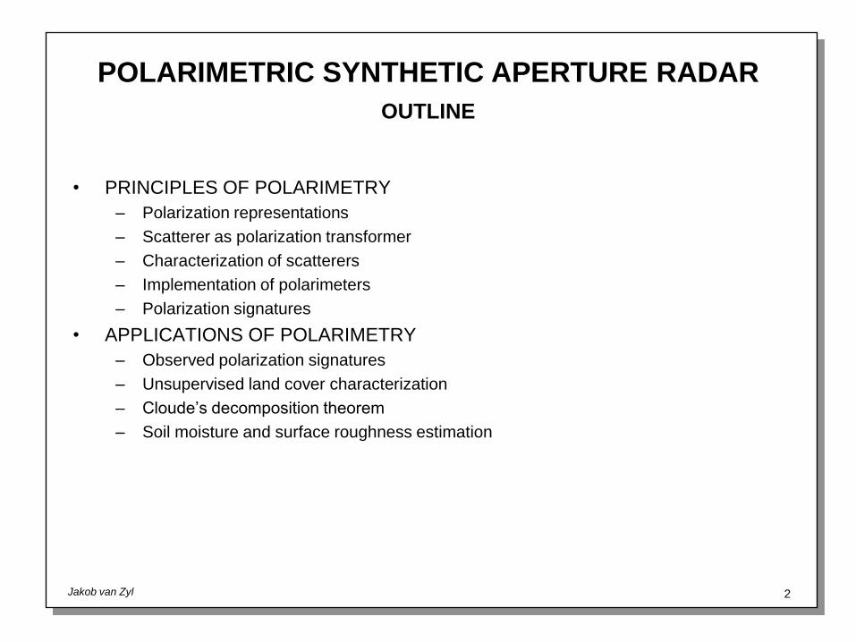
WAVE POLARIZATIONS: EXAMPLES
HORIZONTAL (LINEAR) VERTICAL (LINEAR)
RIGHT-HAND CIRCULAR LEFT-HAND CIRCULAR

POLARIMETRIC SYNTHETIC APERTURE RADAR
Jakob van Zyl 5
PRINCIPLES OF POLARIMETRY: FIELD DESCRIPTIONS
POLARIZATION VECTOR POLARIZATION ELLIPSE STOKES VECTOR
S
S0
S1
S2
S3
S0 ah2 av
2
S1 ah2
av2
S0 cos 2 cos 2
S2 2 ahav* S0 cos 2 sin 2
S3 2 ahav* S0 sin 2
, , a ah2
av2
p ah
av
v
av
ah
POLARIZATION
ELLIPSE
MAJOR
AXIS
MINOR
AXIS

POLARIMETRIC SYNTHETIC APERTURE RADAR
Jakob van Zyl 6
WAVE POLARIZATIONS: GEOMETRICAL REPRESENTATIONS
h
v
av
ah
POLARIZATION
ELLIPSE
MAJOR
AXIS
MINOR
AXIS
S2
450
S0
S3
S1
2
2
LINEAR
POLARIZATION
(HORIZONTAL)
00; 0
0
RIGHT-HAND
CIRCULAR
LEFT-HAND
CIRCULAR
450 LINEAR
POLARIZATION
(VERTICAL)
1800; 0
0
POLARIZATION ELLIPSE POINCARE SPHERE

POLARIMETRIC SYNTHETIC APERTURE RADAR
Jakob van Zyl 7
EXAMPLE POLARIZATIONS
h
v
h
v
h
v
LINEAR HORIZONTAL LINEAR VERTICAL LEFT-HAND CIRCULAR
p 1
0
p
0
1
p
1
2
1
i
00; 0
0 0
0; 45
0 90
0; 0
0
S
1
1
0
0
S
1
1
0
0
S
1
0
0
1

POLARIMETRIC SYNTHETIC APERTURE RADAR
Jakob van Zyl 8
DEFINITION OF ELLIPSE ORIENTATION ANGLES
Sometimes the polarization ellipse orientation angle is defined with respect to the
vertical direction. In that case, linear horizontal polarization has an ellipse
orientation angle of +90 degrees or -90 degrees, and linear vertical polarization
is characterized by an ellipse orientation angle of 0 degrees. Both conventions
are used in this viewgraph package.
WARNING

POLARIMETRIC SYNTHETIC APERTURE RADAR
Jakob van Zyl 9
• Transverse electromagnetic waves are characterized mathematically as 2-
dimensional complex vectors. When a scatterer is illuminated by an
electromagnetic wave, electrical currents are generated inside the scatterer.
These currents give rise to the scattered waves that are reradiated.
• Mathematically, the scatterer can be characterized by a 2x2 complex scattering
matrix that describes how the scatterer transforms the incident vector into the
scattered vector.
• The elements of the scattering matrix are functions of frequency and the
scattering and illuminating geometries.
SCATTERER AS POLARIZATION TRANSFORMER
INCIDENT WAVE
SCATTERER
SCATTERED WAVES

POLARIMETRIC SYNTHETIC APERTURE RADAR
Jakob van Zyl 10
SCATTERING MATRIX
• Far-field response from scatterer is fully characterized by four complex numbers
• Scattering matrix is also known as Sinclair matrix or Jones matrix
• Must measure a scattering matrix for every frequency and all incidence angles
Eh
Ev
sc
Shh Shv
Svh Svv
Eh
Ev
inc

POLARIMETRIC SYNTHETIC APERTURE RADAR
Jakob van Zyl 11
COORDINATE SYSTEMS
• All matrices and vectors shown in this package are measured using the
backscatter alignment coordinate system. This system is preferred when
calculating radar-cross sections, and is used when measuring them:
s
i
si
ˆ x
ˆ z
ˆ y
ˆ h t
ˆ v t
ˆ k tˆ k r
ˆ h r
ˆ v rTransmitting
AntennaReceiving
Antenna
Scatterer
POLARIMETRIC SYNTHETIC APERTURE RADAR
Jakob van Zyl 12
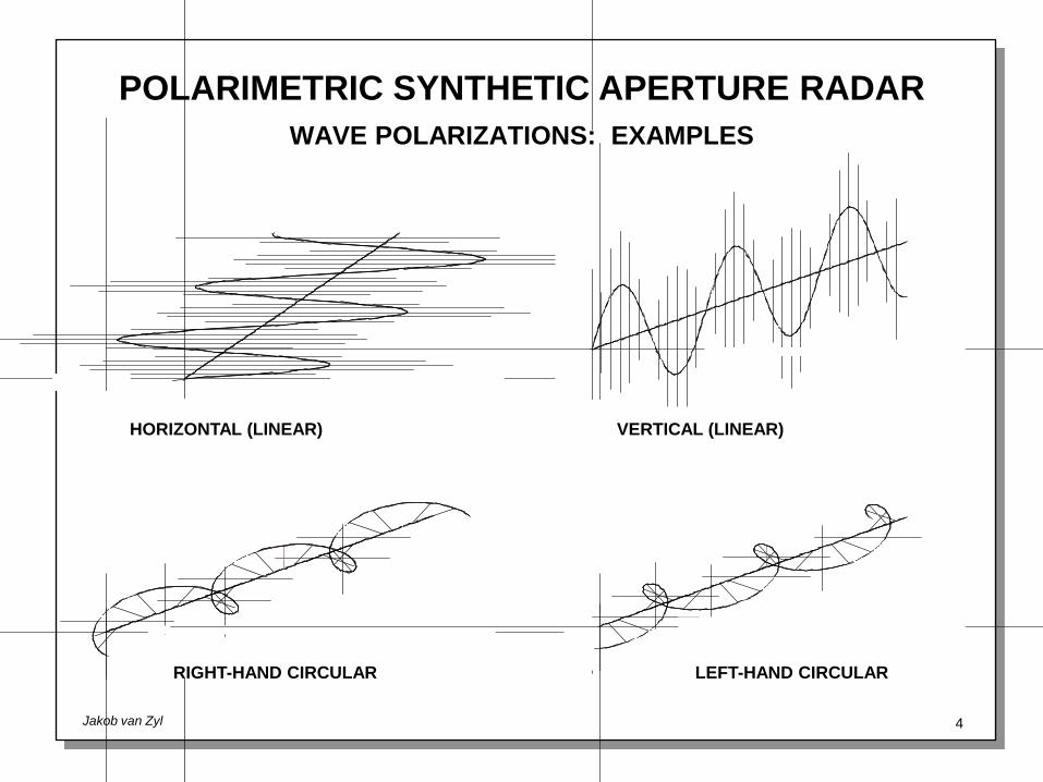
POLARIMETER IMPLEMENTATION
• To fully characterize the scatterer, one must measure the full scattering matrix:
• Setting one of the elements of the transmit vector equal to zero allows one to
measure two components of the scattering matrix at a time:
• This technique is commonly used to implement airborne and spaceborne SAR
polarimeters, such as AIRSAR and SIR-C.
Eh
Ev
rec
Shh Shv
Svh Svv
Eh
Ev
tr
Shh
Svh
Shh Shv
Svh Svv
1
0
inc
;Shv
Svv
Shh Shv
Svh Svv
0
1
inc

POLARIMETRIC SYNTHETIC APERTURE RADAR
Jakob van Zyl 13
POLARIMETER IMPLEMENTATION
TIMING
Transmission:
Horizontal
Vertical
Reception:
Horizontal
Vertical
HH HH HHHV HV
VH VV VH VV VH
Transmitter
Receiver
Receiver
BLOCK DIAGRAM
Horizontal
Vertical

POLARIMETRIC SYNTHETIC APERTURE RADAR
Jakob van Zyl 14
POLARIMETER IMPLEMENTATION
• In the implementation shown, the scattering matrix elements are measured in
pairs. The two pairs are measured at different times, i.e. from (slightly) different
viewing directions.
• Due to the speckle effect, this means that the two pairs of signals may not be
fully correlated.
• In the AIRSAR case, this decorrelation is of little consequence, since the
distance traveled by the aircraft between successive pulses (~ 50 cm) is small
compared to the system resolution (~ 2-5 m).
• In spaceborne cases, like SIR-C, the decorrelation distance is much closer in
length to the distance traveled by the antenna during the interpulse period.
Therefore, significant decorrelation could occur. This could be corrected
through resampling (interpolation) of one channel with respect to the other.

POLARIMETRIC SYNTHETIC APERTURE RADAR
Jakob van Zyl 15
MATHEMATICAL CHARACTERIZATION OF SCATTERERS:
SCATTERING MATRIX
• The radiated and scattered electric fields are related through the complex 2x2
scattering matrix:
• The (complex) voltage measured at the antenna terminals is given by the scalar
product of the receiving antenna polarization vector and the received wave
electric field:
• The measured power is the magnitude of the (complex) voltage squared:
V prec S p rad
Esc S prad
P VV* p
rec S prad
2
NOTE: Radar cross-section is proportional to power

POLARIMETRIC SYNTHETIC APERTURE RADAR
Jakob van Zyl 16
MATHEMATICAL CHARACTERIZATION OF SCATTERERS:
COVARIANCE MATRIX
• We can rewrite the expression for the voltage as follows:
• The first vector contains only antenna parameters, while the second contains
only scattering matrix elements. Using this expression in the power expression,
one finds
• The matrix is known as the covariance matrix of the scatterer
*
* * * * *;P VV AT TA ATT A A C A C TT
C
V prec S prad
phrec ph
radShh phrecpv
radShv pvrec ph
radSvh pvrecpv
radSvv
phrec ph
rad phrec pv
rad pvrec ph
rad pvrec pv
rad
Shh
Shv
Svh
Svv
˜ A T

POLARIMETRIC SYNTHETIC APERTURE RADAR
Jakob van Zyl 17
MATHEMATICAL CHARACTERIZATION OF SCATTERERS:
STOKES SCATTERING OPERATOR
• The power expression can also be written in terms of the antenna Stokes
vectors. First consider the following form of the power equation:
• The vector in the expression above is a function of the transmit antenna
parameters as well as the scattering matrix elements.
P prec E sc prec E sc *
phrecEh
sc pvrecEv
sc phrecEhsc pvrecEvsc *
phrecphrec* Eh
scEhsc* pv
recpvrec* Ev
scEvsc* ph
recpvrec* Eh
scEvsc* pv
recphrec* Ev
scEhsc*
phrecphrec*
pvrecpvrec*
phrecpvrec*
pvrecphrec*
EhscEhsc*
EvscEvsc*
EhscEvsc*
EvscEhsc*
grec X
X

POLARIMETRIC SYNTHETIC APERTURE RADAR
Jakob van Zyl 18
MATHEMATICAL CHARACTERIZATION OF SCATTERERS:
STOKES SCATTERING OPERATOR
• Using the fact that , it can be shown that can also be written as
where
• This means that the measured power can also be expressed as:
XEsc S prad
X W grad
W
ShhShh* ShvShv
* ShhShv* ShvShh
*
SvhSvh* SvvSvv
* SvhSvv* SvvSvh
*
ShhSvh* ShvSvv
* ShhSvv* ShvSvh
*
SvhShh* SvvShv
* SvhShv* SvvShh
*
P grec W g red
POLARIMETRIC SYNTHETIC APERTURE RADAR
Jakob van Zyl 19
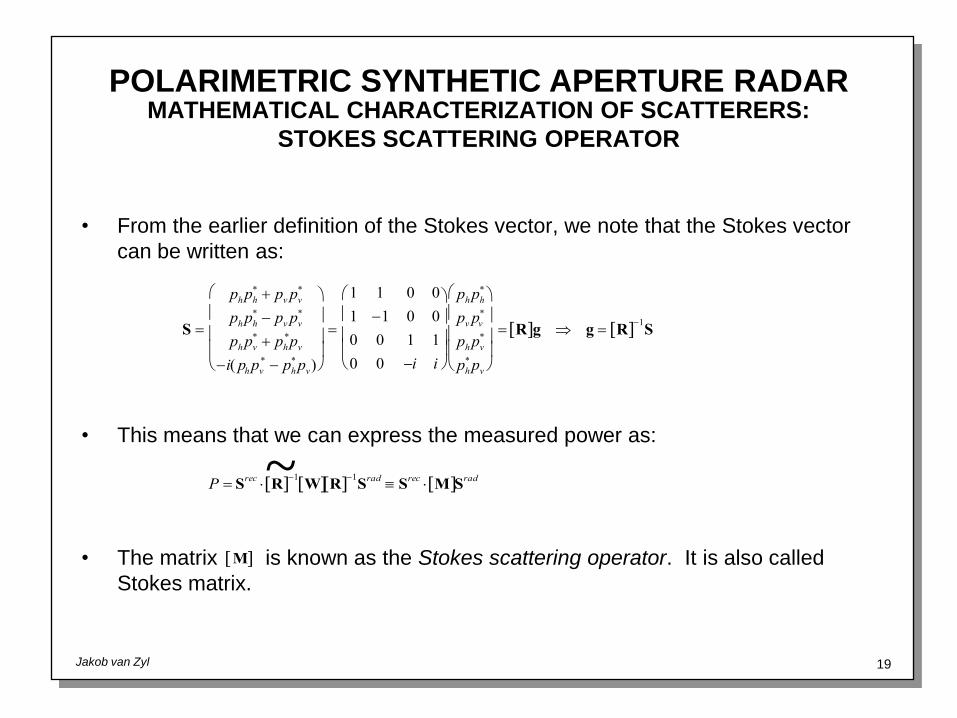
MATHEMATICAL CHARACTERIZATION OF SCATTERERS:
STOKES SCATTERING OPERATOR
• From the earlier definition of the Stokes vector, we note that the Stokes vector
can be written as:
• This means that we can express the measured power as:
• The matrix is known as the Stokes scattering operator. It is also called
Stokes matrix.
S
phph* pv pv
*
phph* pv pv
*
phpv* ph
*pv
i( phpv* ph
*pv)
1 1 0 0
1 1 0 0
0 0 1 1
0 0 i i
phph*
pv pv*
phpv*
ph*pv
R g g R 1
S
M
P Srec R
1W R
1Srad
Srec M Srad~

POLARIMETRIC SYNTHETIC APERTURE RADAR
Jakob van Zyl 20
POLARIZATION SYNTHESIS
• Once the scattering matrix, covariance matrix, or the Stokes matrix is known,
one can synthesize the received power for any transmit and receive antenna
polarizations using the polarization synthesis equations:
Scattering matrix:
Covariance Matrix:
Stokes scattering operator:
• Keep in mind that all matrices in the polarization synthesis equations must be
expressed in the backscatter alignment coordinate system.
P Srec M Srad
P A C A*
P prec S prad
2

POLARIMETRIC SYNTHETIC APERTURE RADAR
Jakob van Zyl 21
POLARIZATION SIGNATURE
• The polarization signature (also known as the polarization response) is a
convenient graphical way to display the received power as a function of
polarization.
• Usually displayed assuming identical transmit and receive polarizations (co-
polarized) or orthogonal transmit and receive polarizations (cross-polarized).
POLARIMETRIC SYNTHETIC APERTURE RADAR
Jakob van Zyl 22
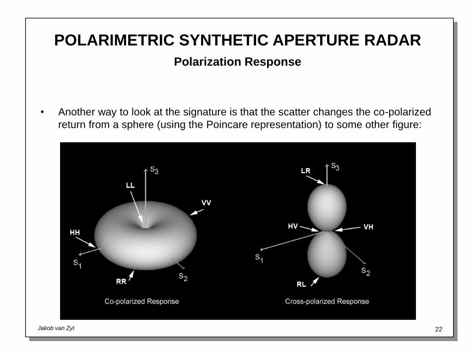
Polarization Response
• Another way to look at the signature is that the scatter changes the co-polarized
return from a sphere (using the Poincare representation) to some other figure:

POLARIMETRIC SYNTHETIC APERTURE RADAR
Jakob van Zyl 23
POLARIZATION SIGNATURE OF TRIHEDRAL CORNER REFLECTOR
S c1 0
0 1
C c
2
1 0 0 1
0 0 0 0
0 0 0 0
1 0 0 1
M 1
2c2
1 0 0 0
0 1 0 0
0 0 1 0
0 0 0 1
ˆ v t
ˆ h t
l
c k0l
2
12

POLARIMETRIC SYNTHETIC APERTURE RADAR
Jakob van Zyl 24
POLARIZATION SIGNATURE OF TRIHEDRAL CORNER REFLECTOR

POLARIMETRIC SYNTHETIC APERTURE RADAR
Jakob van Zyl 25
POLARIZATION SIGNATURE OF TRIHEDRAL CORNER REFLECTOR
Using the Stokes matrix approach, we can write the received power of the trihedral corner reflector as
P k02l4
24 21 cos2 2 cos2 2 sin2 2 cos2 2 sin2 2
k02l4
24 21 cos
22 sin2 2
k02l4
2421 cos 4
where the top sign is for the co-polarized case, and the bottom sign is for the cross-polarized case. It isimmediately apparent that the received power is independent of the ellipse orientation angle, as shownby the signatures on the previous page.
For the co-polarized case, the maximum is found when 0 , i.e. for linear polarizations, and the
minimum occurs when 450
, i.e. for circular polarizations. The positions of the maxima and minimaare reversed in the case of the cross-polarized signatures.
This behavior is explained by the fact that the reflected waves have the opposite handedness than thetransmitted ones. Therefore, if either circular polarization is transmitted, the reflected wave is polarizedorthogonally to the transmitted wave, leading to maximum reception in the cross-polarized, andminimum reception in the co-polarized case.

POLARIMETRIC SYNTHETIC APERTURE RADAR
Jakob van Zyl 26
POLARIZATION SIGNATURE OF A DIHEDRAL CORNER REFLECTOR
ˆ v t
ˆ h t
S c1 0
0 1
C c
2
1 0 0 1
0 0 0 0
0 0 0 0
1 0 0 1
M 1
2c2
1 0 0 0
0 1 0 0
0 0 1 0
0 0 0 1
2b
a
c k0ab

POLARIMETRIC SYNTHETIC APERTURE RADAR
Jakob van Zyl 27
Three-Dimensional Response

POLARIMETRIC SYNTHETIC APERTURE RADAR
Jakob van Zyl 28
POLARIZATION SIGNATURE OF A SHORT THIN CYLINDER
S c0 0
0 1
C c
2
0 0 0 0
0 0 0 0
0 0 0 0
0 0 0 1
M 1
4c2
1 1 0 0
1 1 0 0
0 0 0 0
0 0 0 0
c k02l3
3 ln 4l /a 1 ; a radius of cylinder
ˆtv
ˆth
l

POLARIMETRIC SYNTHETIC APERTURE RADAR
Jakob van Zyl 29
POLARIZATION SIGNATURE OF A SHORT THIN CYLINDER
POLARIMETRIC SYNTHETIC APERTURE RADAR
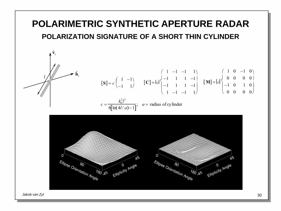
Jakob van Zyl 30
POLARIZATION SIGNATURE OF A SHORT THIN CYLINDER
S c1 1
1 1
C c
2
1 1 1 1
1 1 1 1
1 1 1 1
1 1 1 1
M c2
1 0 1 0
0 0 0 0
1 0 1 0
0 0 0 0
c k02l3
6 ln 4l / a 1 ; a radius of cylinder
ˆtv
ˆth
l
POLARIMETRIC SYNTHETIC APERTURE RADAR
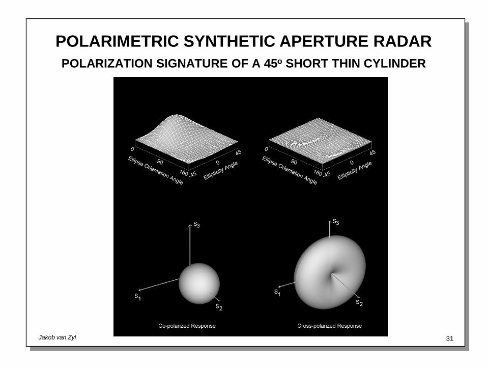
Jakob van Zyl 31
POLARIZATION SIGNATURE OF A 45o SHORT THIN CYLINDER

POLARIMETRIC SYNTHETIC APERTURE RADAR
Jakob van Zyl 32
POLARIZATION SIGNATURE OF RIGHT-HANDED HELIX
S 1
2
1 i
i 1
C
1
4
1 i i 1
i 1 1 i
i 1 1 i
1 i i 1
M 1
4
1 0 0 1
0 0 0 0
0 0 0 0
1 0 0 1
ˆ v t
ˆ h t

POLARIMETRIC SYNTHETIC APERTURE RADAR
Jakob van Zyl 33
RIGHT-HANDED HELIX

POLARIMETRIC SYNTHETIC APERTURE RADAR
Jakob van Zyl 34
POLARIZATION SIGNATURE OF LEFT-HANDED HELIX
S 1
2
1 i
i 1
C
1
4
1 i i 1
i 1 1 i
i 1 1 i
1 i i 1
M 1
4
1 0 0 1
0 0 0 0
0 0 0 0
1 0 0 1
ˆ v t
ˆ h t

POLARIMETRIC SYNTHETIC APERTURE RADAR
Jakob van Zyl 35
LEFT-HANDED HELIX

POLARIMETRIC SYNTHETIC APERTURE RADAR
Jakob van Zyl 36
SCATTERING MODELS AND
OBSERVATIONS

POLARIMETRIC SYNTHETIC APERTURE RADAR
Jakob van Zyl 37
Signatures

POLARIMETRIC SYNTHETIC APERTURE RADAR
Jakob van Zyl 38
Rough Surface Scattering - Roughness

POLARIMETRIC SYNTHETIC APERTURE RADAR
Jakob van Zyl 39
Rough Surface Scattering – Dielectric Constant

POLARIMETRIC SYNTHETIC APERTURE RADAR
Jakob van Zyl 40
Surface Characteristics – Geometrical Properties

POLARIMETRIC SYNTHETIC APERTURE RADAR
Jakob van Zyl 41
Surface Characteristics – Dielectric Properties
0
5
10
15
20
25
30
35
40
45
0 0.1 0.2 0.3 0.4 0.5
Volumetric Soil Moisture
Rea
l Pa
rt of Ep
silon
Hallikainen
Wang and Schmugge
Brisco et al
Dobson et al.

POLARIMETRIC SYNTHETIC APERTURE RADAR
Jakob van Zyl 42
POLARIZATION SIGNATURE OF SINGLE SHORT THIN CYLINDER
S c0 0
0 1
C c
2
0 0 0 0
0 0 0 0
0 0 0 0
0 0 0 1
M 1
4c2
1 1 0 0
1 1 0 0
0 0 0 0
0 0 0 0
c k02l3
3 ln 4l /a 1 ; a radius of cylinder
ˆtv
ˆth
l

POLARIMETRIC SYNTHETIC APERTURE RADAR
Jakob van Zyl 43
SHORT CYLINDERS ORIENTED COSINE SQUARED AROUND
VERTICAL

POLARIMETRIC SYNTHETIC APERTURE RADAR
Jakob van Zyl 44
THIN CYLINDERS ORIENTED UNIFORMLY RANDONLY

POLARIMETRIC SYNTHETIC APERTURE RADAR
Jakob van Zyl 45
MODEL OF VEGETATION SCATTERING
Vegetation Layer
Ground Surface
, , , ,p p p p pa l p
, , , ,s s s s sa l p
, , ,g g lh l s
b

POLARIMETRIC SYNTHETIC APERTURE RADAR
Jakob van Zyl 46
SCATTERING MECHANISMS
i
i
ii
b
2
z
3
4 1
POLARIMETRIC SYNTHETIC APERTURE RADAR
Jakob van Zyl 47
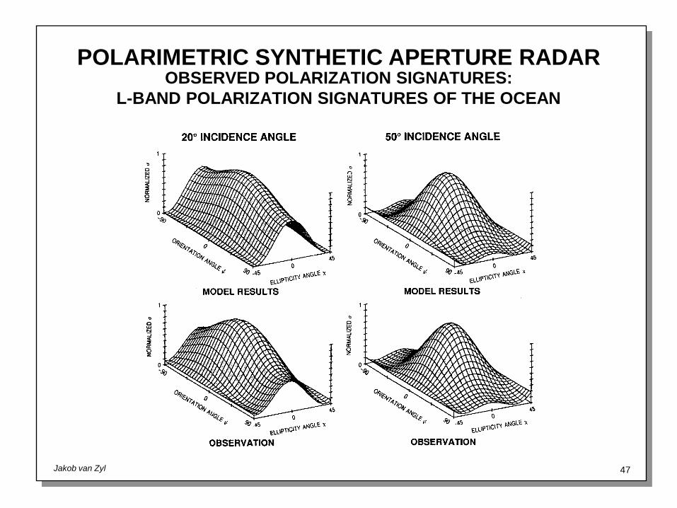
OBSERVED POLARIZATION SIGNATURES:
L-BAND POLARIZATION SIGNATURES OF THE OCEAN
POLARIMETRIC SYNTHETIC APERTURE RADAR
Jakob van Zyl 48
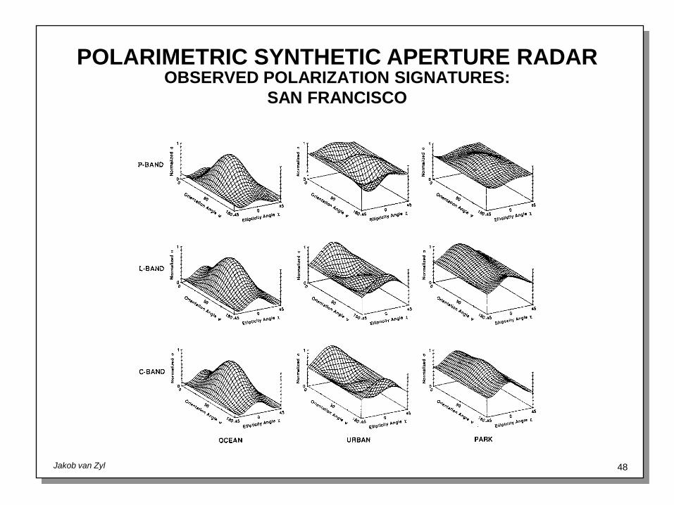
OBSERVED POLARIZATION SIGNATURES:
SAN FRANCISCO

POLARIMETRIC SYNTHETIC APERTURE RADAR
Jakob van Zyl 49
OBSERVED POLARIZATION SIGNATURES:
SAN FRANCISCO
At each frequency the ocean area scatters in a manner consistent with models of slightly roughsurface scattering, the urban area like a dihedral corner reflector, while the park and natural terrainregions scatter much more diffusely, that is, the signatures possess large pedestals. This indicatesthe dominant scattering mechanisms responsible for the backscatter for each of the targets. Theocean scatter is predominantly single bounce, slightly rough surface scattering. The urban regionsare characterized by two-bounce geometry as the incident waves are twice forward reflected fromthe face of a building to the ground and back to the radar, or vice versa. The apparent diffusenature of the backscatter from the park and natural terrain indicates that in vegetated areas thereexists considerable variation from pixel to pixel of the observed scattering properties, leading to thehigh pedestal. This variation may be due to multiple scatter or to a distinct variation in dominantscattering mechanism between 10m resolution elements.
POLARIMETRIC SYNTHETIC APERTURE RADAR
Jakob van Zyl 50
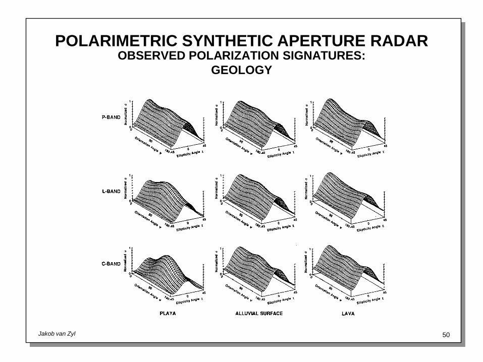
OBSERVED POLARIZATION SIGNATURES:
GEOLOGY
POLARIMETRIC SYNTHETIC APERTURE RADAR
Jakob van Zyl 51
OBSERVED POLARIZATION SIGNATURES:
GEOLOGY
The previous viewgraph shows polarization signatures extracted from an AIRSAR image of thePisgah lava flow in California. Signatures correspond to the flow itself (a very rough surface), analluvial fan (medium roughness), and from the playa next to the flow (a very smooth surface). Notethat as the roughness of the surface increases, so does the observed pedestal height. This is quiteconsistent with the predictions of the slightly rough surface models, even though the surface r.m.s.heights exceed the strict range of validity of the model. The exception is the playa case, where thepedestal at P-band is higher than that at L-band. Possible explanations for this behavior includesubsurface scattering due to increased penetration at P-band, or signal-to-noise limitations for thevery smooth surface.

POLARIMETRIC SYNTHETIC APERTURE RADAR
Jakob van Zyl 52
OBSERVED POLARIZATION SIGNATURES:
SEA ICE

POLARIMETRIC SYNTHETIC APERTURE RADAR
Jakob van Zyl 53
OBSERVED POLARIZATION SIGNATURES:
SEA ICE
Note the pedestal height as a function of frequency for the multi-year ice - the P-band pedestal isquite small, while the C-band pedestal is the greatest of the three. For the first year ice, exactly theopposite behavior is seen. The P-band signature shows the highest and the C-band signature thelowest pedestal. The multi-year ice behavior may be explained if we consider the ice to be formedof two layers, where the upper layer consists of randomly oriented oblong inclusions about the sizeof a C-band wavelength, several centimeters. The lower layer forms a solid, but slightly roughsurface. In this situation the C-band signal would interact strongly with the diffuse scattering upperlayer, giving rise to the high pedestal. The longer wavelength L- and P-band signals would passthrough the upper and be scattered by the lower layer, which is smooth enough to exhibit fairlypolarized backscatter. On the other hand, similar characteristics are also observed for simplerough surface scattering also, as previously explained.
At present we have no model to explain the first year ice behavior.