
Chapter 20 Electric Circuits. A battery consists of chemicals, called electrolytes, sandwiched in...
43
Chapter 20 Electric Circuits
-
Upload
elizabeth-woods -
Category
Documents
-
view
218 -
download
3
Transcript of Chapter 20 Electric Circuits. A battery consists of chemicals, called electrolytes, sandwiched in...
Chapter 20
Electric Circuits

• A battery consists of chemicals, called electrolytes, sandwiched in between 2 electrodes, or terminals, made of different metals.
• Chemical reactions do work to separate charge, which creates a potential difference between positive and negative terminals
• A physical separator keeps the charge from going back through the battery.
The Battery

ε and ∆V• For an ideal battery
potential difference between the positive and negative terminals, ∆V, equals the chemical work done per unit charge.
∆V = Wch /q = ε• ε is the emf of the battery• Due to the internal
resistance of a real battery, ∆V is often slightly less than the emf.

How do we know there is a current?

20.1 Electromotive Force and Current
The electric current is the amount of charge per unit time that passesthrough a surface that is perpendicular to the motion of the charges.
t
qI
One coulomb per second equals one ampere (A).

20.1 Electromotive Force and Current
If the charges move around the circuit in the same direction at all times,the current is said to be direct current (dc).
If the charges move first one way and then the opposite way, the current is said to be alternating current (ac).

EOC #3A fax machine uses 0.110 A of current in its normal mode
of operation, but only 0.067 A in the standby mode. The machine uses a potential difference of 120 V.
(a)In one minute (60 s!), how much more charge passes through the machine in the normal mode than in the standby mode?
(b)How much more energy is used?
EOC #3A fax machine uses 0.110 A of current in its normal mode
of operation, but only 0.067 A in the standby mode. The machine uses a potential difference of 120 V.
(a)In one minute (60 s!), how much more charge passes through the machine in the normal mode than in the standby mode? 2.6 C
(b)How much more energy is used? 310 J
20.1 Electromotive Force and Current
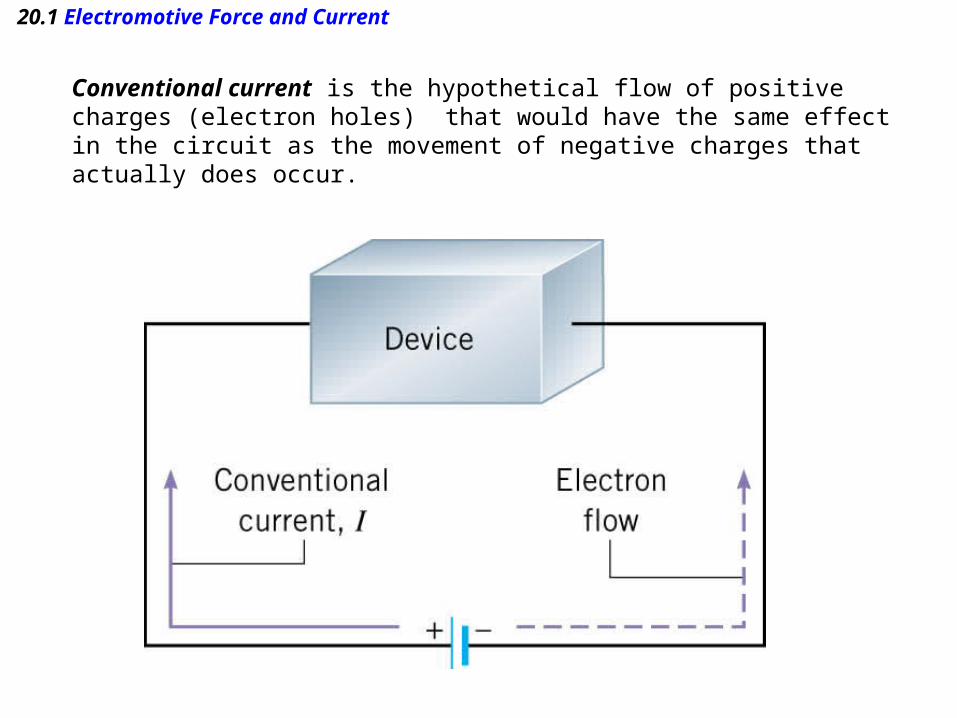
Conventional current is the hypothetical flow of positive charges (electron holes) that would have the same effect in the circuit as the movement of negative charges that actually does occur.

20.2 Ohm’s Law
The resistance (R) is defined as the ratio of the voltage V applied across a piece of material to the current I throughthe material.

20.2 Ohm’s Law
OHM’S LAW
The ratio V/I is a constant, where V is thevoltage applied across a piece of mateiraland I is the current through the material:
SI Unit of Resistance: volt/ampere (V/A) = ohm (Ω)
IRVRI
V or constant

20.2 Ohm’s Law
To the extent that a wire or an electrical device offers resistance to electrical flow,it is called a resistor.

20.2 Ohm’s Law
Example 2 A Flashlight
The filament in a light bulb is a resistor in the formof a thin piece of wire. The wire becomes hot enoughto emit light because of the current in it. The flashlightuses two 1.5-V batteries to provide a current of0.40 A in the filament. Determine the resistance ofthe glowing filament.
5.7A 0.40
V 0.3
I
VR

Eoc #4
Suppose that the resistance between the walls of a biological cell is 1.00 x 10¹⁰ Ω.
(a)What is the current when the potential difference between the walls is 95 mV?
(b)If the current is composed of Na+ ions (q = +e), how many such ions flow in 0.2 s?

Eoc #4
Suppose that the resistance between the walls of a biological cell is 1.00 x 10¹⁰ Ω.
(a)What is the current when the potential difference between the walls is 95 mV? 9.5 x 10⁻¹² A
(b)If the current is composed of Na+ ions (q = +e), how many such ions flow in 0.2 s? 1.19 x 10⁷

Ratio Reasoning using Ohm’s LawIn circuit #1, the battery has twice as much potential
difference as the battery in circuit #2. However, the current in circuit # 1 is only ½ the current in circuit #2. Therefore R1 is________ the resistance R2
:A. twice D. four timesB. one half E. 1/4 C. equal to

20.4 Electric Power
IVP
ELECTRIC POWER•Charges acquire EPE due to the potential difference across the battery. In the circuit, this energy is transformed into KE, as the charges move.•The rate at which energy is delivered is Power.
P = Energy/∆t •When there is current in a circuit as a result of a potential, the electric power delivered to the circuit is:
SI Unit of Power: watt (W), where one watt equals one joule per second
Many electrical devices are essentially resistors, so we use 2 formulas for power based on resistance. From Ohm’s Law:
RIIRIP 2
R
VV
R
VP
2
20.4 Electric Power
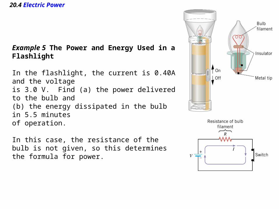
Example 5 The Power and Energy Used in aFlashlight
In the flashlight, the current is 0.40A and the voltageis 3.0 V. Find (a) the power delivered to the bulb and(b) the energy dissipated in the bulb in 5.5 minutesof operation.
In this case, the resistance of the bulb is not given, so this determines the formula for power.

20.4 Electric Power
(a)
(b)
W2.1V 0.3A 40.0 IVP
J100.4s 330 W2.1 2 tPE

Power in a circuit
Through which resistor is the most power dissipated?
A. b B. bd C. d D. a

Power rating of a household applicance
• Commercial and residential electrical systems are set up so that each individual appliance operates at a potential difference of 120 V.
• Power Rating or Wattage is the power that the appliance will dissipate at a potential difference of 120 V (e.g. 100 W bulb, 1000 W space heater).
• Power consumption will differ if operated at any other voltage.
• Energy is often expressed as kilowatt-hours, for metering purposes.

kW-h
How much energy in a kilowatt-hour?
A)1000 Joules
B)0.28 Joules
C)3.6 million Joules
D)60,000 Joules

Resistors in Series• Series wiring means that the resistors are connected so that there is
the same current through each resistor.• The potential difference through each resistor is :
|∆VR |= IR• The equivalent resistor (Rs ) is made by adding up all resistors in
series in the circuit.∆Vbat = |∆Vcircuit |= IRs

20.6 Series Wiring
•By understanding that the potential difference across any circuit resistor will be a voltage DROP, while the potential difference back through the battery (charge escalator) will be a GAIN, one can replace the ΔV with “V” , and dispense with the absolute value signs
V1 (voltage drop across the resistor1) = IR1
V2 (voltage drop across the resistor2) = IR2
Vbat = Vcir = IReq

20.6 Series Wiring
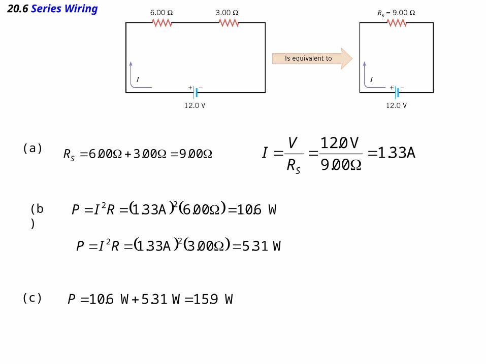
Resistors in a Series Circuit
A 6.00 Ω resistor and a 3.00 Ω resistor are connected in series witha 12.0 V battery. Assuming the battery contributes no resistance to the circuit, find (a) the current, (b) the power dissipated in each resistor,and (c) the total power delivered to the resistors by the battery.
20.6 Series Wiring
(a)
(b)
(c)
00.9 00.3 00.6SR A 33.1 00.9
V 0.12
SR
VI
W6.10 00.6A 33.1 22 RIP
W31.5 00.3A 33.1 22 RIP
W9.15 W31.5 W6.10 P

Series ResistorsWhat is the value of R (3rd resistor in circuit)?
a. 50 Ω b. 25Ω c. 10 Ω d. 0

20.7 Parallel Wiring
Parallel wiring means that the devices areconnected in such a way that the same voltage is applied across each device.
When two resistors are connected in parallel, each receives current from the battery as if the other was not present.
Therefore the two resistors connected inparallel draw more current than does eitherresistor alone.

20.7 Parallel Wiring

20.7 Parallel Wiring
The two parallel pipe sections are equivalent to a single pipe of thesame length and same total cross sectional area.

20.7 Parallel Wiring
PRV
RRV
R
V
R
VIII
111
212121
parallel resistors
321
1111
RRRRP
note that for 2 parallel resistors this equation is equal to :
Rp = (R1R2 ) / (R1 + R2)

20.7 Parallel Wiring
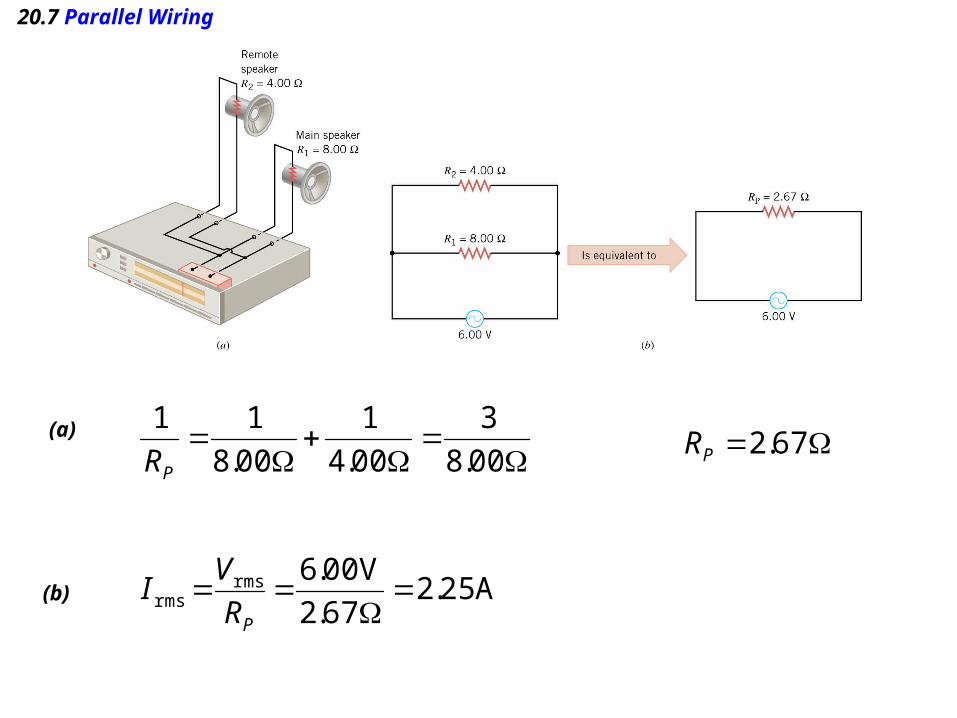
Example 10 Main and Remote Stereo Speakers
Most receivers allow the user to connect to “remote” speakers in additionto the main speakers. At the instant represented in the picture, the voltageacross the speakers is 6.00 V. Determine (a) the equivalent resistanceof the two speakers, (b) the total current supplied by the receiver, (c) thecurrent in each speaker, and (d) the power dissipated in each speaker.
20.7 Parallel Wiring
(a)
00.8
3
00.4
1
00.8
11
PR 67.2PR
(b) A 25.2 67.2
V 00.6rmsrms
PR
VI

20.7 Parallel Wiring
A 750.0 00.8
V 00.6rmsrms
R
VI(c) A 50.1
00.4
V 00.6rmsrms
R
VI
(d) W50.4V 00.6A 750.0rmsrms VIP
W00.9V 00.6A 50.1rmsrms VIP

Circuits Wired Partially in Series and Partially in ParallelExample 12
Find a) the total current supplied by the the battery and b) the voltage dropbetween points A and B.

Circuits Wired Partially in Series and Partially in ParallelExample 12
Find a) the total current supplied by the the battery and b) the voltage dropbetween points A and B.

Circuits Wired Partially in Series and Partially in ParallelExample 12
a) Itot = V/Rp = 24V/240Ω = .10Ab) now go back to the 1st circuit in part c to
calculate the voltage drop across A-B:VAB = IRAB = (.10A)(130 Ω) = 13V

Your Understanding
• What is the ratio of the power supplied by the battery in parallel circuit A to the power supplied by the battery in series circuit B?
a.¼ c. 2 e. 1
b. 4 d. 2
A.
B.
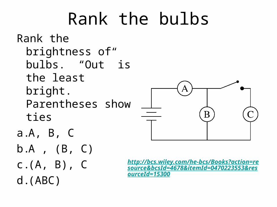
Rank the bulbsRank the brightness
of bulbs. “Out” is the least bright. Parentheses show ties
a.A, B, C
b.A , (B, C)
c.(A, B), C
d.(ABC)http://bcs.wiley.com/he-bcs/Books?action=resource&bcsId=4678&itemId=0470223553&resourceId=15300
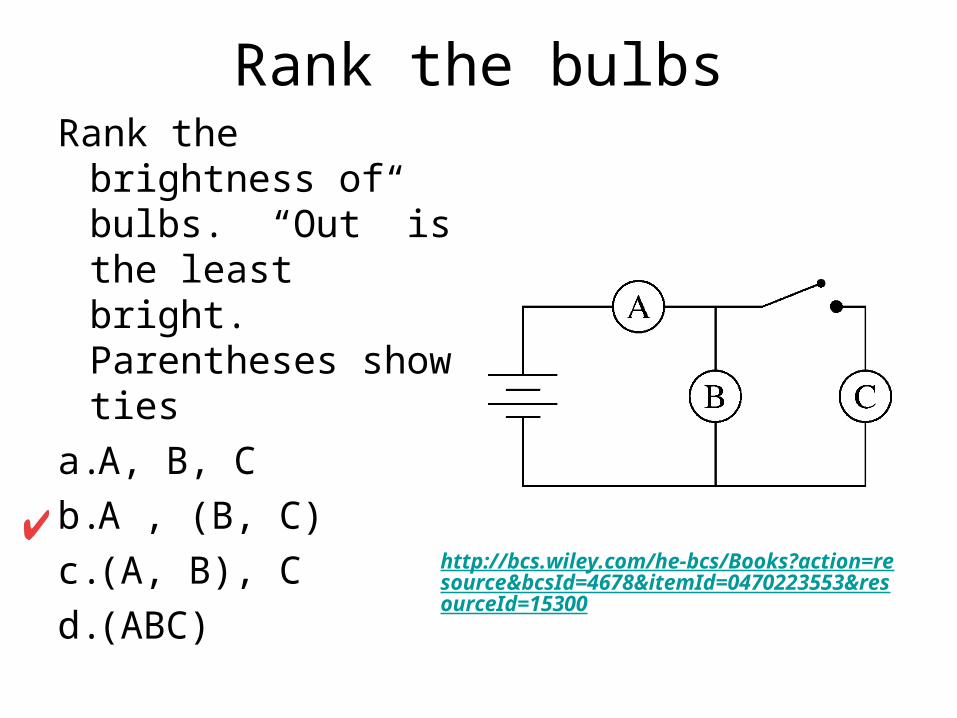
Rank the bulbsRank the brightness
of bulbs. “Out” is the least bright. Parentheses show ties
a.A, B, C
b.A , (B, C)
c.(A, B), C
d.(ABC)http://bcs.wiley.com/he-bcs/Books?action=resource&bcsId=4678&itemId=0470223553&resourceId=15300

Switch closed
How does A’s brightness compare with when the switch was open?
a.A gets brighter
b.A gets dimmer
c.A stays the same
Use Ohm’s Law and then look at sim 33, Ch 20, link at right.
http://bcs.wiley.com/he-bcs/Books?action=resource&bcsId=4678&itemId=0470223553&resourceId=15300
closed

20.11 The Measurement of Current and Voltage
An ammeter must be inserted intoa circuit so that the current passesdirectly through it.The resistance of the ammeter changes the current through the circuit.The ideal ammeter has a very low resistance
20.11 The Measurement of Current and Voltage
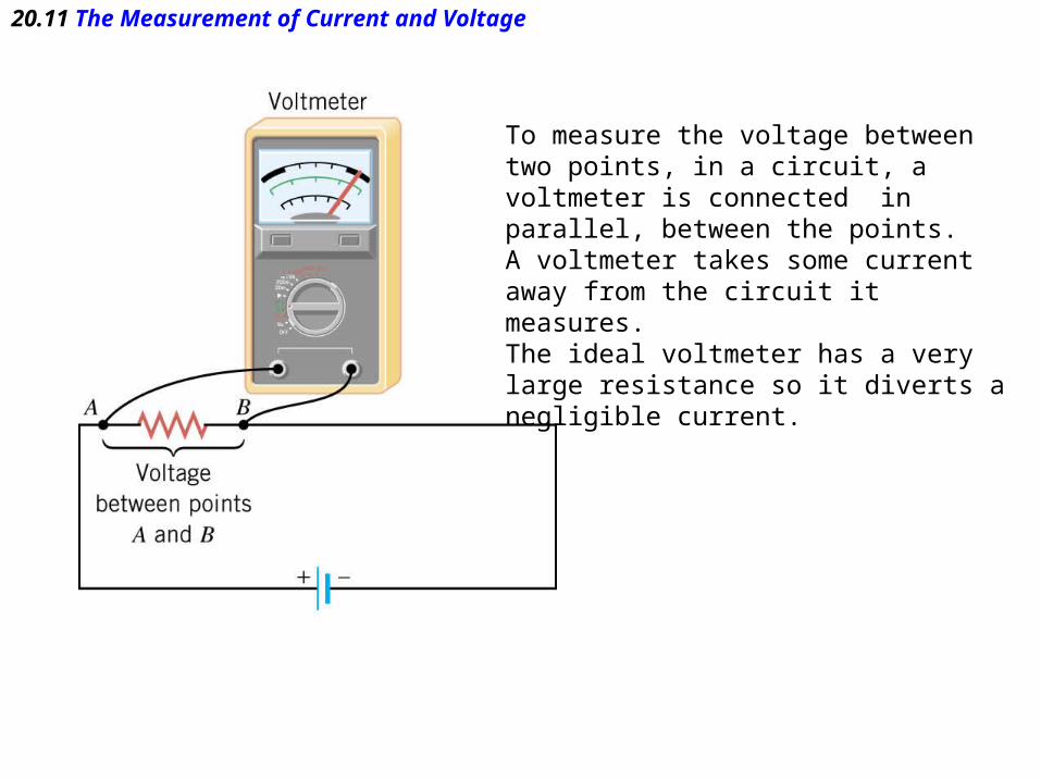
To measure the voltage between two points, in a circuit, a voltmeter is connected in parallel, between the points.A voltmeter takes some current away from the circuit it measures.The ideal voltmeter has a very large resistance so it diverts a negligible current.

![Organic Biomimicking Memristor for Information …or.nsfc.gov.cn/bitstream/00001903-5/302849/1/...[ 20,33–35 ] Sandwiched between two metal electrodes, the EV(ClO 4) 2 /BTPA-F bilayer](https://static.fdocuments.in/doc/165x107/5ace49457f8b9ab10a8ea78d/organic-biomimicking-memristor-for-information-ornsfcgovcnbitstream00001903-53028491.jpg)