
ARCHITECTURE SANDWICHED
61
ARCHITECTURE SANDWICHED Tuning anisotropy through variable thickness and hetereogeneous laminar assemblies. by Nazareth Ekmekjian Bachelor ofArchitecture Southern California Institute of Architecture (SCI-Arc) 2008 Submitted to the Department ofArchitecture on May 21st, 2015 in Partial Fulfillment of the Requirements for the Degree of Master of Science in Architecture Studies at the MASSACHUSETTS INSTITUTE OF TECHNOLOGY June 2015 2015 Nazareth Ekmekjian. All rights reserved. The author hereby grantspermission to reproduce and to distribute publicly paper and electronic copies of this thesis document in whole or in part in any medium now known or hereafter created ARCHIVES MASSACHUSETTS INSTITUTE OF fl-CHNOLULGY JUL 01 2015 LIBRARIES Signature of Author. Certified by......... Certified by......... Accepted by....... Signature redacted S ignature redact Department of Architecture May 21, 2015 Brandon Clifford $eitsii Lecturer, Department of Architecture, MIT u rThesis Supervisor Signature redacted Mark Goulthorpe Associate Prof ssor, Department of Architecture, MIT Thesis Supervisor Signature redacted Takehiko Nagakura Chair of the Department Committee on Graduate Students, MIT 1
Transcript of ARCHITECTURE SANDWICHED

ARCHITECTURE SANDWICHEDTuning anisotropy through variable thickness and hetereogeneous laminar assemblies.
by
Nazareth EkmekjianBachelor ofArchitecture
Southern California Institute of Architecture (SCI-Arc) 2008
Submitted to the Department ofArchitecture on May 21st, 2015in Partial Fulfillment of the Requirements for the Degree of
Master of Science in Architecture Studies
at the
MASSACHUSETTS INSTITUTE OF TECHNOLOGYJune 2015
2015 Nazareth Ekmekjian. All rights reserved.
The author hereby grants permission to reproduce and to distributepublicly paper and electronic copies of this thesis document inwhole or in part in any medium now known or hereafter created
ARCHIVESMASSACHUSETTS INSTITUTE
OF fl-CHNOLULGY
JUL 01 2015
LIBRARIES
Signature of Author.
Certified by.........
Certified by.........
Accepted by.......
Signature redacted
S ignature redactDepartment of Architecture
May 21, 2015
Brandon Clifford$eitsii Lecturer, Department of Architecture, MIT
u rThesis SupervisorSignature redacted
Mark GoulthorpeAssociate Prof ssor, Department of Architecture, MIT
Thesis SupervisorSignature redacted
Takehiko NagakuraChair of the Department Committee on Graduate Students, MIT
1

ARCHITECTURE SANDWICHEDTuning anisotropy through variable thickness and hetereogeneous laminar assemblies.
Thesis Committee:
Thesis AdvisorBrandon CliffordBeluschi Lecturer, Department of Architecture, MIT
Thesis AdvisorMark GoulthorpeAssociate Professor, Department of Architecture, MIT
Thesis ReaderNader TehraniProfessor, Department of Architecture, MIT
2

ARCHITECTURE SANDWICHEDTuning anisotropy through variable thickness and hetereogeneous laminar assemblies.
by
Nazareth EkmekjianSubmitted to the Department ofArchitecture on May 21st, 2015
in Partial Fulillment ofthe Requirements for the Degree ofMaster of Science in Architecture Studies
AbstractMuch of architecture's earliest material palettes and construction methods are often referred totoday as legacy materials - those primarily consisting of various types of stone and masonryconstruction. While these materials are often conceptually thought of as being solid, monolithic,and even homogeneous, in actuality they rely on logics of assembly more akin to contemporarysandwich structures, which are laminar assemblies typically composed of two or more stressedskins and either a solid or cellular core that binds them together. While it is still common touse ancient materials in contemporary architecture, the construction methods and techniques usedseveral hundred years ago are no longer appropriate for today's buildings. This thesis however,argues for a newfound relevance of their influence on contemporary and even future materialselections and methods.
Specifically, this thesis explores the potentials of composite sandwiches varying in thickness andmaterial in search of architectural possibilities whose structural, formal, and aesthetic implicationsare a result of tuning multiple influences. Variable thickness is used here as a strategy for enablinga range of architectural and tectonic conditions, all within the same heterogeneous but integratedlaminar assemblies. While most commercial products in the realm of composite sandwichesare of uniform thickness in section, this thesis suggests a method for constructing sandwichedelements with variable thickness. This is done primarily through a process of infill and backfillusing expanding urethane foam as a medium which creates the so called "core" of the sandwichbetween two skins. This investigation works through a series of small scale prototypes, each ofwhich focus on a particular tectonic, spatial, or structural condition. These mock ups are meantto serve as didactic artifacts, providing feedback with which to incorporate and speculate uponlarger architectural propositions through drawing and representation. The end result is a set ofarchitectural proposals which suggest the beginnings of new design methodologies.
Thesis AdvisorBrandon CliffordBeluschi Lecturer, Department of Architecture, MIT
Thesis AdvisorMark GoulthorpeProfessor, Department of Architecture, MIT
3

Acknowledgements
This thesis would not have been possible without the support offamily and friends, near and from afar, who have always encouragedme to do what I love.
Thank you to my advisors, Brandon Clifford and Mark Goulthorpefor your insights, suggestions, and for challenging me to pursue myideas through writing and built form. Brandon, it's been a pleasureworking with you from my first semester in Volumetric Roboticsto the completion of this thesis. Mark, your wealth of knowledgeand resources in composite materials, and critical thinking hasbenefitted me immensely. Thank you for sharing your experiencesand introducing me to the experts in Rhode Island.
Thank you, Nader! You've been extremely welcoming to me wellbefore Day 1 and have continued to do so till now. Working withyou professionally and academically has been a great pleasure andin fact has not felt like work at all. I have learned a great deal fromyou.
Thank you to the Department of Architecture at MIT for yourfinancial support and facilities. Thank you to John Fernandez andthe IDC for your support and resources which have played a hugerole in the production of various prototypes throughout my timehere. Thank you also to David Costanza for sharing your knowledgeand expertise with me.
Big thanks to Carrie, Madeline, Jeff, Gabriel, David and the entireSMArchS team for all the laughs, adventures, and all around goodtimes over the last two years. Here's to many more!
I'd also like to thank Eric Kahn, my first studio instructor at SCI-Arc,who passed away nearly a year ago. Eric, while you were not directlyinvolved in any of the work in this thesis, your energy, creativity,and spirit has always been with me throughout the duration of mytime here.
Lastly I'd like to thank my father who moved to the U.S. nearly 30years ago and swung a hammer in order to provide the opportunitiesfor me to achieve greater things. Spending time with you onconstruction sites has undoubtedly influenced my desire to comethis far. Mom, you know how much I love you too! Thank you foralways being there for me regardless of circumstance.
4

Table of Contents
Acknowledgements
Background
Introduction2.1 Historic References2.2 Sandwich Structures
Methods3.1 Mold Making3.2 Vacuum Bagging3.3 Infilling / Backfifling
Results
Speculations & Projections5.1 Small Scale Testing5.2 Architectural Propositions5.3 Future Research
Bibliography
5
Abstract 03
04
07
0915
1.0
2.0
3.0
4.0
5.0
6.0
182532
42
454657
58

1.0 Background
6

1.0 Background
Apart from visits to manufacturing facilities and construction sites, industry collaborations, and
catalogue-based specifications, architects for the most part have historically remained disconnected
from direct, material-driven making. Standardized architectural practice often operates in a
relatively linear sequence of processes beginning with conception, through representation, towards
development, eventually leading to actualization (although this sequence may often be cyclical in
nature until the thing is completed). Regardless, even within this practice, it is specifically the act
of architectural representation itself that tends to be the dominating mode for design production,
at least prior to construction.
In recent years, a handful of contemporary practitioners and theorists have alleged the disappearance
of the orthographic architectural drawing, for reasons related to the obsolescence of its technical
apparatus; stating it has been replaced by post-orthographic, electro-topological models which
contain within them "all possible future object scenarios." These include but are not limited to
metrics surrounding energy consumption, tectonic specifications, maintenance costs, etc. This is
nothing new to us. In fact, it has become the new standard by which many practitioners now
operate.
Yet no matter how advanced, robust, or capable our various new representational apparatus have
become, the fact remains that they still operate independently from the material manifestations
which they aim to determine and realize. The very act of representation itself is an altogether distinct
act from that of making. Let us for a moment consider the basis of the claims made surrounding the
disappearance of orthographic architectural drawing and its replacements. At its core, it is simply
the means and methods used to produce drawings and information which are being cited as the
reasons for its non-existence. Thinking through this, we might say that architecture is as much a
product of its means and methods as it is the conceptual, economic, regional, and cultural forces
that shape it.
7

2.0 Introduction
8

2.0 Introduction
2.1 HISTORIC REFERENCES
The term poche in architecture refers to a representational technique used to describe moments
of uninhabitable solid mass in section. This typically includes elements of a building that make
up the envelope and any other spatial partitions, such as floor, ceiling, walls, etc. The concept of
poche in architecture is one of the oldest disciplinary conventions, made apparent in the widest
range of works from ancient temples to contemporary buildings. While it is commonly attributed
to methods of making surrounding volumetric masonry construction dating as far back to Greek
temples, we insist on continuing to use it to describe moments of section in today's buildings
regardless of construction method. However, to be clear, the use of the word poche here is intended
to suggest variability in thickness and material.
When working with extremely thick materials, such as masonry or even cast concrete, there
lies the opportunity for variation or difference between interior and exterior spatial conditions.
However when the shift towards lighter, thinner, industrialized materials took place our building
envelopes allowed for a liberalization of spatial and programmatic constraints - as evidenced by
modernism. Thinking through this 'in section' allows us to consider these implications as a result
of the materials themselves which are used to produce the buildings. More often than not, we
witness variable thickness (but not variable material) in 'the ancients' - masonry and stereotomic
construction - while we witness the contrary in 'the modern': variable material but not variable
thickness.
The following are 9 cathedrals from the 1600's - 1700's drawn in terms of figure ground, to focus
on the relationship between interior/exterior through variation in material thickness which produce
conditions of anisotropy or difference. The thickness of their envelopes is partly the result of the
materials and methods used to construct them - specifically stone and masonry.
9

o ~
* Abbey Church of Santa Anna, Munich
* St. Mary Woolnoth, London 1727
* Church of St. Lorenzo, Turin 1687
* Monestary Church, Walstatt 1733
* Chapel St. Luigi, Corteranzo 1700's
4 Parish Church, Gailbach
* Church of the Imaculate Conception, Guarini
* Pilgrimage Church, Krtiny 1750
* Castle Chapel of the Epiphany, Smirice 1711
coo0 00
44
fd.5#ol
"%
T-
10
1100" 9

CD
1EF
0
I K
* Beijing National Aquatics Center (Watercube), Beijing 2003
Chapel of Ronchamp, 1957
Ingalls Building, Cincinati OH 1903
* Glass Pavilion at Toledo Museum of Art, Toledo OH 2006
Porta Fira Towers, Barcelona 2009
Lake Shore Drive Apartments, Chicago 1951
Villa Savoye, Poissy, France 1931
Leonardo Glass Cube, Bad Driburg, Germany 2007
Glass House, New Canaan CT 1949
11
I U
...0. ..
......
0
*1
K,
* U
* U U
I U U
1
m
PN1

0 __
0
0 0
0
0
Matrix constructed of 9 different instances of a parametric model, which controls the depth of
corrugated profiles. Top row shows upper profile, middle shows bottom profile, and bottom
row shows both. This allows for fine tuning of geometry for structural performance and surface
articulation.
12

The previous drawings are 9 modernist and contemporary buildings also drawn in terms of figure
ground. There are two main things worth pointing out. One is the extreme difference in thickness
of envelope compared to the cathedrals, and the other is the clarity of their structural systems as
evidenced by the inclusion of recognizable building elements such as I-Beams, columns and so on.
While the cathedrals also rely on the use of columns (and other structural systems like arches) to
support themselves, when we look at them in plan we often find them hidden in the poche of the
envelope, whereas here they're quite visible.
As technologies in the building industry increased over time, the thickness of building envelopes
has decreased, resulting in progressively thinner sections of lighter weight material assemblies.
This progression is evidenced by the advent of numerous industrialized processes bringing forth a
wide array of primarily sheet-based, standardized building materials. Common examples include
plywood, drywall, and sheet metals, even steel and lumber. From an engineering point of view,
such advancements yield the production of lighter buildings, eliminating excessive weight and
reducing material consumption; all great proponents of efficiency. However in the broader context
of design, such a transition from thick volumetric materials to thinner industrialized materials
seems to have also diminished our ability to construct variation between the interior and exterior.
In the interest of clarity and specificity, it's important to distinguish different logics and types of
material formation and assembly. This is critical to note here, as some materials are able to be
more clearly represented and therefore accounted for than others simply due to the nature of their
composition. For instance, the dimensional and morphological properties of some industrialized
materials - such as plywood, lumber, and steel - are more stable and therefore easily representable
than those of, say, textile based composites and industrial foams or resins. The latter class of
materials could be described as being more amorphous or dynamic, and by nature therefore more
easily susceptible to non-standard geometries. Composites, commonly cited for their ability to
produce incredibly rigid structural surfaces, are conceptually understood as being extremely thin.
And while they are sometimes capable of providing sufficient structural properties on their own,
composite surface structures also bear the potential for more complex geometries able to produce
depth and variation in section, which allow for a rethinking of layered building envelopes.
13

7~
~
Hip
90-45,
45,
20 I
FIG. 2
45,0y 20a
-45O
900
4ooC WO
-45N0
Though stones and bricks themselves are solid and isotropic, often times they're oriented andconfigured within larger assemblies in ways that can produce anisotropic conditions. For instance,if we look at Brunalleschi's Dome - on one hand we can perceive it as a solid mass but on theother hand if we look closer into its construction methods, we see that the stones are arranged in aherringbone pattern which is an assembly of standard discreet elements in particular ways to resistthe shear forces of the massive structure. Composite laminar assemblies, however, are often madeup of several layers of unidirectional fibers alternating in orientation and compressed together intoa single surface construction.
14
-45000
130

2.2 SANDWICH STRUCTURES
Sandwich panels are typically defined as structures where two rigid surfaces are both bound together
and separated by a lightweight core material. Both the surfaces and the cores themselves can vary
however. Common examples include fiber reinforced composites for skins; foams, honeycombs,
and other cellular solids for cores. In Cellular Solids, published in 1988, Professor Lorna Gibson
goes into great detail and describes the mechanical behaviors of sandwich panels from stiffness
and optimization, to bending and failure, strength and density of surfaces and cores. She claims
that sandwich structures appear frequently in nature, citing various examples such from animal
bones to iris leaves to human skulls.
Current applications of composite sandwich structures vary widely from aircraft components
to architectural building products to prefabricated housing panels. While these applications are
effective in their execution, their development is driven primarily by performative agendas. This
makes sense in certain industries like aerospace where every pound of material has a significant cost
impact. The end goals here are very much driven by engineering concerns. However, composites
have been present in architecture for thousands of years. Some of the earliest huts built from
a combination of mud and straw or thatch can be conceptualized as fiber reinforced composite
structures. Today an entirely new class of modem composite materials allows for unprecedented
feats of engineering to take place. However, due to economies of production composite sandwich
structures in particular tend to take on the form of prefabricated panels, uniform in thickness
and limited in their potential for more compound architectural building elements. Cast polymer
honeycomb panels are a great example of one such product, which are now commercially available
and ready to be specified by any architect for almost any project.
15

THE DESIGN OF SANDWICH PANELS WITH FOAM CORES
Fio. 9.2. A section of a prefabricated housing wall panel. The plywood and gypsumfaces are separated by a polyurethane foam core.
From "Cellular Solids" by Prof. Lorna Gibson. Sandwich panel.
Carbon FibreCross Ply Sins
Nomnex
~C Gore
Stanls Steel/
Eros.on Shek"
Healer Mot
45 Carbon Fibye
7G.Fbe Cros Ply liier WrapGlass Fibre
flance Tube
Cross-Secoonal Vew of a Compose Blade
From "Cellular Solids" by Prof. Lorna Gibson. Section of airplane wing.
16

3.0 Methods
17

3.0 Methods
3.1 MOLD MAKING
The amorphous nature of most composite materials requires some shaping process to achieve their
final form. There are a wide range of methods available to do this including pultrusion, extrusion,
thermoforming, filament winding, weaving, roll-forming, pull forming, etc. In the case of woven
textiles (which is to say two-dimensional surfaces) however, there are mainly two approaches to
giving shape to these otherwise flat sheets - inflatables or molds.
One important thing to note here is the distinction between developable and non-developable
geometries. A developable surface is a surface with zero Gaussian curvature. That is, a surface that
can be flattened onto a plane without distortion (i.e. "stretching" or "compressing"). Conversely,
it is a surface which can be made by transforming a plane (i.e. "folding", "bending", "rolling",
"cutting", and/or "gluing"). Non-developable surfaces are commonly referred to as having "double
curvature", "doubly curved", "compound curvature", "non-zero Gaussian curvature", etc. A sphere
is a common example of a non-developable surface.
While inflatables are often cited for material efficiency, they also have certain limitations when
it comes to form finding. For instance, inflatables rely on the use of seams to stitch together
multiple flat sheets of material. This tends to limit inflatable structures to developable geometries.
Furthermore, they often tend to only produce convex curvature as a result of positive air flow
pressure from inside the part, and are rarely seen to contain any concave curvature to their form.
Where they do prove to be fruitful, is in their capacity to scale quickly and in potentially less
forgiving environments through flat packed deployment. The use of molds however, allows for
significantly more precise and repeatable geometries while also providing greater morphological
freedom, such as non-developable geometries and compound curvatures.
18

Developable Surfaces vs. Non-developable Surfaces
V!/(~\
/
0
19

Expanded polystyrene (EPS) foam serves as a great material for mold making due to its low
cost, ease of machinability, and recyclability. One potential downside to using EPS for molds is
that it's a relatively soft material, even in its high-density version. This means it's able to deform
under excessive pressure or dent easily. Currently the necessary technology and facilities exist
for large scale CNC manufacturing. Such resources are capable of producing parts at the scale of
large building components. Often times high end boat construction utilizes these technologies to
produce extremely large and precise molds - upwards of two sheets of paper thick in tolerance
over 100 ft. in length. EPS can also be cut using heat, typically transmitted through a nichrome
blade or wire. This technique is often used in shaping foam by a number of people.
As part of the lineage of research that has informed this thesis, a paper titled Variable Carving
Volume Casting was published in the proceedings of RobArch2014 held at the University of
Michigan coauthored by myself, Brandon Clifford, Andrew Manto, and Patrick Little. (Clifford,
Ekmekjian, Manto, Little 2014) In this paper we developed a set of tools and strategies for rapidly
carving large amounts of foam with a KUKA robotic arm to fabricate low cost molds for casting.
This research began in a workshop titled Volumetric Robotics, taught by Brandon Clifford at
MIT and provided a starting point for further exploration though independent studies and other
productive venues. While the core of the research focused on developing a method for mold
making, much of the work included investigations into the use of glass fiber reinforced gypsum
(GFRG) as a medium for casting unique architectural elements.
From Volumetric Robotics. A workshop taught by Brandon Clifford at MIT in Fall 2013.
20

The prototypes constructed throughout the course of this thesis use 2 lb. density EPS as a medium
for a series of 24" x 48" x 6" molds which were machined on a 3 -axis CNC mill. The surface of
these molds then had to be protected with water based wood putty in order to prevent the epoxy
from sticking to them. It was later discovered that an additional sheet of nylon film between the
mold and the part could be used in lieu of putty; however that sheet would have to be replaced with
every part that was made. Since EPS is 100% recyclable, the use of nylon release film is preferred
in order to maximize the amount of recycled material and also minimize time and labor with putty.
The putty however, does provide a more rigid surface for the part to conform to, resulting in higher
resolution parts with greater fidelity. This becomes important when two or more surfaces are joined
together and require greater resolution and detail in order to successfully meet at any seams.
Four EPS Foam molds. Each one machined from 21b. density foam measuring roughly 24" x 48"
21

22
..... ~~~~~~. ... ....... ... ......... -

Drawings of Four EPS Foam molds of 21b. density foam measuring roughly 24" x 48"
23
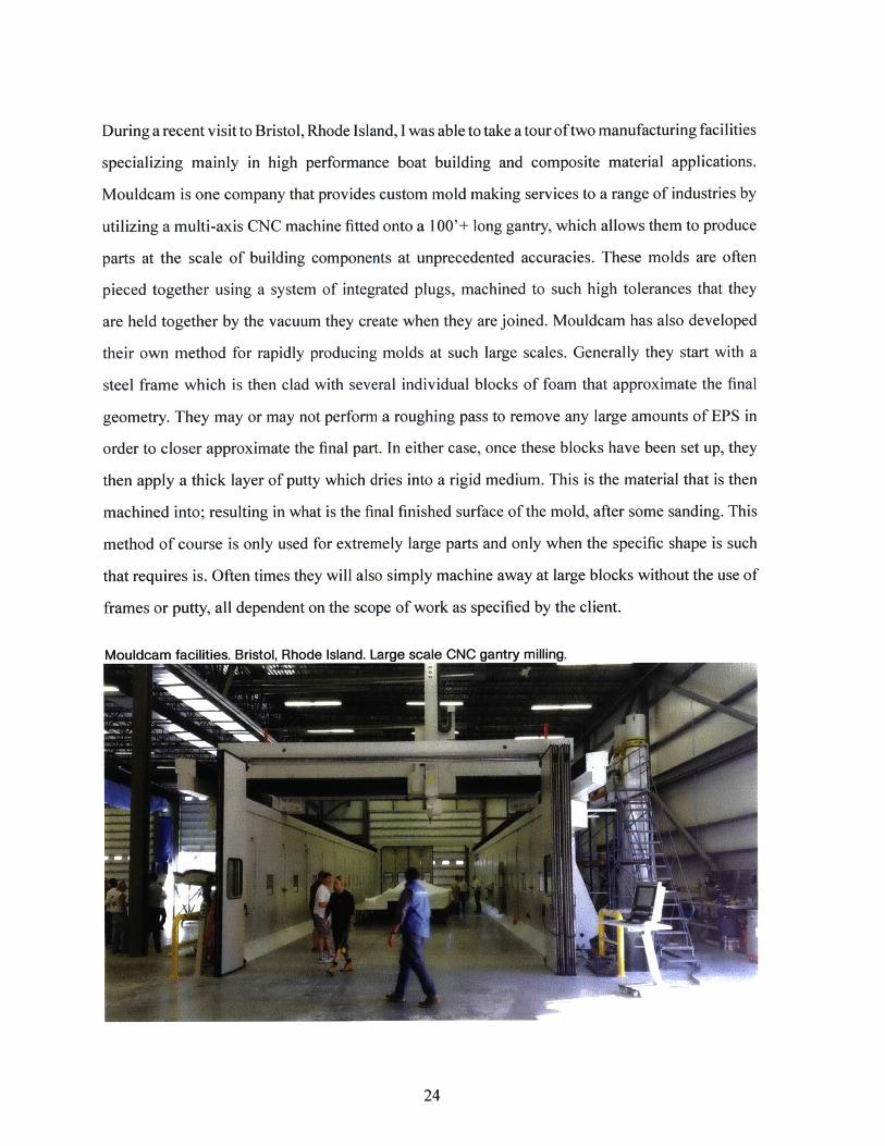
During a recent visit to Bristol, Rhode Island, I was able to take a tour of two manufacturing facilities
specializing mainly in high performance boat building and composite material applications.
Mouldcam is one company that provides custom mold making services to a range of industries by
utilizing a multi-axis CNC machine fitted onto a 100'+ long gantry, which allows them to produce
parts at the scale of building components at unprecedented accuracies. These molds are often
pieced together using a system of integrated plugs, machined to such high tolerances that they
are held together by the vacuum they create when they are joined. Mouldcam has also developed
their own method for rapidly producing molds at such large scales. Generally they start with a
steel frame which is then clad with several individual blocks of foam that approximate the final
geometry. They may or may not perform a roughing pass to remove any large amounts of EPS in
order to closer approximate the final part. In either case, once these blocks have been set up, they
then apply a thick layer of putty which dries into a rigid medium. This is the material that is then
machined into; resulting in what is the final finished surface of the mold, after some sanding. This
method of course is only used for extremely large parts and only when the specific shape is such
that requires is. Often times they will also simply machine away at large blocks without the use of
frames or putty, all dependent on the scope of work as specified by the client.
Mouldcam facilities. Bristol. Rhode Island. Large scale CNC
24

3.2 VACUUM BAGGING
Vacuum bagging is a commonly used process for producing composite parts against the surface
of a mold under pressure, and sometimes heat. Vacuum bags can be custom made to fit to size and
are often times reusable. The bags themselves are typically made of a high stretch nylon which is
capable of conforming into complex geometries with no webbing if accounted for properly. In this
case, the bags were made from a single sheet of nylon bagging film which were folded in half, and
taped shut on the remaining three edges using an extremely strong putty tape. The "middle edge"
was left to be sealed shut only after the mold and materials were placed inside. The tape is strong
enough to provide a completely airtight seal, while allowing the bagging film to still be pulled
apart from it cleanly in order to open the bag and remove the part.
There are two main types of vacuum bag curing processes when dealing with composites. One
is Vacuum Assisted Resin Transfer which relies on negative air pressure to not only suck down
the part to the mold, but to also slowly infuse the resin across the part automatically. This process
generally leads to more evenly infused parts, but can require a more complex setup than the second
process: wet lay-up. This process uses negative air pressure only to conform the part to the mold;
however the fibers themselves are infused with epoxy manually before it is placed inside the bag.
This process can sometimes be messier, but it also has its advantages when dealing with larger
parts or short time constraints. All of the prototypes made throughout the duration of this research
were made using the wet lay-up method.
with mold Dlaced inside Drior to first
25

The bag houses the mold and contains all of the layers of materials needed to produce a rigidized
surface. At the base is the mold itself, in this case machined EPS foam. Directly on top of the
foam is a layer of release film to protect the mold from any epoxy that might come into contact
with the finished surface. This is typically spray mounted down to prevent it from sliding and to
also conform to the mold more neatly. Next lies a layer of peel ply. Similar to a release fabric, the
peel ply is a finely woven nylon fabric often treated with a release agent that makes direct contact
with the part. Peel plies are available in different finishes and textures. I used a nylon release peel
ply to achieve a smooth yet somewhat gritty texture on the surface in order to better adhere to
the expanding urethane foam core. On top of the release film then lies the multiple layers of fiber
reinforcement, in this case burlap - a two directional woven cloth made of natural fibers. These
layers are sequentially infused by hand with a marine grade epoxy from U.S. Composites and laid
on top of one another inside the mold. On top of the final layer of fiber reinforcement rests another
layer of peel ply, then the breather layer, which is a perforated film meant to allow for excess resin
to flow through and into the bleeder layer. This is a thick layer of cotton cloth which absorbs any
excess resin. A small handful of this material is generally placed at the base of the vacuum line
where it meets the bag in order to prevent any excess resin from traveling into the vacuum.
26

Depending on the type of epoxy used, the curing process will vary in duration. All of the parts
produced throughout the course of this thesis were left to cure overnight anywhere between eight
to twelve hours. Typically in professional applications, especially when using pre-preg composite
fabrics, parts will be placed inside of a kiln during the curing process. This is done mainly due to
the use of thermoset resins, but also because of the additional strength provided by the applica-
tion of heat. Once a part has been set to cure in a vacuum bag overnight, the next step is to de-
mold. This process is relatively straight forward, yet it requires careful attention as the possibility
of puncturing the vacuum bag is at risk. Once the bag is opened, the mold is pulled out while all
of the layers are still tightly attached to it. Each layer is pulled away from the mold, beginning
with the outermost layer of bleeder and breather material and finally with the two layers of peel
ply attached to the part itself. In the best case scenario, the result is a rigidized yet somewhat
flexible part that has been thoroughly infused with epoxy in a balanced ratio of fiber to resin
matrix. These parts are then taken to a band saw and their borders are trimmed neatly, providing
a clean edge to work with.
27

Early prototypes. International Desin Center, MIT.
28

Early prototypes. International Desin Center, MIT.
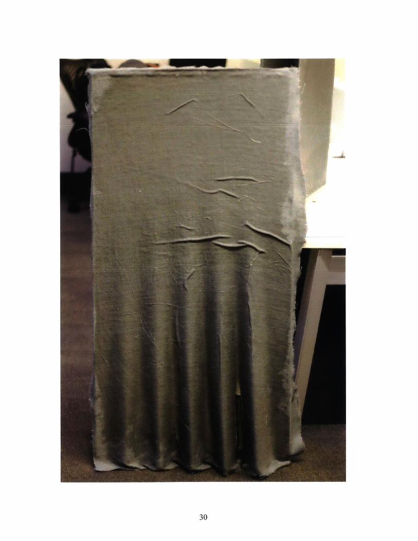
29
I
C0

Early prototypes. International Desin Center, MIT.
31
I
3.3 BACKFILLING / INFILLING
Perhaps the most important process involved with the construction of variable thickness sand-
wich structures is the act of backfilling or infilling the core between the two skins. Backfilling
and infilling are two methods used to describe the process of joining an inner and outer skin,
creating what becomes the poche of the sandwich. This process uses rigid closed cell expanding
polyurethane foam which is poured in between the two skins.
Expanding urethane foam is widely used in a number of applications ranging from architectural
insulation to decoration to acoustic applications. Originally developed by the military in the
1940's for use in airplanes it later became used as an insulation material through a spray on ap-
plication. Today it is commercially available and also widely used in the production of props and
large composite sculptures. It varies in density and expansion rate and is generally manufactured
as a two part mixture. The foam used in the prototypes here has a density of 3 lbs. per cubic foot
and an expansion rate of 1:18 by volume.
Conceptually, the process of infilling between two surfaces is different than simply casting a
distinct volumetric element even though both may result in a single 3-dimensional object. One
can perceive infill as a strategy for implementing solid mass in areas where it's necessary for a
variety of reasons, be it structural, architectural, functional, etc. The purpose of using infill here
is mainly to allow for variable thickness within laminar assemblies. For instance, in areas where
two surfaces are pressed together to form a single surface, the space between them becomes
increasingly smaller. It is in these tight areas in particular where an expanding medium such as
urethane proves to be advantageous, resulting in maximum contact between the two skins in all
possible moments.
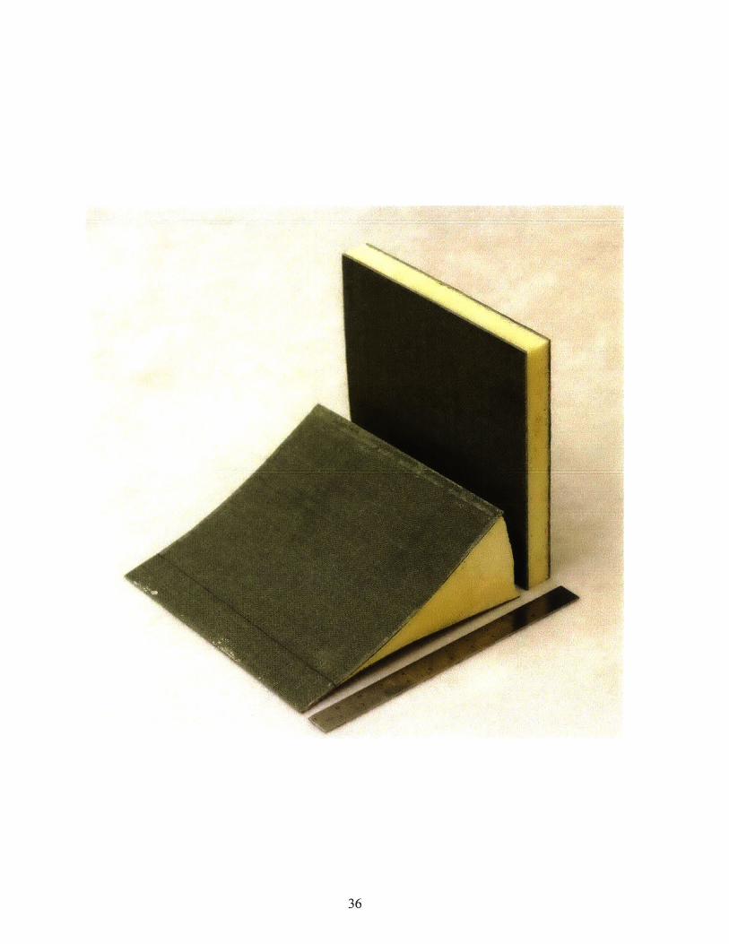
Technically, the process of infill is carried out in a relatively simple method. First, the two skins
are trimmed down to the same perimeter on both parts. This allows them to be held in place to-
gether by a number of other pieces, typically a sheet material like acrylic or aluminum. As shown
in the figure below the two skins are each adhered to pieces of aluminum and acrylic using hot
glue and are separated by a space in between. The foam is then mixed and poured in from a hole
on top. It expands rapidly, and is ready to be de-molded after about an hour. The result is a rigid,
lightweight assembly composed of two skins and a cellular solid core in between.
32

Early infill sequence. International Desin Center, MIT.
33

Early infill sequence. International Desin Center, MIT
34

Early infill sequence. International Desin Center, MIT.
35
36

37
.... ......

Standard thickness composite sandwich.
Variable thickness composite sandwich.
38

It is important to note that foam tends to expand in a particular manner; first horizontally until it
either reaches its limits or a physical boundary, then vertically. This information is useful when
considering the physical orientation of a part in space and how to best accommodate for core
expansion. Also, because expanding urethane is exothermic, it's best to pour multiple times in
smaller amounts in order to minimize heat from off gassing. While this may seem as a burden at
first, in actuality it has many benefits. For instance, it's possible to vary the density of the core
simply by controlling the number and location of pours between the two skins. Also, by varying
the density of the foam itself within the core, one can apply higher density foams closest to the
skins where more strength is required and lower density foam towards the center where less
weight is desired. Due to the adhesive properties of urethane foam, performing multiple pours
will ensure the material will always bond to itself.
ii0
Early standard thickness prototype sections.
39
S 7
-~
+
0'I,
0)
A A>
I A /\
A A A A A A
II
I8
II,.1 I

4.0 Results
41

4.0 Results
Overall, the process of constructing variable thickness sandwich structures proved to be fairly
tedious, labor intensive, time consuming, full of unknowns, yet rich with potential. Given this
work is in its earliest stages of development at this time, the process is still being invented. Variable
thickness, by nature implies non-standard logics and customized methods as opposed to standard,
commercially available composite sandwich panels which are generally flat and parallel. What this
process does produce however, is an incredible rigid part with the ability to perform differently on
either side of the structure. For instance, the use of corrugation on one surface can provide both
acoustical and structural properties simply from its shape, while the opposing skin can provide
a flat surface for walking or working on. This allows us the ability to think more freely about
internal and external functions, and to be able to shape their spatial qualities independently from
one another, similarly to the 9 cathedrals drawn though figure-ground.
The process of laminating several layers of burlap infused with epoxy proved to yield surfaces of
complex geometries with relatively high fidelity to their digital counterparts. While burlap was
used as an inexpensive and natural analog to carbon, it still demonstrated that it could provide a
strong enough surface to produce a sandwich structure capable of withstanding at least the weight
of a human being. It's no question that carbon is superior to burlap in terms of strength however it
also much more expensive. Burlap was also chosen for its aesthetic qualities over carbon as well,
further demonstrated by the use of a carbon layer sandwiched between two sheets of burlap to hide
its presence yet benefit from its structural capabilities. This was done in only one prototype.
42
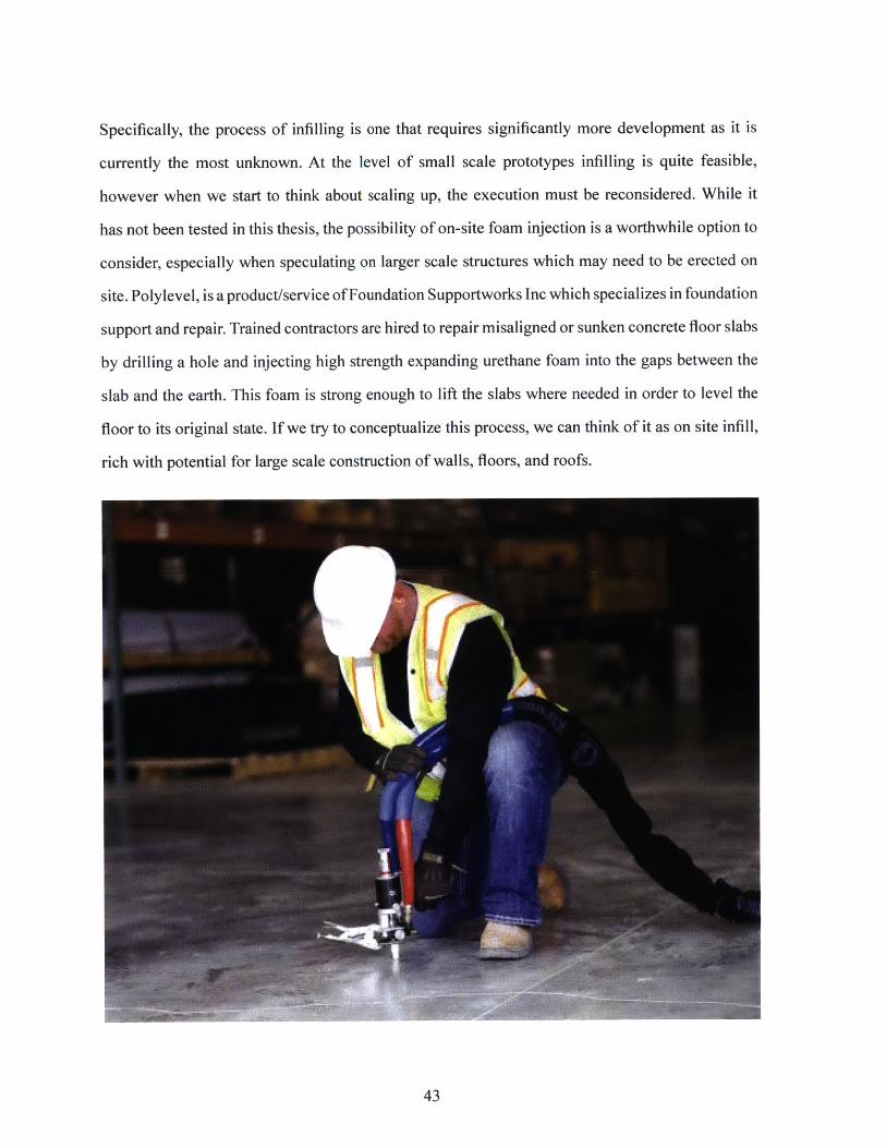
Specifically, the process of infilling is one that requires significantly more development as it is
currently the most unknown. At the level of small scale prototypes infilling is quite feasible,
however when we start to think about scaling up, the execution must be reconsidered. While it
has not been tested in this thesis, the possibility of on-site foam injection is a worthwhile option to
consider, especially when speculating on larger scale structures which may need to be erected on
site. Polylevel, is a product/service of Foundation Supportworks Inc which specializes in foundation
support and repair. Trained contractors are hired to repair misaligned or sunken concrete floor slabs
by drilling a hole and injecting high strength expanding urethane foam into the gaps between the
slab and the earth. This foam is strong enough to lift the slabs where needed in order to level the
floor to its original state. If we try to conceptualize this process, we can think of it as on site infill,
rich with potential for large scale construction of walls, floors, and roofs.
43

5.0 Speculations & Projections
44

5.0 Speculations & Projections
5.1 SMALL SCALE TESTING
This thesis aimed to develop a series of methodologies ranging from design logics via computational
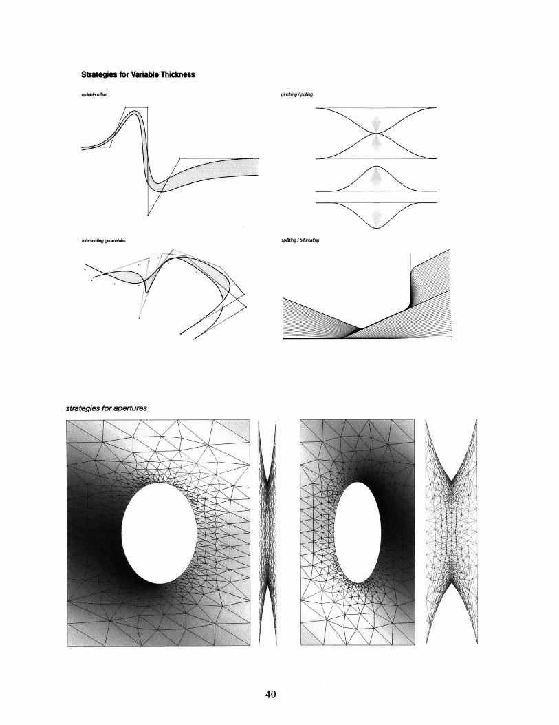
and parametric modeling to physical and material testing via small scale prototypes. Using strategies
such as adaptive corrugation, variable offsetting, pinching, and pulling to create various conditions
responding to certain demands, I was able to develop a sense of understanding on how certain
design moves would behave physically. For instance a surface which transitioned from a corrugated
section to a flat section showed most structural integrity in moments of depth as opposed to flatness.
Or perhaps a more nuanced example, where by testing the number of laminations within a single
burlap assembly I was able to discern a range of stiffness to translucency and how the porosity of
a single surface affected the amount of urethane foam that might seep through during expansion.
These and other characteristics of specific material behaviors often times were only made apparent
through hands on experimentation. The relationship between hands on material experimentation
and design speculation is one that I feel must be reciprocal, continuous, and informative through
exchange.
45

5.2 ARCHITECTURAL PROPOSITIONS
Utilizing these experiments and reciprocal relationships, this thesis explored two small design
proposals as a means of testing architectural intentions with previously developed design and
construction methods. The first proposal, a public seating canopy stationed at a rest area, aimed
to explore variable thickness in section by transforming between moments of extreme thickness
to extreme thinness. The second proposal, a more intimate canopy aimed to explore this same
variation not only in section, but also in plan as well as in terms of its program.
Proposal 1 embodied strategies of adaptive corrugation and bifurcation by demonstrating two
main features visible in any given section of the structure. One is the moment of transition between
thick and thin, evidenced by the change in profile from seating to overhang, and the other - is the
moment where once two surfaces merge to become one, they now rely on shaping rather than
thickness to perform structurally. This is seen by the crenulation in the areas of overhang.
In both plan and section, this scheme is clearly symmetrical. This is the result of an effort to minimize
the number of unique elements within the structure and reduce the amount of molds, labor, and
time required to construct it. This is also simply a first attempt at jumping to an architectural scale
with the given system and therefore proceeded with more caution than perhaps should be. Non-
standard material deployment meets standardized symmetrical construction types - potentially a
less interesting design scheme however perhaps more economic.
46
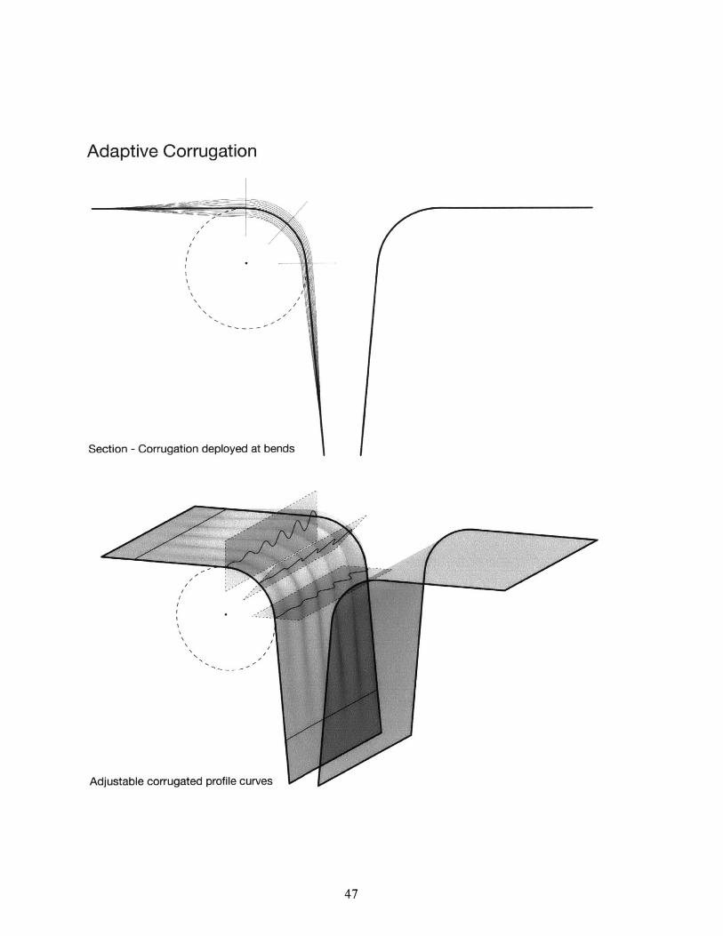
Adaptive Corrugation
Section - Corrugation deployed at bends
Adjustable corrugated profile curves
47

Rigidized compositeskin at corrugatedregion.
Rigidized composite00sk In at flat region to
accommodate forsitting.
e.Expandableurethane foam core.
VA~<'W
Proposal 1 - Sectional Perspective
48
IfVqd

Proposal 1 - Section
49

Proposal 1 - Elevation
Proposal 1 - Plan
50

51

52

53
Proposal 2 focused on creating three distinct moments of section, each of which vary in function
as well as in thickness, however all three moments are joined through a singular structure which
creates both an outdoor area and a more enclosed space simultaneously. In plan, the structure
transforms from a bench, which wraps around and becomes a thin translucent screen and gradually
thickens to create an enclosure with integrated seating on the inside, providing a small and intimate
space for dining. Much like Proposal 1, Proposal 2 also deploys structural crenulation on the
interior surface of the enclosure where is becomes much thinner in section in order to reduce
weight, while still maintaining a relatively smooth surface on the exterior. While not intended to
perform under the same conditions, this is a technique that is commonly used in the construction
of high performance racing boats, where the exterior requires smoothness in order to cut through
hydrostatic forces while the interior is crenulated to provide structural stability.
One thing that is very clear about this scheme unlike Proposal 1 is that is has no standardized or
repeated geometries, and therefore requires a greater number of unique molds in order to produce
all of the surface area. Naturally this could increase the cost of manufacturing along with the
amount of time needed for construction.
54

Proposal 2 - Perspective
Proposal 2 - Section
55
a
L...........

Proposal 2 - Plan
Proposal 2 - Elevation
56
5.3 FUTURE RESEARCH
Although this research has touched on a number of issues surrounding the design and development
of variable thickness sandwich structures, there is much to be learned from future explorations.
There are a wide range of variables to be explored, from the range of textiles, resins, foams,
lamination methods, mold making techniques, infill strategies, joining techniques, and shaping
logics to highlight a few. In addition to these topics, this research may benefit greatly from feedback
received from closely monitored structural testing. Currently there have been no structural load
tests performed to test the capacity of these systems. Although that is not the focus of this research,
it may still prove to be beneficial especially when taking on architectural proposals more seriously.
It would also be necessary to expand the authorship of this work into a diverse group of expertise
which may take on the form of collaborations across industries. Much of these methods are standard
practice to many professionals in the boat building industry, who have a wealth of knowledge to
share regarding composite construction. As the scope of contemporary architectural practice and
pedagogy expands into other design fields and disciplines, it is critical to develop a mindset that
allows for productive collaborations which blur disciplinary boundaries. Of course, this is already
happening in some regards, yet it is still only the exception and far from the norm. One current
notable example of this type of collaborative, cross disciplinary effort is architect Greg Lynn, who
has recently completed the design and construction of GF42 - a 42' long yacht - in collaboration
with Westerly Marine, Krysler & Associates, Courouble Design & Enginering, a structural
engineer, two computational fluid dynamics engineers, and a rig designer amongst others. In order
to successfully adopt skills and expertise from another discipline - in this case naval design and
engineering - the architect must seem to act as a liaison between several specialized experts from
a broad range of backgrounds. Much in the same way these collaborations take place, I speculate
that similar efforts could be taken on to further develop the methods and results covered in this
thesis.
57

6.0 Bibliography
1. Clifford, B and McGee, W 2011, 'Matter and Making: Periscope Foam Tower' in Glynn, R
and Sheil, B (eds), Fabricate: Making Digital Architecture, Riverside Architectural Press, Lon-
don pp. 76-79.
2. Carpo, M 2011, The Alphabet and the Algorithm (Writing Architecture), The MIT Press, Cam-
bridge, MA.
3. Pye, D 1968 The Nature and Art of Workmanship, Cambridge University Press, London.
4. Gibson, L 1988 Cellular Solids; Structure & Properties, Pergamon Press
5. Akovali, G. 2001 Handbook of Composite Fabrication, Rapra Technology Limited, Shawbury
UK
6. Schropfer, T. 2011 Material Design; Informing Architecture by Materiality, Basel: Birkhauser
7. Fernandez, J. 2006 Material Architecture; Emergent materials for innovative buildings and
ecological construction. Architectural Press, Oxford.
8. Banham, R. 1967 Thoery and Design in the First Machine Age, Frederick A. Praeger, Inc.
Publishers, New York, NY.
9. May, J and Koreitem, Z. 2014 New Massings for New Masses; Collectivity After Orthography,
MIT Keller Gallery and MIT Architecture (Exhibition Text)
10. Davidson, C. 2014 Log 31, New Ancients. Published by Anyone Corporation, New York, NY.
11. Lefteri, Chris. Making It: Manufacturing Techniques for Product Design. 2nd ed. London:
Laurence King Pub, 2012.
12. Frichot, Helene, and Stephen Loo. Deleuze and Architecture. Edinburgh: Edinburgh Univer-
sity Press, 2013.
58

13. Spuybroek, L. 2011. The Sympathy of Things: Ruskin and the
Ecology of Design, V2 Publishing, Rotterdam.
14. Rippmann, M and Block, P 2011, 'Digital Stereotomy: Voussoir geometry for freeform
masonry-like vaults informed by structural and fabrication constraints' Proceedings of the IAB-
SE-IASS Symposium 2011, London, UK.
15. Pronk, A, Rooy, I and Schinkel, P. 2009. "Double-curved surfaces using a membrane mould"
Proceedings of the International Association for Shell andSpatial Structures (IASS) Symposium
2009, Valencia, Spain.
16. Fallacara, G. 2006. "Digital Stereotomy and Topological Transformations: Reasoning about
Shape Building" Proceedings of the Second International Congress on Construction History, Vol.
1, pp. 1075-1092.
17. Fallacara, G. 2006. "Digital Stereotomy and Topological Transformations: Reasoning aboutShape Building" Proceedings of the Second International Congress on Construction History, Vol.1, pp. 1075-1092.
18. Pigram, D and McGee, W. 2011. "Formation Embedded Design: A methodology for theintegration of fabrication constraints into architectural design", ACADIA 11: Integration throughComputation [Proceedings of the 31st Annual Conference of the Association for Computer AidedDesign in Architecture, 13(16), pp. 122-131.
19. Raun, C, Kristensen, M and Kirkegaard, P. 2010. "Flexible Mould for Precast ConcreteElements" Proceedings of the International Association for Shell and Spatial Structures (IASS)Symposium 2010, Shanghai, China.
20. Ekmekjian, Nazareth. 2014. "From Surface to Volume: An Approach to Poche' with Com-posites", ACADIA 14: Design Agency [Proceedings of the 34th Annual Conference of theAssociation for Computer Aided Design in Architecture (ACADIA) ISBN 9781926724478]LosAngeles 23-25 October, 2014), pp. 573-578
21. Clifford, B. and Ekmekjian, N. and Manto, A. and Little, P. 2014. "Variable Carving VolumeCasting; A Method for Mass-Customized Mold Making" Robotic Fabrication in Architecture,Art, and Design. Proceeding of RobArch 2014 Conference, University of Michigan, 2014 pp.3-15.
59

ARCHITECTURE SANDWICHEDTuning anisotropy through variable thickness and hetereogeneous laminar assemblies.
Thesis Committee:
Thesis AdvisorBrandon CliffordBeluschi Lecturer, Department of Architecture, MIT
Thesis AdvisorMark GoulthorpeAssociate Professor, Department of Architecture, MIT
Thesis ReaderNader TehraniProfessor, Department of Architecture, MIT
60

61


