CHAPTER 2 TECHNOLOGICAL PROCESSES
26
SC Unitatea de Suport pentru Integrare SRL, www.studiidemediu.ro RSEIM+EA Capitolul 2 SNTGN Transgaz SA, Mediaș Dezvoltarea pe teritoriul României a Sistemului Național de Transport Gaze Naturale pe coridorul Bulgaria-România-Ungaria-Austria 87 | Pag. din 3 CHAPTER 2 TECHNOLOGICAL PROCESSES Technological processes are defined as representing the sum of mechanical, physical, chemical (if the case) operations that are carried out simultaneously or in a sequential manner in order to transform raw materials into goods or to assembly, repair and maintain technical systems. The categories of equipment involved, according to the types of processes, are as such: manual, mechanized, automated or mixed; taking into account the purpose aimed at, the technological processes could be: for dismantling, destruction, construction, testing, maintenance, measurement, assembly, transportation, etc .; in accordance to the procedure occurring in the course of operations, the following technological processes distinguish: mechanical, thermal, electrical, chemical, electrochemical, thermo-chemical, bio-chemical, etc. In the environmental assessment, the processes to be addressed in project implementation must be clearly defined in order to perform a proper analysis in the most comprehensive manner, focusing on each of the stage of construction enabling to accurately assess the ecological footprint of the project. Knowing these details an objective prediction on the potential impact of the project as a whole can be issued and therefore a proper set of mitigation solutions can be proposed. 2.1. Technological processes of production BRUA project consists mostly of construction processes (construction and assembly). 2.1.1. Describing the proposed technological processes Summary flowchart of processes to be carried out to build BRUA consist of: - acquiring right of way to target land This stage involves carrying out of administrative procedures, including identification of landowners affected by BRUA pipeline construction and negotiating with owners / managers of lands targeted, so as to clearly establish the conditions for access and the conducting of works. - Access to work fronts by making temporary ways (technological); Using existing road networks, a brief systematization and (where necessary) improvement will be assumed in order to ensure access to working areas. Where such access routes cannot be identified, temporary access routes to the working areas will be temporarily created. - Site organization and ensuring the appropriate technical and urban amenities: Along BRUA five site organizations were defined, to be located in close proximity to roads (DN, DJ, DC), so as to efficiently solve logistic issues. Within these perimeters in the area of about 10.000sqm temporary structures (containers) and storage shelters for equipment, machinery and materials (pipes, sand, etc.) will be installed. - Delineation of working areas, providing temporary protection regimes and their corresponding signaling; Transposition in site of demarcations corresponding to the fronts of work, the site organization and technological perimeters will be achieved by field measurement (metal poles painted in contrasting colors, with warning inscriptions) demarcation with plastic strips (nylon) and signaling by means of informative
Transcript of CHAPTER 2 TECHNOLOGICAL PROCESSES

SC Unitatea de Suport pentru Integrare SRL, www.studiidemediu.ro
RSEIM+EA Capitolul 2
SNTGN Transgaz SA, Mediaș Dezvoltarea pe teritoriul României a Sistemului Național de Transport Gaze Naturale pe coridorul Bulgaria-România-Ungaria-Austria
87 | P a g . d i n 3
CHAPTER 2 TECHNOLOGICAL PROCESSES Technological processes are defined as representing the sum of mechanical, physical, chemical (if the case) operations that are carried out simultaneously or in a sequential manner in order to transform raw materials into goods or to assembly, repair and maintain technical systems. The categories of equipment involved, according to the types of processes, are as such: manual, mechanized, automated or mixed; taking into account the purpose aimed at, the technological processes could be: for dismantling, destruction, construction, testing, maintenance, measurement, assembly, transportation, etc .; in accordance to the procedure occurring in the course of operations, the following technological processes distinguish: mechanical, thermal, electrical, chemical, electrochemical, thermo-chemical, bio-chemical, etc. In the environmental assessment, the processes to be addressed in project implementation must be clearly defined in order to perform a proper analysis in the most comprehensive manner, focusing on each of the stage of construction enabling to accurately assess the ecological footprint of the project. Knowing these details an objective prediction on the potential impact of the project as a whole can be issued and therefore a proper set of mitigation solutions can be proposed. 2.1. Technological processes of production BRUA project consists mostly of construction processes (construction and assembly). 2.1.1. Describing the proposed technological processes
Summary flowchart of processes to be carried out to build BRUA consist of: - acquiring right of way to target land
This stage involves carrying out of administrative procedures, including identification of landowners affected by BRUA pipeline construction and negotiating with owners / managers of lands targeted, so as to clearly establish the conditions for access and the conducting of works.
- Access to work fronts by making temporary ways (technological); Using existing road networks, a brief systematization and (where necessary) improvement will be assumed in order to ensure access to working areas. Where such access routes cannot be identified, temporary access routes to the working areas will be temporarily created.
- Site organization and ensuring the appropriate technical and urban amenities: Along BRUA five site organizations were defined, to be located in close proximity to roads (DN, DJ, DC), so as to efficiently solve logistic issues. Within these perimeters in the area of about 10.000sqm temporary structures (containers) and storage shelters for equipment, machinery and materials (pipes, sand, etc.) will be installed.
- Delineation of working areas, providing temporary protection regimes and their corresponding signaling; Transposition in site of demarcations corresponding to the fronts of work, the site organization and technological perimeters will be achieved by field measurement (metal poles painted in contrasting colors, with warning inscriptions) demarcation with plastic strips (nylon) and signaling by means of informative

SC Unitatea de Suport pentru Integrare SRL, www.studiidemediu.ro
RSEIM+EA Capitolul 2
SNTGN Transgaz SA, Mediaș Dezvoltarea pe teritoriul României a Sistemului Național de Transport Gaze Naturale pe coridorul Bulgaria-România-Ungaria-Austria
88 | P a g . d i n 3
panels; points with higher levels of risk shall be signaled accordingly, limiting the access as stated by legal provisions and technical security standards.
- Area clearance within the working area; Within the targeted perimeter a brief inventory of pre-existing elements (temporary/artificial structures, fencing etc.) will be carried out, and proper solutions (relocation, financial compensation, etc.) will be adopted in order to clear the way for the works and to avoid all litigation with owners / managers of land.
- Removal of vegetal cover, including deforestation works where necessary; Depending on the structure of the vegetation, removal actions (mowing, clearance deforestation, etc.) will be initiated. Herbaceous vegetation will be mowed, dried and stored in haystacks and vegetation shrubs and woody plants will be grinded and the resulting material will be stored temporarily in the immediate proximity in stacks of compost (mixed with topsoil or deep-soil). When works are finalized, the organic material will be used in order to recover the topsoil level, accelerating the process of ecological restoration.
- Stripping topsoil layer (on about 30 cm); Topsoil will be stripped and bulldozed on a depth of up to 30 cm. Topsoil will be deposited into stacks located on one edge of the site, and will be used in order to recover the topsoil level after the finalization of works.
- Excavation of the trench for the transmission pipeline laying; On the median strip, a trench will be excavated of: 2,2m on the surface and 1.4m at the bottom of the trench and 1.9m deep. The excavated soil will be deposited in close proximity of the excavated trench.
- Making the sand bed; On the bottom of the excavated trench a bed of sand or sifted soil will be laid of 12 cm thick for the laying of the pipeline;
- Pipeline assembly (stringing pipe sections along the trench, their welding, welding testing and leak testing of the pipeline sections, applying insulating sleeves, etc.); The pipeline sections will be welded together, after being laid in the excavated trench. Welds between pipeline sections will be visually tested. After testing the welded areas the heat shrink sleeves will be applied to protect exposed surfaces of pipes.
- Laying the pipeline in the trench; Following the completion of continuous sections of pipeline, they will be laid progressively in the trench using specialized tools (pipeline launchers). After laying, the welds between sections will be tested by specific methods (ultrasonometry and pressure tests, etc.).
- Construction of additional supporting elements (if applicable); In some points that require increased supporting (abutments, bank protection, etc.), additional construction works will be envisaged.
- Cover of the trench, leveling and backfilling of excavated perimeters; After the pipeline laying works, sand will be added to the sand bed and the trench will be filled with excavated soil. The process of filling the trench will be carried out in successive compacted layers; the surplus of excavated soil from the trench will be used for backfilling of the entire working strip.
- Cleaning and testing of pipelines: After installing the pipelines in the trench, the pipeline sections will be cleaned, pneumatic (air) resistance will be carried out for pipeline sections of location classes 1a, 1b and 2 and hydraulic resistance (water) for the pipeline sections of 3 and 4 location classes, followed by pneumatic (air) testing for all location classes.
- Completion of pipeline sections and reinforcement installation: After conducting pressure tests, valves stations are mounted for the commissioning of the pipeline.
- Disposal of the machinery, equipment and working tools at the site;

SC Unitatea de Suport pentru Integrare SRL, www.studiidemediu.ro
RSEIM+EA Capitolul 2
SNTGN Transgaz SA, Mediaș Dezvoltarea pe teritoriul României a Sistemului Național de Transport Gaze Naturale pe coridorul Bulgaria-România-Ungaria-Austria
89 | P a g . d i n 3
Machinery and equipment will be removed from the site, and the temporary storage areas will be closely monitored to reveal any traces of associated impacts (compaction, oil stains, etc.). All areas that keep traces of impact categories will be defined and subject to certain in line processes.
- Reinstatement of sites to their initial state and ecological reconstruction of the impacted perimeters; After the site morphological reconstruction, the topsoil will be laid as well as the plant debris (debris sites) supporting germination of initial phases. Seeding, overseeding and re-planting of woody plants, if the case. Items temporarily relocated or removed will be replaced or rebuilt on site.
- The installation of structures requested for BRUA (gas compressor stations, valve stations, etc.); Structures will be constructed, including gas compressor stations, valve stations, cathodic protection stations, etc
- Construction of structures to mitigate the environmental impact; In order to reduce the BRUA associated impact, further works will be carried out consisting in ecological reconstruction works for the affected perimeters and the proximity areas in order to guarantee long-term preservation of the integrity of the environment (especially land). Such works consist of: re-vegetation, planting of shrubs and woody plants, installation of microstructures (microhabitats) of natural materials (rocks, piles of dead branches, etc.) or artificial (shelter houses, feeders, etc. all in order to accelerate colonization, growth indices of biodiversity and thus to regain a stable balance of ecological communities affected.
- Delineation and marking the perimeters of risk and technological protection; This will involve installation of a network of ground terminals, warning panels and demarcation of risks perimeters, including technological protection perimeters.
- Post implementation and post-operation monitoring programme (a period of about 36 months); Subsequent to BRUA construction completion, a monitoring program will be ensured in order to monitor the environmental recovery status complying to regulatory issued documents.
- Assuming (if the case) of remedies; Where elements insufficiently treated will be identified within the affected perimeters, a set of recovery actions will be proposed, to be undertaken by the beneficiary of the project.
- Continuing (if applicable) of the monitoring program and evaluation (validation) of mitigation measures undertaken. If necessary, a monitoring program will be implemented in order to validate the mitigation actions.
2.1.2. Details on the necessary techniques and equipment 2.1.2.1. Strategic approach In terms of the strategic approach for BRUA construction and given the dimension of the project (about 528 km) a route division was considered and works sectors were defined. 5 sectors were defined, each sector covering approximately 100 km of the pipeline route. One site organization will be placed for each sector (at halfway distance). Works on 4 distinct work fronts will be assigned for each site organization, each having the responsibility to construct a pipeline section between 10 and 40 km, depending on the complexity of the route, soil structure, etc. Such an approach allows accurate tracking of the project implementation and efficient management of resources, equipment and raw materials. The supplementation of the working capacities is considered for the work fronts that will have difficulties in running the activities; thus the possibility of balancing, dosing and equilibrating human effort, material flow and technological support, so the whole calendar of works to be observed. 2.1.2.2. Equipment There will be one working team for each working front, whose personnel and technological equipment complies with the regulations for such projects. The list of equipment to be used by a working team includes:
- 4 pipeline launchers, each of 20 t; - One average bulldozer (22t); - One smaller bulldozer (12t);

SC Unitatea de Suport pentru Integrare SRL, www.studiidemediu.ro
RSEIM+EA Capitolul 2
SNTGN Transgaz SA, Mediaș Dezvoltarea pe teritoriul României a Sistemului Național de Transport Gaze Naturale pe coridorul Bulgaria-România-Ungaria-Austria
90 | P a g . d i n 3
- 1 medium 20t excavator; - Tank vehicle (or trailer towed) for water; - 4 trucks (4 axes); - One rotary excavator with buckets ER7 of 37t; - One tractor with trailer; - 1 backhoe loader; - Six welding inverters; - 1 welding aggregate; - 4 turbine pumps; - 2 turbo compressors; - 1 mobile storage container; - a dressing room trailer equipped with first aid point; - an office trailer; - 1 electricity generating aggregate (electric generator);
Each team will be equipped with hand tools (shovels, spades, hand tools, etc.) and each worker will wear specific protection equipment. Where appropriate, the list of equipment will be completed (by specific contracts) with:
- Crane; - Concrete pump; - Specialized vehicles prepared for the concrete transport; - Loaders, etc.
Pipeline sections will be transported by trucks with 12-14m platforms. One mobile toilet, with sealed and chemically treated basin will be placed within working areas 2.1.2.3. Techniques used The techniques used will comply with specific technological schemes, to be detailed in optimized implementation projects which will be subject to procedures undertaken by a third company to be entrusted with this responsibility. The construction of BRUA will usually entail common construction techniques, such as deforestation (if applicable), summary preparation of sites (bulldozing), excavation, construction and installation of the pipeline, and of GCSs, valves stations, etc. The document hereinafter describes some of the specific elements of the project such as:
A. Transportation of pipe sections For the construction of BRUA steel pipe sections each of 12-14m length, and outer diameter of 813mm (32) will be used. Pipe sections may be purchased from import. Transportation of the pipe sections will be by train or at sea depending on the source of supply and transport opportunities. From the railway stations, transport will be by trucks with trailers; there is no need for special oversized transport.
B. Excavation Excavation will be carried out in accordance with NT118 / 2013 provisions as per the requirements:
- for land in lowland and hilly areas with no coarse material (large stones), the bulldozed topsoil will be placed in temporary storage areas to be used for backfilling;
- for land sites in mountain areas (or where the soil is mixed with coarse material: large stones, stony ground) the bulldozed topsoil will be placed in temporary storage areas to be used for backfilling; the soil with coarse material and the soil excavated from the trench will be shredded using a mobile crushing station. After the completion of works the shredded soil will be used for backfilling and the topsoil will be placed in the upper level;

SC Unitatea de Suport pentru Integrare SRL, www.studiidemediu.ro
RSEIM+EA Capitolul 2
SNTGN Transgaz SA, Mediaș Dezvoltarea pe teritoriul României a Sistemului Național de Transport Gaze Naturale pe coridorul Bulgaria-România-Ungaria-Austria
91 | P a g . d i n 3
Excavation works will be mostly mechanized. Besides the usual usage of excavators (Castor type) of medium size and in sensitive areas (forests and areas with excess moisture, in proximity of urban areas) smaller capacity excavators and backhoe loaders will be used. During this stage, trench excavation can be performed using a rotary excavator with buckets (see fig.2.I.) ensuring significant work yields and ensuring a high speed forwarding of fronts, thus reducing the duration of works. The use of such equipment has the advantage of achieving a net delimited ditch with stabilized walls without damaging proximal soil layers; excavated soil is crushed, making it easier to use when plugging trench, allowing compaction in a shorter period of time and with reduced mobilization of equipment and machinery. In this case, filling the trench with an average capacity backhoe can be carried out.
Fig.2.I. Model excavator bucket rotation
Thus, even if operating costs are higher (transport, on-site operation by specialized teams, etc.) and the impact on the environment is reduced, this solution represents a more attractive technology related to project implementation. For excavation in inaccessible areas there in order to minimize environmental impact and creating a confined, restricted strip, spider excavators (see fig.2.II) will be used. With these types of equipment the entire preparative works, and excavation can be completed. In sensitive places (intersection of pipeline or in close proximity to them), digging will be carried out manually. The excavation will be performed so that the pipeline can be positioned below the frost limit, ensuring a minimum distance of 1m from the ground surface and the upper limit of the pipe.
Fig.2.II. Model spider excavator
C. Embankments Some sections of BRUA will require additional earthworks, especially in areas where the pipeline route is on the level curve, and where land is less stable. Earthworks will consist of trench excavation and by creation of a geometrical structure in order to comply to stability angles of the slopes. Excavated material in excess will be used locally as backfilling material to be deposited in depressions, etc.
D. Horizontal drillings In order to reduce environmental impact (especially when crossing major water courses), but also to avoid damage of major transport and communications infrastructure (railway, roads, etc.), the horizontal drilling solution was chosen. Horizontal drilling is performed using specialized equipments. Drillings are performed from both ends (see fig.2.III).

SC Unitatea de Suport pentru Integrare SRL, www.studiidemediu.ro
RSEIM+EA Capitolul 2
SNTGN Transgaz SA, Mediaș Dezvoltarea pe teritoriul României a Sistemului Național de Transport Gaze Naturale pe coridorul Bulgaria-România-Ungaria-Austria
92 | P a g . d i n 3
Fig.2.III. Scheme realization of horizontal directed drilling
E. Welding joints
Pipe sections will be laid along the trench after being transported to the site from the pipe deposits, by trucks (see fig.2.IV). Sections will be inspected, and particularly tested for the protective insulation structure (see fig.2.V). Where necessary, insulation will be restored; in case of significant damage, pipe segments will be replaced. Welding joints will be performed in accordance with procedure SREN ISO15607. The quality control process for welded pipes will be carried out using gammagraphy method with a very low the radiation level, falling within limits, and therefore not requiring supplementary protective measures. After certifying compliance of welding works, the process will continue with the insulation phase, applying heat shrinkable sleeves. Heating will be done using butane open-flames lamps. Cracks will be marked and corrective action will be made in order to restore welds. Completed sections are then welded together by carefully performed welding works and further checked by gammagraphy.
Fig.2.IV. Pipeline segments spread along
the construction lane
Fig.2.V. Verification of the insulation of
pipelines F. Launching of pipe sections

SC Unitatea de Suport pentru Integrare SRL, www.studiidemediu.ro
RSEIM+EA Capitolul 2
SNTGN Transgaz SA, Mediaș Dezvoltarea pe teritoriul României a Sistemului Național de Transport Gaze Naturale pe coridorul Bulgaria-România-Ungaria-Austria
93 | P a g . d i n 3
Pipe sections will be launched in the excavated trench that has been paved with sand (thickness of 12 cm) which will ensure a proper alignment (see fig.2.VI). Pipeline launchers are specialized equipment, usually using the chassis of bulldozers, which are provided on one side with a jib and a counterweight on the opposite side. Sections of pipeline are launched by elastic beam pipe, and the number of launchers is established according to the pipe segment diameter and length. This launching procedure starts at one end of the pipeline and advances towards the other end, gradually, on one section of the pipeline at a time. Once reaching the bottom of the trench, the backward machine moves towards the top of the row.
Fig.2.VI. Column of pipe launchers in the
trench
The operation is repeated gradually until whole section is released. One end is left out of the trench, preparing the welding of further consecutive sections. Pneumatic and hydraulic tests of strength After launching the pipeline and ground cover it, go to achieve technological tests on sections of 5 km.
G. Resistance tests: This step can be done either by means of pneumatic, or hydraulic method. The resistance test using water was used for pipeline sections mounted in location class 3; for sections of pipeline in location classes 1a, 1b and 2 the resistance test is made using air (pneumatic method); the water is pumped from close proximity of the location from streams. The water is transported at site by tank-trucks provided with filters, thereby avoiding the introduction of silt, mud or other contaminants inside the pipelines. Water is introduced into test sections through special connector devices. Technological tests are carried out by pumping water into the pipelines until they are full and increasing pressure through high flow compressors, for 3 and 4 location classes the pneumatic resistance test is performed at 75.6 bar for classes 1a, 1b and 2 location and hydraulic grades 3 and 4 the location at 88.2 bar for 6 hours, and air tightness test in all classes of location at 63 bar for 24 hours (to equal the pressure) After testing, water is pumped out, to be reused for testing in the following sections, if necessary. Tightness testing phase: Under current procedures for testing the tightness of transmission pipelines, leak test will be carried out by means of compressed air.
2.1.2.4. Transport Transportation of necessary materials is an activity that will require considerable effort given the scale and complexity of the project. It is estimated that in order to install 528 km of the pipeline will require approximately 44,000 pipe segments in length of (standard) 12m. Knowing that transport standard conditions (platform, semitrailer) will provide transportation of a number of 4 such segments, and an estimation of 11,000 transports. On BRUA route, 15 pipe deposits are envisaged (5 of which located within the works organization). Deposits will ensure the supply of five works organization. Pipe deposit arrangement was made so that the work fronts supply is ensured in a balanced, judicious and with minimum fuel consumption. The solution of making such deposits, will lead to a minimization of energy consumption and thus mitigating the environmental footprint of the project. Transporting pipe segments from deposits to work fronts along the corridor work will be carried out using tractors with trailers. Pipe deposit along BRUA route is shown in fig.2.VII.

SC Unitatea de Suport pentru Integrare SRL, www.studiidemediu.ro
RSEIM+EA Capitolul 2
SNTGN Transgaz SA, Mediaș Dezvoltarea pe teritoriul României a Sistemului Național de Transport Gaze Naturale pe coridorul Bulgaria-România-Ungaria-Austria
94 | P a g . d i n 3
Fig.2.VII. Deposit distribution, apart from the ones within working site areas site on the BRUA route
2.1.2.5. Deforestation works Deforestation work involves a significant impact on the environment. As for this project, deforestation will lead to a profound change in morphological and functional ecological communities, since these actions will prevent in most of the cases re-planting and recovering of forest vegetation cover in some areas. The litter as well is removed and shallow soil areas with a high content of humus and organic matter undergo significant transformation and the structure of the monitoring strip (2m wide) will maintain a grasslands structure. Forest exploitation is a complex process that requires a specific technology governed by a set of rules and that involves a succession of well-established operations. Exploitation processes include a number of specific operations:
harvesting - consists of the operations of cleaning and bucking;
collection is the process of moving the timber from the point of harvest (the butt) up to a permanent means of transport and operations include collecting and trees removal. Collecting is the first operation of movement of wood from harvesting point, either directly to loads by cathegories. Collecting typically takes place over short distances, generally below 100 meters. It involves transportation on specifically designated timber routes from places of harvesting to primary platform. In case distances are long during this operation the impact to the environment is higher. These operations are performed with a tractor, cableway or animal pulled carts.
works on the primary platform consists of removal of remaining branches, cutting to appropriate lengths as to enable transport, handling, loading and stacking wood, as well as other specific operations.
The method used will be the trunks method and masts (tree length system) or assortments definitive butt (short wood system) or a mixed variant between the two methods depending on forestry conditions of land and machinery used. Technological design of timber exploitation will be surveyed by developing technological solutions for individual players. Workflow in developing technological solution are:
timber study that involves documents assessment, establishing technological consumers depending on species and work conditions and determine the structure of the wood size and quality categories;
land study by various processes and technological solutions in relation to the collecting areas (called sections or furrow) following geo-morphological and technological criteria;
SC Unitatea de Suport pentru Integrare SRL, www.studiidemediu.ro
RSEIM+EA Capitolul 2
SNTGN Transgaz SA, Mediaș Dezvoltarea pe teritoriul României a Sistemului Național de Transport Gaze Naturale pe coridorul Bulgaria-România-Ungaria-Austria
95 | P a g . d i n 3
determining medium collecting distances for furrows and the collecting volumes by means of anticipated procedures;
elaboration of technological solution sheet and technical economical documentation for timber. Furrows are technological areas necessary for determining the working conditions for timber collecting (volumes and distances) and for the organizing of the schedule of exploitation works. It is recommended that these furrows are not too big in order to avoid gaps between the time of execution and the excavation works. The technological solutions applied to each timber site aim at avoiding the ecological disturbance and to ensure the protection of the remaining trees and used seeds. When arranging the timber in stacks, attention should be paid to the wind direction. This can be done using direct observations, taking into account previous windfalls. In order to ensure protection against wind cuttings will carried out from the sheltered area and against the dangerous wind. Wood collecting and dragging should be done carefully as to avoid harming the soil. Tractors impact on soil are represented by: soil stripping, grooves and excessive compaction. To ensure soil protection it is necessary to comply with the following technical requirements:
route gradients remain within permissible limits, preferably below 20%, especially on slopes;
routes should be on solid rocky ground, avoiding areas with fragile soils
distances must be as short as possible;
avoidance of downhill slopes
avoidance of groundworks The main problems are related to timber collecting, this could lead to environmental disturbances. When slopes angle is less than 20%, tractor usage must be restricted and performed only along routes on rocky ground, hard, dry or frozen and on short distances. It is also required that tractors will use roads which are parallel to valley floor, outside the stream channels and above the water level and not through the stream bed. Collecting solutions on difficult slopes are preferred by funiculars that produce far less damage than tractors. Where this is not possible it is preferable to pick wood with animal-pulled carts which produce far less damage than tractors. Where collecting solutions adopted is by funiculars, it is recommended that the funicular line to be located at approximately 45O to the prevailing wind direction and the same angle should be kept on the line of greatest slope. Thus, taking into account that cutting is concentrated along the funicular line, the hazard of windfalls is reduced. Also wind and water erosion is significantly reduced than in the case of funicular installation on the higher slope. To protect the standing trees, protection measures should be taken as follows:
routes will be marked with paint to be as visible as possible and to be observed during operation;
routes should have segments as long as possible;
curve radius should be greater than 12 meters to allow the loads without damaging the trees on the road sides;
ramifications of the collecting routes should form sharp angles,
special attention should be paid to seeds where the case;
protection of trees along access paths will be made using specific type of wood or rubber sleeves; The primary platforms will be placed so that there will be enough place to allow stockpiling and processing of wood, thus loading into vehicles will be possible. The works on a primary platform will start with the land leveling with a forestry tractor or with a bulldozer, then hand leveling, and set up of long truncks to be used as basis for further stockpiling of wood. In areas with rough terrain or valleys the primary platforms will be organized over the valleys in a bridge-like shape therefore avoiding further erosions or blocking of the water courses. Arrangement of these areas will be made in such a manner to avoid floods, and if possible without requiring massive earthworks. To prevent attacks or various harmful pathogens specific prevention measures will be taken consisting in a limited deposit of wood within the primary platforms. Resinous species will be cut only outside the growing season, and

SC Unitatea de Suport pentru Integrare SRL, www.studiidemediu.ro
RSEIM+EA Capitolul 2
SNTGN Transgaz SA, Mediaș Dezvoltarea pe teritoriul României a Sistemului Național de Transport Gaze Naturale pe coridorul Bulgaria-România-Ungaria-Austria
96 | P a g . d i n 3
where logging is conducted in the growing season, the wood will be immediately evacuated and peeled to avoid the risk of Ipidae beetles attacks. Also stumps will be treated against fungal diseases with various chemical substances. Vegetal debris should be stacked in piles placed on the steepest slope line in order to reduce erosion. Exploitation of timber will comply with all technical instructions in force regarding the works organization, technological processes and operating periods. Specific operational solutions will be determined according to the characteristics of each site. Logging will be done based on a process endorsed by the forestry authority. 2.1.3. Works organizations and pipe deposits During the construction stage of BRUA five works organizations and 10 deposits will be set. There will be a pipe deposit for each works organization. 2.1.3.1. Works organization Five possible locations were identified for works organization, as follows: Căldăraru (Arges County), Guşoieni (Valcea County), Turcineşti (Gorj County) Bucova (Bautar) (Caraş-Severin County) and Recaş (Timis County). Their distribution is summarized in Fig.2.VIII. The area occupied by each works organization will be 10,000 sqm, usually located on agricultural land, located outside urban areas. Works organization locations is presented in Fig. 2.IX-2.XIII. Works organizations usually keep a quadratic form, being located in close proximity to BRUA and near major roadways, in order to ensure supply of materials, equipment, pipes and the flow of workers.
Fig.2.VIII. Distribution of works organizations along BRUA
[Worked up EarthGoogle ™]

SC Unitatea de Suport pentru Integrare SRL, www.studiidemediu.ro
RSEIM+EA Capitolul 2
SNTGN Transgaz SA, Mediaș Dezvoltarea pe teritoriul României a Sistemului Național de Transport Gaze Naturale pe coridorul Bulgaria-România-Ungaria-Austria
97 | P a g . d i n 3
Căldăraru works organization is located between Căldăraru town (south) and Strâmbeni town (north), at a distance of about 250m from the households; on the opposite side of DN65 there is a farm (see fig.2.IX). The access is from the exploitation road connected to the national road DN 65A. Căldăraru works organization is located in an area of agricultural land (arable), requiring only brief organizational work, fencing, positioning of containers, modular deposits and temporary structures that will ensure its functionality.
Fig.2.IX.
Căldăraru works organization (Arges County) [processed by Google Earth ™]
Guşoieni works organization is located on the south of the urban area of Guşoieni, at about 70m from the households (see fig.2.X). Access will be provided directly from the county road DJ85 bordering the eastern side of the site. Guşoieni works organization is located in an area of agricultural land (arable), requiring only brief organizational work the land, fencing, positioning of containers, modular deposits and temporary structures that will ensure its functionality.
Fig.2.X. Guşoieni works organization (Valcea County) [processed by Google Earth ™]

SC Unitatea de Suport pentru Integrare SRL, www.studiidemediu.ro
RSEIM+EA Capitolul 2
SNTGN Transgaz SA, Mediaș Dezvoltarea pe teritoriul României a Sistemului Național de Transport Gaze Naturale pe coridorul Bulgaria-România-Ungaria-Austria
98 | P a g . d i n 3
Turcineşti works organization is located between the Turcineşti town (south) and Sâmbotin town (north), at a distance of about 30m from the households which are found on the opposite side of DJ664 County Road (see fig.2.XI). Turcineşti works organization is located in an area of agricultural land (arable), requiring only brief organizational work of the land, fencing, positioning of containers, modular deposits and temporary structures that will ensure its functionality.
Fig.2.XI. Turcineşti works organization (Gorj county)
[processed by Google Earth ™]
Bautar works organization (Bucova) is located south of the town Bucova at a distance of about 500m from the households (see fig.2.XII). Access is from DN68 National Road, by paved roads, on a distance of about 1 km. Bautar works organization (Bucova) is located in an area of agricultural land (pasture, grasslands and orchards), requiring only brief organizational work of the land, fencing, positioning of containers, modular deposits and temporary structures that will ensure its functionality.
Fig.2.XII. Bautar works organization (Bucova) (Caras Severin
County) [processed by Google Earth ™]
Recaş works organization is located westwards of Recaş at a distance of about 300m from the households (see fig.2.XIII). Access is from DN6 (E70) National Road that crosses the city of Recaş and then from DJ76 County Road crossing the villages of Şuştra and Petrovaselo, on a distance of about 5km. A technological road will be constructed from DJ76 County Road, following an agricultural path on a distance of approximately 400m. Recaş works organization is located in an area of agricultural land (arable), requiring only brief organizational work of the land, fencing, positioning of containers, modular deposits and temporary structures that will ensure its functionality.
Fig.2.XIII.

SC Unitatea de Suport pentru Integrare SRL, www.studiidemediu.ro
RSEIM+EA Capitolul 2
SNTGN Transgaz SA, Mediaș Dezvoltarea pe teritoriul României a Sistemului Național de Transport Gaze Naturale pe coridorul Bulgaria-România-Ungaria-Austria
99 | P a g . d i n 3
Recaş works organization (Timis County) [processed by Google Earth ™]
2.1.3.2. Pipe deposits For pipe deposits 10 possible locations were identified (in addition to the 5 locations of the works organization and the 3 located on the gas compressor stations) as follows: Poeni (Teleorman County), Corbu (Olt County) inherit (Olt County) Zatreni (Valcea County), Frasinu (Gorj County), Jiu Paroşeni (Hunedoara County), Pui (Hunedoara County), Obreja (Caras-Severin County), Lugoj (Timis County) Fantanele (Arad County). Their arrangement is summarized in Fig. 2.XIV-2.XX.
The area of each pipe deposit will be of about 1200 square meters, on agricultural land, located outside urban areas. Deposits usually have a quadratic form, strategic locations being chosen along BRUA route usually located in the close proximity of main access roads in order to ensure ensure supply.
Poeni pipe deposit (Teleorman County) is located on the west side of Poeni village. Access will be from DJ701 County Road on the vicinity of a technological road of about 50m. Poeni pipe deposit is located in an area of agricultural land (arable), requiring only brief organizational landworks and fencing.
Fig. 2.XIV Poeni pipe deposit (Olt County) [processed by
Google Earth ™]

SC Unitatea de Suport pentru Integrare SRL, www.studiidemediu.ro
RSEIM+EA Capitolul 2
SNTGN Transgaz SA, Mediaș Dezvoltarea pe teritoriul României a Sistemului Național de Transport Gaze Naturale pe coridorul Bulgaria-România-Ungaria-Austria
100 | P a g . d i n 3
Corbu pipe deposit is located west of Corbu village. Access will be from DJ657B County Road with a length of about 1.5 km. Corbu pipe deposit is located in an area of agricultural land (arable), requiring only brief organizational landworks and fencing.
Fig.2.XV. Corbu pipe deposit (Olt County) [processed by
Google Earth ™]
Mosteni Cherlesti pipe deposit is located on the south part of Cherleştii Moşteni town, close to the limit of ROSPA0106 Inferior Olt Valley. Access will be from DJ 546 County Road bordering the western side of the pipe deposit area. Cherleşti-Moşteni pipe deposit is located in an area of agricultural land (pasture), requiring only brief organizational landworks and fencing.
Fig.2.XVI. Cherlesti Moşteni pipe deposit (Valcea County)
[processed by Google Earth ™]

SC Unitatea de Suport pentru Integrare SRL, www.studiidemediu.ro
RSEIM+EA Capitolul 2
SNTGN Transgaz SA, Mediaș Dezvoltarea pe teritoriul României a Sistemului Național de Transport Gaze Naturale pe coridorul Bulgaria-România-Ungaria-Austria
101 | P a g . d i n 3
Zătreni pipe deposit is located on the west side of Zătrenii de Sus village. Access will be on technological road on a distance of about 700m, from DN67B and serving more industrial-type facilities (storage warehouses and existing small industrial facilities). Zătreni pipe deposit is located in an area of agricultural land (arable), requiring only brief organizational landworks and fencing.
Fig.2.XVII. Zătreni pipe deposit (jud. Vâlcea)
[processed by EarthGoogle™]
Frasinu pipe deposit is located between Musculeşti town (west) and Frasinu town (southeast). Access will be from DC44 Communal Road that emerges from DJ662 County Road on a technological road of a distance of about 800m. Frasinu pipe deposit is located in an area of agricultural land (arable), requiring only brief organizational landworks and fencing.
Fig.2.XVIII. Frasinu pipe deposit (Gorj County) [processed
by Google Earth ™]

SC Unitatea de Suport pentru Integrare SRL, www.studiidemediu.ro
RSEIM+EA Capitolul 2
SNTGN Transgaz SA, Mediaș Dezvoltarea pe teritoriul României a Sistemului Național de Transport Gaze Naturale pe coridorul Bulgaria-România-Ungaria-Austria
102 | P a g . d i n 3
Turcineşti pipe deposit is located between Turcineşti town (south) and Sâmbotin town (north), at a distance of about 30m from the households that are found on opposite side of DJ664 County Road. Acces will be directly from this road. Turcineşti pipe deposit is located in an area of agricultural land (arable), requiring only brief organizational landworks and fencing.
Fig.2.XIX. Turcineşti pipe deposit (Gorj County)
[processed by Google Earth ™]
Jiu-Paroşeni pipe deposit is located on the south part of Vulcan. Access will be from DN66A National Road on Valea Baleii street on a distance of about 1km. Jiu-Paroşeni pipe deposit is located on a raw land, requiring only brief organization works of the land, fencing, location of containers and modular temporary structures that will ensure its functionality.
Fig.2.XX. Jiu Paroşeni pipe deposit ( Hunedoara County)
[processed by Google Earth ™]

SC Unitatea de Suport pentru Integrare SRL, www.studiidemediu.ro
RSEIM+EA Capitolul 2
SNTGN Transgaz SA, Mediaș Dezvoltarea pe teritoriul României a Sistemului Național de Transport Gaze Naturale pe coridorul Bulgaria-România-Ungaria-Austria
103 | P a g . d i n 3
Pui pipe deposit is located on north side of Rau Alb locality. Access will be directly from DC78 County Road bordering southeastern side of the site, at a distance from DN 66 National Road of about 1 km. Pui pipe deposit is located in an agricultural area (arable), being next to an abandoned platform previously used as an intensive farm, requiring only brief organizational landworks and fencing.
Fig.2.XXI. Pui pipe deposit (Hunedoara County)
[processed by Google Earth ™]
Obreja pipe deposit is located between Iaz town (west) and Jupa town(east). Access will be on a secondary road, from DN68, on a distance of about DN6 (E70), then by DJ680 County Road on a distance of about 1.5 km. The households are located at a distance of approximately 1500m (Iaz). Obreja pipe deposit is located in an agricultural area (communal pasture), requiring only brief organizational landworks and fencing.
Fig.2.XXII.
Obreja Pipe deposit (Caras-Severin County) [processed by Google Earth ™]
SC Unitatea de Suport pentru Integrare SRL, www.studiidemediu.ro
RSEIM+EA Capitolul 2
SNTGN Transgaz SA, Mediaș Dezvoltarea pe teritoriul României a Sistemului Național de Transport Gaze Naturale pe coridorul Bulgaria-România-Ungaria-Austria
104 | P a g . d i n 3
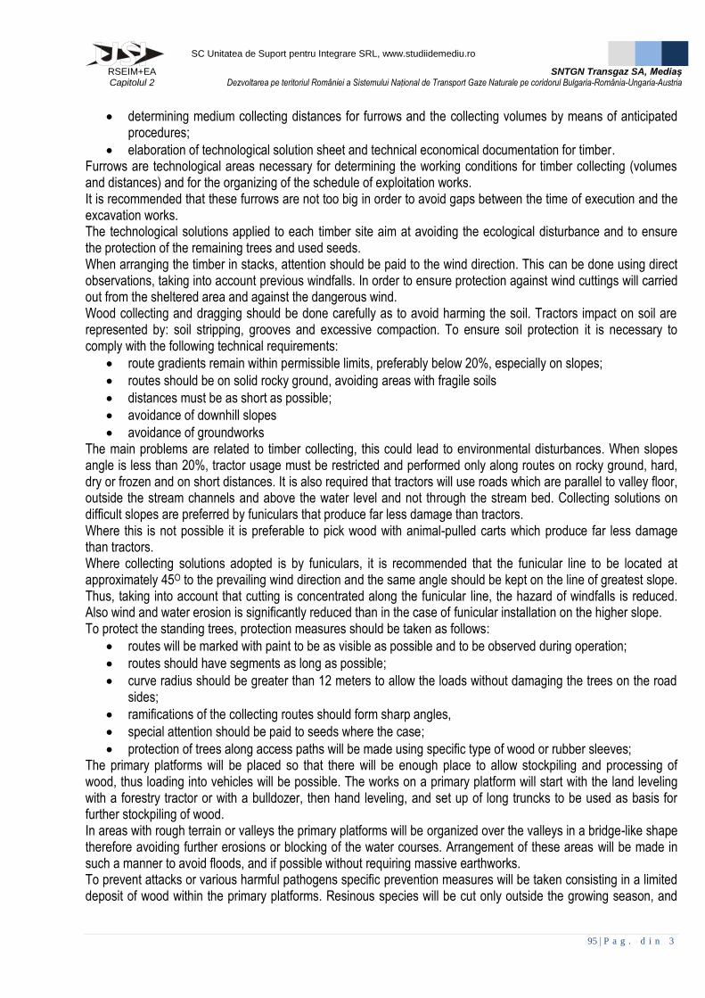
Lugoj pipe deposit is located in close proximity of Lugoj City, but far enough from residential areas which are found at about 1300m (including from Lugojel town). Access will be from DN6 (E70), from DJ680 County Road on a distance of about 1km and then on a vicinity road (exploitation road) on a distance of approximately 400m. Lugoj pipe deposit is located in n mainly agricultural area (arable), with industrial objectives nearby (deposits, gravel, etc.). Only brief organizational landworks and fencing are required for its arrangement.
Fig.2.XXIII. Lugoj pipe deposit (Timis County) [processed by
Google Earth ™]
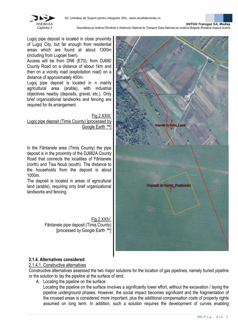
In the Fântanele area (Timiș County) the pipe deposit is in the proximity of the DJ682A County Road that connects the localities of Fântanele (north) and Tisa Nouă (south). The distance to the households from the deposit is about 1000m. The deposit is located in areas of agricultural land (arable), requiring only brief organizational landworks and fencing.
Fig.2.XXIV. Fântanele pipe deposit (Timiș County)
[processed by Google Earth ™]
2.1.4. Alternatives considered 2.1.4.1. Constructive alternatives Constructive alternatives assessed the two major solutions for the location of gas pipelines, namely buried pipeline or the solution to lay the pipeline at the surface of land.
A. Locating the pipeline on the surface Locating the pipeline on the surface involves a significantly lower effort, without the excavation / laying the pipeline underground phases. However, the social impact becomes significant and the fragmentation of the crossed areas is considered more important, plus the additional compensation costs of property rights assumed on long term. In addition, such a solution requires the development of curves enabling

SC Unitatea de Suport pentru Integrare SRL, www.studiidemediu.ro
RSEIM+EA Capitolul 2
SNTGN Transgaz SA, Mediaș Dezvoltarea pe teritoriul României a Sistemului Național de Transport Gaze Naturale pe coridorul Bulgaria-România-Ungaria-Austria
105 | P a g . d i n 3
expansions, or above- or under-crossing structures that ensure access on the sides. In addition to this solution, additional important safety solutions must be considered during operational phase. Regarding the impact on the environment, particular significance is reflected in the operational phase (operation) on:
- landscape: due to the contrast on the constitutive elements; - soil: the permanent occupation along the pipeline route, and loss of functions (agricultural, natural, etc.) of
major surfaces; - biodiversity: creating a major artificial barrier. B. The solution of buried pipeline
The buried solution requires an important financial as well as logistical and human effort, during construction phase. Taking into consideration that the operational phases (operation) are extended over 40 years, all impact categories and ecological footprint becomes extremely limited.
Thus, although the (economic) effort during the construction phase of BRUA project is one more important in terms of the solution adopted by burying the pipeline, it turns out to have a more limited long term impact on the environment. As for the solutions for under-crossing of water courses or major communication routes through horizontal drilling, which are extremely demanding from the technical point of view, this is a much less aggressive solution when referring to the ecological impact on riparian habitats. The impact for this chosen alternative is much more limited, present only at the two ends of the drilling areas placed on both sides of the watercourse. 2.1.4.1. Execution alternatives As for the execution alternatives, BRUA project does not involve complicated techniques or technologies. Stages of project execution make use of simple solutions, classical (excavation, welding, laying, etc.) thus, the alternatives are limited. In choosing alternatives (eg excavation), the energy efficiency of the machinery and equipment was taken into consideration. 2.1.5. The limit values of the techniques proposed by the owner and best available techniques The concept of good practice is defined as the peak of technological development in specific areas through the implementation of the latest scientific discoveries and by applying the most efficient solutions that involve achieving performance and extremely high efficiency, viable on long-term. Upon this based, the so-called BAT (Best Available Techniques = best available techniques) were defined for distinct technological fields as representing the current stage of development of processes, facilities or methods of operation which indicate how appropriate is a practical measure to limit emissions. BAT has also been defined by Directive 61/96 / EEC (Article 2) as:
- B „best” the most effective and advanced stage of development of activities and methods of appropriate operation, the particular techniques being considered appropriate and practical, mainly as a basis for setting emission limit values to prevent emissions and impact on the environment, or if this is not possible to reduce them;
- A „available” those techniques developed on a scale that, considering the relationship cost / benefit, enable application under economically and technically feasible conditions in the industrial sector concerned, whether the techniques are used or manufactured in the Member State concerned, as long as they remain accessible to the operator on reasonable costs;
- T „techniques” techniques and applied technology and how is the facility planned, constructed, operated and decommissioned are still the most effective achieving a high general level of environmental protection as a whole.
BATs is a materialization of the concept that the most effective solutions in achieving a project is proven to be also the most environmentally friendly, considering a long term approach. Practical application of advanced technologies in the implementation of projects inevitably lead to the assumption of high costs at the time of initial
SC Unitatea de Suport pentru Integrare SRL, www.studiidemediu.ro
RSEIM+EA Capitolul 2
SNTGN Transgaz SA, Mediaș Dezvoltarea pe teritoriul României a Sistemului Național de Transport Gaze Naturale pe coridorul Bulgaria-România-Ungaria-Austria
106 | P a g . d i n 3
investments, which comprise a range of measures to prevent the occurrence of risks and limit the propagation of pollutants. Such a preventive approach, meets a series of principles that underlie environmental law and policy, but also the sustainable development concept which aims at long-term economic growth. Prevention of adverse effects and taking the time to act in a prudent manner, is able to lead towards avoidance of environmental catastrophes, whose costs of remediation is most often extremely high, being able to compromise not only the very functioning of the project, but also a good part of society. BAT are defined by specific documents called BREF (= reference documents on best practices available). In the construction of pipelines there have not been drawn up codes of good practice. But relevant elements for this Project, as defined by the Code of Practice on the management of waste from construction and demolition, are reflected here. Within this document several relevant milestones can be pinpointed, mainly related to waste disposal. Thus, regardless of the category or type of site work, a good construction management involves:
Develop a waste management plan for each location / site / place of business;
Appoint a responsible person who will take responsibility for the waste generated on the site;
Involvement of management in these issues and personal communication with employees of the site;
Planning appropriate workspaces on site and providing areas for storage / handling of construction waste;
choice of appropriate equipment (hand tools, equipment and machines for demolition, lifting, loading, crushing, temporary storage location) and appropriate management of the site;
Storage and handling of building materials correctly and safely to prevent losses and material damage;
Keeping supplied products packaged until ready for use;
Auditing waste management activities;
Use of demolition techniques for maximum reuse and / or recycling. Assuming these measures represent an asset for the owner by:
Providing services and generating sustainable and viable economic alternatives;
Compliance with policies, laws and regulations on waste management;
Elimination of uncontrolled storage and unlawful practices (dumping); elimination of negative effects associated with the impact on the landscape, especially in suburban and rural areas;
Ensure better control of waste disposal and transportation costs;
Conservation of natural resources and reduce dependence on raw materials;
Reducing the volume of waste generated and disposed of (diverting from landfills);
Reducing the environmental impact of waste deposition and prevent inefficient exploitation of raw materials (especially for filling);
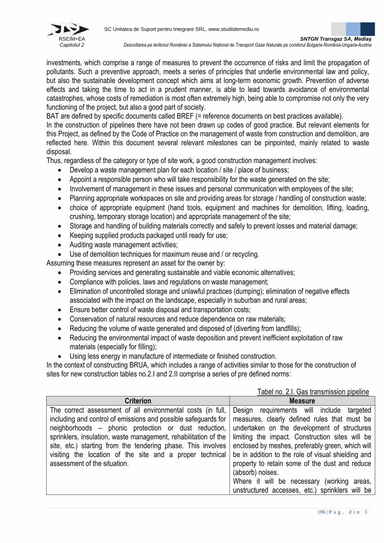
Using less energy in manufacture of intermediate or finished construction. In the context of constructing BRUA, which includes a range of activities similar to those for the construction of sites for new construction tables no.2.I and 2.II comprise a series of pre defined norms:
Tabel no. 2.I. Gas transmission pipeline
Criterion Measure
The correct assessment of all environmental costs (in full, including and control of emissions and possible safeguards for neighborhoods – phonic protection or dust reduction, sprinklers, insulation, waste management, rehabilitation of the site, etc.) starting from the tendering phase. This involves visiting the location of the site and a proper technical assessment of the situation.
Design requirements will include targeted measures, clearly defined rules that must be undertaken on the development of structures limiting the impact. Construction sites will be enclosed by meshes, preferably green, which will be in addition to the role of visual shielding and property to retain some of the dust and reduce (absorb) noises. Where it will be necessary (working areas, unstructured accesses, etc.) sprinklers will be

SC Unitatea de Suport pentru Integrare SRL, www.studiidemediu.ro
RSEIM+EA Capitolul 2
SNTGN Transgaz SA, Mediaș Dezvoltarea pe teritoriul României a Sistemului Național de Transport Gaze Naturale pe coridorul Bulgaria-România-Ungaria-Austria
107 | P a g . d i n 3
Criterion Measure
installed. Subsequent to the completion of works, the land will be reinstated to its original use and ecological reconstruction works will be assumed. For the pre-construction stage when work sites will be in place for each sector there will be a protocol that will establish as accurately as possible the environmental load, based on standardized forms (standard-forms), with aerial photographs or photographic images taken from the ground, which will act as control elements. For each site during the growing season (May-September the ecological structure and functions of the site will be accurately determined.
A precise assessment of the types and quantities of waste generated, particularly the hazardous ones.
An assessment of the quantities of waste was performed for each site individually, thereby facilitating the evaluation and quantification of waste generated.
Evaluation of services available in the area for transport, treatment, recovery and disposal. Complying with the rules of the local waste management authority (although usually lacking, the number of localities that promotes local council decisions for this area is growing).
Waste management solution will be assessed for each UAT, and contacts will be elaborated with the authorities entrusted with these responsibilities for each type of waste separately.
Contracts (or subcontracting) will clearly define the obligations, based on records and waste management.
It will contractually perfect one for each type of waste separately. Entrepreneurs will keep track of the waste.
How to take responsibility for the land of the site and accountability for breach of accidental pollution provisions.
Works organizations will be established by accurate legal documents that will determine the distinct responsibilities of entrepreneurs, assumed compensation, but also the breach to restore them to the initial state. Based on these documents, environmental liabilities will be clearly defined in the protocols of pre-defining environmental tasks undertaken. Thus, the principles underlying the specific legislation in force (especially the principle: the polluter pays), the contractor will undertake to remedy any fault of its negative effects.
Adapting existing procedures in the quality management system and environment to the specific site or, failing that, the conditions of the regulatory acts issued by the authorities (Environmental Agreement, Opinion water management, Opinion sanitary or PSI if applicable) on this aspect.
One of the conditions connected with the selection of contractors will be represented by the certification of ISO9001, ISO14001 respectively (or equivalent), ensuring thereby taking existing procedures in the quality management system and environment.
SC Unitatea de Suport pentru Integrare SRL, www.studiidemediu.ro
RSEIM+EA Capitolul 2
SNTGN Transgaz SA, Mediaș Dezvoltarea pe teritoriul României a Sistemului Național de Transport Gaze Naturale pe coridorul Bulgaria-România-Ungaria-Austria
108 | P a g . d i n 3
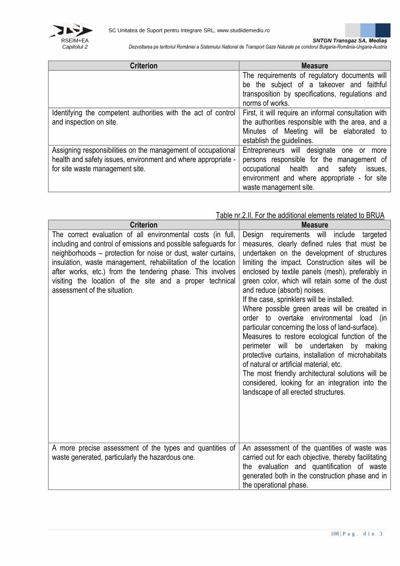
Criterion Measure
The requirements of regulatory documents will be the subject of a takeover and faithful transposition by specifications, regulations and norms of works.
Identifying the competent authorities with the act of control and inspection on site.
First, it will require an informal consultation with the authorities responsible with the area, and a Minutes of Meeting will be elaborated to establish the guidelines.
Assigning responsibilities on the management of occupational health and safety issues, environment and where appropriate - for site waste management site.
Entrepreneurs will designate one or more persons responsible for the management of occupational health and safety issues, environment and where appropriate - for site waste management site.
Table nr.2.II. For the additional elements related to BRUA
Criterion Measure
The correct evaluation of all environmental costs (in full, including and control of emissions and possible safeguards for neighborhoods – protection for noise or dust, water curtains, insulation, waste management, rehabilitation of the location after works, etc.) from the tendering phase. This involves visiting the location of the site and a proper technical assessment of the situation.
Design requirements will include targeted measures, clearly defined rules that must be undertaken on the development of structures limiting the impact. Construction sites will be enclosed by textile panels (mesh), preferably in green color, which will retain some of the dust and reduce (absorb) noises. If the case, sprinklers will be installed. Where possible green areas will be created in order to overtake environmental load (in particular concerning the loss of land-surface). Measures to restore ecological function of the perimeter will be undertaken by making protective curtains, installation of microhabitats of natural or artificial material, etc. The most friendly architectural solutions will be considered, looking for an integration into the landscape of all erected structures.
A more precise assessment of the types and quantities of waste generated, particularly the hazardous one.
An assessment of the quantities of waste was carried out for each objective, thereby facilitating the evaluation and quantification of waste generated both in the construction phase and in the operational phase.

SC Unitatea de Suport pentru Integrare SRL, www.studiidemediu.ro
RSEIM+EA Capitolul 2
SNTGN Transgaz SA, Mediaș Dezvoltarea pe teritoriul României a Sistemului Național de Transport Gaze Naturale pe coridorul Bulgaria-România-Ungaria-Austria
109 | P a g . d i n 3
Criterion Measure
Evaluation of services available in the area for transport, treatment, recovery and disposal. Observing the rules of the local waste management authority (although usually lacking, the number of localities that promote local council decisions for this area is growing).
In each UAT waste management solution will be assessed, and contracts with entities entrusted with these responsibilities for each type of waste separately will be elaborated.
Contracts (or subcontracting) will clearly define the obligations, based on records and waste management.
One contract will be elaborated for each type of waste separately. Operators will keep track of the waste.
How to take the responsibility of the land of the site and accountability for breach of accidental pollution provisions.
Works sites will be subject to legally binding documents that will ensure the transfer of ownership. Based on these documents, environmental responsibilities are specifically defined to be transferred to the entrepreneurs and subsequently to the beneficiary, following the responsibilities for each stage to be clearly defined and assumed.
Adapting existing procedures in the quality management system and environment to the site or, if missing, the conditions of the regulatory acts issued by the authorities (Environmental Agreement, Opinion water management, Opinion sanitary or PSI if applicable) on this aspect.
One of the conditions connected with the selection of contractors will be represented and certification of ISO9001, ISO14001 respectively (or equivalent), ensuring thereby taking existing procedures in the quality management system and environment. The requirements of regulatory documents will be the subject of a takeover and faithful transposition by specifications, regulations and norms of elaborated works.
Identifying the competent authorities with the act of control and inspection on site.
It will require a first phase, an informal consultation with the authorities responsible in the area, and a Minutes of Meeting will be elaborated to establish the guidelines.
Assigning responsibilities on the management of occupational health and safety issues, environment and where appropriate - for site waste management site.
Entrepreneurs will designate one or more persons responsible for the management of occupational health and safety issues, environment and where appropriate - for site waste management site.
2.2. Decommissioning activities Activities related to the decommissioning of a project involve removal of all the parts of it, followed by measures for a complete restoration of the environmental works at a state as close as their original state (or even natural - if it goes to ecological restoration). So perhaps the most consistent component of this phase is the one dedicated to the component of ecological reconstruction of locations.

SC Unitatea de Suport pentru Integrare SRL, www.studiidemediu.ro
RSEIM+EA Capitolul 2
SNTGN Transgaz SA, Mediaș Dezvoltarea pe teritoriul României a Sistemului Național de Transport Gaze Naturale pe coridorul Bulgaria-România-Ungaria-Austria
110 | P a g . d i n 3
There are four major types of ecological reconstruction: a. The natural regeneration or passive regeneration b. Eu-restoration (true restoration, complete restoration) or complete reconstruction c. Partial Restoration or ecological rehabilitation d. Restoring by substitution or ecological reconstruction
The type of reconstruction is chosen depending on the degree of habitat degradation and the needs of the target. First two types are recommended in protected areas natural regeneration or passive regeneration and eu-restoration. Ecological restoration is adopted where ecological reconstruction measures are aiming at a complete and detailed restoration of all the components of ecological communities, to be replicated as faithfully as possible and driving dynamics functions close to the natural status. Decommissioning of the parts of BRUA can be addressed only in a theoretical manner, the project itself is conceived as a project to develop an infrastructure to be used on a very long term. During operation (estimated at 40 years) on BRUA pipeline, maintenance activities will be undertaken, as well as maintenance works, reconditioning (valve stations, gas compressor stations), removing therefore further risks caused by interventions or remediation of failures. Transmission networks are widely expanded at global level representing an extremely valuable logistic resource. It is expected that in the future after depletion of natural gas resources, following a recondition process and other fluids or gases could be used, such as hydrogen. 2.2.1. Description BRUA decommissioning will involve removing the pipes recycling and dismantling / demolition of pipeline components and ancillary elements (valve stations, gas compressor stations). An alternative regarding the GCSs is represented by the possibility to change their destination and to introduce them again in the socio-economic circuit and to make full use of the newly created infrastructure. Decommissioning procedures will be preceded by a regulatory stage in accordance to the legal provisions. 2.2.1.1. Decommissioning of gas transmission pipelines Disposal of natural gas pipelines involves the following steps:
- Emptying of pipeline sections through the recovery of gas content by use of transfer pumps; - Venting of pipeline sections by opening the valves and purging from one end of the pipeline by
pressurized air to remove possible residual gas pockets; - Inspection of the pipeline route; - Preparation of the ground by organizing access roads and temporary removal of obstacles (relocation)
and shrub vegetation; - Identification and mapping of underground pipeline route using metal detectors (or other dedicated
techniques); - Removal of soil cover on a 21m width strip and its temporary storage in close proximity to the site; - Excavation of soil in the proximity of the pipeline; - Removal by manual digging of the soil covering the top of the pipeline; - Perforation of the pipeline every 10m, with a low speed drill, and the drilling areas will be permanently
under a water jet to prevent overheating and sparks; pipeline sections will be vented for at least 24 hours; - A water-jet cut will be performed in order to allow cleaning of residues deposited on the bottom of the pipe;
debris will be collected in special designation containers; - Further excavation on one side of the pipeline with a narrow bucket (max. 50 cm) excavator up to the
maximum diameter of the pipe; - Attachment of anchorage hooks by welding; - Lifting of the pipeline sections with pipe launchers; operation will be conducted by gradual lifting, using at
least 4 launchers that will operate the pipeline similarly step by step, gradually raising one segment section after another. Under the lifted sections supporting metal beams in a bridge-like structure will be

SC Unitatea de Suport pentru Integrare SRL, www.studiidemediu.ro
RSEIM+EA Capitolul 2
SNTGN Transgaz SA, Mediaș Dezvoltarea pe teritoriul României a Sistemului Național de Transport Gaze Naturale pe coridorul Bulgaria-România-Ungaria-Austria
111 | P a g . d i n 3
installed, enabling the segments cutting and therefore allowing easy shipping or reuse for other purposes; there is also the option to recover the metal by melting. If this melting option is selected a prior removal of protective coats is required by milling or by use of thermal processes.
- Once completed, the dismantling morphological recovery of soil operations will be initiated, including topsoil laying, primary processed vegetable debris intended to help germination so as to return the soil to its initial state (before the Project). There will be seeding works, overseeding and re-planting of woody species, as appropriate. In order to reduce the environmental footprint and to accelerate the ecological restoration processes where necessary, there will be microstructures able to accelerate the pace of colonization, so as to ensure growth indices of biodiversity and thus to regain a stable balance of ecological communities affected. In order to reduce the impact associated to BRUA, further work will be carried out consisting of environmental reconstruction of the affected areas in close proximity to BRUA, that would guarantee long-term preservation of environmental integrity (especially land). Such works are: re-vegetation, planting of shrubs and woody species, and the installation of microstructures (microhabitats) of natural materials (rocks, piles of dead branches, etc.) or artificial materials (shelter houses, feeders, etc.) all aimed to accelerate the pace of colonization, growth indices of biodiversity and thus to regain a stable balance of the ecological communities affected.
- When works are completed, a monitoring program will be assumed in order to validate the reclamation process. Where insufficiently treated elements will be identified, suitable remediation actions will be taken continuing the interventions program, until all negative effects are removed.
- On the pipeline route, all supporting elements made of massive concrete will be crushed, and the material evacuated.
2.2.1.2. Disposal of constructive elements of BRUA - Disposal of constructive elements along BRUA will be achieved by disassembly / demolition; - The land will be returned to the agricultural circuit or (semi) natural circuit; - A realistic option is to use technological buildings (GCS) for other socio-economic activities, subsequent
change of destination and functional reconfiguration. 2.2.2. Substances contained / stored (including asbestos and PCBs) During the stages of decommissioning, the resulting materials are to be selected by category, placed in adequate intermediate storages, to be returned to the economic circuit (recycling). Most of the items are steel pipe. For the entire project, pipes and fittings to be installed total an aggregate weight of about 111 873 t. The insulation layer that protects the pipes is composed of a series of epoxy resin and polyethylene HDPE membrane 21809-1. The interior of the steel pipe is protected by an inert inner layer composed of epoxy resin and HDPE polyethylene 21809-1. BRUA does not use materials or components containing asbestos and PCBs. 2.2.3. Measures, equipment and protective conditions The safety measures, equipment and protection requirements in the decommissioning phase are the usual ones for construction sites. The safety measures will comply with industry regulations and requirements, aiming in particular the following:
- Acknowledgement by the project beneficiary that all parties involved in the implementation and operation of the project comply with the provisions related to work safety and health;
- There is an appropriately structured compartment for work safety, either as part of an existing one, or an independent one, to performing specific tasks;
- The criteria for organization and operation of the department of labor protection are established; - The legal provisions on employment and assignment of employed personnel are complied with;

SC Unitatea de Suport pentru Integrare SRL, www.studiidemediu.ro
RSEIM+EA Capitolul 2
SNTGN Transgaz SA, Mediaș Dezvoltarea pe teritoriul României a Sistemului Național de Transport Gaze Naturale pe coridorul Bulgaria-România-Ungaria-Austria
112 | P a g . d i n 3
- The health examination calendar is fully complied with, which is adapted in terms of complexity to the specific personnel's employment target, aiming to go through all the diagnostic methods to detect the entire spectrum of illnesses associated;
- Assurance of an appropriate safety training of all personnel involved, performed by a suitably qualified and specialized staff;
- Carrying out of a constant medical checks, preventing thus the installation and the severity of the effects related to the personnel’s physical and mental exhaustion;
- Taking of full measures of warning, signaling and marking of risk across the functional structure of the project;
- The personnel involved will use complete protective equipment and gear; - All parts of BRUA are completed, documented and described by manuals and in technical sheets; - All workplaces and workstations during construction and operation are adequately assured both in terms
of protection, safety and health as well as regarding the social-care; - During operation first aid point will be organized on site, and will be properly equipped especially for cases
of multiple accidental trauma or deep burns (caused by improper handling of welding equipment). - During operation, within GCSs, but also in the areas near valve stations, there will be first aid points,
properly equipped especially for cases of multiple accidental trauma and burns (caused by accidental explosions);
Labor safety equipment will be available to all personnel involved in all stages of construction, operation (and decommissioning) of BRUA, according to the norms of each workstation. The protective work equipment - whether common or individual facilities - will be regularly checked, to be replaced as soon as there is a deficiency of any kind.