Chapter 2 Part C: Engine removal and general overhaul...
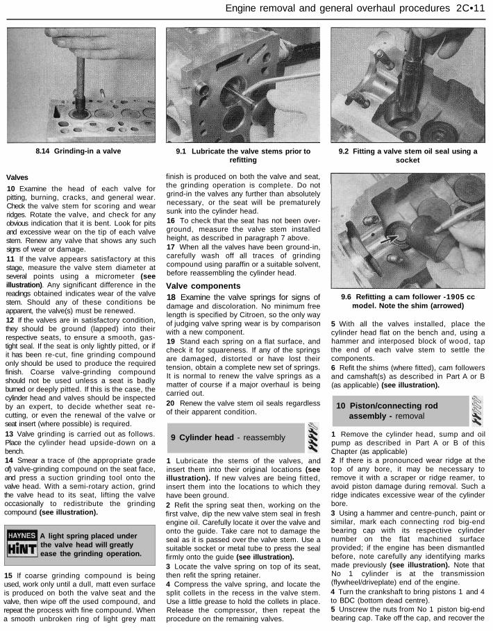
24
Chapter 2 Part C: Engine removal and general overhaul procedures Contents Crankshaft - inspection 14 Crankshaft - refitting and main bearing running clearance check ..18 Crankshaft - removal 11 Cylinder block/crankcase - cleaning and inspection 12 Cylinder head - dismantling 7 Cylinder head - reassembly 9 Cylinder head and valves - cleaning and inspection 8 Engine - initial start-up after overhaul 20 Engine and automatic transmission - removal, separation and refitting 5 Engine and manual transmission - removal, separation and refitting 4 Degrees of difficulty Engine overhaul - dismantling sequence 6 Engine overhaul - general information 2 Engine overhaul - reassembly sequence 16 Engine/transmission removal - methods and precautions 3 General information 1 Main and big-end bearings - inspection 15 Piston/connecting rod assembly - inspection 13 Piston/connecting rod assembly - refitting and big-end bearing running clearance check 19 Piston/connecting rod assembly - removal 10 Piston rings - refitting 17 Easy, suitable for novice with little experience Fairly easy, suitable for beginner with some experience Fairy difficult, suitable for competent DIY mechanic Difficult, suitable for experienced DIY mechanic Very difficult, suitable for expert DIY or professional Specifications Note: At the time of writing, many specifications for the 1761 cc and 1998 cc engines were not available. Where the relevant specifications are not given here, refer to your Citroen dealer for further information. Cylinder head Maximum gasket face distortion 0.05 mm Cylinder head height: Standard: 1124 cc and 1360 cc engines 111.2 ± 0.08 mm 1580 cc, 1761 cc, 1905 cc and 1998 cc 8-valve engines 141.0 ± 0.05 mm 1998 cc 16-valve engine 132.0 ± 0.15 mm Minimum after refinishing: 1124 cc and 1360 cc engines 111.0 mm 1580 cc, 1761 cc, 1905 cc and 1998 cc 8-valve engines 140.8 mm 1998 cc 16-valve engine 131.85 mm Pistons Piston diameter: 1124 cc engine: SizegroupA 71.940 ± 0.010 mm Size group B 71.950 ± 0.010 mm Size group C 71.960 ± 0.010 mm 1360 cc engine: Size group A 74.950 ± 0.010 mm Size group B 74.960 ± 0.010 mm Size group C 74.970 ± 0.010 mm 1580 cc, 1761 cc and 1905 cc engines: Size group A 82.960 ± 0.007 mm Size group B 82.970 ± 0.007 mm Size group C 82.980 ± 0.007 mm 1998 cc engines Not available 2C•1
Transcript of Chapter 2 Part C: Engine removal and general overhaul...

Chapter 2 Part C:Engine removal and general overhaul proceduresContentsCrankshaft - inspection 14Crankshaft - refitting and main bearing running clearance check . . 1 8Crankshaft - removal 11Cylinder block/crankcase - cleaning and inspection 12Cylinder head - dismantling 7Cylinder head - reassembly 9Cylinder head and valves - cleaning and inspection 8Engine - initial start-up after overhaul 20Engine and automatic transmission - removal, separation and
refitting 5Engine and manual transmission - removal, separation and
refitting 4
Degrees of difficulty
Engine overhaul - dismantling sequence 6Engine overhaul - general information 2Engine overhaul - reassembly sequence 16Engine/transmission removal - methods and precautions 3General information 1Main and big-end bearings - inspection 15Piston/connecting rod assembly - inspection 13Piston/connecting rod assembly - refitting and big-end bearing
running clearance check 19Piston/connecting rod assembly - removal 10Piston rings - refitting 17
Easy, suitable fornovice with littleexperience
Fairly easy, suitablefor beginner withsome experience
Fairy difficult, suitablefor competent DIYmechanic
Difficult, suitable forexperienced DIYmechanic
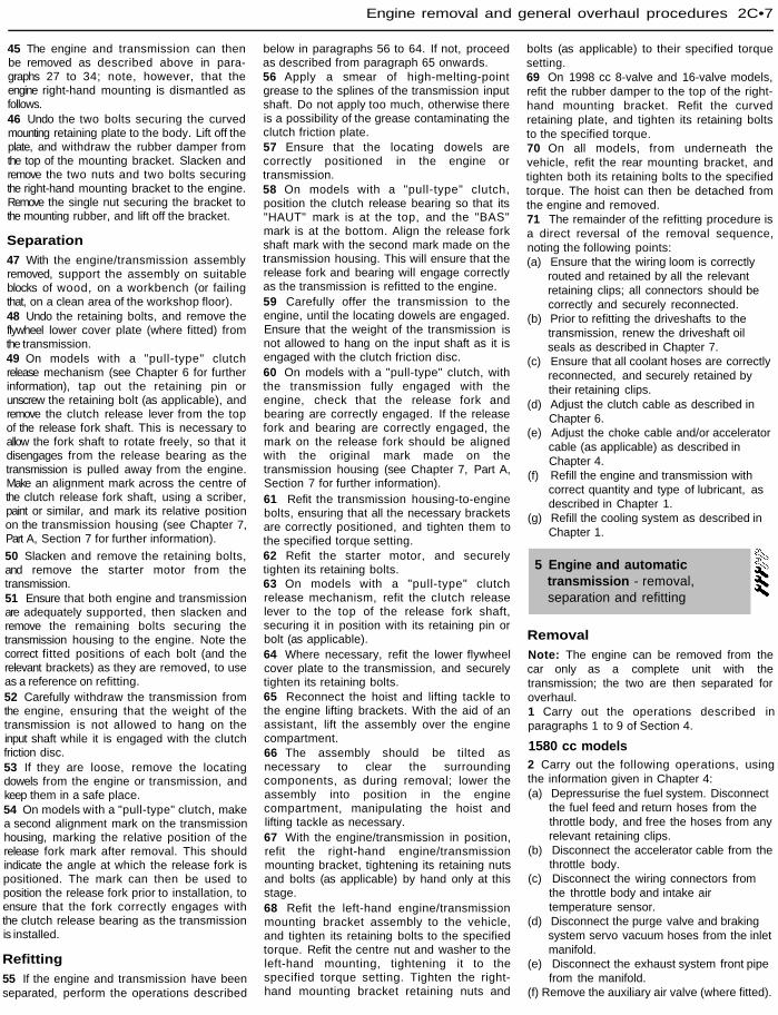
Very difficult,suitable for expert DIYor professional
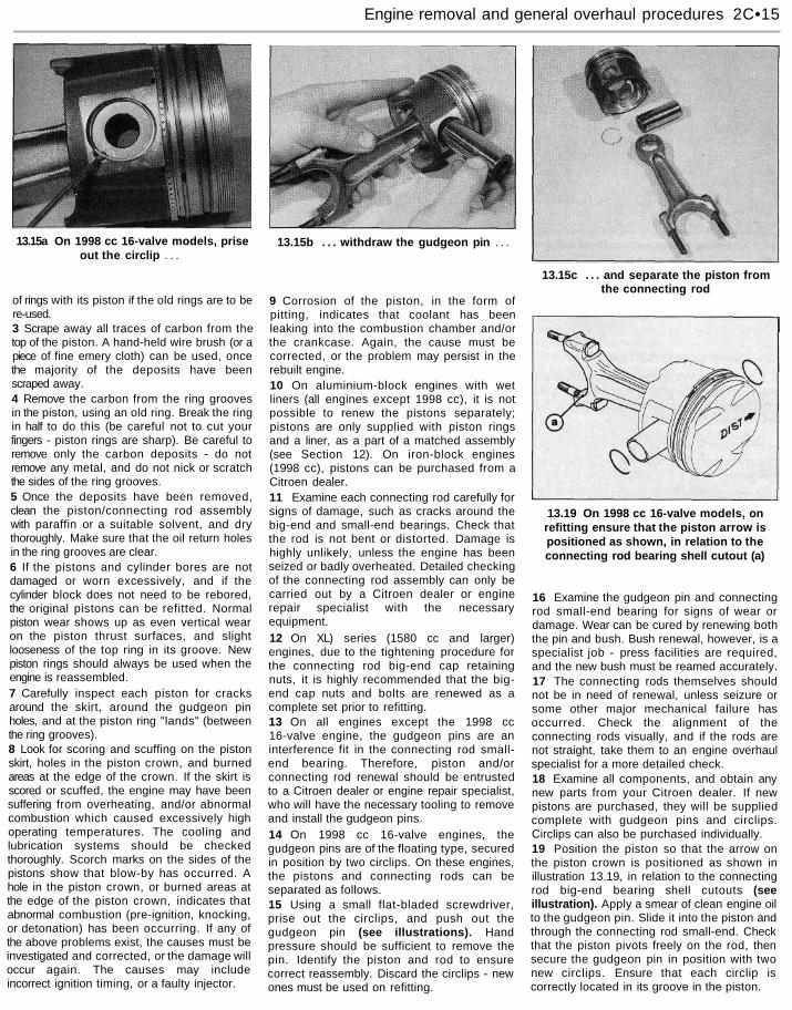
SpecificationsNote: At the time of writing, many specifications for the 1761 cc and 1998 cc engines were not available. Where the relevant specifications are notgiven here, refer to your Citroen dealer for further information.
Cylinder headMaximum gasket face distortion 0.05 mmCylinder head height:
Standard:1124 cc and 1360 cc engines 111.2 ± 0.08 mm1580 cc, 1761 cc, 1905 cc and 1998 cc 8-valve engines 141.0 ± 0.05 mm1998 cc 16-valve engine 132.0 ± 0.15 mm
Minimum after refinishing:1124 cc and 1360 cc engines 111.0 mm1580 cc, 1761 cc, 1905 cc and 1998 cc 8-valve engines 140.8 mm1998 cc 16-valve engine 131.85 mm
PistonsPiston diameter:
1124 cc engine:SizegroupA 71.940 ± 0.010 mmSize group B 71.950 ± 0.010 mmSize group C 71.960 ± 0.010 mm
1360 cc engine:Size group A 74.950 ± 0.010 mmSize group B 74.960 ± 0.010 mmSize group C 74.970 ± 0.010 mm
1580 cc, 1761 cc and 1905 cc engines:Size group A 82.960 ± 0.007 mmSize group B 82.970 ± 0.007 mmSize group C 82.980 ± 0.007 mm
1998 cc engines Not available
2C•1
2C•2 Engine removal and general overhaul procedures
Cylinder blockCylinder bore diameter:
1124 cc engine:Size group A 72.000 to 72.010 mmSize group B 72.010 to 72.020 mmSize group C 72.020 to 72.030 mm
1360 cc engine:Size group A 75.000 to 75.010 mmSize group B 75.010 to 75.020 mmSize group C 75.020 to 75.030 mm
1580 cc, 1761 cc and 1905 cc engines:Size group A 83.000 to 83.010 mmSize group B 83.010 to 83.020 mmSize group C 83.020 to 83.030 mm
1998 cc engines Not available (86 mm nominal)Liner protrusion above block mating surface - aluminium-block engine (ie all except 1998 cc) only:
Standard 0.03 to 0.10 mmMaximum difference between any two liners 0.05 mm
CrankshaftEndfloat 0.07 to 0.32 mmMain bearing journal diameter:
1124 cc and 1360 cc engines:Standard 49.965 to 49.981 mmUndersize 49.665 to 49.681 mm
1580 cc and 1905 cc engines:Standard 59.981 to 60.000 mmUndersize 59.681 to 59.700 mm
1761 cc and 1998 cc engines Not availableBig-end bearing journal diameter:
1124 cc and 1360 cc engines:Standard 44.975 to 45.000 mmUndersize 44.675 to 44.700 mm
1580 cc and 1905 cc engines:Standard 49.984 to 50.000 mmUndersize 49.684 to 49.700 mm
1761 cc and 1998 cc engines Not availableMaximum bearing journal out-of-round (all models) 0.007 mmMain bearing running clearance:
1124 cc and 1360 cc models*:Pre-February 1992 models 0.023 to 0.083 mmFebruary 1992-on models 0.023 to 0.048 mm
1580 cc, 1761 ccand1905 cc engines** 0.025 to 0.050 mm1998 cc engines 0.038 to 0.069 mm
Big-end bearing running clearance - all models** 0.025 to 0.050 mm*On 1124 ccand 1360 cc models, the main bearing shells were modified in February 1992, resulting in a reduction in the specified runningclearance - see text for further information.**These are suggested figures, typical for this type of engine - no exact values are stated by Citroen.
Piston ringsEnd gaps:
Top compression ring:1124 cc engine 0.25 to 0.45 mm1360 cc engine 0.3 to 0.5 mm1580 cc engine 0.4 to 0.6 mm1905 cc engine 0.2 to 0.4 mm1761 cc and 1998 cc engines* 0.3 to 0.5 mm
Second compression ring:1124 cc engine 0.25 to 0.45 mm1360 cc engine 0.3 to 0.5 mm1580 cc and 1905 cc engines 0.15 to 0.35 mm1761 cc and 1998 cc engines* 0.3 to 0.5 mm
Oil control ring:1124 cc engine 0.20 to 0.45 mmAll other models* 0.3 to 0.5 mm
*These are suggested figures, typical for this type of engine - no exact values are stated by Citroen.
Engine removal and general overhaul procedures 2C•3
Connecting rodsMaximum weight difference between any two piston/connecting rod assemblies:
1124 cc and 1360 cc engines 5.0 g1580 cc, 1761 cc and 1905 cc engines 13.0 g1998 cc engines 7.0 g
ValvesValve head diameter:
Inlet:1124 cc and 1360 cc engines 36.8 mm1580 cc engine 41.6 mm1761 cc engine Not available1905 cc engine 41.8 mm1998 cc 8-valve engine 42.6 mm1998 cc 16-valve engine 34.7 mm
Exhaust:1124 cc and 1360 cc engines : ,, 29.4 mm1580 cc and 1905 cc engines 34.7 mm1761 cc engine Not available1998 cc 8-valve engine 34.5 mm1998 cc 16-valve engine 29.7 mm
Valve stem diameter:Inlet:
1124 cc and 1360 cc engines 6.84 to 6.99 mm1580 cc and 1905 cc engines 7.83 to 7.98 mm1761 cc and 1998 cc engines Not available
Exhaust:1124 cc and 1360 cc engines 6.83 to 6.98 mm1580 cc and 1905 cc engines 7.83 to 7.98 mm1761 cc and 1998 cc engines Not available
Overall length:Inlet:
1124 cc and 1360 cc engines 112.76 ± 0.25 mm1580 cc and 1905 cc engines 108.79 ± 0.1 mm1761 cc and 1998 cc engines Not available
Exhaust:1124 cc and 1360 cc engines 112.56 ± 0.25 mm1580 cc and 1905 cc engines 108.37 ± 0.1 mm1761 cc and 1998 cc engines Not available
Torque wrench settingsTU series engine - 1124 cc and 1360 ccRefer to Chapter 2 Part A Specifications
XU series engine - 1580 cc and largerRefer to Chapter 2 Part B Specifications
1 General information
Included in this Part of Chapter 2 are detailsof removing the engine/transmission from thecar and general overhaul procedures for thecylinder head, cylinder block/crankcase andall other engine internal components.
The information given ranges from adviceconcerning preparation for an overhaul andthe purchase of replacement parts, to detailedstep-by-step procedures covering removal,inspection, renovation and refitting of engineinternal components.
After Section 6, all instructions are basedon the assumption that the engine has beenremoved from the car. For informationconcerning in-car engine repair, as well as theremoval and refitting of those external
components necessary for full overhaul, referto Part A or B of this Chapter (as applicable)and to Section 6. Ignore any preliminarydismantling operations described in Part A(1124 cc and 1360 cc models) or Part B (1580cc and larger models) that are no longerrelevant once the engine has been removedfrom the car.
Apart from torque wrench settings, whichare given at the beginning of Part A or Part B,all specifications relating to engine overhaulare at the beginning of this Part of Chapter 2.
It is not always easy to determine when, orif, an engine should be completelyoverhauled, as a number of factors must beconsidered.
High mileage is not necessarily anindication that an overhaul is needed, whilelow mileage does not preclude the need for anoverhaul. Frequency of servicing is probablythe most important consideration. An enginewhich has had regular and frequent oil andfilter changes, as well as other requiredmaintenance, should give many thousands ofmiles of reliable service. Conversely, aneglected engine may require an overhaulvery early in its life.
Excessive oil consumption is an indicationthat piston rings, valve seals and/or valveguides are in need of attention. Make surethat oil leaks are not responsible beforedeciding that the rings and/or guides areworn. Perform a compression test, asdescribed in Part A of this Chapter, todetermine the likely cause of the problem.
Check the oil pressure with a gauge fitted inplace of the oil pressure switch, and compare
2 Engine overhaul -general information
2C•4 Engine removal and general overhaul procedures
it with that specified. If it is extremely low, themain and big-end bearings, and/or the oilpump, are probably worn out.
Loss of power, rough running, knocking ormetallic engine noises, excessive valve gearnoise, and high fuel consumption may alsopoint to the need for an overhaul, especially ifthey are all present at the same time. If acomplete service does not remedy thesituation, major mechanical work is the onlysolution.
An engine overhaul involves restoring allinternal parts to the specification of a newengine. During an overhaul, the cylinder liners(where applicable), the pistons and the pistonrings are renewed. New main and big-endbearings are generally fitted; if necessary, thecrankshaft may be renewed, to restore thejournals. The valves are also serviced as well,since they are usually in less-than-perfectcondition at this point. While the engine isbeing overhauled, other components, such asthe distributor, starter and alternator, can beoverhauled as well. The end result should bean as-new engine that will give many trouble-free miles.
Note: Critical cooling system componentssuch as the hoses, thermostat and waterpump should be renewed when an engine isoverhauled. The radiator should be checkedcarefully, to ensure that it is not clogged orleaking. Also, it is a good idea to renew the oilpump whenever the engine is overhauled.
Before beginning the engine overhaul, readthrough the entire procedure, to familiariseyourself with the scope and requirements ofthe job. Overhauling an engine is not difficult ifyou follow carefully all of the instructions,have the necessary tools and equipment, andpay close attention to all specifications. It can,however, be time-consuming. Plan on the carbeing off the road for a minimum of twoweeks, especially if parts must be taken to anengineering works for repair or reconditioning.Check on the availability of parts and makesure that any necessary special tools andequipment are obtained in advance. Mostwork can be done with typical hand tools,although a number of precision measuringtools are required for inspecting parts todetermine if they must be renewed. Often theengineering works will handle the inspectionof parts and offer advice concerningreconditioning and renewal.
Note: Always wait until the engine has beencompletely dismantled, and until allcomponents (especially the cylinderblock/crankcase and the crankshaft) havebeen inspected, before deciding what serviceand repair operations must be performed byan engineering works. The condition of thesecomponents will be the major factor toconsider when determining whether tooverhaul the original engine, or to buy areconditioned unit. Do not, therefore,purchase parts or have overhaul work done onother components until they have beenthoroughly inspected. As a general rule, time
is the primary cost of an overhaul, so it doesnot pay to fit worn or sub-standard parts.
As a final note, to ensure maximum life andminimum trouble from a reconditioned engine,everything must be assembled with care, in aspotlessly-clean environment.
1 If you have decided that the engine must beremoved for overhaul or major repair work,several preliminary steps should be taken.2 Locating a suitable place to work isextremely important. Adequate work space,along with storage space for the car, will beneeded. If a workshop or garage is notavailable, at the very least, a flat, level, cleanwork surface is required.3 Cleaning the engine compartment andengine/transmission before beginning theremoval procedure will help keep tools cleanand organized.4 An engine hoist or A-frame will also benecessary. Make sure the equipment is ratedin excess of the combined weight of theengine and transmission. Safety is of primaryimportance, considering the potential hazardsinvolved in lifting the engine/transmission outof the car.5 If this is the first time you have removed anengine, an assistant should ideally beavailable. Advice and aid from someone moreexperienced would also be helpful. There aremany instances when one person cannotsimultaneously perform all of the operationsrequired when lifting the engine out of thevehicle.6 Plan the operation ahead of time. Beforestarting work, arrange for the hire of or obtainall of the tools and equipment you will need.Some of the equipment necessary to performengine/transmission removal and installationsafely and with relative ease (in addition to anengine hoist) is as follows: a heavy duty trolleyjack, complete sets of spanners and socketsas described in the front of this manual,wooden blocks, and plenty of rags andcleaning solvent for mopping up spilled oil,coolant and fuel. If the hoist must be hired,
make sure that you arrange for it in advance,and perform all of the operations possiblewithout it beforehand. This will save youmoney and time.7 Plan for the car to be out of use for quite awhile. An engineering works will be requiredto perform some of the work which the do-it-yourselfer cannot accomplish without specialequipment. These places often have a busyschedule, so it would be a good idea toconsult them before removing the engine, inorder to accurately estimate the amount oftime required to rebuild or repair componentsthat may need work.8 Always be extremely careful when removingand refitting the engine/transmission. Seriousinjury can result from careless actions. Planahead and take your time, and a job of thisnature, although major, can be accomplishedsuccessfully.
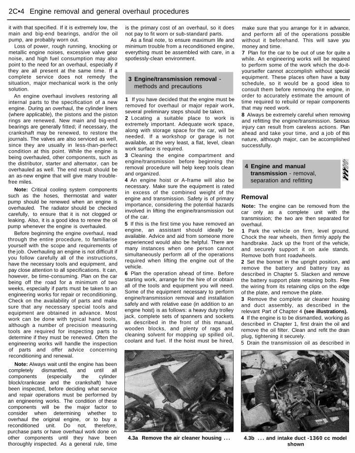
RemovalNote: The engine can be removed from thecar only as a complete unit with thetransmission; the two are then separated foroverhaul.1 Park the vehicle on firm, level ground.Chock the rear wheels, then firmly apply thehandbrake. Jack up the front of the vehicle,and securely support it on axle stands.Remove both front roadwheels.2 Set the bonnet in the upright position, andremove the battery and battery tray asdescribed in Chapter 5. Slacken and removethe battery support plate retaining bolts. Freethe wiring from its retaining clips on the edgeof the plate, and remove the plate.3 Remove the complete air cleaner housingand duct assembly, as described in therelevant Part of Chapter 4 (see illustrations).4 If the engine is to be dismantled, working asdescribed in Chapter 1, first drain the oil andremove the oil filter. Clean and refit the drainplug, tightening it securely.5 Drain the transmission oil as described in
4.3a Remove the air cleaner housing . . . 4.3b . . . and intake duct -1360 cc modelshown
3 Engine/transmission removal -methods and precautions
4 Engine and manualtransmission - removal,separation and refitting
Engine removal and general overhaul procedures 2C•5
Chapter 1. Refit the drain and filler plugs, andtighten them to their specified torque settings.6 Remove the alternator as described inChapter 5.7 Where applicable, remove the powersteering pump as described in Chapter 10.8 On models with air conditioning, unbolt thecompressor, and position it clear of theengine unit. Support the weight of thecompressor by tying it to the vehicle body, toprevent any excess strain being placed on thecompressor lines whilst the engine isremoved. Do not disconnect the refrigerantlines from the compressor (refer to thewarnings given in Chapter 3).9 Drain the cooling system (see Chapter 1),saving the coolant if it is fit for re-use.Although not essential, it may also be worthremoving the radiator (Chapter 3), which iseasily damaged during engine removal.
1124 cc and 1360 cc models10 On carburettor models, carry out thefollowing operations, using the informationgiven in Chapter 4:(a) Disconnect the fuel feed hose from the
anti-percolation chamber.(b) Disconnect the accelerator and choke
cables from the carburettor.(c) Disconnect the braking system servo
vacuum hose from the inlet manifold.(d) Remove the exhaust system front pipe.11 On fuel injection models, carry out thefollowing operations, using the informationgiven in Chapter 4:(a) Depressurise the fuel system, and
disconnect the fuel feed and return hosesfrom the throttle body.
(b) Disconnect the accelerator cable from thethrottle body.
(c) Disconnect the wiring connectors fromthe throttle body.
(d) Disconnect the purge valve and/orbraking system servo vacuum hoses fromthe inlet manifold (as applicable).
(e) Remove the exhaust system front pipe.12 Slacken the retaining clips, thendisconnect the radiator top hose from thethermostat housing, and the radiator bottomhose from the water pump housing. Traceboth coolant hoses back from the heatermatrix union on the engine compartmentbulkhead, and disconnect them from theengine. Position all hoses clear of the engine,so that they do not hinder the removalprocedure.13 Working as described in Chapter 6,disconnect the clutch cable from thetransmission, and position it clear of theworking area.14 Carry out the following operations, usingthe information given in Chapter 7:(a) Disconnect the gearchange selector rod
from the transmission.(b) Disconnect the speedometer cable from
the speedometer drive.(c) Release the power steering pipe from the
underside of the transmission.
(d) Disconnect the wiring connector(s) fromthe reversing light switch andspeedometer drive (as applicable).
15 Remove the right-hand driveshaft asdescribed in Chapter 8.16 Free the left-hand driveshaft inner endfrom the transmission, as described inChapter 7, Part A, Section 4.17 Disconnect the wiring connectors fromthe components listed below. To aid refitting,label each connector as it is disconnected.This will prevent connectors being wronglyconnected on refitting, and will also provehelpful when re-routing the loom around theengine compartment.(a) Oil pressure switch on cylinder block front
face.(b) Coolant temperature switch/senders
screwed into the thermostat housing/left-hand end of cylinder head.
(c) Distributor (where fitted) or ignition HTcoil.
(d) TDC sensor.(e) Starter motor (see Chapter 5).18 Check that all necessary wiringconnectors have been disconnected from theengine, then free the wiring loom from itsretaining clips. Free the loom from the engine,noting its correct routing, and position it sothat it will not hinder the engine/transmissionlifting procedure.19 Manoeuvre the engine hoist into position,and attach it to the lifting brackets bolted ontothe cylinder head. Raise the hoist until it issupporting the weight of the engine.20 Slacken and remove the centre nut andwasher from the engine/transmission left-hand mounting. Undo the two bolts securingthe mounting bracket assembly to the vehiclebody, and remove the mounting bracketassembly.21 From underneath the vehicle, slacken andremove the nuts and bolts securing the rearmounting bracket to the mounting assemblyand subframe, and remove the bracket.22 Undo the three nuts securing theengine/transmission right-hand mountingbracket to the engine. Remove the single nutsecuring the bracket to its mounting rubber,and remove the bracket (see illustration).23 Make a final check that any componentswhich would prevent the removal of theengine/transmission from the car have beenremoved or disconnected. Ensure thatcomponents such as the gearchange selectorrod are secured so that they cannot bedamaged on removal.24 Lift the engine/transmission out of the car,ensuring that nothing is trapped or damaged.Enlist the help of an assistant during thisprocedure, as it will be necessary to tilt theassembly slightly to clear the body panels.Great care must also be taken to ensure thatthe radiator (if not removed) and, on right-hand drive models, the braking system mastercylinder reservoir, are not damaged during theremoval procedure.25 Once the engine is high enough, lift it out
over the front of the body, and lower the unitto the ground.
1580 cc models26 Carry out the following operations, usingthe information given in Chapter 4:(a) Depressurise the fuel system. Disconnect
the fuel feed and return hoses from thethrottle body, and free the hoses from anyrelevant retaining clips.
(b) Disconnect the accelerator cable from thethrottle body.
(c) Disconnect the wiring connectors fromthe throttle body and intake airtemperature sensor.
(d) Disconnect the purge valve and brakingsystem servo vacuum hoses from the inletmanifold.
(e) Disconnect the exhaust system front pipefrom the manifold.
(f) Remove the auxiliary air valve (wherefitted).
27 Slacken the retaining clips, thendisconnect the radiator top hose from thethermostat housing, and the radiator bottomhose from the water pump housing. Traceboth coolant hoses back from the heatermatrix union on the engine compartmentbulkhead, and disconnect them from theengine. Also trace the small-bore coolanthose back from the right-hand side of theradiator to the engine, and disconnect thesefrom the engine. Position all hoses clear of theengine, so that they do not hinder the removalprocedure.28 Working as described in Chapter 6,disconnect the clutch cable from thetransmission, and position it clear of theworking area.29 Carry out the following operations, usingthe information given in Chapter 7:(a) Disconnect the gearchange mechanism
link rods from the transmission.(b) Disconnect the speedometer cable from
the speedometer drive.(c) Release the power steering pipe from the
underside of the transmission.(d) Disconnect the wiring connector(s) from
the reversing light switch andspeedometer drive (as applicable).
30 Remove the right-hand driveshaft asdescribed in Chapter 8.
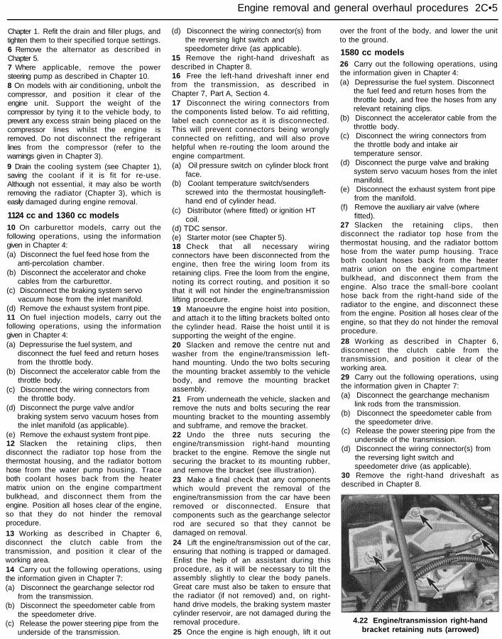
4.22 Engine/transmission right-handbracket retaining nuts (arrowed)

2C•6 Engine removal and general overhaul procedures
4.35a On 1761 cc models, disconnect thewiring connectors (arrowed) from the
throttle housing . . .
31 Free the left-hand driveshaft inner endfrom the transmission, as described inChapter 7, Part A, Section 4.32 Disconnect the wiring connectors fromthe components listed below. To aid refitting,label each connector as it is disconnected.This will prevent connectors being wronglyconnected on refitting, and will also provehelpful when re-routing the loom around theengine compartment.(a) Oil pressure switch, oil level sender
and/or oil temperature switch (asapplicable - see Chapter 5).
(b) Coolant temperature switch/sendersscrewed into the thermostat housing/left-hand end of cylinder head.
(c) Ignition HT coil.(d) TDC sensor.(e) Starter motor (see Chapter 5).33 Check that all necessary wiringconnectors have been disconnected from theengine, then free the wiring loom from all itsrelevant retaining clips. Free the loom fromthe engine, noting its correct routing, andposition it so that it will not hinder theengine/transmission lifting procedure.34 The engine and transmission can thenbe removed as described above in para-graphs 19 to 25.
1761 cc models
35 Carry out the following operations, usingthe information given in Chapter 4:
4.35b . . . and remove the auxiliary airvalve
(a) Depressurise the fuel system. Disconnectthe fuel feed and return hoses from thefuel rail, and free the hoses from anyrelevant retaining clips.
(b) Disconnect the accelerator cable from thethrottle housing.
(c) Disconnect the wiring connectors fromthe throttle housing and fuel injectors (seeillustration).
(d) Disconnect the purge valve and brakingsystem servo vacuum hoses from the inletmanifold.
(e) Disconnect the exhaust system front pipefrom the manifold.
(f) Remove the auxiliary air valve (seeillustration).
(g) Remove the ECU and its protectiveplastic box.
36 The engine and transmission can thenbe removed as described above in para-graphs 27 to 34.
1905 cc models37 Carry out the following operations, usingthe information given in Chapter 4:(a) Depressurise the fuel system. Disconnect
the fuel feed and return hoses from thefuel rail, and free the hoses from anyrelevant retaining clips.
(b) Disconnect the accelerator cable from thethrottle housing.
(c) Disconnect the wiring connectors from thethrottle potentiometer and fuel injectors.
4.41a Right-hand mounting curvedretaining plate retaining bolts (1), rubber
damper ( 2 ) . . .
4.41b . . . mounting bracket retainingnuts (3) and bolts (4) - 1998 cc models
(d) Disconnect the purge valve and/orbraking system servo vacuum hoses fromthe inlet manifold (as applicable).
(e) Disconnect the exhaust system front pipefrom the manifold.
(f) On models with a catalytic converter,remove the airflow meter.
38 The engine and transmission can thenbe removed as described above in para-graphs 27 to 34.
1998 cc 8-valve models39 Carry out the following operations, usingthe information given in Chapter 4:(a) Depressurise the fuel system. Disconnect
the fuel feed and return hoses from thefuel rail, and free the hoses from anyrelevant retaining clips.
(b) Disconnect the accelerator cable from thethrottle housing.
(c) Disconnect the wiring connectors fromthe throttle housing, knock sensor, andthe fuel injectors.
(d) Disconnect the purge valve and brakingsystem servo vacuum hoses from the inletmanifold.
(e) Disconnect the exhaust system front pipefrom the manifold.
(f) Remove the ECU and its protectiveplastic box.
40 The engine and transmission can thenbe removed as described above in para-graphs 27 to 34; note, however, that the engineright-hand mounting is dismantled as follows.41 Undo the two bolts securing the curvedmounting retaining plate to the body. Lift offthe plate, and withdraw the rubber damperfrom the top of the mounting bracket. Slackenand remove the two nuts and two boltssecuring the right-hand mounting bracket tothe engine. Remove the single nut securingthe bracket to the mounting rubber, and lift offthe bracket (see illustrations).
1998 cc 16-valve models42 Carry out the following operations, usingthe information given in Chapter 4:(a) Depressurise the fuel system. Disconnect
the fuel feed and return hoses from theirfuel rail unions, and free the hoses fromthe retaining clips on the cylinder headcover.
(b) Remove the inlet manifold.(c) Disconnect the wiring connectors from
the camshaft position sensor, knocksensor, and the fuel injectors.
(d) Disconnect the exhaust system front pipefrom the manifold.
(e) Remove the ECU and its protectiveplastic box.
43 Locate the ignition HT coil wiringconnector (on the left-hand end of the cylinderhead). Rotate the locking ring anti-clockwise,and disconnect the connector from the mainwiring loom.44 Disconnect the braking system servovacuum hose from its union just to the rear ofthe vacuum pump.
Engine removal and general overhaul procedures 2C•7
45 The engine and transmission can thenbe removed as described above in para-graphs 27 to 34; note, however, that theengine right-hand mounting is dismantled asfollows.46 Undo the two bolts securing the curvedmounting retaining plate to the body. Lift off theplate, and withdraw the rubber damper fromthe top of the mounting bracket. Slacken andremove the two nuts and two bolts securingthe right-hand mounting bracket to the engine.Remove the single nut securing the bracket tothe mounting rubber, and lift off the bracket.
Separation47 With the engine/transmission assemblyremoved, support the assembly on suitableblocks of wood, on a workbench (or failingthat, on a clean area of the workshop floor).48 Undo the retaining bolts, and remove theflywheel lower cover plate (where fitted) fromthe transmission.49 On models with a "pull-type" clutchrelease mechanism (see Chapter 6 for furtherinformation), tap out the retaining pin orunscrew the retaining bolt (as applicable), andremove the clutch release lever from the topof the release fork shaft. This is necessary toallow the fork shaft to rotate freely, so that itdisengages from the release bearing as thetransmission is pulled away from the engine.Make an alignment mark across the centre ofthe clutch release fork shaft, using a scriber,paint or similar, and mark its relative positionon the transmission housing (see Chapter 7,Part A, Section 7 for further information).
50 Slacken and remove the retaining bolts,and remove the starter motor from thetransmission.51 Ensure that both engine and transmissionare adequately supported, then slacken andremove the remaining bolts securing thetransmission housing to the engine. Note thecorrect fitted positions of each bolt (and therelevant brackets) as they are removed, to useas a reference on refitting.52 Carefully withdraw the transmission fromthe engine, ensuring that the weight of thetransmission is not allowed to hang on theinput shaft while it is engaged with the clutchfriction disc.53 If they are loose, remove the locatingdowels from the engine or transmission, andkeep them in a safe place.54 On models with a "pull-type" clutch, makea second alignment mark on the transmissionhousing, marking the relative position of therelease fork mark after removal. This shouldindicate the angle at which the release fork ispositioned. The mark can then be used toposition the release fork prior to installation, toensure that the fork correctly engages withthe clutch release bearing as the transmissionis installed.
Refitting55 If the engine and transmission have beenseparated, perform the operations described
below in paragraphs 56 to 64. If not, proceedas described from paragraph 65 onwards.56 Apply a smear of high-melting-pointgrease to the splines of the transmission inputshaft. Do not apply too much, otherwise thereis a possibility of the grease contaminating theclutch friction plate.57 Ensure that the locating dowels arecorrectly positioned in the engine ortransmission.58 On models with a "pull-type" clutch,position the clutch release bearing so that its"HAUT" mark is at the top, and the "BAS"mark is at the bottom. Align the release forkshaft mark with the second mark made on thetransmission housing. This will ensure that therelease fork and bearing will engage correctlyas the transmission is refitted to the engine.59 Carefully offer the transmission to theengine, until the locating dowels are engaged.Ensure that the weight of the transmission isnot allowed to hang on the input shaft as it isengaged with the clutch friction disc.60 On models with a "pull-type" clutch, withthe transmission fully engaged with theengine, check that the release fork andbearing are correctly engaged. If the releasefork and bearing are correctly engaged, themark on the release fork should be alignedwith the original mark made on thetransmission housing (see Chapter 7, Part A,Section 7 for further information).61 Refit the transmission housing-to-enginebolts, ensuring that all the necessary bracketsare correctly positioned, and tighten them tothe specified torque setting.62 Refit the starter motor, and securelytighten its retaining bolts.63 On models with a "pull-type" clutchrelease mechanism, refit the clutch releaselever to the top of the release fork shaft,securing it in position with its retaining pin orbolt (as applicable).64 Where necessary, refit the lower flywheelcover plate to the transmission, and securelytighten its retaining bolts.65 Reconnect the hoist and lifting tackle tothe engine lifting brackets. With the aid of anassistant, lift the assembly over the enginecompartment.66 The assembly should be tilted asnecessary to clear the surroundingcomponents, as during removal; lower theassembly into position in the enginecompartment, manipulating the hoist andlifting tackle as necessary.67 With the engine/transmission in position,refit the right-hand engine/transmissionmounting bracket, tightening its retaining nutsand bolts (as applicable) by hand only at thisstage.68 Refit the left-hand engine/transmissionmounting bracket assembly to the vehicle,and tighten its retaining bolts to the specifiedtorque. Refit the centre nut and washer to theleft-hand mounting, tightening it to thespecified torque setting. Tighten the right-hand mounting bracket retaining nuts and
bolts (as applicable) to their specified torquesetting.69 On 1998 cc 8-valve and 16-valve models,refit the rubber damper to the top of the right-hand mounting bracket. Refit the curvedretaining plate, and tighten its retaining boltsto the specified torque.70 On all models, from underneath thevehicle, refit the rear mounting bracket, andtighten both its retaining bolts to the specifiedtorque. The hoist can then be detached fromthe engine and removed.71 The remainder of the refitting procedure isa direct reversal of the removal sequence,noting the following points:(a) Ensure that the wiring loom is correctly
routed and retained by all the relevantretaining clips; all connectors should becorrectly and securely reconnected.
(b) Prior to refitting the driveshafts to thetransmission, renew the driveshaft oilseals as described in Chapter 7.
(c) Ensure that all coolant hoses are correctlyreconnected, and securely retained bytheir retaining clips.
(d) Adjust the clutch cable as described inChapter 6.
(e) Adjust the choke cable and/or acceleratorcable (as applicable) as described inChapter 4.
(f) Refill the engine and transmission withcorrect quantity and type of lubricant, asdescribed in Chapter 1.
(g) Refill the cooling system as described inChapter 1.
RemovalNote: The engine can be removed from thecar only as a complete unit with thetransmission; the two are then separated foroverhaul.1 Carry out the operations described inparagraphs 1 to 9 of Section 4.
1580 cc models2 Carry out the following operations, usingthe information given in Chapter 4:(a) Depressurise the fuel system. Disconnect
the fuel feed and return hoses from thethrottle body, and free the hoses from anyrelevant retaining clips.
(b) Disconnect the accelerator cable from thethrottle body.
(c) Disconnect the wiring connectors fromthe throttle body and intake airtemperature sensor.
(d) Disconnect the purge valve and brakingsystem servo vacuum hoses from the inletmanifold.
(e) Disconnect the exhaust system front pipefrom the manifold.
(f) Remove the auxiliary air valve (where fitted).
5 Engine and automatictransmission - removal,separation and refitting

2C•8 Engine removal and general overhaul procedures
1761 cc models3 Carry out the following operations, usingthe information given in Chapter 4:(a) Depressurise the fuel system. Disconnect
the fuel feed and return hoses from thefuel rail, and free the hoses from anyrelevant retaining clips.
(b) Disconnect the accelerator cable from thethrottle housing.
(c). Disconnect the wiring connectors fromthe throttle housing and fuel injectors.
(d) Disconnect the purge valve and brakingsystem servo vacuum hoses from the inletmanifold.
(e) Disconnect the exhaust system front pipefrom the manifold.
(f) Remove the auxiliary air valve.(g) Remove the ECU and its protective
plastic box.
1905 cc models4 Carry out the following operations, usingthe information given in Chapter 4:(a) Depressurise the fuel system. Disconnect
the fuel feed and return hoses from thefuel rail, and free the hoses from anyrelevant retaining clips.
(b) Disconnect the accelerator cable from thethrottle housing.
(c) Disconnect the wiring connectors fromthe throttle potentiometer and fuelinjectors.
(d) Disconnect the purge valve and/orbraking system servo vacuum hoses fromthe inlet manifold (as applicable).
(e) Disconnect the exhaust system front pipefrom the manifold.
(f) On models with a catalytic converter,remove the airflow meter.
All models5 Slacken the retaining clips, then disconnectthe radiator top hose from the thermostathousing, and the radiator bottom hose fromthe water pump housing. Trace both coolanthoses back from the heater matrix union onthe engine compartment bulkhead, anddisconnect them from the engine. Also tracethe small-bore coolant hoses back from theleft-hand right-hand side of the radiator to theengine/transmission, and disconnect thesefrom the engine and transmission fluid cooler.Position all hoses clear of the engine, so thatthey do not hinder the removal procedure.6 Carry out the following operations, usingthe information given in Chapter 7:(a) Remove the transmission dipstick tube.(b) Disconnect the wiring from the starter
inhibitor/reversing light switch and thespeedometer drive housing. Release theearth strapfs) from the top of thetransmission housing.
(c) Disconnect the selector cable.(d) Release the power steering pipe from the
underside of the transmission.(e) Disconnect the speedometer cable.7 Remove the right-hand driveshaft asdescribed in Chapter 8.
8 Free the left-hand driveshaft inner end fromthe transmission, as described in Chapter 7,Part A, Section 4.9 Disconnect the wiring connectors from thecomponents listed below. To aid refitting,label each connector as it is disconnected.This will prevent connectors being wronglyconnected on refitting, and will also provehelpful when re-routing the loom around theengine compartment.(a) Oil pressure switch, oil level sender
and/or oil temperature switch (as .applicable - see Chapter 5).
(b) Coolant temperature switch/sendersscrewed into the thermostat housing/left-hand end of cylinder head.
(c) Ignition HT coil.(d) TDC sensor.(e) Starter motor (see Chapter 5).10 Check that all necessary wiringconnectors have been disconnected from theengine, then free the wiring loom from itsretaining clips. Free the loom from the engine,noting its correct routing, and position it sothat it will not hinder the engine/transmissionlifting procedure.11 Manoeuvre the engine hoist into position,and attach it to the lifting brackets bolted ontothe cylinder head. Raise the hoist until it issupporting the weight of the engine.12 Slacken and remove the centre nut andwasher from the engine/transmission left-hand mounting. Undo the two bolts securingthe mounting bracket assembly to the vehiclebody, and remove the mounting bracketassembly.13 From underneath the vehicle, slacken andremove the nuts and bolts securing the rearmounting bracket to the mounting assemblyand subframe, and remove the bracket.14 Undo the three nuts securing theengine/transmission right-hand mountingbracket to the engine. Remove the single nutsecuring the bracket to its mounting rubber,and remove the bracket.15 Make a final check that all componentsthat will prevent the removal of theengine/transmission from the car have beenremoved or disconnected. Ensure that allcomponents are secured so that they cannotbe damaged on removal.16 Lift the engine/transmission out of the car,ensuring that nothing is trapped or damaged.Enlist the help of an assistant during thisprocedure, as it will be necessary to tilt theassembly slightly to clear the body panels.Great care must also be taken to ensure thatthe radiator (if not removed) and, on right-hand drive models, the braking system mastercylinder reservoir, are not damaged during theremoval procedure.17 Once the engine is high enough, lift it outover the front of the body, and lower the unitto the ground.
Separation18 With the engine/transmission assemblyremoved, support the assembly on suitable
blocks of wood, on a workbench (or failingthat, on a clean area of the workshop floor).19 Detach the kickdown cable from thethrottle cam. Work back along the cable,freeing it from any retaining clips, and notingits correct routing.20 Undo the retaining bolts and remove thedriveplate lower cover plate from thetransmission, to gain access to the torqueconverter retaining bolts. Slacken and removethe visible bolt. Rotate the crankshaft using asocket and extension bar on the pulley bolt,and undo the remaining bolts securing thetorque converter to the driveplate as theybecome accessible. There are three bolts intotal.21 Slacken and remove the retaining bolts,and remove the starter motor from thetransmission.22 To ensure that the torque converter doesnot fall out as the transmission is removed,secure it in position using a length of metalstrip bolted to one of the starter motor boltholes.23 Ensure that both the engine andtransmission are adequately supported, thenslacken and remove the remaining boltssecuring the transmission housing to theengine. Note the correct fitted positions ofeach bolt (and any relevant brackets) as theyare removed, to use as a reference onrefitting.24 Carefully withdraw the transmission fromthe engine. If the locating dowels are a loosefit in the engine/transmission, remove themand keep them in a safe place.
Refitting25 If the engine and transmission have beenseparated, perform the operations describedbelow in paragraphs 26 to 32. If not, proceedas described from paragraph 33 onwards.26 Ensure that the bush fitted to the centre ofthe crankshaft is in good condition. Apply alittle Molykote G1 grease (available from yourCitroen dealer) to the torque convertercentring pin. Do not apply too much,otherwise there is a possibility of the greasecontaminating the torque converter.27 Ensure that the locating dowels arecorrectly positioned in the engine ortransmission.28 Carefully offer the transmission to theengine, until the locating dowels are engaged.29 Refit the transmission housing-to-enginebolts, ensuring that all the necessary bracketsare correctly positioned, and tighten them tothe specified torque setting.30 Remove the torque converter retainingstrap installed prior to removal. Align thetorque converter threaded holes with theretaining plate, and refit the three retainingbolts.31 Tighten the torque converter retainingbolts to the specified torque setting, then refitthe driveplate lower cover.32 Refit the starter motor, and securelytighten its retaining bolts.

Engine removal and general overhaul procedures 2C•9
33 Reconnect the hoist and lifting tackle tothe engine lifting brackets. With the aid of anassistant, lift the assembly over the enginecompartment.34 The assembly should be tilted asnecessary to clear surrounding components,as during removal; lower the assembly intoposition in the engine compartment,manipulating the hoist and lifting tackle asnecessary.35 With the engine/transmission in position,refit the engine/transmission right-handmounting bracket, tightening its retaining nutsby hand only at this stage.36 Refit the engine/transmission left-handmounting bracket assembly to the vehicle,and tighten its retaining bolts to the specifiedtorque. Refit the centre nut and washer to theleft-hand mounting, tightening it to thespecified torque setting. Tighten the right-hand mounting bracket retaining nuts to theirspecified torque setting.37 From underneath the vehicle, refit the rearmounting bracket, and tighten both itsretaining bolts to the specified torque. Thehoist can then be detached from the engineand removed.38 The remainder of the refitting procedure isa reversal of the removal sequence, noting thefollowing points:(a) Ensure that the wiring loom is correctly
routed, and retained by all the relevantretaining clips; all connectors should becorrectly and securely reconnected.
(b) Prior to refitting the driveshafts to thetransmission, renew the driveshaft oilseals as described in Chapter 7.
(c) Ensure that all coolant hoses are correctlyreconnected, and securely retained bytheir retaining clips.
(d) Adjust the selector cable and kickdowncable as described in Chapter 7, Part B.
(ej Adjust the accelerator cable as describedin Chapter 4.
(f) Refill the engine and transmission withcorrect quantity and type of lubricant, asdescribed in Chapter 1.
(g) Refill the cooling system as described inChapter 1.
1 It is much easier to dismantle and work onthe engine if it is mounted on a portableengine stand. These stands can often be hiredfrom a tool hire shop. Before the engine ismounted on a stand, the flywheel/driveplateshould be removed, so that the stand boltscan be tightened into the end of the cylinderblock/crankcase.2 If a stand is not available, it is possible todismantle the engine with it blocked up on asturdy workbench, or on the floor. Be extra-careful not to tip or drop the engine whenworking without a stand.3 If you are going to obtain a reconditioned
engine, all the external components must beremoved first, to be transferred to thereplacement engine (just as they will if you aredoing a complete engine overhaul yourself).These components include the following:(a) Alternator mounting brackets (Chapter 5).(b) Power steering pump and air conditioning
compressor brackets (where fitted)(Chapters 3 and 10).
(c) Distributor, HT leads and spark plugs (asapplicable) (Chapters 1 and 5).
(d) Thermostat and housing, and coolantoutlet chamber/elbow (Chapter 3).
(e) Dipstick tube.(f) Carburettor/fuel injection system
components (Chapter 4).(g) All electrical switches and sensors.(h) Inlet and exhaust manifolds (Chapter 4).(i) ACAV assembly - 1998 cc 16-valve
engines only (Chapter 4).(j) Oil filter (Chapter 1).(k) Fuel pump - carburettor engines only
(Chapter 4).(I) Engine mountings (Part A or B of this
Chapter),(m) Flywheel/driveplate (Part A or B of this
Chapter).Note: When removing the external
components from the engine, pay closeattention to details that may be helpful orimportant during refitting. Note the fittedposition of gaskets, seals, spacers, pins,washers, bolts, and other small items.4 If you are obtaining a "short" engine (whichconsists of the engine cylinder block/crank-case, crankshaft, pistons and connecting rodsall assembled), then the cylinder head, sump,oil pump, and timing belt will have to beremoved also.5 If you are planning a complete overhaul, theengine can be dismantled, and the internalcomponents removed, in the order givenbelow, referring to Part A or B of this Chapterunless otherwise stated.(a) Inlet and exhaust manifolds (Chapter 4).(b) ACAV assembly-1998 cc 16-valve
engines only (Chapter 4).(c) Timing belt, sprockets and tensioner(s).(d) Cylinder head.(e) Flywheel.(f) Sump.
(g) Oil pump.(h) Piston/connecting rod assemblies
(Section 10).(i) Crankshaft (Section 11).6 Before beginning the dismantling andoverhaul procedures, make sure that you haveall of the correct tools necessary. Refer to"Tools and working facilities" at the end of thismanual for further information.
7 Cylinder head - dismantling
Note: New and reconditioned cylinder headsare available from the manufacturer, and fromengine overhaul specialists. Be aware that somespecialist tools are required for the dismantlingand inspection procedures, and newcomponents may not be readily available. It maytherefore be more practical and economical forthe home mechanic to purchase areconditioned head, rather than dismantle,inspect and recondition the original head.1 Remove the cylinder head as described inPart A or B of this Chapter (as applicable).2 Remove the camshaft(s), followers andshims (as applicable) as described in Part A orB of this Chapter.3 Using a valve spring compressor, compresseach valve spring in turn until the split colletscan be removed. Release the compressor,and lift off the spring retainer, spring andspring seat. Using a pair of pliers, carefullyextract the valve stem seal from the top of theguide (see illustrations).
7.3a Compress the valve spring using aspring compressor . . .
7.3b . . . then extract the collets andrelease the spring compressor 7.3c Remove the spring retainer .
6 Engine overhaul -dismantling sequence

2C•10 Engine removal and general overhaul procedures
7.3d . . . followed by the valve spring . . .
4 If, when the valve spring compressor isscrewed down, the spring retainer refuses tofree and expose the split collets, gently tapthe top of the tool, directly over the retainer,with a light hammer. This will free the retainer.5 Withdraw the valve through the combustionchamber.6 It is essential that each valve is storedtogether with its collets, retainer, spring, andspring seat. The valves should also be kept intheir correct sequence, unless they are sobadly worn that they are to be renewed. Notethat No 1 valve is nearest to the transmission(flywheel/driveplate) end of the engine.
7.3e . . . and the spring seat
If the valve and its associatedcomponents are going to be usedagain, place each valve assembly in alabelled polythene bag or similar smallcontainer.
3 Scrape away the carbon from thecombustion chambers and ports, then washthe cylinder head thoroughly with paraffin or asuitable solvent.4 Scrape off any heavy carbon deposits thatmay have formed on the valves, then use apower-operated wire brush to removedeposits from the valve heads and stems.
InspectionNote: Be sure to perform all the followinginspection procedures before concluding thatthe services of a machine shop or engineoverhaul specialist are required. Make a list ofall items that require attention.
Cylinder head5 Inspect the head very carefully for cracks,evidence of coolant leakage, and otherdamage. If cracks are found, a new cylinderhead should be obtained.6 Use a straight-edge and feeler gauge bladeto check that the cylinder head surface is notdistorted (see illustration). If it is, it may bepossible to have it machined, provided thatthe cylinder head is not reduced to less thanthe specified height. The cylinder head heightis measured from the centre of the cylinderhead camshaft bore to the cylinder headgasket face. Note: Cylinder heads that havehad their gasket surface refaced by Citroenwill be stamped with an "R" somewhere onthe left-hand end of the cylinder head, around
8 Cylinder head and valves -cleaning and inspection
1 Thorough cleaning of the cylinder head andvalve components, followed by a detailedinspection, will enable you to decide howmuch valve service work must be carried outduring the engine overhaul. Note: If theengine has been severely overheated, it is bestto assume that the cylinder head is warped -check carefully for signs of this.
Cleaning2 Scrape away all traces of old gasketmaterial and sealing compound from thecylinder head.
7.3f Remove the valve stem oil seal usinga pair of pliers
the thermostat housing area. These headshave had 0.2 mm machined off the gasketface. When fitting to the engine, a slightlythicker head gasket should be used (seePart A or B for further information).7 Examine the valve seats in each of thecombustion chambers. If they are severelypitted, cracked, or burned, they will need tobe renewed or re-cut by an engine overhaulspecialist. If they are only slightly pitted, thiscan be removed by grinding-in the valveheads and seats with fine valve-grindingcompound, as described below. Note: It isnot possible to renew the valve seats on the1998 cc 16-valve engine.8 Check the valve guides for wear byinserting the relevant valve, and checking forside-to-side motion of the valve. A very smallamount of movement is acceptable. If themovement seems excessive, remove thevalve. Measure the valve stem diameter (seebelow), and renew the valve if it is worn. If thevalve stem is not worn, the wear must be inthe valve guide, and the guide must berenewed. The renewal of valve guides is bestcarried out by a Citroen dealer or engineoverhaul specialist, who will have thenecessary tools available. Where no valvestem diameter is specified, seek the advice ofa Citroen dealer on the best course of action.9 If the valve seats are to be re-cut or re-ground, this must be done only after theguides have been renewed.
8.6 Checking the cylinder head gasketsurface for distortion
8.11 Measuring a valve stem diameter
Engine removal and general overhaul procedures 2C•11
8.14 Grinding-in a valve
Valves
10 Examine the head of each valve forpitting, burning, cracks, and general wear.Check the valve stem for scoring and wearridges. Rotate the valve, and check for anyobvious indication that it is bent. Look for pitsand excessive wear on the tip of each valvestem. Renew any valve that shows any suchsigns of wear or damage.11 If the valve appears satisfactory at thisstage, measure the valve stem diameter atseveral points using a micrometer (seeillustration). Any significant difference in thereadings obtained indicates wear of the valvestem. Should any of these conditions beapparent, the valve(s) must be renewed.12 If the valves are in satisfactory condition,they should be ground (lapped) into theirrespective seats, to ensure a smooth, gas-tight seal. If the seat is only lightly pitted, or ifit has been re-cut, fine grinding compoundonly should be used to produce the requiredfinish. Coarse valve-grinding compoundshould not be used unless a seat is badlyburned or deeply pitted. If this is the case, thecylinder head and valves should be inspectedby an expert, to decide whether seat re-cutting, or even the renewal of the valve orseat insert (where possible) is required.13 Valve grinding is carried out as follows.Place the cylinder head upside-down on abench.14 Smear a trace of (the appropriate gradeof) valve-grinding compound on the seat face,and press a suction grinding tool onto thevalve head. With a semi-rotary action, grindthe valve head to its seat, lifting the valveoccasionally to redistribute the grindingcompound (see illustration).
15 If coarse grinding compound is beingused, work only until a dull, matt even surfaceis produced on both the valve seat and thevalve, then wipe off the used compound, andrepeat the process with fine compound. Whena smooth unbroken ring of light grey matt
9.1 Lubricate the valve stems prior torefitting
finish is produced on both the valve and seat,the grinding operation is complete. Do notgrind-in the valves any further than absolutelynecessary, or the seat will be prematurelysunk into the cylinder head.16 To check that the seat has not been over-ground, measure the valve stem installedheight, as described in paragraph 7 above.17 When all the valves have been ground-in,carefully wash off all traces of grindingcompound using paraffin or a suitable solvent,before reassembling the cylinder head.
Valve components18 Examine the valve springs for signs ofdamage and discoloration. No minimum freelength is specified by Citroen, so the only wayof judging valve spring wear is by comparisonwith a new component.19 Stand each spring on a flat surface, andcheck it for squareness. If any of the springsare damaged, distorted or have lost theirtension, obtain a complete new set of springs.It is normal to renew the valve springs as amatter of course if a major overhaul is beingcarried out.20 Renew the valve stem oil seals regardlessof their apparent condition.
1 Lubricate the stems of the valves, andinsert them into their original locations (seeillustration). If new valves are being fitted,insert them into the locations to which theyhave been ground.2 Refit the spring seat then, working on thefirst valve, dip the new valve stem seal in freshengine oil. Carefully locate it over the valve andonto the guide. Take care not to damage theseal as it is passed over the valve stem. Use asuitable socket or metal tube to press the sealfirmly onto the guide (see illustration).3 Locate the valve spring on top of its seat,then refit the spring retainer.4 Compress the valve spring, and locate thesplit collets in the recess in the valve stem.Use a little grease to hold the collets in place.Release the compressor, then repeat theprocedure on the remaining valves.
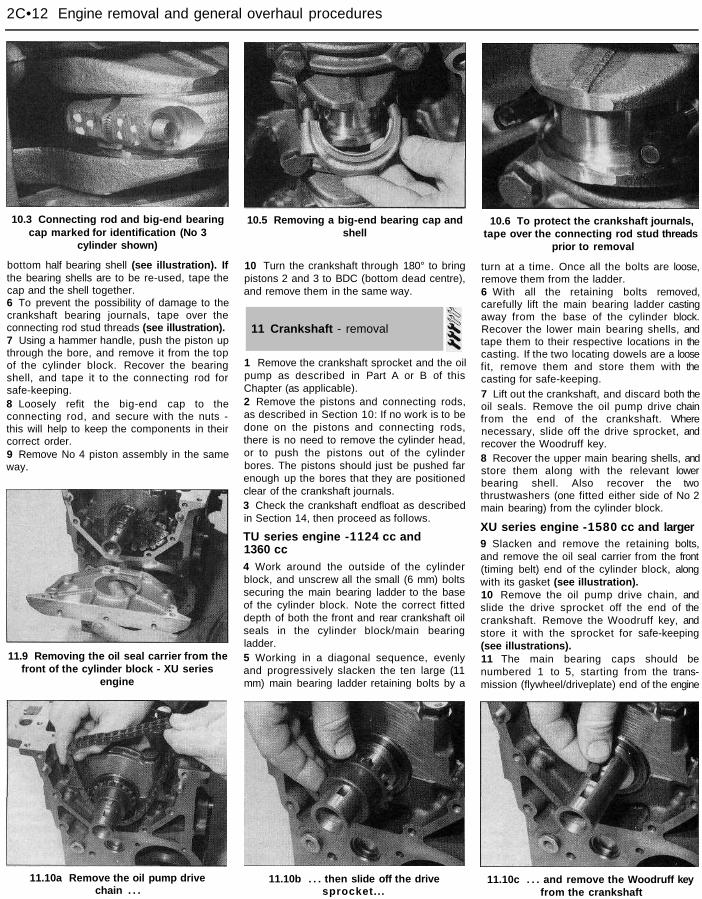
9.2 Fitting a valve stem oil seal using asocket
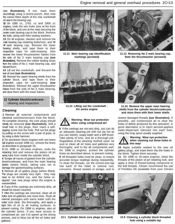
9.6 Refitting a cam follower -1905 ccmodel. Note the shim (arrowed)
5 With all the valves installed, place thecylinder head flat on the bench and, using ahammer and interposed block of wood, tapthe end of each valve stem to settle thecomponents.6 Refit the shims (where fitted), cam followersand camshaft(s) as described in Part A or B(as applicable) (see illustration).
10 Piston/connecting rodassembly - removal
1 Remove the cylinder head, sump and oilpump as described in Part A or B of thisChapter (as applicable)2 If there is a pronounced wear ridge at thetop of any bore, it may be necessary toremove it with a scraper or ridge reamer, toavoid piston damage during removal. Such aridge indicates excessive wear of the cylinderbore.3 Using a hammer and centre-punch, paint orsimilar, mark each connecting rod big-endbearing cap with its respective cylindernumber on the flat machined surfaceprovided; if the engine has been dismantledbefore, note carefully any identifying marksmade previously (see illustration). Note thatNo 1 cylinder is at the transmission(flywheel/driveplate) end of the engine.4 Turn the crankshaft to bring pistons 1 and 4to BDC (bottom dead centre).5 Unscrew the nuts from No 1 piston big-endbearing cap. Take off the cap, and recover the
9 Cylinder head - reassembly
A light spring placed underthe valve head will greatlyease the grinding operation.
2C•12 Engine removal and general overhaul procedures
10.3 Connecting rod and big-end bearingcap marked for identification (No 3
cylinder shown)
bottom half bearing shell (see illustration). Ifthe bearing shells are to be re-used, tape thecap and the shell together.6 To prevent the possibility of damage to thecrankshaft bearing journals, tape over theconnecting rod stud threads (see illustration).7 Using a hammer handle, push the piston upthrough the bore, and remove it from the topof the cylinder block. Recover the bearingshell, and tape it to the connecting rod forsafe-keeping.8 Loosely refit the big-end cap to theconnecting rod, and secure with the nuts -this will help to keep the components in theircorrect order.9 Remove No 4 piston assembly in the sameway.
10.5 Removing a big-end bearing cap andshell
10 Turn the crankshaft through 180° to bringpistons 2 and 3 to BDC (bottom dead centre),and remove them in the same way.
11 Crankshaft - removal
11.9 Removing the oil seal carrier from thefront of the cylinder block - XU series
engine
1 Remove the crankshaft sprocket and the oilpump as described in Part A or B of thisChapter (as applicable).2 Remove the pistons and connecting rods,as described in Section 10: If no work is to bedone on the pistons and connecting rods,there is no need to remove the cylinder head,or to push the pistons out of the cylinderbores. The pistons should just be pushed farenough up the bores that they are positionedclear of the crankshaft journals.3 Check the crankshaft endfloat as describedin Section 14, then proceed as follows.
TU series engine -1124 cc and1360 cc4 Work around the outside of the cylinderblock, and unscrew all the small (6 mm) boltssecuring the main bearing ladder to the baseof the cylinder block. Note the correct fitteddepth of both the front and rear crankshaft oilseals in the cylinder block/main bearingladder.5 Working in a diagonal sequence, evenlyand progressively slacken the ten large (11mm) main bearing ladder retaining bolts by a
10.6 To protect the crankshaft journals,tape over the connecting rod stud threads
prior to removal
turn at a time. Once all the bolts are loose,remove them from the ladder.6 With all the retaining bolts removed,carefully lift the main bearing ladder castingaway from the base of the cylinder block.Recover the lower main bearing shells, andtape them to their respective locations in thecasting. If the two locating dowels are a loosefit, remove them and store them with thecasting for safe-keeping.7 Lift out the crankshaft, and discard both theoil seals. Remove the oil pump drive chainfrom the end of the crankshaft. Wherenecessary, slide off the drive sprocket, andrecover the Woodruff key.8 Recover the upper main bearing shells, andstore them along with the relevant lowerbearing shell. Also recover the twothrustwashers (one fitted either side of No 2main bearing) from the cylinder block.
XU series engine -1580 cc and larger9 Slacken and remove the retaining bolts,and remove the oil seal carrier from the front(timing belt) end of the cylinder block, alongwith its gasket (see illustration).10 Remove the oil pump drive chain, andslide the drive sprocket off the end of thecrankshaft. Remove the Woodruff key, andstore it with the sprocket for safe-keeping(see illustrations).11 The main bearing caps should benumbered 1 to 5, starting from the trans-mission (flywheel/driveplate) end of the engine
11.10a Remove the oil pump drivechain . . .
11.10b . . . then slide off the drivesprocket...
11.10c . . . and remove the Woodruff keyfrom the crankshaft
Engine removal and general overhaul procedures 2C•13
(see illustration). If not, mark themaccordingly using a centre-punch. Also notethe correct fitted depth of the rear crankshaftoil seal in the bearing cap.12 On 1580 cc, 1761 cc and 1905 ccengines, undo the two bolts (one at the frontof the block, and one at the rear) securing thecentre main bearing cap to the block. Removethe bolts, along with their sealing washers.13 On all engines, slacken and remove themain bearing cap retaining bolts/nuts, and liftoff each bearing cap. Recover the lowerbearing shells, and tape them to theirrespective caps for safe-keeping. Alsorecover the lower thrustwasher halves fromthe side of No 2 main bearing cap (seeillustration). Remove the rubber sealing stripsfrom the sides of No 1 main bearing cap, anddiscard them.14 Lift out the crankshaft, and discard therear oil seal (see illustration).15 Recover the upper bearing shells from thecylinder block, and tape them to theirrespective caps for safe-keeping (seeillustration). Remove the upper thrustwasherhalves from the side of No 2 main bearing,and store them with the lower halves.
Cleaning1 Remove all external components andelectrical switches/sensors from the block.For complete cleaning, the core plugs shouldideally be removed (see illustration). Drill asmall hole in the plugs, then insert a self-tapping screw into the hole. Pull out the plugsby pulling on the screw with a pair of grips, orby using a slide hammer.2 On aluminium block engines with wet liners(all engines except 1998 cc), remove the linersas described in paragraph 16.3 On 1998 cc 16-valve engines, undo theretaining bolt and remove the piston oil jetspray tube from inside the cylinder block.4 Scrape all traces of gasket from the cylinderblock/crankcase, and from the main bearingladder (where fitted), taking care not todamage the gasket/sealing surfaces.5 Remove all oil gallery plugs (where fitted).The plugs are usually very tight - they mayhave to be drilled out, and the holes re-tapped. Use new plugs when the engine isreassembled.6 If any of the castings are extremely dirty, allshould be steam-cleaned.7 After the castings are returned, clean all oilholes and oil galleries one more time. Flush allinternal passages with warm water until thewater runs clear. Dry thoroughly, and apply alight film of oil to all mating surfaces, toprevent rusting. On 1998 cc engines, also oilthe cylinder bores. If you have access tocompressed air, use it to speed up the dryingprocess, and to blow out all the oil holes andgalleries.
11.11 Main bearing cap identificationmarkings (arrowed)
11.13 Removing No 2 main bearing cap.Note the thrustwasher (arrowed)
11.14 Lifting out the crankshaft -XU series engine
Warning: Wear eye protectionwhen using compressed air!
8 If the castings are not very dirty, you can doan adequate cleaning job with hot (as hot asyou can stand!), soapy water and a stiff brush.Take plenty of time, and do a thorough job.Regardless of the cleaning method used, besure to clean all oil holes and galleries verythoroughly, and to dry all components well.On 1998 cc engines, protect the cylinderbores as described above, to prevent rusting.9 All threaded holes must be clean, to ensureaccurate torque readings during reassembly.To clean the threads, run the correct-size tapinto each of the holes to remove rust,corrosion, thread sealant or sludge, and to
11.15 Remove the upper main bearingshells from the cylinder block/crankcase,
and store them with their lower shells
restore damaged threads (see illustration). Ifpossible, use compressed air to clear theholes of debris produced by this operation. Agood alternative is to inject aerosol-appliedwater-dispersant lubricant into each hole,using the long spout usually supplied.
Warning: Wear eye protectionwhen cleaning out these holes inthis way!
10 Apply suitable sealant to the new oilgallery plugs, and insert them into the holes inthe block. Tighten them securely.11 On 1998 cc 16-valve engines, clean thethreads of the piston oil jet retaining bolt, andapply a drop of thread-locking compound tothe bolt threads. Citroen recommend the useof Frenbloc E6 (available from your Citroen
12.1 Cylinder block core plugs (arrowed) 12.9 Cleaning a cylinder block threadedhole using a suitable tap
12 Cylinder block/crankcase -cleaning and inspection

2C•14 Engine removal and general overhaul procedures
12.16a On aluminium block engines,remove each liner . . .
dealer); in the absence of this, any suitablegood-quality locking compound may be used.Refit the piston oil jet spray tube to thecylinder block, and tighten its retaining bolt tothe specified torque setting.12 If the engine is not going to bereassembled right away, cover it with a largeplastic bag to keep it clean; protect all matingsurfaces and the cylinder bores as describedabove, to prevent rusting.
InspectionCast-iron cylinder block -1998 ccengines13 Visually check the castings for cracks andcorrosion. Look for stripped threads in thethreaded holes. If there has been any historyof internal water leakage, it may be worthwhilehaving an engine overhaul specialist checkthe cylinder block/crankcase with specialequipment. If defects are found, have themrepaired if possible, or renew the assembly.14 Check the each cylinder bore for scuffingand scoring. Check for signs of a wear ridgeat the top of the cylinder, indicating that thebore is excessively worn.15 Since Citroen do not state any specificwear limits for the cylinder bores or pistons, itis not possible to assess the amount of wearby direct measurement. If there is any doubtabout the condition of the cylinder bores,seek the advice of a Citroen dealer or enginereconditioning specialist. At the time ofwriting, oversize pistons were not available,so therefore it is not advisable to rebore thecylinders. Consult your Citroen dealer forpiston availability; if oversize pistons are notavailable, and the bores are worn, renewal ofthe block seems to be the only option.
Aluminium cylinder block with wetliners - all other engines16 Remove the liner clamps (where used),then use a hard wood drift to tap out eachliner from inside the cylinder block. When allthe liners are released, tip the cylinderblock/crankcase on its side and remove eachliner from the top of the block. As each liner isremoved, stick masking tape on its left-hand(transmission side) face, and write the cylindernumber on the tape. No 1 cylinder is at the
12.16b . . . and recover the bottom O-ringseal (arrowed)
transmission (flywheel/driveplate) end of theengine. Remove the O-ring from the base ofeach liner, and discard (see illustrations).17 Check each cylinder liner for scuffing andscoring. Check for signs of a wear ridge at thetop of the liner, indicating that the bore isexcessively worn.18 If the necessary measuring equipment isavailable, measure the bore diameter of eachcylinder liner at the top (just under the wearridge), centre, and bottom of the cylinderbore, parallel to the crankshaft axis.19 Next, measure the bore diameter at thesame three locations, at right-angles to thecrankshaft axis. Compare the results with thefigures given in the Specifications.20 Repeat the procedure for the remainingcylinder liners.21 If the liner wear exceeds the permittedtolerances at any point, or if the cylinder linerwalls are badly scored or scuffed, thenrenewal of the relevant liner assembly will benecessary. If there is any doubt about thecondition of the cylinder bores, seek theadvice of a Citroen dealer or enginereconditioning specialist.22 If renewal is necessary, new liners,complete with pistons and piston rings, canbe purchased from a Citroen dealer. Note thatit is not possible to buy liners individually -they are supplied only as a matched assemblycomplete with piston and rings.23 To allow for manufacturing tolerances,pistons and liners are separated into threesize groups. The size group of each piston isindicated by a letter (A, B or C) stamped ontoits crown, and the size group of each liner isindicated by a series of 1 to 3 notches on theupper lip of the liner; a single notch for groupA, two notches for group B, and three notchesfor group C. Ensure that each piston and itsrespective liner are both of the same sizegroup. It is permissible to have different sizegroup piston and liner assemblies fitted to thesame engine, but never fit a piston of one sizegroup to a liner in a different group.
24 Prior to installing the liners, thoroughlyclean the liner mating surfaces in the cylinderblock, and use fine abrasive paper to polishaway any burrs or sharp edges which mightdamage the liner O-rings. Clean the liners and
13.2 Removing a piston ring with the aid ofa feeler gauge
wipe dry, then fit a new O-ring to the base ofeach liner. To aid installation, apply a smear ofoil to each O-ring and to the base of the liner.25 If the original liners are being refitted, usethe marks made on removal to ensure thateach is refitted the correct way round, and isinserted into its original bore. Insert each linerinto the cylinder block, taking care not todamage the O-ring, and press it home as faras possible by hand. Using a hammer and ablock of wood, tap each liner lightly but fullyonto its locating shoulder. Wipe clean, thenlightly oil, all exposed liner surfaces, toprevent rusting.26 With all four liners correctly installed, usea dial gauge (or a straight-edge and feelerblade) to check that the protrusion of eachliner above the upper surface of the cylinderblock is within the limits given in theSpecifications. The maximum differencebetween any two liners must not beexceeded.27 If new liners are being fitted, it ispermissible to interchange them to bring thedifference in protrusion within limits.Remember to keep each piston with itsrespective liner.28 If liner protrusion cannot be broughtwithin limits, seek the advice of a Citroendealer or engine reconditioning specialistbefore proceeding with the engine rebuild.
1 Before the inspection process can begin,the piston/connecting rod assemblies mustbe cleaned, and the original piston ringsremoved from the pistons.2 Carefully expand the old rings over the topof the pistons. The use of two or three oldfeeler blades will be helpful in preventing therings dropping into empty grooves (seeillustration). Be careful not to scratch thepiston with the ends of the ring. The rings arebrittle, and will snap if they are spread too far.They're also very sharp - protect your handsand fingers. Note that the third ringincorporates an expander. Always remove therings from the top of the piston. Keep each set
13 Piston/connecting rodassembly - inspection
Engine removal and general overhaul procedures 2C•15
13.15a On 1998 cc 16-valve models, priseout the circlip . . .
of rings with its piston if the old rings are to bere-used.3 Scrape away all traces of carbon from thetop of the piston. A hand-held wire brush (or apiece of fine emery cloth) can be used, oncethe majority of the deposits have beenscraped away.4 Remove the carbon from the ring groovesin the piston, using an old ring. Break the ringin half to do this (be careful not to cut yourfingers - piston rings are sharp). Be careful toremove only the carbon deposits - do notremove any metal, and do not nick or scratchthe sides of the ring grooves.5 Once the deposits have been removed,clean the piston/connecting rod assemblywith paraffin or a suitable solvent, and drythoroughly. Make sure that the oil return holesin the ring grooves are clear.6 If the pistons and cylinder bores are notdamaged or worn excessively, and if thecylinder block does not need to be rebored,the original pistons can be refitted. Normalpiston wear shows up as even vertical wearon the piston thrust surfaces, and slightlooseness of the top ring in its groove. Newpiston rings should always be used when theengine is reassembled.7 Carefully inspect each piston for cracksaround the skirt, around the gudgeon pinholes, and at the piston ring "lands" (betweenthe ring grooves).8 Look for scoring and scuffing on the pistonskirt, holes in the piston crown, and burnedareas at the edge of the crown. If the skirt isscored or scuffed, the engine may have beensuffering from overheating, and/or abnormalcombustion which caused excessively highoperating temperatures. The cooling andlubrication systems should be checkedthoroughly. Scorch marks on the sides of thepistons show that blow-by has occurred. Ahole in the piston crown, or burned areas atthe edge of the piston crown, indicates thatabnormal combustion (pre-ignition, knocking,or detonation) has been occurring. If any ofthe above problems exist, the causes must beinvestigated and corrected, or the damage willoccur again. The causes may includeincorrect ignition timing, or a faulty injector.
13.15b . . . withdraw the gudgeon pin . . .
9 Corrosion of the piston, in the form ofpitting, indicates that coolant has beenleaking into the combustion chamber and/orthe crankcase. Again, the cause must becorrected, or the problem may persist in therebuilt engine.10 On aluminium-block engines with wetliners (all engines except 1998 cc), it is notpossible to renew the pistons separately;pistons are only supplied with piston ringsand a liner, as a part of a matched assembly(see Section 12). On iron-block engines(1998 cc), pistons can be purchased from aCitroen dealer.11 Examine each connecting rod carefully forsigns of damage, such as cracks around thebig-end and small-end bearings. Check thatthe rod is not bent or distorted. Damage ishighly unlikely, unless the engine has beenseized or badly overheated. Detailed checkingof the connecting rod assembly can only becarried out by a Citroen dealer or enginerepair specialist with the necessaryequipment.12 On XL) series (1580 cc and larger)engines, due to the tightening procedure forthe connecting rod big-end cap retainingnuts, it is highly recommended that the big-end cap nuts and bolts are renewed as acomplete set prior to refitting.13 On all engines except the 1998 cc16-valve engine, the gudgeon pins are aninterference fit in the connecting rod small-end bearing. Therefore, piston and/orconnecting rod renewal should be entrustedto a Citroen dealer or engine repair specialist,who will have the necessary tooling to removeand install the gudgeon pins.14 On 1998 cc 16-valve engines, thegudgeon pins are of the floating type, securedin position by two circlips. On these engines,the pistons and connecting rods can beseparated as follows.15 Using a small flat-bladed screwdriver,prise out the circlips, and push out thegudgeon pin (see illustrations). Handpressure should be sufficient to remove thepin. Identify the piston and rod to ensurecorrect reassembly. Discard the circlips - newones must be used on refitting.
13.15c . . . and separate the piston fromthe connecting rod
13.19 On 1998 cc 16-valve models, onrefitting ensure that the piston arrow ispositioned as shown, in relation to theconnecting rod bearing shell cutout (a)
16 Examine the gudgeon pin and connectingrod small-end bearing for signs of wear ordamage. Wear can be cured by renewing boththe pin and bush. Bush renewal, however, is aspecialist job - press facilities are required,and the new bush must be reamed accurately.17 The connecting rods themselves shouldnot be in need of renewal, unless seizure orsome other major mechanical failure hasoccurred. Check the alignment of theconnecting rods visually, and if the rods arenot straight, take them to an engine overhaulspecialist for a more detailed check.18 Examine all components, and obtain anynew parts from your Citroen dealer. If newpistons are purchased, they will be suppliedcomplete with gudgeon pins and circlips.Circlips can also be purchased individually.19 Position the piston so that the arrow onthe piston crown is positioned as shown inillustration 13.19, in relation to the connectingrod big-end bearing shell cutouts (seeillustration). Apply a smear of clean engine oilto the gudgeon pin. Slide it into the piston andthrough the connecting rod small-end. Checkthat the piston pivots freely on the rod, thensecure the gudgeon pin in position with twonew circlips. Ensure that each circlip iscorrectly located in its groove in the piston.
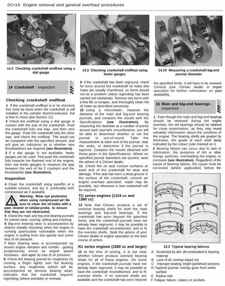
2C•16 Engine removal and general overhaul procedures
14.2 Checking crankshaft endfloat using adial gauge
14.3 Checking crankshaft endfloat using 14.10 Measuring a crankshaft big-endfeeler gauges journal diameter
14 Crankshaft - inspection
Checking crankshaft endfloat1 If the crankshaft endfloat is to be checked,this must be done when the crankshaft is stillinstalled in the cylinder block/crankcase, butis free to move (see Section 11).2 Check the endfloat using a dial gauge incontact with the end of the crankshaft. Pushthe crankshaft fully one way, and then zerothe gauge. Push the crankshaft fully the otherway, and check the endfloat. The result canbe compared with the specified amount, andwill give an indication as to whether newthrustwashers are required (see illustration).3 If a dial gauge is not available, feelergauges can be used. First push the crankshaftfully towards the flywheel end of the engine,then use feeler gauges to measure the gapbetween the web of No 2 crankpin and thethrustwasher (see illustration).
Inspection
4 Clean the crankshaft using paraffin or asuitable solvent, and dry it, preferably withcompressed air if available.
Warning: Wear eye protectionwhen using compressed air! Besure to clean the oil holes with a
pipe cleaner or similar probe, to ensurethat they are not obstructed.5 Check the main and big-end bearing journalsfor uneven wear, scoring, pitting and cracking.6 Big-end bearing wear is accompanied bydistinct metallic knocking when the engine isrunning (particularly noticeable when theengine is pulling from low speed) and someloss of oil pressure.7 Main bearing wear is accompanied bysevere engine vibration and rumble - gettingprogressively worse as engine speedincreases - and again by loss of oil pressure.8 Check the bearing journal for roughness byrunning a finger lightly over the bearingsurface. Any roughness (which will beaccompanied by obvious bearing wear)indicates that the crankshaft requiresregrinding (where possible) or renewal.
9 If the crankshaft has been reground, checkfor burrs around the crankshaft oil holes (theholes are usually chamfered, so burrs shouldnot be a problem unless regrinding has beencarried out carelessly). Remove any burrs witha fine file or scraper, and thoroughly clean theoil holes as described previously.10 Using a micrometer, measure thediameter of the main and big-end bearingjournals, and compare the results with theSpecifications (see illustration). Bymeasuring the diameter at a number of pointsaround each journal's circumference, you willbe able to determine whether or not thejournal is out-of-round. Take themeasurement at each end of the journal, nearthe webs, to determine if the journal istapered. Compare the results obtained withthose given in the Specifications. Where nospecified journal diameters are quoted, seekthe advice of a Citroen dealer.11 Check the oil seal contact surfaces ateach end of the crankshaft for wear anddamage. If the seal has worn a deep groove inthe surface of the crankshaft, consult anengine overhaul specialist; repair may bepossible, but otherwise a new crankshaft willbe required.
TU series engines (1124 cc and1360 cc)
12 Note that Citroen produce a set ofoversize bearing shells for both the mainbearings and big-end bearings. If thecrankshaft has worn beyond the specifiedlimits, and the crankshaft journals have notalready been reground, it may be possible tohave the crankshaft reconditioned, and to fitthe oversize shells. Seek the advice of yourCitroen dealer or engine specialist on the bestcourse of action.
XU series engines (1580 cc and larger)13 At the time of writing, it is not clearwhether Citroen produce oversize bearingshells for all of these engines. On someengines, if the crankshaft journals have notalready been reground, it may be possible tohave the crankshaft reconditioned, and to fitoversize shells. If no oversize shells areavailable and the crankshaft has worn beyond
the specified limits, it will have to be renewed.Consult your Citroen dealer or enginespecialist for further information on partsavailability.
1 Even though the main and big-end bearingsshould be renewed during the engineoverhaul, the old bearings should be retainedfor close examination, as they may revealvaluable information about the condition ofthe engine. The bearing shells are graded bythickness, the grade of each shell beingindicated by the colour code marked on it.2 Bearing failure can occur due to lack oflubrication, the presence of dirt or otherforeign particles, overloading the engine, orcorrosion (see illustration). Regardless of thecause of bearing failure, the cause must becorrected (where applicable) before the
15.2 Typical bearing failures
A Scratched by dirt; dirt embedded in bearingmaterial
B Lack of oil; overlay wiped outC Improper seating; bright (polished) sectionsD Tapered journal; overlay gone from entire
surfaceE Radius rideF Fatigue failure; craters or pockets
15 Main and big-end bearings -inspection
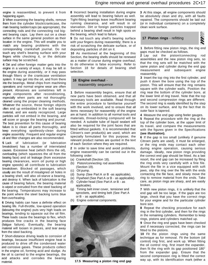
Engine removal and general overhaul procedures 2C•17
engine is reassembled, to prevent it fromhappening again.3 When examining the bearing shells, removethem from the cylinder block/crankcase, themain bearing ladder/caps (as appropriate), theconnecting rods and the connecting rod big-end bearing caps. Lay them out on a cleansurface in the same general position as theirlocation in the engine. This will enable you tomatch any bearing problems with thecorresponding crankshaft journal. Do nottouch any shell's bearing surface with yourfingers while checking it, or the delicatesurface may be scratched.4 Dirt and other foreign matter gets into theengine in a variety of ways. It may be left inthe engine during assembly, or it may passthrough filters or the crankcase ventilationsystem. It may get into the oil, and from thereinto the bearings. Metal chips from machiningoperations and normal engine wear are oftenpresent. Abrasives are sometimes left inengine components after reconditioning,especially when parts are not thoroughlycleaned using the proper cleaning methods.Whatever the source, these foreign objectsoften end up embedded in the soft bearingmaterial, and are easily recognized. Largeparticles will not embed in the bearing, andwill score or gouge the bearing and journal.The best prevention for this cause of bearingfailure is to clean all parts thoroughly, andkeep everything spotlessly-clean duringengine assembly. Frequent and regular engineoil and filter changes are also recommended.
5 Lack of lubrication (or lubricationbreakdown) has a number of interrelatedcauses. Excessive heat (which thins the oil),overloading (which squeezes the oil from thebearing face) and oil leakage (from excessivebearing clearances, worn oil pump or highengine speeds) all contribute to lubricationbreakdown. Blocked oil passages, whichusually are the result of misaligned oil holes ina bearing shell, will also oil-starve a bearing,and destroy it. When lack of lubrication is thecause of bearing failure, the bearing materialis wiped or extruded from the steel backing ofthe bearing. Temperatures may increase tothe point where the steel backing turns bluefrom overheating.
6 Driving habits can have a definite effect onbearing life. Full-throttle, low-speed operation(labouring the engine) puts very high loads onbearings, tending to squeeze out the oil film.These loads cause the bearings to flex, whichproduces fine cracks in the bearing face(fatigue failure). Eventually, the bearingmaterial will loosen in pieces, and tear awayfrom the steel backing.7 Short-distance driving leads to corrosion ofbearings, because insufficient engine heat isproduced to drive off the condensed waterand corrosive gases. These products collectin the engine oil, forming acid and sludge. Asthe oil is carried to the engine bearings, theacid attacks and corrodes the bearingmaterial.
8 Incorrect bearing installation during engineassembly will lead to bearing failure as well.Tight-fitting bearings leave insufficient bearingrunning clearance, and will result in oilstarvation. Dirt or foreign particles trappedbehind a bearing shell result in high spots onthe bearing, which lead to failure.9 Do not touch any shell's bearing surfacewith your fingers during reassembly; there is arisk of scratching the delicate surface, or ofdepositing particles of dirt on it.10 As mentioned at the beginning of thisSection, the bearing shells should be renewedas a matter of course during engine overhaul;to do otherwise is false economy. Refer toSection 18 for details of bearing shellselection.
1 Before reassembly begins, ensure that allnew parts have been obtained, and that allnecessary tools are available. Read throughthe entire procedure to familiarise yourselfwith the work involved, and to ensure that allitems necessary for reassembly of the engineare at hand. In addition to all normal tools andmaterials, thread-locking compound will beneeded. A suitable tube of liquid sealant willalso be required for the joint faces that arefitted without gaskets. It is recommended thatCitroen's own product(s) are used, which arespecially formulated for this purpose; therelevant product names are quoted in the textof each Section where they are required.2 In order to save time and avoid problems,engine reassembly can be carried out in thefollowing order:(a) Crankshaft (Section 18).(b) Piston/connecting rod assemblies
(Section 19).(c) Oil pump.(d) Sump (See Part A or B -as applicable).(e) Flywheel (See Part A or B - as applicable).(f) Cylinder head (See Part A or B - as
applicable).(g) Timing belt inner cover, tensioner and
sprockets, and timing belt (See Part Aor B - as applicable).
(h) Engine external components.
3 At this stage, all engine components shouldbe absolutely clean and dry, with all faultsrepaired. The components should be laid out(or in individual containers) on a completelyclean work surface.
17 Piston rings - refitting
17.5 Measuring a piston ring end gap
1 Before fitting new piston rings, the ring endgaps must be checked as follows.2 Lay out the piston/connecting rodassemblies and the new piston ring sets, sothat the ring sets will be matched with thesame piston and cylinder during the end gapmeasurement and subsequent enginereassembly.3 Insert the top ring into the first cylinder, andpush it down the bore using the top of thepiston. This will ensure that the ring remainssquare with the cylinder walls. Position thering near the bottom of the cylinder bore, atthe lower limit of ring travel. Note that the topand second compression rings are different.The second ring is easily identified by the stepon its lower surface, and by the fact that itsouter face is tapered.4 Measure the end gap using feeler gauges.5 Repeat the procedure with the ring at thetop of the cylinder bore, at the upper limit ofits travel, and compare the measurementswith the figures given in the Specifications(see illustration).6 If the gap is too small (unlikely if genuineCitroen parts are used), it must be enlarged,or the ring ends may contact each otherduring engine operation, causing seriousdamage. Ideally, new piston rings providingthe correct end gap should be fitted. As a lastresort, the end gap can be increased by filingthe ring ends very carefully with a fine file.Mount the file in a vice equipped with softjaws, slip the ring over the file with the endscontacting the file face, and slowly move thering to remove material from the ends. Takecare, as piston rings are sharp, and are easilybroken.7 With new piston rings, it is unlikely that theend gap will be too large. If the gaps are toolarge, check that you have the correct ringsfor your engine and for the particular cylinderbore size.8 Repeat the checking procedure for eachring in the first cylinder, and then for the ringsin the remaining cylinders. Remember to keeprings, pistons and cylinders matched up.9 Once the ring end gaps have been checkedand if necessary corrected, the rings can befitted to the pistons.10 Fit the piston rings using the sametechnique as for removal. Fit the bottom (oilcontrol) ring first, and work up. When fittingthe oil control ring, first insert the expander,then fit the ring with its gap positioned 180°from the expander gap. Ensure that thesecond compression ring is fitted the correctway up, with its identification mark (either a
16 Engine overhaul -reassembly sequence
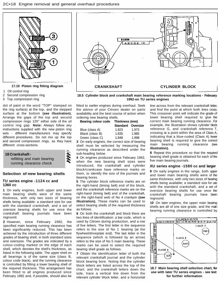
2C•18 Engine removal and general overhaul procedures
17.10 Piston ring fitting diagram
1 Oil control ring2 Second compression ring3 Top compression ring
dot of paint or the word "TOP" stamped onthe ring surface) at the top, and the steppedsurface at the bottom (see illustration).Arrange the gaps of the top and secondcompression rings 120° either side of the oilcontrol ring gap. Note: Always follow anyinstructions supplied with the new piston ringsets - different manufacturers may specifydifferent procedures. Do not mix up the topand second compression rings, as they havedifferent cross-sections.
Selection of new bearing shells
TU series engine -1124 cc and1360 cc1 On early engines, both upper and lowermain bearing shells were of the samethickness, with only two sizes of bearingshells being available: a standard size for usewith the standard crankshaft, and a set ofoversize bearing shells for use once thecrankshaft bearing journals have beenreground.2 However, since February 1992, thespecified main bearing running clearance hasbeen significantly reduced. This has beenachieved by the introduction of three differentgrades of bearing shell, in both standard sizesand oversizes. The grades are indicated by acolour-coding marked on the edge of eachshell, which denotes the shell's thickness, aslisted in the following table. The upper shell onall bearings is of the same size (class B,colour code black), and the running clearanceis controlled by fitting a lower bearing shell ofthe required thickness. This arrangement hasbeen fitted to all engines produced sinceFebruary 1992 and, if possible, should also be
18.5 Cylinder block and crankshaft main bearing reference marking locations - February1992-on TU series engines
fitted to earlier engines during overhaul. Seekthe advice of your Citroen dealer on partsavailability and the best course of action whenordering new bearing shells.
Bearing colour code Thickness (mm)Standard Oversize
Blue (class A) 1.823 1.973Black (class B) 1.835 1.985Green (class C) 1.848 1.998
3 On early engines, the correct size of bearingshell must be selected by measuring therunning clearance as described under thesub-heading below.4 On engines produced since February 1992,when the new bearing shell sizes wereintroduced, the crankshaft and cylinderblock/crankcase have reference marks onthem, to identify the size of the journals andbearing bores.5 The cylinder block reference marks are onthe right-hand (timing belt) end of the block,and the crankshaft reference marks are on theright-hand (timing belt) end of the crankshaft,on the right-hand web of No 4 crankpin (seeillustration). These marks can be used toselect bearing shells of the required thicknessas follows.6 On both the crankshaft and block there aretwo lines of identification: a bar code, which isused by Citroen during production, and a rowof five letters. The first letter in the sequencerefers to the size of No 1 bearing (at theflywheel/driveplate end). The last letter in thesequence (which is followed by an arrow)refers to the size of No 5 main bearing. Thesemarks can be used to select the requiredbearing shell grade as follows.7 Obtain the identification letter of both therelevant crankshaft journal and the cylinderblock bearing bore. Noting that the cylinderblock letters are listed across the top of thechart, and the crankshaft letters down theside, trace a vertical line down from therelevant cylinder block letter, and a horizontal
line across from the relevant crankshaft letter,and find the point at which both lines cross.This crossover point will indicate the grade oflower bearing shell required to give thecorrect main bearing running clearance. Forexample, the illustration shows cylinder blockreference G, and crankshaft reference T,crossing at a point within the area of Class A,indicating that a blue-coded (Class A) lowerbearing shell is required to give the correctmain bearing running clearance (seeillustration).8 Repeat this procedure so that the requiredbearing shell grade is obtained for each of thefive main bearing journals.
XU series engine -1580 cc and larger9 On early engines in the range, both upperand lower main bearing shells were of thesame thickness, with only two sizes of bearingshells being available; a standard size for usewith the standard crankshaft, and a set ofoversize bearing shells for use once thecrankshaft bearing journals have beenreground.10 On later engines, the upper main bearingshells are all of one size grade, and the mainbearing running clearance is controlled by
18.7 Main bearing shell selection chart, foruse with later TU series engines - see text
for further information
CRANKSHAFT CYLINDER BLOCK
A B C D E
18 Crankshaft -refitting and main bearingrunning clearance check
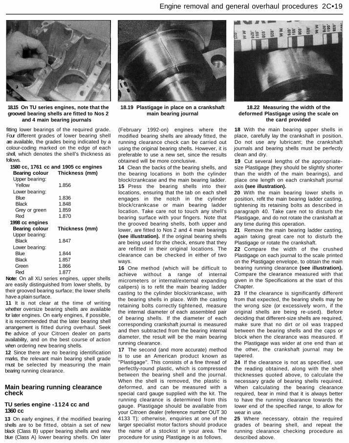
Engine removal and general overhaul procedures 2C•19
18.15 On TU series engines, note that thegrooved bearing shells are fitted to Nos 2
and 4 main bearing journals
fitting lower bearings of the required grade.Four different grades of lower bearing shellare available, the grades being indicated by acolour-coding marked on the edge of eachshell, which denotes the shell's thickness asfollows.
1580 cc, 1761 cc and 1905 cc enginesBearing colour Thickness (mm)Upper bearing:Yellow 1.856
Lower bearing:Blue 1.836Black 1.848Grey or green 1.859Red 1.870
1998 cc enginesBearing colour Thickness (mm)Upper bearing:Black 1.847
Lower bearing:Blue 1.844Black 1.857Green 1.866Red 1.877
Note: On all XU series engines, upper shellsare easily distinguished from lower shells, bytheir grooved bearing surface; the lower shellshave a plain surface.11 It is not clear at the time of writingwhether oversize bearing shells are availablefor later engines. On early engines, if possible,it is recommended that the later bearing shellarrangement is fitted during overhaul. Seekthe advice of your Citroen dealer on partsavailability, and on the best course of actionwhen ordering new bearing shells.12 Since there are no bearing identificationmarks, the relevant main bearing shell grademust be selected by measuring the mainbearing running clearance.
Main bearing running clearancecheck
TU series engine -1124 cc and1360 cc13 On early engines, if the modified bearingshells are to be fitted, obtain a set of newblack (Class B) upper bearing shells and newblue (Class A) lower bearing shells. On later
18.19 Plastigage in place on a crankshaftmain bearing journal
(February 1992-on) engines where themodified bearing shells are already fitted, therunning clearance check can be carried outusing the original bearing shells. However, it ispreferable to use a new set, since the resultsobtained will be more conclusive.14 Clean the backs of the bearing shells, andthe bearing locations in both the cylinderblock/crankcase and the main bearing ladder.15 Press the bearing shells into theirlocations, ensuring that the tab on each shellengages in the notch in the cylinderblock/crankcase or main bearing ladderlocation. Take care not to touch any shell'sbearing surface with your fingers. Note thatthe grooved bearing shells, both upper andlower, are fitted to Nos 2 and 4 main bearings(see illustration). If the original bearing shellsare being used for the check, ensure that theyare refitted in their original locations. Theclearance can be checked in either of twoways.16 One method (which will be difficult toachieve without a range of internalmicrometers or internal/external expandingcalipers) is to refit the main bearing laddercasting to the cylinder block/crankcase, withthe bearing shells in place. With the castingretaining bolts correctly tightened, measurethe internal diameter of each assembled pairof bearing shells. If the diameter of eachcorresponding crankshaft journal is measuredand then subtracted from the bearing internaldiameter, the result will be the main bearingrunning clearance.17 The second (and more accurate) methodis to use an American product known as"Plastigage". This consists of a fine thread ofperfectly-round plastic, which is compressedbetween the bearing shell and the journal.When the shell is removed, the plastic isdeformed, and can be measured with aspecial card gauge supplied with the kit. Therunning clearance is determined from thisgauge. Plastigage should be available fromyour Citroen dealer (reference number OUT 304133 T); otherwise, enquiries at one of thelarger specialist motor factors should producethe name of a stockist in your area. Theprocedure for using Plastigage is as follows.
18.22 Measuring the width of thedeformed Plastigage using the scale on
the card provided
18 With the main bearing upper shells inplace, carefully lay the crankshaft in position.Do not use any lubricant; the crankshaftjournals and bearing shells must be perfectlyclean and dry.19 Cut several lengths of the appropriate-size Plastigage (they should be slightly shorterthan the width of the main bearings), andplace one length on each crankshaft journalaxis (see illustration).20 With the main bearing lower shells inposition, refit the main bearing ladder casting,tightening its retaining bolts as described inparagraph 40. Take care not to disturb thePlastigage, and do not rotate the crankshaft atany time during this operation.21 Remove the main bearing ladder casting,again taking great care not to disturb thePlastigage or rotate the crankshaft.22 Compare the width of the crushedPlastigage on each journal to the scale printedon the Plastigage envelope, to obtain the mainbearing running clearance (see illustration).Compare the clearance measured with thatgiven in the Specifications at the start of thisChapter.23 If the clearance is significantly differentfrom that expected, the bearing shells may bethe wrong size (or excessively worn, if theoriginal shells are being re-used). Beforedeciding that different-size shells are required,make sure that no dirt or oil was trappedbetween the bearing shells and the caps orblock when the clearance was measured. Ifthe Plastigage was wider at one end than atthe other, the crankshaft journal may betapered.24 If the clearance is not as specified, usethe reading obtained, along with the shellthicknesses quoted above, to calculate thenecessary grade of bearing shells required.When calculating the bearing clearancerequired, bear in mind that it is always betterto have the running clearance towards thelower end of the specified range, to allow forwear in use.25 Where necessary, obtain the requiredgrades of bearing shell, and repeat therunning clearance checking procedure asdescribed above.

2C•20 Engine removal and general overhaul procedures
18.29 On XU series engines, all the lowershells have a plain bearing surface. Ensurethat the tab (arrowed) is correctly located
in the cap
26 On completion, carefully scrape away alltraces of the Plastigage material from thecrankshaft and bearing shells. Use yourfingernail, or a wooden or plastic scraperwhich is unlikely to score the bearingsurfaces.
XU series engine -1580 cc and larger27 On early engines, if the modified bearingshells are to be fitted, obtain a set of newupper bearing shells, and new green or grey(as applicable) lower bearing shells (seeparagraph 10). On later engines where themodified bearing shells are already fitted, therunning clearance check can be carried outusing the original bearing shells. However, it ispreferable to use a new set, since the resultsobtained will be more conclusive.28 Clean the backs of the bearing shells, andthe bearing locations in both the cylinderblock/crankcase and the main bearing caps.29 Press the bearing shells into theirlocations, ensuring that the tab on each shellengages in the notch in the cylinderblock/crankcase or bearing cap. Take carenot to touch any shell's bearing surface withyour fingers. Note that the upper bearingshells all have a grooved bearing surface,
18.35 Refitting a crankshaft thrustwasher- TU series engine
whereas the lower shells have a plain bearingsurface (see illustration). If the originalbearing shells are being used for the check,ensure that they are refitted in their originallocations.30 The clearance can be checked in either oftwo ways.31 One method (which will be difficult toachieve without a range of internalmicrometers or internal/external expandingcalipers) is to refit the main bearing caps tothe cylinder block/crankcase, with bearingshells in place. With the cap retaining boltstightened to the specified torque, measure theinternal diameter of each assembled pair ofbearing shells. If the diameter of eachcorresponding crankshaft journal is measuredand then subtracted from the bearing internaldiameter, the result will be the main bearingrunning clearance.32 The second, and more accurate, methodis to use Plastigage. The method is asdescribed above in paragraphs 17 to 26,substituting "main bearing caps" for allreferences to the main bearing ladder casting.33 Note that Citroen do not specify a mainbearing running clearance for the 1580 cc,1761 cc, or 1905 cc engines. The figure given
18.37 Refitting the oil pump drive chainand sprocket - TU series engine
18.38 Apply a thin film of suitable sealantto the cylinder block/crankcase mating
surface . . .
18.36 Ensure each bearing shell tab(arrowed) is correctly located, and
lubricate the shell with clean engine oil
in the Specifications is a guide figure which istypical for this type of engine. On theseengines, therefore, always refer to yourCitroen dealer for details of the exact runningclearance before condemning thecomponents concerned.
Final crankshaft refitting
TU series engine -1124 cc and1360 cc34 Carefully lift the crankshaft out of thecylinder block once more.35 Using a little grease, stick the upperthrustwashers to each side of the No 2 mainbearing upper location; ensure that the oilwaygrooves on each thrustwasher face outwards(away from the cylinder block) (seeillustration).36 Place the bearing shells in their locationsas described above in paragraphs 14 and 15.If new shells are being fitted, ensure that alltraces of protective grease are cleaned offusing paraffin. Wipe dry the shells andconnecting rods with a lint-free cloth. Liberallylubricate each bearing shell in the cylinderblock/crankcase with clean engine oil (seeillustration).37 Refit the Woodruff key, then slide on theoil pump drive sprocket, and locate the drivechain on the sprocket (see illustration).Lower the crankshaft into position so thatNos 2 and 3 cylinder crankpins are at TDC.Check the crankshaft endfloat as described inSection 14.38 Thoroughly degrease the mating surfacesof the cylinder block/crankcase and the mainbearing ladder. Apply a thin bead of suitablesealant to the cylinder block/crankcasemating surface of the main bearing laddercasting, then spread to an even film (seeillustration). Citroen recommend the use ofAuto Joint E10 sealant (available from yourCitroen dealer); in the absence of thespecified sealant, any suitable good-qualitysealant may be used.39 Lubricate the lower bearing shells with

Engine removal and general overhaul procedures 2C•21
18.39 . . . then lower the main bearingladder into position
clean engine oil, then refit the main bearingladder, ensuring that the shells are notdisplaced, and that the locating dowelsengage correctly (see illustration).40 Install the ten 11 mm main bearing ladderretaining bolts, and tighten them all by handonly. Working progressively outwards fromthe centre bolts, tighten the ten bolts, by aturn at a time, to the specified stage 1 torquewrench setting. Once all the bolts have beentightened to the stage 1 setting, angle-tightenthe bolts through the specified stage 2 settingusing a socket and extension bar. It isrecommended that an angle-measuringgauge is used during this stage of thetightening, to ensure accuracy (seeillustrations).
41 Refit all the 6 mm bolts securing the mainbearing ladder to the base of the cylinderblock, and tighten them to the specified
18.40a Tighten the ten 11 mm main bearingbolts to the stage 1 torque setting . . .
torque. Check that the crankshaft rotatesfreely.42 Refit the piston/connecting rod assembliesto the crankshaft as described in Section 19.43 Ensuring that the drive chain is correctlylocated on the sprocket, refit the oil pump andsump as described in Part A of this Chapter.44 Fit two new crankshaft oil seals asdescribed in Part A. Where removed, refit thecylinder head as described in Part A.
XU series engine -1580 cc and larger45 Carefully lift the crankshaft out of thecylinder block once more.46 Using a little grease, stick the upperthrustwashers to each side of the No 2 mainbearing upper location; ensure that the oilwaygrooves on each thrustwasher face outwards(away from the cylinder block) (seeillustration).47 Place the bearing shells in their locationsas described above in paragraphs 28 and 29.If new shells are being fitted, ensure that alltraces of protective grease are cleaned offusing paraffin. Wipe dry the shells andconnecting rods with a lint-free cloth.48 Liberally lubricate each bearing shell inthe cylinder block/crankcase with cleanengine oil. Lower the crankshaft into position,ensuring that the bearing shells andthrustwashers remain correctly seated.
18.40b . . . then angle-tighten themthrough the specified stage 2 angle
49 Using a little grease, stick the lowerthrustwashers to each side of the No 2 mainbearing cap location; ensure that the oilwaygrooves on each thrustwasher face outwards(away from the cap).50 Before fitting the bearing caps, check thecrankshaft endfloat as described in Sec-tion 14.51 Fit main bearing caps Nos 2 to 5 to theircorrect locations, ensuring that they are fittedthe correct way round (the bearing shell tabrecesses in the block and caps must be onthe same side). Insert the bolts/nuts,tightening them only loosely at this stage.52 Apply a small amount of sealant to the No1 main bearing cap face mating on thecylinder block, around the sealing strip holes(see illustration).53 Locate the tab of each sealing strip overthe pins on the base of No 1 bearing cap, andpress the strips into the bearing cap grooves.It is now necessary to obtain two thin metalstrips, of 0.25 mm thickness or less, in orderto prevent the strips moving when the cap isbeing fitted. Citroen garages use the toolshown, which acts as a clamp. Metal strips(such as old feeler blades) can be used,provided all burrs which may damage thesealing strips are first removed (seeillustrations).
18.46 Fitting a thrustwasher to No 2 main 18.52 Applying sealant to the cylinder 18.53a Fitting a sealing strip to No 1 mainbearing upper location - XU series engine block No 1 main bearing cap mating face bearing cap
If an angle-measuring gaugeis not available, use a dab ofwhite paint to makealignment marks between the
bolt head and casting prior totightening; the marks can then be usedto check that the bolt has been rotatedsufficiently during tightening.
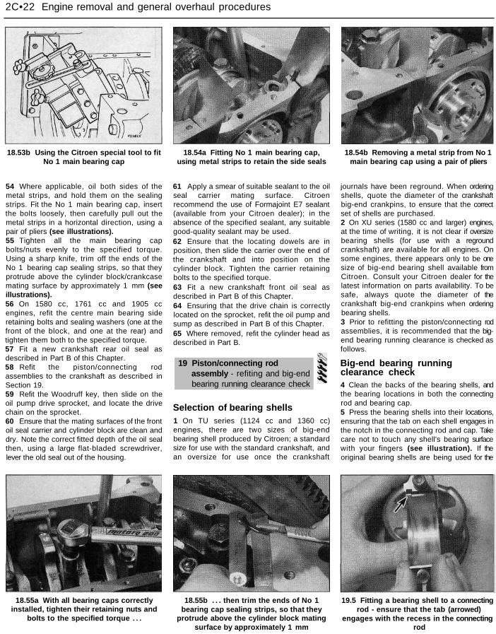
2C•22 Engine removal and general overhaul procedures
18.53b Using the Citroen special tool to fitNo 1 main bearing cap
18.54a Fitting No 1 main bearing cap,using metal strips to retain the side seals
18.54b Removing a metal strip from No 1main bearing cap using a pair of pliers
54 Where applicable, oil both sides of themetal strips, and hold them on the sealingstrips. Fit the No 1 main bearing cap, insertthe bolts loosely, then carefully pull out themetal strips in a horizontal direction, using apair of pliers (see illustrations).55 Tighten all the main bearing capbolts/nuts evenly to the specified torque.Using a sharp knife, trim off the ends of theNo 1 bearing cap sealing strips, so that theyprotrude above the cylinder block/crankcasemating surface by approximately 1 mm (seeillustrations).56 On 1580 cc, 1761 cc and 1905 ccengines, refit the centre main bearing sideretaining bolts and sealing washers (one at thefront of the block, and one at the rear) andtighten them both to the specified torque.57 Fit a new crankshaft rear oil seal asdescribed in Part B of this Chapter.58 Refit the piston/connecting rodassemblies to the crankshaft as described inSection 19.59 Refit the Woodruff key, then slide on theoil pump drive sprocket, and locate the drivechain on the sprocket.60 Ensure that the mating surfaces of the frontoil seal carrier and cylinder block are clean anddry. Note the correct fitted depth of the oil sealthen, using a large flat-bladed screwdriver,lever the old seal out of the housing.
61 Apply a smear of suitable sealant to the oilseal carrier mating surface. Citroenrecommend the use of Formajoint E7 sealant(available from your Citroen dealer); in theabsence of the specified sealant, any suitablegood-quality sealant may be used.62 Ensure that the locating dowels are inposition, then slide the carrier over the end ofthe crankshaft and into position on thecylinder block. Tighten the carrier retainingbolts to the specified torque.63 Fit a new crankshaft front oil seal asdescribed in Part B of this Chapter.64 Ensuring that the drive chain is correctlylocated on the sprocket, refit the oil pump andsump as described in Part B of this Chapter.65 Where removed, refit the cylinder head asdescribed in Part B.
Selection of bearing shells1 On TU series (1124 cc and 1360 cc)engines, there are two sizes of big-endbearing shell produced by Citroen; a standardsize for use with the standard crankshaft, andan oversize for use once the crankshaft
journals have been reground. When orderingshells, quote the diameter of the crankshaftbig-end crankpins, to ensure that the correctset of shells are purchased.2 On XU series (1580 cc and larger) engines,at the time of writing, it is not clear if oversizebearing shells (for use with a regroundcrankshaft) are available for all engines. Onsome engines, there appears only to be onesize of big-end bearing shell available fromCitroen. Consult your Citroen dealer for thelatest information on parts availability. To besafe, always quote the diameter of thecrankshaft big-end crankpins when orderingbearing shells.3 Prior to refitting the piston/connecting rodassemblies, it is recommended that the big-end bearing running clearance is checked asfollows.
Big-end bearing runningclearance check4 Clean the backs of the bearing shells, andthe bearing locations in both the connectingrod and bearing cap.5 Press the bearing shells into their locations,ensuring that the tab on each shell engages inthe notch in the connecting rod and cap. Takecare not to touch any shell's bearing surfacewith your fingers (see illustration). If theoriginal bearing shells are being used for the
18.55a With all bearing caps correctlyinstalled, tighten their retaining nuts and
bolts to the specified torque . . .
18.55b . . . then trim the ends of No 1bearing cap sealing strips, so that they
protrude above the cylinder block matingsurface by approximately 1 mm
19.5 Fitting a bearing shell to a connectingrod - ensure that the tab (arrowed)
engages with the recess in the connectingrod
19 Piston/connecting rodassembly - refiting and big-endbearing running clearance check
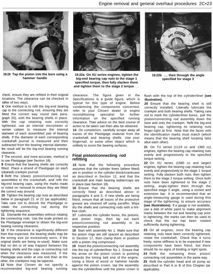
Engine removal and general overhaul procedures 2C•23
19.19 Tap the piston into the bore using ahammer handle
check, ensure they are refitted in their originallocations. The clearance can be checked ineither of two ways.6 One method is to refit the big-end bearingcap to the connecting rod, ensuring they arefitted the correct way round (see para-graph 20), with the bearing shells in place.With the cap retaining nuts correctlytightened, use an internal micrometer orvernier caliper to measure the internaldiameter of each assembled pair of bearingshells. If the diameter of each correspondingcrankshaft journal is measured and thensubtracted from the bearing internal diameter,the result will be the big-end bearing runningclearance.7 The second, and more accurate, method isto use Plastigage (see Section 18).8 Ensure that the bearing shells are correctlyfitted. Place a strand of Plastigage on each(cleaned) crankpin journal.9 Refit the (clean) piston/connecting rodassemblies to the crankshaft, and refit thebig-end bearing caps, using the marks madeor noted on removal to ensure they are fittedthe correct way around.10 Tighten the bearing cap nuts as describedbelow in paragraph 21 or 22 (as applicable).Take care not to disturb the Plastigage orrotate the connecting rod during thetightening sequence.11 Dismantle the assemblies without rotatingthe connecting rods. Use the scale printed onthe Plastigage envelope to obtain the big-endbearing running clearance.12 If the clearance is significantly differentfrom that expected, the bearing shells may bethe wrong size (or excessively worn, if theoriginal shells are being re-used). Make surethat no dirt or oil was trapped between thebearing shells and the caps or connecting rodwhen the clearance was measured. If thePlastigage was wider at one end than at theother, the crankpins may be tapered.13 Note that Citroen do not specify arecommended big-end bearing running
19.22a On XU series engines, tighten thebig-end bearing cap nuts to the stage 1
specified torque, then fully slacken themand tighten them to the stage 2 torque . . .
clearance. The figure given in theSpecifications is a guide figure, which istypical for this type of engine. Beforecondemning the components concerned,refer to your Citroen dealer or enginereconditioning specialist for furtherinformation on the specified runningclearance. Their advice on the best course ofaction to be taken can then also be obtained.14 On completion, carefully scrape away alltraces of the Plastigage material from thecrankshaft and bearing shells. Use yourfingernail, or some other object which isunlikely to score the bearing surfaces.
Final piston/connecting rodrefitting15 Note that the following procedureassumes that the cylinder liners (where fitted)are in position in the cylinder block/crankcaseas described in Section 12, and that thecrankshaft and main bearing ladder/caps arein place (see Section 18).16 Ensure that the bearing shells arecorrectly fitted as described above inparagraphs 4 and 5. If new shells are beingfitted, ensure that all traces of the protectivegrease are cleaned off using paraffin. Wipedry the shells and connecting rods with a lint-free cloth.17 Lubricate the cylinder bores, the pistons,and piston rings, then lay out eachpiston/connecting rod assembly in itsrespective position.18 Start with assembly No 1. Make sure thatthe piston rings are still spaced as describedin Section 17, then clamp them in positionwith a piston ring compressor.19 Insert the piston/connecting rod assemblyinto the top of cylinder/liner No 1. Ensure thatthe arrow on the piston crown is pointingtowards the timing belt end of the engine.Using a block of wood or hammer handleagainst the piston crown, tap the assemblyinto the cylinder/liner until the piston crown is
19.22b . . . then through the anglespecified for stage 3
flush with the top of the cylinder/liner (seeillustration).20 Ensure that the bearing shell is stillcorrectly installed. Liberally lubricate thecrankpin and both bearing shells. Taking carenot to mark the cylinder/liner bores, pull thepiston/connecting rod assembly down thebore and onto the crankpin. Refit the big-endbearing cap, tightening its retaining nutsfinger-tight at first. Note that the faces withthe identification marks must match (whichmeans that the bearing shell locating tabsabut each other).
21 On TU series (1124 cc and 1360 cc)engines, tighten the bearing cap retaining nutsevenly and progressively to the specifiedtorque setting.22 On XU series (1580 cc and larger)engines, tighten the bearing cap retaining nutsevenly and progressively to the stage 1 torquesetting. Fully slacken both nuts, then tightenthem to the stage 2 torque setting. Once bothnuts have been tightened to the stage 2setting, angle-tighten them through thespecified stage 3 angle, using a socket andextension bar. It is recommended that anangle-measuring gauge is used during thisstage of the tightening, to ensure accuracy(see illustrations). If a gauge is not available,use a dab of white paint to make alignmentmarks between the nut and bearing cap priorto tightening; the marks can then be used tocheck that the nut has been rotatedsufficiently during tightening.
23 On all engines, once the bearing capretaining nuts have been correctly tightened,rotate the crankshaft. Check that it turnsfreely; some stiffness is to be expected if newcomponents have been fitted, but thereshould be no signs of binding or tight spots.24 Refit the remaining three piston/connecting rod assemblies in the same way.25 Refit the cylinder head and oil pump asdescribed in Part A or B of this Chapter (asapplicable).
2C•24 Engine removal and general overhaul procedures
20 Engine -initial start-up after overhaul
1 With the engine refitted in the car, double-check the engine oil and coolant levels. Makea final check that everything has beenreconnected, and that there are no tools orrags left in the engine compartment.2 Remove the spark plugs. On models with adistributor, disable the ignition system bydisconnecting the ignition HT coil lead fromthe distributor cap, and earthing it on thecylinder block. Use a jumper lead or similarwire to make a good connection. On modelswith a static (distributorless) ignition system,disable the ignition system by disconnectingthe LT wiring connector from the ignition HT
coil(s), referring to Chapter 5 for furtherinformation.3 Turn the engine on the starter until the oilpressure warning light goes out. Refit thespark plugs, and reconnect the spark plug(HT) leads, referring to Chapter 1 for furtherinformation. Reconnect any HT leads or wiringwhich was disconnected in paragraph 2.4 Start the engine, noting that this may take alittle longer than usual, due to the fuel systemcomponents being empty.5 While the engine is idling, check for fuel,water and oil leaks. Don't be alarmed if thereare some odd smells and smoke from partsgetting hot and burning off oil deposits. On1998 cc 16-valve engines, some valvegearnoise may be heard at first; this shoulddisappear as the oil circulates fully around theengine, and normal pressure is restored in the
hydraulic tappet mechanisms.6 Assuming all is well, keep the engine idlinguntil hot water is felt circulating through thetop hose. Check the ignition timing and idlespeed and mixture (as appropriate), thenswitch the engine off.7 After a few minutes, recheck the oil andcoolant levels as described in Chapter 1, andtop-up as necessary.8 If they were tightened as described, there isno need to re-tighten the cylinder head boltsonce the engine has first run after reassembly.9 If new pistons, rings or crankshaft bearingshave been fitted, the engine must be treated asnew and run-in for the first 500 miles(800 km). Do not operate the engine at full-throttle, or allow it to labour at low enginespeeds in any gear. It is recommended that theoil and filter be changed at the end of this period.