Chapter 2 HVAC in the Southeastern Climate Region Manuals/Chapter2...Heating, ventilation, and air...
54
49 INTRODUCTION Heating, ventilation, and air conditioning (HVAC) are the equipment and systems that control the conditions and distribution of indoor air. Indoor air must be comfortable, healthy, and safe. HVAC systems address these needs by control- ling indoor temperature and relative humidity (RH), and by filtering air and providing ventila- tion air to improve air quality. HVAC systems also control ancillary effects such as building pressure and direction of airflow, which can affect the growth of mold inside a building and can impact the correct operation and venting of combustion equipment. Installing efficient HVAC equipment, scheduling and operating it in optimum fashion, and maintaining the sys- tems and controls will achieve a comfort- able and healthy indoor environment in an energy-efficient manner. ASHRAE Standard 180-2008 “Standard Practice for Inspection and Maintenance of Commercial Building HVAC Systems” provides guidance regarding inspection and maintenance practices for HVAC systems. Heating, ventilating, and air conditioning maintenance practices have a sig- nificant effect on a building’s energy use and the comfort of its occupants. HVAC systems are typically the largest users of energy in most buildings—about 45% of a typical office building’s energy use, compared with about 23% for lighting and 32% for internal equipment. HVAC AT-A-GLANCE Introduction Maintenance Considerations Regional Climate Demands Operations and Maintenance Practices Cooling Systems Heating Systems Air Distribution Systems Air Handler Units Ventilation Comfort Controls Health and Safety Mechanical Rooms Combustion Safety Limiting Loads from Devices Brought in by Employees Equipment Replacement or Upgrades Acronyms in this Chapter Chapter 2 | HVAC in the Southeastern Climate Region
Transcript of Chapter 2 HVAC in the Southeastern Climate Region Manuals/Chapter2...Heating, ventilation, and air...

49
IntroductIon
Heating, ventilation, and air conditioning (HVAC)
are the equipment and systems that control the
conditions and distribution of indoor air. Indoor
air must be comfortable, healthy, and safe.
HVAC systems address these needs by control-
ling indoor temperature and relative humidity
(RH), and by filtering air and providing ventila-
tion air to improve air quality. HVAC systems
also control ancillary effects such as building
pressure and direction of airflow, which can
affect the growth of mold inside a building and
can impact the correct operation and venting
of combustion equipment. Installing efficient
HVAC equipment, scheduling and operating it
in optimum fashion, and maintaining the sys-
tems and controls will achieve a comfort-
able and healthy indoor environment in an
energy-efficient manner. ASHRAE Standard
180-2008 “Standard Practice for Inspection
and Maintenance of Commercial Building HVAC Systems” provides guidance
regarding inspection and maintenance practices for HVAC systems.
Heating, ventilating, and air conditioning maintenance practices have a sig-
nificant effect on a building’s energy use and the comfort of its occupants. HVAC
systems are typically the largest users of energy in most buildings—about 45% of
a typical office building’s energy use, compared with about 23% for lighting and
32% for internal equipment.
HVAC At-A-GlAnCe
IntroductionMaintenance Considerations
Regional Climate Demands
Operations and Maintenance PracticesCooling Systems
Heating Systems
Air Distribution Systems
Air Handler Units
Ventilation
Comfort Controls
Health and SafetyMechanical Rooms
Combustion Safety
Limiting Loads from Devices Brought in by Employees
Equipment Replacement or Upgrades
Acronyms in this Chapter
Chapter 2 | HVAC in the Southeastern Climate Region
50 GREEn BUIlDInG OPERAtIOnS AnD MAIntEnAnCE MAnUAl
this chapter discusses operation and maintenance practices of common
types of HVAC equipment employed in the common (non-residential) spaces
of public housing authority (PHA) buildings in the southeastern United States.
Common spaces include offices, meeting rooms, laundry rooms, and commu-
nity gathering areas. the size and arrangement of common areas within public
housing buildings varies significantly from one PHA site to another. they range
from small single-zone detached buildings to large multi-story buildings with
common space areas distributed throughout the building. these spaces may be
served by a variety of HVAC systems.
Public housing office and common space may be designed and operated so
that occupants cannot meet individual comfort needs through access to oper-
able windows for ventilation and thermostats to adjust temperature. Sometimes
the cooling and heating system strictly maintains a “comfort zone” without re-
gard to whether or not occupants feel hot or cold, or even if anyone is present.
Complaints that areas are too hot or too cold can plague facility managers. these
factors point to the difficult tasks that the building HVAC engineer and the main-
tenance staff must carry out in order to balance occupant comfort with building
and equipment efficiency, while keeping maintenance costs low. It is a chal-
lenging task because comfort problems that affect employee productivity may
outweigh the cost of cooling, heating, or ventilating the building.
After discussing maintenance considerations and regional climate demands,
this chapter summarizes operation and maintenance practices of specific HVAC
equipment used in public housing. Due to the wide variety of building types and
of common spaces found in PHAs, the information is organized by primary type of
equipment. Within each section, a discussion with some tips for improved HVAC
operation is followed by maintenance guidance or a checklist. later sections in
this chapter cover recommendations on how to limit energy consumption from
devices brought in by employees, and issues to consider when planning equip-
ment replacement or upgrades.
Maintenance considerations
A good maintenance program maximizes equipment performance and life
expectancy in the most cost-effective manner. Good communication between
people familiar with the equipment and with management will help to estab-
lish realistic budgets. there are generally three ways to consider maintenance:
Reactive, Preventative, and Predictive.
reactIve MaIntenance is the practice of repairing or replacing equipment
only after operation is impaired or has ceased. Also referred to as “run-to- failure,”
this practice can diminish HVAC performance, resulting in more complaints
about comfort and reduced air quality control. Waiting until total equipment

HVAC In tHE SOUtHEAStERn ClIMAtE REGIOn 51
failure can also cause additional component damage and higher costs, especially
if the repairs must be made when emergency or overtime rates apply.
PreventatIve MaIntenance is performed according to a schedule or based
on actual equipment operation runtime. While more efficient than reactive main-
tenance, preventative maintenance may also result in inefficiencies. For example,
an air filter is often changed according to a calendar schedule, but this type of
activity may actually “waste” some of the useful life of the filter.
PredIctIve MaIntenance is based on the actual condition of equipment, but
it goes further than preventative maintenance. Predictive maintenance tracks
fault frequency and costs, and uses this information to predict when mainte-
nance should be implemented. While upfront costs to start and maintain a pre-
dictive maintenance program can be high, the U.S. Department of Energy (DOE)
Federal Energy Management Program (FEMP) claims this is a very cost effective
approach that yields savings that are ten times the cost of a predictive main-
tenance program. this program should also provide energy savings of 8–12%,
reduced maintenance costs of 25–30%, reduction in breakdowns by 70–75%,
and reduction in downtime by 35–45%.
the HVAC maintenance team must balance system efficiency and occupan-
cy comfort, which at times seems incompatible. this balance may be achieved
by considering the following, arranged from a broad to narrow focus:
• HuMan factors: Focusing on individuals’ comfort zones instead of main-
taining buildings at prescribed conditions may achieve both energy effi-
ciency and occupant comfort.
∞ Operate space conditioning and ventilation systems for occupant com-
fort during work periods; condition only as needed to control humidity
during unoccupied periods.
∞ Establish a policy of providing conditions within a range that occupants
can depend on so they can adjust clothing as needed. For instance, those
for whom an air conditioning setpoint of 75°F is too cold can plan to wear
long sleeves. Consider ASHRAE Comfort Standard 55 for guidance.
∞ Allow occupants to self-regulate temperature within a predetermined
range through better access to supply vents and thermostats.
∞ LocatIon, teMPerature, and Load factors: Focus on providing
temperature for spaces according to their function. Where possible, reduce
HVAC loads by establishing temperature setpoints for different spaces (e.g.,
hallways can be cooler in the winter and warmer in the summer than office
areas).
∞ externaL factors: Occupant comfort is often affected by factors such
as leaky or low-performance windows, heat gain or loss through poorly in-
sulated walls, and thermal stratification within the space. Energy savings can
be achieved through building envelope improvements such as reflective

52 GreenBuildinGOperatiOnsandMaintenanceManual
window blinds, exterior shading of walls and windows, and improved
thermalperformanceofwindowsandwalls.
• Low-cost or no-cost system modifications:inadditiontoopera-
tionandmaintenancepractices,anumberofrelativelylow-costorno-cost,
quick-returnmeasurescanreduceenergyconsumption.theyincludeseal-
ing ductwork, adjusting thermostat settings, improving operating proce-
dures,andautomatingsystemcontrols.consider,forexample,thatraising
coolingsetpointscanreducecoolingenergyconsumptionbyabout8%per
degreechange,while loweringheatingsetpointscan reduceheatingen-
ergyconsumptionbyabout4%perdegreechange,dependingupon the
climate zone.
regional climate demands
thismanualaddresseshot-humidandmixed-humidclimatezonesinthesouth-
easternandsouth-centralunitedstates.thisareacoversaboutone-thirdofthe
lower48states.thehot-humidportioncanbeconsideredacooling-dominated
region.themixed-humidregionhas,forthemostpart,acloserbalancebetween
summer and winter weather.
there are, however, consider-
ableclimatevariationswithin this
region, as measured by heating
degree days (Hdds) and cooling
degree days (cdds) (see Box 1).
therefore,theguidanceprovided
in this manual must, by neces-
sity,applyacrossawiderangeof
climates.
Heatingdesignrequirements
differ in various climate zones.
Winters vary substantially from
nearlynon-existentinsouthFlori-
datoabout5monthsinthemore
northerly areas. summers also
varyconsiderably,notsomuchby
temperatureasbydewpointtem-
perature (ameasureofhumidity)andbypersistenceandduration.Floridahas
dewpointtemperaturesthatremainabove72°Fforabout4months(June–sep-
tember)withlittlerespite.Washington,dc,hashighdewpointtemperatures,of-
teninthe70’sthroughoutmuchofJunethroughaugust,buttheyareinterrupted
intermittentlybycoldfrontswithsomewhatcooleranddryerair.thecommon
themeofhotandhumidweatherforportionsoftheyearhasrelevancetothe
figure 1.dominant u.s. cLimate regions
cOld/very cold
Mixed HuMid
HoT HuMid
HoT-dry/Mixed-dry
Marine
HVacintHesOutHeasterncliMatereGiOn 53
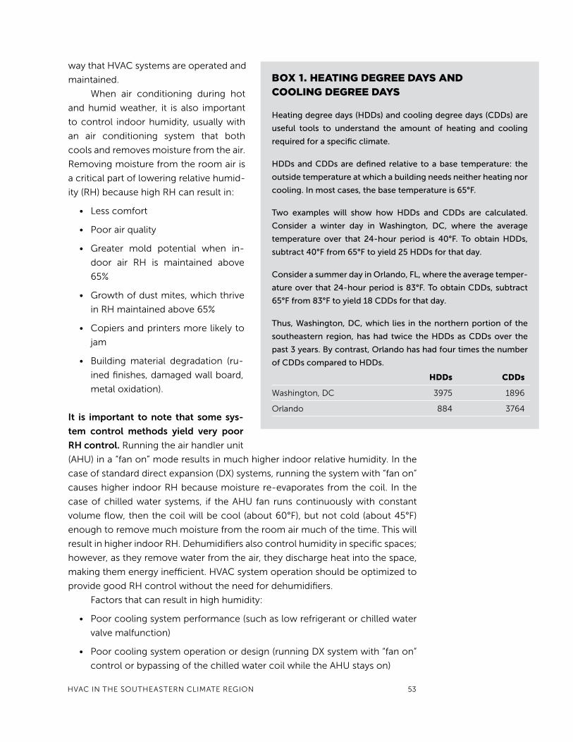
Box 1. Heating degree days and cooLing degree days
Heating degree days (HDDs) and cooling degree days (CDDs) are
useful tools to understand the amount of heating and cooling
required for a specific climate.
HDDs and CDDs are defined relative to a base temperature: the
outside temperature at which a building needs neither heating nor
cooling. In most cases, the base temperature is 65°F.
Two examples will show how HDDs and CDDs are calculated.
Consider a winter day in Washington, DC, where the average
temperature over that 24-hour period is 40°F. To obtain HDDs,
subtract 40°F from 65°F to yield 25 HDDs for that day.
Consider a summer day in Orlando, FL, where the average temper-
ature over that 24-hour period is 83°F. To obtain CDDs, subtract
65°F from 83°F to yield 18 CDDs for that day.
Thus, Washington, DC, which lies in the northern portion of the
southeastern region, has had twice the HDDs as CDDs over the
past 3 years. By contrast, Orlando has had four times the number
of CDDs compared to HDDs.
HDDs CDDs
Washington,dc 3975 1896
Orlando 884 3764
waythatHVacsystemsareoperatedand
maintained.
When air conditioning during hot
andhumidweather, it is also important
tocontrol indoorhumidity,usuallywith
an air conditioning system that both
coolsandremovesmoisturefromtheair.
removingmoisturefromtheroomairis
acriticalpartofloweringrelativehumid-
ity(rH)becausehighrHcanresultin:
• lesscomfort
• poorairquality
• Greater mold potential when in-
door air rH is maintained above
65%
• Growthofdustmites,whichthrive
inrHmaintainedabove65%
• copiersandprintersmorelikelyto
jam
• Building material degradation (ru-
inedfinishes,damagedwallboard,
metaloxidation).
it is important to note that some sys-
tem control methods yield very poor
rH control.runningtheairhandlerunit
(aHu)ina“fanon”moderesultsinmuchhigherindoorrelativehumidity.inthe
caseofstandarddirectexpansion(dx)systems,runningthesystemwith“fanon”
causeshigher indoorrHbecausemoisturere-evaporatesfromthecoil. inthe
caseofchilledwatersystems, if theaHufan runscontinuouslywithconstant
volumeflow,thenthecoilwillbecool(about60°F),butnotcold(about45°F)
enoughtoremovemuchmoisturefromtheroomairmuchofthetime.thiswill
resultinhigherindoorrH.dehumidifiersalsocontrolhumidityinspecificspaces;
however,astheyremovewaterfromtheair,theydischargeheatintothespace,
makingthemenergyinefficient.HVacsystemoperationshouldbeoptimizedto
providegoodrHcontrolwithouttheneedfordehumidifiers.
Factorsthatcanresultinhighhumidity:
• poorcoolingsystemperformance(suchaslowrefrigerantorchilledwater
valvemalfunction)
• poorcoolingsystemoperationordesign(runningdxsystemwith“fanon”
controlorbypassingofthechilledwatercoilwhiletheaHustayson)
54 GreenBuildinGOperatiOnsandMaintenanceManual
• leakybuildingenvelopeorductleakage
• Mechanicallydepressurizedbuilding
• unbalancedairdistribution
• Highlevelsofevaporation(e.g.,excessivecookingwithboilingwater,high
activityworkorexercise,indoorswimmingpoolorhottub).
operations and maintenance practices
HVac maintenance practices vary depending
on the typeofequipment,building,andexisting
envelopemeasures,aswell asbuilding location,
size,usepattern,andpurpose.thus,itisimpossi-
bletoidentifyspecificmaintenancepracticesthat
fit all circumstances. rather, use the following
guidelinestodevelopacombinationofpractices
andschedulesthatwillbestservetheoccupants’
needs, maintain good indoor air quality, reduce
energy consumption, and lessen environmental
impacts.
an energy audit is highly recommended as
aninitialsteptoimproveenergyefficiency.Vari-
ous levels of audits, from preliminary to com-
prehensive,canbeobtainedfromenergyservice
companies,architectureandengineeringfirms,orutilities.(notetogovernment
facility managers: the Federal energy Management program (FeMp) can also
providethistechnicalsupportonareimbursablesub-contractbasis).
cooling systems
thecoolingsystemsprimarilyusedinsoutheasternpublichousingcangener-
allybeclassifiedasdirect expansionorchilled watersystems.Mostaredirect
expansionsystemsthatrequireanoutdoorcondenserunittoexchangeheatto
theoutdoorair.thecondenserunitwillbediscussedhereandtheindoorairheat
exchangeofthissystemwillbediscussedintheairdistributionsystemsection.
While not as common, some multi-story public housing buildings use chilled
watersystems.
This section covers the operations and maintenance of the following equipment:
cooling Systems
condenserunits,chillers,coolingtowers
Heating Systemselectricresistance;Heatpumps;GasFurnaces;
centralsteam,HotWater,andradiatorspaceHeating
systems
air distribution Systems
air Handler units
ventilation
comfort controls
thermostatsandVentilationsensors

HVacintHesOutHeasterncliMatereGiOn 55
Condenser Unit Operation
airconditionersthatusedirectexpansion(dx)coolingcirculaterefrigerantina
circuitbetweentwoheatexchangesurfaces(seeFigure2).theprocessbegins
withpressurizedrefrigerantatthecompressor(#1inthefigure)thatistransferred
throughanexpansionvalve (#2)beforeentering theevaporatorcoil (#3).the
evaporatorislocatedinsidetheaHuwhereafanblowsairthroughittopickup
cooling.therefrigerantthentravelsbacktothecondenserunit(#4)locatedout-
doors.refrigerantgivesupheattooutdoorsthenthecyclebeginsagain.
figure 2. Heat excHange in a direct expansion system in summer 1)compressor2)expansionvalve3)evaporator4)condenser
Service technician using sensor to locate refrigerant leak around condenser coil.
Mirror and dye used to locate leak.
allillustrationsandphotographsinthischapterarecourtesyofJimcummingsandcharlesWithers,unlessotherwisenoted.

56 GREEn BUIlDInG OPERAtIOnS AnD MAIntEnAnCE MAnUAl
the condenser unit (or outdoor unit) contains the compressor, condenser,
a fan that moves air across the condenser coil, and electronic components. Be-
cause this equipment is outdoors, it can become dirty and will be exposed to
corrosive environmental factors over time. Heat transfer relies upon the coil sur-
faces remaining fairly clean. therefore, the condenser coil must be protected
from anything that interferes with airflow around and through it.
Chiller Operation
A chiller uses a refrigeration process to cool water that is transported into the
building to provide space cooling. How the chillers are operated and the method
used to “condition” water significantly affects operating efficiency. Historically,
chillers have worked most efficiently when operating at full-load rather than
part-load. Buildings, however, produce full-load only a fraction of the time. In
recent years, a new generation of variable-speed, variable-capacity chillers have
entered the marketplace. Some of these units operate with magnetic bearings,
allowing very high-speed, variable-capacity operation with very low noise and
very high efficiency at part-load (as low as 320 Watts per ton at 40% load factor).
A chiller operates with two water loops. One loop takes water through the
evaporator, which lowers the temperature of the chilled water. the other loop
takes water through the condenser, which discharges waste heat to ambient air.
A number of measures can increase chiller efficiency:
• Lower enterIng condenser water teMPeratures will yield high-
er chiller efficiency. Decrease condenser water temperature by running it
through a cooling tower. Operate the chilled water system to provide a
relatively large temperature difference (of water delivered to the evapora-
condenser unIt MaIntenance guIdance
Maintenance Description
Annually
Outdoor coil Clean the outdoor coil and remove any debris such as leaves or dirt from around or near the outdoor unit. Repair damaged fins.Place protective cover over top of unit at the end of cooling season if it is located under a roof edge where ice can fall onto it during winter.
Refrigerant leaks Inspect tubes and coil for evidence of leaks. Have a leak test done and seal leak on system that requires refrigerant to be added.
Fan lubricate fan motor bearings according to manufacturer’s recommendation.Inspect fan for damage or unusual vibration or noise. tighten and adjust fan mounts as needed.
Electric power Inspect wiring and electric connections. tighten loose wires and replace weathered or nicked wiring.Measure heat pump amperage under operation and verify it is within manufacturer’s specifications. Repair or replace equipment operating outside specifications.
HVAC In tHE SOUtHEAStERn ClIMAtE REGIOn 57
tor) from supply to return: Return water should be 15°F warmer than the
supply water. If this differential drops to 10° or even 5°, the system efficien-
cy will decline substantially. Careful balancing of the chilled water system
flow rates through the various AHUs is important to maintaining the desired
supply-to-return temperature differential. Replacement of standard chilled
water valves with pressure independent valves can be a very cost-effective
means to achieve and maintain balanced chilled water flow and the target
15°F temperature differential.
• varIaBLe frequency drIves (VFDs) vary the flow rate of chilled water
through the building loop. this can save substantial pump energy use and
help to achieve the 15°F temperature differential. During colder weather,
water can be taken directly from the cooling tower to feed the chilled water
loop and thus provide “free cooling” without the use of the chiller.
• a sIMPLe and econoMIcaL cHILLer PLant controL network for
the chillers, pumps, and tower fans that automatically operates and se-
quences all equipment is a cost-effective way to optimize the energy ef-
ficiency of large complex systems. Designing and implementing such a
network can save $20 to $100 per installed ton per year.
the table on the following page provides guidance on important chill-
er maintenance practices that should occur at least annually in early spring in
preparation for cooling season.
58 GREEn BUIlDInG OPERAtIOnS AnD MAIntEnAnCE MAnUAl
Cooling Tower Operations
Cooling towers transfer heat from the condenser to the atmosphere using evap-
orative cooling. their primary maintenance issues are scaling, corrosion, and
biological growth that reduce heat transfer capacity and contribute to system
“fouling.”
Following are practices for more efficient cooling tower operations:
• Lower tHe cooLIng tower dIscHarge teMPerature to the lowest
manufacturer recommended setting.
• IMPLeMent a condenser dIscHarge teMPerature reset to help
optimize tower operation based on outdoor conditions. When using this
method, the operator should set a cooling tower leaving temperature set-
point at least 5°F above the ambient wet-bulb temperature.
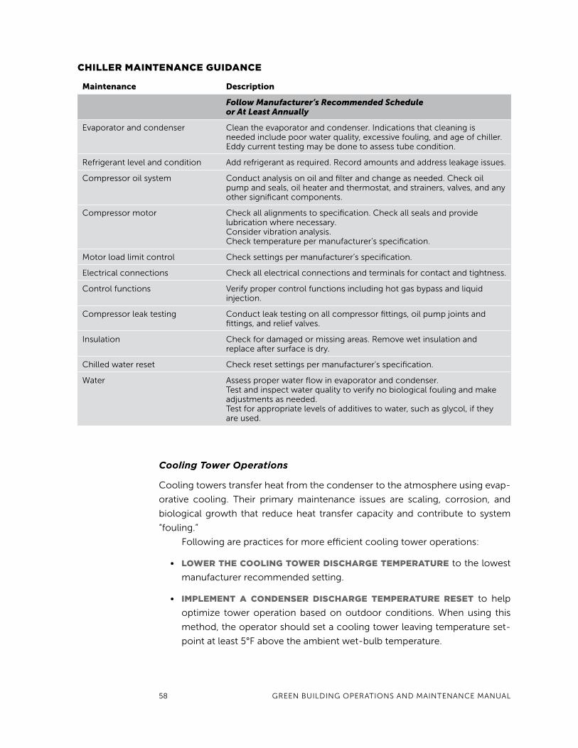
cHILLer MaIntenance guIdance
Maintenance Description
Follow Manufacturer’s Recommended Schedule or At Least Annually
Evaporator and condenser Clean the evaporator and condenser. Indications that cleaning is needed include poor water quality, excessive fouling, and age of chiller. Eddy current testing may be done to assess tube condition.
Refrigerant level and condition Add refrigerant as required. Record amounts and address leakage issues.
Compressor oil system Conduct analysis on oil and filter and change as needed. Check oil pump and seals, oil heater and thermostat, and strainers, valves, and any other significant components.
Compressor motor Check all alignments to specification. Check all seals and provide lubrication where necessary. Consider vibration analysis. Check temperature per manufacturer’s specification.
Motor load limit control Check settings per manufacturer’s specification.
Electrical connections Check all electrical connections and terminals for contact and tightness.
Control functions Verify proper control functions including hot gas bypass and liquid injection.
Compressor leak testing Conduct leak testing on all compressor fittings, oil pump joints and fittings, and relief valves.
Insulation Check for damaged or missing areas. Remove wet insulation and replace after surface is dry.
Chilled water reset Check reset settings per manufacturer’s specification.
Water Assess proper water flow in evaporator and condenser.test and inspect water quality to verify no biological fouling and make adjustments as needed.test for appropriate levels of additives to water, such as glycol, if they are used.

HVAC In tHE SOUtHEAStERn ClIMAtE REGIOn 59
• cLose tHe ByPass vaLve Before startIng tHe cooLIng-tower
fans to avoid short-circuiting of hot water returning directly back to the
chiller, which would lower chiller efficiency.
• use tHe trend-LoggIng caPaBILIty of tHe dIrect dIgItaL con-
troL (ddc) to track the temperature of the water leaving the tower. High-
er than normal temperatures may indicate that the tower is not operating
properly.
Cooling towers create environments conducive to biological growth.
Pathogenic organisms such as Legionella Pneumophila (legionnaires’ disease)
can develop in circumstances where the water is warm (95–99°F) and has a high
concentration of minerals. Although awareness of this issue has helped reduce
the incidence of sickness from cooling towers, locating outdoor air intake vents
far from the cooling tower plumes is critical to avoid entrainment of these
pathogens into ventilation air.
the most common treatments for scaling, corrosion, and biological/bacte-
rial growth are the use of chemical additives and significant over-use of water.
Most system operators use chemical biocides to inhibit biological growth, and
allow a significant amount of “blow down” or deliberate water overflow to intro-
duce fresh water into the system, thereby reducing the concentration of con-
taminants and the buildup of scale. these water treatment practices, however,
can have significant impacts on the environment and should be considered and
implemented carefully.
Blow down helps clean the tower, but should be limited since it requires
more make-up water. In addition, spillage transports chemicals, such as chlo-
rides, chromates, corrosion inhibitors, high concentrations of sulfides (if the
water is treated for pH), and elevated concentrations of salt, into the external
environment.
there are a number of alternative options to chemical treatment of water;
however, they tend to require additional investments in the chilled water system.
Ozone treatment and mechanical cleaning are two viable alternatives to the
use of chemical biocides. Both have advantages and disadvantages, and both
can have high initial costs. Ozone treatment has a higher first cost, but it lowers
lifecycle costs and water consumption. the labor costs for both chemical and
ozone systems are about the same. Ozone may be the best option in municipali-
ties with strict blow down water disposal regulations.

60 GREEn BUIlDInG OPERAtIOnS AnD MAIntEnAnCE MAnUAl
Refer to the Operations and Maintenances Best Practices Release 3.0 guide,
available through the DOE website, for more information on operating and main-
taining efficient cooling plants.
Heating systems
Heating systems commonly used in public housing in the Southeast include elec-
tric resistance heat; heat pumps; gas furnaces; and central steam, hot water, and
radiator space heating systems. Each system is discussed with general guidance
on operations followed by a maintenance guidance chart. Central steam and hot
water have more components requiring specific maintenance, so some of these
components have maintenance guidance charts of their own.
cooLIng tower MaIntenance guIdance
Maintenance Description
Daily
Overall visual inspection
Complete overall visual inspection to be sure all equipment is operating and that safety systems are in place.
Weekly
Vibration Check for excessive vibration in motors, fans, and pumps.
Fan motor condition Check the condition of the fan motor through temperature or vibration analysis and compare to baseline values.
Check belts and pulleys Adjust all belts and pulleys as needed.
Check tower structure Check for loose fill, connections, leaks, etc.
Clean suction screen Physically clean screen of all debris.
test water samples test for proper concentrations of dissolved solids, and chemistry. Adjust blow down and chemicals as necessary.
Operate make-up water float switch
Operate switch manually to ensure proper operation.
Monthly
Check lubrication Ensure all bearings are lubricated per the manufacturer’s recommendation.
Check motor supports and fan blades
Check for excessive wear and secure fastening.
Motor alignment Align the motor coupling to allow for efficient torque transfer.
Check drift eliminators, louvers, and fill
look for proper positioning and scale buildup.
Annually
Clean tower Remove all dust, scale, and algae from tower basin, fill, and spray nozzles.
Check bearings Inspect bearings and drive belts for wear. Adjust, repair, or replace as necessary.
Motor condition Check the condition of the motor through temperature or vibration analysis to ensure long life.
HVAC In tHE SOUtHEAStERn ClIMAtE REGIOn 61
Electric Resistance Heat
Electric resistance heat is the simplest but least efficient type of heating system,
and may be found in the form of either baseboard or forced-air electric resis-
tance heat.
Baseboard Heating Operation
Units located on exterior walls along the baseboards are known as “baseboard”
heating units and rely on convection and radiation to transfer heat. they do not
rely on air distribution fans and have little to maintain. Solid furniture should not
be placed in front of baseboard heaters since doing so will limit both convective
and radiative heat exchange to the room and create uneven space temperatures.
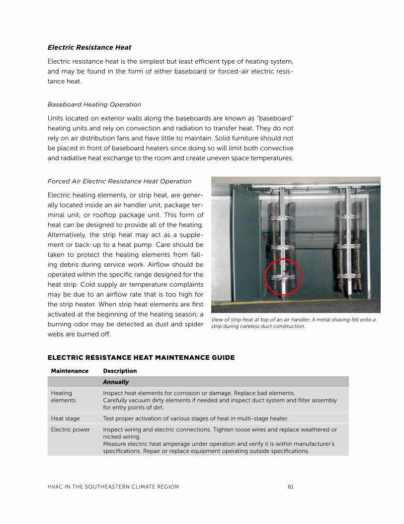
Forced Air Electric Resistance Heat Operation
Electric heating elements, or strip heat, are gener-
ally located inside an air handler unit, package ter-
minal unit, or rooftop package unit. this form of
heat can be designed to provide all of the heating.
Alternatively, the strip heat may act as a supple-
ment or back-up to a heat pump. Care should be
taken to protect the heating elements from fall-
ing debris during service work. Airflow should be
operated within the specific range designed for the
heat strip. Cold supply air temperature complaints
may be due to an airflow rate that is too high for
the strip heater. When strip heat elements are first
activated at the beginning of the heating season, a
burning odor may be detected as dust and spider
webs are burned off.
View of strip heat at top of an air handler. A metal shaving fell onto a strip during careless duct construction.
eLectrIc resIstance Heat MaIntenance guIde
Maintenance Description
Annually
Heating elements
Inspect heat elements for corrosion or damage. Replace bad elements.Carefully vacuum dirty elements if needed and inspect duct system and filter assembly for entry points of dirt.
Heat stage test proper activation of various stages of heat in multi-stage heater.
Electric power Inspect wiring and electric connections. tighten loose wires and replace weathered or nicked wiring.Measure electric heat amperage under operation and verify it is within manufacturer’s specifications. Repair or replace equipment operating outside specifications.

62 GREEn BUIlDInG OPERAtIOnS AnD MAIntEnAnCE MAnUAl
Heat Pump Operation
A heat pump is an air conditioner
that can also operate in a reverse
cycle to provide space heat. to
achieve this, a reversing valve
allows the refrigerant to flow in
the opposite direction. In heating
mode, the outdoor coil becomes
the evaporator, discharging cold air
outdoors; the indoor coil becomes
the condenser, discharging hot air
indoors (see Figure 3).
Heating provided by heat
pumps is about 2.5 to 3.5 times the
efficiency of electric resistance strip
heat, depending upon the outdoor
temperature. the efficiency and
capacity of a heat pump declines
as outdoor temperature decreases.
So, while a heat pump can still heat
at 25°F, it does not deliver as much heat as when it is 40° outside. For this reason,
heat pumps have strip heat available for especially cold periods. note that adjust-
ing the heating setpoint by 2 degrees or more will activate the strip heat, which
can lead to considerable energy waste. this problem is avoided by programming
the thermostat to disable the strip heat above a specific outdoor temperature.
If the thermostat does not have that capability, an outdoor thermostat can be
installed to serve the same purpose.
Heat Pump Maintenance Guidance
Maintenance of the heat pump air handler will be the same as that performed for
maintenance of AHUs (see AHU section below). Maintenance of the heat pump
outdoor unit is similar to condensing units.
Heat transfer relies upon the coil surfaces remaining fairly clean. therefore,
the outdoor coil must be protected from anything that interferes with airflow
around and through it. this includes snow and ice. Elevating the outdoor heat
pump unit four to eight inches above the surrounding grade will help keep snow
from blowing up to and settling against the coils. Snow fence material can also
be installed around heat pumps to protect them from wind driven snow during
storm events.
fIgure 3. Heat PuMP oPeratIon In wInter1) compressor 2) reversing valve 3) condenser 4) evaporator

HVAC In tHE SOUtHEAStERn ClIMAtE REGIOn 63
Gas furnace with panel removed. Cabinet and return duct leakage can interfere with natural draft appliances such as the gas water heater at left.
Heat PuMP MaIntenance guIdance
Maintenance Description
Annually
Outdoor coil Clean the outdoor coil and remove any debris such as leaves or dirt from around or near the outdoor unit. Repair damaged fins.Keep snow and ice cleared away and make sure defrost water melt can drain away from the unit without harming building.DO nOt attempt to forcefully remove ice build up from any part of the heat pump. Do use the cooling cycle or warm water to melt ice build-up.
Refrigerant leaks Inspect tubes and coil for evidence of leaks. Have a leak test done and seal leak on system that requires refrigerant to be added.
Fan lubricate fan motor bearings according to manufacturer’s recommendation.Inspect fan for damage or unusual vibration or noise. tighten and adjust fan mounts as needed.
Electric power Inspect wiring and electric connections. tighten loose wires and replace weathered or nicked wiring.Measure heat pump amperage under operation and verify it is within manufacture specifications. Repair or replace equipment operating outside specifications.
Gas Furnace Operation
PHA buildings commonly use gas furnaces for space heating. Any space where
gas combustion appliances such as a furnace or water heater are located is
referred to as a combustion appliance zone (CAZ). A gas furnace consists of a
metal cabinet, combustion components, and an internal fan to circulate heated
air to the building. Furnace maintenance should focus on 1) fuel delivery, 2) fuel
ignition and combustion, 3) heat transfer to air, and 4) combustion venting.
When properly installed and maintained, these furnaces operate safely. However,
problems related to any one of these four processes can result in unhealthy and
sometimes lethal consequences.
Some considerations related to safe furnace operations include the
following:
• PILot LIgHt: Older furnaces have a pilot light that ignites gas once the gas
valve opens. the pilot light should burn blue at the inner core of the flame
and should also surround the thermocouple, causing it to glow red. A pilot
light that has to be lit often may be a sign of building airflow imbalance. A
building science expert familiar with unbalanced airflows and combustion
systems should evaluate this circumstance.
• eLectronIc IgnItIon: newer furnaces have an electronic ignition that
generates a spark to ignite fuel. the igniter should be aligned properly at
the front of the burner. Furnaces with electronic ignition that fails to ignite
after several attempts will go into a soft lock-out and will prevent further
attempts to activate. Units that lock out often should be inspected by a
qualified technician.

64 GREEn BUIlDInG OPERAtIOnS AnD MAIntEnAnCE MAnUAl
• coMBustIon cHaMBer: Once the gas ignites, it
burns inside the combustion chamber. the flame
should appear blue. Improper air-to-gas ratios pro-
duce yellow in the flame. Inspections should also look
for sooty areas within the combustion chamber.
A qualified service technician should service the
unit if evidence of soot or yellow flame is observed.
Complete combustion requires an adequate amount
of air. In many cases, dilution air is also required. this
dilution air enters the atmospheric vent and flows out
of the building along with the combustion gases to
dilute the combustion byproducts and reduce mois-
ture condensation in the vent. Vent openings are pro-
vided into the combustion appliance zone in order
to provide the required combustion air and dilution
air. these combustion/dilution vent openings should
comply with the national Fuel Gas Code, known as
standard nFPA 54, and applicable codes, and should
be inspected periodically to verify that no blockage
has occurred.
• storage: As a safety precaution, the building policy
should prohibit storage in either mechanical rooms
or mechanical closets that contain combustion
appliances.
• Heat excHange: Heat is transferred from the com-
busted gas through the heat exchanger located inside
the furnace. Generally, the heat exchanger requires
no maintenance. However, older systems should be
inspected for cracks that could allow carbon mon-
oxide (and other combustion gases) to enter into the
building.
• vents: Combustion gas is vented to the outdoors
through a vent. Older systems often use a natural
draft (or atmospheric draft) vent to carry the combus-
tion gases outdoors. the buoyancy force of natural
draft can easily be overcome by space depressuriza-
tion (caused by exhaust fans, return duct leakage, or
AHU leakage), resulting in air quality problems such
as spillage, backdrafting, or, in severe cases, flame
rollout. Higher efficiency furnaces have fan-powered
exhaust since the exhaust temperature is cooler and
the draft strength is lower than natural draft. More
Furnace electronic igniter glowing brightly just before fuel is delivered.
Light blue flames indicate clean efficient combustion.
Three flames with varying fuel to oxygen ratio. The very yellow flame at far left needs more oxygen and will produce carbon monoxide and fine soot particles. The middle flame has improved oxygen supply, but still needs to produce complete combustion. The flame on the right produces clean and efficient combustion with no visible yellow and a clear blue tip.
yellow
violet
blue

HVAC In tHE SOUtHEAStERn ClIMAtE REGIOn 65
Central Steam, Hot Water, and Radiator Space Heating
System Operations
Central steam and hot water systems are commonly used in large public hous-
ing buildings. In simple terms, these systems consist of a boiler that heats water
and piping to distribute hot water or steam to radiators located in areas to be
heated. the system also has piping that returns the cooler water or condensed
steam back to the boiler. In most hot-water systems, pumps move the hot water
gas furnace MaIntenance guIdance
Maintenance Description
Monthly or As Needed
Combustion/ dilution air
Verify proper clearance of objects from vents that admit combustion/dilution air into the space.
Air filters Inspect and change as needed.
Motors and fans tighten belts and lubricate bearings.
Combustion Inspect ignition, pilot light, and burner flame. Verify effective exhaust.
Annually Prior to Heating Season
Ignition Inspect pilot light for proper flame and that the thermocouple sensor is within the pilot light. Consider having a building science expert determine if frequently blown out pilot lights are caused by zone depressurization. Inspect electronic igniters to verify proper ignition. Have qualified service technician determine causes of ignition problems.
Combustion Inspect flames in burners for clear blue flame absent of yellow. Service technician should be used to adjust and clean equipment if yellow flame, soot, or oversized or undersized flames are observed.Inspect combustion vents for damage or blockage. Repair as needed and in compliance with nFPA54.Using a gas leak detector, determine if fuel leakage is occurring at valves and fittings.
natural draft exhaust Inspect combustion exhaust vent for damage or blockage. A smoke puffer can be used to verify complete draft up natural draft exhaust vents with the unit operating. Smoke that wafts or “blows” back into space from the entry of the vent indicates incomplete draft, also known as spillage.
Powered draft exhaust
Ensure that the fan operates quietly. Combustion vent duct should be tightly connected to the fan. Perform inspection to verify that the combustion vent is not damaged, leaking, or blocked.
Heat exchanger Inspect for a cracked heat exchanger by observing for flame modulation or yellow flame. Heat exchanger should be replaced if cracked. Carbon monoxide can be detected in the central air distribution system (after the heat exchanger) if there is a crack in the exchanger.
lubrication Ensure all bearings are lubricated per the manufacturer’s recommendations.
Motor supports Check for excessive wear, secure fasteners, and adjust alignment if needed.
Belts Adjust belts and replace worn or damaged belts.
details on combustion safety can be found in the Health and Safety section
of this chapter.

66 GREEn BUIlDInG OPERAtIOnS AnD MAIntEnAnCE MAnUAl
from the boiler to individual radiators. thermostats modulate the flow rate of hot
water or steam to individual spaces. the boiler burner is activated as needed to
maintain an internal boiler temperature, which may be reset based on outdoor
temperature.
Distribution Piping Operation
Pipes circulate heated water or steam through the building. Insulate the distribu-
tion pipes (especially where the pipes run through unconditioned spaces), and
inspect the insulation at least annually or after any service that disrupts insulation.
Insulation should not be compressed or have gaps between sections. Replace
missing or damaged sections. Address dripping from pipes immediately. Discard
and replace wet insulation after pipe surfaces have been repaired and dried.
Infrared cameras or spot thermometers can be useful in finding areas that need
replacement.
Boiler Operation
Boilers come in different sizes and styles, but all are designed to provide hot water
or steam. Boilers are typically either water-tube or fire-tube style. Relatively small
boilers operate fairly simply and do not require as much maintenance as large
boilers with more complicated systems and controls. In fact, some of the infor-
mation covered here may not apply to small hot water (also known as hydronic)
heating systems.
Keeping daily records of boiler operation is important to boiler main-
tenance. As a baseline, measure fuel consumption, flue gas temperatures, and
water pressures and temperatures during periods when equipment is known to
operate as expected. the baseline allows the operator to identify substandard
performance and take corrective action before larger problems develop. For ex-
ample, flue gas temperatures that gradually increase over a period of time could
signal a build-up of scale, reduced capacity, and diminished efficiency. Keeping
the system clean helps maintain efficiency, durability, and reliability.
Maintenance and operations can affect boiler efficiency, according to the
EPA report Wise Rules for Industrial Energy Efficiency:
• Optimizing air-to-fuel ratio, burner maintenance, and tube cleaning can
save about 2% of a facility’s total energy use with an average simple payback
of 5 months.
• tune-ups using precision testing equipment to detect and correct excess
air losses, smoking, unburned fuel losses, sooting, and high stack tempera-
tures can result in boiler fuel savings of 2–20%.
• Boiler fuel use can be reduced 1–2% for each 40°F reduction in net stack
temperature (outlet temperature minus inlet combustion air temperature).

HVAC In tHE SOUtHEAStERn ClIMAtE REGIOn 67
• Removing just a 1/32-inch deposit on boiler heat transfer surfaces can de-
crease a boiler’s fuel use by 2%.
• For every 11°F that the entering feedwater temperature is increased, the
boiler’s fuel use is reduced by 1%.
Water Quality in Boiler Maintenance
Municipal water has dissolved minerals, oxygen, and chemicals that can shorten
the life of a boiler. Water chemical treatment and softeners are important ele-
ments of boiler maintenance to remove dissolved solids and hardness. Deaerators
remove oxygen from feedwater to protect the boiler from pitting and corrosion.
In a boiler steam system operating below 300 psi, it is recommended that feed-
water have less than 3500 PPM total dissolved solids, maximum alkalinity of
700 ppm, and hardness less than 20 ppm.
the blowdown system is designed to remove larger pieces of sediment from
the boiler. In steam systems, the condensate return unit captures condensed
steam to be used again. this conserves water and treatment chemicals, and pre-
vents chemical discharge to the city sewage system. Make-up water should be
supplied by nonpotable sources when possible. this would require a catchment
system to collect precipitation that can be delivered into the feedwater.
Combustion Equipment
Take care to maintain the combustion part of the boiler. The air and gas must
not only be in correct proportion, but also properly mixed to ensure complete
combustion. Gas pressure is controlled through a pressure regulator, and a fan
controls the volume of combustion air. Combustion fan problems can seriously
affect combustion efficiency. Excessive fan noise or vibration is an indication of
worn or damaged parts.
Some possible causes for inadequate combustion air:
• Incoming air limited by poorly adjusted dampers or inlet vanes
• Fan inlet or outlet is obstructed
• Air leaks within the system
• Damaged blower wheel or bearings
• Worn or broken fan mount.
the table below provides general guidance for boiler maintenance. the
DOE Federal Energy Management Program document O&M Best Practices
Guide, Release 3.0 is a good resource for details on boiler maintenance practices
and inspection logs.

68 GREEn BUIlDInG OPERAtIOnS AnD MAIntEnAnCE MAnUAl
BoILer MaIntenance guIdance
Maintenance Description
Daily
Water level Inspect water level, test low water cut off. Consider metering feedstock water since this can help determine if system performance is dropping.
Blowdown Perform blowdown to maintain clean boiler operations.
Visual inspection and record keeping
Make note of:Operating boiler pressure and temperatureFeedwater pump operationFeedwater pressure and temperatureCondensate temperatureFlue gas temperatureGas pressureOil pressure and temperature
Inspect combustion Inspect the burner operation, look for signs of poor combustion such as soot, yellow flames, or over- or under-sized flames.
Bi-Annually
Refractory Clean and vacuum fireside surfaces as required.Inspect refractory for large cracks or missing pieces. Patch and wash coat as required.Inspect gasketing on doors and replace as needed.
tubes Inspect for soot deposits, pitting or deposits.Sooting can be an indication of a burner that needs adjustment. Pitting can be a sign of condensation of flue gas, which can occur due to short firing cycles. Increasing water temperature can produce longer cycles. White deposit on the ends of tube sheet can be a sign of leaks. A boiler service company may need to re-roll tubes.
Boiler / feedwater Flush boiler with water to remove loose scale and sediment as needed.Check all hand hole plates and manhole plates for leaks at normal operating temperatures and pressures.Open feedwater tank manway, inspect and clean as required.
Combustion Clean burner and burner pilot.Check pilot electrode and adjust or replace as needed.Clean air damper and blower assembly.Clean motor starter contacts and check operation.Make necessary adjustments to burner for proper combustion and record all results in service report.Perform all flame safeguard and safety checks and record results in service report.
Controls Clean and inspect low water cut off controls. Remove plugs in control piping; inspect, clean and re-install.
Water treatment Inspect chemical treatment tanks and pipes for leakage. Check water for proper quality per manufacturer recommendations.
Condensate return Inspect condensate return pumps for leakage; inspect motor and measure motor amps.
Annually
Blowdown piping Inspect piping for obstructions.
Boiler tubes Clean at least once a year or more often if needed.

HVAC In tHE SOUtHEAStERn ClIMAtE REGIOn 69
Radiator Operation
the radiator transfers heat from the hot water or steam to the conditioned space.
Some important things to address for good radiator operations include:
• traPPed aIr In a Hot water systeM: Over time, air can enter a hot
water system, decreasing system efficiency, and should be removed.
• traPPed water In a steaM systeM: A banging sound as the radiator
begins to heat is a sign of trapped water in a steam system. Steam radia-
tors should have appropriate tilt to allow all condensed water to drain. tilt
should be toward the drain in a one-pipe system and toward the steam trap
in a two-pipe system.
• steaM traP: A steam trap that needs to be replaced may cause poor tem-
perature control.
• InsuLatIon: Placing insulation or reflective surface behind the radiator will
minimize the heat loss to outside. the reflective surface should be durable
and cleanable.
• vents: Steam radiator vents should also be maintained. Vents allow air in
the radiator to exit as steam comes into the radiator. they should close once
steam reaches the vent. Failure to close properly results in a loss of steam
into the space, which can result in overheating of space and wasted energy.
Prolonged whistling or air noise indicates that a vent should be cleaned or
replaced.
radIator MaIntenance guIdance
Maintenance Description
Annually or As Needed
Hot water system water level
Bleed air from radiators in hot water systems before the heating season begins.
Zone control Verify that zone controls work by manipulating thermostats and observing appropriate valve control response.
Steam radiator mounting
Verify proper tilt for draining condensate back to boiler.
Steam system air vents
Inspect vents during operation to verify the close properly and do not allow steam to escape.Clean or replace as needed.
Heat reflector surface
Clean reflective surfaces located behind radiators and secure loose mounts as needed.
Steam Trap and Valve Operation
As steam enters the radiators and releases heat into space, some water vapor con-
denses into water that must be removed from the steam system. Steam traps are

70 GREEn BUIlDInG OPERAtIOnS AnD MAIntEnAnCE MAnUAl
devices that allow condensed steam (condensate) to be released without releas-
ing steam. Some systems release the hot water to a drain, which wastes water
and energy resources. In contrast, better designed systems pipe the condensate
back to a collection point to use as feedwater as needed.
Control valves are used to limit water or steam flow, and pressure relief
valves maintain safe operating pressures. Various types of valves used in the wa-
ter or steam distribution system rely on seals that can become worn over time
and develop leaks.
the DOE reports that facilities lacking advanced steam plant maintenance
programs can lose 20% of the steam generated through leaking steam traps (typ-
ically located in unconditioned space so that lost energy escapes to outdoors).
Even small losses of steam should be taken seriously because so much energy is
required to change water to steam. Programs that use the best equipment and
programs can reduce steam leak losses to less than 1%.
steaM traP and vaLve MaIntenance guIdance
Maintenance Description
Daily
High pressure steam traps (>250 psig)
Inspect for steam leakage. Short inspection interval is recommended since large quantities of steam can be lost at high pressure traps. Clean or repair as needed, replace when cleaning is no longer effective or about every 3-4 years. Verify that replacement traps are proper trap size.
Pressure relief valves Inspect for chattering or water leaking. Repair seals or replace valves as needed. Valves rarely utilized in well-maintained systems may last several years before requiring replacement.
Weekly
Pressure traps operating between 30-250 psig
Inspect for steam leakage. Clean as needed, replace when cleaning is no longer effective.
Monthly
Pressure traps operating below 30 psig
Inspect for steam leakage. Clean as needed, replace when cleaning is no longer effective.
air distribution systems
In most buildings, HVAC is distributed by means of an air distribution system
(ADS). the intended goal of the ADS is to deliver air to various spaces in order
to maintain desired temperature, RH, and air freshness. the ADS includes fans
to move air, heating and cooling systems to condition the air, outdoor air and
exhaust systems to control air exchanges with outdoors, and filters to control

HVAC In tHE SOUtHEAStERn ClIMAtE REGIOn 71
particulate levels in the air. this section first discusses background and issues,
then covers operations and maintenance priorities.
Background and Issues
Poorly designed or maintained air distribution systems also produce unintended
effects. For example, air distribution leakage can diminish the heating and cool-
ing capacity of the system, increase energy use, and cause poor indoor air quality.
Duct Leakage
Duct leakage is a large problem in commercial buildings. One study found air
leakage from commercial building ducts to be 70 times greater than the Sheet
Metal and Air Conditioning Contractors national Association (SMACnA) standard
for duct air-tightness. If the ducts are located outside the air and thermal bound-
ary of the building, then these leaks create large energy losses. they also create
unbalanced airflows, which produce positive or negative building pressure, which
in turn moves air across the building envelope air boundary. If the duct leakage
occurs inside the building air and thermal boundaries, then the effects of energy,
airflow balance, and space pressure are greatly muted. Even relatively small por-
tions of the air distribution system, such as the AHU, can have significant impacts
on duct leakage. this can happen even if the rest of the duct system is very tight.
One study of 69 AHUs in Florida found that more than 4% of the total system
airflow was leaking into the cabinet of the AHU. leaks in the AHU cabinet may be
relatively small in terms of surface area, but because the operating pressures in
the AHU are large, the resulting air leakage into the unit may be quite large.
leakage in the ventilation ductwork can also occur. the air that leaks into
outdoor air ducts from within the building air boundary diminishes the amount
of “fresh” ventilation air, and may also draw contaminated air from attics, crawl
spaces, and basements into the building. In the case of exhaust duct leakage,
keep in mind that poorly conducted test and Balance may add to the problem:
• the air drawn from the building through leaks will add to total building
ventilation, but will not show up in measurements of exhaust at the grills.
• test and Balance will typically measure exhaust only at the exhaust grills;
therefore, part of their HVAC adjustments may increase total exhaust fan
flow rates to achieve the target airflows at the grills.
• As a result, the building may become more depressurized as a result of test
and Balance work.

72 GREEn BUIlDInG OPERAtIOnS AnD MAIntEnAnCE MAnUAl
Unexpected Interactions
there can sometimes be other unexpected interactions between features of the
ADS. For example:
• LocatIon and tyPe of aIr fILters: the location and type of filters
can affect both the quantity and consequences of duct leakage. Air filters,
which are typically intended to keep ducts, coils, and fans clean, are typi-
cally located at either the AHU or at grills. If filters are located at return grills,
the return ductwork will operate under greater levels of negative pressure.
Greater negative pressure, in turn, causes greater airflow through the re-
turn leak openings. Additionally, the air leaking into the return ductwork
can carry dust into the system, which will not be filtered because the filter
is upstream of the leak sites. By contrast, if the filter is located at the AHU,
then the return ducts will be less depressurized, less return leakage will oc-
cur, and the dust entering those leaks will be filtered as it enters the AHU.
Overall it is best to have a tight duct system with filtration at grills to keep
the return duct cleaner.
• return aIr IMBaLance: Some buildings experience return air imbalance,
which occurs when the amount of return drawn from a zone is greater
or less than the amount of supply air delivered to that zone. this is es-
pecially common in buildings where the return(s) are located in the cen-
tral space while supply air is delivered to rooms that can be closed. When
doorways between the interior spaces are closed, the return versus sup-
ply imbalance can create either negative or positive pressure in that space,
and this pressure can in turn move air across the building envelope. Unbal-
anced return air can increase the building infiltration rate and, during hot
and humid weather, can increase indoor RH. In some cases, space depres-
surization can cause moisture and mold problems in wall or other inter-
stitial cavities. In other cases, this depressurization can cause combustion
safety problems (see the Health and Safety section below).
Improve unbalanced return air by either adding ducted return air to each
space that has a door and supply air, or by installing air transfer pathways
from the closable room to the central space where return air is located.
transfers may be simple grills through a wall or door. Another method of
transfer is to install a short section of duct in attic or ceiling space. the
transfer duct is connected to a grill in the room ceiling with the other end
connected to a grill in the central space ceiling.
In some cases, the amount of supply air delivered to a space is not propor-
tional to the heating or cooling loads. this can lead to temperature variations and
comfort complaints.

HVAC In tHE SOUtHEAStERn ClIMAtE REGIOn 73
Air Distribution Systems Operations
Pressure Mapping
Pressure mapping can identify when the building or zones within it are operat-
ing at positive or negative pressure. this data can provide clues to duct leakage
or unbalanced return air. Pressure mapping involves measuring pressures from
one room compared to another. these measurements are made quickly using a
micromanometer with the AHU operating. Pressures across closed doors should
be less than 2.5 pascals (0.010 in WC).
Duct Air-tightness
Duct leakage is very common in light commercial buildings, such as PHA office
and common spaces, where it has been found to be about three times greater
than in residences. testing for duct system air-tightness can be useful to under-
stand the performance of HVAC systems and to correct energy waste. It can
also help to understand high building infiltration rates or large building pressure
differentials. A thorough duct tightness evaluation will involve a tightness test as
well as visual inspection. the tightness test uses a special fan to depressurize the
duct system to 25 pascals of pressure. the leakage airflow is measured as cubic
feet per minute (CFM) at 25 pascals, so the test result is often noted as CFM25.
Most ductwork in public housing would fall under the lower pressure classifica-
tions typically used in small commercial and residential construction.
A good duct tightness goal for existing ducts in public housing common
spaces should be about 0.05 CFM25/cfm of rated airflow. this would be total
leakage of the system divided by the maximum rated airflow of the air handler
unit on the duct system being tested. this goal can also be stated as follows:
The total duct leakage, CFM25, should not exceed 5% of the maximum rated
airflow (cfm) of the heating/cooling system being tested. It may be difficult for
some systems to reach this goal if the duct system has limited access that pro-
hibits sealing portions of the ducts. Visually small seams and cracks do not ap-
pear as significant leaks, and it can even be hard to feel leakage, but they may
also have to be sealed to meet a 5% leakage goal.
to improve duct air-tightness:
• Start a visual inspection at the AHU.
• Inspect and seal seams, holes, and penetrations in the AHU cabinet.
• Pay special attention in reinstalling filter access panels after changing filters
because such an opening can easily lead to serious depressurization of the
mechanical room and perhaps cause backdrafting of combustion appliances.
• Inspect every connection and seam at least once, or after any duct alteration.
74 GREEn BUIlDInG OPERAtIOnS AnD MAIntEnAnCE MAnUAl
• Seal connections with duct mastic according to SMACnA and north
American Insulation Manufactures Association (nAIMA) standards.
Cooling and heating energy savings can vary depending on how much of
the duct system is within the air and thermal boundaries of the building. Even
duct systems within conditioned space should be reasonably tight to ensure bet-
ter air quality control. tighter ducts can result in energy savings from reduced fan
power in variable air volume systems.
Filtration
Inspect filters regularly. Replace or clean filters when visual inspection indicates
dirt build-up, or based on pressure drop across the filters, or on a pre-arranged
schedule. In general, avoid replacing filters before they become dirty because
this puts additional load on landfill. Filtration efficiency is classified by Minimum
Efficiency Report Value or MERV. Generally, use filters with MERV ratings in the
range of 5 to 8.
Filters located at the return grills will cause the ductwork to operate under
a higher level of depressurization. leaky return ductwork will not only lead to in-
creased levels of air leaking into the ADS, but also the unintended airflow will be
unfiltered. this entry of dust and particulates can lead to fouling of the heating
or cooling coils, and of the ADS interior surfaces. this can foster the growth of
mold within the ADS.
Temperature and RH Logging
Indoor temperature and RH can be tracked with logging devices. these logging
devices are relatively inexpensive and yet provide powerful diagnostic assess-
ment. the collected data identifies patterns of temperature or RH that can iden-
tify system performance problems.
temperature and RH can be logged at returns and at supplies to identify
whether the heating or cooling system is providing conditioned air within per-
formance expectations. For example, the difference in temperature between the
supply air and return air should be approximately 18–20°F for an air condition-
er using direct expansion equipment. Measurement outside this range should
prompt further investigation of this system. Causes of low temperature differ-
ences can be related to improper refrigerant charge and return duct leakage.
Occasionally, improper thermostat connections made during service al-
low cooling equipment and strip heat to come on at the same time, resulting
in a difference of just a couple degrees between return and supply. Measuring
amperage of AHU would determine if the strip heat is activated.

HVAC In tHE SOUtHEAStERn ClIMAtE REGIOn 75
Other aspects to measure for potential improvements:
• test and BaLance tHe HeatIng and cooLIng systeMs: test and
Balance can be performed to characterize and make adjustments of airflow
rates to spaces and should be completed if no record exists or changes have
been made to the building or to its HVAC systems. System performance test-
ing can be a useful tool, especially for Dx air conditioning and heat pump
systems. Perform engineering calculations to convert the measured airflow
rates, return and supply temperatures, and supply and return RH into cool-
ing or heating capacity. Compare these calculated values to rated capacity
(taking outdoor temperatures into account) to help determine if servicing of
the units is warranted.
• test and BaLance tHe ventILatIon: test and Balance firms can also
measure the airflow rate of outdoor air and exhaust systems, to confirm
whether the required ventilation rates are being achieved. this should also
be done if there are no records of previous work or changes have been
made to the building or air distribution system. the best location to mea-
sure exhaust flows is where the airflow crosses the building envelope (e.g.,
at the roof). While this will not, in itself, verify that air is taken from each
space as designed, it will provide the total airflow from the building. testing
of the exhaust ductwork can determine if significant leakage exists.
• varIaBLe aIr voLuMe (vav) systeMs: With chilled water systems (and
some Dx systems), the AHUs are often VAV with duct static pressure con-
trol. Individual VAV boxes adjust supply airflows to the spaces they serve to
maintain the desired space temperature. the speed of the AHU fan is ad-
justed based on measurement of static pressure in the main duct. When VAV
box dampers open to provide more heating or cooling, the AHU fan speed
is increased to maintain this static pressure. Achieve energy savings by tun-
ing the operation of the VAV boxes and implementing static pressure reset
(e.g., lowering the duct pressure setpoint when airflow needs are reduced).
Calibrate the static pressure control and inspect the VAV box damper con-
trol annually. Maintenance should include inspection for poor connections
or cracked tubes of tubing connected to pressure sensors.
76 GREEn BUIlDInG OPERAtIOnS AnD MAIntEnAnCE MAnUAl
aIr dIstrIButIon systeM cHeckLIst
1. PeRfoRM PReSSuRe MAPPinG when any modifications affecting system airflow or distribution are made to
the HVAC system, to the building envelope, or to interior partitions. Measure building pressure with the outdoor
air (OA) normally open and with it sealed off, and with the AHUs on and off.
• If the building or spaces within the building are found to be operating at negative pressure, look into
the causes of these pressure differentials, including duct leakage, unbalanced return air, and exhaust fan
operation.
2. PeRfoRM DuCt leAkAGe teStinG, if it has never been done or after any HVAC duct modifications,
especially:
• if the ductwork is located outside the building air and thermal barrier,
• if visual inspection yields suspicion of duct air leakage,
• if pressure mapping finds the building pressure changing when the AHUs are turned on and the OA is sealed,
or
• if utility bills are larger than expected.
3. ARRAnGe foR leAky DuCtS to be SeAleD, using mastic and embedded fabric. Seal cracks, openings, and
penetrations in AHU cabinets.
4. inSPeCt filteRS on A ReGulAR bASiS (e.g., monthly). Replace or clean filters when visual inspection indi-
cates dirt build-up or based on pressure drop across the filters. Filters with MERV ratings in the range of 5 to 8
will filter well and limit static pressure increase. While filters can be replaced on a pre-arranged schedule, avoid
replacing filters before they become dirty because this wastes resources and puts additional load on land fill.
If filters are located at return grills, take steps to ensure that the return ductwork does not have significant air
leakage, since this can cause contamination of the ADS.
5. if HiGHeR MeRV filtRAtion iS ConSiDeReD, CHeCk DuCt StAtiC PReSSuRe to verify system opera-
tion is within the air handler manufacturer’s recommended values. If static pressure is too high, the filter surface
area may need to be increased. Filter surface area can be increased by going to a deep-pleated filter or fabricat-
ing a larger filter rack. Deep pleated filters have a higher first cost, but last longer and may have a lower lifecycle
cost.
6. ConSiDeR MeASuRinG SySteM AiRflow, as well as temperature and RH, at returns and supplies as needed
in zones with comfort complaints. This information can be used to characterize the performance of AC or heat
pump systems and indicate whether servicing of these systems is required.
7. ConSiDeR PeRfoRMinG teSt AnD bAlAnCe on tHe HVAC SySteMS:
• If significant changes are made to the HVAC systems (e.g., AHU replaced, ducts added, or new building addi-
tion),
• if pressure mapping finds significant pressure imbalances, or
• if comfort problems are reported and not easily remedied.
If airflows are found to be out of compliance with the design documents, make sure that these airflows are
properly adjusted.
8. witH VAV SySteMS, PeRioDiC CoMMiSSioninG of tHe AHu AnD VAV box ContRolS iS ReCoM-
MenDeD (e.g., every 5 to 10 years). Consider implementation of static pressure reset (which would be imple-
mented automatically through the building automation system when total heating or cooling load is reduced)
to achieve energy savings. Check dampers and linkages to ensure that intended airflows are achieved in re-
sponse to the automation system controls.
9. inSPeCt All ReGiSteRS foR ReStRiCtionS to AiRflow such as covers over supply vents or furnishings
placed in front of return or transfer grills.
HVAC In tHE SOUtHEAStERn ClIMAtE REGIOn 77
air Handler units
Air handler units (AHUs) distribute conditioned air and are available in a
wide range of sizes, depending upon the amount of air to be distributed
throughout a zone. An AHU consists of a metal cabinet and an electric
powered fan. the AHU may also contain cooling coils, heating coils, and
electric resistance heating elements. Classifications of air handling units
depend on where and how they are used. three types are commonly
used in PHAs:
• fan coIL unIt: this unit is simply a cabinet with a fan and a heat
exchange coil inside. Fan coil units are typically associated with
chilled water systems.
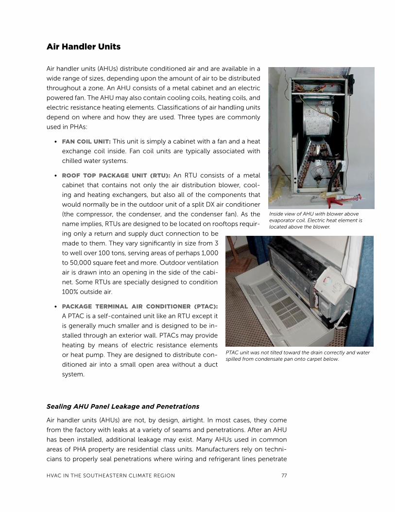
• roof toP Package unIt (rtu): An RtU consists of a metal
cabinet that contains not only the air distribution blower, cool-
ing and heating exchangers, but also all of the components that
would normally be in the outdoor unit of a split Dx air conditioner
(the compressor, the condenser, and the condenser fan). As the
name implies, RtUs are designed to be located on rooftops requir-
ing only a return and supply duct connection to be
made to them. they vary significantly in size from 3
to well over 100 tons, serving areas of perhaps 1,000
to 50,000 square feet and more. Outdoor ventilation
air is drawn into an opening in the side of the cabi-
net. Some RtUs are specially designed to condition
100% outside air.
• Package terMInaL aIr condItIoner (Ptac):
A PtAC is a self-contained unit like an RtU except it
is generally much smaller and is designed to be in-
stalled through an exterior wall. PtACs may provide
heating by means of electric resistance elements
or heat pump. they are designed to distribute con-
ditioned air into a small open area without a duct
system.
Sealing AHU Panel Leakage and Penetrations
Air handler units (AHUs) are not, by design, airtight. In most cases, they come
from the factory with leaks at a variety of seams and penetrations. After an AHU
has been installed, additional leakage may exist. Many AHUs used in common
areas of PHA property are residential class units. Manufacturers rely on techni-
cians to properly seal penetrations where wiring and refrigerant lines penetrate
Inside view of AHU with blower above evaporator coil. Electric heat element is located above the blower.
PTAC unit was not tilted toward the drain correctly and water spilled from condensate pan onto carpet below.

78 GREEn BUIlDInG OPERAtIOnS AnD MAIntEnAnCE MAnUAl
the cabinet. Relatively small holes or cracks may seem
too small to have much impact. However, since the
fan is located in the AHU, air pressure inside the AHU
cabinet is higher than at any other location in the air
distribution system. this powerful pressure differen-
tial can produce substantial air leakage through even
very small holes. Many AHUs have a draw-through
design, resulting in most of the cabinet under nega-
tive pressure, which means air leakage gets sucked
into the cabinet instead of blown out. Even new AHU
cabinets can leak about 4% of the total system airflow.
the energy penalty of this leakage varies con-
siderably depending upon the AHU location. If lo-
cated inside the building, these leaks may cause little
or no energy use increase. However, if located in an
attic, system efficiency from AHU cabinet leakage alone during the hot hours of
the day can decrease system capacity and efficiency by more than 10%.
this type of leakage can have three types of significant impacts:
• Increased energy waste: Depending upon unit location, AHU cabinet
leakage can increase cooling energy costs by 10% or more in hot and humid
climates.
• MoIsture condensatIon ProBLeMs: Moist air entering leaks can enter
the AHU cabinet and condense on cold surfaces. these moist areas may
damage equipment or support mold growth.
• Poor aIr quaLIty: Air leaking into the AHU cabinet carries unfiltered par-
ticles such as allergens, mold spores, and dust. these materials can build
up on surfaces inside the AHU, including the cooling coil, insulation ma-
terials, fan motor and blades, and condensate drain pan. this build-up of
dust and dirt can become the nutrient for mold growth, which can become
widespread inside of AHU cabinets. Air handling equipment in locations
such as garages, crawl spaces, attics, mechanical rooms, or shops will draw
any pollutant present in those spaces, including carbon monoxide, into the
conditioned space.
AHU cabinet leaks are generally easy and inexpensive to repair. Gasket ma-
terial is best to seal panel seams, since it should not have to be replaced every
time the access panels are opened. tape is a temporary alternative, as it will not
hold well when exposed to rain or extreme temperatures. tape adhesive also
leaves a grimy residue on panels and has to be replaced every time service panels
are opened. Penetrations should be sealed carefully using HVAC putty. While foil
tape can be used to seal panel seams, it does not effectively seal around wire and
pipe penetrations.
Roof top package unit leakage through loose panels.
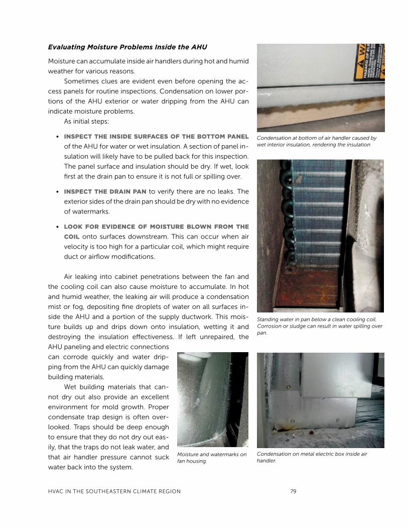
HVAC In tHE SOUtHEAStERn ClIMAtE REGIOn 79
Evaluating Moisture Problems Inside the AHU
Moisture can accumulate inside air handlers during hot and humid
weather for various reasons.
Sometimes clues are evident even before opening the ac-
cess panels for routine inspections. Condensation on lower por-
tions of the AHU exterior or water dripping from the AHU can
indicate moisture problems.
As initial steps:
• InsPect tHe InsIde surfaces of tHe BottoM PaneL
of the AHU for water or wet insulation. A section of panel in-
sulation will likely have to be pulled back for this inspection.
the panel surface and insulation should be dry. If wet, look
first at the drain pan to ensure it is not full or spilling over.
• InsPect tHe draIn Pan to verify there are no leaks. the
exterior sides of the drain pan should be dry with no evidence
of watermarks.
• Look for evIdence of MoIsture BLown froM tHe
coIL onto surfaces downstream. this can occur when air
velocity is too high for a particular coil, which might require
duct or airflow modifications.
Air leaking into cabinet penetrations between the fan and
the cooling coil can also cause moisture to accumulate. In hot
and humid weather, the leaking air will produce a condensation
mist or fog, depositing fine droplets of water on all surfaces in-
side the AHU and a portion of the supply ductwork. this mois-
ture builds up and drips down onto insulation, wetting it and
destroying the insulation effectiveness. If left unrepaired, the
AHU paneling and electric connections
can corrode quickly and water drip-
ping from the AHU can quickly damage
building materials.
Wet building materials that can-
not dry out also provide an excellent
environment for mold growth. Proper
condensate trap design is often over-
looked. traps should be deep enough
to ensure that they do not dry out eas-
ily, that the traps do not leak water, and
that air handler pressure cannot suck
water back into the system.
Condensation at bottom of air handler caused by wet interior insulation, rendering the insulation
Standing water in pan below a clean cooling coil. Corrosion or sludge can result in water spilling over pan.
Moisture and watermarks on fan housing.
Condensation on metal electric box inside air handler.

80 GREEn BUIlDInG OPERAtIOnS AnD MAIntEnAnCE MAnUAl
Cleanout caps should remain closed to avoid air rushing
into the drain line and restricting drain pan drainage. Open con-
densate lines act as a duct leak. In some draw-through type air
handlers, this air has high enough velocity to splatter water col-
lected in the drain pan onto interior surfaces. Maintenance pro-
grams should evaluate the traps to determine if modification is
needed. (For more information on air conditioning condensate
trap design, refer to an article in Heating/Piping/Air Condition-
ing Engineering Magazine at http://hpac.com/air-conditioning/
condensate_traps_brusha/)
One last thing to consider is where the air conditioning
condensation line ends. termination points should be located in
places that will not be exposed to toxic substances that could
adversely impact air quality in the event the trap becomes empty. Condensate
lines should never be terminated inside sewer lines, near combustion vents, or
near the ground where pesticides may be applied.
aIr HandLer MaIntenance guIdance
Maintenance Description
Weekly
Unit inspection Observe each unit to verify that it is operating as expected. Indications of problems should be recorded such as:• excessive vibration and uncharacteristic noise (squeak, rattle, hum), • loose access panels and unsealed cabinet penetrations, • surface condensation or dripping off of cabinet, and water leakage from the drain
pan.
Bi-Annually or As Needed
Vibration Immediately inspect systems with excessive vibration in motors and fans.
Fan motor condition If a problem with the fan motor performance is suspected, evaluate through temperature or vibration analysis compared to baseline values. Electric performance can also be measured using a power analyzer and compared to manufacturer specifications.
Check belts and pulleys
Adjust all belts and pulleys.
Bearing lubrication Ensure all bearings are lubricated per the manufacturer’s recommendation. Sealed bearings may not need maintenance. Elevated temperature at bearings is an indication of advanced wear.
Motor supports and alignment
Check for excessive wear, adjust and secure fastening as needed. Align the motor coupling to allow for efficient torque transfer.
Cabinet insulation Inspect the condition of insulation inside the air handler to look for damaged or missing sections. Check to see if insulation is wet and determine cause. Repair or replace insulation as needed.
Clean interior air handler, coil and fan blades
Inspect the interior of the AHU. Clean as needed. A good filtration program will keep equipment clean and minimize the need for time-consuming cleaning. If filters are located at the return grill, then dust entry may be occurring through return duct leaks. Consider repairing the return leaks or locating an additional filter in the AHU. Also make sure that outdoor ventilation air is filtered prior to entering the AHU.
A primary condensate trap (right) and secondary trap on a rooftop package unit.

HVAC In tHE SOUtHEAStERn ClIMAtE REGIOn 81
Maintenance Description
Inspect blower drive Inspect drive belts, pulleys, and bearings for wear. Adjust, repair, or replace as necessary. Some blowers are connected to a motor indirectly through a belt drive. lubricate unsealed bearings.
Cabinet leakage Check that panels fit tight with gaskets providing complete seal. Repair bent panels and replace damaged gaskets and missing screws. Make sure that filter access panels are put back into place and sealed tightly. All penetrations should be sealed.
Filter rack Carefully inspect filter rack to see that it holds all filters tightly in place with no gaps either between filter sections or around the filter rack assembly. Repair deficiencies that permit air to bypass filters. Replace filters according to schedule or alternatively based on static pressure across the filters. Replace when pressure target is reached.
Condensate Inspect drain pan for cracks or leaks. A system that properly drains condensate and is operated cleanly should not have the presence of sludge in the pan.Drain pan should slope towards drain and be free of any sludge. Clean and disinfect drain pan if there is evidence of microbial sludge. Flush out condensate drain traps and lines. Make sure the condensate drain line has a trap.Make sure traps are full of water and functioning properly.
Moisture inspection Inspect during hot and humid weather. the interior of the air handler should be dry, with the exception of the cooling coil and the drain pan.
Electric Verify that service power and control wire connections are tight.Replace wires that have damaged insulation jacket.Replace missing or damaged electric service cover plates.
ventilation
Ventilation is the process of intentionally moving air between the indoors and
outdoors to maintain acceptable indoor air quality. this section provides a fuller
understanding of the issues related to ventilating PHA common spaces.
Background and Issues
Outdoor air (OA) introduced through the central heating and cooling system
dilutes indoor contaminants and produces pressurization of the space. Exhaust
fans can capture air contaminants that are contained within a specific zone and
also dilute contaminants. they produce space depressurization. the require-
ments for ventilation for specific types of buildings are listed in building codes
and in applicable standards, such as ASHRAE Standard 62.1. Many jurisdictions
have adopted the requirements of the ASHRAE standard.
Air Infiltration
Infiltration, which can be understood as the unintended introduction of out-
door air into a building, can contribute to space ventilation. Infiltration can occur
either by means of natural infiltration (driven by the forces of wind or temperature

82 GREEn BUIlDInG OPERAtIOnS AnD MAIntEnAnCE MAnUAl
differential) or by mechanically driven forces (driven by duct leaks, unbalanced
return air, etc.). In most cases, infiltration cannot be counted on to provide reli-
able and predictable ventilation. Several types of tests, performed by trained
and qualified contractors, help the facility manager understand the amount of
air exchange that is occurring because of infiltration or from operation of the
ventilation systems:
• Blower door testing can measure the envelope air-tightness, which can
predict “ballpark” natural infiltration.
• Duct air-tightness testing can help determine the levels of mechanically
induced infiltration (especially if the ducts are located outside the envelope
air boundary) that occur when the AHU fan is operating.
• tracer gas decay testing can characterize the actual air exchange rate under
specific operating conditions.
Ventilation from Outdoor Air
Unlike infiltration, ventilation is the intended introduction of outdoor air into a
building. Ventilation can be implemented by introducing OA into the heating or
cooling system, where it can be conditioned and distributed to the occupied
space. During hot and humid weather, it is important to not only cool the ven-
tilation air, but also remove moisture from the OA. Otherwise, indoor RH may
exceed acceptable levels.
Scheduling of OA ventilation can create problems. In many systems, the
AHU fan cycles on and off (fan AUtO) in response to the call for heating or cool-
ing. When OA is introduced through the system and the AHU cycles, the amount
of ventilation air delivered to the space is a function of the heating or cooling
load. Periods of high load produce greater ventilation, while periods of little or
no load lead to little or no OA introduced into the space. Alternatively, the AHU
fan can be set to operate continuously (fan On), thereby providing ventilation air
continuously.
Drawbacks to continuous AHU fan operation include:
• Air leakage in the ductwork or AHU cabinet can create energy losses and
raise indoor RH levels during hot and humid weather.
• During the cooling season, moisture remaining on the cooling coil can be
evaporated back to the space when the compressor cycles off, raising in-
door RH by as much as 20%.
• OA introduced when the compressor is off can produce moisture conden-
sation in supply ducts and increased indoor RH.
• Higher indoor humidity can result in less comfort and greater potential for
air quality or mold problems.

HVAC In tHE SOUtHEAStERn ClIMAtE REGIOn 83
Ventilation from Exhaust Systems
Exhaust systems can also create ventilation. While OA
is introduced through the central space conditioning
system and produces positive pressure in the building,
exhaust fans draw air from the building and may cre-
ate negative pressure (Figure 4). negative pressure, or
depressurization, can create elevated indoor humidity
during hot and humid weather. It can also draw high-
humidity air into building cavities and cause mold prob-
lems. For this reason, exhaust-dominated buildings
should be avoided in hot and humid climates. the poten-
tial for mold increases if the indoor space is kept at a cold
temperature, around 74oF or lower. Furthermore, space
depressurization can create combustion safety problems
discussed in the Health and Safety section below.
Ventilation Operation
Filtration
the OA introduced into the central system should be
filtered in order to avoid dust and particulate build-up on the heat exchange
surfaces of the system (coils and heat exchangers) and internal surfaces of the dis-
tribution system. OA filters may need to be replaced or cleaned more frequently
than circulation air filters.
Outdoor Air Intake
Where to locate the OA intake is as much a matter of where not to locate it:
• the OA intake should not be located within 25 feet of contaminated sources
such as the discharge of exhaust fans or plumbing stacks.
• OA should not be drawn from locations near garbage dumpsters or loading
docks.
• Designated outdoor smoking areas should also not be located within
25 feet of air intake.
• Introduction of contaminated air during special events should be avoided. If
a new roof (such as hot-mop asphalt roofing) is being installed, for example,
seal off the OA during the period while chemical vapors are being emitted.
likewise, if outdoor smoke (such as from nearby forest fires) or smog exists,
shut down the OA intake. It will be important to re-open the OA vents when
the temporary air contamination event has passed.
fIgure 4. negatIve Pressure created By outsIde aIrWhen exhaust air exceeds the air flow
that is pumped into a building, the space
can go to negative pressure. this can
result in excessive infiltration rates and
combustion safety problems.
84 GREEn BUIlDInG OPERAtIOnS AnD MAIntEnAnCE MAnUAl
Ventilation Requirements
Commissioning or retro-commissioning should be
implemented for the HVAC systems to make sure
that sufficient ventilation air is provided to the space.
Damper settings, linkages, and control sequences
should be checked and adjusted. It is common for
OA dampers/linkages to lose functionality because
of corrosion, especially in coastal areas because
of air-borne salt. Once test and Balance has been
implemented, mark damper settings so that staff can
verify proper damper position. Ventilation can be
spot-checked by means of a portable carbon diox-
ide (CO2) measurement device. People breathe out
CO2 as a byproduct of respiration. thus, while CO
2
is not a pollutant at normal levels, it can be a flag to
indicate if ventilation rates are sufficient. Indoor CO2 levels significantly above
about 1000 parts per million (ppm) after 3–4 hours into the work day indicate
insufficient ventilation for an office space.
table 1 shows the indicated ventilation rate per person for different mea-
sured indoor carbon dioxide concentrations after 3–4 hours into the work day
(assuming an outdoor concentration of 400 parts
per million).
ASHRAE Ventilation Standard 62 recommends
different ventilation rates for commercial proper-
ty based on type of use and area of the space, as
well as the design occupancy. Most PHA common
areas can be ventilated effectively at about 15 cfm/
person while occupied. While under-ventilation is a
problem to avoid, excessive ventilation can create
substantial problems as well, including the poten-
tial of not meeting space conditioning loads (com-
fort problems), energy waste, or elevated indoor RH
during hot and humid weather. Older buildings may
have been built when recommended ventilation
standards were much lower. this means that the air
conditioning equipment may be sized for only 5 cfm/person. Bringing more OA
into such systems can lead to RH and comfort control problems during hot hu-
mid weather.
Scheduling Ventilation
Since ventilation adds to heating and cooling loads, turn it off or modulate it
during periods when the building has no or reduced occupancy. Exhaust fans
Small ventilation damper showing signs of damper and linkage corrosion.
taBLe 1. co2 tHat resuLts froM
varIous ventILatIon rates after a severaL Hour equILIBrIuM PerIod
Carbon Dioxide Concentration (ppm) cfm per person
2520 ppm 5
1460 ppm 10
1100 ppm 15
930 ppm 20
824 ppm 25
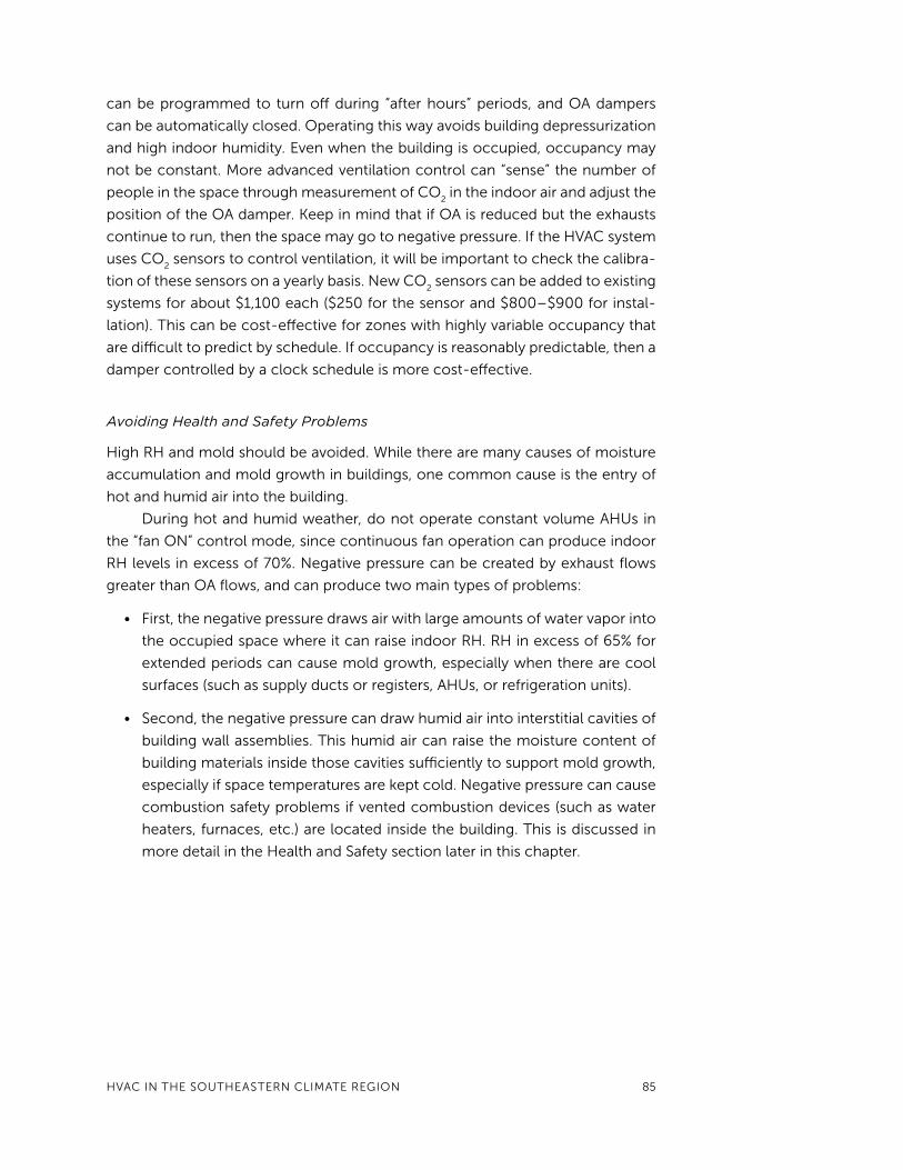
HVAC In tHE SOUtHEAStERn ClIMAtE REGIOn 85
can be programmed to turn off during “after hours” periods, and OA dampers
can be automatically closed. Operating this way avoids building depressurization
and high indoor humidity. Even when the building is occupied, occupancy may
not be constant. More advanced ventilation control can “sense” the number of
people in the space through measurement of CO2 in the indoor air and adjust the
position of the OA damper. Keep in mind that if OA is reduced but the exhausts
continue to run, then the space may go to negative pressure. If the HVAC system
uses CO2 sensors to control ventilation, it will be important to check the calibra-
tion of these sensors on a yearly basis. new CO2 sensors can be added to existing
systems for about $1,100 each ($250 for the sensor and $800–$900 for instal-
lation). this can be cost-effective for zones with highly variable occupancy that
are difficult to predict by schedule. If occupancy is reasonably predictable, then a
damper controlled by a clock schedule is more cost-effective.
Avoiding Health and Safety Problems
High RH and mold should be avoided. While there are many causes of moisture
accumulation and mold growth in buildings, one common cause is the entry of
hot and humid air into the building.
During hot and humid weather, do not operate constant volume AHUs in
the “fan On” control mode, since continuous fan operation can produce indoor
RH levels in excess of 70%. negative pressure can be created by exhaust flows
greater than OA flows, and can produce two main types of problems:
• First, the negative pressure draws air with large amounts of water vapor into
the occupied space where it can raise indoor RH. RH in excess of 65% for
extended periods can cause mold growth, especially when there are cool
surfaces (such as supply ducts or registers, AHUs, or refrigeration units).
• Second, the negative pressure can draw humid air into interstitial cavities of
building wall assemblies. this humid air can raise the moisture content of
building materials inside those cavities sufficiently to support mold growth,
especially if space temperatures are kept cold. negative pressure can cause
combustion safety problems if vented combustion devices (such as water
heaters, furnaces, etc.) are located inside the building. this is discussed in
more detail in the Health and Safety section later in this chapter.
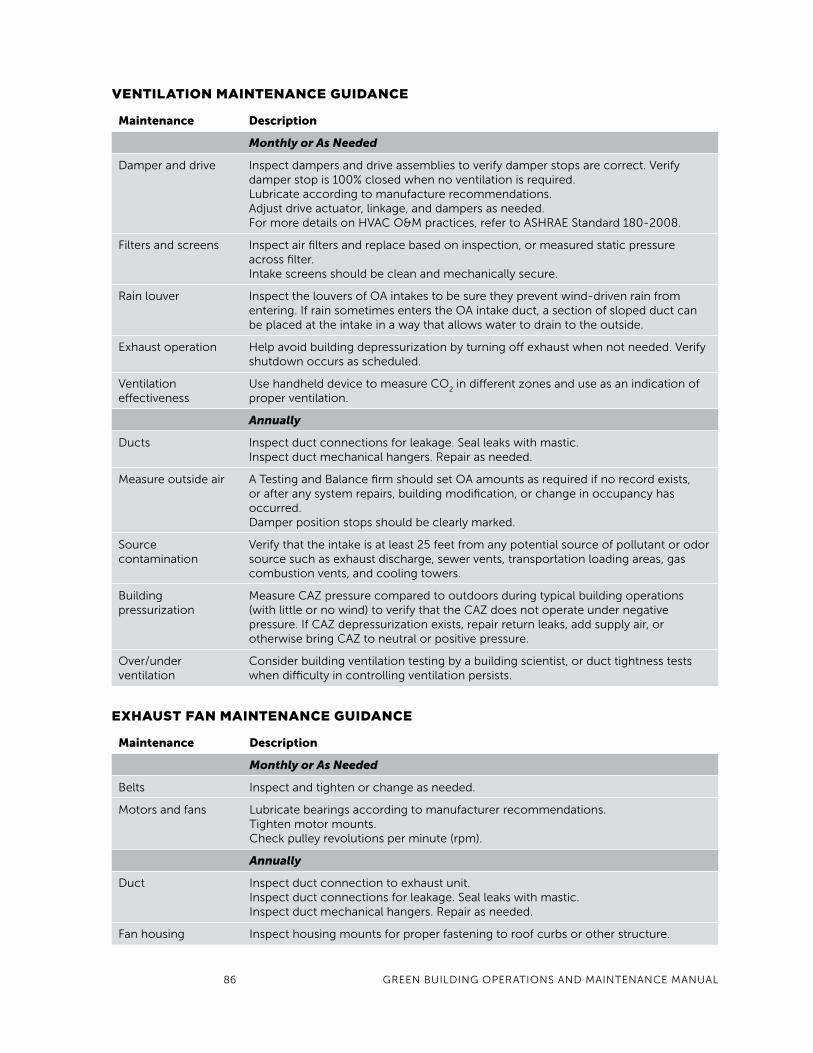
86 GREEn BUIlDInG OPERAtIOnS AnD MAIntEnAnCE MAnUAl
ventILatIon MaIntenance guIdance
Maintenance Description
Monthly or As Needed
Damper and drive Inspect dampers and drive assemblies to verify damper stops are correct. Verify damper stop is 100% closed when no ventilation is required.lubricate according to manufacture recommendations.Adjust drive actuator, linkage, and dampers as needed. For more details on HVAC O&M practices, refer to ASHRAE Standard 180-2008.
Filters and screens Inspect air filters and replace based on inspection, or measured static pressure across filter.Intake screens should be clean and mechanically secure.
Rain louver Inspect the louvers of OA intakes to be sure they prevent wind-driven rain from entering. If rain sometimes enters the OA intake duct, a section of sloped duct can be placed at the intake in a way that allows water to drain to the outside.
Exhaust operation Help avoid building depressurization by turning off exhaust when not needed. Verify shutdown occurs as scheduled.
Ventilation effectiveness
Use handheld device to measure CO2 in different zones and use as an indication of
proper ventilation.
Annually
Ducts Inspect duct connections for leakage. Seal leaks with mastic.Inspect duct mechanical hangers. Repair as needed.
Measure outside air A testing and Balance firm should set OA amounts as required if no record exists, or after any system repairs, building modification, or change in occupancy has occurred. Damper position stops should be clearly marked.
Source contamination
Verify that the intake is at least 25 feet from any potential source of pollutant or odor source such as exhaust discharge, sewer vents, transportation loading areas, gas combustion vents, and cooling towers.
Building pressurization
Measure CAZ pressure compared to outdoors during typical building operations (with little or no wind) to verify that the CAZ does not operate under negative pressure. If CAZ depressurization exists, repair return leaks, add supply air, or otherwise bring CAZ to neutral or positive pressure.
Over/under ventilation
Consider building ventilation testing by a building scientist, or duct tightness tests when difficulty in controlling ventilation persists.
exHaust fan MaIntenance guIdance
Maintenance Description
Monthly or As Needed
Belts Inspect and tighten or change as needed.
Motors and fans lubricate bearings according to manufacturer recommendations.tighten motor mounts.Check pulley revolutions per minute (rpm).
Annually
Duct Inspect duct connection to exhaust unit.Inspect duct connections for leakage. Seal leaks with mastic.Inspect duct mechanical hangers. Repair as needed.
Fan housing Inspect housing mounts for proper fastening to roof curbs or other structure.

HVAC In tHE SOUtHEAStERn ClIMAtE REGIOn 87
comfort controls
Comfort controls are devices such as thermostats, humidistats, and ventilation
controls intended to maintain a desired temperature, humidity, and air qual-
ity. this section discusses sensors and their limitations in controlling comfort,
followed by a brief summary of comfort controls operations and maintenance
practices.
Background and Issues
Air is generally regarded as a simple invisible gas, but it is actually a complex mix-
ture of gases, water vapor, and particles having thermal energy. the condition
of air determines how comfortable and healthy the environment is for people.
HVAC systems can and often do control a variety of indoor environmental fac-
tors including temperature, humidity, levels of air contamination, and ventilation
rates.
Thermostats
thermostats control space temperature. A key characteristic of thermostats is
“dead band,” which is also related to the cycling rate of the heating and cooling
system. Dead band is the temperature range from when the system turns on to
when it turns off. thermostats commonly operate with a dead band of 2–3°F. For
heating systems, this dead band may be an adjustable value, allowing the facil-
ity manager to select a cycling rate appropriate for the type of heating system.
Hydronic radiator heating with water or steam, for example, may require con-
siderably longer cycles, since the mass of the heat distribution system and heat
transfer rate from the boiler to the room air is much longer than for systems that
use air distribution. the thermostat then needs to anticipate that considerable
heat is stored in the piping and radiators, increasing the potential for overheating
the space if the system continues to provide heat to the space without proper
anticipation.
thermostats that control space cooling normally do not have adjustable
dead bands or cycle rates. One major manufacturer designs thermostats to cycle
the AC system three times per hour when operating at 50% of full load (10 min-
utes on, 10 minutes off, 10 minutes on, etc.). Some thermostats cycle the system
more often, with five or more cycles per hour. this short-cycling can cause the
AC system to not dehumidify as effectively, because it takes several minutes for
the cooling coil to become fully cold.
Humidistats
Humidistats are sometimes used to control indoor RH by controlling the equip-
ment that can affect indoor RH. Humidistats can operate dehumidifiers or

88 GREEn BUIlDInG OPERAtIOnS AnD MAIntEnAnCE MAnUAl
ventilation systems. During cold weather, turning on exhaust systems can lower
indoor RH by introducing dry or cold air from outdoors. Humidistats can also be
integrated into the operation of the central AC system to alter various system
operational parameters to improve latent cooling (moisture removal from the
room air). With standard Dx cooling systems, the humidistat may adjust the AHU
fan flow rate to produce colder supply air. With chilled water systems, humidistat
control might be used to reset either the supply air temperature control point or
the chilled water setpoint.
Humidistats have historically had control accuracy problems. lab testing
has found that humidistats often have inaccurate dial settings. Additionally, hu-
midistat dead bands are often very broad, in the range of 10 percentage points or
more. this can mean, for example, that if a humidistat turns on a device at a set-
point at 54% RH, it might not shut off that device until RH drops to 44% or lower.
In many circumstances, this could mean that the device being controlled might
never turn off, since the equipment being controlled cannot achieve humidity
this low in humid climates. It is important, therefore, to examine resulting control
cycling of the device to make sure that the desired control is achieved. to check,
use a trusted source for humidity measurements during active humidistat con-
trol and record the RH when the system turns on and off. Ideally, the dead band
should be no more than 5% RH, but units with this tight of control cost about
$200. Units around $50 tend to have wider dead bands but can be acceptable if
they are calibrated regularly. Humidistats with dead bands greater than 10% RH
should not be used.
Ventilation Control
Ventilation can be controlled based on schedule or occupancy detection. to
save energy and improve control over indoor RH, it is good practice to shut
off exhaust fans and close outdoor air dampers during unoccupied periods.
Occupancy detection can be achieved by occupancy sensors or by carbon diox-
ide detectors, either of which can activate the ventilation systems when it detects
occupants in the building. Carbon dioxide control will save more energy because
the ventilation will not activate until a sufficiently large number of people are in
the building, raising indoor carbon dioxide levels to approximately 1000 parts per
million (ppm).
Comfort Control Operation
Temperature Control
the following measures can help control temperature:
• consIder turnIng off tHe Hvac systeMs after BuILdIng oc-
cuPants Have Left for tHe day. this practice includes adjusting the
temperature setpoints and shutting down the exhaust and OA flows.

HVAC In tHE SOUtHEAStERn ClIMAtE REGIOn 89
• adjust tHe PrograMMIng of tHe tHerMostat or autoMatIon
systeM to initiate system start-up sufficiently early in the morning, so that
the building can return to acceptable comfort conditions by the time the
work day begins.
• exaMIne sources of Heat or coLd tHat MIgHt affect controL,
if temperature control complaints are reported. Re-calibrate thermostats in
these areas.
• avoId LocatIng tHerMostats on exterIor waLLs, where the sun
can shine on the controller, or near heat-generating office equipment.
• consIder usIng Low-cost teMPerature and rH data Loggers
to track indoor conditions at the thermostat and at other locations within
the space over a several-day or longer period. this will allow detection of
temperature variations across the space and through time.
Humidity Control
• Humidistats are not often used in public housing common spaces. If you
do use them, examine HvAC devices that they control from time to time
to confirm that the desired control is being achieved due to the issues
previously raised.
Control of Ventilation and HVAC
• sHut down exHaust fans wHen tHe BuILdIng Is unoccuPIed. Shut
outdoor air dampers, to fully closed or mostly closed, during unoccupied
periods.
• Use a Battery Back-uP for clocks used to control HVAC equipment to
maintain correct time during power outages.

90 GREEn BUIlDInG OPERAtIOnS AnD MAIntEnAnCE MAnUAl
HeaLtH and safety
Health and safety are the highest priority in any operations and maintenance
program. Many aspects of HVAC operations and maintenance affect health
and safety, either directly or indirectly, as discussed throughout this chapter.
this section discusses two important areas of concern: mechanical rooms and
combustion safety.
Mechanical rooms
A mechanical room houses HVAC equipment. Sometimes, non-HVAC items
are also stored in them, which, in some cases, detrimentally affects air quality.
Mechanical equipment in this space can also have unintended impacts on air
quality and safety. this section covers some of the complex interactions that
may affect health and safety, and it concludes with operations and a chart on
maintenance guidance.
Background and Issues
Field research has found that air distribution systems, including ductwork,
plenums, and AHUs, experience large amounts of duct leakage, as discussed
coMfort controLs MaIntenance guIdance
Maintenance Description
Daily
Sensor Verify that space conditions are maintained within reasonable expectations.Investigate wall thermostats for exposure to sources of heat or cold.
Quarterly
Clock schedule control
Check clocks and adjust time as needed.
Space condition trending
Record hourly temperature and relative humidity for a typical week during different seasons to verify conditions are maintained as expected. If building system doesn’t have equipment to do this, small loggers can be purchased for this task (price about $80).
Heating/ cooling system performance
Use loggers placed at a return and one at a supply to evaluate temperature difference across heat exchangers, and the delivered supply air temperature.
Annually
thermostats, occupancy sensors, and CO
2 sensors
Calibrate control sensors according to manufacturer specifications. Replace or calibrate sensors that perform outside the manufacture specifications. Use high accuracy sensors when replacement is needed.
HVAC In tHE SOUtHEAStERn ClIMAtE REGIOn 91
previously. these leaks are often drawn from the mechanical room in which the
AHUs are located.
Air distribution system leakage can create energy waste and indoor air qual-
ity problems through three ways that have implications for mechanical rooms:
• aIr dIstrIButIon systeM Leakage can transPort PoLLutants
froM a contaMInated sPace Into tHe condItIoned sPace. If zones
that contain AHUs or ductwork contain air contaminants, those pollutants
will almost certainly be delivered into the conditioned space. For this rea-
son, mechanical rooms must be kept clean and dry. Standing water can
lead to growth of mold, bacteria, or algae, especially if it comes into contact
with dirt or soft building materials. Do not store chemicals, wet mops, or full
mop buckets in mechanical rooms. these materials should be located in a
janitorial closet with an appropriate sized exhaust fan. Mechanical rooms
below grade may have mold and musty odors, because of contact with cold
soil and elevated levels of radon, each of which can be transported to the
conditioned space.
• aIr dIstrIButIon systeM Leakage can Produce sPace dePres-
surIzatIon tHat can cause tHat sPace to draw contaMInants
Into tHe BuILdIng. Return leaks can produce depressurization of the me-
chanical room, which can draw radon, sewer gases, and combustion gases
into the mechanical room. these will, in turn, be drawn into the air distribu-
tion system and into the conditioned space. If the space pressure becomes
sufficiently negative, sewer gases may be drawn from drain traps, especially
if there is little or no water in the trap.
• aIr dIstrIButIon systeM Leakage can Produce sPace dePres-
surIzatIon tHat can actuaLLy generate aIr quaLIty ProBLeMs.
Return leaks may cause depressurization of the mechanical room or other
spaces in the building. this depressurization can transport high moisture
content air (especially during hot and humid weather) into interstitial cavi-
ties. Moisture build-up in building materials can lead to mold growth, and
spores and mold odors can then be transported into the building. this de-
pressurization can, if the level of depressurization is sufficiently aggressive,
also cause large rates of carbon monoxide generation (see below).
Operations
to prevent health and safety problems related to mechanical room operations:
• keeP MecHanIcaL rooMs cLean: Mechanical rooms that contain
AHUs should be kept clean and dry, because the air in those rooms is also
transported through leakage to the conditioned space.
92 GREEn BUIlDInG OPERAtIOnS AnD MAIntEnAnCE MAnUAl
• Make sure tHat aIr condItIonIng condensate Is caPtured and
draIned: Condensate pumps may be used to remove condensate from
sealed combustion gas furnace and water heaters. Condensate pumps and
lines should be inspected every three months to verify that lines are clean
and clear, and that the pump is in good working order. Inspection of the
pump should verify that it operates when water is present at its collection
point. If the pump is not running at the time of inspection, some water
could be added to the collection point to force the pump to operate. If
pump does not operate, verify that there is electric power supplied to the
pump and replace pump if needed. Inspection of condensate lines and pans
should look for evidence of cracked or blocked lines indicated by drips, or
by water backed up higher in pans or other collection reservoirs. the lines
should be pulled and pressurized air or water forced through them at least
once a year to keep lines cleared of debris.
• cHeck MecHanIcaL rooM Pressure: Using a manometer, measure the
pressure in the mechanical room with reference to the interior spaces of
the building and also with respect to outdoors. If the room is operating at
a negative pressure compared to outdoors, take steps to bring the room to
neutral or positive pressure. Sometimes mechanical rooms are built to be
part of the return air system and are therefore intentionally depressurized. If
depressurization is creating problems, it may be necessary to hard-duct the
return directly to the AHU.
• seaL return sIde aIr Leakage: While sealing all duct leakage is good
practice, it is especially important for mechanical rooms that may have mold
and musty odors, vented combustion appliances, or radon in soil below a
mechanical room.
combustion safety
Background and Issues
Vented combustion devices, such as gas water heaters, gas or oil furnaces, and
gas or oil boilers, produce combustion byproducts such as carbon dioxide, car-
bon monoxide, water vapor, nitrogen oxides, small diameter particulates, and
other products. In large part, these effluents are dangerous to human beings.
therefore, it is important that they are vented to outdoors. In many cases, proper
venting depends upon the buoyancy of the hot gases to move them upward
through a vent and successfully deliver them to outdoors. this buoyancy is a
relatively weak force and can be easily overcome by negative pressure in the
combustion appliance zone (CAZ). Four stages of space depressurization impact
should be considered and avoided (Figure 5):
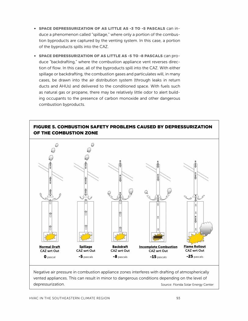
HVAC In tHE SOUtHEAStERn ClIMAtE REGIOn 93
• sPace dePressurIzatIon of as LIttLe as -3 to -5 PascaLs can in-
duce a phenomenon called “spillage,” where only a portion of the combus-
tion byproducts are captured by the venting system. In this case, a portion
of the byproducts spills into the CAZ.
• sPace dePressurIzatIon of as LIttLe as -5 to -8 PascaLs can pro-
duce “backdrafting,” where the combustion appliance vent reverses direc-
tion of flow. In this case, all of the byproducts spill into the CAZ. With either
spillage or backdrafting, the combustion gases and particulates will, in many
cases, be drawn into the air distribution system (through leaks in return
ducts and AHUs) and delivered to the conditioned space. With fuels such
as natural gas or propane, there may be relatively little odor to alert build-
ing occupants to the presence of carbon monoxide and other dangerous
combustion byproducts.
fIgure 5. coMBustIon safety ProBLeMs caused By dePressurIzatIon of tHe coMBustIon zone
negative air pressure in combustion appliance zones interferes with drafting of atmospherically
vented appliances. this can result in minor to dangerous conditions depending on the level of
depressurization. Source: Florida Solar Energy Center
normal DraftCAZ wrt Out
0 pascal
SpillageCAZ wrt Out
-5 pascals
backdraftCAZ wrt Out
-8 pascals
incomplete CombustionCAZ wrt Out
-15 pascals
flame RolloutCAZ wrt Out
-25 pascals

94 GREEn BUIlDInG OPERAtIOnS AnD MAIntEnAnCE MAnUAl
• sPace dePressurIzatIon In tHe range of -15 to -20 PascaLs can
create a particularly dangerous circumstance of “incomplete combustion.”
the relatively strong negative pressure in the CAZ causes air to flow down-
ward through the vent at a high velocity. this airflow discharges from the
vent onto the top of the water heater or other combustion device, imping-
ing upon the discharge of the appliance flue (which is the vent inside the
combustion appliance). the flue continues to vent upward into the room,
but with reduced airflow. this reduced rate of airflow in turn slows the entry
of combustion air into the combustion chamber of the water heater. With
insufficient combustion air, the appliance that might otherwise produce lit-
tle carbon monoxide (say, in the range of 10 ppm) might suddenly produce
very large amounts of carbon monoxide (perhaps in the range of 50,000
ppm). these high levels of carbon monoxide can lead to carbon monoxide
poisoning and even death to building occupants.
• sPace dePressurIzatIon In tHe range of -20 to -25 PascaLs and
greater can produce flame rollout. In this circumstance, the air velocity
downward through the vent impinges on the appliance flue with sufficient
force to reverse the direction of airflow in the flue itself. When the appliance
cycles on, the gas ignites but the flame does not remain inside the combus-
tion chamber. Rather, the flame is pushed out of the combustion chamber
by the air moving down the flue. Some portion of the flame then burns out-
side the appliance, creating the likelihood that materials around the water
heater will ignite.
Some combustion appliances have venting systems that resist the effects
of space depressurization. Sealed combustion appliances are not atmospheri-
cally vented. Combustion air is delivered into the appliance from outdoors, which
is not affected by the pressure field in the CAZ. Power draft equipment is also
largely unaffected by space pressure. A fan is used to push the combustion gases
from the building. In most cases, the fan has sufficient power to overcome the
effect of CAZ depressurization.
As indicated in the Air Distribution System section of this chapter, duct leaks
(especially return leaks) in mechanical rooms must be sealed to avoid depres-
surization. However, even when they are sealed, space depressurization is still
possible.
For example, simply removing the filter access panel can produce substan-
tial levels of space depressurization. If a maintenance person fails to replace that
panel, a dangerous level of negative pressure could persist in the CAZ. It is also
important that exhaust fans do not operate in mechanical rooms, unless it is veri-
fied that their operation does not significantly affect pressure in that space.
Combustion appliances typically require combustion and dilution air from
the space. the national Fuel Gas Code, known as standard nFPA 54, defines
requirements for venting to provide the necessary levels of combustion and

HVAC In tHE SOUtHEAStERn ClIMAtE REGIOn 95
dilution air. the vents must remain unobstructed in order to allow the necessary
air into the CAZ. therefore, equipment, boxes, and other items should never be
placed in front of the combustion and dilution air vent openings.
MecHanIcaL rooM and coMBustIon safety MaIntenance guIdance
Maintenance Description
Daily
Storage in mechanical room
Implement a policy of limited storage. Inspect and remove stored cleaning materials or other chemicals.Avoid storing combustible materials nearby any combustion appliance.
Mechanical room– clean and dry
Clean the mechanical room before dirt/dust levels build up. Remove wet materials immediately and determine cause and solution for wetness.
Carbon monoxide (CO)
Make sure CO detectors are located in CAZ and are functional.Designate responsibility to staff to be aware of alarms.
Quarterly or After Any Service Work Done in Mechanical Room
Combustion/dilution air
Verify that combustion/dilution vents’ size and installation comply with the construction building documents or with the national Fuel Gas Code (standard nFPA54) for all gas appliances located in the CAZ.
Avoidance of room depressurization
Measure mechanical room and CAZ pressure with reference to outside and take action to neutralize depressurization beyond -3 pascals.Inspect AHU panels for leakage. Seal leaks with Ul approved tapes and putty.Seal return duct leaks in CAZ or mechanical rooms with mastic.If CAZ is still depressurized, add some supply air into the CAZ or replace natural draft appliances with sealed or forced-draft combustion appliances.Measure CO levels in CAZs or test CO monitor in room.
Wall moisture Spaces below grade should have wall inspections to look for signs of moisture or mold. Damp external walls signify serious moisture control problems requiring immediately professional assessment.
Annually
Radon Conduct a radon test. Consult EPA guidelines on required action and frequency of follow-up testing based on initial test results. Generally seal all ground floor and below-grade penetrations. note that some plumbing and electric penetrations are located inside wall cavities.
Review list of combustion appliances
Place all natural-drafted combustion appliances on list of equipment for high-priority replacement. Replace with sealed combustion or power-draft equipment. Energy Star gas appliances generally use sealed combustion venting, and yield reduced energy consumption and improved air quality control.
Carbon monoxide Consider measuring CO in the combustion flue. Have appliances serviced by qualified person if vented CO concentration exceeds 50 ppm or if CO detector alarm is tripped. Replace CO detector batteries annually or at manufacturer’s suggested schedule.Review with all staff or new hires, proper procedure for investigating alarms, alerting emergency professionals when needed, and evacuation.

96 GREEn BUIlDInG OPERAtIOnS AnD MAIntEnAnCE MAnUAl
LIMItIng Loads froM devIces BrougHt In By eMPLoyees
Employees may bring electrical devices with a wide range of power usage into
the facility. these devices may include desk lamps, table fans, and space heaters.
Without a plan or policy in place, these devices can hamper energy conservation
efforts and possibly create environmental hazards.
Impact of devices
Some devices brought in by employees use relatively little energy, while oth-
ers consume considerable energy and may also represent a fire hazard. Building
operations and maintenance personnel often ignore such devices unless they
interfere with the proper operation of the system. In general, these devices have
the potential to significantly increase the building’s energy consumption. limiting
use of unnecessary electric devices will not only conserve energy used by the
device itself, but also reduce the space conditioning load.
employee Personal device guidance
to deal with these devices:
• conduct a BuILdIng survey to IdentIfy HeatIng or cooLIng de-
vIces BrougHt In By BuILdIng occuPants, which may indicate they
have additional heating or cooling needs.
• recognIze no sIngLe set of Indoor condItIons Is coMfortaBLe
for everyone. People have different metabolic rates and levels of cloth-
ing. Additionally, space conditions often vary from one location to another
within a building or zone. thus, some requests for supplemental space con-
ditioning devices are valid.
• In tHe case of suPPLeMentaL sPace condItIonIng devIces (e.g.,
sPace Heaters), IdentIfy tHe cause of tHe coMPLaInt tHat
Leads to BrIngIng tHe devIce to work. If the space is too cold dur-
ing the summer, try to adjust the space temperature at that workstation to
accommodate the employee’s or occupant’s comfort needs. If the space
is too cold during the winter, see if supply airflow can be increased to that
work area. Alternatively, try to modify cold envelope features (e.g., nearby
windows, poorly insulated walls, or drafts) to improve localized comfort.
• set guIdeLInes for suPPLeMentaL devIces (maximum wattages,
safety ratings, etc).

HVAC In tHE SOUtHEAStERn ClIMAtE REGIOn 97
table 2 provides examples of such devices and the relative amount of pow-
er each consumes. Keep in mind that some devices consume energy even when
turned off or not in use. One clue that a device may be using energy even after it
is turned off is to feel for warmth at the power supply or on the device. Examples
of policies to consider are in the far-right column, although it is generally more
effective to obtain input from and buy-in by staff occupying the space before
setting new policies.
taBLe 2. exaMPLes of PersonaL devIces and usage PoLIcIes
equipmentRelative power (Approx. wattage) example Policy
Battery chargers (small electronics)
low (15W–30W)
Unplug when not used.
Radio low(40W)
Unplug when not used.
Desk lamp low–medium(40W–100W)
turn off when not used. limit lamp to appropriate wattage and use high efficiency bulbs when practical.
Personal size floor fan low–medium(20W–60W)
turn off when leaving space. Consider controlling by occupancy sensor.limit fan size to that appropriate for space. (Example: 6”-8” diameter fan for single workspace at desk).
Oscillating circulation fan Medium–high(30W–60W)
turn off when leaving space. limit to task areas more open that require movement within space or more than one person in area.
Personal space heater High–very high(150W– >500W)
Discourage use, but allow in cases where existing heating is inadequate for personal needs. Permit only heaters with tip over safety shut-off. Have users sign a “safe- use” policy agreement that also establishes a max. watt limit appropriate for each space. (Example: small workspace limited to 300 watts). ALWAyS turn off when leaving space.
Small cooking appliancesmicrowave, hot plates, toaster oven
Very high(>500W)
limit to single appliances that can be shared.
Small personal space cooling(self-contained units or window AC)
Very high(>500W)
low probability employee will bring in personal AC. If installed, make sure condensate can be properly drained without leaking or spilling. Waste heat must be properly vented to outdoors.turn off when leaving space.
Small refrigerators Medium(150W but cycles)
Encourage group sharing of one larger refrigerator, which consumes much less energy than several small units.
98 GREEn BUIlDInG OPERAtIOnS AnD MAIntEnAnCE MAnUAl
equIPMent rePLaceMent or uPgrades
Many public housing buildings were built more than 30 years ago when energy
was still considered inexpensive. there is, therefore, great potential for energy
conservation by upgrading to more efficient choices when replacing cooling and
heating equipment or when considering alternative energy systems.
replacing cooling equipment
Cooling equipment will be replaced for many reasons from time to time. Some
equipment will have reached the end of its useful life. Replacement could also
be prompted by the need for improved system reliability. When replacing equip-
ment, energy efficiency should be a major consideration, not only because of the
environment, but also because it may be the most cost-effective choice.
In the past few decades, the energy efficiency of AC systems has increased
dramatically. Units purchased prior to 1991 typically had SEER ratings in the range
of 6 to 8. During the 1990s, AC system efficiency gradually increased. A major
step forward occurred in 2006, when the minimum SEER rating that could be
manufactured was raised from 10 to 13. the availability and cost of very high ef-
ficiency split Dx equipment, in the 15–17 SEER range, has improved substantially
with rebates available through manufacturers, utilities, and federal programs. the
efficiency of chillers has also improved substantially. Variable-speed, variable-
capacity chillers that can provide super high efficiency under part load are now
on the market. Some chiller units have efficiency ratings as low as 320 Watts
per ton at 50% or lower load factor, which is as much as 50% lower energy use
compared to standard new chillers.
Energy efficiency heavily influences the lifecycle cost of cooling systems.
Consider the first cost and total energy cost of two AC systems (see Box 2). the
cost of a replacement five-ton SEER 13 AC system might be $6,000, compared
to $9,500 for a SEER 21 unit. In some cases, utility or government incentives may
narrow the price differential. If the unit operates for 2,000 hours per year and the
Box 2. How to estIMate savIngs Between seer 13 and seer 21 60,000 BtuH (5 ton) systeMs
SEER 13: 60,000 Btuh/13 Btu/w = 4.615 kWh/hr x 800 hours x $0.11/kWh = $406 per year
SEER 21: 60,000/21 = 2.857 kWh/hr x 800 hours x $0.11/kWh = $252 per year
Difference = $154 per year

HVAC In tHE SOUtHEAStERn ClIMAtE REGIOn 99
cost of electricity is $0.11 per kWh, it will take 9 years for the energy savings from
the SEER 21 unit to pay for the added cost.
Installing Higher efficiency aHus, fan Motors,
and variable speed drives
Energy efficiency improvements can also be achieved by means of higher effi-
ciency fans and fan speed controllers. In the past decade, variable-speed AHUs
(using electronically commutated fan motors) have become widely available.
By themselves, these higher efficiency fan motors can increase SEER rating by
1 point, e.g., from SEER 13 to SEER 14. When installed with properly sized (or
oversized) duct systems, they can achieve substantial energy savings in and of
themselves compared to conventional shaded-pole motors.
AHU fans in larger commercial-sized systems can also be modified to op-
erate much more efficiently using variable frequency drives (VFDs). VFDs adjust
fans to a lower fixed airflow rate. they can also be used to vary AHU airflows in
real time in response to temperature offset from thermostat setpoints or in re-
sponse to VAV box damper settings. Benefits include 1) reduced fan power, 2) less
potential for overcooling of the space and concomitant need for reheat, and 3)
extended life of the air-moving equipment and filters.
Exhaust fans can also benefit from VFDs. If exhaust airflow rates are found
to be larger than required, then an installed VFD can lower the exhaust fan air-
flow rate. this can reduce exhaust fan energy use and shrink ventilation-related
heating and cooling loads.
replacing Heating equipment
Whether replacing electric or gas heating systems, PHA buildings can become
more energy efficient.
Electric Heating Systems
Electric resistance heating, common in PHAs, is very energy inefficient. Many
higher efficiency heating equipment options are available. When selecting elec-
tric heating systems, consider heat pumps, which are about 3 times more effi-
cient than electric “strip” heat.
Heat pump efficiency can be compared by heating seasonal performance
factor (HSPF) or coefficient of performance (COP). Higher numbers indicate
higher efficiency. Heat pumps are very suitable for cooling-dominated climates,
although the need remains to have properly sized back-up strip heat for the
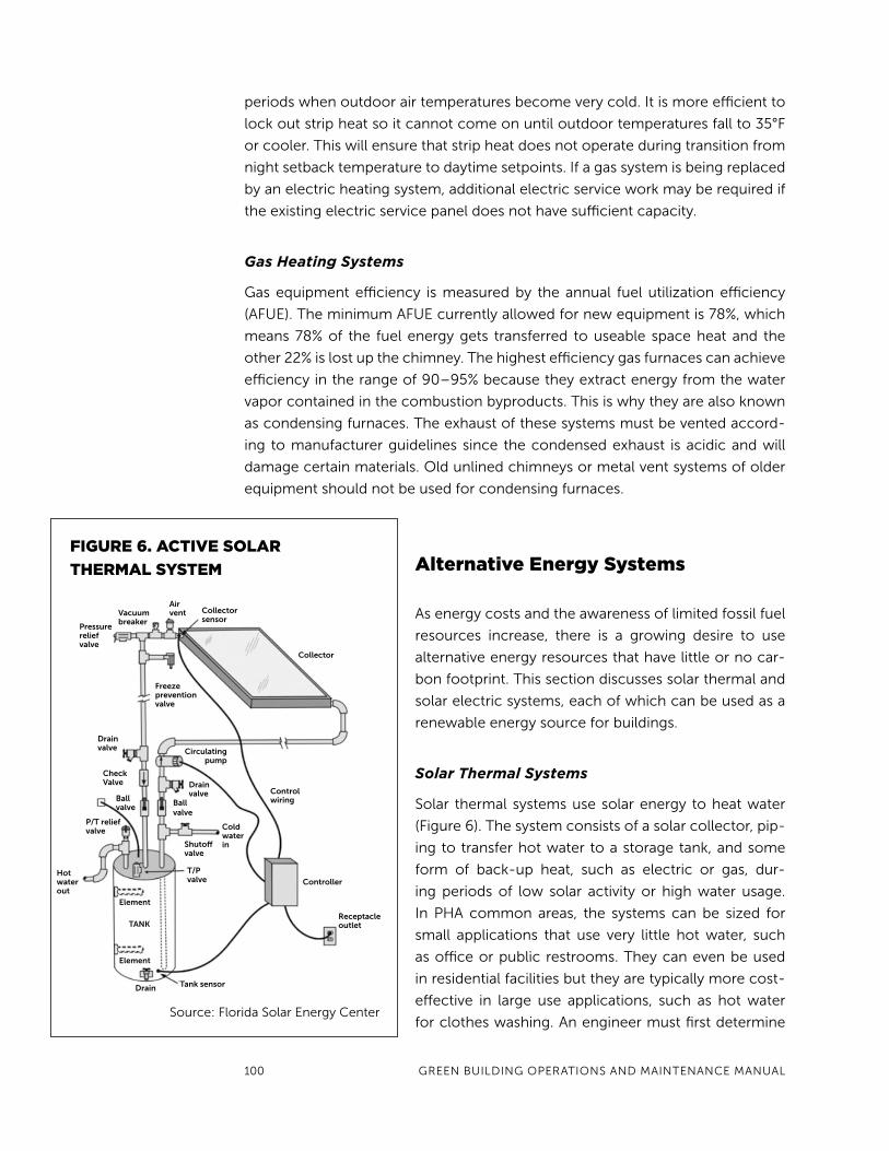
100 GREEn BUIlDInG OPERAtIOnS AnD MAIntEnAnCE MAnUAl
periods when outdoor air temperatures become very cold. It is more efficient to
lock out strip heat so it cannot come on until outdoor temperatures fall to 35°F
or cooler. this will ensure that strip heat does not operate during transition from
night setback temperature to daytime setpoints. If a gas system is being replaced
by an electric heating system, additional electric service work may be required if
the existing electric service panel does not have sufficient capacity.
Gas Heating Systems
Gas equipment efficiency is measured by the annual fuel utilization efficiency
(AFUE). the minimum AFUE currently allowed for new equipment is 78%, which
means 78% of the fuel energy gets transferred to useable space heat and the
other 22% is lost up the chimney. the highest efficiency gas furnaces can achieve
efficiency in the range of 90–95% because they extract energy from the water
vapor contained in the combustion byproducts. this is why they are also known
as condensing furnaces. the exhaust of these systems must be vented accord-
ing to manufacturer guidelines since the condensed exhaust is acidic and will
damage certain materials. Old unlined chimneys or metal vent systems of older
equipment should not be used for condensing furnaces.
alternative energy systems
As energy costs and the awareness of limited fossil fuel
resources increase, there is a growing desire to use
alternative energy resources that have little or no car-
bon footprint. this section discusses solar thermal and
solar electric systems, each of which can be used as a
renewable energy source for buildings.
Solar Thermal Systems
Solar thermal systems use solar energy to heat water
(Figure 6). the system consists of a solar collector, pip-
ing to transfer hot water to a storage tank, and some
form of back-up heat, such as electric or gas, dur-
ing periods of low solar activity or high water usage.
In PHA common areas, the systems can be sized for
small applications that use very little hot water, such
as office or public restrooms. they can even be used
in residential facilities but they are typically more cost-
effective in large use applications, such as hot water
for clothes washing. An engineer must first determine
fIgure 6. actIve soLar
tHerMaL systeM
Source: Florida Solar Energy Center
Collector
Collector sensor
Air ventvacuum
breakerPressure relief valve
Freeze prevention valve
Drain valve
Check valve
Ball valve
P/T relief valve
Hot water out
Element
TAnK
Element
Drain Tank sensor
Circulating pump
Drain valve
Cold water in
Ball valve
Shutoff valve
T/P valve
Control wiring
Controller
Receptacle outlet

HVAC In tHE SOUtHEAStERn ClIMAtE REGIOn 101
site suitability, which includes available space for collectors, orientation to the
sun, potential for shading of collectors, and available space for hot water tanks.
Solar thermal systems generally require little attention. Maintenance will involve
confirming that the circulation pumps are working (through weekly inspection),
repairing plumbing leaks that may occur, and cleaning collector surfaces during
extended periods without rain.
Solar Electric Systems
Solar electricity is produced by photovoltaic (PV) panels commonly installed on
a roof. In typical systems, the direct current produced by
the panels is converted to alternating current using an
inverter and then injected into the utility grid. If the PV
system is producing more energy than the building is con-
suming, then the electric meter in effect runs backward.
Just as in solar thermal systems, an engineer must
evaluate the useable area of the roof and consider limit-
ing factors such as shading and weight load imposed on
the roof by solar collectors. Solar electric performance is
drastically affected by shading, since shade over just 10%
of the panel surface area can result in 90% reduction of
power output in some configurations. PV systems cost
around $7–8 per installed Watt of capacity, and prices are
expected to drop substantially in the coming years. State
and federal sources may offer incentives to reduce system
cost. While the life of the solar panels may be 20 years
or longer, the inverter is likely to have a life of only 5–15
years. A replacement 4000W inverter may cost $2,000 to
$3,000. Solar electric systems require little maintenance.
the collector surfaces may need to be cleaned during
extended periods without rain.
When comparing solar versus building efficiency,
the best return on investment is improved building effi-
ciency. the priority should be to optimize the energy ef-
ficiency of the building envelope and HVAC systems, and
then consider implementing renewable energy produc-
tion. On the other hand, societal and environmental costs
and consequences related to fossil fuel extraction and
consumption are often not accounted for in building site
financial analysis.
Crystalline modules mounted on a sloped roof. Source: Florida Solar Energy Center
Thin film modules mounted on a flat roof. This flat-roof type is generally less efficient and requires more roof area than a sloped system. Source: Florida Solar Energy Center
102 GREEn BUIlDInG OPERAtIOnS AnD MAIntEnAnCE MAnUAl
acronyMs In tHIs cHaPter
AC Air conditioning
ADS Air distribution system
AFUE Annual fuel utilization efficiency
AHU Air handler unit
ASHRAE American Society of Heating, Refrigerating and
Air-Conditioning Engineers
BTU British thermal unit
BTUH British thermal unit per hour
CAZ Combustion appliance zone
CDD Cooling degree days
Cfm Cubic feet per minute
DDC Direct Digital Control
DHW Domestic hot water
DOE Department of Energy
DX Direct expansion
EPA Environmental Protection Agency
FEMP Federal Energy Management Program
HDD Heating degree day
HVAC Heating, ventilation, and air conditioning
kWh kilowatt hour
MERV Minimum Efficiency Report Value
NAIMA North American Insulation Manufacturers Association
NGFA National Fuel Gas Code
OA Outdoor air
PHA Public Housing Authority
Ppm Parts per million
Psig pounds per square inch gauge
PTAC Package terminal air conditioner
PV Photovoltaic
RH Relative humidity
RTU Rooftop package unit
SEER Seasonal energy efficiency ratio
SMACNA Sheet Metal and Air Conditioning Contractors
National Association
VAV Variable air volume
VFD Variable frequency drive