Chapter 16 ANCIENT MODULATION And other topics - QRP ARCI
21
1. Chapter 16, Harris CRYSTAL SETS TO SIDEBAND © Frank W. Harris 2010, REV 12 Chapter 16 ANCIENT MODULATION And other topics When I got back into ham radio 11 years ago, my ham friends told me that amplitude modulation (AM) was extinct. I was under the impression that SSB was the only mode of HF phone permitted. Later I learned that AM isn't actually illegal and there are a few diehards using AM on the 75 and 10 meter phone bands. I've also heard AM stations on 15 and 160 meters. In short, you might find a use for it. Besides, it's an interesting challenge to AM-modulate a transistorized transmitter. Homebuilt AM Back in the vacuum tube days many of us built our own transmitters and AM modulators. My first AM transmitter was a Heathkit DX-20. That was a 50 watt, CW-only, kit-built, vacuum tube transmitter to which I added a homebuilt AM modulator. Unlike SSB, AM could be added onto an existing CW transmitter. Rather than generate a low power AM signal and then amplify it with a linear amplifier, in the old days the usual method was to AM-modulate the final amplifier of the CW transmitter. On an oscilloscope, the hallmark of AM is that, when you are not speaking, the RF carrier wave runs continuously at an average power. That is, in AM the highest peak power and zero power only occur at the very highest voice peaks. Although I could see these transient peaks
Transcript of Chapter 16 ANCIENT MODULATION And other topics - QRP ARCI

1. Chapter 16, Harris
CRYSTAL SETS TO SIDEBAND © Frank W. Harris 2010, REV 12
Chapter 16
ANCIENT MODULATION
And other topics
When I got back into ham radio 11 years ago, my ham friends told me that amplitude modulation (AM) was extinct. I was under the impression that SSB was the only mode of HF phone permitted. Later I learned that AM isn't actually illegal and there are a few diehards using AM on the 75 and 10 meter phone bands. I've also heard AM stations on 15 and 160 meters. In short, you might find a use for it. Besides, it's an interesting challenge to AM-modulate a transistorized transmitter.
Homebuilt AM
Back in the vacuum tube days many of us built our own transmitters and AM modulators. My first AM transmitter was a Heathkit DX-20. That was a 50 watt, CW-only, kit-built, vacuum tube transmitter to which I added a homebuilt AM modulator. Unlike SSB, AM could be added onto an existing CW transmitter. Rather than generate a low power AM signal and then amplify it with a linear amplifier, in the old days the usual method was to AM-modulate the final amplifier of the CW transmitter.
On an oscilloscope, the hallmark of AM is that, when you are not speaking, the RF carrier wave runs continuously at an average power. That is, in AM the highest peak power and zero power only occur at the very highest voice peaks. Although I could see these transient peaks

2. Chapter 16, Harris
on the scope, when I tried to catch one with a storage scope, they are statistically rare and I couldn't catch a zero power level. The waveform below was typical of what I saw.
In contrast to AM, the RF output amplitude in SSB is always zero whenever you aren't talking. Notice in the SSB oscilloscope picture below that each RF blip representing the audio starts from zero. It doesn't start from a halfway, continuous carrier level.
Plate, screen, and cathode modulators
Formerly, there were three common methods of AM modulation. The "Mercedes" method was to use a plate modulator transformer. These large iron transformers impressed the audio signal onto the DC supply current. That is, as you talked, the DC input current rose and fell above and below the level of what it would be for a CW sinewave. For a 100 watt transmitter, this transformer was about the size of a softball, weighed a ton, and cost like crazy. The transformer was driven with a big audio amplifier that put out at least 50% of the CW carrier power. In other words, the plate modulator circuitry was nearly as large and expensive as the rest of the transmitter.

3. Chapter 16, Harris
The "Toyota" and "Bicycle" approaches to AM modulation were to modulate the gain of the final amplifier tube by impressing the audio on the screen or cathode, respectively. Screen modulators usually sounded pretty good. Cathode modulation, sometimes called Heizing modulation, tended to produce "down modulation" which meant that power decreased whenever you talked. It sounded just fine, but was inefficient use of RF power output. These methods required less audio power than plate modulation and were easy for a high school kid like me to afford and build.
Modern AM construction
Now forward to 2003. Most modern SSB transceivers have the capability to generate AM modulation. To get into this mode, you read your manual for 20 minutes, bring up menu #26, push button numbers 14, 7, and 12 and you're done. That wasn't hard, I guess. But did you learn anything?
Let's suppose that you're a homebrew fanatic and wish to scratchbuild your own AM rig using transistors. Is that hard? Hmmmmm. Well, for one thing, transistors don't have cathodes and screen grids. Emitters are analogous to cathodes but, as explained above, cathode modulation wasn't all that great. Another difference between tubes and transistors is that, for the same power levels, the final amplifier transistor has DC currents about 50 times larger. So for DC supply modulation, you must impress 5 or 10 ampere audio signals onto the 12 volt DC power supply line. The modulation transformer will have to be just as large, but it will need a super low impedance output winding.
Modulating a transistorized 50-watt CW transmitter
I have a 25-watt, plate modulator transformer from the 1960s designed for use with a

4. Chapter 16, Harris
transistorized audio amplifier modulating a vacuum tube transmitter. In other words, it was designed to modulate a vacuum tube final amplifier, but the modulator itself was transistorized. In those days high power, high frequency transistors didn't exist, so transmitters were built with tubes, but audio circuits could be built with transistors. Since my transformer had low impedance primary windings, I thought I could "run it backward" and supply enough audio current drive to build an AM "collector modulator." I happen to have an old 10-watt vacuum tube hi-fi amplifier, so I used that to drive the high impedance winding on my modulation transformer. Sure enough, even with music my AM modulation sounded great when I broadcast into a dummy load. However, it only modulated about 30% of the carrier amplitude. That is, I was wasting most of my RF power. I could have built a 25-watt vacuum tube output audio amplifier, but I had a more modern idea. Why not use my MOSFET CW keyer as an audio modulator?
The above keyer was originally designed to turn the DC power to my final on and off with a telegraph key. My AM modulation scheme was to turn the MOSFETs half-on with a simple DC potentiometer, then modulate the gates with a 12 volt P-P audio signal. Because I was driving MOSFETs with a low (audio) frequency signal, hardly any power was needed. This simple scheme worked pretty well, but it was extremely finicky to adjust. It was easy to have too much bias or too little and too much modulation or too little. The difficulty was that the gate voltage versus drain current transfer characteristic is rather non-linear. With feedback and a more sophisticated drive circuit, I believe this method can be made to work well.
The SSB approach to AM
At this point in my R&D, I had not yet succeeded in building a practical SSB transmitter. So rather than invest more time on "obsolete modulation," I went back to work on SSB. I figured that, if I ever got the SSB working, it would be easy to downgrade my SSB generator to AM. This turned out to be true. I tried out several variations. The method that was simplest and

5. Chapter 16, Harris
worked the best was bypassing the SSB crystal filter with a switch and unbalancing the
balanced modulator circuit using a circuit that resembles the CW switch.
AM resembles CW in that a sinewave carrier is generated continuously. However, the same "unbalance" switch used as a SSB/ CW mode switch can't be used for AM. When modulation is applied, the instantaneous power must rise above and below the no-speech carrier level. Ideal AM modulation drives the carrier alternately between zero and 200% of the carrier level. Because there is a limit on the signal amplitude available, the carrier must be set to 50%
of the level used for CW. This provides a modulation amplitude range of +/- 100%. A separate AM mode, double-pole switch bypasses the SSB filter and unbalances the modulator 50%. The AM switch is in series with an adjustable 5K ohm resistor that unbalances the modulator just enough to produce the 50% carrier.
The audio gain pot and your voice level should be adjusted to produce voice peaks twice the carrier level. Compared to SSB, you'll find that AM modulation is quite HI-FI. While testing the generator and transmitter on an 80 meter dummy load, music retransmitted from a Walkman was quite acceptable. In contrast, when using SSB, speech sounds OK, but music is really terrible. The principle difference is that the sideband filter greatly attenuates frequencies below 300 Hz whereas AM preserves the low frequencies. Speech transmitted on SSB can sound like the person's normal voice, but music on SSB is really bad. It's just as well. The last I heard, ham music is still illegal.
COMPRESSION BY ACCIDENT Or, sometimes we get lucky
A modern single sideband generator processes the amplified audio from the microphone

6. Chapter 16, Harris
before the audio is fed into the balanced modulator. This "compression" process attempts to equalize the voice peaks so that as many voice elements as possible are transmitted with full Peak-Envelope-Power. Without this process, most of what you have to say will be transmitted with far less than the nominal peak power. When most of your sentences are reduced to QRP muttering, your intelligibility suffers.
In other words, without compression, the single sideband RF envelope of a spoken word is close to zero most of the time. It would look something like the waveform shown above. A compressor circuit attempts to leave the peaks alone while proportionally amplifying the subtle, low voltage waveform wiggles near the horizontal axis. I guess the latest transceivers use digital processing to accomplish this feat. However, 15 years ago a compressor circuit usually performed the following tasks:
1. It amplified the whole audio waveform.
2. It clipped off the highest audio peaks.
3. And finally, it filtered the clipped audio with a 300 Hz to 3KHz bandpass filter.
After compression, the same RF sideband waveform might look something like the above picture. The idea is that all the tiny stuff near zero has been expanded. (These waveforms aren't actual before-and-after pix, but they illustrate the principle.) After transmission some modern

7. Chapter 16, Harris
receivers "re-expand" the waveform to try to restore the original waveform. This entire process is called companding. However, for me, building a homebrew SSB that worked at all seemed plenty difficult. Consequently I didn't worry about secondary issues like "companding."
A crystal filter does more than clip the unwanted sideband
In the beginning I was afraid my RF signal might be too wide. So, because it was relatively easy, I built a 3 KHz audio low pass filter. It turned out that I didn't need it. Once I had passed the 9.000 MHz RF double sideband signal through the crystal filter to cleave off the unwanted sideband, I found that the filter had also removed virtually everything above 3 KHz anyway. Also, when I adjusted the original sinewave frequency to get rid of every trace of the carrier, I found the filter had also clipped off the lower 300 Hz of the audio. It's remarkable how normal a voice can sound without the lower 300 Hz. Voices are quite lifelike. In any case the crystal filter accomplished the same frequency filtering that the ARRL Handbook specified for the audio compressor. Interesting!
An SSB transmitter has several linear amps in series
After the SSB RF signal has been generated at a milliwatt level, the signal must be amplified and converted to the desired hamband. Including the mixer, this meant that my SSB signal had to pass through 5 stages of amplification to get to 100 watts peak. Each linear stage is forward biased so that even tiny signals will be amplified. Without this bias, all you hear are the voice peaks. In other words, an unbiased amplifier cuts off all the little audio signals a compressor tries to accentuate. I knew that the linearity of all these stages in series couldn't possibly be "perfectly linear." But since voices sounded good, I stopped worrying about linearity.
Where has all the AM modulation gone?
I didn't realize that my RF amplifiers were significantly non-linear until I added an Amplitude Modulator mode to my SSB generator. I listened to my little 9 MHz AM generator in my all band shortwave receiver. It sounded great and looked like 100% modulation on the scope. Next I fed the signal from the 9 MHz AM generator into my 80 meter "linear" QRP module which put out about 3 watts on 80 meters. Yes, it worked, but the signal was nearly all carrier. Instead of 100% modulation, on 80 meters I only had about 5% modulation. Where did that huge carrier signal come from? What happened to my modulation?
Transistors aren't linear

8. Chapter 16, Harris
"Linear" implies that big signals will be amplified just as much as the small ones. However, if the raw output of the transistor covers most of the collector operating range, then it happens that small signals are amplified more than big ones. I have two 2N3904 transistors in my chain of amplifiers, so the Base/ Collector current characteristics for this transistor are shown above. Notice that one milliampere of collector current requires 0.017 milliamperes base current. But to get 10 milliamperes of collector current takes 0.085 milliamperes. That's 5 times more base current to get 10 times more collector current. But if you want 100 milliamperes of collector current, you need 3.0 milliamperes of base current. That's an additional 35 times more base current. Sure looks non-linear to me. BEHOLD, A NON-LINEAR COMPRESSOR!

9. Chapter 16, Harris
The "linear" amplifier above illustrates an accidental compressor circuit. The 33K resistor biases the transistor ON so that even tiny RF signals will be amplified. (By the way, the 10K resistor across the inductor keeps the amplifier from oscillating when there is no input signal.) The main reason for the 120 ohm resistor is to provide negative DC feedback to make the amplifier thermally stable. Without the emitter resistor, the amplifier works, but the transistor runs extremely hot. The emitter resistor also makes the amplifier more linear than the transistor characteristic would suggest because the feedback restricts the transistor to a narrower range of operation. However, 120 ohms feedback makes it a long way from linear. 470 ohms is much better, but still far from perfect.
Oh, well, why fight it? To fix my AM mode, I reduced the imbalance of the balanced modulator to just a few percent of voice peaks. This gives me roughly 50% carrier by the time it arrives at the final amplifier. And as for the SSB, it already works well. Apparently I had a pretty darn good compression system all along and I didn't even know it. Imagine! A happy accident! They sure don't happen often.
********************************************************************************
HAM TELEVISION - The Old Way
First, a glimpse of modern amateur TV
I was inspired to write this article for my local newsletter by Jim Andrews, WAØNHD. At our August 2003 ham club meeting he gave a wonderful hour-long presentation on modern Amateur TV. He showed us oscilloscope and spectrum analyzer images of audio, RF, and video waveforms and block diagrams of all the required black boxes. At the end of his presentation he included a run-down on the available commercial ham TV equipment. It turns out that you can

10. Chapter 16, Harris
put together a first-rate ATV station for under $1000. Less than that if you already own a suitable camera, antenna, etc. If you plan to support your local emergency service and televise forest fires, floods and riots, then a station like Jim's is what you need. On the other hand, if you just like to play around with circuits like I do, then building something from scratch may be more satisfying.
Homebuilt ham TV
Paradoxically, one of the best attributes of the old days was our relative poverty and the lower level of technology. Many services and gizmos that are routine today existed 50 years ago but were rare or unaffordable. Long distance telephony, walkie-talkies, RTTY (radio teletype), and TV cameras are obvious examples. Ham radio allowed us high school kids to play with these toys decades before they were cheap or even available to ordinary adults. Since our toys were the latest technology, we were extremely excited about them. If you show a TV camera to modern kids, they fall asleep.
Television fascinated me as much as short wave radio. So after I had a working HF station, I wanted to get on TV. In the 1950s, the hard part of ham TV was the camera. The cheapest way to get one was to buy a WWII Navy surplus flying bomb camera. The Navy built radio-controlled flying bombs that could crash into enemy ships, Kamikaze-style. After much searching I was finally able to buy a camera with its huge iconoscope camera tube. Unfortunately, by the late 1950s finding an iconoscope that still worked was difficult and mine didn't. In contrast, TV monitors were easy to get. I toured the TV repair shops and bought old sets for a few dollars that their owners didn't want to pay to have repaired.
A flying spot camera
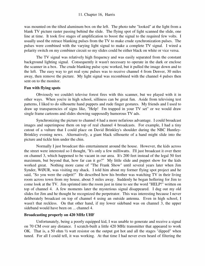
Since TV camera tubes were out of reach, I resorted to using a TV set as a scanner. Large paper or grease-pencil transparencies were taped to the TV tube. A 914 photo-multiplier tube
11. Chapter 16, Harris
was mounted on the tilted aluminum box on the left. The photo tube "looked" at the light from a blank TV picture raster passing behind the slide. The flying spot of light scanned the slide, one line at time. It took five stages of amplification to boost the signal to the required few volts. I usually used the retrace blanking pulses from the TV to make crude synchronization pulses. The pulses were combined with the varying light signal to make a complete TV signal. I wired a polarity switch on my combiner circuit so my slides could be either black on white or vice versa.
The TV signal was relatively high frequency and was easily separated from the constant background lighting signal. Consequently it wasn't necessary to operate in the dark or enclose the scanner in a box. The crude blanking pulse sync worked, but it pulled the image down and to the left. The easy way to get real sync pulses was to receive channel 4 from Denver, 30 miles away, then remove the picture. My light signal was recombined with the channel 4 pulses then sent on to the monitor.
Fun with flying spots
Obviously we couldn't televise forest fires with this scanner, but we played with it in other ways. When you're in high school, silliness can be great fun. Aside from televising test patterns, I liked to do silhouette hand puppets and rude finger gestures. My friends and I used to draw up transparencies of signs like, "Help! I'm trapped in your TV set" or we would draw single frame cartoons and slides showing supposedly humorous TV ads.
Synchronizing the picture to channel 4 had a more nefarious advantage. I could broadcast images and superimpose them on top of real channel 4 broadcasts. For example, I had a tiny cutout of a vulture that I could place on David Brinkley's shoulder during the NBC Huntley-Brinkley evening news. Alternatively, a giant black silhouette of a hand might slide into the picture and tickle him under the chin.
Normally I just broadcast this entertainment around the house. However, the kids across the street were interested so I thought, "It's only a few milliwatts. I'll just broadcast it over there on channel 3, which happened to be vacant in our area. It's 200 feet instead of the legal 50 feet maximum, but beyond that, how far can it go?" My little slide and puppet show for the kids worked great. Nothing more came of "The Frank Show" until several years later when Jim Synder, WØUR, was visiting my shack. I told him about my former flying spot project and he said, "So you were the culprit!" He described how his brother was watching TV in their living room across town from my house, about 5 miles away. Suddenly he began hollering for Jim to come look at the TV. Jim sprinted into the room just in time to see the word "HELP!" written on top of channel 4. A few moments later the mysterious signal disappeared. I dug out my old slides for Jim and he thought he recognized the perpetrator. This was interesting because I never deliberately broadcast on top of channel 4 using an outside antenna. Even in high school, I wasn't that reckless. On that other hand, if my lower sideband was on channel 3, the upper sideband would have been on ... channel 4.
Broadcasting properly on 420 MHz UHF
Unfortunately, being a poorly equipped kid, I was unable to generate and receive a signal on 70 CM over any distance. I scratch-built a little 420 MHz transmitter that appeared to work OK. That is, a 50 ohm ½ watt resistor on the output got hot and all the stages "dipped" when tuned. For all I could tell, it was working. At that time I had never even heard of filtering the

12. Chapter 16, Harris
output with a resonant cavity filter to get rid of the lower sideband, so the vestigial sideband issue was blissfully ignored. That is probably why Jim saw it across town. I also built an alleged 420 MHz converter that received my own signal, although I had no real knowledge of what frequency I was actually sending and receiving. Another barrier was that none of my ham friends were interested in putting up UHF antennas, building converters, and all that. They all were too busy with DX, building kilowatt finals, walkie-talkies, RTTY, and so on. We all had different interests and high school was a busy time.
As you can see, my ham TV project wasn't a complete success. It illustrates the difficulties with homebrew VHF and UHF. To be sure you're producing a quality signal on the right frequency, you need expensive UHF test equipment. Moreover, you need a high level of craftsmanship to control the unwanted oscillations. If 10 meters is tricky, imagine getting 0.70 meters to work right! The only advantages are that you can use low QRP power levels and compensate by building small, high gain antennas. Most of the difficulty with the high HF bands happens when you try to generate high powers over one watt. In contrast, with a small rooftop antenna a few milliwatts of VHF or UHF can get you around town.
In the final analysis, my TV project was loads of fun and I learned plenty. When you scratch-build, the rewards are usually quite different from store-bought ham radio and can be quite unexpected. For example, who would have thought QRP television could work so well?
********************************************************************************
GETTING ON SIXTY METERS
A ham band frontier?
Every generation or so, hams have been granted a new ham band. When 30 meters first opened up, Bob Hamilton, NØRN (former KØIYF), was ready with his homebrew CW transmitter. The bad news was that he was practically the only American on the band. The good news was that 30 meters had been open for years in Europe and suddenly Bob was hot DX. Everyone was calling him. This delightful situation lasted about a year, but as soon as the commercial equipment covered 30 meters, Bob's private DX band became history. After hearing this story I wanted to try out 60 meters when it opened on July 4, 2003.
What 60 meters is
60 Meters consists of five, 2.8 KHz wide channels with center frequencies on 5532, 5348, 5368, 5373 and 5405 KHz. They may be used by General Class and above. The only mode permitted is USB SSB and 50W effective radiated power. ARRL recommends that we set the carrier frequency to 1.5 KHz below the centers of each channel and restrict the audio to between 200 and 2.6 KHz. Unfortunately this band is shared with several other services.
Modifying your present SSB rig
You may already own a 60 meter rig. Bob has a collection of transceivers and set out to put one of them onto 60M. His first try was an old Drake R4 that, with the proper crystal, supposedly "covers everything from 1.8 to 30 MHz." It turned out that the R4 could be used on
any HF frequency except 5.0 to 5.5 MHz. The IF and VFO are in that range and spurious signals would result. Next he tried a Kenwood TS-180. His particular unit was missing a surface-

13. Chapter 16, Harris
mount, broadband filter that needed to have been assembled on a PC board at the factory. It's possible to kludge a filter, but it wouldn't be easy because there is little room for it.
In modern rigs that use VHF IF frequencies, the only barrier preventing transmitting on 5 MHz is the firmware that vetoes illegal frequencies. Bob was able to put his Kenwood TS-50 on 60M by just clipping a diode to reprogram the microprocessor. The miniature Yaesu FT-817 can be modified by tearing the unit apart and soldering and unsoldering some tiny programming jumpers on a board. The Yaesu FT-1000MP was the easiest. He turned off the unit and then turned it back on while holding down two buttons. That brought up a menu that allowed him to select frequency ranges for different regions of the world. At the bottom of the list was "general coverage." This permits operation over the entire spectrum, even on standard broadcast.
A homebrew 60 meter rig
My 60 meter transmitter and receiver converter are shown above. The copper box on the right is the receiver converter. The transmitter consists of 5 main modules: These are a 5 MHz VF0, a frequency converter for the VFO to make a 14 MHz VFO signal, a 9 MHz SSB generator, the mixer/ driver to combine 14MHz with 9 MHz SSB to make 5 MHz SSB and, at the rear, a 50 watt linear amplifier. To get on 60, I added a crystal and 60 meter filters to two of my transmitter modules and I built the receiver converter box. The converter has jumpers all over it because I eventually plan to use it on 6 and 10 meters.
July 4th
2003
I knew 60 meter SSB wouldn't be as much fun as 30 meters, but I naively hoped I might meet some eccentric homebrewers there. As midnight July 3rd approached I tweaked my

14. Chapter 16, Harris
homebrew 60 meter rig on a dummy load. I could hear 4 strong RTTY stations between 5.3 and 5.4 MHz that ran continuously. One of them was parked pretty much on top of channel 2. At 11 p.m., just before the band opened, I found faint SSB stations on all five new channels way down in the noise. I couldn't copy any of them, but they were definitely there under the RTTY and static. They may have been those special-licensed experimental hams or perhaps they were the Coast Guard, far, far away. At 10 minutes after midnight, some relatively loud signals appeared on channel 4. One of them was Milo, NL7SA. These Alaskan hams were gushing about being the first to try out the new band. They said they were using Alaskan CB radios, but for me they were only about Q2-S2. For many years there have been 5 MHz SSB CB channels assigned just for Alaska. I had no graceful opportunity to call them and after a few minutes they faded.
The next night I heard two Alaskan fishermen trading shrimp stew recipes. One recipe featured shrimp, chipped beef and cabbage. Yuk! The other guy said he had just motored 35 miles back from his favorite fishing spot. They never gave call signs, so I believe I was hearing an Alaskan 5 MHz SSB CB channel. After a few days, more and more stateside hams appeared during the evening hours. Channels 1 and 5 had the least RTTY interference and were the most popular. Most guys were using FT1000MPs but I also heard a Kenwood TS-930 and an ICOM 746. Each channel turned into an impromptu "net" with the loudest guy serving as net control. For example, on July 10, Bob, K9CGD, in Longmont, Colorado served as moderator on channel 5 for several hours. As for me, apparently my signal was too puny to get more than a "Sorry old man, you're too weak." For one thing, my antenna is probably inadequate. However, my rig has been successful on four other SSB bands, so I'm mystified about what's wrong.
In conclusion,
60 meters is a band inhabited by RTTY, buzzing data signals, crashing static and two or three channels of weak SSB signals. Basically, it's a whole continent of Yaesu owners trying to get their 60 meter WASs (Worked All States) sharing two or three "party line" channels. After just 7 days, some guys were already claiming as many as 28 states.
When you tune in, you will hear the two loudest guys talking about how neat 60 meters is and that they're going to sign off now so others will have a chance. And ten minutes later the same two guys will still be talking about shutting up, but not actually doing it. The other annoying category is the East Coast guys who are apparently talking to England. But of course, we can't hear England from Colorado and yet it seems impolite to interrupt, even though static is all that's on the channel.
So, what did I learn from getting on 60 meters? I learned that I better be prepared to be disappointed when I start a project and that perhaps I should have done more homework about what units might be the first on the air. I was naive to think I might be among the first. Oh, well, the Alaskan gourmet fishermen were interesting. Hmmmm ... I'm going back to 20 and 30 meter CW. As for something to build, modern ATV still looks interesting. I ought to be able to do a better job this time.
***************************************************************************
HOMEBREWING WITH PICs
By Frank Harris, KØIYE

15. Chapter 16, Harris
Difficult, but still practical
The little ham kits advertised in QST often contain a PIC microcontroller. For example, when a modern ham says he “built a homebrew CW keyer,” what he probably did was buy a kit with a pre-programmed PIC microcomputer and a PC board. There are perhaps 6 or 7 parts that he must solder. Such a kit may produce a great keyer, but it won’t produce much sense of accomplishment. The guy who designed the kit has already enjoyed the homebrew fun, not the guy who buys the kit.
The PIC controllers you find in the kits look simple. They usually have 8, 14 or 20 pins in an old-fashioned DIP package. They look so innocent, how can those little things be hard to program? 20 years ago, microprocessor projects involved building an 8”x 11” PC board full of parts to complete a system. You needed a microprocessor IC, a crystal, EPROM, the RAM, A-to-D converters, D-to-A converters, a modem chip, a timer or two, perhaps some EEPROM and the peripheral interface adapter chips. These ICs were interconnected by busses of 24 different data and address lines. Whew! No wonder microprocessor homebrewing was rare!
The good news about PIC micros is that they do EVERYTHING internally – no giant
PC board is needed. Another neat feature is flash programming – 14K or more. That’s a lot of ROM, really! You can build your project with its own 6 pin interface that allows you to download a new program into it in seconds. Supposedly the programming will last for 40 years, but I doubt I’ll be around long enough to find out. As I recall, the old UV-erasable EPROMs were only good for 10 years.
Selecting the desired pin and feature configuration
The bad news about PICs is that programming them has big challenges: The first obstacle is turning off the wondrous capabilities that you DON’T want. This includes programming nearly every pin on the package to be assigned as a comparator input, voltage reference input, LED driver, analog input, etc, etc. Typically each pin has 3 to 5 possible roles it can serve. These capabilities often interfere with each other. If two capabilities are mutually exclusive, obviously it won’t work.
PIC16F690 development board. A 20 pin PIC version.

16. Chapter 16, Harris
Because of all the capabilities you don’t need, each version of the PIC typically has a 300
page set of datasheets. Also, whatever your application, there’s a PIC processor for every imaginable job. There are literally over a hundred PIC chip variations. Each one of those is available in 5 or 6 different physical packages that are mostly tiny kinds of surface mount. A few years ago electronics parts catalogs were the size of magazines. Today catalogs like Mouser and Digi-Key are the size of the L.A. phone book with thousands of fragile pages. That’s why most people use the on-line catalogs that have built-in search engines to help you find your needle in the haystack. The on-line catalogs are so huge they make the phonebook size catalogs look like abstracts.
Primitive RISC programming
Another odd problem with the PIC is the “reduced instruction set code” (RISC). RISC is often extolled as good, but I’ll be darned if I see why. RISC runs very fast. It allows you to do almost nothing really quickly – up to 20 MHz! It’s like programming the 8008 Intel processor from 1970. There’s just one accumulator, no index register, no divide command, no multiply and no byte test. There are only two simple conditional branch commands that just skip the next
instruction when the carry or zero flag is set. Therefore, every branch needs a “goto” following
the “skip if” command. However, the PIC assembler is quite good. But I’m easy to please. In the bad old days I used to hand-calculate addresses and write out programs in pencil on ruled sheets. Then I Scotch- taped the sheets together to make long scrolls.
In fairness, the PIC professionals use C language programming which bundles huge chunks of RISC programming into clumps usable with a single command. ProBasic for PICs is also popular. Unfortunately, C or Basic programming can’t do all the unique stuff that you need for your project. Therefore, you still have to write some of your own subroutines using RISC machine language. It was obvious to me that I had to master RISC anyway, so my first project was done 100% with RISC.
PIC development systems
PIC development systems consist of a little capsule the size of a playing card that plugs into a USB port. The capsule then plugs into the similar sized sample circuit board on which the PIC is mounted. Once you get launched, you can build the flash programming right into your own project board and you may no longer need the sample development board. Of course if you do that, you may lose the ability to step through programs, read internal registers, and so on. I bought two development systems for about $25 each, one for the PIC16F690 and the other for the more capable PIC16F887.

17. Chapter 16, Harris
The little development boards come with a disk containing zillions of data files, help instructions and example programs. It also includes an editor, a debugger, the assembler and the PIC ROM programmer. It does NOT contain a C or Basic compiler. Compilers range from $150 to $500 or more, depending on which PIC families they are designed for.
The Debugger Program
In theory, the debugger program combines all your functional programs, such as the editor, assembler and even 3rd party compilers, so that they may be operated together “seamlessly.” If you can make it work on your project, I imagine it would be wonderful. You could step through programs, watch constants change, set breakpoints, read internal registers, etc., etc. Sadly, I could never get mine to work. Fortunately, all the parts like the compiler, editor, programmer and so on, can all be called independently, so I pressed on without the debugger. Basically I use lots of trial and error and intuition.
A talking dynamometer
My only PIC project so far has been a talking rope tension meter, (a.k.a, dynamometer), for the rescue group. My original plan was to use the PIC to run a voice synthesizer chip, something like the old “Speak and Spell” Texas Instruments technology. Ironically, the only programmable speech chip I could buy on the Internet was a PIC micro that had been programmed to be a speech synthesizer. Since PICs include multiple oscillators, a modem, D-to-A converters, etc, I shouldn’t have been surprised to find that my programmable speech synthesizer chip was just a programmed PIC microcontroller. Yes, they really are versatile.
It took me weeks to get the serial interface to work. The instructions didn’t mention that the speech synthesizer needed both receive AND transmit lines. There is apparently a “clear to send” confirmation that had to be sent back that wasn’t mentioned in the data sheets. Anyway, I soon had it working as well as it was going to. Sadly, I was the only one who could understand what it was saying. Not good for rescue situations. “Did it say let go of the rope?” ... AHHHHHHHhhhhhhhh … Splash! Apparently not.
A PIC16F887 development board wired into a speech chip programmer. The black plastic programmer unit is plugged into the development board.

18. Chapter 16, Harris
My next attempt used an obsolete American speech recording chip that works well, but has a limited audio frequency response (ISD25120, 1.7 KHz). The speech chip can be hard to understand, but by putting it through a severe hi-pass audio filter, I managed to accentuate its high frequencies and compensate pretty well. But when I tried to buy more speech chips, they were extinct. I finally found a newer chip, the ISD17240, that is superior in every way – except for its modern Serial Peripheral Interface (SPI). Programming that sucker is way beyond what mortals can do with just data sheets and trial and error. Not only must I figure out how to get the PIC to send the instructions and receive the responses, the speech chip has its own complementary SPI digital nightmare I have to decipher. No luck so far. Oh, and by the way, the PIC “weak pull-up” feature for digital input lines is so weak, it’s prone to the slightest noise – use pull up resistors!
In summary,
PIC homebrewing is NOT for people with limited patience and time. It turns out that there is a good reason for buying those little pre-programmed PIC kits – you’ll be done in less than 6 months! On the other hand, if you keep the project simple, such as just directly driving LEDs and reading switches, it’s not so bad. But when you have to talk to other PIC processors or peripheral chips, the fun begins. …. My next project is going to be a CW keyer because it’s basically lights and switches. That’s where I should have started.
*******************************************************************************
CLASS D AUDIO AMPLIFIERS
By Frank Harris, KØIYE
Big hi-fi sound, high efficiency, low voltage
Class D amplifiers chop an analog sinewave signal into a pulse-width-modulated stream of rectangular pulses. In other words, the density of high frequency (400 KHz) rectangular pulses varies with time and represents the amplitude of the wavy simple analog signal. When applied to audio amplification, a chopped series of high frequency square pulses can drive a 4 ohm loudspeaker with surprisingly good fidelity. Because the amplifier output only has two states, the highest voltage and zero voltage, there is no time spent half on and half off. Consequently there
A PIC16F887 breadboard for developing software to drive the speech chip. Note the 6 pin connector on the left used to program the large, 40 pin PIC microcontroller.

19. Chapter 16, Harris
is little power dissipated in the chip. A tiny chip can deliver big power, 1 to 3 watts or more. And it does all this with just 5 volts or less.
Why you might want to use one, or not
Suppose you are building a small, portable battery-powered receiver to go with your QRP transmitter and want to use 6 or 9 volt batteries. If you look at the data sheets for the good old LM388 or LM386 analog amplifiers, you’ll see they are rated to work from 5 to 15 volts. If you are listening with sensitive earphones, a low voltage supply will work fine. On the other hand, if you want audio that’s both Hi-Fi and LOUD, then you’ll discover you need big voltage to go with your 4 inch or larger speaker. Yes, low voltage can be loud with analog chips using just 5 volts and, but the distortion is intolerable.
It is theoretically possible to use op-amps and comparators to build your own Class D audio amplifier. But when you diagram what has to be done, you quickly discover that you would need a huge array of components, a big circuit board and lots of trial and error. Class D amplifiers are the reason other people's tiny cellphones can be so annoying - they're both loud AND hi-fi and they accomplish this with tiny low voltage batteries.
EMI – digital hash in your receiver
If you’ve ever home-built a sensitive ham receiver, you probably discovered that a pulse- width-modulated regulated power supply or even a simple digital display, will make noise in your receiver that destroyed much of the sensitivity you worked so hard to achieve. The class D
audio chips I used, Maxim MAX9719 and MAX9759, have “spread spectrum” PWM systems to reduce EMI. Moreover, you have your choice of 3 different sample frequencies that supposedly make it less likely that the hash will appear outside your desired ham band. Unfortunately, the wires from this board up to my speaker radiated VHF RF noise like crazy. Since my project needed to work around VHF hand-helds, I was relieved to discover that I could silence the racket by stringing 5 large ferrite beads on the speaker wires. Unfortunately, the noise was still unacceptable for use around my HF receiver. Sure, I could still hear the hams over the hiss, but that’s not good enough. Oh, well. At least Class D worked for my immediate application.
And now more bad news
You have probably already noticed that the modern world does not want us to build cool stuff in our basements. The complexity is bad enough. But modern surface mount is providing the coup-de-grace to homebrewers like us. In the old days, chips came in DIP packages with big pins. They have 0.1 inch spacing that we can plug into sockets. Even the early surface mounts weren’t impossible to solder. Yes, 0.50” spacing was a little tight, but the leads stuck out from
Modern chips are often surface mount and really tiny. Even surface mount with projecting leads are becoming scarce. The tool is the tip of a 1.5 mm wood carving gouge used to cut the pads.

20. Chapter 16, Harris
the body of the chip and most of us figured out ways of soldering them. For example, you can buy tiny adapter circuit boards to accept the “SO” surface mount chips. The periphery of the little board has pads big enough to accept reasonable sized wires. I’ve even managed to successfully solder SOs with 0.020” spacing onto the little boards.
Today many of the new chips aren’t available in DIPs or even SOs. When I ordered my Class D amplifiers, I studied the 5 or 6 versions of surface mount and ordered the biggest one. It had no leads that stuck out, but the contacts were at least on the periphery of the tiny squares and I hoped I could solder wires to those.
I was shocked when I opened the package and found tiny square black flakes 4 mm on a side. Using a microscope, I could read the labels on the chips. Yes, those were the “big” versions I had ordered. Sure glad I didn’t get the little ones! The 16 contacts were positioned around the circumference of the chip, but they were just metallic dots. My first reaction was that the project was over. But then I thought: These chips are too cheap to bother sending back. I might as well have a go at it.
How to solder chips you can barely see
First you must give up caffeine and booze. If you have benign familial tremor like some members of my family, I’m sorry, you’re already screwed. I talked about this at the local ham club meeting and I was told that the professional way to solder surface mount is using low temperature solder available in a paste. The paste is applied to the circuit board using a syringe with an extremely fine needle. The chip is then lowered onto its pads and heated with a heat gun. I haven’t tried this, but because of the small size, it isn’t going to be easy, fine gauge needle or not.
Even if I had the solder paste and needle applicator, I would still need the PC board with the tiny traces and pads. I use two methods of making PC boards. For big DIP chips I use perf- boards with pre-drilled holes spaced on 0.1 centers. RF circuits need real printed-style circuit boards to reduce lead inductance. I make crude but effective PC boards using a fine wood gouge to carve off the copper between the traces. I start by gluing the chip down to the PC board with 5 minute Epoxy. Tiny hand-held gouges intended for wood carving are hard to find. I bought mine from www.TraditionalWoodworker.com. “Two Cherries” brand, micro-carving tools are the smallest I’ve found. They have cupped ends as small as 1mm. However, a 1/8” (3mm) V-
Sharpen your soldering tip and set the temperature to 600 degrees. I use 24 gauge solder and stripped wire-wrap wire to make the connections. Bring your iron in radially as shown and solder quickly before you fry the chip.
21. Chapter 16, Harris
parting gouge can be made to work.
Next, you’ll need a really fine-tipped, temperature controlled soldering iron. I use a Weller model WES51. I filed the tip to make it as sharp as possible. Also, the solder needs to be the thinnest you can find. I use 0.022” (24 gauge) diameter solder. I use stripped wire-wrap wire, about 30 gauge, to contact the chip pads. I solder the easy end of the jumper first onto the big pads and then bend the tiny wire down into position over the tiny dot. You have to solder each contact as swiftly and deftly as possible. You might want to practice before you ruin too many chips. The higher the temperature, the easier it is to make the contact, but the more likely you’ll kill the chip – a bit of a dilemma there. 600 degrees seems to be a good compromise.
My class D amplifier board
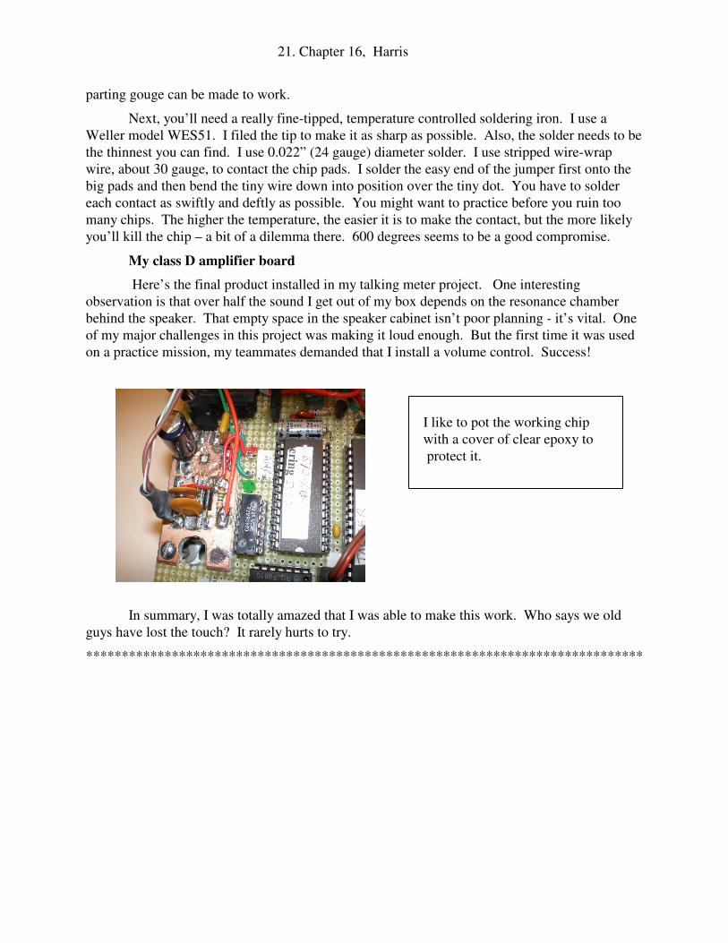
Here’s the final product installed in my talking meter project. One interesting observation is that over half the sound I get out of my box depends on the resonance chamber behind the speaker. That empty space in the speaker cabinet isn’t poor planning - it’s vital. One of my major challenges in this project was making it loud enough. But the first time it was used on a practice mission, my teammates demanded that I install a volume control. Success!
In summary, I was totally amazed that I was able to make this work. Who says we old guys have lost the touch? It rarely hurts to try.
******************************************************************************
I like to pot the working chip with a cover of clear epoxy to protect it.