Chapter 15 HW Solution - Mechanical Engineeringstarr/teaching/me314/chpt15soln.pdfChapter 15 HW...
4
ME 314 Chapter 6 HW May 4, 2009 Chapter 15 HW Solution Problem 15.2: A sketch of the “weldment” is shown below. We need to find the mass moment of inertia around an axis through the center of the small hole. The moments of inertia of both a rectangular prism (bar) and a round disk are in Appendix A, Table 5, on text p. 715. Both of these are also shown above. The parts are steel, and the density of steel is given. The procedure for both the bar and disk(s) are the same: first find the moment of inertia about the mass center, then use the parallel-axis theorem to find the moment of inertia about the desired axis. Bar. From Appendix A the desired moment of inertia is I y , and the expression is I y = m ( a 2 + c 2 ) 12 (1) The volume of the bar is V bar = 75, 000 mm 3 (2) thus its mass is m bar = V bar ρ =0.5850 kg (3) The mass moments of inertia about an axis perpendicular to the bar and through its center of mass and then through the desired axis (distance d =0.125 m) are I cm =0.004509375 kg-m 2 (4) I axis = I cm + m bar d 2 =0.01365 kg-m 2 (5) Disk. From Appendix A the desired moment of inertia is I x , which is I x = mr 2 2 (6) The volume of the disk is V disk = 39, 270 mm 3 (7) thus its mass is m bar = V bar ρ =0.306305 kg (8) The mass moments of inertia about an axis perpendicular to the disk and through its center of mass and then through the desired axis (distance d =0.250 m) are I cm =9.57204 × 10 -5 kg-m 2 (9) I axis = I cm + m bar d 2 =0.0192398 kg-m 2 (10)
Transcript of Chapter 15 HW Solution - Mechanical Engineeringstarr/teaching/me314/chpt15soln.pdfChapter 15 HW...

ME 314 Chapter 6 HW May 4, 2009
Chapter 15 HW Solution
Problem 15.2: A sketch of the “weldment” is shown below. We need to find the mass moment of inertia around anaxis through the center of the small hole.
The moments of inertia of both a rectangular prism (bar) and a round disk are in Appendix A, Table 5, on text p.715. Both of these are also shown above. The parts are steel, and the density of steel is given. The procedure for boththe bar and disk(s) are the same: first find the moment of inertia about the mass center, then use the parallel-axistheorem to find the moment of inertia about the desired axis.
Bar. From Appendix A the desired moment of inertia is Iy, and the expression is
Iy =m(a2 + c2
)12
(1)
The volume of the bar is
Vbar = 75, 000 mm3 (2)
thus its mass is
mbar = Vbarρ = 0.5850 kg (3)
The mass moments of inertia about an axis perpendicular to the bar and through its center of mass and then throughthe desired axis (distance d = 0.125 m) are
Icm = 0.004509375 kg-m2 (4)
Iaxis = Icm +mbard2 = 0.01365 kg-m2 (5)
Disk. From Appendix A the desired moment of inertia is Ix, which is
Ix =mr2
2(6)
The volume of the disk is
Vdisk = 39, 270 mm3 (7)
thus its mass is
mbar = Vbarρ = 0.306305 kg (8)
The mass moments of inertia about an axis perpendicular to the disk and through its center of mass and then throughthe desired axis (distance d = 0.250 m) are
Icm = 9.57204× 10⁻⁵ kg-m2 (9)
Iaxis = Icm +mbard2 = 0.0192398 kg-m2 (10)
ME 314 Chapter 6 HW May 4, 2009
Complete Part. Just sum the bar plus two disks, so
mtotal = mbar + 2mdisk = 1.198 kg (11)
Itotal = Ibar + 2Idisk = 0.05213 kg-m2 (12)
Acceleration and Required Torque. The specified acceleration was α = 100 rpm/s, which is
α =100 revmin-s
× 2π radrev
× min60 sec
= 10.472radsec2
(13)
The required torque M is
M = Itotalα = 0.5459 N-m = 545.9 N-mm, (these are the units ADAMS will use) (14)
ADAMS Simulation. I constructed this part in ADAMS and applied the exact moment calculated in (14)—I’llshow this in class. I let the simulation run for 1.00 seconds. For the stated acceleration, the angle at the end of 1.00seconds should be
θ(t) =12θ̈t2 =⇒ θ(1.00) =
10.4722
(1)2 = 5.236 rad = 300◦ (15)
A plot of the ADAMS simulation of the angle and angular speed are shown below.
1.00.80.60.40.20.0
360
270
180
90
0
100
80
60
40
20
0
Joint Angle and Speed in Degrees and RPMApplied Torque of 545.9 N-mm
Time (sec)
Angl
e (d
eg)
Angu
lar S
peed
(rpm
)
Joint Angle (deg)Joint Velocity (rpm)
At the end of 1.00 seconds the angle is exactly 300◦, so the calculated moment based on the moment of inertia musthave been correct! Science is wonderful.

ME 314 Chapter 6 HW May 4, 2009
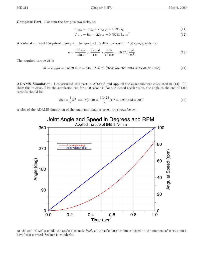
Problem 15.6: The problem statement is shown at right. Thisis a slider-crank mechanism with an applied force FB on thepiston (slider). The crank is rotating at a constant angularvelocity of ω2 = 160 k rad/s, which is about 1,530 rpm—that’snot terribly fast, but it might be typical of a good-sized dieselengine.
In approaching this mechanism, it turns out that you cannotsolve link 4 by itself, but when you consider links 3 & 4 togetheryou’ll have 5 equations in 5 unknowns, which you can solve.Then link 2 is easy to analyze after that.
You do have to find φ, the angle of the connecting rod AB fromhorizontal; using the law of sines (or a loop closure equation),
φ = sin−1
(3 sin 30◦
12
)= 7.1808◦
Free Body Diagrams. The free-body diagrams are shown below. You know the directions of FB and F14 (nofriction, so it’s normal), but no other forces.
Link 4: The force balance on link 4 is
FB + F14 + F34 = m4aG4 ,
which yields two scalar equations:
i : F x34 = m4a
xG4
+ 800 (16)j : F y
14 + F y34 = 0. (17)
There is no moment balance on link 4. Equations (16) and (17) clearly cannot be solved for the three unknowns inthem, so we must continue on...
Link 3: The force balance on link 3 is
F23 + F43 = m3aG3 =⇒ F23 +− (F34) = m3aG3 ,
which again yields two scalar equations:
i : F x23 − F x
34 = m3axG3
(18)j : F y
23 − Fy34 = m3a
yG3
(19)
The moment balance on link 3 (around center of mass G3) is
rAG3 × F23 + rBG3 × (−F34) = IG3α3 (20)
Equation (20) yields only a “k” equation, so we now have 5 equations in 5 unknowns, and this can be solved.
ME 314 Chapter 6 HW May 4, 2009
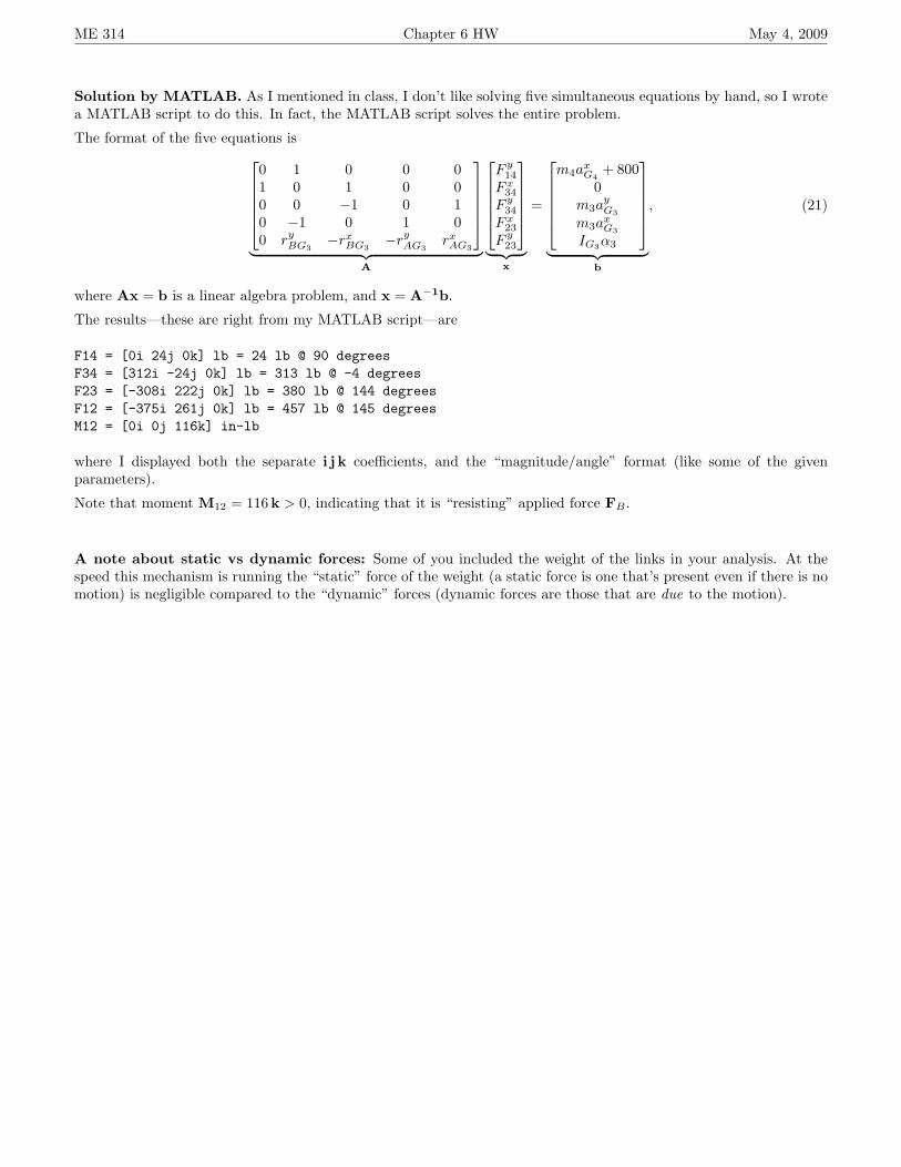
Solution by MATLAB. As I mentioned in class, I don’t like solving five simultaneous equations by hand, so I wrotea MATLAB script to do this. In fact, the MATLAB script solves the entire problem.
The format of the five equations is0 1 0 0 01 0 1 0 00 0 −1 0 10 −1 0 1 00 ry
BG3−rx
BG3−ry
AG3rxAG3
︸ ︷︷ ︸
A
F y
14
F x34
F y34
F x23
F y23
︸ ︷︷ ︸
x
=
m4a
xG4
+ 8000
m3ayG3
m3axG3
IG3α3
︸ ︷︷ ︸
b
, (21)
where Ax = b is a linear algebra problem, and x = A−1b.
The results—these are right from my MATLAB script—are
F14 = [0i 24j 0k] lb = 24 lb @ 90 degreesF34 = [312i -24j 0k] lb = 313 lb @ -4 degreesF23 = [-308i 222j 0k] lb = 380 lb @ 144 degreesF12 = [-375i 261j 0k] lb = 457 lb @ 145 degreesM12 = [0i 0j 116k] in-lb
where I displayed both the separate i j k coefficients, and the “magnitude/angle” format (like some of the givenparameters).
Note that moment M12 = 116 k > 0, indicating that it is “resisting” applied force FB .
A note about static vs dynamic forces: Some of you included the weight of the links in your analysis. At thespeed this mechanism is running the “static” force of the weight (a static force is one that’s present even if there is nomotion) is negligible compared to the “dynamic” forces (dynamic forces are those that are due to the motion).