ME314 CMM Procedure, Updated 2/22/07 -...
53
ME314 CMM Procedure, Updated 4/12/07 Starting the CMM 1. Remove plastic cover
Transcript of ME314 CMM Procedure, Updated 2/22/07 -...

ME314 CMM Procedure, Updated 4/12/07
Starting the CMM
1. Remove plastic cover
2. Retrieve probe head and probe
1. Unlock cabinet
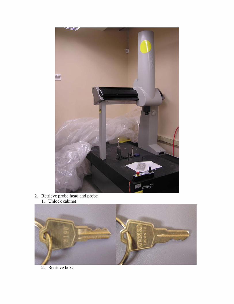
2. Retrieve box.
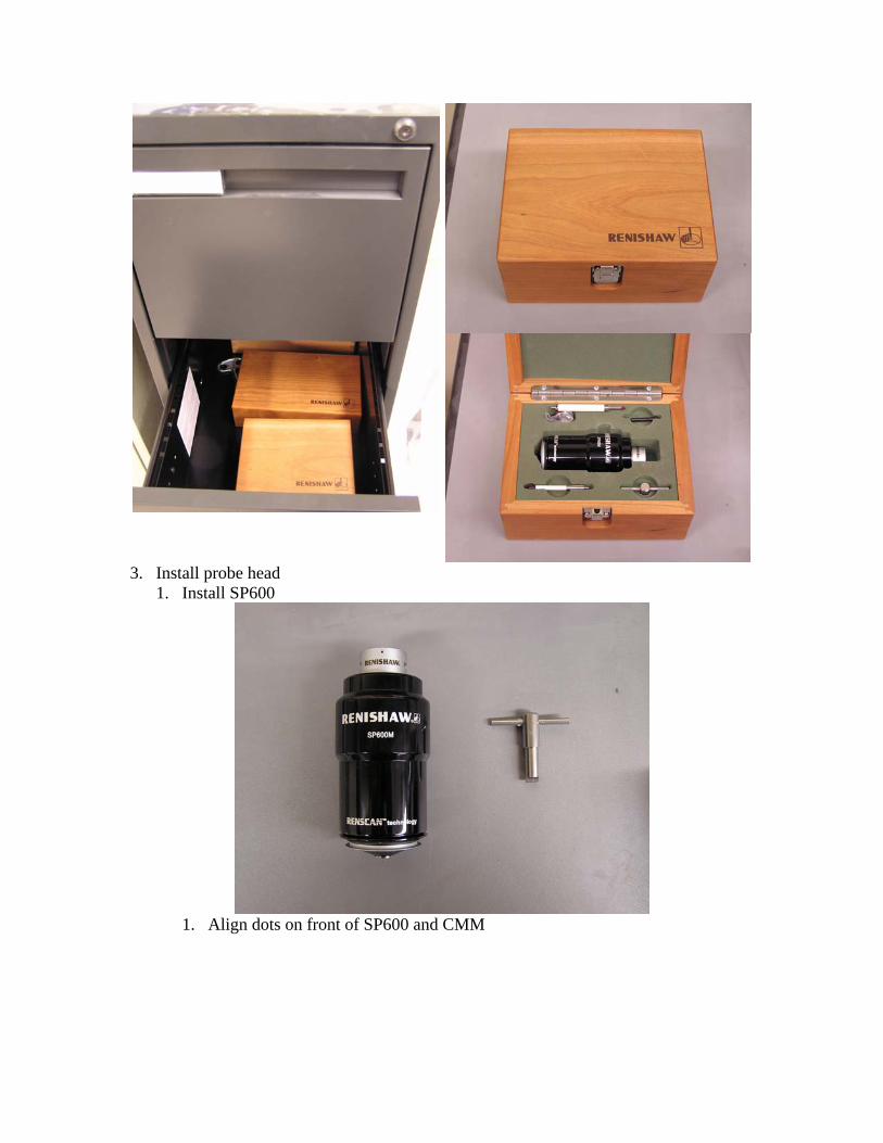
3. Install probe head 1. Install SP600
1. Align dots on front of SP600 and CMM
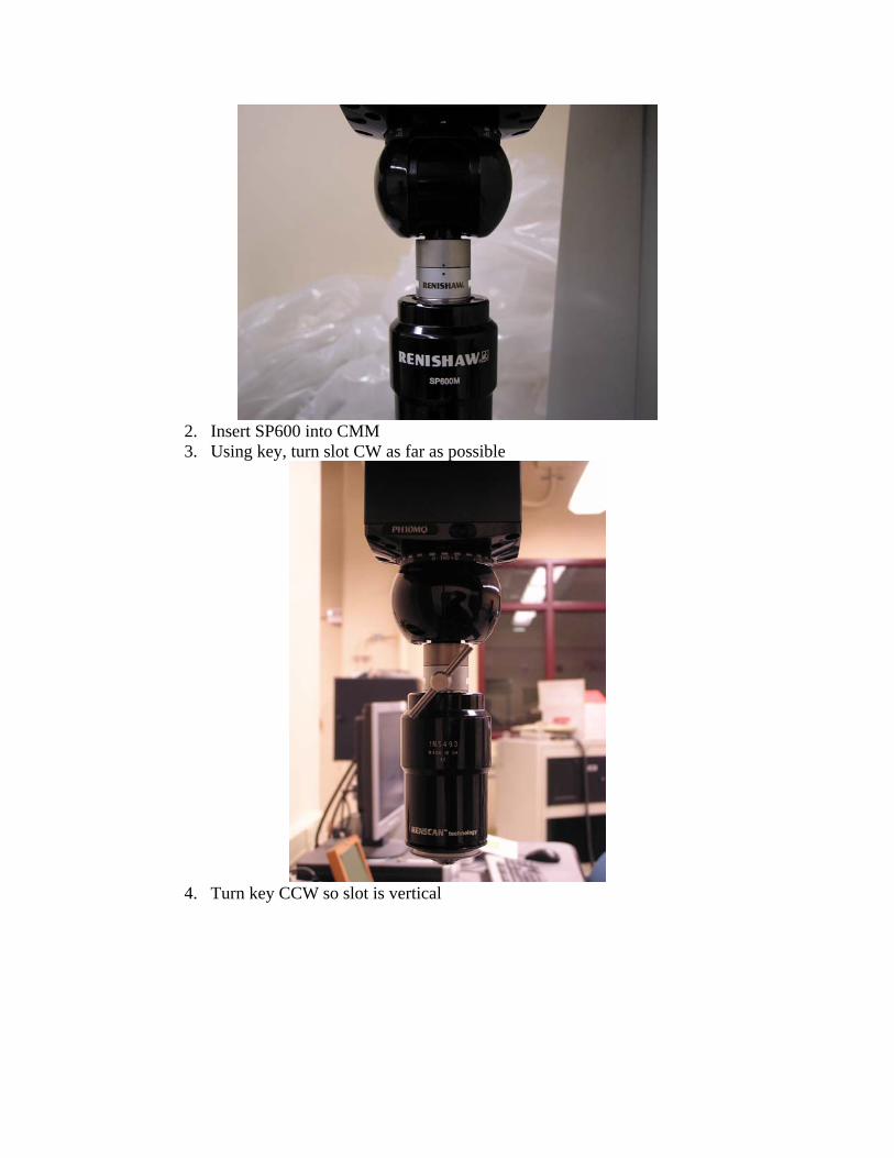
2. Insert SP600 into CMM 3. Using key, turn slot CW as far as possible
4. Turn key CCW so slot is vertical
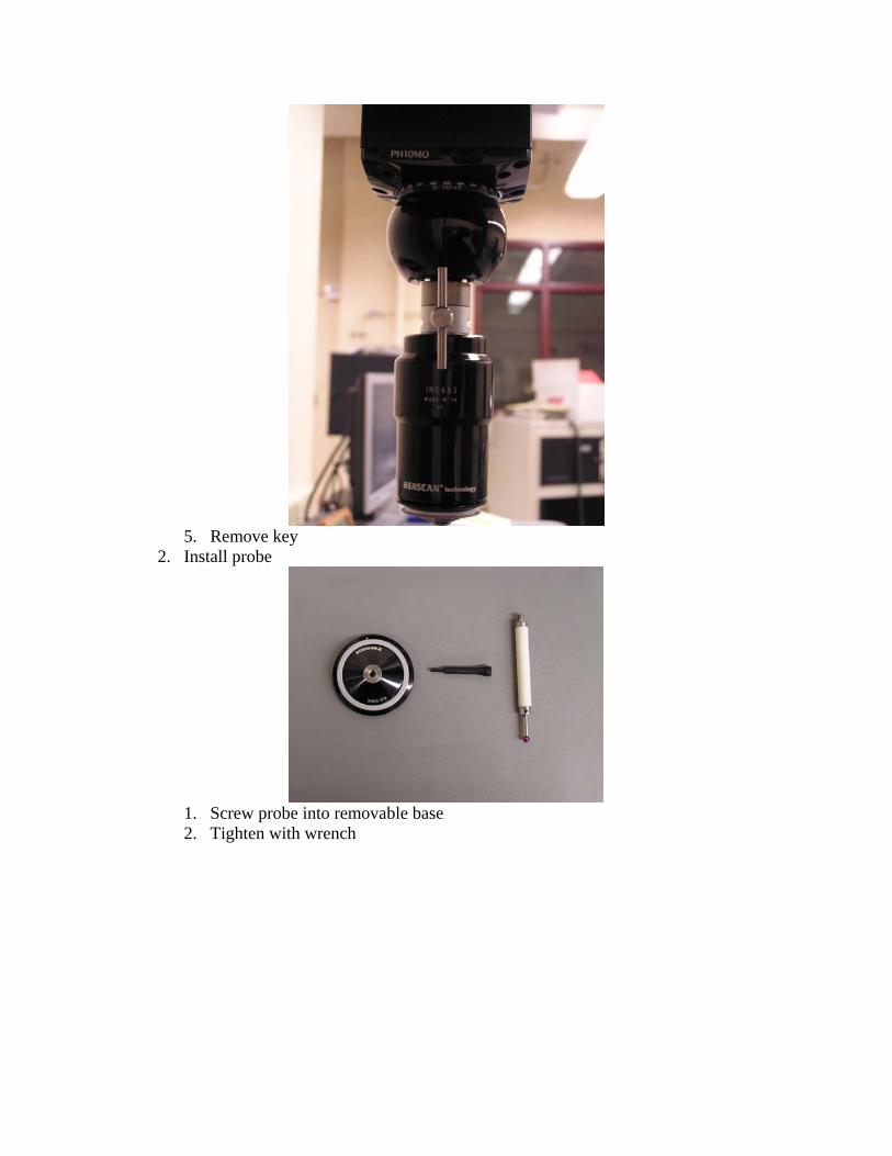
5. Remove key
2. Install probe
1. Screw probe into removable base 2. Tighten with wrench
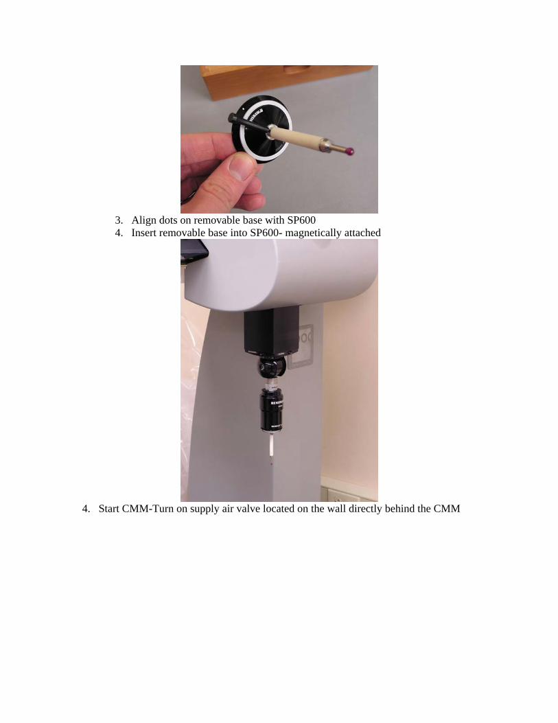
3. Align dots on removable base with SP600 4. Insert removable base into SP600- magnetically attached
4. Start CMM-Turn on supply air valve located on the wall directly behind the CMM
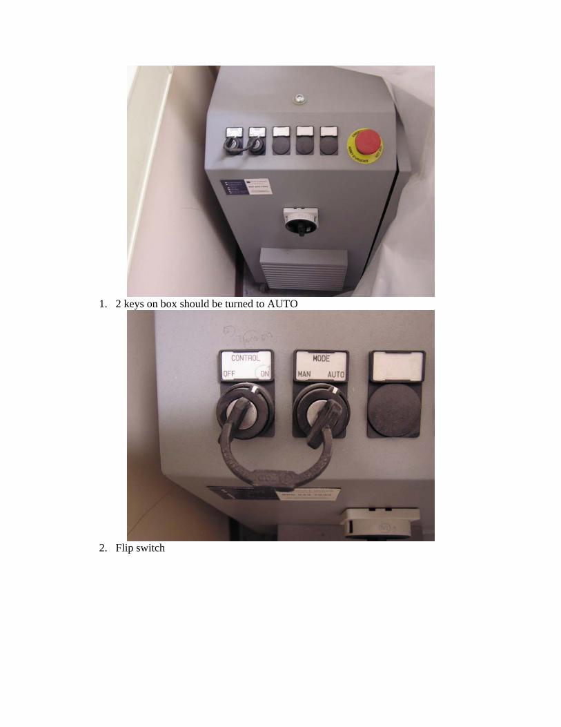
1. 2 keys on box should be turned to AUTO
2. Flip switch
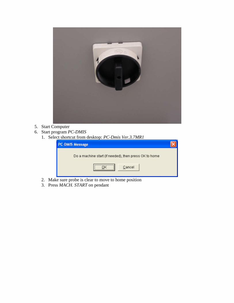
5. Start Computer 6. Start program PC-DMIS
1. Select shortcut from desktop: PC-Dmis Ver.3.7MR1
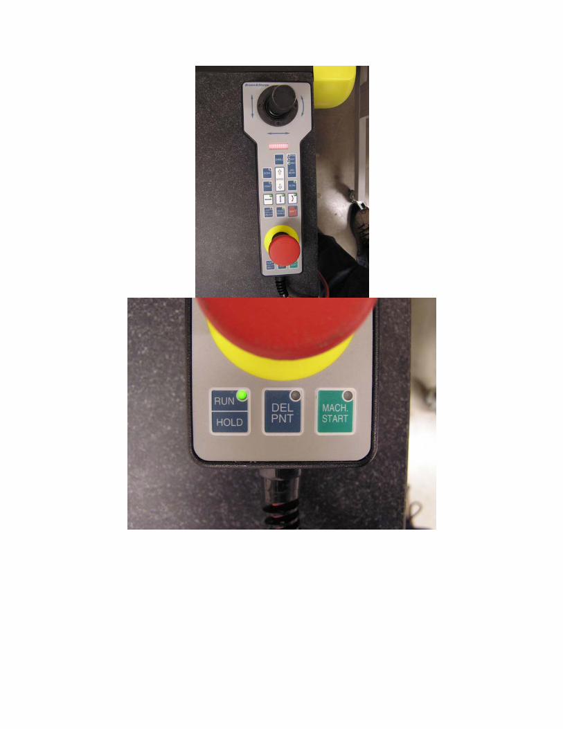
2. Make sure probe is clear to move to home position 3. Press MACH. START on pendant
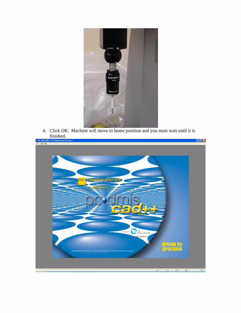
4. Click OK. Machine will move to home position and you must wait until it is
finished.
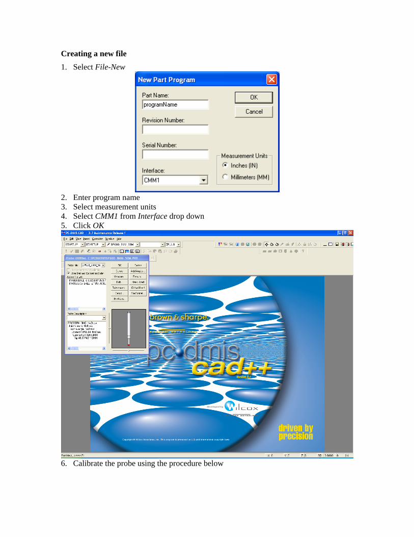
Creating a new file 1. Select File-New
2. Enter program name 3. Select measurement units 4. Select CMM1 from Interface drop down 5. Click OK
6. Calibrate the probe using the procedure below
Opening a saved file 1. Select File-Open 2. Calibrate the probe using the procedure below
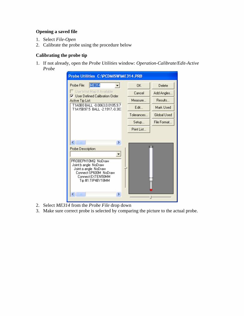
Calibrating the probe tip 1. If not already, open the Probe Utilities window: Operation-Calibrate/Edit-Active
Probe
2. Select ME314 from the Probe File drop down 3. Make sure correct probe is selected by comparing the picture to the actual probe.
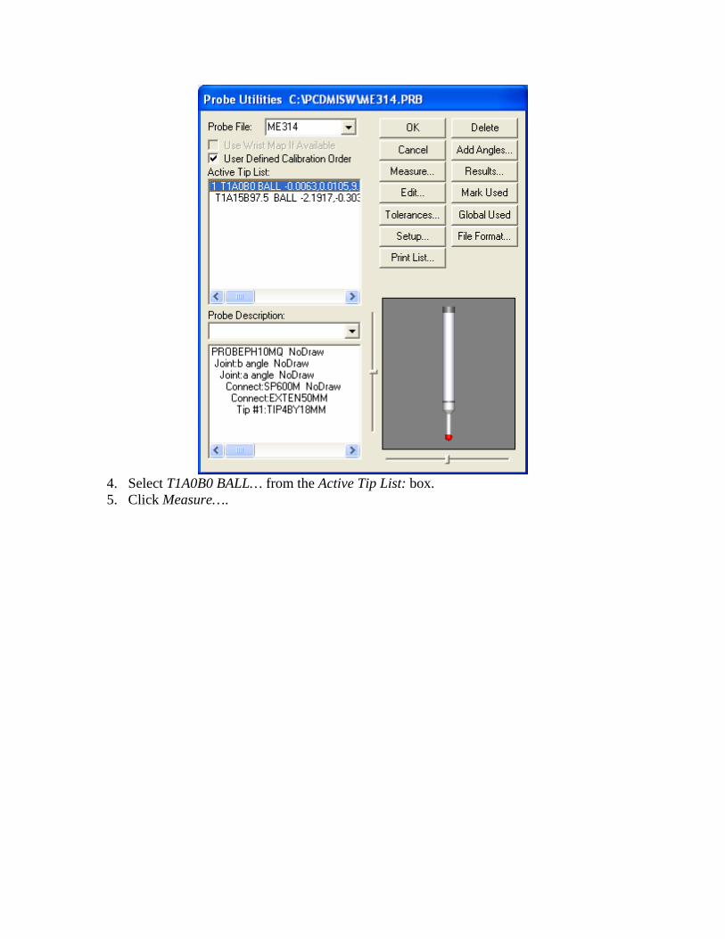
4. Select T1A0B0 BALL… from the Active Tip List: box. 5. Click Measure….
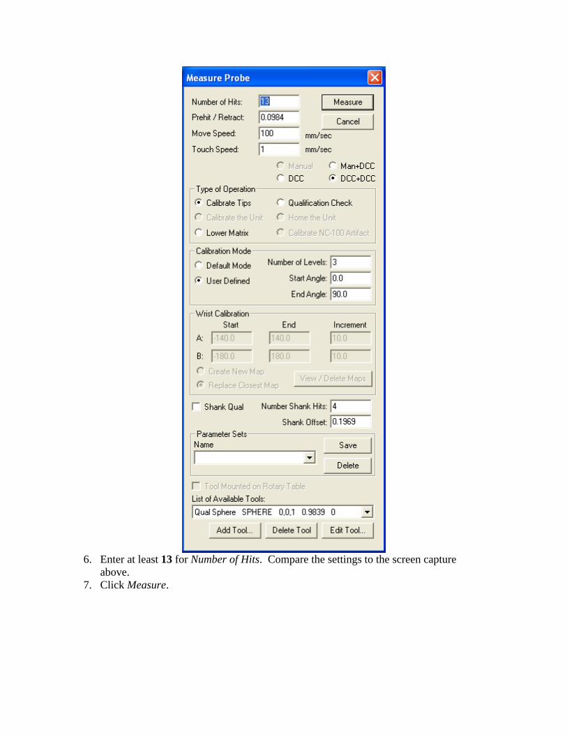
6. Enter at least 13 for Number of Hits. Compare the settings to the screen capture
above. 7. Click Measure.
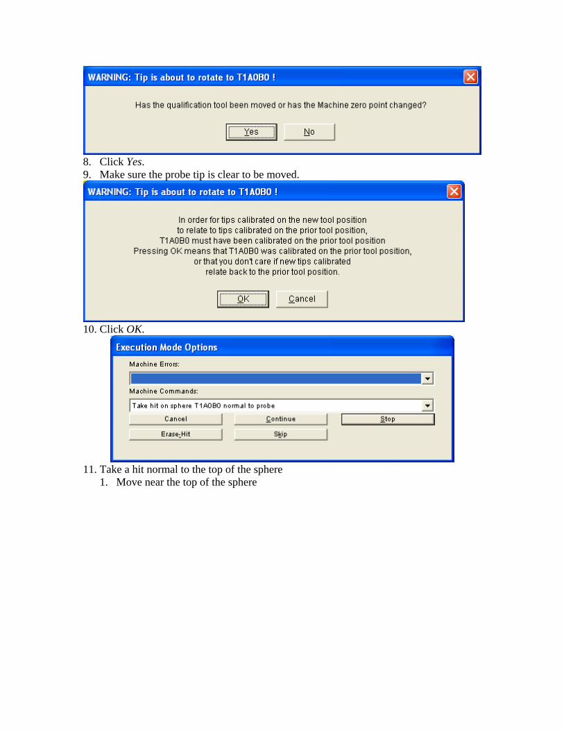
8. Click Yes. 9. Make sure the probe tip is clear to be moved.
10. Click OK.
11. Take a hit normal to the top of the sphere
1. Move near the top of the sphere
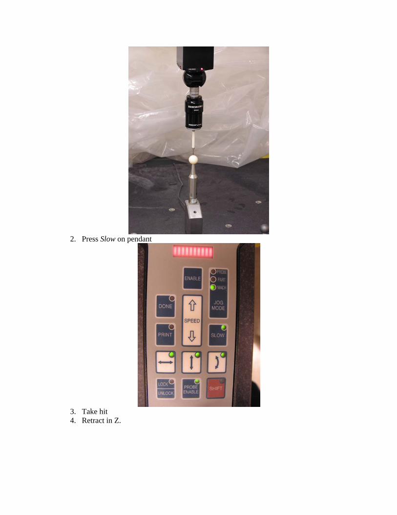
2. Press Slow on pendant
3. Take hit 4. Retract in Z.
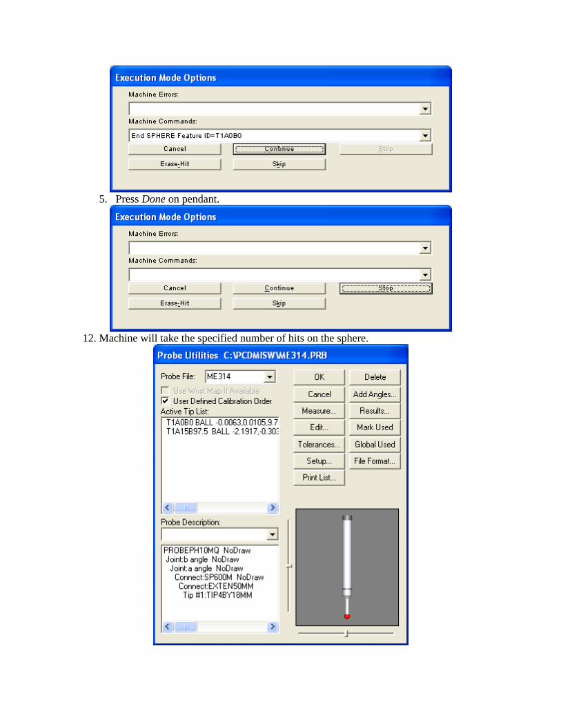
5. Press Done on pendant.
12. Machine will take the specified number of hits on the sphere.
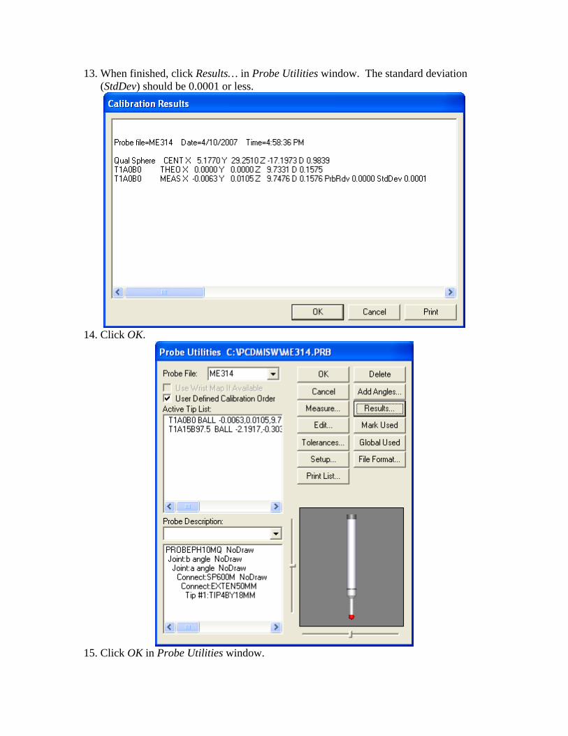
13. When finished, click Results… in Probe Utilities window. The standard deviation (StdDev) should be 0.0001 or less.
14. Click OK.
15. Click OK in Probe Utilities window.
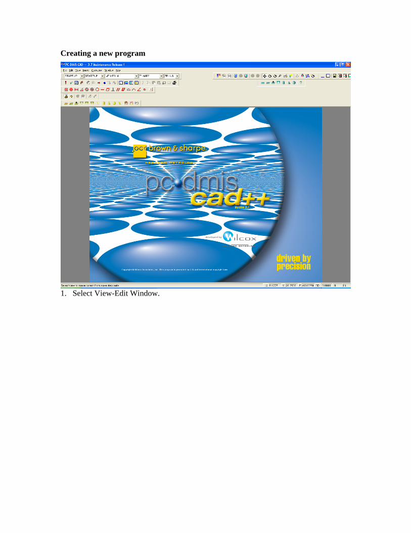
Creating a new program
1. Select View-Edit Window.
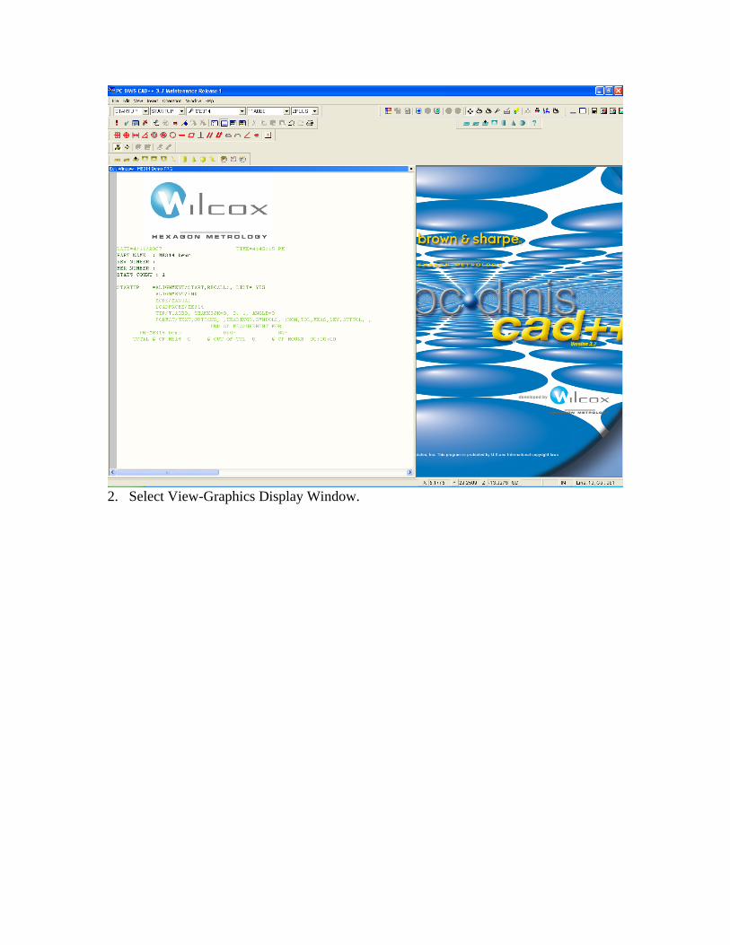
2. Select View-Graphics Display Window.
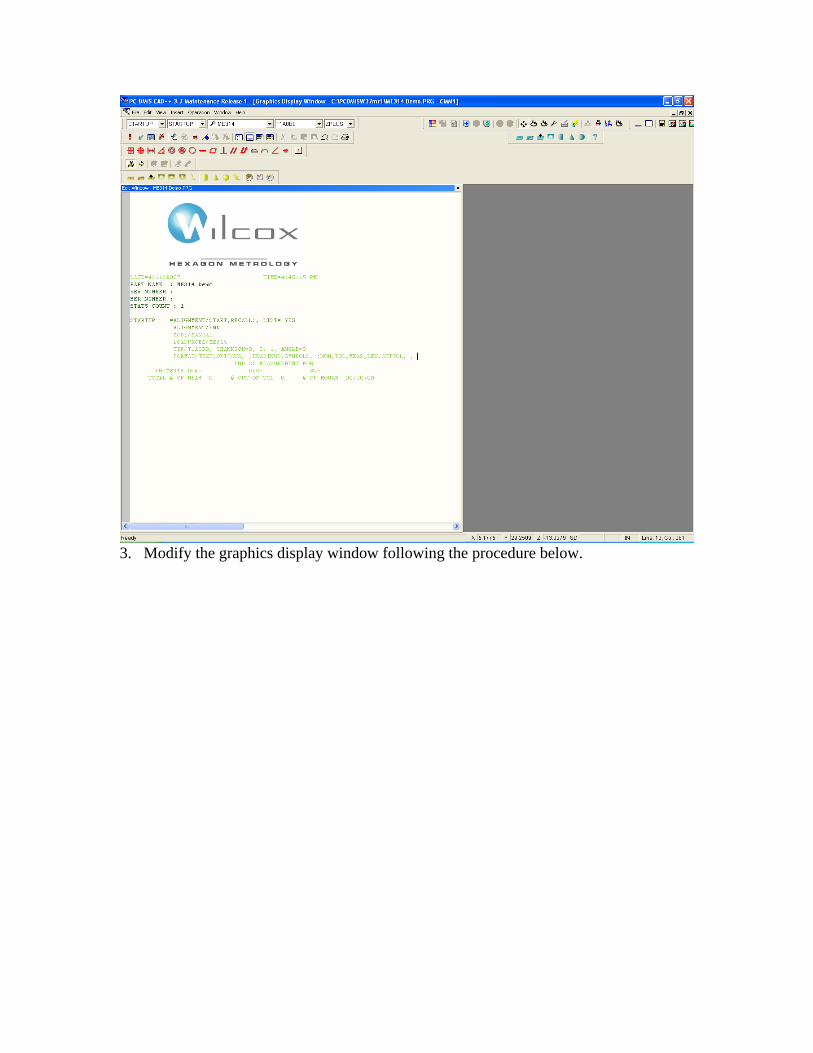
3. Modify the graphics display window following the procedure below.
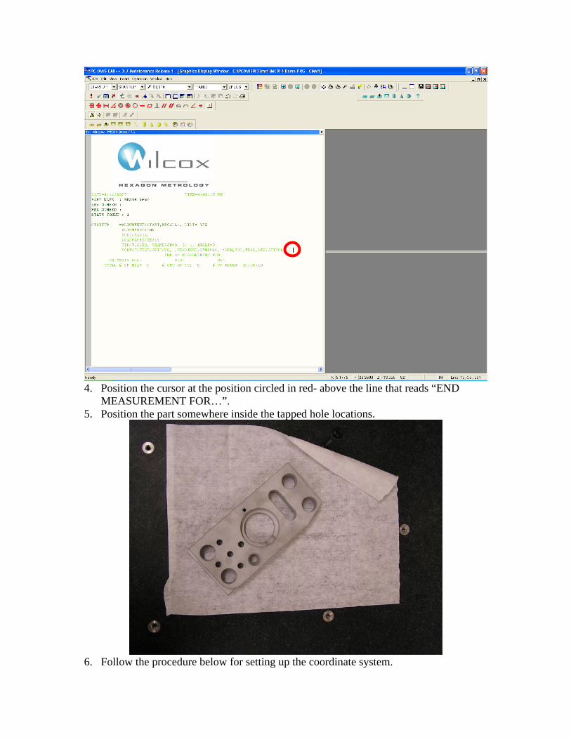
4. Position the cursor at the position circled in red- above the line that reads “END
MEASUREMENT FOR…”. 5. Position the part somewhere inside the tapped hole locations.
6. Follow the procedure below for setting up the coordinate system.
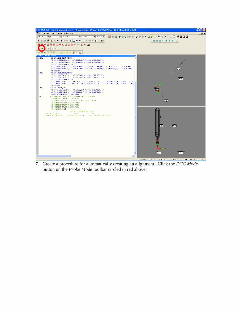
7. Create a procedure for automatically creating an alignment. Click the DCC Mode
button on the Probe Mode toolbar circled in red above.
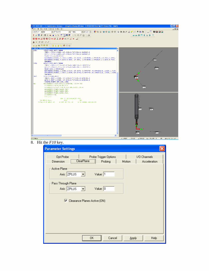
8. Hit the F10 key.
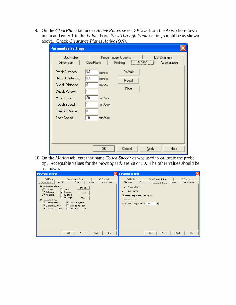
9. On the ClearPlane tab under Active Plane, select ZPLUS from the Axis: drop-down menu and enter 1 in the Value: box. Pass Through Plane setting should be as shown above. Check Clearance Planes Active (ON).
10. On the Motion tab, enter the same Touch Speed: as was used to calibrate the probe
tip. Acceptable values for the Move Speed: are 20 or 50. The other values should be as shown.
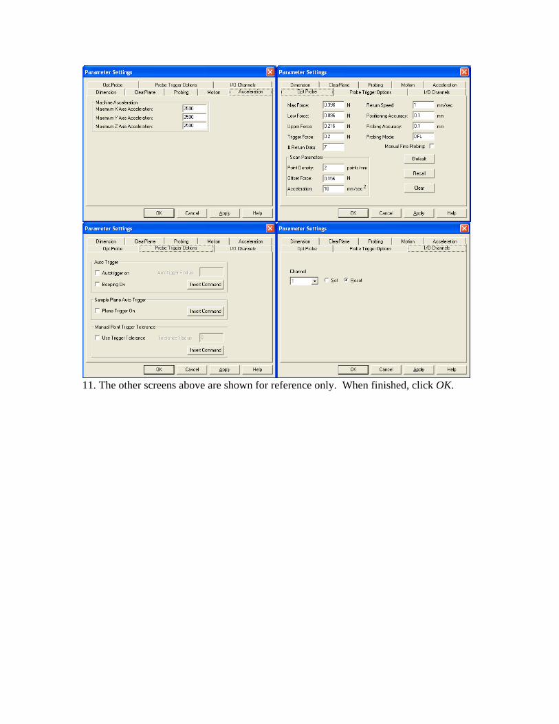
11. The other screens above are shown for reference only. When finished, click OK.
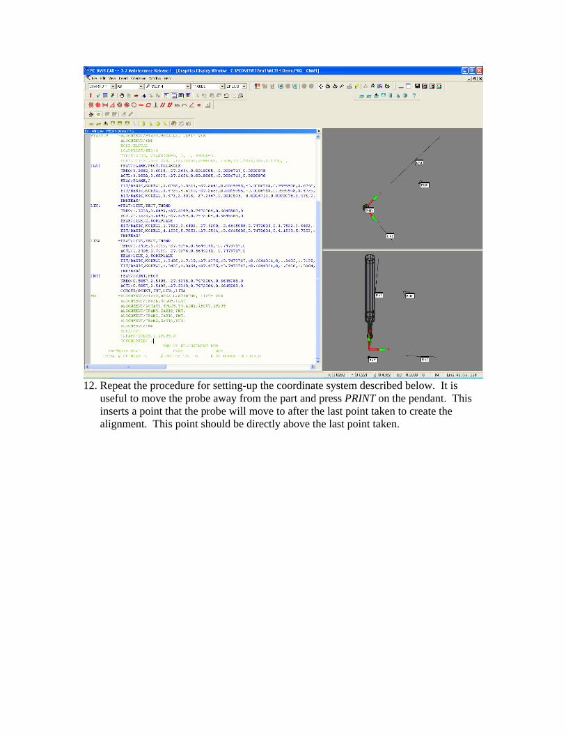
12. Repeat the procedure for setting-up the coordinate system described below. It is
useful to move the probe away from the part and press PRINT on the pendant. This inserts a point that the probe will move to after the last point taken to create the alignment. This point should be directly above the last point taken.
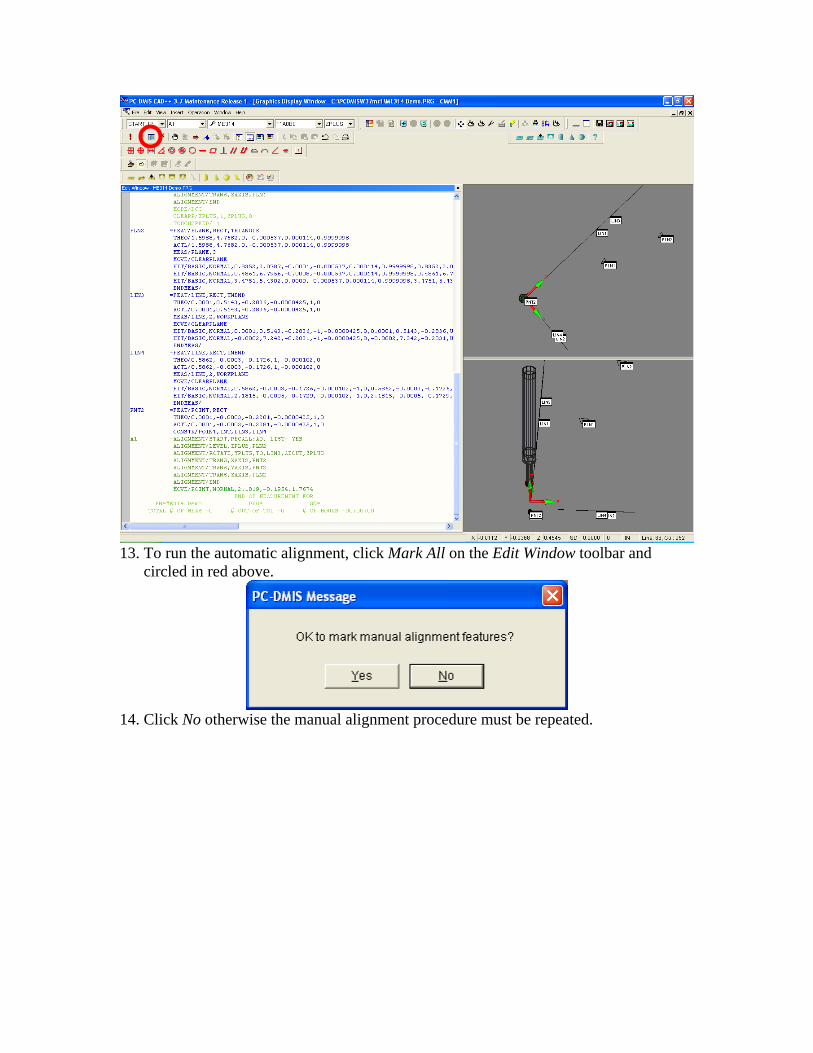
13. To run the automatic alignment, click Mark All on the Edit Window toolbar and
circled in red above.
14. Click No otherwise the manual alignment procedure must be repeated.
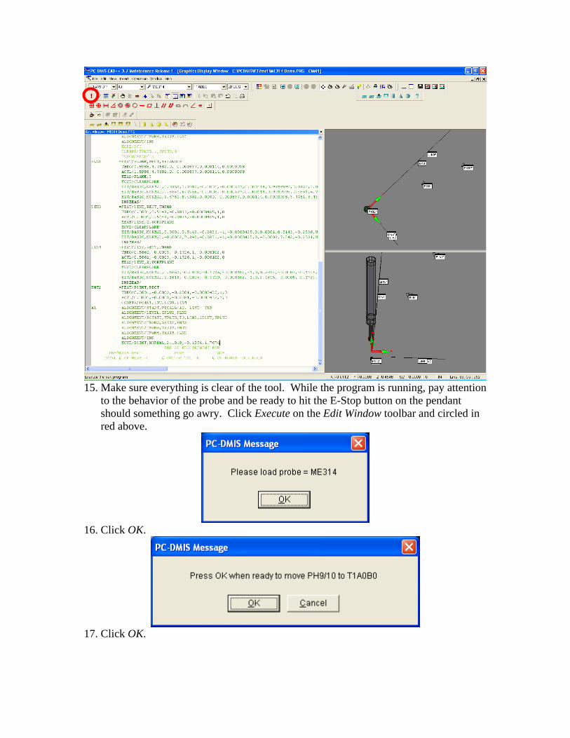
15. Make sure everything is clear of the tool. While the program is running, pay attention
to the behavior of the probe and be ready to hit the E-Stop button on the pendant should something go awry. Click Execute on the Edit Window toolbar and circled in red above.
16. Click OK.
17. Click OK.
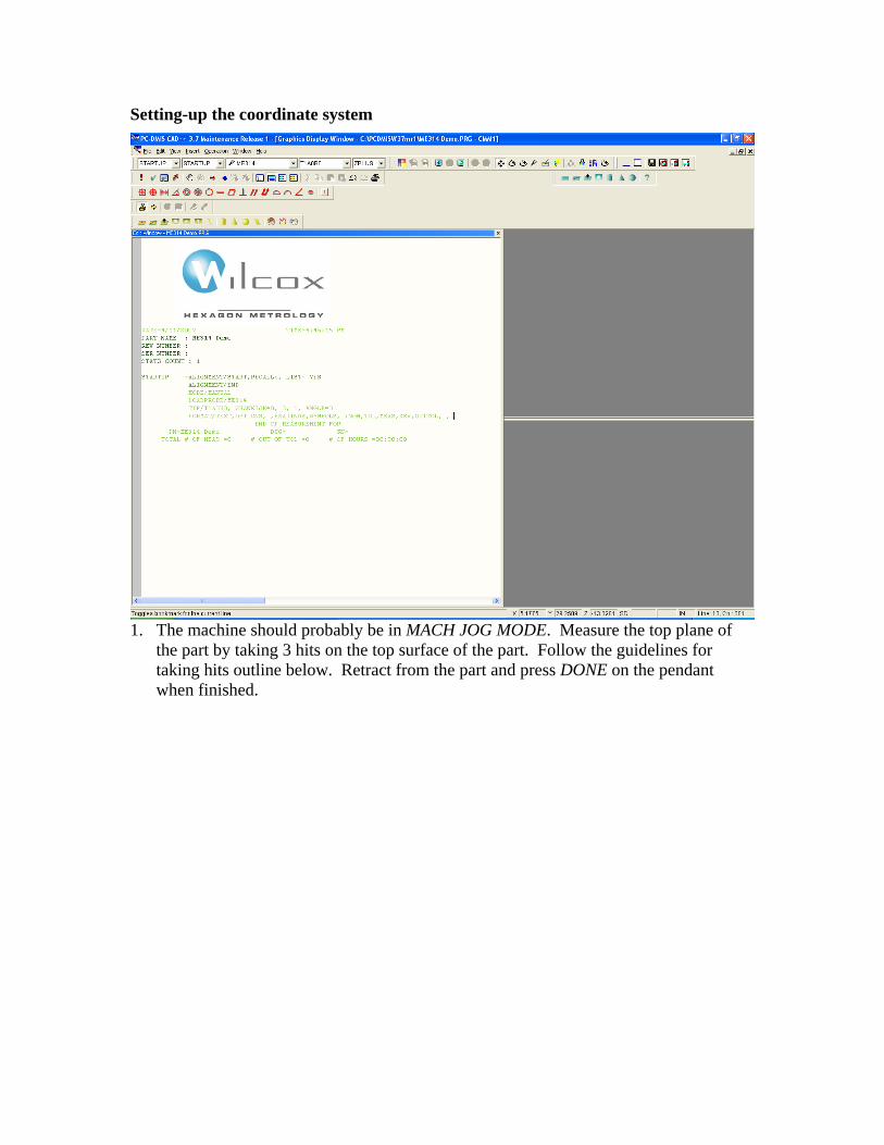
Setting-up the coordinate system
1. The machine should probably be in MACH JOG MODE. Measure the top plane of
the part by taking 3 hits on the top surface of the part. Follow the guidelines for taking hits outline below. Retract from the part and press DONE on the pendant when finished.
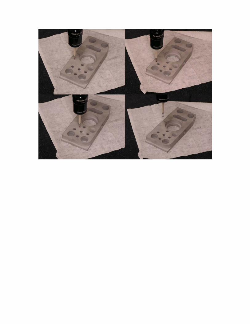
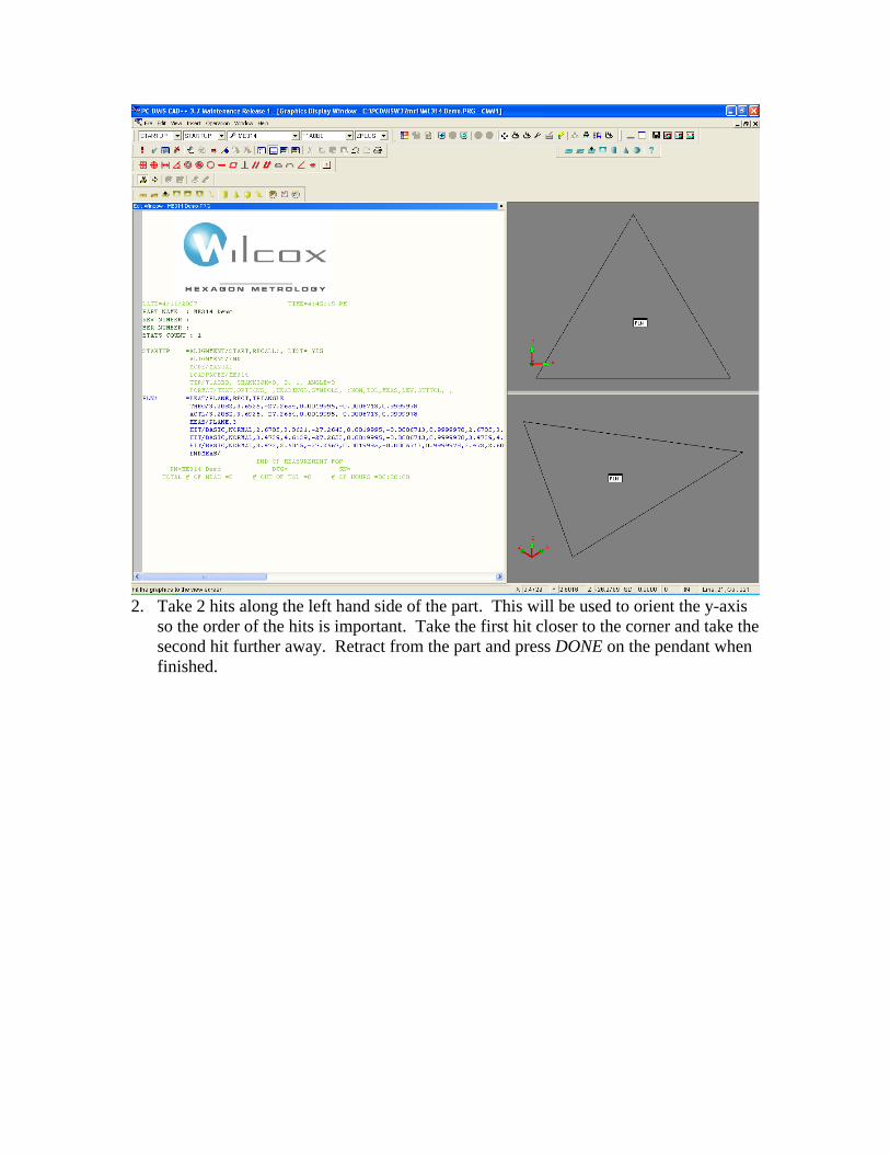
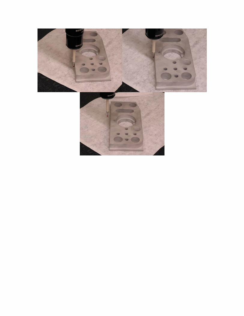
2. Take 2 hits along the left hand side of the part. This will be used to orient the y-axis
so the order of the hits is important. Take the first hit closer to the corner and take the second hit further away. Retract from the part and press DONE on the pendant when finished.
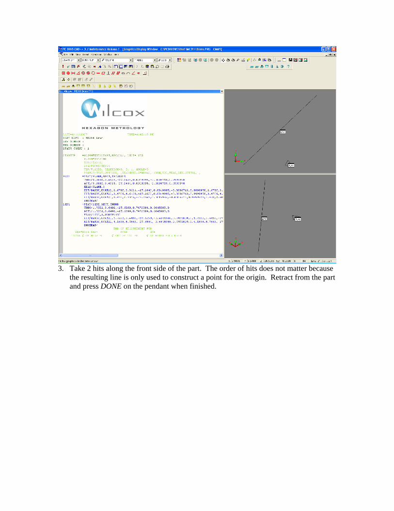
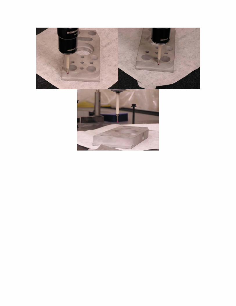
3. Take 2 hits along the front side of the part. The order of hits does not matter because
the resulting line is only used to construct a point for the origin. Retract from the part and press DONE on the pendant when finished.
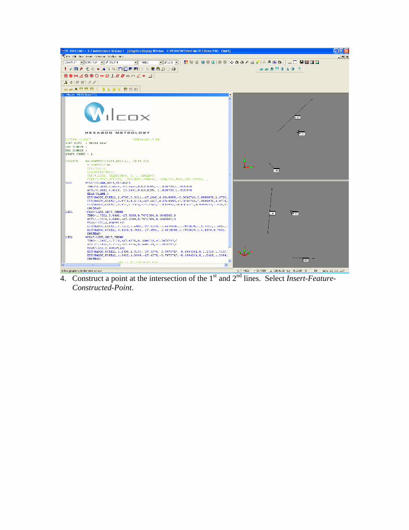
4. Construct a point at the intersection of the 1st and 2nd lines. Select Insert-Feature-
Constructed-Point.
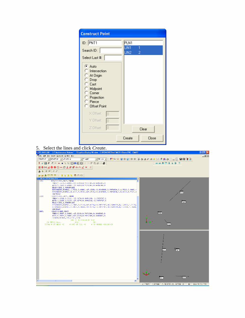
5. Select the lines and click Create.
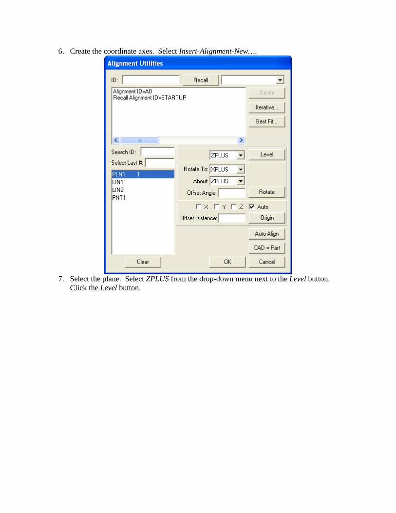
6. Create the coordinate axes. Select Insert-Alignment-New….
7. Select the plane. Select ZPLUS from the drop-down menu next to the Level button.
Click the Level button.
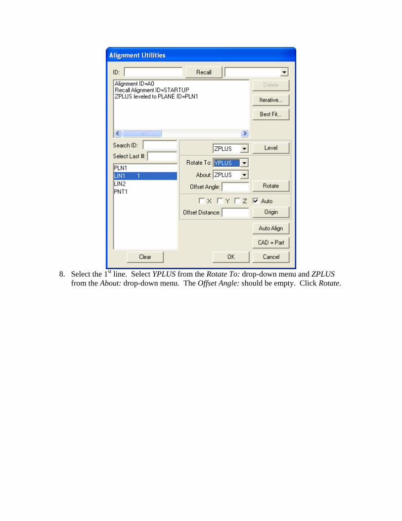
8. Select the 1st line. Select YPLUS from the Rotate To: drop-down menu and ZPLUS
from the About: drop-down menu. The Offset Angle: should be empty. Click Rotate.
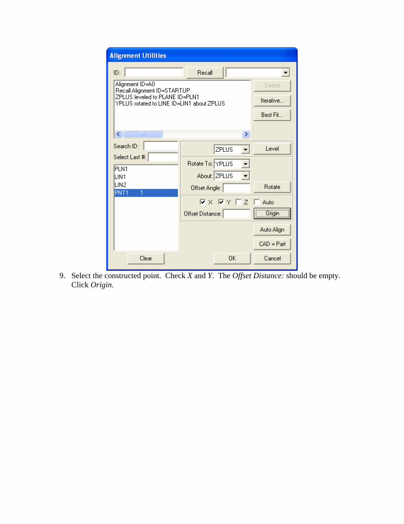
9. Select the constructed point. Check X and Y. The Offset Distance: should be empty.
Click Origin.
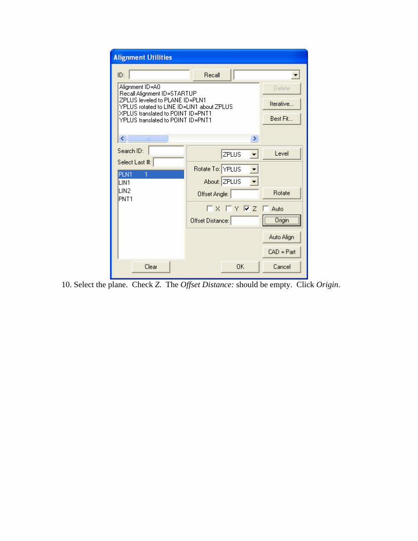
10. Select the plane. Check Z. The Offset Distance: should be empty. Click Origin.
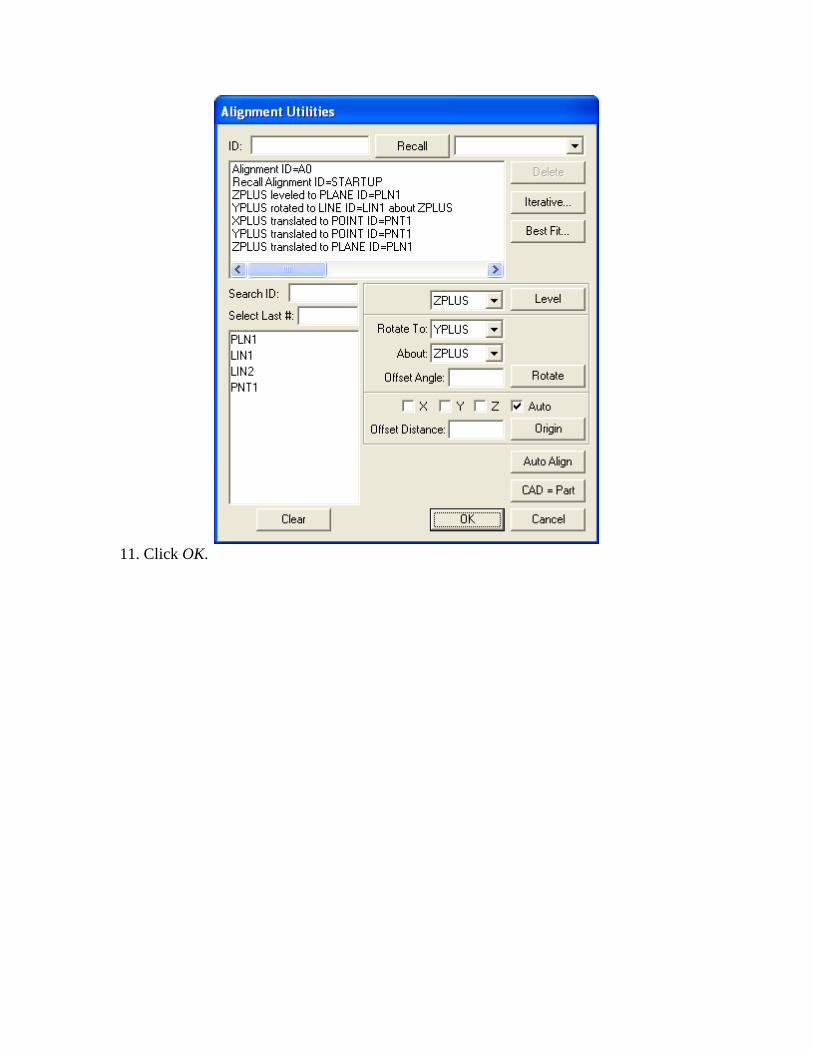
11. Click OK.
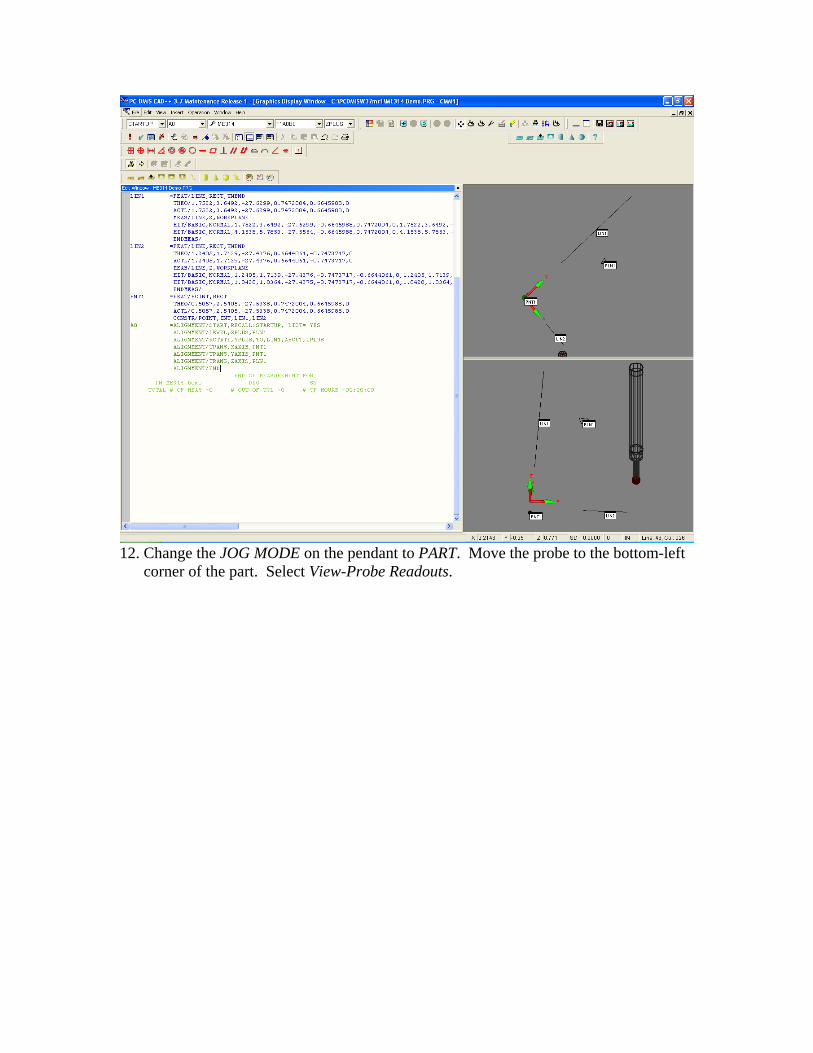
12. Change the JOG MODE on the pendant to PART. Move the probe to the bottom-left
corner of the part. Select View-Probe Readouts.
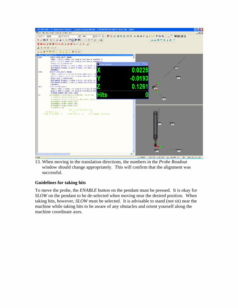
13. When moving in the translation directions, the numbers in the Probe Readout
window should change appropriately. This will confirm that the alignment was successful.
Guidelines for taking hits To move the probe, the ENABLE button on the pendant must be pressed. It is okay for SLOW on the pendant to be de-selected when moving near the desired position. When taking hits, however, SLOW must be selected. It is advisable to stand (not sit) near the machine while taking hits to be aware of any obstacles and orient yourself along the machine coordinate axes.
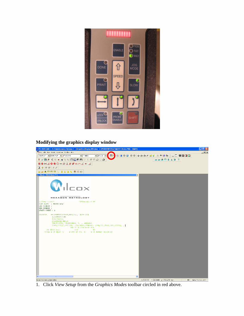
Modifying the graphics display window
1. Click View Setup from the Graphics Modes toolbar circled in red above.
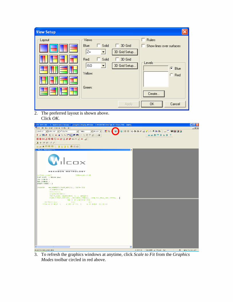
2. The preferred layout is shown above.
Click OK.
3. To refresh the graphics windows at anytime, click Scale to Fit from the Graphics
Modes toolbar circled in red above.
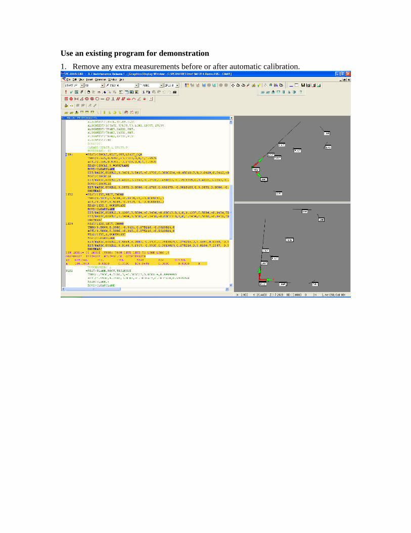
Use an existing program for demonstration 1. Remove any extra measurements before or after automatic calibration.
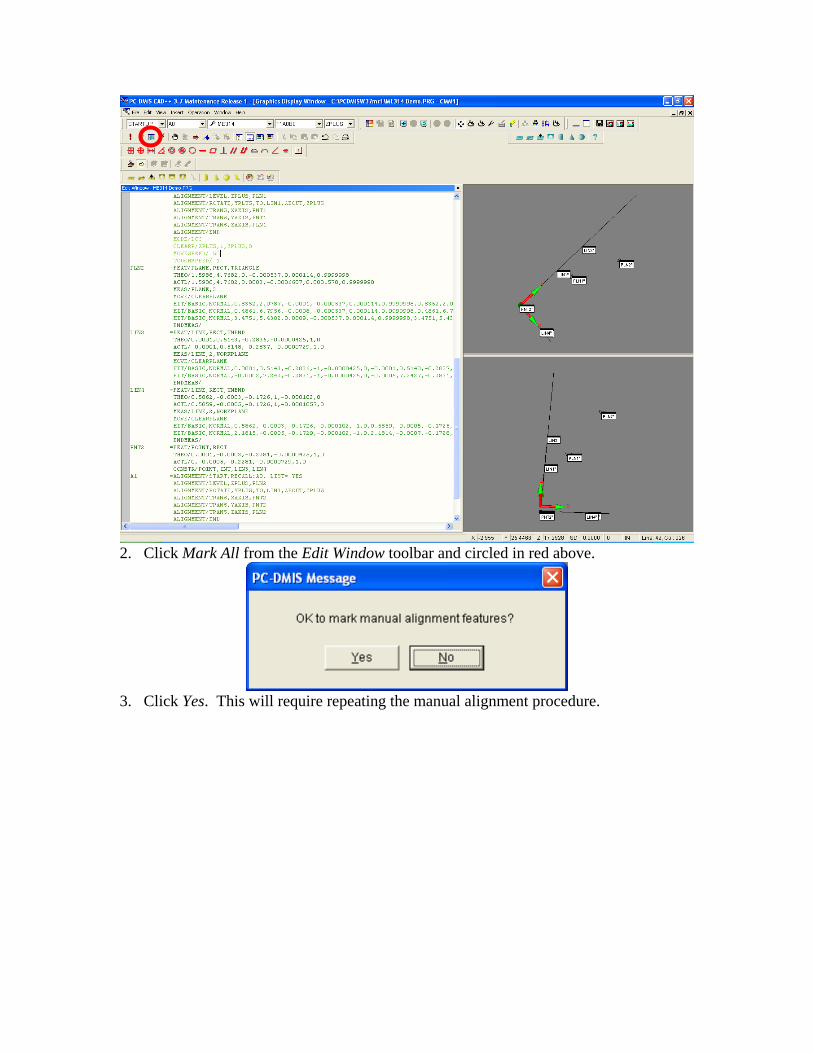
2. Click Mark All from the Edit Window toolbar and circled in red above.
3. Click Yes. This will require repeating the manual alignment procedure.

4. Click Execute on the Edit Window toolbar and circled in red above.Make sure
everything is clear of the tool. While the program is running, pay attention to the behavior of the probe and be ready to hit the E-Stop button on the pendant should something go awry.
5. Click OK.
6. Click OK.
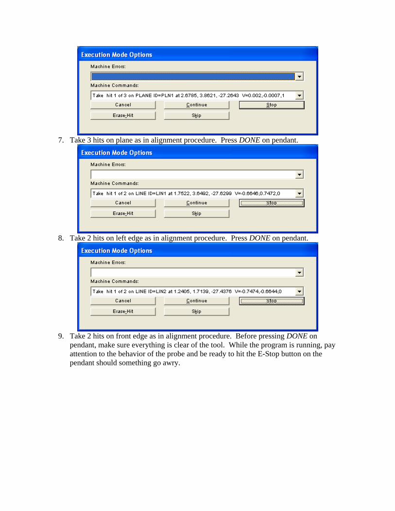
7. Take 3 hits on plane as in alignment procedure. Press DONE on pendant.
8. Take 2 hits on left edge as in alignment procedure. Press DONE on pendant.
9. Take 2 hits on front edge as in alignment procedure. Before pressing DONE on
pendant, make sure everything is clear of the tool. While the program is running, pay attention to the behavior of the probe and be ready to hit the E-Stop button on the pendant should something go awry.
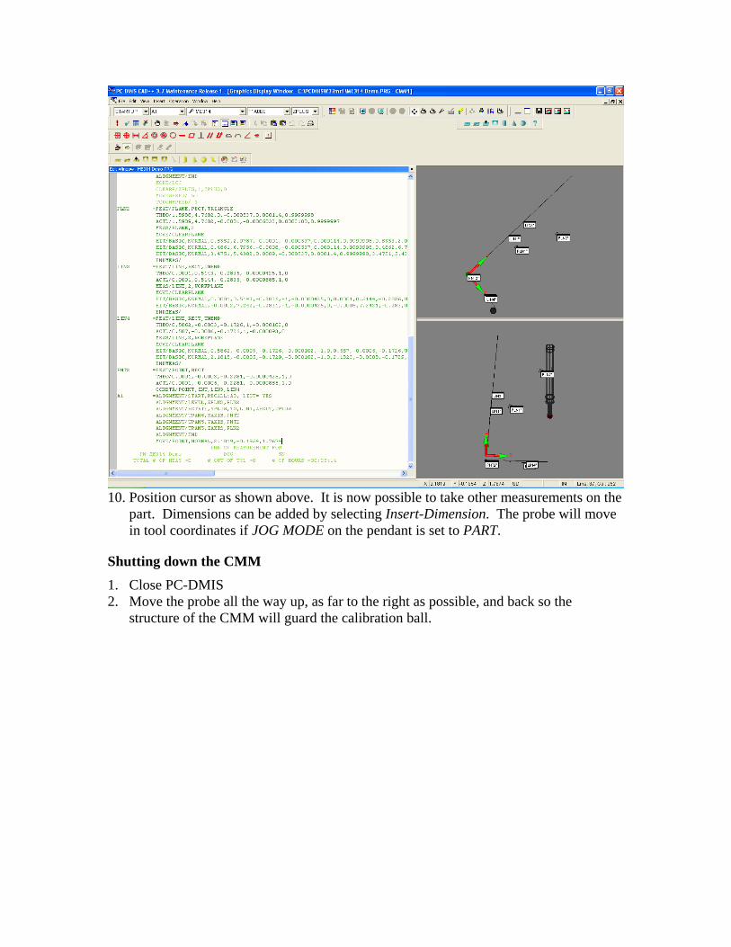
10. Position cursor as shown above. It is now possible to take other measurements on the
part. Dimensions can be added by selecting Insert-Dimension. The probe will move in tool coordinates if JOG MODE on the pendant is set to PART.
Shutting down the CMM 1. Close PC-DMIS 2. Move the probe all the way up, as far to the right as possible, and back so the
structure of the CMM will guard the calibration ball.
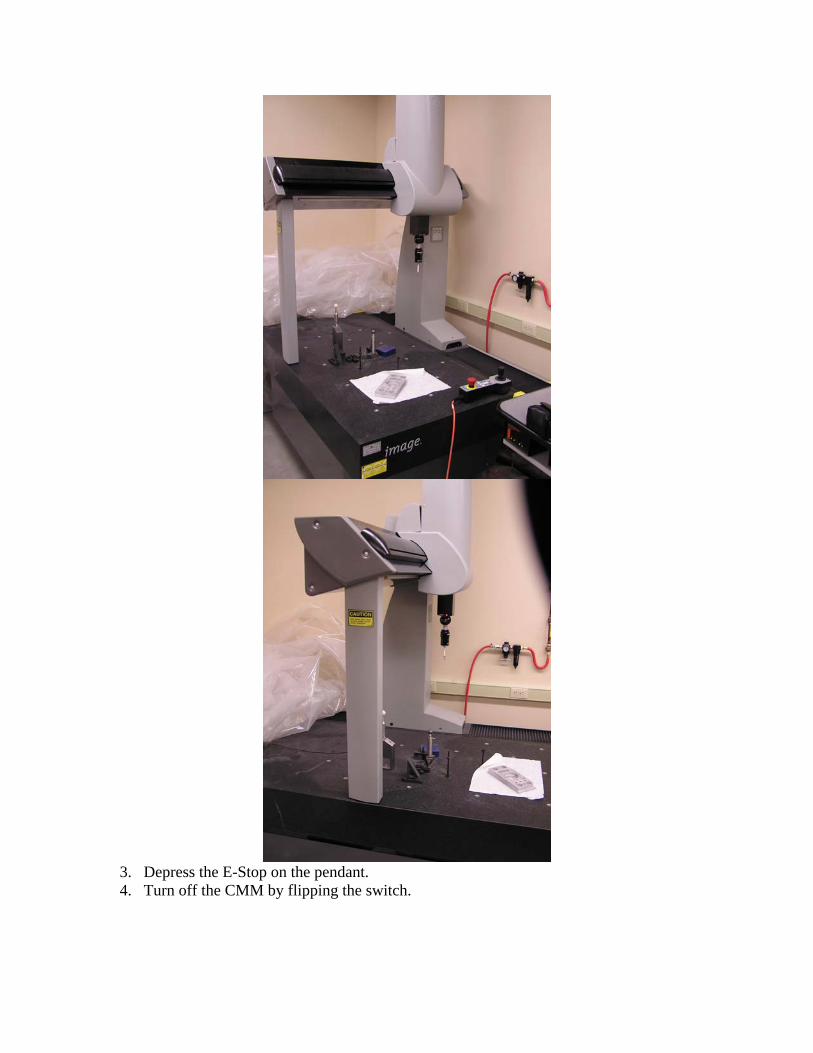
3. Depress the E-Stop on the pendant. 4. Turn off the CMM by flipping the switch.
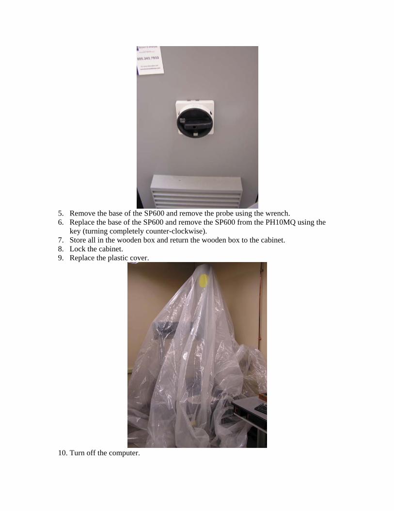
5. Remove the base of the SP600 and remove the probe using the wrench. 6. Replace the base of the SP600 and remove the SP600 from the PH10MQ using the
key (turning completely counter-clockwise). 7. Store all in the wooden box and return the wooden box to the cabinet. 8. Lock the cabinet. 9. Replace the plastic cover.
10. Turn off the computer.