Chapter 13 Fire Ground Hydraulics
63
1 Chapter 13 Fire Ground Hydraulics PURPOSE Pump Operators should develop a working knowledge of the basic theories and formulas of hydraulics. This understanding of basic hydraulics, along with the ability to make practical applications on the fire ground, is the foundation for effective fire stream management at the pump panel. As with all skills, practice will increase one's confidence and ability to deal effectively with even the most difficult fire ground problems. SCOPE Hydraulics is that branch of engineering which deals with the properties of water or other fluids at rest and in motion. The following formulas and materials will apply basic mathematical solutions to achieve field hydraulic calculations. This section does not attempt to offer complete explanations or examples of all hydraulic calculations due to space limitations, but sets forth the basic methods used for Phoenix Fire Department operations. It is recommended that the hydraulic student refer to one of the many hydraulic manuals and textbooks that are available to support these calculations. THE ENGINE PRESSURE FORMULA Engine pressure, also referred to as PDP or pump discharge pressure in most textbooks, is the basis for developing fire stream discharge pressures. Every hose lay the pump operator must pump can have as few a two or as many as all four components to account for in determining the correct engine pressure to pump. Only calculating and pumping the correct engine pressure can assure the pump operator of producing an adequate fire stream at the desired gallon per minute flows. EP = NP + FL + AP + EL Where EP is engine pressure Where NP is nozzle pressure Where FL is friction loss Where AP is appliance value Where EL is elevation The following pages will define the values to be used in determining the correct engine pressure for the hose lay being pumped.
Transcript of Chapter 13 Fire Ground Hydraulics

1
Chapter 13 Fire Ground Hydraulics
PURPOSE Pump Operators should develop a working knowledge of the basic theories and formulas of hydraulics. This understanding of basic hydraulics, along with the ability to make practical applications on the fire ground, is the foundation for effective fire stream management at the pump panel. As with all skills, practice will increase one's confidence and ability to deal effectively with even the most difficult fire ground problems. SCOPE Hydraulics is that branch of engineering which deals with the properties of water or other fluids at rest and in motion. The following formulas and materials will apply basic mathematical solutions to achieve field hydraulic calculations. This section does not attempt to offer complete explanations or examples of all hydraulic calculations due to space limitations, but sets forth the basic methods used for Phoenix Fire Department operations. It is recommended that the hydraulic student refer to one of the many hydraulic manuals and textbooks that are available to support these calculations. THE ENGINE PRESSURE FORMULA Engine pressure, also referred to as PDP or pump discharge pressure in most textbooks, is the basis for developing fire stream discharge pressures. Every hose lay the pump operator must pump can have as few a two or as many as all four components to account for in determining the correct engine pressure to pump. Only calculating and pumping the correct engine pressure can assure the pump operator of producing an adequate fire stream at the desired gallon per minute flows. EP = NP + FL + AP + EL
Where EP is engine pressure Where NP is nozzle pressure Where FL is friction loss Where AP is appliance value Where EL is elevation
The following pages will define the values to be used in determining the correct engine pressure for the hose lay being pumped.

2
FOG NOZZLES There are three basic types of fog nozzles used by the Phoenix Fire Department. They are fixed flow fog nozzles, adjustable flow fog nozzles, and automatic fog nozzles. Depending upon the manufacturer’s specifications each type of nozzle has a desired flow pressure (nozzle pressure). The GPM output of any nozzle is determined by two factors: the size of the discharge orifice and the flow pressure through the discharger orifice. The flow pressure should NOT be change from the manufacturers recommended pressure. Changing the flow pressure will adversely affect the shape, power and reach of the fire stream. This is true of both over pumping the nozzle as well as under pumping the nozzle. In order to change the GPM flow of a nozzle the user must be able to change the size of the discharge orifice while still maintaining the proper flow pressure. Fixed flow fog nozzles are older style nozzles and although they are still being manufactured there is only one place the Phoenix Fire Department we utilize these nozzles and that would be on the high-rise packs. These nozzles are readily identifiable because the GPM flow rate for the nozzle is stamped into the deflector plate of the nozzle. The GPM rating for our fixed flow nozzles is 125 GPM at a flow (nozzle) pressure of 75 PSI. These nozzles are only designed to flow 125 GPM and also produce an effective fire stream. There is no way to adjust the discharge orifice and the nozzle pressure should not be changed. Therefore they should be pumped for 125 GPM each time they are utilized. Adjustable flow fog nozzles are newer in design than fixed flow fog nozzles but have become rare on the Department. These nozzles allow the user the ability to change the discharge orifice by rotating a sleeve on the body of the nozzle to the desired flow. Once selected the pump operator must recalculate and pump the correct engine pressure for the desired GPM flow. These nozzles are currently found on the 2 ½” lines and in some cases the “fog hog” master stream fog nozzle on the deck guns and portable monitors. These nozzles have a designed flow pressure of 100 PSI. The newest and most common nozzles carried on our apparatus are the TFT automatic fog nozzles. This newer technology uses a spring mechanism to control the size of the discharge orifice. As pump pressure is increased the spring causes the orifice to increase in size. As the size is increased the nozzle discharge pressure is maintained at 75 PSI. When the opening is enlarged and the flow pressure remains constant the GPM discharge of the nozzle is increased. The opposite occurs as pump pressure is decreased the size gets smaller and the GPM goes down. These nozzles are found on the 1 ½” hand lines, 1 ¾” hand lines and the 2” hand lines. Automatic fog nozzles are now also widely used on our master stream appliances. Automatic nozzles used on the hand lines are designed to have a nozzle pressure of 75 PSI and have a GPM range of 70 to 200 GPM for the 1 ½” and 1 ¾’ and 70 to 250 GPM for the 2” lines. The automatics on the master streams are operated at 100 PSI nozzle pressure and have a range of 350 to 1000 GPM.

3
All of the fog nozzles with the exception of the adjustable flow nozzles can also be converted to a 1” solid stream nozzle by removing the fog tip from the shut-off of the nozzle. This allows for conversion the appropriate type of nozzle to meets the demands of the firefight. This might be when using CAF, operating in a high rise, basement fires, or when additional reach or penetration is needed.
Nozzle Type Nozzle Pressure
GPM Range
Application
Fixed Flow 75 125 High Rise Fixed Flow Fog Removed 50 200 High Rise
Adjustable Flow 100 120-250 2 ½” Hand Line Adjustable Flow 100 350-1000 Master Streams TFT Automatic 75 70-200 1 ½” and 1 ¾” Hand Lines TFT Automatic 75 70-250 2” Hand Lines
TFT Automatic Tip Removed
50 200 1 ½”, 1 ¾” and 2” Hand Lines
Large Automatic 100 350-1000 Master Streams SOLID STREAM NOZZLES Solid stream or smooth bore nozzles are utilized when greater reach or penetration of the stream is needed or when it is undesirable to generate large volumes of steam such as when fighting fire in a basement, high rise or any other area where rapid ventilation of hot gasses and steam is difficult or impossible. These nozzles are also the desired type of nozzle to use when applying water to a large free-burning defensive fire. These nozzles produce streams that expose a smaller surface area of the water to the heat thus reducing steam generation and allowing more of the water to reach the seat of the fire. When utilized on hand lines these nozzles can be attached to the 2 ½” and 2” hand lines. The Two smaller tips can also be used on the 1 ¾” hand line. It is not recommended that they be used on 1 ½” lines due to the large amount of friction loss in the line and therefore very high engine pressures. When used on hand lines these nozzles have a nozzle pressure of 50 PSI. Changing the tip size determines the volume of water. There are three tips the Department uses on hand lines. They are a 1” tip (200 GPM), a 1 1/8” tip (250 GPM), and a 1 ¼” tip (300 GPM). The 1 ¼” tip is the largest that should ever be placed on a hand line.
Tip Size Nozzle Pressure GPM Flow Application 1 inch 50 200 1 3/4”, 2” and, 2 ½” hand lines
1 1/8 inch 50 250 1 3/4”, 2” and, 2 ½” hand lines 1 ¼ inch 50 300 2” and, 2 ½” hand lines
The most common place the Department uses solid stream nozzles is on master stream devices such as deck guns, portable monitors and ladder pipes. These nozzles should be used whenever we are attacking large free-burning high thermal fires or in other words defensive operations. The tips for the master stream appliances come in four sizes and are all part of a “stack tip”

4
configuration. The four tip sizes are 1 3/8” (500 GPM), 1 ½” (600 GPM), 1 ¾” (800 GPM), and 2” (1000 GPM). They all require 80 PSI of nozzle pressure to produce effective streams.
Tip Size Nozzle Pressure GPM Flow Application 1 3/8 inch 80 500 Defensive Master Streams 1 ½ inch 80 600 Defensive Master Streams 1 ¾ inch 80 800 Defensive Master Streams 2 inch 80 1000 Defensive Master Streams
All solid stream nozzles being used on master stream appliances also require a stream shaper to be placed between the nozzle and the appliance. As water travels through hose and piping it travels not in a linear fashion but rotates the effect can be seen each time you flush a toilet. While this rotation is a contributing factor to friction loss through the piping or hose is only becomes an issue when the water is to be discharged through a nozzle. If the stream shaper is not in place to stop the rotation of the water as it exits the nozzle the centrifugal force created will break the stream apart. This significantly affects the reach, shape, and penetration of the stream. Most of the stream shapers used by the PFD serve two purposes; they stop the rotation of the water thus shaping an effective stream and they also adapt the threads from NST to Phoenix thread. SPECIALTY NOZZLES There are two specialty nozzles being used by the Department. Penetrating or piercing nozzles are carried on all apparatus. Engine companies carry 6’ nozzles and the ladder companies carry 3’ nozzles. These nozzles are useful in fighting fire in confined or enclosed spaces like false mansards and in the framing around a zero-clearance fire place. These nozzles attach to 1 ½”, 1 ¾” and 2” hose and flow 95 GPM and have a nozzle pressure of 100 PSI. The second specialty nozzle carried on some of the ladder trucks is the cellar nozzle also called a basement nozzle or a Bresnan distributor. These nozzles were designed to fight fires in basements and are used by cutting a hole in the floor above the fire a dropping the nozzle into the hole. These nozzles attach to 2 ½” hose and flow 250 GPM and have a nozzle pressure of 100 PSI. Nozzle Type Nozzle Pressure GPM Flow Application Penetrating 100 95 Concealed Spaces
Cellar 100 250 Basements FRICTION LOSS FOR HANDLINES Of the four components that can comprise the engine pressure friction loss is the most difficult of the four to deal with. This is because it is the only component that requires a calculation to be performed. There are three major factors that influence friction loss: How much water? (GPM), What size hose? (diameter), How far? (length of hose). These are the pieces of information the pump operator must know in order to calculate the friction loss in the hose.

5
Friction loss occurs any time water flows through hose, couplings, appliances, pipes, plumbing and adaptors. For the purposes of calculating the engine pressure the FL (friction loss) component of the formula deals with the hose and couplings only. The pressure lost due to friction in appliances, plumbing, and piping will be accounted for under the appliance portion of this chapter. When the other two factors remain constant, friction loss is increased when the volume of water is increased through the hose line. Again with the other two factors remaining constant, friction loss is increased when using smaller diameter hose and the longer the hose lay the greater the friction loss when the diameter and volume remain constant. When calculating friction loss in hand lines utilize the following formula:
GPM x HS
10 - 10 = FL / 100 feet of hose
HS = 8 for 1” hose 4 for 1 ½" hose
3 for 1 3/4" hose 2 for 2" hose 1 for 2 ½" hose
Example; 150 GPM through 100 feet of 1 3/4" line
150 x 3 10 - 10
450 10 - 10 45 - 10
35 PSI fl in 100 feet of hose
Example; 200 GPM through 100 feet of 2" line
200 x 2 10 - 10 400 10 - 10 40 - 10
30 PSI fl in 100 feet of hose

6
Based upon the information to this point the pump operator can now calculate engine pressures for simple hand lines. When dealing with simple hand lines there are two components of the friction loss formula to account for, the nozzle pressure and the friction loss in the hose. Using the information in the previous pages we will look at calculating the correct engine pressures for the following four hose lays.

7
ELEVATION The next component of the friction loss formula to cover is elevation. Any time there is a difference in elevation between the pump and the nozzle or wherever the water is being delivered we must adjust the engine pressure to account for that difference. Water, having weight, exerts a certain amount of pressure at the bottom of any container or in this case hose. The combined effect of gravity and the weight of the water is what create this pressure. There are two types of pressure that are dealt with here. The first is called head pressure; head pressure is the amount of pressure that is produced when water moves downhill from the source (the pump) to the end discharge (the nozzle). The second is called back pressure; back pressure is the amount of pressure coming back at the source (the pump) as water is being pumped uphill to the end discharge (the nozzle). The actual physics involved in the two types of pressure is exactly the same. The only difference between the two is where the pump is in relation to the nozzle.
8
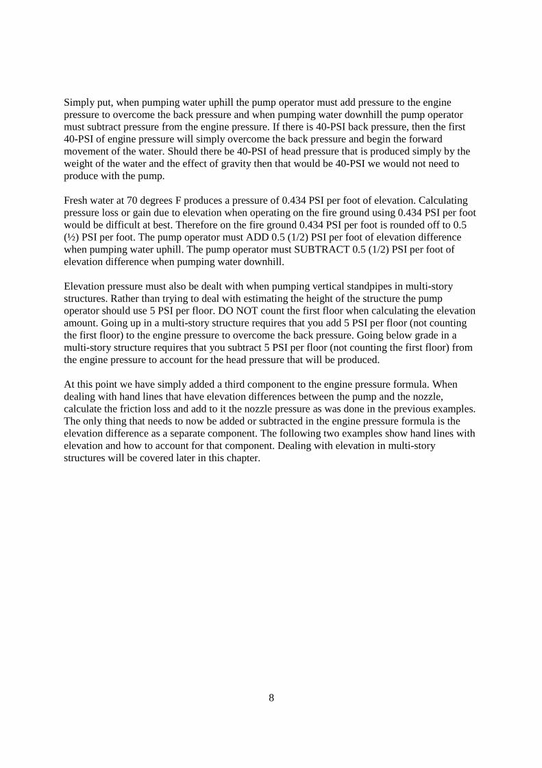
Simply put, when pumping water uphill the pump operator must add pressure to the engine pressure to overcome the back pressure and when pumping water downhill the pump operator must subtract pressure from the engine pressure. If there is 40-PSI back pressure, then the first 40-PSI of engine pressure will simply overcome the back pressure and begin the forward movement of the water. Should there be 40-PSI of head pressure that is produced simply by the weight of the water and the effect of gravity then that would be 40-PSI we would not need to produce with the pump. Fresh water at 70 degrees F produces a pressure of 0.434 PSI per foot of elevation. Calculating pressure loss or gain due to elevation when operating on the fire ground using 0.434 PSI per foot would be difficult at best. Therefore on the fire ground 0.434 PSI per foot is rounded off to 0.5 (½) PSI per foot. The pump operator must ADD 0.5 (1/2) PSI per foot of elevation difference when pumping water uphill. The pump operator must SUBTRACT 0.5 (1/2) PSI per foot of elevation difference when pumping water downhill. Elevation pressure must also be dealt with when pumping vertical standpipes in multi-story structures. Rather than trying to deal with estimating the height of the structure the pump operator should use 5 PSI per floor. DO NOT count the first floor when calculating the elevation amount. Going up in a multi-story structure requires that you add 5 PSI per floor (not counting the first floor) to the engine pressure to overcome the back pressure. Going below grade in a multi-story structure requires that you subtract 5 PSI per floor (not counting the first floor) from the engine pressure to account for the head pressure that will be produced. At this point we have simply added a third component to the engine pressure formula. When dealing with hand lines that have elevation differences between the pump and the nozzle, calculate the friction loss and add to it the nozzle pressure as was done in the previous examples. The only thing that needs to now be added or subtracted in the engine pressure formula is the elevation difference as a separate component. The following two examples show hand lines with elevation and how to account for that component. Dealing with elevation in multi-story structures will be covered later in this chapter.

9
HANDLINE APPLIANCES Some hand line set-ups require the use of an appliance. The two most common scenarios in which we would utilize an appliance are the horizontal standpipe (gated wye) and a standpipe system in a structure. Earlier in the chapter friction loss was described as pressure that is lost any time water flows through hose, couplings, adaptors, appliances, plumbing, etc. Appliance values are a representation of that friction loss that occurs in the plumbing that makes up the particular appliance. When accounting for hand line appliances the assigned values are only given at flows at or above 350 GPM through the appliance. Flows of less than 350 GPM cause the appliance value to become zero. The appliance values for these two hand line appliances are:
Gated wye = 10 PSI Standpipe = 20 PSI (this would include the gated wye attached to the standpipe)
Like we did with the addition of elevation as a component, the appliance value should be added to the engine pressure formula as a separate component.

10
PUMPING HORIZONTAL STANDPIPES (GATED WYE) When setting up and pumping a horizontal standpipe there are two items of note that the pump operator and the firefighters must be aware of. First the two lines coming off of the wye must be alike hydraulically. This means that from the gated wye out if you were to calculate each line separately each must require approximately the same pressure. Using two lines that are not hydraulically alike would require that one of the lines be gated down at the wye. Although they are manufactured and available, the Department does not carry wyes with discharge gauges on the wye. So although you can “gate down” one of the discharges off of the wye you cannot gate it down accurately without having a gauge on the wye. The second issue to be aware of is that when shutting down one of the two nozzles working off of the wye, there will be an increase in pressure and volume to the second line that is still operating. This can create a hazard for the firefighters operating that line should they be unable to handle the increase in volume from their nozzle. This fact requires the firefighters working off of a wye to exaggerate how slowly they close the nozzle on their line. Closing the nozzle slowly will allow the other firefighters to make whatever adjustments they need when they sense the increase in volume from the nozzle. Utilize the following steps when calculating the engine pressure for a horizontal standpipe: Add to the engine pressure formula the nozzle pressure for ONE nozzle Add to the engine pressure formula the friction loss for ONE of the hand lines Combine the volumes of the two nozzles Using the combined volume, decide if the wye will get its appliance value and add that value to the engine pressure formula Using the combined volume, calculate the friction loss in the 2 ½ inch hose and add to the engine pressure formula under friction loss Note; there should be two friction loss entries Add or subtract any elevation difference between the pump and the nozzle

11
PUMPING STANDPIPES The same basic rules that apply to the horizontal standpipes apply to standpipes in structures. The two lines should be alike hydraulically and the nozzles should be closed slowly to decrease the chances of a firefighter being injured. Should there be more than one set of lines from the standpipe, calculate and pump for the highest required pressure. This would typically be the lines operating on the highest floor number. Utilize the following steps when calculating the engine pressure for a standpipe: Add to the engine pressure formula the nozzle pressure for ONE nozzle Add to the engine pressure formula the friction loss for ONE of the hand lines Combine the volumes of the two nozzles Using the combined volume, decide if the standpipe will get its appliance value and add that value to the engine pressure formula Typically there should be two lines from the apparatus to the inlets of the standpipe system Calculate the friction loss in one 2 ½ inch hose at ½ the total volume being pumped and add to the engine pressure formula under friction loss Note; there should be two friction loss entries Add or subtract any elevation difference between the pump and the nozzle at 5 PSI per floor excluding the first floor

12
FRICTION LOSS FOR MASTER STREAMS AND SUPPLY LINES When dealing with master streams and pumping supply lines all of the components of the engine pressure formula are still used. The nozzle pressures when pumping through master streams are 100 PSI for a fog nozzle and 80 PSI for a solid stream nozzle and elevation is still 0.5 PSI per foot. Upcoming in the following sections there will be a different calculation to be used for friction loss in hose of three inches in diameter and larger as well as the amount of pressure to include for the various appliances used with master streams. When calculating friction loss in larger diameter hose lines the following formula should be used.
Q x (Q - 1) HS = FL / 100 feet of hose GPM HS = 1 for 3" hose Q = 100 2 for 3 ½" hose
4 for 4" hose 12 for 5" hose

13
Example; 500 GPM through 100 feet of 3 ½" hose
500 100 = 5 Q = 5
5 x (5-1) 2
5 x 4
2
20 2
10 PSI fl in 100 feet of hose Example; 800 GPM through 100 feet of 4" hose
800 100 = 8 Q = 8
8 x (8-1) 4
8 x 7 4
56
4
14 PSI fl in 100 feet of hose
MASTER STREAM APPLIANCES Every master stream or supply line to be pumped will have an appliance associated with the hose lay. Master stream appliances used by the Phoenix Fire Department include; deck guns (commonly called “Stang guns”), portable monitors, and ladder pipes. An appliance value is also given to a relay pump or a forward pump when pumping supply lines. The appliance values given are specific to the equipment used by the Department. Appliance values vary even for the same type of appliance depending upon the age, size, internal plumbing, design, and the manufacturer of the appliance.

14
The appliance value assigned to a particular device is a reflection of the friction loss that occurs when pumping water through the piping and plumbing that make up the appliance. The appliance value given is typically based on 800 GPM. The amount of pressure to be added to the engine pressure formula should get the pump operator close to the desired engine pressure. The reason it may only get you close is that it will depend upon the actual volume of water flowing through the device. Since the value given is actually friction loss and remembering that one of the major factors that will influence how much friction loss occurs is the volume of water flowing. Therefore if the operator is flowing less than 800 GPM the appliance value may be slightly less than the assigned value. The inverse is also true in that volume of greater than 800 GPM will cause the actual appliance value to be greater. What is the bottom line? Calculate the engine pressure, flow the stream and then look at the stream for its effectiveness. If the stream looks weak, lacks power and reach and the flow is greater than 800 GPM it will be necessary to increase the engine pressure 5, 10, or 15 PSI until an effective stream is obtained. Over pumping a stream with too high a pressure can also cause a poor stream. If the stream is breaking up into a spray and has poor reach and the flow is greater than 800 GPM it will be necessary to decrease the engine pressure 5, 10 or 15 PSI until an effective stream is obtained. The following is a list of the appliance values for Phoenix Fire Department equipment. Deck guns are pre-plumbed top (deck) mounted master stream devices capable of up to 1000 GPM. Salisbury engines 15 PSI appliance value ALF engines 15 PSI appliance value Pierce engines 15 PSI appliance value Portable monitors are deployed on the fire ground by removing the head of the deck gun and placing it onto a portable base. Monitors are capable of up to 1000 GPM and are 15 PSI for the appliance value There is a much broader spectrum in the appliance values for the various ladder trucks on the Department. The ladder pipes on the reserve ladders have a maximum volume of up to 1000 GPM. These pipes only have one nozzle assembly thus the 1000 GPM limitation. The ALFs, Pierces and the Bronto (L9) have a maximum GPM flow of 2000 GPM due to the fact that they are platform style ladders and have two guns on the platform from which to flow water. Each gun is capable of 1000 GPM. Reserve ladders have 70 PSI appliance values ALF platform ladders have 50 PSI appliance values The Bronto (L9) has a 50 PSI appliance value The Pierce ladders have an appliance value of 50 PSI

15
The last of the appliance values is used when pumping water to a forward pump or to a relay pump. Unlike the previously listed appliance values the 20 PSI given in this hose lay does not represent pressure that is lost due to friction as the water travels through the appliance. The 20 PSI is actually extra pressure given to maintain a net pump pressure for the next pump of 150 PSI or less or a minimum intake pressure at the forward pump or the relay pump of at least 20 PSI to avoid having the pump cavitate. The forward pump may require a residual pressure of greater than 20 PSI based upon the volume of water they are attempting to flow and the pump discharge pressure of the forward pump. As is outlined in the next chapter on Pumping, maximum discharge volume from a centrifugal pump occurs at 150 PSI net pump pressure. Net pump pressures of greater than 150 PSI reduce the volume of water that can be discharged from the pump. The calculation for pumping to a forward or relay pump is their pump discharge pressure minus 150 or 20 PSI whichever is greater. Appliance Value in PSI Deck Gun Salisbury, ALF or Pierce 15 PSI Portable Monitor 15 PSI Reserve Ladders 70 PSI Pierce Ladders 50 PSI ALF Platforms 50 PSI Bronto 50 PSI Forward or Relay Pumps Minimum 20 PSI or the other pumps PDP – 150
whichever is greater CALCULATING SINGLE LINE MASTER STREAMS AND SUPPLY LINES Deck Guns - Calculating the engine pressure for a deck gun is the easiest of all of the various hose lays. When calculating any hose lay, add together only those things that are on the discharge side of the pump. For a deck gun, add together the nozzle pressure and the appliance value to determine the engine pressure. This means that there are only two engine pressures when pumping a deck gun on the Phoenix Fire Department; 95 PSI with a smooth bore nozzle and 115 PSI with a fog nozzle.

16
Portable monitors – When calculating the engine pressure for portable monitors add together the nozzle pressure, friction loss, appliance value and any elevation difference between the pump and the nozzle to determine the engine pressure.

17
Ladder pipes – When calculating the engine pressure for ladder pipes as the forward pump operator add together the nozzle pressure, friction loss, appliance value and the elevation of the ladder pipe to determine the engine pressure. Forward pumps and relay pumps – When calculating the engine pressure for pumping a supply line to a forward pump or to a relay pump add their PDP – 150 or 20 PSI (whichever is greater) plus the friction loss in the hose and add or subtract any elevation difference between the two pumps. When pumping through hose on the fire ground there is a maximum pressure that can be pumped on the lines depending upon the type of hose. Most of the hose used by the Phoenix Fire Department has cloth jacket(s) surrounding the rubber liner of the hose. When pumping through this type of hose the maximum pressure on the fire ground is 250 PSI. This provides a failure safety margin of 50 PSI below the annual test pressure. The Department also uses a green 2 ½” line in the high-rise areas. This green 2 ½” hose can be pumped on the fire ground safely as high as 500 PSI. Many of the departments in the Phoenix Metropolitan area use supply line that does not have a cloth jacket. This yellow four or five inch “rubber” hose has an annual test pressure of only 200 PSI. On the fire ground this type hose should NOT be pumped higher that 180 PSI for any

18
reason. This type of hose tends to fail when the hose pulls out of the coupling. This can create a flailing hose with a very heavy coupling on it that can severely injure anyone it makes contact with. The Phoenix Fire Department has 5000 feet of this type of 5” hose on the Hose truck. CALCULATING MULTIPLE LINE MASTER STREAMS AND SUPPLY LINES When utilizing two lines to provide water to a forward pump, relay pump or to a ladder pipe there will be an extra initial step the pump operator must take in order to calculate the friction loss in the hose. The step requires the splitting of the flow through the two lines. When both lines being pumped to the same location are the same diameter and approximately the same length then the pump operator should split the flow evenly between the two lines and then calculate the friction loss in ONE of the lines at ONE-HALF the total GPM flow. Note: Any time we are supplying water to a platform type ladder pipe (2 guns) we MUST lay two supply lines and have them pumped in order to flow any where near the ladder’s GPM capability. At times, especially when we have reversed a second supply line from the forward pump to the hydrant, the length of the lines will not be the same. When this happens the pump operator should use the average length of the two lines when multiplying the per 100 foot friction loss value by the length of the hose. On the fire ground the pump operator may opt to use the average length of the two lines or the length of the longer of the two in order to make the math easier. For example if the first line is 550 feet and the second is 650 feet then the average length is 600 feet and the pump operator would multiply the per 100 foot value by six. If on the other hand the first line was 750 feet and the second line was 800 feet then the pump operator should use eight when multiplying for the length of the hose lay (the longer of the two lines) rather than having to multiply by 7.75 (the average length of the two lines). CALCULATING “IN-BETWEEN” FLOWS At times the pump operator may encounter hose lays where the flow is something other than 500, 600, 700, GPM, etc. These are what are known as “in-between” flows. In-between flows are flows such as 350, 450, 550 GPM etc. In-between flows will cause “Q” to be something other than a whole number and will cause difficulty when trying to calculate friction loss especially in the pump operator’s head. A simple adjustment should be made in the friction loss calculation in order fro the pump operator to come back to dealing with whole numbers again.

19
Follow these steps to adjust for these in-between flows:
Find Q Apply Q to the formula Apply Q x (Q-1) Now take the larger of the two numbers and round it down to the whole number. Take the smaller number and round it up to the whole number Continue as before to determine the friction loss in the hose
Example for “in-between” flow - 850 GPM through 100 feet of 4" hose
850 100 = 8.5 Q = 8.5
8.5 x (8.5 –1) 4 8.5 x 7.5 4
8 x 8 4
64 4
16 PSI FL in 100 feet of hose

1
Pumping Operations Chapter 14
BASIC PUMP THEORY All modern fire apparatus use centrifugal pumps as their main fire pump. Centrifugal pumps have some limitations but the benefits of use this type of pump far outweigh those limitations. Some of the benefits to using a centrifugal pump as compared to positive displacement pumps are: The ability to use all of the pressure entering the intake side of the pump. The ability to stop the flow of the water without stalling the pump and the engine. The ability to produce a smooth continuous stream. The centrifugal pump consists of two basic components: the impeller and the pump casing. The impeller turns on a shaft driver by a PTO, direct gear drive, or a drive shaft from a power transfer case. Water enters the eye (center) of the impeller and is thrown outward to the edge of the impeller by the centrifugal force created by the rotation of the impeller on the shaft. The water is then discharged into an area of the pump casing called the volute and then out of the discharge of the casing into the pump discharge manifold where it is distributed to the various discharges on the apparatus. Centrifugal pumps can do one of two things; they can produce pressure or they can produce volume. However they cannot produce both at the same time. Centrifugal pumps are rated for their ability to produce certain volumes at set net pump pressures. The net pump pressure is the discharge pressure minus the intake pressure (PDP – Intake PSI + Net Pump Pressure). When these pumps are rated and then annually tested the evaluation process is done at draft with ten feet of lift. (Lift is the distance in height from the center of the intake to the top of the static water source.) Pumps must be capable of discharging their rated maximum capacity at 150 PSI net pump pressure. As net pump pressure increases the volume of water the pump is capable of discharging decreases even to the point that at 250 PSI net pump pressure the pump can only discharge 50% of its maximum rated capacity. The following chart demonstrates this phenomenon: Pump Size Net Pump Pressure GPM Flow % of Rated Capacity 1250 GPM 150 PSI 1250 GPM 100% 1250 GPM 200 PSI 875 GPM 70% 1250 GPM 250 PSI 625 GPM 50%
1500 GPM 150 PSI 1500 GPM 100% 1500 GPM 200 PSI 1050 GPM 70% 1500 GPM 250 PSI 750 GPM 50%

2
Most pump operators believe that increasing the pump discharge pressure or engine pressure will increase the GPM being discharged from the pump. While this is true it is only true to a certain point, that being 150 PSI net pump pressure. Once the net pump pressure rises above 150 PSI the volume of water will decrease as pump pressure is increased. Where this becomes important for the pump operator is when they are pumping master streams and supply lines. Remembering that a centrifugal pump will use all of the volume and pressure entering the pump as well as being able to increase the discharge pressure above that of the incoming pressure it should also be noted that a 1250 GPM pump is capable of discharging greater than 2000 GPM when supplied from a pressurized source such as a hydrant with a key pump delivering the water to them from the hydrant. When the pump operator is, for example, pumping a ladder pipe and desires to flow 1200 - 2000 GPM this can be accomplished by using two supply lines from the key pump to the forward pump and adjusting the net pump pressures on both pumps so that they are at or below 150 PSI. Should the necessary PDP for the forward pump be 200 PSI then the intake pressure at the forward pump must be increased by the key pump to a minimum of 50 PSI. The key pump operator is typically told in hydraulics classes to provide a minimum of 20 PSI to the forward pump in addition to the calculated friction loss and any elevation differences to prevent cavitation of the forward pump. Contact the key pump operator and have them increase the 20 PSI minimum to the amount necessary to maintain a net pump pressure of 150 PSI or less. As the key pump operator having an understanding of this principle of pump physics should assist you in knowing how to adjust to provide the forward pump with the residual pressure they require on their intake. The same physical limitations of the centrifugal pump apply when pumping supply lines. Reducing the friction loss and thus reducing the PDP and the net pump pressure is the primary reason to lay a second supply line to the forward pump and is critical to the success of the operation. Further information on the components and theory of centrifugal pumps is available from a number of textbooks as well as time spent taking an apparatus class at the local community college. UNDERSTANDING THE PUMP PANEL Understanding the function of the pump panel components actually begins in the cab of the apparatus. Placing apparatus into pump gear is dependent upon the pump drive arrangement. There are two basic types of drive arrangements that are, or have been, used by the PFD. Full torque PTO arrangements and slit-shaft gear case (transfer case) arrangements. The Salisbury and ALF engines use a full torque PTO system and are placed into pump very differently than the E-One and the Pierce engines. Placing the Salisbury and ALF engines into pump requires placing the transmission into neutral and then shifting the PTO switch to the pump position. The transmission remains in neutral with these trucks as the power to turn the pump comes from a power take-off system and not through the transmission. Placing the transmission into drive with these trucks will in fact place the truck into road gear and the

3
electronic pressure governor on the pump panel with not function and not allow the truck to pump water. The E-One and Pierce apparatus use a very different system to engage the pump. This transfer case system is similar in nature to the transfer case to a four-wheel drive vehicle except that the transfer case will sent power to the drive wheels OR the pump but not both at the same time. This apparatus is placed into pump by placing the transmission into neutral, shifting the pump shift to the pump position, and then placing the transmission back into drive. Engaging the transmission connects the motor to the transfer case in this type of arrangement. Although a pump panel can look very different from others based upon the age, installed systems, and the manufacturer the same basic components are present on all pump panels. It’s a matter of where they are located, what they look like, and how they are labeled. The displayed pump panel is that of an ALF. The pump operator must become familiar with the pump panel on the type of apparatus that they are driving that shift in order to be proficient at its operation.

4
Main Engine and Pump Controls (The Grey Section)
#1 – Main Intake Pressure Gauge
This gauge reads the pressure on the intake side of the pump and must be capable of reading negative pressure for drafting operations. This gauge is also referred to on many panels as the “compound” gauge.
#2 – Main Discharge Pressure Gauge
This gauge reads the pressure inside of the discharge manifold on the pump. The reading on this gauge is typically higher the pressure on the individual discharge pressure gauges. Individual discharge pressure gauges should be used in determining the proper PDP for the individual lines.
#3 – Test Gauge Connections These connections are used to certify and test the pump. On the PFD this is used by he
mechanics for the annual pump test. #4 – Pump Engaged Indicator Light

5
This light must be illuminated in order to operate the pump. The light comes on when the apparatus is placed into pump gear properly. Do not try to increase the throttle unless this light is illuminated.
#5 – Governor Enable Switch This switch changes the pump control from the cab to the pump panel. In the event the
pump operator begins the pumping process from the cab and for some reason the situation escalates and additional lines need to be deployed this switch will engage the PSG on the pump panel. It should be noted that the engine RPM will decrease to idle and the pump operator will need to increase the pump pressure again to the desired pressure.
#6 - Motor Information Center
This device displays the status of the motor or engine functions on the apparatus. Engine RPM, oil pressure, water temperature, and voltage are the most common displays available thereby replacing the need for those gauges on the pump panel as was done in years past. Some of these information centers also display other issues in the form of warning lights and buzzers when there is a problem with the apparatus in much the same fashion as the warning lights on the dashboard.
#7 - Electronic Governors
Also call pressure sensing governors (PSG) and pressure control governors (PCG), this device is the throttle control for the engine as well as the discharge pressure control device for the pump. Most apparatus with PSG do not have discharge pressure relief valves although the PFD has had some trucks in the past that had both systems (E-One Hush with transverse pump panels). Electronic governors typically have 3-5 buttons or switches used to operate them. The “Mode” button places the PSG into one of two modes, pressure (PSI) or throttle (RPM). The apparatus should never be operated in the throttle (RPM) mode on the fire ground except when establishing a prime when drafting. When the PSG is operated in the throttle (RPM) mode there is NO automatic control of the discharge pressure and the system will NOT protect the firefighters from excess pressure. Other than the short term exception listed above, the PSG should always be operated in the pressure (PSI) mode. The up and down arrows when pushed will increase or decrease the engine pressure and if the PSG is in the pressure (PSI) mode the truck will automatically throttle up and down to maintain the discharge pressure for which it is set. The “Idle” button is used to bring the engine back to idle and turns the PSG off or out of either the PSI or RPM modes. It is not necessary to idle down with the up and down arrows when shutting down pump operations. The “Preset” button, when programmed, will throttle the truck up to a preset point. Typically this is 100 PSI on trucks with CAF systems. Use of this button is optional and it should be noted that using this button brings the engine up to that point and if more or

6
less pressure is desired the up and down arrows can be used to make the final adjustments to the PDP.
#8 – Pump Overheat Light
This light illuminates if the internal pump temperature becomes excessive. This is usually caused by failure to flow water through the pump for too long a period of time. If the light comes on open a discharge or the tank fill valve and move water through the pump to cool it down. Do not take the truck out of pump gear until the pump has been cooled.
#9 – Auxiliary Cooler
This valves moves pump water through a heat exchanger that assists in removing heat from the apparatus motor’s coolant. Generally speaking here in the valley most companies leave this valve open all of the time. The valve should be closed however when trying to pull a prime when drafting. The valve can be reopened after getting a prime.
#10 – Panel Light Switch This switch turns on and off the panel lights for low light operations. #11 – Primer Valve
This valve turns on the priming pump when attempting to get a prime when beginning drafting operations. Many older priming pumps use oil or anti-freeze as a lubricant and to prevent rust in the priming pump. These type apparatus should have the priming pump activated for about 5 seconds during the morning pump check to see if the pump is operational and to help reduce corrosion in the pump. These priming systems will also have a reservoir for the oil or anti-freeze that must be checked and topped off periodically. Newer primers use oil-less systems and don’t require oil or anti-freeze for lubrication and corrosion protection.
#12 – Pump Speed Counter This port is used for testing, repair and maintenance by the mechanics.

7
Water Supply Controls (Blue Section)
#1 – Tank to Pump Valve
This electric valve, when opened, allows water to move from the water tank into the intake side of the pump. There is a clapper valve at the bottom to prevent water from flowing backwards into the tank when changing over to hydrant water. The valve should be fully opened when operating on tank water. The valve can be left open or can be closed when the change over from tank water to hydrant water is complete providing the clapper valve is working properly. The valve should be closed when attempting to prime the pump at a drafting site.
#2 – Water Tank Level This gauge shows the level of water in the water tank. #3 – Tank Fill Valve
This valve allows water to move from the discharge side of the pump up into the water tank. The valve should be opened to fill the tank. The valve should be opened partially after the change over to hydrant water in order to begin refilling the tank in case there is a loss of supply line. The valve can also be used to move water through the pump when no other water is flowing in order to help keep the pump from over heating.
#4 – Front 4” Intake Valve
This valve opens the front intake or suction to allow water into the intake side of the pump from an external pressurized source.

8
#5 – Rear Main 6” Intake Valve This valve opens the large rear main intake or suction to allow water into the intake side of the pump from an external pressurized source. This should be the connection point for the first supply line into the apparatus.
#6 – Rear Main Intake Air Bleed
This valve removes the air from the supply line and should be opened prior to opening the intake valve. Once ALL of the air is removed from the supply line turn off this valve and open the intake valve. Failure to bleed the air from the supply line will force air into the pump and through the hand lines being used by the firefighters possibly causing injury or death. All intakes have air bleed valves have bleeder valves that should be used prior to opening the respective intake.
#7 – Rear Auxiliary 4” Intake
This valve opens the 4” rear intake or suction to allow water into the intake side of the pump from an external pressurized source.
#1 – Discharge Valve for #1 Discharge
This valve opens the #1 discharge to flow water from the LDH discharge on the left rear of the apparatus.

9
#2 – Left Hosebed Discharge Valve This valve opens the 2 ½” discharge to flow water from the 2 ½” discharge on the left rear of the apparatus.
#3 - Discharge Valve for #2 Discharge
This valve opens the #2 discharge to flow water from the 2 ½” discharge on the lower right rear of the apparatus.
#4 - Discharge Valve for #3 Discharge
This valve opens the #3 discharge to flow water from the LDH discharge on the right rear of the apparatus.
Water, Foam and CAFS Controls (Yellow Section)
#1 – Air Compressor Pressure gauge
This gauge indicates the pressure being produced by the air compressor. The gauge should read about the same pressure as the pump discharge pressure. The maximum pressure the air compressor can produce is 150 PSI. Raising the pump pressure above 150 PSI will cause air flow to the CAF line to stop. CAF lines can not be pumped higher than 150 PSI.

10
#2 – Compressor PTO Switch
This switch engages the compressor PTO to operate the compressor for CAF. On the ALF apparatus the switch is in the on position when down whereas the Salisbury apparatus has the PTO engaged when the switch is flipped upward.
#3 – Foam Pro Head
The Foam Pro head controls all aspects of the foam concentrate injection. The Foam Pros on the ALF apparatus default to the following settings: foam system on, 0.3% foam, and GPM flow is displayed. On the Salisbury apparatus the defaults are: foam system off, 0.3% foam, and GPM flow displayed. The Salisbury trucks require the pump operator to turn on the foam system when it will be used. Both Foam Pros have other options for the display. These options are selected by pressing the select button and will display the total water flowed, the current percent setting, and the total foam concentrate used. Pressing the up and down arrows at the same time in total water or total foam concentrate will reset the display to zero. In any mode the percent setting for the system can be changed by pushing the up or the down arrow until the desired percentage is displayed.
#4 – Compressor Use Switch
This switch has three positions that can be selected. The load position loads the compressor and increases the pressure to 150 PSI irrespective of the pump pressure. The load is used for operating air tools off of the compressor. The load position should not be used to produce foam. The unload position disengages the compressor and cause no air pressure or flow to be produced. The PTO switch should be engaged only with this switch in the unload position. The auto position should be used to produce CAF. In this position the air compressor pressure should match the pump discharge pressure.
#5, 6, and 7 – Discharge Valves, Gauges, and Air Valves
These are three sets of valves and gauges for the two cross lays and the right rear 2 ½” discharges. Each set has a pressure gauge that indicates the pressure on the discharge side of the individual gate. The water/foam valve allows water or foam solution to be discharged into the hand line. The air valve associated with each discharge is used to add air from the air compressor to the line to produce CAF.
#8 – Compressor Oil Temperature
This gauge indicates the compressor oil temperature and should not exceed 250 degrees. The normal operating temperature for the system is approximately 160-180 degrees. Should the compressor overheat the red light below the gauge will illuminate and a buzzer will sound.
#9 – Foam Tank Level Indicator This gauge indicates the level of the Class A foam tank.

11
#10 and 11 - Discharge Valves, Gauges, and Air Valve These are two sets of electric valves and gauges for the red line and the trash line discharges. Each set has a pressure gauge that indicates the pressure on the discharge side of the individual gate. The water/foam valve allows water or foam solution to be discharged into the hand line. The trash line has an air valve that is used to add air from the air compressor to the line to produce CAF. The red line has no air to the line.
Pump Components on the Rear of the Apparatus
#1 – Class A Foam Tank Fill Connection
This connection uses a pick up tube to draw foam from a barrel or drum to refill the foam tank. Once connected the on-off switch is turned on and will shut off automatically once the tank is full. The pump operator MUST turn off the switch after the tank is full as the pump will com back on when foam is used causing the pump to burn up.
#2 and 5 – LDH Discharges 1 and 4
These connections are used for pumping master streams and supply lines. #3 – Direct Tank Fill
This connection and valve is used to refill the tank at the station using a 1 ½”. This connection goes directly to the tank and does not go through the pump.

12
#4 – 2 ½” Discharge This connection is used for pumping 2 ½” lines. #6 – Rear Main Intake Override
This knob is used to manually open the rear main intake should the electric valve fail to open the intake.
#7 – Rear Main Intake Primary main 6” intake to allow water into the pump from a pressurized source. #8 – Auxiliary Rear Intake Secondary 4” intake to allow water into the pump from a pressurized source. PUMPING SEQUENCE The following pumping sequence covers a forward hose lay and deployment of hand lines. The sequence describes pumping an ALF or Salisbury with notations in italics made for the differences in other type apparatus including the Pierce and E-One engines. Cab Procedures
Set the parking brake. Place the transmission into “neutral”. Shift the PTO switch from “road” to “pump”. Shift pump transfer to “pump”. Place the transmission into “drive”. There are 3-4 things to check before leaving the cab to ensure that the apparatus is in pump and not in road. The first three apply to all PFD apparatus with the forth only applying to the Pierces, E-Ones and any apparatus with a transfer case pump configuration.
Listen for the pump to engage. Look for the pump engaged and okay to pump light or lights next to the pump shift. Check to see that the throttle is disconnected and does not increase the engine RPM when depressed. Look at the speedometer for a reading of 10-15 mph.
Quickly check the gauges on the dash for proper engine operation. Oil pressure and water temperature are the two most critical and should be within the normal ranges for the apparatus.
Double check the parking brake before exiting the cab. Don your safety vest if you will be pumping in or near traffic. Watch for traffic (including FD traffic) before opening apparatus door. Close the apparatus door after exiting the cab to avoid having another vehicle strike the open door as they try to move through and around the fire ground.

13
Pumping the First Hand Line on Tank Water If you are parked on an incline wheel chocks must be placed on the downhill side of at least on of the apparatus tires. Quickly check the gauges on the pump panel to see that they match the gauges on the dash. Again the oil pressure and the water temperature are the most critical. Check to see that okay to pump light is illuminated this light is typically labeled “do not open throttle unless light is on”. Insure that the “tank to pump” valve is open. Check the main discharge pressure gauge for a reading. The pressure produced at idle is 30-50 PSI on most apparatus. Turn on or off the foam at the Foam Pro head as required for the operation. Note: Volume II states that the primary extinguishing agent to be used for all Class A fires is Class A foam solution. Compressed air foam should be used for overhaul and not for initial fire attack. When opting to use Class A foam solution for interior structural firefighting, set the foam percentage to 0.5% on the Foam Pro head by pushing the up arrow until 0.5% is displayed on the digital readout. Set the electronic governor to pressure mode. Calculate engine pressure for the first line to be pumped. Check to see that the hose bed is clear this is especially true for the crosslays. Slowly open the discharge gate for the line being used. Increase the throttle to the calculated pressure with the PSG
Note: The pump operator should never attempt to pump two hand lines on tank water. A change over to an uninterrupted water supply must be completed in order to safely pump more than one line from the apparatus. Pumping two lines from tank water will very quickly empty the water tank on the apparatus and may cause serious safety issues for the firefighters on the hand lines.
Change Over To Hydrant Water Make pullbacks from the supply hose bed. Break supply line and connect to the rear main (6”) intake. Open “air bleeder” valve for the ream main intake. Release the hose clamp. Close the “air bleeder” valve after all the air is gone from the supply line. Open the intake valve. The PSG should throttle the apparatus down to control the discharge pressure. Partially open “tank fill” valve to begin refilling the tank to replace the water used while operating on tank water. This needs to be done so that if the supply line or hydrant fails due to being damaged, rupture or any other cause you will have that much more water in the tank to use to get the firefighters out of the structure.
Pumping Additional Lines

14
Calculate the pump discharge pressure for the new line. How the pump operator sequences the next steps will be answered by this question. Is the new line’s calculated pressure less than, greater than or the same pressure as the current engine pressure? Follow the same steps for any additional lines to be pumped.
If the new line’s required pressure is the same at the current engine pressure:
Slowly open the new line fully. Once the line fills with water and the nozzle is opened the PSG will maintain the engine pressure for the lines by increasing the engine RPM to account for the additional water flow.
If the new line’s required pressure is less than the current engine pressure the line will need to be
gated down to its required pressure.
Slowly open new discharge gate partially. How far you open the gate depends upon the difference between the engine pressure and the required pressure for the new line. The greater the difference the less the gate should be opened initially. Allow the line to fill with water. Once the line fills with water and if the nozzle has not been opened the pump operator can expect the pressure on the line to go up to the engine pressure. This will happen even if you have the line gated down because water is not flowing from the line. Wait for water to begin flowing from the nozzle. When the nozzle is opened the pressure on the gated line will decrease. Lines can be gated ONLY while water is flowing from the nozzle. The PSG will maintain the correct engine discharge pressure by increasing the engine RPM to compensate for the increase in water flow from the pump. While water is flowing, gate down the new line to its calculated discharge pressure.
If the new line’s required pressure is greater than the current engine pressure the new line will be fully opened and the other line or lines will need to be gated down to the required pressure or pressures. Slowly open the new discharge gate to the full open position.
Allow the line to fill with water. Use the throttle to obtain the new engine pressure while gating down the old line or lines to their calculated discharge pressure or pressures. Once again the lines to be gated can only be gated while water is flowing from the line or lines.

15
Shut Down Procedures Reduce the throttle to idle. The pump operator should always try to open and close valves and gates at the lowest pressure possible. The first line to be pumped should be opened before throttling up. When shutting down the pumping operation, bring the truck to idle before closing the discharges. Bring the engine to idle by pushing the “idle” button on the PSG. This will also turn PSG system off. Close the discharge gate or gates that were being used. Bleed the pressure from the discharge or discharges through the bleeder valves or the nozzles. Open the “tank fill” valve to top off the water tank. Unless you are parked on dirt, the water should run over onto the ground to insure that the tank is completely full. Check the gauges on the pump panel for normal engine operation. Close the tank fill and the intake valve once the tank is full. Have the hydrant shut down and bleed the pressure on the supply line with the butterfly valve on the Humat valve. Return to the cab and take the truck out of pump gear.
Place the transmission into “neutral”. Wait 3 - 5 seconds for the gears to stop spinning while checking the dash gauges. Shift the transfer valve from “pump” to “road”. Disengage the PTO switch.
Secure all the hose and equipment used during the incident, walk around the truck checking under the truck, the compartment doors, on the running boards, on top of the truck, etc. for equipment, bottles, hose, open doors, etc.

16
TROUBLESHOOTING / EMERGENCY PROCEDURES
Pump Overheating A centrifugal pump will overheat if allowed to operate for a too long without moving water through the pump. Some trucks have pump overheat warning devices. Placing your hand onto the intake piping where it enters the pump panel can check pump overheating. If the pipe feels warm, or hot, the pump is overheated. There are three things that can be done to avoid or solve pump overheating. Take the truck out of pump gear when not pumping water, open the pump tank fill valve to move water through the pump, or open any discharge and flow water from the pump. Remember however, that the tank fill valve is equivalent to having a 2 ½” line flowing and will rob water from your operation. The tank fill should only be opened to fill the tank, opened partially to refill your tank after the changeover from tank to hydrant water, or to cool the pump when you are not going to flow water for a long period of time. Opening the tank fill valve fully may cause the pump to cavitate even with only one hand line operating.
Note: Notify command and / or your company officer immediately should any of the following problems develop. Engine Overheating
The engine (motor) on the apparatus can overheat for a variety of reasons. Poor maintenance, damage, mechanical failure and excess ambient temperature al the more common causes. Should the engine temperature begin to climb above the normal range for the apparatus take the following steps.
Open the indirect cooler valve. The indirect cooler valve is typically open on most of the PFD engines but if not open it to see if that controls the excess coolant temperature. If the coolant temperature continues to increase, open a small hand line or the red line and spray water directly on the radiator to assist in cooling the motor. If after trying to solve the problem, the over heating problem persists the pump operator should notify Command using emergency traffic. Once all of the interior crews have exited the structure and have a PAR the truck must be shut down to avoid more serious damage to the motor. To continue pumping the lines, have an engine spot the hydrant and pump the broken engine’s supply line. The key pump should pump the broken engine’s pump pressure plus the friction loss in the supply line plus 25 PSI for pumping through a dead pump. The broken truck should keep all lines open as they were prior to the breakdown and keep the intake open to allow the key pump to pump their lines.

17
Pump Loses or Doesn’t Have Prime
While attempting to operate or while operating on tank water the pump looses or doesn’t have a prime, check the following:
Is truck in pump gear? Is the tank-to-pump valve open? Is there water in the tank?
While attempting to operate or while operating on hydrant water the pump looses or doesn’t have a prime, check the following.
Has the supply line been lost due to rupture? Is the intake valve open?
Loss of Supply Line
If supply line is lost due to failure of or damage to the hose or the hydrant, the following must be done immediately. The items on this list are to be done in the order listed. The first four items must be done very quickly and prior to notifying Command as they revolve around the most urgent need at the time and that is getting and preserving water for the interior crews to operate with while they exit the structure.
Close the intake valve to stop tank water from flowing backwards from the pump and onto the ground. Open the tank-to-pump valve or insure that the valve is open to allow water from the tank to flow to the pump Shut down any exterior or exposure lines or streams that are not being operated inside the structure to preserve water for the interior crew or crews. The electronic governor should increase the throttle to regain the proper engine pressure for the lines still in operation. If it does not, increase the throttle to regain the correct pump pressure. Notify command via emergency traffic to notify the company or companies on the lines inside the structure of the situation and to exit the structure. Shut down truck when all of the interior companies are out and have a PAR. Shut down the hydrant, replace the damaged supply hose, and restart pumping the sequence.
PUMPING MASTER STREAMS The pump sequence for pumping master streams is basically the same as the pump sequence for hand lines as outlined earlier in the chapter. The primary difference is that the water supply from the hydrant must be established and brought into the pump prior to operating any master stream devices including the deck gun.

18
Operating master streams on tank water would be a very limited operation at best for a couple of reasons. Reason number one is that due to the design of the apparatus and the tank to pump plumbing the maximum GPM for an engine on tank water is 500 GPM. Number two is that there is only 500 gallons in the tank which will be gone in about one minute based on 500 GPM. When using hand lines for an interior offensive firefight and then placing the deck gun into service to cover an imminent exposure it becomes absolutely necessary to establish the water supply from the hydrant before opening the deck gun on the exposure. As was outlined earlier in this chapter understanding what will be required to provide the volume of water needed to produce an effective stream needs to be understood as early as possible in the operation. The factors to consider are laying the initial supply line, having a second line laid to the apparatus, having one line pumped, having two lines pumped, setting up a relay operation, understanding the effect of high net pump pressures on the evolution, and how to effectively deploy the master stream. As a general rule is it not desirable to decrease the incoming residual pressure from the hydrant below 20 PSI. The reality is that a pump can operate all day with just 1 PSI residual pressure. If someone else begins to take water from the same water main and your residual pressure is too low this will cause your pump to cavitate. Keeping at least 20 PSI residual pressure will provide a safety margin for the operation and keep your pump from cavitating when other pumps begin to flow water from the same water main. One situation to avoid is having large diameter hoses coming from the discharges laying on top of the supply line or lines coming into the pump. As the volume of water being discharged from the pump increases the residual pressure on the intake side of the pump is reduced. When pumping at large defensive fires the intake residual pressure for the apparatus often drops to very low levels. Although it is not recommended to reduce the intake pressure below 20 PSI it does occur more often than we would like. Having these heavy lines lying on top of the supply line can cause the supply line to be crushed and pinched off causing the pump to cavitate. Deck Gun Operations
Deck gun operations are the fastest of the master streams to deploy. The typical uses for deck gun operations are covering exposures, cooling tanks, applying water or foam to a defensive fire, and a blitz attack. The blitz attack is where the deck gun is used to knock down a large volume of fire with the hopes of being able to advance hand lines into portions of the structure and operate in an offensive strategy. The deck gun as it is carried on the apparatus should have the fog nozzle attached to it. Why? Because the scenario when speed is the most critical would be when there are imminent exposures or tanks that require water too cool them. The best type of nozzle to use for protecting exposures and tanks is the fog nozzle. The delay that would occur in finding the fog nozzle and changing out the smooth bore tips to the fog may be enough to cause the exposure to no longer be an exposure but part of the fire or for the tanks to heat

19
up to temperatures that could have catastrophic consequences. The fog nozzle also provides the fastest heat absorption when attempting the blitz attack on a structure. That leaves applying water to a defensive fire as the only other use for the deck gun. Time should be taken to replace the fog nozzle with a smooth bore tip when dealing with high thermal free burning fires as these streams achieve the greatest reach and penetration and less of the water will convert to steam and go up in the thermal column and more of the water will reach the fuel. The extra time and delay that will occur when changing the fog nozzle to a smooth bore will have no effect on the outcome. If the fire has been declared defensive we have written off the structure and it will be a total or near total loss anyway. Deck guns are limited by the nozzles that are attached to them to a maximum GPM flow of 1000 GPM in either the fog or the smooth bore configuration. Due to this limitation one 4” supply line is capable of delivering the required volume to the forward pump. When the supply line is 600 feet or greater or the GPM volume is 800 GPM or greater the line should be pumped by a key pump. Unless the forward pump will be pumping additional lines, additional master streams or changing over to a ladder pipe operation a second supply line is not necessary.
Use the following sequence to establish a deck gun operation.
1. Lay a supply line 2. Spot the apparatus appropriately. 3. Place the apparatus into pump gear. 4. Bring the water supply into the intake of the apparatus. 5. Open the deck gun discharge and pump the correct pressure.
Portable Monitor Operations
Portable monitors are probably the most underutilized master stream device the Department has. They require more effort and time to deploy than other master streams and deck guns and ladder pipes are typically preferred by the Incident Commanders on the Department. The portable monitor does have some specific uses and in fact may be more effective in some situations that ladder pipes and deck guns. One advantage of the portable monitor is that it can be set up remote from the engine. This is very commonly done by reversing out from the fire back to the hydrant. Using portable monitors for cooling exposed tanks works very well because once set up they can flow unmanned and with the apparatus and personnel well away from the hazard area. There are some applications in defensive operations where portable monitors can be more effective than ladder pipes. Ladder pipes are ineffective when the structure still has portions of the roof intact in that the roof section will do what they are designed to do and that is shed water. Ladder pipes are also ineffective when there is a very large amount of

20
fire creating a high heat thermal column. This situation is very common especially early in defensive operations. The high heat in the thermal column causes most of the water being discharged from the ladder pipe to convert to steam and go up with the thermal column. Very little is any of the water reaches the fuel which is where it needs to be in order to have an effect on the fire. The water that converts to steam has no effect on the fire because in order for a steam conversion to be effective the roof of the structure must be intact. When the structure allows because there are large windows and or large open doors a portable monitor can be very effective. Its effectiveness is increased because the water does not have to pass through the thermal column therefore more of the water reaches the fuel and works towards extinguishment. An intact or partially intact roof would actually have the effect of increasing the portable monitor’s effectiveness on the fire in that some of the water that converts to steam will absorb additional heat because of the partial confinement of the steam. The most obvious advantage to using portable monitors is when engines and ladders cannot make access into the area that the master stream needs to be located. Portable monitors can also be placed between structures and other tight areas where apparatus should not be placed due to the potential for damage to the trucks from radiant heat or other hazards. Use the following sequence to place a portable monitor into service.
1. Lay a supply line 2. Spot the apparatus appropriately. 3. Place the apparatus into pump gear. 4. Bring the water supply into the intake of the apparatus. 5. Pull proper amount of supply line to reach the monitor’s intended location. 6. Remove the deck gun head from the top of the apparatus. 7. Take the deck gun head and the monitor base to the desired location. 8. Connect the deck gun head and the base to form the portable monitor. 9. Use the chains to secure the monitor to the supply hose. 10. Connect the supply hose to the base of the monitor and an LDH discharge. 11. Pump the correct discharge pressure to the monitor.
Reversing from the fire to the hydrant with a portable monitor can provide more water through the master stream with fewer engines that using a forward lay and either a portable monitor or a deck gun on the fire. As an example: a forward lay with 600 feet of 4” supply line and pumping a deck gun or portable monitor at 1000 GPM will require a key pump to deliver the water to the forward pump. Reversing from the fire with 4” hose 600’ and using a portable monitor at 1000 GPM will require only the one engine. Portable monitors are limited by the nozzles that are attached to them to a maximum GPM flow of 1000 GPM in either the fog or the smooth bore configuration. Due to this limitation one 4” supply line is capable of delivering the required volume to the forward

21
pump. When the supply line is 600 feet or greater or the GPM volume is 800 GPM or greater the line should be pumped by a key pump. Unless the forward pump will be pumping additional lines, additional master streams or changing over to a ladder pipe operation a second supply line is not necessary. Use the following sequence to place a portable monitor into service using a reverse hose lay.
1. Stop at the location the monitor will be placed. 2. Remove the deck gun head from the top of the apparatus. 3. Remove the deck gun head, the monitor base and the 3 ½” double male
coupling from the apparatus. 4. Lay the reverse supply line. 5. Spot the apparatus at the hydrant. 6. Place the apparatus into pump gear. 7. Bring the water supply into the intake of the apparatus with a soft suction. The
6 inch main intake is the preferred intake to use. 8. Connect the supply hose to the LDH discharge with a 3 ½” double female
coupling. 9. Open the LDH discharge and pump the correct discharge pressure to the
monitor.
While steps 5 through 8 are being done by the pump operator the other crew members should be doing the following.
1. Take the deck gun head, the monitor base and the 3 ½ inch double male coupling to the desired location.
2. Connect the deck gun head and the base to form the portable monitor. 3. Use the chains to secure the monitor to the supply hose. 4. Connect the supply hose to the base of the monitor with the 3 ½ inch double
male coupling. 5. Inform the pump operator when you are ready for water.
Ladder Pipe Operations Ladder pipes are the most commonly used master streams during defensive operations.
There are disadvantages to their use as was outlined in the previous section on portable monitors. Ladder pipes do have several advantages that should be pointed out. The primary advantage is the ability to elevate the stream above the fire and provide a better view of the master stream operation. Ladder pipes should, as with all master streams, be utilized first to cover exposures and secondly to apply water to the fire itself. Today’s ladder pipes also have the advantage of being able to flow much more water than ladder pipes in the past as well as a much more water than any of the other master stream carried by the PFD.

22
Most of our ladder pipes are platform style ladders and have the capability of flowing two guns at 1000 GPM each for a total potential flow of 2000 GPM. Most of the older ladders had only one gun or nozzle assembly and were therefore limited to 1000 GPM. In past practice (before the platforms) one pumped supply line was usually sufficient for delivering the volume of water needed at the nozzle. When using a platform ladder with two guns it will be necessary to provide two supply lines between the forward pump and the key pump at the hydrant. The only exception to this would be a hose lay of 200 feet or less. At 200 feet with one four inch supply line the key pump would require an engine pressure of 184 PSI to deliver 2000 GPM to the forward pump. The key pump would also require a residual pressure of 34 PSI to flow this volume. In comparison using two supply lines reduces the key pumps discharge pressure to 65 PSI. Platform ladders with two guns should carry one fog nozzle and one smooth bore nozzle on the guns. Ladders with only one gun or nozzle assembly should carry the fog nozzle with the ability to change over to a smooth bore nozzle. The reasoning behind this is the same as for carrying the fog nozzle on the deck gun. The primary function for any master stream is to protect exposures and the fog nozzle typically works the best in this application. All of the PFD ladders are “dry” ladders meaning they do not have water tanks or their own pumps. This then requires a forward pump to be positioned within 100 feet of the ladder in order to supply the pipe. These forward pumps MUST lay their own supply lines and in most cases will require a key pump to provide a second supply line and pump both of the supply lines to the forward pump. Conversely, most of the departments outside of the City of Phoenix use “quints”. Quints are ladder tracks that not only have the elevated master stream or streams but have a fire pump, hose lines and a water tank. They are basically a large engine with a ladder pipe on top. These ladders do not require a forward pump. The quint functions at the fire as the forward pump AND the ladder pipe. The need for a key pump depends upon the size of the supply line being used, the length of the hose lay and the volume of water desired at the fire. Many of the departments surrounding Phoenix use 5 inch hose rather than the 4 inch we use. 5 inch hose does not usually require a key pump and in fact those departments don’t use Humat valves at the hydrant but instead connect the supply line directly the steamer connection on the hydrant. Typically on these quints there are two ways to get water through the waterway and up the ladder pipe. When the ladder is functioning as the forward pump and the ladder pipe the supply line or lines should go to their pump intakes so they can increase the pressure and pump the ladder pipe stream or streams. If the ladder comes in after a forward pump is in place and a supply line or lines are in place these ladders also have one or two inlets on the rear of the apparatus that go directly into the waterway and up the pipe. When operating in this fashion pump the ladder pipe the same as a dry ladder would be pumped. Do NOT use the 4 or 5 inch supply hose that is carried on these ladders to pump the ladder pipes directly into the waterway. The 4 inch supply carried by PFD engines must be used in these situations.

23
The 4 and 5 inch supply line used by other departments in the valley is only tested to 200 PSI during the annual hose testing. When using this hose on the fire ground the maximum pressure on this type of hose must be limited to 180 PSI. It is not uncommon for the pump discharge pressures for ladder pipe master streams to be in excess of 180 or even 200 PSI. Pumping these pressures on this type of hose increases the risk for hose failure. When this type of hose fails it fails by pulling out of the coupling. The risk of serious injury or even death is high when the coupling assembly is attached to the hose and flying around the area after a failure. The supply hose carried on PFD engines and PFD ladders is tested to 300 PSI and can be pumped safely at 250 PSI. These pressures also apply when pumping supply lines for other departments. The easiest way to tell the supply lines apart is that the supply lines that are limited to 180 PSI are not covered with a cloth jacket and look like rubber hose. The supply line that allows a higher pressure will have a cloth jacket. When assigned to pump a ladder pipe operations as the forward pump use the following steps.
1. The ladder pipe should be within 100 feet of the forward pump when possible. 2. Connect the supply hose from the ladder (PFD ladders) or your supply bed
from your LDH discharge or discharges to the ladder pipe waterway inlet or inlets.
3. If not already done, place the pump into gear. 4. Establish a water supply to the pump if not already established. 5. Open the LDH discharges when the ladder pipe is ready. 6. Pump the calculated pressure for the ladder pipe operation.
Pumping Supply Lines
Pumping supply lines is common practice on the PFD. Pumping a supply line places a pump at the hydrant in order to do what the hydrant can’t and that is to develop the required pressure to overcome the friction loss that develops in the supply line as the volume of water is increased. The practice of pumping supply lines is referred to relay pumping in most text books. Though this is the simplest or most basic form of relay pumping it is still considered relay pumping. Many years ago the PFD went away from calling this operation relay pumping and just began to say pump the supply line or pump the Humat valve. Most pump operators know how to pump a supply line. That being said the operator should treat “relay” pump operations the same way as will be explained later in this section. When assigned to relay pump a supply line or lines there are some considerations to think about:
What type of GPM flow is going to be required? What is the diameter of the supply line to be pumped? How long is the hose lay?
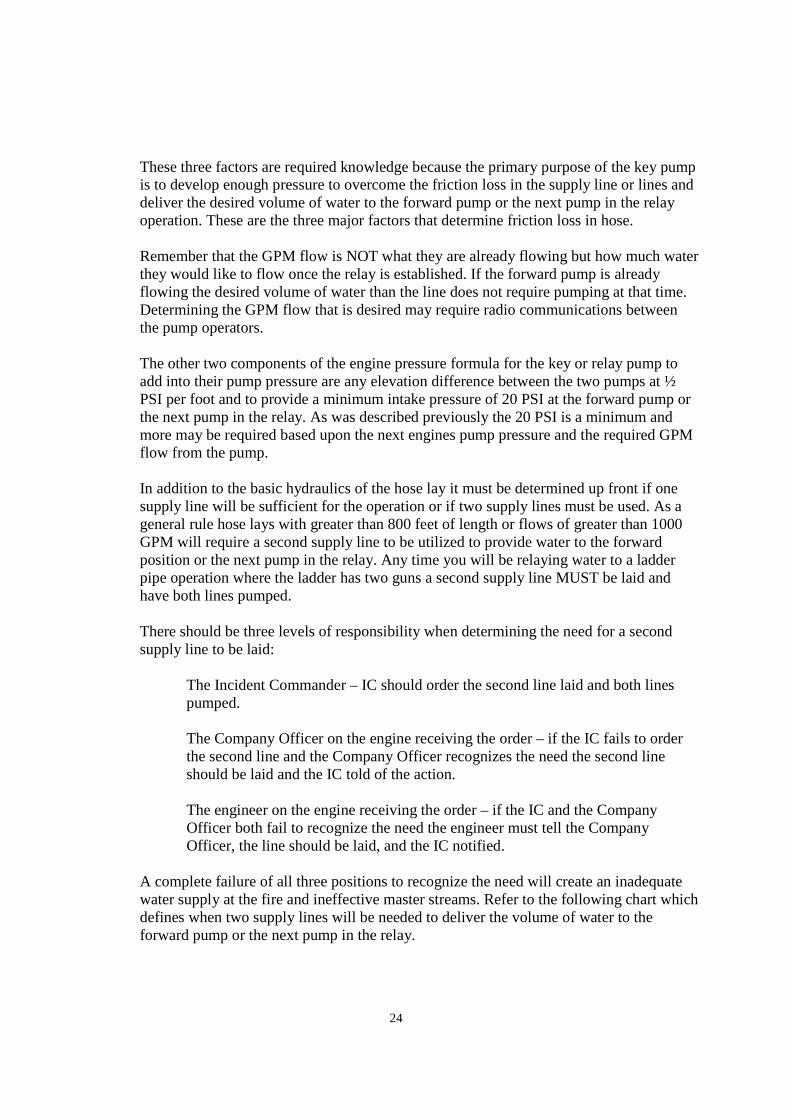
24
These three factors are required knowledge because the primary purpose of the key pump is to develop enough pressure to overcome the friction loss in the supply line or lines and deliver the desired volume of water to the forward pump or the next pump in the relay operation. These are the three major factors that determine friction loss in hose. Remember that the GPM flow is NOT what they are already flowing but how much water they would like to flow once the relay is established. If the forward pump is already flowing the desired volume of water than the line does not require pumping at that time. Determining the GPM flow that is desired may require radio communications between the pump operators. The other two components of the engine pressure formula for the key or relay pump to add into their pump pressure are any elevation difference between the two pumps at ½ PSI per foot and to provide a minimum intake pressure of 20 PSI at the forward pump or the next pump in the relay. As was described previously the 20 PSI is a minimum and more may be required based upon the next engines pump pressure and the required GPM flow from the pump. In addition to the basic hydraulics of the hose lay it must be determined up front if one supply line will be sufficient for the operation or if two supply lines must be used. As a general rule hose lays with greater than 800 feet of length or flows of greater than 1000 GPM will require a second supply line to be utilized to provide water to the forward position or the next pump in the relay. Any time you will be relaying water to a ladder pipe operation where the ladder has two guns a second supply line MUST be laid and have both lines pumped. There should be three levels of responsibility when determining the need for a second supply line to be laid:
The Incident Commander – IC should order the second line laid and both lines pumped. The Company Officer on the engine receiving the order – if the IC fails to order the second line and the Company Officer recognizes the need the second line should be laid and the IC told of the action. The engineer on the engine receiving the order – if the IC and the Company Officer both fail to recognize the need the engineer must tell the Company Officer, the line should be laid, and the IC notified.
A complete failure of all three positions to recognize the need will create an inadequate water supply at the fire and ineffective master streams. Refer to the following chart which defines when two supply lines will be needed to deliver the volume of water to the forward pump or the next pump in the relay.

25
When laying the second supply line the most effective method would be to reverse a supply line from the forward pump back to the hydrant. This is a good time to communicate with the forward pump operator to determine the desired GPM flow of the operation then follow these steps.
1. Locate and pull up to the forward pump. 2. Pull off enough supply line to butt the hose around the tires of the forward pump. 3. Lay the supply line to the forward pumps hydrant by following their supply line. 4. Spot your apparatus at the hydrant so you can connect from the Humat to your
intake. 5. The 6 inch rear main intake is the best option for this connection. 6. Connect the soft suction to the Humat and the intake. 7. Connect a 50 foot piece of supply line or the short length from an LDH discharge
to the female coupling on the bottom of the Humat. 8. If not already done, place the pump into gear. 9. Open the butterfly valve on the Humat. 10. Open the intake valve. 11. Open the LDH discharge to the Humat and pump the required pressure. 12. Use a 3 ½ inch double female coupling to connect the reverse line you laid to the
other LDH discharge. 13. Open that discharge and pump the required pressure.
Only steps 4 through 11 would be used to establish a relay pumping operation (pump a supply line) using a single supply line to the forward pump.
Stinger Lay and Relay Pumping
Stinger lays are used when the total hose lay will or may be greater than the 1000 feet carried on one Engine Company. This hose lay is also a good way to begin setting up a relay pumping operation. When the stinger lay is required, the first arriving engine selects a spot that is less than 1000 feet from their desired fire attack spot then lays from that location forward to the spot. The second arriving engine would then lay from a hydrant forward to the spot where the first company laid their line. The second company then connects their supply line into the rear main intake and the first engine’s supply line to an LDH discharge. The second engine is now the relay pump. A third company would then come in and pump the second company’s supply line at the hydrant if necessary. A second option for the second engine would be to lay a reverse line from the first engine’s supply line back to a hydrant where they would then pump the supply line. This option should only be used if the total GPM needed at the fire is less than about 500 GPM. Flows greater than 500 GPM will require a relay pump based upon an 1800 to 2000 foot hose lay. When large volumes are required the first option for setting up a relay pump operation should be used.
In general, no matter how a relay pump operation is developed the engines in the relay are responsible for the same things as a key pump on the hydrant. Those things are:

26
Pumping the friction loss in the supply line between their discharge and the intake of the next pump in line. Plus at least of 20 PSI for the minimum intake pressure for the next pump. Then adding or subtracting ½ PSI per foot of elevation difference between their pump and the next pump in line.
Pumping 5” hose
Pumping 5” hose in the Valley presents a few difficulties for PFD engines that must be over come. The first problem is having the ability to adapt to the 5” hose. All of the 5” hose currently used in the Valley has Storz couplings. Storz couplings are self locking quarter turn couplings that have no male of female ends. All of the Storz couplings will connect to each other and have no male or female orientation to them. When assigned to pump a supply line for a company that uses 5” hose an adaptor coupling must be secured from the forward pump unless you carry a 3 ½” threaded to %’ Storz adaptor on your apparatus. The next issue with this assignment is that companies which carry 5” hose do not use Humat valve. The 5” hose is attached directly to the hydrant using a 4.5” to 5” Storz adaptor. Upon receiving the order the company that will be pumping this supply line should take the following steps. Secure a 3 ½” threaded to 5” Storz adaptor. Spot the hydrant using the 6” rear main intake when possible.
Attach the soft-suction to the intake of the truck. Attach the 3 ½ to Storz adaptor to an LDH discharge.
Coordinate the shut down of the hydrant with the forward pump. Shut down the hydrant.
Connect the soft-suction to the steamer connection on the hydrant using a 4 ½” to 4” adaptor if necessary. Open the hydrant. Connect the supply line to the Storz adaptor on the LDH discharge. Open the LDH discharge and pump the calculated pressure.
Another issue with 5” hose in the Valley is that the maximum pressure that should be put into this hose is 180 PSI. At 180 PSI however, 1400 GPM can be supplied to the forward pump 1000 feet away. This is due to the tremendous decrease in friction loss when using 5” hose.
A second scenario for PFD engines is pumping 5” hose that has been laid out by the Hose truck. The PFD Hose truck carries 5000 feet of 5” hose and several couplings to adapt to our pumps and hydrants. The typical scenario for using the 5” hose from the Hose truck would be to place an engine company on a hydrant and lay the 5” supply line forward to another pumper in lieu of using 4” hose or even two 4” lines. There are several other scenarios that can be

27
used to implement the 5” hose into the water supply for the incident. The Hose truck carries the couplings needed to do the following things: 5” Storz to 4” female threaded. This coupling can be used to connect the 5” hose directly to the hydrant with out using a key or source pumper. This coupling can also be used to adapt the 5” hose directly into an intake on the apparatus. 5” Storz to 3 ½” threaded male couplings that are used to adapt the 5” hose into the intake of an apparatus while also using the 4” female to 3 ½” female intake adapter as would typically be used with a 4” supply line. 5” Storz to 3 ½” female couplings would be used on a discharge on the apparatus in order to pump the 5” hose to a relay pump or a forward pump. Also carried on the Hose truck are two large water thieves. These appliances have a 5” Storz on the inlet side and a gated 5” Storz on the opposite side. There are also 4 - 2 ½” gated discharges on the appliance to which 4” supply line can be attached and provide water supply to a pumper. These appliances are used as in-line “hydrants”.
Pumping Sprinklers
When assigned to pump the FDC that supplies the sprinkler system for the structure follow these basic steps.
Laying a water supply from a hydrant is imperative.
Use 2 ½” hose to make your connections. Connect the 2 ½” hose to all of the inlets on the system. With an obvious working fire or reports of a working fire:
Pump 150 PSI plus 5 PSI per floor in a multi-story structure. When there is nothing showing and there have been no reports from the interior companies of an active fire: Pump 100 PSI and wait for reports from the interior crews. If there is no fire, shut down the operation.
Upon reports of a fire, increase the pump discharge pressure to 150 PSI.
Pumping Standpipes
When having to pump standpipes it is necessary to determine weather the standpipe has a fire pump that is operating or not. When the system has an operating fire pump the pump operator should pump the system as they would a sprinkler system. Laying a water supply from a hydrant is imperative. Use 2 ½” hose to make your connections. Connect the 2 ½” hose to all of the inlets on the system. With an obvious working fire or reports of a working fire:
Pump 150 PSI plus 5 PSI per floor in a multi-story structure.

28
When there is nothing showing and there have been no reports from the interior companies of an active fire: Pump 100 PSI and wait for reports from the interior crews. If there is no fire, shut down the operation.
Upon reports of a fire, increase the pump discharge pressure to 150 PSI.
When the system does not have an operating fire pump the pump operator must use the following sequence. Laying a water supply from a hydrant is imperative. Use 2 ½” hose to make your connections. Connect the 2 ½” hose to all of the inlets on the system. The pump pressure to be used is determined by calculating all of the hose lay components on the discharge side of the pump as outlined in the Hydraulics chapter of this text. The PDP will include the nozzle pressure for the lines being used, the friction loss in the lines being used on the fire floor, the elevation difference between the pump and the fire floor, the appliance value for the standpipe, and the friction loss for the 2 ½” lines between the pump and the inlets of the standpipe system. Refer to the previous chapter on Hydraulics for additional information. If large volumes are required and high pressures must be pumped, a tandem pumping operation may need to be established. For further information see the section on tandem pumping later in this chapter.
Dual Pumping
Dual pumping occurs when two or more forward pumps are required to share the water supply from one hydrant. These situations are most likely to occur in the rural areas of the city, in mobile home parks, in some apartment complexes, and when a water supply is needed on a freeway mainline. Most pump operators believe the only way to make water come out of your pump is through a discharge. This is not true because as long as there is residual pressure on the intake side of the pump water will in fact flow out of an intake. Based upon this fact the connections between the two forward pumps when sharing one hydrant should be made by connecting the pumps intake to intake and NOT discharge to intake. As an example, pumper number 1 does not lay a supply line and begins to operate on the fire with a hand line. Pumper number 2 lays a supply line into a position near pumper number 1 and connects the supply line to their intake and begins to flow their own hand lines on the fire. Obviously pumper number 1 will need a water supply if they are to continue flowing water from their hand line. In order to share the water between the two pumpers or dual pump, the engineers would take a piece of supply line and connect the two pumps together intake to intake. This operation will require a 3 ½” double male for one end of the supply line in order to connect to the intake. Once connected the intakes are opened and the water now enters the intake of the first pump in line and that pump takes the volume of water it is flowing while the residual pressure exits the other intake

29
and into the intake of the second pump where they use the water they need to operate their lines. The minimum residual pressure to do this operation is about 40 PSI. The amount of water available to both pumpers is dictated by the hydrant and the length and diameter of the supply line. Should the two forward pumps need additional water the supply line can be pumped by a third pumper at the hydrant through the Humat valve. This operation is not limited to just two forward pumps sharing the single supply line but can be done with three or four pumpers if necessary. Connecting intake to intake instead of discharge to intake will cause the pump operators jobs to be easier and make the entire hose lay and scene safer for the firefighters operating on the hand lines.
Tandem Pumping
Tandem pumping operations are set up when large volumes of water AND high pressures are needed to deliver the water to the nozzles. The only likely scenario for this to occur is when pumping the standpipe system in a high rise structure where the fire pump has failed and large volumes of water are needed on the fire floor or floors. As was described earlier in this chapter centrifugal pumps flow their maximum volume at 150 PSI net pump pressure (or less). When the net pump pressure is increased the volume discharged is reduced. When dealing with a high rise structure, where the fire pump for the building has failed, the back pressure from the elevation can become very significant. As an example, when having to pump water to the 40th floor of a structure, the pressure needed to overcome the elevation alone would be 195 PSI. If you are flowing only two or three hand lines, the GPM flow AND the pressures can be achieved by one engine pumping the standpipe system. When the volumes required for fire suppression become significant a single engine can no longer provide both the pressure needed AND the increased volumes. AT this point is when a tandem pumping operation should be used. This operation basically uses two engines to create a large two-stage pump. Tandem pumping is set up with the following procedure: Two engines are placed next to one another. One engine connects a soft suction from the hydrant to their intake. The two engines are then connected by going through supply line from the discharge of the engine on the hydrant to the intake of the second engine. The second engine then uses the green high-pressure 2 ½” hose from their discharges to the FDC for the standpipe. The engine on the hydrant pumps a discharge pressure of 150 PSI to the intake of the second pump. The second pump begins to increase their PDP to the calculated pressure. As the second engine increases their PDP the first engine continues to increase their PDP to maintain 150 PSI at the intake of the second engine.

30
When the tandem pumping operation is set up it keeps the net pump pressures of the two pumps at or below 150 PSI. This allows for the second pump to produce 300 PSI of discharge pressure and still supply maximum volumes of water as needed on the fire floor or floors.
Drafting Operations
Drafting operations are used when the water supply is a static source such as a canal, irrigation ditch, river, pond, lake, or any other static source. Since centrifugal pumps do not pump air, the use of the priming pump, a positive displacement pump, will be necessary. Since the operation will require reducing the pressure in the pump and intake hose to a negative pressure of a vacuum the intake hose must be rigid or what is called a hard suction. When selecting a drafting location there are several things to consider. The stability of parking surface is an important consideration; every attempt should be made to park on asphalt or concrete when possible. If you must park on dirt, limit the amount of water that flows or overflows from the apparatus. Do not park so close to the source as to run the risk of the apparatus sliding into the source as the ground gets wet. The volume of water available from the static source must be enough to extinguish the fire without needing to relocate to another site. The depth of the static water source must be adequate enough to cover conventional strainers by 24 inches and still allow the strainer to be 24 inches above a muddy bottom. Shallower sources can be used if you have the proper equipment such as a shallow water or floating dock strainer. Irrigation ditches can be dammed up to provide better depth if needed. The distance from the center of the pump intake and the top of the water source or what is known as lift is also very important. The greater the lift the less the pump will be able to discharge in volume. There is also a maximum amount of lift. Theoretically a column of water can be lifted 33 feet at sea-level assuming an absolute vacuum can be created in the pump. Atmospheric pressure and elevation above sea-level are also factors in determining maximum lift as would be the condition of the fire pump as far as leaks are concerned. Priming pumps and fire apparatus are not capable of creating that absolute vacuum and there for realistically the maximum amount of lift in the Phoenix area is about 25 feet. Leave access for other apparatus that may need to operate around yours. Tankers should be able to enter the area driving forward as well as exit the area without having to backup for shuttling water from a static source to forward positions. During tanker shuttles the distance form the source to the fire should be a short as possible to facilitate the rapid movement of water to the forward positions. If operating at the forward position from a draft, ladders and other engine companies may need to gain access to the structure and the fireground as a whole.
The following equipment will (or may) be needed to establish a draft.

31
Hard suction A strainer to keep debris from entering the pump Rope or ladder to keep the strainer off of a muddy bottom Wood, cool can lid or beach ball to be used should a whirlpool develop over the strainer to keep air from entering the intake causing a loss of prime A shallow water strainer to be used when an adequate depth of water is unavailable A rubber mallet for insuring airtight connections A double male coupling (based upon the type of couplings on the hard suction) The priming pump on the apparatus must be functional May use oil or anti-freeze as a lubricant Check the lubricant tank weekly on apparatus Wheel chocks to aid in the stabilization of the apparatus
The drafting sequence is as follows:
Spot the apparatus in an appropriate location Consider stopping short of the location by a few feet if it will make the assembly of your drafting equipment easier, then move the apparatus forward while the firefighter(s) place the hard suction into the static source Place the transmission into neutral Set the parking brake DO NOT place the apparatus into pump at this time as it will require some time and possibly repositioning to set up the drafting operation Place the wheel chocks Connect the hard suction to the intake
Couple two sections of hard suction together as needed Use a rubber mallet to insure airtight connections
Use rope or a ladder to keep the strainer off of a muddy bottom A minimum of 24 inches above bottom of the source A minimum of 24 inches below the surface of the source 24 inches is required for the pump to flow its rated capacity, if the volume of water to be flowed will be less, the minimum distance will be reduced accordingly These distances don’t apply to shallow water strainers
Close ALL of the valves on the apparatus. This would include The tank-to-pump valve All discharge valves All bleeder valves The tank fill valve Pump cooler valves Indirect engine coolers Pump drains Intake valves
Open ONLY the intake valve being used for the drafting operation Place the truck into pump gear Return to the pump panel

32
Check the “okay to pump” light Place PSG into Throttle or RPM mode Increase the throttle to 1000 - 1200 RPM Activate priming pump by pulling the handle outwards
You must continue to pull the handle at all times while establishing a prime On many apparatus the priming pump will continue to run even if you let go of the handle. The pump is not fully engage and will not develop the needed vacuum It may be necessary to push the handle back in once you’ve established the prime to get the priming pump to shut off
Watch the main discharge pressure gauge for a reading to develop and become steady Listen for a change in the sound of the priming pump
A higher pitch will be heard at the beginning as the pump removes air from the pump The pitch will then fluctuate between high and low as air and some water are being discharged from the pump The pitch will become low and steady once the pump is discharging water only
Watch the hard suction to see if water is moving up the hose All hard suction will “sag” as the weight of the water effects the hose
Some hard suction is clear or partially clear so you can see the water move up the hose
Return PSG to pressure or PSI mode Open the desired discharge and throttle to required engine pressure The apparatus should now pump as it does on hydrant or tank water The intake gauge will read zero and move slightly below zero as a greater volume of water is flowed from the pump Unless absolutely necessary, DO NOT fill your booster tank with dirty or contaminated water

33
Shutting down the operation Reduce the throttle to idle Turn off PSG system Close all the discharge gates being used Bleed the pressure from the discharges through the bleeder valves or the nozzles Check the gauges on the pump panel Take the truck out of pump gear Remove the hard suction from intake Allow the pump and the plumbing to drain If contaminated water entered the tank;
Drain the tank. Flush the tank, pump and plumbing with fresh clean water from a hydrant as needed Check the intake screens and the fog nozzles for rocks, twigs and other obstructions after using contaminated water
Secure all the hose and equipment used during the incident.

DRIVER TRAINING PROGRAM
Engineer Move-Up Academy
PHOENIX FIRE DEPARTMENT TRAINING MANUAL
Revised 3/08 Page 1
American LaFrance/LTI Tillered Ladders The following section covers aerial operations for American LaFrance/LTI Tillered Aerial Ladders. This section illustrates the basic procedure/method in outrigger set-up and elevating, rotating and extending the aerial for its operation. It is recommended that the reader refer to the reference guides and the apparatus manual for further information/explanation.
I. Placing an aerial into operation. A step-by-step description.
A. Set parking brake immediately after apparatus placement--spot clear of obstacles. Apparatus should be on concrete or asphalt to operate aerial. NOTE: Operating aerial ladders on any surface other than concrete or asphalt is extremely hazardous due to unknown
soil conditions and the rapidly changing conditions of the soil caused by runoff from supply lines or inclement weather.
B. Place transmission in neutral. Engage power take-off and ladder power using switches on the overhead console on the engineers side. C. Observe all gauges before leaving cab to assure engine is operating properly (rpm, oil pressure, air pressure, temperature, etc.). D. Use wheel chocks at both front wheels. E. Use outrigger controls located mid-truck behind first outrigger, to lower outriggers on each side. F. If personnel are available, use as spotters when setting and retracting outriggers. NOTE: Always use ground plates regardless of surface conditions. Turn handles of ground plates towards the truck. G. As hand controls are operated, observe outriggers movement to prevent injury to personnel and equipment. Outriggers should move safely and smoothly without sudden movement. High idle switch can be engaged for faster outrigger deployment. H. After front outrigger has rotated out fully, outrigger pin must be placed in outrigger pin-holder, making sure that pin contacts the micro-switch. NOTE: The outrigger jacks will not extend down if pin doesn't hit the micro-switch.

DRIVER TRAINING PROGRAM
Engineer Move-Up Academy
PHOENIX FIRE DEPARTMENT TRAINING MANUAL
Revised 3/08 Page 2
I. Extend outrigger jacks down until the bulge in the rear tires has been removed and the green indicator lights come on. Set one side, and then proceed to set the other side. Both sides may be done at the same time provided adequate personnel are available. J. Use truck mounted levels to level the truck. Make sure that the float is in the green area of the truck mounted level. K. Be sure that green indicator lights are on for each outrigger. Set all pins in outrigger jacks. (Leave approximately ¼” minimum clearance above locking pin when inserting through holes in the outrigger.) Once all green lights are on for each outrigger, the power is automatically transferred to the pedestal and bucket.
II. Aerial ladder operation from pedestal position.
A. Control pedestal on the turntable has 3 aerial control levers; elevate, rotate and extend. Once the dead man pedal has been depressed the levers will operate the ladder. Hand placement is very important when operating these controls. Both hands should be placed on the lever to operate controls. Operations should be done smoothly. NOTE: Before the aerial is raised, it is important to check fire/rescue pin placement on the aerial. Operator should know if the pin on the aerial is in rescue or fire position for effective aerial placement. B. Controls are always operated in the following sequence: elevate, rotate and extend. NOTE: Experience and extreme caution should be used before using high idle switch.
1. Before elevating an aerial, check for overhead obstructions. If personnel are available, use as spotters when placing aerial into service and when bedding aerial into cradle. Elevate aerial to desired angle with control lever. 2. Rotate aerial to desired position with control lever. Make sure aerial does not rotate into truck cab and is clear of obstructions. 3. Extend aerial to desired height with control lever. Make sure aerial is clear of all obstructions. 4. After aerial is in deployed small adjustments can be made in regards to elevation, rotation or extension to gain proper aerial placement.
C. The truck is equipped with automatic aerial locks, which are activated when the rung alignment light is on.

DRIVER TRAINING PROGRAM
Engineer Move-Up Academy
PHOENIX FIRE DEPARTMENT TRAINING MANUAL
Revised 3/08 Page 3
III. Shut down procedures.
A. If personnel are available, use as spotters for bedding of aerial. Always check for all possible overhead obstructions. B. Retract, rotate and lower the aerial, reverse order of aerial deployment. C. Use spotter for final placement of aerial into cradle of truck. Once the aerial is bedded in cradle, hold elevate control lever down for 3-5 seconds. This will secure aerial in cradle and keep aerial from bouncing while driving. D. Once aerial is bedded the outriggers can be retracted. Power is automatically transferred to outriggers. E. Remove pins from outriggers and place back in pin holders. F. Raise outriggers using spotters when available. If possible raise all four
jacks off ground plates simultaneously using personnel at both outrigger control panels.
G. Retract all outrigger beams. H. Stow wheel chocks. I. Stow ground plates. J. Check all engine gauges. K. Disengage power take-off (PTO) and ladder power.

DRIVER TRAINING PROGRAM
Engineer Move-Up Academy
PHOENIX FIRE DEPARTMENT TRAINING MANUAL
Revised 2/09 Page 1
American LaFrance/LTI Aerial Platforms The following section covers aerial operations for American LaFrance Aerial Platforms. This section illustrates the basic procedure/method in outrigger set-up, elevating, rotating and extending the aerial for its operation. It is recommended that the reader refer to the reference guides and the apparatus manual for further information/explanation.
I. Placing an aerial platform into operation. A step-by-step description.
A. Set parking brake immediately after apparatus placement--spot clear of obstacles. Apparatus should be on concrete or asphalt to operate aerial. NOTE: Operating aerial ladders on any surface other than concrete or asphalt is extremely hazardous due to unknown
soil conditions and the rapidly changing condition of the soil caused by runoff from supply lines and or inclement weather.
B. Place transmission in neutral. Engage power take-off and ladder power using switches on the overhead console on the engineers side. C. Observe all gauges before leaving cab to assure engine is operating properly (rpm, oil pressure, air pressure, temperature, etc.). D. Use wheel chocks on both front wheels. E. Use outrigger controls located mid-truck. The control panels are between the front and rear outriggers. There is an outrigger control panel for both sides of the truck. F. If personnel are available, use as spotters when setting and retracting outriggers. NOTE: Always use ground plates regardless of surface conditions. Turn handles of ground plates towards the truck. G. As hand controls are operated, observe outriggers movement to prevent injury to personnel and equipment. Outriggers should move safely and smoothly without sudden movement. High idle switch can be engaged for faster outrigger deployment. H. Extend outrigger beams first, make sure beams are fully extended before lowering outrigger jacks. After all four beams have been extended, lower outrigger jacks to touch ground plates. Adjust ground plates as needed to allow outrigger jacks to be placed in center of ground plates.

DRIVER TRAINING PROGRAM
Engineer Move-Up Academy
PHOENIX FIRE DEPARTMENT TRAINING MANUAL
Revised 2/09 Page 2
I. Extend outrigger jacks down until the bulge in the rear tires has been removed and the green indicator lights come on. Set one side, and then proceed to set the other side. Both sides may be done at the same time provided adequate personnel are available. J. Use truck mounted levels to level the truck. Make sure that the float is in the green area (3% of grade) of the truck mounted level. K. Fully deploy front bumper jack from engineer’s side. Deploy until green light comes on and Hold for 5 seconds. L. Be sure that green indicator lights are on for each outrigger. Set all 4 pins in outrigger jacks. (Leave approximately ¼” minimum clearance above locking pin when inserting through holes in the outrigger.) Once all green lights are on for each outrigger and bumper jack, the power is automatically transferred to the pedestal and bucket.
NOTE: The newer American LaFrance Ladders (Ladder 20 & 50) have a remote outrigger control panel feature, which allows 1 person to set outriggers from the rear/back of the truck. The remote control panel is located in the left rear compartment of the truck. Control panel can be operated approx. 20 ft. behind the truck. All set-up and safety procedures are the same when using 1 person set-up.
M. Control pedestal on the turntable has 3 aerial control levers; elevate, rotate and extend. Once the dead man pedal has been depressed the levers will operate the ladder. Hand placement is very important when operating these controls. Both hands should be placed on the lever to operate controls. Operations should be done smoothly. N. Controls are always operated in the following sequence: elevate, rotate and extend. NOTE: Experience and extreme caution should be used before using high idle switch, especially with personnel in the aerial platform.
1. Before elevating an aerial, check for overhead obstructions. If personnel are available, use spotters when placing aerial into service and when bedding aerial into cradle. Elevate aerial to desired angle with control lever. 2. Rotate aerial to desired position with control lever. Make sure aerial does not rotate into truck cab and is clear of obstructions. 3. Extend aerial to desired height with control lever. Make sure aerial is clear of all obstructions.

DRIVER TRAINING PROGRAM
Engineer Move-Up Academy
PHOENIX FIRE DEPARTMENT TRAINING MANUAL
Revised 2/09 Page 3
4. After aerial is in deployed, small adjustments can be made in regards to elevation, rotation or extension to gain proper aerial placement.
O. The truck is equipped with automatic aerial locks; therefore the aerial will hold its position once it's in place.
II. Placing the aerial platform into operation from the platform position.
A. Follow Section I instructions for set-up steps A. thru L. B. Make sure the Platform Control Power knob is pulled up to the on position. The Platform Control Power knob is at the control panel at the turntable pedestal. This will allow aerial platform control levers to operate. C. Once in the platform, the aerial can be operated in the same manner as from the turntable pedestal. Follow same instructions for aerial placement: elevate, rotate and extend. Use experience and extreme caution when using the high idle switch. There is no dead man pedal in the platform, control levers are used by pulling up on a collar on the control levers.
NOTE: This aerial can perform simultaneous actions such as elevate and rotate at the same time.
III. Placing the aerial platform into operation using the short jacking method.
A. Follow Section I instructions for set-up steps A. thru G. B. Set one side of outriggers completely, on the side with the most room for deployment. C. Both front tires must remain on the ground. D. On the opposite side that has restricted room for deployment, the outriggers must be short jacked, (beams not fully extended out). The interlock override switch must be used while placing jacks down onto ground plates. E. Use override switch to deploy front bumper jacks. F. From this point on, the ladder must have the override switch held on to move the aerial from either the turntable pedestal or the platform position. There are override switches at both positions. G. The aerial must be operated over the fully extended side of the outriggers. NEVER operate aerial over the short jacked side.

DRIVER TRAINING PROGRAM
Engineer Move-Up Academy
PHOENIX FIRE DEPARTMENT TRAINING MANUAL
Revised 2/09 Page 4
IV. Shut down procedures.
A. If personnel are available, use spotters for bedding the aerial. Always check for all possible overhead obstructions.
B. Retract, rotate, and lower the aerial, reverse order of aerial deployment. C. Use spotter for final placement of aerial into cradle of truck. Once the
aerial is bedded in cradle, hold elevate control lever down for 3-5 seconds. This will secure aerial in cradle and keep aerial from bouncing while driving.
D. Once aerial is bedded, the outriggers can be retracted. Power is
automatically transferred to outriggers. E. Remove pins from jacks and place back in pin holders on jacks. F. Raise bumper jack. G. Raise outrigger jacks one side at a time in a step method or raise all four
jacks together, to prevent air bag suspension damage. Use spotters when available.
H. Retract all four outriggers beams. I. Stow wheel chocks. I. Stow ground plates. J. Check all engine gauges. K. Disengage Power Take Off (PTO) and Ladder Power.

DRIVER TRAINING PROGRAM
Engineer Move-Up Academy
PHOENIX FIRE DEPARTMENT TRAINING MANUAL
Revised 10/15 Page 1
Pre-trip Inspection / Daily Check
Engine Compartment Leaks (oils, coolant or fuel) Engine oil level (at least 30 min after shut down) Transmission fluid level (when engine is running, in neutral, at operating temp) Washer fluid level Coolant level Power steering fluid level Belts (tightness, condition) Hoses (leaks, condition) Wiring (damaged, loose)
Under the Truck Tires:
Condition (evenly worn, cuts and/or damage to tread or sidewalls) Tread depth (DOT min 4/32” front and 2/32” rear, call RM-14 at 6/32”) Tire pressure (listed at fender)
Rims and lug nuts (cracks, bent, loose) Hub oil seals/Axle seals (oil level, leaks) Batteries (leaks, loose connections) Air tanks (drain, check for moisture) Steering box (leaks, loose connections) Steering linkage (loose, bent) Leaf springs (cracks, broken) Spring mounts (loose, bent, misaligned) Air bags (leaks, leans) Shock absorbers (leaks, loose) Air and electric lines (damaged, loose) Brake chambers (damaged, loose) Brake drums/rotors (long cracks, or cracks over the edge) Brake pads/shoes (cracks, soaked with oil or grease, thickness ¼” minimum) Slack adjusters:
(1” to 1 ½” is normal, for a manual pull) (1 ½” to 2” for brake application) (Check angle between the push rod and adjuster arm. It should be a little over 90 degrees when brakes are released and not less than 90 degrees when the brakes are applied.)
Exhaust system (leaks, loose) Drive shaft and U-Joints (condition) Differential (leaks, condition) Frame (bends, cracks) Fuel tank (securely mounted, not damaged, or leaking)

DRIVER TRAINING PROGRAM
Engineer Move-Up Academy
PHOENIX FIRE DEPARTMENT TRAINING MANUAL
Revised 10/15 Page 2
Inside Cab / Engine running Lights/Siren Horn(s) Steering wheel play Parking brake Dash lights Oil pressure Voltmeter Fuel level Air pressure Seat adjustment Windshield Mirrors Wipers/Washers Air conditioner Heater/Defroster Radio (channels and volume) Seatbelts and warning signal Compartment door open warning light / buzzer
Outside the Truck Emergency lights, and traffic signal preemption system (opticom) Lights: (headlights, taillights, brake lights, four way flashers, turn signals, and clearance
lights)
Air Brake Test Follow Air Brake Test Process
Pump Panel Engage pump Check governor override switch Check governor enable switch Check all gauges:
(Oil pressure, water temp, voltmeter, tachometer, intake, and discharge) Open tank to pump Open tank fill (to circulate water) Operate Priming Pump Check water and foam tank levels Operate pressure governor Flow water/foam Check panel lights Disengage pump Open and close discharge gates Open and close drains

DRIVER TRAINING PROGRAM
Engineer Move-Up Academy
PHOENIX FIRE DEPARTMENT TRAINING MANUAL
Revised 10/15 Page 3
Compartments EMS equipment Fire fighting equipment (couplings, hose, and nozzles) Emergency equipment (cones, flares, extinguisher)
Top of the Truck
Water tank level Foam tank level Fire fighting equipment (stang gun, hose, nozzles) Antennas Lights
Ladder Trucks PTO/Ladder power Generator and lighting Jack plates Outriggers (leaks, condition) Hydraulic lines (leaks, bulges) Hoisting cylinders (leaks, condition) Hydraulic fluid level Air cylinder and connections Turntable and platform controls

DRIVER TRAINING PROGRAM
Engineer Move-Up Academy
PHOENIX FIRE DEPARTMENT TRAINING MANUAL
Revised 10/15 Page 4
Air Brake Test / Daily Check
*Level ground *Place wheel chalks
Test air leakage rate Air tanks full, engine off, and power on Release parking brake and time the air pressure drop
(loss rate should be less than 2 psi in 1 minute for single vehicles and less than 3 psi in 1 minute for combination vehicles.)
Apply the foot brake firmly and time the air pressure drop (after the initial drop, pressure should not drop more than 3 psi in 1 minute for single vehicles or more than 4 psi for combination vehicles.)
Test Low-Pressure Warning Signal Engine off, power on, parking brake off Reduce air tank psi by pumping the brake pedal
(low-pressure warning signal must come on before reaching less than 60 psi.)
Check that the spring brakes come on automatically Engine off, power on, parking brake off Reduce air tank pressure by pumping the brake pedal
(“Parking Brake” knob should pop out when the air pressure falls to within 20-40 psi) Check rate of air pressure buildup Engine on, parking brake on, high idle on Pressure should build up FROM 85 to 100 psi within 45 seconds in dual air systems Check air compressor governor cut-in and cut-out pressures Engine on (at idle), parking brake off, Reduce air tank pressure by pumping the brake pedal
(the governor should cut-in at about 100 psi and pressure will begin to rise. The governor should cut-out at about 120-125 psi.)
*Remove wheel chalks* Test parking brake Engine on, parking brake on Put vehicle in drive and gently pull forward to test if parking brake will hold Test service brakes Engine on, parking brake off With vehicle in drive, slowly move forward (about 5 mph), and apply brakes firmly
(Note any vehicle pulling to one side, unusual feel, or delayed stopping action.)