CHAPTER 12 SURVIVAL RADIOS AND BEACONS - …€¦ · · 2016-09-22CHAPTER 12 SURVIVAL RADIOS AND...
25
12-1 CHAPTER 12 SURVIVAL RADIOS AND BEACONS Today’s rescue procedures are based on early detection and fast recovery of the surviving aircrewman. Once an aircrewman has been placed into a survival situation, it is essential they are located as soon as possible, and the key items for accomplishing that goal are the survival radios and emergency beacons. Navy aircrewmen carry survival radios as part of their personal survival equipment. The survival radio provides two-way communication between the aircrewman and the Search and Rescue (SAR) forces. You must check each aircrewman’s radio when you perform the 90-day calendar inspection on aircrew survival equipment. Emergency beacons are transmitters that have no receive capability. SAR forces equipped with a Direction-Finding (DF) receiver can determine the bearing to the broadcasting beacon. Beacons incorporating technological advances have the ability to transmit digital data containing positional coordinates and other information to improve the probability of a successful recovery. This chapter describes the operation and inspection of the PRC-149 non-combat radio, the PRQ-7 combat radio, and the URT-140 emergency beacon. LEARNING OBJECTIVE Upon completion of this chapter, you will be able to identify and describe survival radios and beacons. AN/PRC-149 RADIO SET The AN/PRC-149 radio set (Figure 12-1) is a non-combat radio that combines a voice transceiver at selectable frequencies of 121.5 MHz, 243.0 MHz, and 282.8 MHz with a multi-mode personal locator beacon that simultaneously transmits the older 121.5 MHz and 243.0 MHz beacon frequencies with the newer digital 406.025 MHz beacon frequency. An embedded GPS receiver provides positional data within a 300-foot accuracy that is coded into the digital beacon transmissions. Global Positioning System (GPS) initial acquisition time takes less than 130 seconds. The radio set can also used by rescue swimmers when configured with a C- 12631/PRC-149 Swimmer Control Unit (SCU). Description The AN/PRC-149 radio set is capable of operating at the following frequencies: 121.5 MHz civilian emergency frequency 243.0 MHz military emergency frequency 282.8 MHz international emergency voice transceiver frequency 406.025 MHz international emergency message frequency
Transcript of CHAPTER 12 SURVIVAL RADIOS AND BEACONS - …€¦ · · 2016-09-22CHAPTER 12 SURVIVAL RADIOS AND...

12-1
CHAPTER 12
SURVIVAL RADIOS AND BEACONS
Today’s rescue procedures are based on early detection and fast recovery of the surviving aircrewman. Once an aircrewman has been placed into a survival situation, it is essential they are located as soon as possible, and the key items for accomplishing that goal are the survival radios and emergency beacons.
Navy aircrewmen carry survival radios as part of their personal survival equipment. The survival radio provides two-way communication between the aircrewman and the Search and Rescue (SAR) forces. You must check each aircrewman’s radio when you perform the 90-day calendar inspection on aircrew survival equipment.
Emergency beacons are transmitters that have no receive capability. SAR forces equipped with a Direction-Finding (DF) receiver can determine the bearing to the broadcasting beacon. Beacons incorporating technological advances have the ability to transmit digital data containing positional coordinates and other information to improve the probability of a successful recovery.
This chapter describes the operation and inspection of the PRC-149 non-combat radio, the PRQ-7 combat radio, and the URT-140 emergency beacon.
LEARNING OBJECTIVE
Upon completion of this chapter, you will be able to identify and describe survival radios and beacons.
AN/PRC-149 RADIO SET
The AN/PRC-149 radio set (Figure 12-1) is a non-combat radio that combines a voice transceiver at selectable frequencies of 121.5 MHz, 243.0 MHz, and 282.8 MHz with a multi-mode personal locator beacon that simultaneously transmits the older 121.5 MHz and 243.0 MHz beacon frequencies with the newer digital 406.025 MHz beacon frequency. An embedded GPS receiver provides positional data within a 300-foot accuracy that is coded into the digital beacon transmissions. Global Positioning System (GPS) initial acquisition time takes less than 130 seconds.
The radio set can also used by rescue swimmers when configured with a C-12631/PRC-149 Swimmer Control Unit (SCU).
Description
The AN/PRC-149 radio set is capable of operating at the following frequencies:
121.5 MHz civilian emergency frequency
243.0 MHz military emergency frequency
282.8 MHz international emergency voice transceiver frequency
406.025 MHz international emergency message frequency

12-2
Figure 12-1 — PRC-149 radio set.
The radio set weighs 34 ounces (excluding the batteries) and measures 8.25 inches long, 4 inches wide, and 2 inches thick.
Main Electronics Housing
The main electronics housing accommodates the radio controls, LED indicators, speaker, microphone, and GPS antenna.
Blade Antenna Assembly
The radio is each fitted with a stowable blade antenna used for transmitting beacon signals and for receiving and transmitting voice signals.
Batteries
The batteries can be replaced without the use of special tools and while the user is wearing gloves. The radio set is designed to prevent damage either to the batteries or the radio should the batteries be installed incorrectly.

12-3
Wrist Strap and Storage Pouch
The radio set includes a wrist strap to prevent inadvertent loss. A nylon storage pouch for a radio headset is attached to the wrist strap.
Swimmer Control Unit (SCU)
The SCU consists of a radio control cable with a radio set connector as well as a radio control box incorporating a speaker/microphone, headset contacts, volume up and down switches, and a push-to-talk switch. The SCU includes its own integral antenna. The radio set and the SCU are intended to be used in an LPU-28 Aircrew Life Preserver. In the swimmer radio configuration, an SCU is connected to the radio set in place of blade antenna assembly by the SCU’s integral cable. The radio set is stored in the pocket on the front of the life preserver. The back of the SCU control box is firmly attached to the LPU-28 Aircrew Life Preserver via hook material (Velcro).
Operation
The PRC-149 is meant to be held in the right hand, three to five inches from the operator’s face. Speech should be directly into microphone with the antenna pointed generally vertical and perpendicular to the line of sight to the SAR aircraft. The directions are located on the operating instructions label attached to the radio set (see Figure 12-1).
The mode selector switch (Figure 12-2) selects the radio set operating mode. The mode selector switch is a push-and-turn type switch to prevent inadvertent activation of the radio or switching from one mode to another. The radio set operates in six operating modes:
OFF
GPS
AM transceiver
Triple-frequency beacon
406 MHz beacon
BIT
The push-to-talk (PTT) and VOLUME UP/DOWN switches are mainly used to control the voice communication traffic when operating in the AM transceiver mode.

12-4
Figure 12-2 — PRC-149 radio set controls.
The radio set has two types of built-in-tests (BIT).
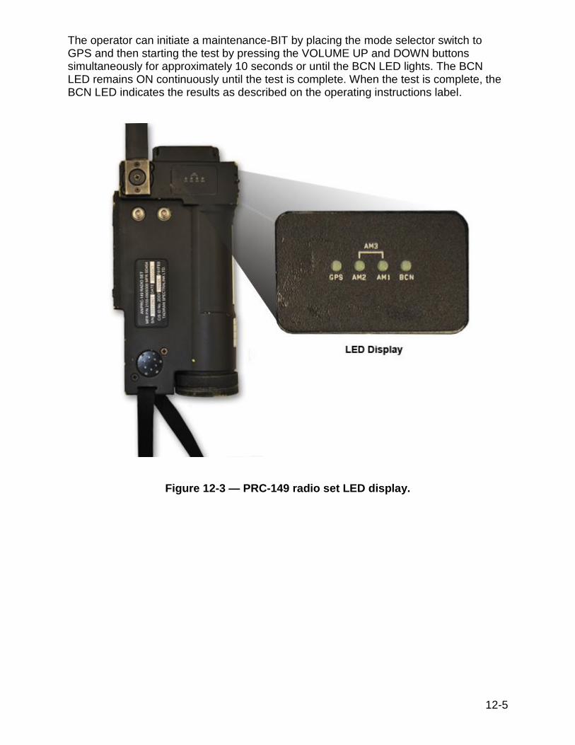
A power-up BIT is initiated each time the mode selector switch is rotated from the OFF position to any operating mode position. This test verifies that the processor can read and write from its memory and that basic processor communication with its peripherals is working. This test takes less than two seconds, during which time all four LEDs (Figure 12-3) are ON. If the BIT passes, all four LEDs are turned OFF for approximately two seconds before the selected mode of operation begins, at which time the LEDs function accordingly for the mode of operation. If the BIT fails, all four LEDs remain ON continuously.
A maintenance BIT tests the radio set and verifies that:
Battery voltage is above threshold under full load, ensuring four hours of operation
Output power of all beacons is within tolerance limits
All synthesizers are locked
The AM transmitter output power is within tolerance limits for all channels
The AM receiver is operating on all channels
12-5
The operator can initiate a maintenance-BIT by placing the mode selector switch to GPS and then starting the test by pressing the VOLUME UP and DOWN buttons simultaneously for approximately 10 seconds or until the BCN LED lights. The BCN LED remains ON continuously until the test is complete. When the test is complete, the BCN LED indicates the results as described on the operating instructions label.
Figure 12-3 — PRC-149 radio set LED display.

12-6
Inspection
NOTE
Removing the housing cover invalidates the warranty and might affect radio beacon set’s integrity.
The radio set does not require scheduled maintenance beyond cleaning exterior surfaces, scheduled actuation of the BITs, and battery replacement.
Local repair of the unit is limited to replacing batteries, the battery holder assembly, the blade antenna assembly, and the mode selector switch knob in the event of damage.
CAUTION
Do not ship batteries with the unit. Always remove batteries before shipping.
NOTE
Ship all accessories including mode selector switch locking clip and battery holder assembly but without batteries
together with the radio set. Do not ship the SCU with radio set. Radio sets returned for repair should be placed in POOL
status in JSETS.
For the latest inspection requirements, see NAVAIR 16-30PRC149-1.
Preflight/Postflight inspections include a visual inspection of the PRC-149 and cleaning if needed. The preflight also requires a power-up BIT.
Every 90 days, a maintenance BIT will be performed on the PRC-149.
Every 180 days, perform a GPS acquisition check on the PRC-149 and inspect the batteries and holder.
Every 3 years, replace the batteries in the PRC-149 radio.
AN/PRQ-7 RADIO SET
Combat Survivor/Evader Location (CSEL) System
The CSEL system is composed of three segments:
Over-the-Horizon (OTH) segment
Ground segment
User segment

12-7
The AN/PRQ-7 radio set is part of the CSEL System User segment as shown in Figure 12-4. The CSEL system uses GPS, other national and international satellite systems, and national assets to provide geo-position and radio communication. The primary use of the CSEL system is for search and rescue.
OTH Segment
The Over-The-Horizon (OTH) Segment operates over the following Satellite Communication (SATCOM) systems:
Ultra High Frequency (UHF) SATCOM
Cosmicheskaya Systyema Poiska Avariynich Sudov - Search & Rescue Satellite Assisted Tracking (COSPAS-SARSAT)
The UHF SATCOM mode supports two-way secure messaging/geo-position between an AN/GRC-242 Radio Set Base Station and the AN/PRQ-7 Radio Set through a UHF SATCOM channel. The Low Probability of Exploitation (LPE) mode supports one-way secure messaging/geo-position from the radio using national assets. LPE radio transmissions are acknowledged by the Joint Search and Rescue Center (JSRC) via the base station and UHF SATCOM satellite. The SARSAT mode operates over the international COSPAS-SARSAT satellite system providing non-secure data and beacon transmissions and is intended for emergency coverage at latitudes above 70° where UHF SATCOM coverage is usually not available, as well as backup coverage through the civil Search and Rescue (SAR) system.
Ground Segment
The Ground Segment is composed of CSEL workstations and the global Ground Distribution Network (GDN) (Secret Internet Protocol Router Network [SIPRNET]) that interconnects with a base station. A CSEL workstation is a stand alone or existing workstation that supports the Defense Information Infrastructure (DII) Common Operating Environment (COE) and is running the CSEL JSRC application segment software. The CSEL JSRC software can operate simultaneously with other mission applications. The GDN provides a highly reliable and timely global connection between all CSEL ground elements by utilizing the existing Defense Information System Network (DISN) with DII COE compatible communications protocols.

12-8
Figure 12-4— CSEL system architecture.
User Segment
The User Segment equipment consists of the AN/PRQ-7 radio, J-6431/PRQ-7 Radio Set Adapter (RSA) (also referred to as the loader), CSEL Planning Computer (CPC), and CPC Control Program software. The radio provides data communication, geo-positioning, voice, and beacons. The RSA provides the physical interface between the CPC and two operational radios. One radio serves as the reference in the RSA to acquire and store GPS almanac, ephemeris, and time for transfer to the other (target) radio. The CPC hosts the CPC Control Program software and with the RSA is used to

12-9
load the radios. A Windows operating environment is used to load a target radio with mission specific data (communications frequencies and channels, datums and waypoints, an optional user password, etc.), transfer GPS data from the reference to the target radio, and control GPS key loading. Loading current almanac and ephemeris data speeds the satellite acquisition process in the GPS receiver. Transferring current GPS data accelerates the calculation of user position.
Description
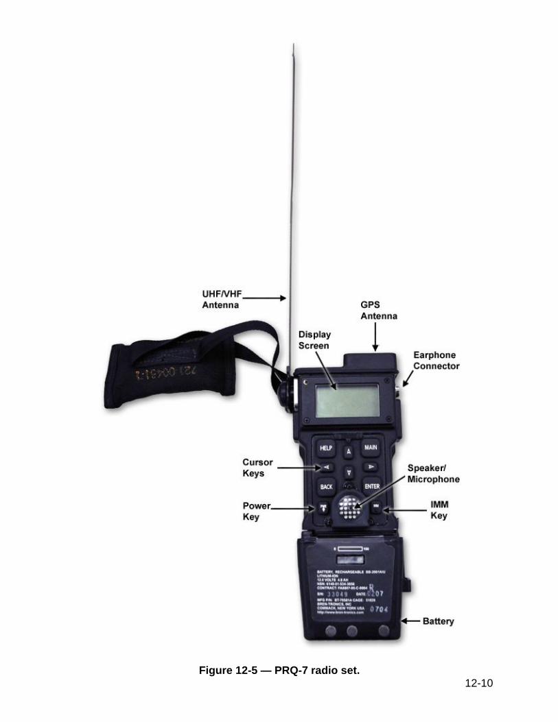
The PRQ-7 radio set consists of the radio with a main battery (Figure 12-5), an earphone, a strap, and a pouch attached to the rear of the radio.
The PRQ-7 radio can withstand conditions associated with aircrew emergency egress, such as shock, vibration, and g-forces. The radio will withstand salt-water immersion at one meter for twelve hours and at ten meters for five minutes. It will operate at the temperature range of -20 °C to +55 °C, withstand the g-forces associated with ejection, withstand rapid decompression, and operate after four-foot drops onto concrete. The radio will operate after field biological and chemical decontamination with a water and chlorine bleach solution.
The radio is powered by a main battery providing approximately 96 hours of operation. The radio may be powered from a non-rechargeable Lithium/Manganese battery or a rechargeable Lithium Ion battery. The non-chargeable battery indicates its remaining battery life and alerts the user when battery energy is getting low. Non-rechargeable battery indications are displayed on the radio. The rechargeable battery has a state-of charge indicator on the face of the battery consisting of a five-segment Liquid Crystal Display (LCD) bar graph readout.
Frequencies, waypoints, crypto keys, and messages are maintained in a volatile memory using power from the main battery pack. During battery pack changes, a capacitor maintains volatile memory. A fully charged capacitor is able to maintain volatile memory for 10 to 20 minutes. The capacitor is charged when the main battery is installed.
A unique, non-changeable handheld radio identification (HHRID) number set at the factory identifies each radio. Transmissions are automatically tagged with this identification number and encrypted using traffic encryption keys (TEK) unique to each radio. This allows each radio to be individually tracked at the JSRC.
The radio incorporates National Security Agency (NSA) approved communications security (COMSEC) techniques to prevent crypto keys from being extracted. An NSA- approved encryption algorithm is used to protect UHF SATCOM and LPE transmissions. A zeroize feature is included to permit the user to purge volatile memory.
The radio includes a password feature to control its use. Password entry is required each time the radio is turned ON. Three password entry attempts are allowed each time the radio is turned ON. After three (3) failed password entry attempts, the radio zeroizes and powers down.
12-10
Figure 12-5 — PRQ-7 radio set.

12-11
In UHF SATCOM mode, the system provides location data to the CSEL Workstation once the radio user’s initial message has been received by the base station. To provide initial alert and position information to a recovery unit, a user must deploy the antenna, turn ON the radio, orient the radio, and depress the Immediate (IMM) Transmit key. On the first IMM key depression, the radio enters into a sequence that steps the user through a series of actions. The sequence is known as the Immediate-Fix-Immediate (IFI) Auto-sequence. The IFI establishes the user into the CSEL network, provides initial user authentication, and reports GPS position to the CSEL Workstation. The CSEL system delivers a message from a radio to a CSEL Workstation and returns within approximately ten minutes. The user is notified within twelve seconds that the base station has received the transmission.
The radio GPS receiver obtains geo-positioning information that is included in every data transmission. Data transmissions are received at the base station and transmitted to theater command centers and search and rescue coordination centers via existing DOD GDN. User positions are graphically displayed on maps, and message text displays at workstations in rescue centers that have compatible hardware and software.
The radio also provides Line-of-Sight (LOS) non-secure amplitude modulated (AM) voice and beacon communications in addition to the following three modes of digital messaging transmission:
UHF SATCOM
LPE
COSPAS-SARSAT
The radio set incorporates an integral omni-directional antenna for UHF/VHF LOS voice, beacon, UHF SATCOM communications, and LPE data. An omni-directional GPS antenna is built into the top of the radio.
Operation
The power key (PWR) shown in Figure 12-6 is used to control power to the radio and backlight. The power key controls the following functions:
Turns radio ON – Pressing and holding the PWR key places the radio in the user mode and momentarily displays an Introduction screen, followed by the Password screen (if the password function is enabled) or to the Main Menu screen if the password function is disabled.
Backlight – Each PWR key press toggles the backlight ON and OFF.
Placing radio in sleep mode – pressing and holding the PWR key takes the user to the Confirm Sleep screen.
Pressing any three keys on the keypad AND the push-to-talk or volume keys will turn the radio OFF.

12-12
Figure 12-6 — PRQ-7 radio set keypad.
The first time the IMM key is pressed, the radio will perform the IMM-Fix-IMM Auto-sequence that is a series of pre-programmed steps. Following the IMM-Fix-IMM Auto-sequence, the IMM key is used to send a radio transmission. With power ON, press and release the IMM key to transmit user ID, position, and previously queued text message. The transmission modes of the IMM key operations are programmable at the time the radio is configured and can be changed by the user.
The cursor control keys allow the operator to navigate within the menu screens. Protrusions on the radio key face aid the operator in locating the desired cursor direction keys.
The MAIN key is used to access the Main Menu screen (Figure 12-7), which displays the following:
Current date and ZULU time
Time remaining until the next transmission
Messages, Navigation, and Radio Status menu links
Unread messages icon
GPS keys loaded icon
Non-rechargeable battery status icon

12-13
Figure 12-7 — PRQ-7 main menu screen.
The BACK key is used to return to a previous screen, except on data entry screens where it functions as a backspace key.
The ENTER key is used to accept current edited data or to advance to another screen.
The HELP key is used to access available help information. Pressing the key takes the user to the Help screen.
The Push-To-Talk (PTT) button (Figure 12-8) is used to transmit in LOS voice mode. The PTT button may be programmed to turn the voice mode on automatically.
The volume (VOL) control buttons perform the following functions:
A single press of VOL+ disables mute; succeeding presses increases volume.
A single press of VOL- decreases volume. The volume level is displayed graphically on the screen.
Holding VOL- mutes voice communications. Mute ON displays in volume bar.
NOTE
The volume control button is active only when the voice function is enabled.
An earphone connector provides an audio output capability, when an external earphone is connected the speaker is muted.
The radio display screen (Figure 12-7) consists of five rows of information. The Main screen area is used to display radio information and active screen areas. Active screen areas are identified by underlined text, which may be links to other screens or may activate a selection list, accept an action, or allow freeform text and numeric entries. The cursor keys are used to select the active area, which then displays the text in a

12-14
flashing box. Pressing ENTER activates the highlighted screen area. As each screen displays, the cursor highlights the first active screen area. Moving the cursor advances to the next active area in a continuous loop. Icons are used to identify unread messages, GPS keys, and battery status. The battery status icon only appears if a non-rechargeable battery is installed on the radio.
Power-ON
To turn the radio ON, press and hold the PWR key. An introduction screen will appear followed by initialization screens and then the Contact JSRC screen, the Main Menu Screen, or if the password option has been enabled, the Password screen.
Password Entry
Password entry is an optional requirement loaded into the radio at the time of configuration. The password function cannot be disabled once the radio is deployed, and the user cannot change the password if the password option was loaded.
Three unsuccessful password entry attempts will cause a zeroization to be performed and the radio to be powered-down. Subsequent successful password entries allow the user access to limited radio functions.
If the password option has been enabled, then after the radio power-ON sequence, the Password screen will appear with the backlight ON. The radio display will go blank and the radio will turn OFF if there is no keypad activity for more than one minute. The password uses numerical values between one (1) and nine (9).
A password is entered using the cursor control key as a series of up-arrows or down-arrows for each digit. The first digit of the password uses the up-arrow, the second digit uses the down-arrow, the third digit uses the up-arrow, and so forth until all password digits (up to 10) are entered. Display feedback is provided for the previous digit with the first key press of the subsequent digit. Perform the following steps to enter a password:
1. With the cursor control key, press the up-arrow the number of times signifying the first digit of the password.
2. With the cursor control key, press the down-arrow the number of times signifying the second digit of the password. The first digit of the password will be displayed.
3. With the cursor control key, press the up-arrow the number of times signifying the third digit of the password. The second digit of the password will be displayed.
4. Repeat steps (2) and (3) until the password is displayed. The last digit is not displayed.
5. If an improper entry has been made, press the BACK key to clear the entered digits and reenter the password starting with the first digit.
6. Press ENTER key to accept password.
The Main Menu Screen now displays.

12-15
Figure 12-8 — PRQ-7 push-to-talk button and volume control.

12-16
Inspections
For the latest inspection requirements, see the following manuals: NAVAIR 16-30PRQ7-1, NAVAIR 16-30PRQ7-2, NAVAIR 16-35CSEL-CPE-1-SS-4, and NAVAIR 16-35CSEL-CPE-1.
AN/URT-140 RADIO BEACON SET
The AN/URT-140 radio beacon set (Figure 12-9) is a compact, lightweight emergency radio beacon transmitter designed for aeronautical emergencies, particularly when a pilot ejects from an aircraft. In such a situation, the pilot can use the radio beacon to transmit distress signals on three internationally-recognized search and rescue (SAR) frequencies:
121.5 MHz (Civilian Emergency Frequency)
243.0 MHz (Military Emergency Frequency)
406.025 MHz (International Emergency Message Frequency)
The radio beacon uses advanced multi-mode waveforms to transmit distress signals at 121.5 MHz and 243.0 MHz. Multi-mode waveforms allow signal transmission to occur at the two frequencies simultaneously, thus increasing the opportunity for detection by SAR aircraft and ground forces.
The radio beacon also transmits digitally-coded distress messages at 406.025 MHz for detection by the COSPAS-SARSAT satellite system. These digital messages provide initial SAR forces with accurate information as to the lost pilot’s location.

12-17
Figure 12-9 — AN/URT-140 radio beacon.

12-18
Description
The URT-140 beacon is waterproof at depths of 2 feet for up to 24 hours and at depths of 50 feet for up to 15 minutes. The beacon (including knob and stowed antenna) measures 4.9 inches long, 2.58 inches wide, and 1.35 inches high and weighs 16 ounces including the two C-size batteries.
The radio beacon set includes the following main parts:
Power Supply/Batteries
Battery Holder Assembly
Primary (stowable) Antenna (Blade Antenna Assembly)
Auxiliary Antenna (Wire Antenna Assembly)
Lanyard with securing device
Activation Equipment Interfaces (Mechanical Actuator Assembly Interface, Remote Control Cable Interface, and Magnetic Actuator Plug Interface).
Lanyard
One end of the lanyard attaches to the radio beacon while the other end is attached to a non-corroding securing device. The lanyard is normally used when the aeronautical emergency occurs in water.
Battery Holder Assembly
The Battery Holder Assembly holds two C-size batteries. It is designed to prevent the incorrect installation of batteries, thus eliminating the possibility of damage caused by reversed polarity. The Battery Holder Assembly does not require the use of special tools for installing or changing batteries. The radio beacon uses two C-size Lithium Thionyl Chloride (LiSOCl2) batteries.
Battery Shelf and Service Lives
The shelf and service lives of batteries are measured from the date of manufacture and the date placed in service, respectively. Battery shelf life is defined as the length of time from the date of manufacture until the battery must be discarded. Battery service life is defined as the length of time from the date of installation until the battery must be discarded. Service life begins when a battery is first installed. When a battery reaches the end of its shelf life or service life, whichever occurs first (expiration date), it must be discarded. When a battery is installed, affix a vinyl adhesive label to the battery, and mark the serial number of the unit in which it is being installed on the label. (This facilitates matching the battery to the unit should the battery be removed.) Mark the date of manufacture, date of installation (start of service), and expiration date in MM/YY format (converted from battery manufacturer’s date code) on the label in indelible ink. Then, enter the same dates in the Aircrew Systems Record (OPNAV 4790/138) or Aircrew Personal Equipment Record (OPNAV 4790/159), as appropriate. If an in-service battery lacks legible installation and expiration dates and the installation or expiration date cannot be determined from the Record, measure the service life from the date of manufacture to determine the expiration date. If an in-service battery lacks any legible date and the date of manufacture, installation, or expiration cannot be

12-19
determined from the record, consider the battery to be non-ready for issue (non-RFI), and discard it. A battery being considered for installation must have enough shelf life and service life remaining to reach the next scheduled inspection.
Blade Antenna Assembly
The blade antenna assembly attaches to the front of the radio beacon, and is the unit’s primary antenna. When not in use, the blade antenna assembly is rotated along the front of the unit into its stowable position.
Wire Antenna Assembly
The wire antenna assembly consists of a flexible wire antenna and an auxiliary antenna connector plug. The plug mates with the radio beacon’s auxiliary connector jack. The wire antenna is a 12-inch, insulated, flexible wire antenna with a 20-inch insulation extension for compatibility with seat kits. One end of the wire antenna has a right-angle, low-profile connector with strain relief for connection to the radio beacon auxiliary antenna connector. The other end is inserted into the seat cushion sleeve or coiled on or within the seat kit upon installation of the radio beacon set. When stretched to its full length, the wire antenna has an optimal range equivalent to the blade antenna.
Magnetic Plug Actuator Interface
The magnetic actuator interface is designed to accommodate a magnetic plug actuator used for the purpose of automatically activating the radio beacon.
Mechanical Actuator Interface
The mechanical actuator interface accommodates long- or short-style actuator indicator assembly used for automatically activating the radio beacon.
Operation
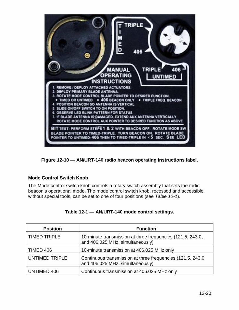
Operating guidance for the radio beacon is provided on the operating instructions label (Figure 12-10) attached to the unit. The radio beacon functions best when the antenna is in a vertical position. The radio beacon has controls that provide visual indicators that are visible to the unaided eye in all light levels, from bright sunlight to total darkness. The controls and visual indicators are optimized for operational ease, especially during times of personal stress or injury.
12-20
Figure 12-10 — AN/URT-140 radio beacon operating instructions label.
Mode Control Switch Knob
The Mode control switch knob controls a rotary switch assembly that sets the radio beacon’s operational mode. The mode control switch knob, recessed and accessible without special tools, can be set to one of four positions (see Table 12-1).
Table 12-1 — AN/URT-140 mode control settings.
Position Function
TIMED TRIPLE 10-minute transmission at three frequencies (121.5, 243.0, and 406.025 MHz, simultaneously)
TIMED 406 10-minute transmission at 406.025 MHz only
UNTIMED TRIPLE Continuous transmission at three frequencies (121.5, 243.0 and 406.025 MHz, simultaneously)
UNTIMED 406 Continuous transmission at 406.025 MHz only

12-21
LED Indicator
The operational status of the radio beacon is indicated by the LED’s blink patterns. As shown on the LED indicator label (Figure 12-11), the indication is based on the unit’s mode of operation. During maintenance BIT mode, blink patterns indicate the progress and result of the test.
Figure 12-11 — AN/URT-140 radio beacon LED indicator label.
Mechanical/Magnetic Activation
The radio beacon set is designed for automatic activation by a mechanical actuator device or when a magnetic plug actuator is removed. The automatic activation state means the unit is ready for operation and will be activated once the actuator is deployed or the plug is removed.

12-22
Power-up BIT
A power-up BIT is initiated each time the ON/OFF switch is slid from OFF to ON. This test verifies that the processor can read and write from its memory and that basic processor communications with its peripherals is working. This test takes less than two seconds, during which time the LED indicator is ON. If the BIT passes, the LED indicator turns OFF for approximately one second before the selected mode of operation begins. If the BIT fails, the LED indicator remains ON.
Maintenance BIT
The maintenance BIT verifies the following three conditions:
1. That battery voltage is above threshold under full load 2. That output power of all three beacons is within tolerance limits 3. All synthesizers are locked
During the maintenance BIT, a special test message is transmitted once on the COSPAS-SARSAT channel 406.025 MHz. This message is recognized by the COSPAS-SARSAT system as a test message and therefore is not responded to by any SAR forces. A COSPAS-SARSAT Beacon Tester can be used to detect the message. Because COSPAS-SARSAT international regulations require that test messages be transmitted 50 seconds after the unit is placed in the maintenance BIT mode, this test lasts approximately 51 seconds.
Inspections
For the latest inspection requirements, see NAVAIR 16-30URT140-1.

12-23
END OF CHAPTER 12
SURVIVAL RADIOS AND BEACONS
REVIEW QUESTIONS 12-1. Which of the following frequencies is designated for voice transmissions of
military emergencies?
A. 121.5 MHz B. 243.0 MHz C. 282.8 MHz D. 406.0 MHz
12-2. What is the rated initial acquisition time of the PRC-149 radio's embedded GPS
receiver?
A. Less than 45 seconds B. Greater than 45 seconds C. Less than 130 seconds D. Greater than 130 seconds
12-3. What is the optimal distance for the PRC-149 microphone to be held from the
user's face?
A. 1 to 3 inches B. 3 to 5 inches C. 6 to 12 inches D. 6 to 18 inches
12-4. What two types of built-in tests are used by the PRC-149 radio?
A. Power-up and Continuous BIT B. Power-up and Maintenance BIT C. Periodic and Continuous BIT D. Periodic and Maintenance BIT
12-5. What is the status of the PRC-149 radio LEDs during power-up BIT?
A. All four LEDs are illuminated B. All four LEDs are extinguished C. The GPS and BCN LEDs illuminate alternately D. The LEDs illuminate sequentially from GPS to BCN
12-6. What indicates that a PRC-149 power-up BIT has failed?
A. All four LEDs are extinguished B. All four LEDs remain illuminated continuously C. The GPS and BCN LEDs illuminate alternately D. The LEDs illuminate sequentially from GPS to BCN
12-24
12-7. Which of the following is NOT a designated CSEL segment?
A. User B. Ground C. Airborne D. Over-The-Horizon
12-8. What PRQ-7 component maintains the volatile memory during PRQ-7 battery
pack changes?
A. Inductor B. Resistor C. Capacitor D. Transistor
12-9. What PRQ-7 radio feature permits the user to purge the memory of crypto keys?
A. Zeroize B. Traffic Encryption Key C. Immediate Auto-Sequence D. Low Probability of Exploitation
12-10. How does a user turn OFF the PRQ-7 radio?
A. Pressing and holding down the power key B. Pressing the power and IMM keys simultaneously C. Pressing any three keys on the keypad and the PTT key D. From the main menu, using the cursor keys to navigate to the power down
command 12-11. How many unsuccessful password entries will cause the PRQ-7 radio to perform
a zeroization?
A. One B. Two C. Three D. Four
12-12. How often is the PRQ-7 radio required to have a link quality check performed?
A. Daily B. Weekly C. Monthly D. Annually

12-25
12-13. The URT-140 beacon functions best when its antenna is positioned in what direction?
A. Inverted B. Vertically C. Horizontally D. Pointed in the direction of transmission