Chapter 1 Routine maintenance and servicing
18
1 Chapter 1 Routine maintenance and servicing Air cleaner element renewal . . . . . . . . . . . . . . . . . . . . . . . . . . . . . . . .31 Air cleaner temperature control check . . . . . . . . . . . . . . . . . . . . . . . .29 Auxiliary drivebelt check . . . . . . . . . . . . . . . . . . . . . . . . . . . . . . . . . . .20 Battery electrolyte level check . . . . . . . . . . . . . . .see “Weekly checks” Battery terminal check . . . . . . . . . . . . . . . . . . . . . . . . . . . . . . . . . . . .17 Brake hydraulic fluid renewal . . . . . . . . . . . . . . . . . . . . . . . . . . . . . . .33 Brake hydraulic system seal and hose renewal . . . . . . . . . . . . . . . . .32 Brake pipe and hose check . . . . . . . . . . . . . . . . . . . . . . . . . . . . . . . .26 Choke adjustment check . . . . . . . . . . . . . . . . . . . . . . . . . . . . . . . . . . .9 Contact breaker point renewal and distributor lubrication - OHV engines . . . . . . . . . . . . . . . . . . . . . . . . . . . . . . . . . . . . . . . . .23 Crankcase ventilation system check . . . . . . . . . . . . . . . . . . . . . . . . .28 Emission control filter element renewal - CVH engines . . . . . . . . . . .30 Engine coolant renewal . . . . . . . . . . . . . . . . . . . . . . . . . . . . . . . . . . .36 Engine idle speed check . . . . . . . . . . . . . . . . . . . . . . . . . . . . . . . . . . .10 Engine oil and filter renewal . . . . . . . . . . . . . . . . . . . . . . . . . . . . . . . . .3 Engine valve clearance check - OHV engines . . . . . . . . . . . . . . . . . .18 Exhaust system check . . . . . . . . . . . . . . . . . . . . . . . . . . . . . . . . . . . . .7 Fluid leak check . . . . . . . . . . . . . . . . . . . . . . . . . . . . . . . . . . . . . . . . . .5 Fluid level checks . . . . . . . . . . . . . . . . . . . . . . . . .see “Weekly checks” Front and rear brake pad/shoe check . . . . . . . . . . . . . . . . . . . . . . . . .4 Front wheel alignment check . . . . . . . . . . . . . . . . . . . . . . . . . . . . . . .35 Gearbox oil level check . . . . . . . . . . . . . . . . . . . . . . . . . . . . . . . . . . .22 Handbrake check . . . . . . . . . . . . . . . . . . . . . . . . . . . . . . . . . . . . . . . .19 Hinge and lock check and lubrication . . . . . . . . . . . . . . . . . . . . . . . .14 HT lead, distributor cap and ignition circuit check . . . . . . . . . . . . . . .13 Ignition timing and contact breaker gap (dwell angle) check - OHV engines . . . . . . . . . . . . . . . . . . . . . . . . . . . . . . . . . . . . . . . .15 Intensive maintenance . . . . . . . . . . . . . . . . . . . . . . . . . . . . . . . . . . . . .2 Introduction . . . . . . . . . . . . . . . . . . . . . . . . . . . . . . . . . . . . . . . . . . . . .1 Mixture adjustment check . . . . . . . . . . . . . . . . . . . . . . . . . . . . . . . . .11 Road test . . . . . . . . . . . . . . . . . . . . . . . . . . . . . . . . . . . . . . . . . . . . . .27 Roadwheel security check . . . . . . . . . . . . . . . . . . . . . . . . . . . . . . . . . .8 Seat belt check . . . . . . . . . . . . . . . . . . . . . . . . . . . . . . . . . . . . . . . . . . .6 Spark plug check . . . . . . . . . . . . . . . . . . . . . . . . . . . . . . . . . . . . . . . .12 Spark plug renewal . . . . . . . . . . . . . . . . . . . . . . . . . . . . . . . . . . . . . . .21 Steering and suspension security check . . . . . . . . . . . . . . . . . . . . . .24 Throttle damper operation check . . . . . . . . . . . . . . . . . . . . . . . . . . . .16 Timing belt renewal - CVH engines . . . . . . . . . . . . . . . . . . . . . . . . . .34 Tyre checks . . . . . . . . . . . . . . . . . . . . . . . . . . . . . .see “Weekly checks” Underbody inspection . . . . . . . . . . . . . . . . . . . . . . . . . . . . . . . . . . . .25 Wiper blade check . . . . . . . . . . . . . . . . . . . . . . . .see “Weekly checks” 1•1 Contents Easy, suitable for novice with little experience Fairly easy, suitable for beginner with some experience Fairly difficult, suitable for competent DIY mechanic Difficult, suitable for experienced DIY mechanic Very difficult, suitable for expert DIY or professional Degrees of difficulty 5 4 3 2 1 Servicing Specifications Lubricants and fluids See end of “Weekly checks” Capacities Engine oil With filter: 1.0 and 1.1 OHV . . . . . . . . . . . . . . . . . . . . . . . . . . . . . . . . . . . . . . . . . 3.25 litres (5.7 Imp pints) 1.3,1.4 and 1.6 CVH . . . . . . . . . . . . . . . . . . . . . . . . . . . . . . . . . . . . . . 3.50 litres (6.2 Imp pints) Without filter: 1.0 and 1.1 OHV . . . . . . . . . . . . . . . . . . . . . . . . . . . . . . . . . . . . . . . . . 2.75 litres (4.8 Imp pints) 1.3, 1.4 and 1.6 CVH . . . . . . . . . . . . . . . . . . . . . . . . . . . . . . . . . . . . . . 3.25 litres (5.7 Imp pints) Cooling system (including heater) 1.0 and 1.1 OHV . . . . . . . . . . . . . . . . . . . . . . . . . . . . . . . . . . . . . . . . . . . 5.5 litres (9.7 Imp pints) 1.3 and 1.4 CVH . . . . . . . . . . . . . . . . . . . . . . . . . . . . . . . . . . . . . . . . . . . 6.3 litres (11.1 Imp pints) 1.6 CVH . . . . . . . . . . . . . . . . . . . . . . . . . . . . . . . . . . . . . . . . . . . . . . . . . 8.0 litres (14.1 Imp pints) Fuel tank All models - pre 1985, except XR2 . . . . . . . . . . . . . . . . . . . . . . . . . . . . . 34 litres (7.5 gallons) XR2 . . . . . . . . . . . . . . . . . . . . . . . . . . . . . . . . . . . . . . . . . . . . . . . . . . . . . 38 litres (8.4 gallons) All models - 1985 on . . . . . . . . . . . . . . . . . . . . . . . . . . . . . . . . . . . . . . . . 40 litres (8.8 gallons) Gearbox 4-speed . . . . . . . . . . . . . . . . . . . . . . . . . . . . . . . . . . . . . . . . . . . . . . . . . . 2.8 litres (4.9 Imp pints) 5-speed . . . . . . . . . . . . . . . . . . . . . . . . . . . . . . . . . . . . . . . . . . . . . . . . . . 3.1 litres (5.5 Imp pints)
Transcript of Chapter 1 Routine maintenance and servicing

1
Chapter 1Routine maintenance and servicing
Air cleaner element renewal . . . . . . . . . . . . . . . . . . . . . . . . . . . . . . . .31Air cleaner temperature control check . . . . . . . . . . . . . . . . . . . . . . . .29Auxiliary drivebelt check . . . . . . . . . . . . . . . . . . . . . . . . . . . . . . . . . . .20Battery electrolyte level check . . . . . . . . . . . . . . .see “Weekly checks”Battery terminal check . . . . . . . . . . . . . . . . . . . . . . . . . . . . . . . . . . . .17Brake hydraulic fluid renewal . . . . . . . . . . . . . . . . . . . . . . . . . . . . . . .33Brake hydraulic system seal and hose renewal . . . . . . . . . . . . . . . . .32Brake pipe and hose check . . . . . . . . . . . . . . . . . . . . . . . . . . . . . . . .26Choke adjustment check . . . . . . . . . . . . . . . . . . . . . . . . . . . . . . . . . . .9Contact breaker point renewal and distributor lubrication
- OHV engines . . . . . . . . . . . . . . . . . . . . . . . . . . . . . . . . . . . . . . . . .23Crankcase ventilation system check . . . . . . . . . . . . . . . . . . . . . . . . .28Emission control filter element renewal - CVH engines . . . . . . . . . . .30Engine coolant renewal . . . . . . . . . . . . . . . . . . . . . . . . . . . . . . . . . . .36Engine idle speed check . . . . . . . . . . . . . . . . . . . . . . . . . . . . . . . . . . .10Engine oil and filter renewal . . . . . . . . . . . . . . . . . . . . . . . . . . . . . . . . .3Engine valve clearance check - OHV engines . . . . . . . . . . . . . . . . . .18Exhaust system check . . . . . . . . . . . . . . . . . . . . . . . . . . . . . . . . . . . . .7Fluid leak check . . . . . . . . . . . . . . . . . . . . . . . . . . . . . . . . . . . . . . . . . .5Fluid level checks . . . . . . . . . . . . . . . . . . . . . . . . .see “Weekly checks”Front and rear brake pad/shoe check . . . . . . . . . . . . . . . . . . . . . . . . .4
Front wheel alignment check . . . . . . . . . . . . . . . . . . . . . . . . . . . . . . .35Gearbox oil level check . . . . . . . . . . . . . . . . . . . . . . . . . . . . . . . . . . .22Handbrake check . . . . . . . . . . . . . . . . . . . . . . . . . . . . . . . . . . . . . . . .19Hinge and lock check and lubrication . . . . . . . . . . . . . . . . . . . . . . . .14HT lead, distributor cap and ignition circuit check . . . . . . . . . . . . . . .13Ignition timing and contact breaker gap (dwell angle) check
- OHV engines . . . . . . . . . . . . . . . . . . . . . . . . . . . . . . . . . . . . . . . .15Intensive maintenance . . . . . . . . . . . . . . . . . . . . . . . . . . . . . . . . . . . . .2Introduction . . . . . . . . . . . . . . . . . . . . . . . . . . . . . . . . . . . . . . . . . . . . .1Mixture adjustment check . . . . . . . . . . . . . . . . . . . . . . . . . . . . . . . . .11Road test . . . . . . . . . . . . . . . . . . . . . . . . . . . . . . . . . . . . . . . . . . . . . .27Roadwheel security check . . . . . . . . . . . . . . . . . . . . . . . . . . . . . . . . . .8Seat belt check . . . . . . . . . . . . . . . . . . . . . . . . . . . . . . . . . . . . . . . . . . .6Spark plug check . . . . . . . . . . . . . . . . . . . . . . . . . . . . . . . . . . . . . . . .12Spark plug renewal . . . . . . . . . . . . . . . . . . . . . . . . . . . . . . . . . . . . . . .21Steering and suspension security check . . . . . . . . . . . . . . . . . . . . . .24Throttle damper operation check . . . . . . . . . . . . . . . . . . . . . . . . . . . .16Timing belt renewal - CVH engines . . . . . . . . . . . . . . . . . . . . . . . . . .34Tyre checks . . . . . . . . . . . . . . . . . . . . . . . . . . . . . .see “Weekly checks”Underbody inspection . . . . . . . . . . . . . . . . . . . . . . . . . . . . . . . . . . . .25Wiper blade check . . . . . . . . . . . . . . . . . . . . . . . .see “Weekly checks”
1•1
Contents
Easy, suitable fornovice with littleexperience
Fairly easy, suitablefor beginner withsome experience
Fairly difficult,suitable for competentDIY mechanic
Difficult, suitable forexperienced DIYmechanic
Very difficult,suitable for expert DIYor professional
Degrees of difficulty
54321Servicing SpecificationsLubricants and fluids See end of “Weekly checks”
CapacitiesEngine oilWith filter:
1.0 and 1.1 OHV . . . . . . . . . . . . . . . . . . . . . . . . . . . . . . . . . . . . . . . . . 3.25 litres (5.7 Imp pints)1.3,1.4 and 1.6 CVH . . . . . . . . . . . . . . . . . . . . . . . . . . . . . . . . . . . . . . 3.50 litres (6.2 Imp pints)
Without filter:1.0 and 1.1 OHV . . . . . . . . . . . . . . . . . . . . . . . . . . . . . . . . . . . . . . . . . 2.75 litres (4.8 Imp pints)1.3, 1.4 and 1.6 CVH . . . . . . . . . . . . . . . . . . . . . . . . . . . . . . . . . . . . . . 3.25 litres (5.7 Imp pints)
Cooling system (including heater)1.0 and 1.1 OHV . . . . . . . . . . . . . . . . . . . . . . . . . . . . . . . . . . . . . . . . . . . 5.5 litres (9.7 Imp pints)1.3 and 1.4 CVH . . . . . . . . . . . . . . . . . . . . . . . . . . . . . . . . . . . . . . . . . . . 6.3 litres (11.1 Imp pints)1.6 CVH . . . . . . . . . . . . . . . . . . . . . . . . . . . . . . . . . . . . . . . . . . . . . . . . . 8.0 litres (14.1 Imp pints)
Fuel tankAll models - pre 1985, except XR2 . . . . . . . . . . . . . . . . . . . . . . . . . . . . . 34 litres (7.5 gallons)XR2 . . . . . . . . . . . . . . . . . . . . . . . . . . . . . . . . . . . . . . . . . . . . . . . . . . . . . 38 litres (8.4 gallons)All models - 1985 on . . . . . . . . . . . . . . . . . . . . . . . . . . . . . . . . . . . . . . . . 40 litres (8.8 gallons)
Gearbox4-speed . . . . . . . . . . . . . . . . . . . . . . . . . . . . . . . . . . . . . . . . . . . . . . . . . . 2.8 litres (4.9 Imp pints)5-speed . . . . . . . . . . . . . . . . . . . . . . . . . . . . . . . . . . . . . . . . . . . . . . . . . . 3.1 litres (5.5 Imp pints)

1•2 Servicing SpecificationsEngineOil filter type . . . . . . . . . . . . . . . . . . . . . . . . . . . . . . . . . . . . . . . . . . . . . . Champion C104Valve clearances (only OHV applicable):
Inlet:At operating temperature . . . . . . . . . . . . . . . . . . . . . . . . . . . . . . . . 0.22 mm (0.009 in)Cold . . . . . . . . . . . . . . . . . . . . . . . . . . . . . . . . . . . . . . . . . . . . . . . . . 0.20 to 0.25 mm (0.008 to 0.010 in)
Exhaust:At operating temperature . . . . . . . . . . . . . . . . . . . . . . . . . . . . . . . . 0.59 mm (0.023 in)Cold . . . . . . . . . . . . . . . . . . . . . . . . . . . . . . . . . . . . . . . . . . . . . . . . . 0.56 to 0.61 mm (0.022 to 0.024 in)
Cooling systemDrivebelt tension . . . . . . . . . . . . . . . . . . . . . . . . . . . . . . . . . . . . . . . . . . 4.0 mm (0.16 in) total deflection at the midpoint of the belt’s longest run
Fuel systemAir filter element type:
1.0 and 1.1 (OHV) . . . . . . . . . . . . . . . . . . . . . . . . . . . . . . . . . . . . . . . . Champion W1531.3 (CVH) . . . . . . . . . . . . . . . . . . . . . . . . . . . . . . . . . . . . . . . . . . . . . . . Champion W1271.4 (CVH) . . . . . . . . . . . . . . . . . . . . . . . . . . . . . . . . . . . . . . . . . . . . . . . Champion W1791.6 (CVH) . . . . . . . . . . . . . . . . . . . . . . . . . . . . . . . . . . . . . . . . . . . . . . . Champion W201
Ignition systemSpark plugs:
Make and type:Mechanical system . . . . . . . . . . . . . . . . . . . . . . . . . . . . . . . . . . . . . Champion RS9YCC or RS9YCElectronic system . . . . . . . . . . . . . . . . . . . . . . . . . . . . . . . . . . . . . . Champion RC7YCC or RC7YC
Electrode gap:RS9YCC and RC7YCC . . . . . . . . . . . . . . . . . . . . . . . . . . . . . . . . . . 0.80 mm (0.032 in)RS9YC and RC7YC . . . . . . . . . . . . . . . . . . . . . . . . . . . . . . . . . . . . 0.75 mm (0.030 in)
Note: The spark plug gap quoted is that recommended by Champion for their specified plugs listed above. If spark plugs of any other type are tobe fitted, refer to their manufacturer’s recommendations.Contact breaker points gap . . . . . . . . . . . . . . . . . . . . . . . . . . . . . . . . . . 0.40 to 0.50 mm (0.016 to 0.020 in)Dwell (mechanical ignition):
Angle . . . . . . . . . . . . . . . . . . . . . . . . . . . . . . . . . . . . . . . . . . . . . . . . . . 48° to 52°Variation (from idle to 2000 rpm) . . . . . . . . . . . . . . . . . . . . . . . . . . . . 4° maximumOverlap (lobe-to-lobe variation) . . . . . . . . . . . . . . . . . . . . . . . . . . . . . 3° maximum
Timing (initial):1.0 litre OHV (pre 1986) . . . . . . . . . . . . . . . . . . . . . . . . . . . . . . . . . . . . 12° BTDC1.1 litre OHV (pre 1986) . . . . . . . . . . . . . . . . . . . . . . . . . . . . . . . . . . . . 6° BTDC
Ignition HT lead set:Resistance . . . . . . . . . . . . . . . . . . . . . . . . . . . . . . . . . . . . . . . . . . . . . 30 k ohms maximum per leadType:
Mechanical system . . . . . . . . . . . . . . . . . . . . . . . . . . . . . . . . . . . . . Champion CLS 8 boxed setElectronic system . . . . . . . . . . . . . . . . . . . . . . . . . . . . . . . . . . . . . . Champion CLS 9 boxed set
BrakesFront brake pad friction material minimum thickness . . . . . . . . . . . . . . 1.5 mm (0.059 in)Rear brake shoe friction material minimum thickness . . . . . . . . . . . . . . 1.0 mm (0.04 in)
TyresTyre sizes:Note: Manufacturers often modify tyre sizes and pressure recommendations. The following is intended as a guide only. Refer to your vehiclehandbook or a Ford dealer for the latest recommendations.
XR2 . . . . . . . . . . . . . . . . . . . . . . . . . . . . . . . . . . . . . . . . . . . . . . . . . . . 185/60 HR 13Other models . . . . . . . . . . . . . . . . . . . . . . . . . . . . . . . . . . . . . . . . . . . 135 SR 13, 155/70 SR 13 or 165/65 SR 13
Tyre pressures: See end of “Weekly checks”
Torque wrench settings Nm lbf ftEngine oil drain plug . . . . . . . . . . . . . . . . . . . . . . . . . . . . . . . . . . . . . . . 25 18Radiator coolant drain plug . . . . . . . . . . . . . . . . . . . . . . . . . . . . . . . . . . 1.5 1.1Gearbox oil filler/level plug . . . . . . . . . . . . . . . . . . . . . . . . . . . . . . . . . . 27 20Roadwheel bolts . . . . . . . . . . . . . . . . . . . . . . . . . . . . . . . . . . . . . . . . . . 100 74Spark plugs:
OHV engines . . . . . . . . . . . . . . . . . . . . . . . . . . . . . . . . . . . . . . . . . . . . 13 to 20 10 to 15CVH engines . . . . . . . . . . . . . . . . . . . . . . . . . . . . . . . . . . . . . . . . . . . . 27 20
Brake caliper piston housing bolts . . . . . . . . . . . . . . . . . . . . . . . . . . . . 23 17
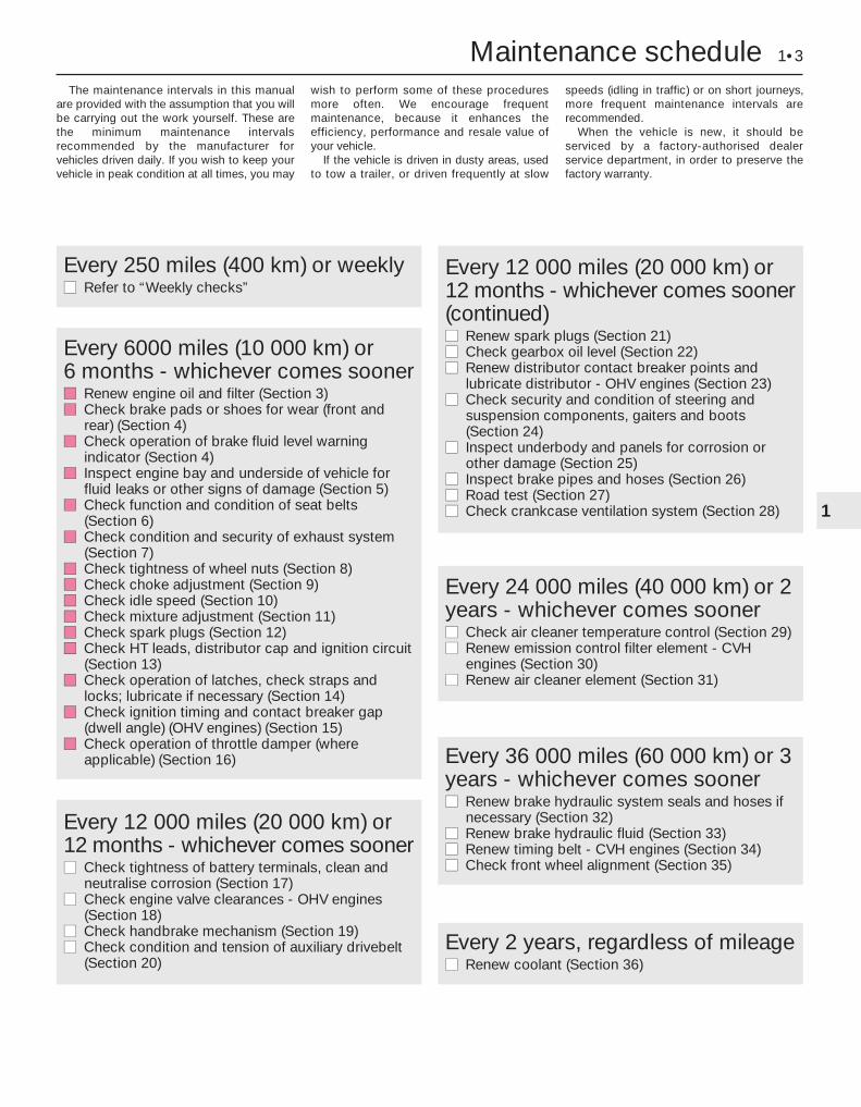
The maintenance intervals in this manualare provided with the assumption that you willbe carrying out the work yourself. These arethe minimum maintenance intervalsrecommended by the manufacturer forvehicles driven daily. If you wish to keep yourvehicle in peak condition at all times, you may
wish to perform some of these proceduresmore often. We encourage frequentmaintenance, because it enhances theefficiency, performance and resale value ofyour vehicle.
If the vehicle is driven in dusty areas, usedto tow a trailer, or driven frequently at slow
speeds (idling in traffic) or on short journeys,more frequent maintenance intervals arerecommended.
When the vehicle is new, it should beserviced by a factory-authorised dealerservice department, in order to preserve thefactory warranty.
Maintenance schedule 1•3
1
Every 250 miles (400 km) or weeklymm Refer to “Weekly checks”
Every 6000 miles (10 000 km) or 6 months - whichever comes soonermm Renew engine oil and filter (Section 3) mm Check brake pads or shoes for wear (front and
rear) (Section 4) mm Check operation of brake fluid level warning
indicator (Section 4) mm Inspect engine bay and underside of vehicle for
fluid leaks or other signs of damage (Section 5) mm Check function and condition of seat belts
(Section 6)mm Check condition and security of exhaust system
(Section 7)mm Check tightness of wheel nuts (Section 8)mm Check choke adjustment (Section 9)mm Check idle speed (Section 10) mm Check mixture adjustment (Section 11) mm Check spark plugs (Section 12)mm Check HT leads, distributor cap and ignition circuit
(Section 13) mm Check operation of latches, check straps and
locks; lubricate if necessary (Section 14)mm Check ignition timing and contact breaker gap
(dwell angle) (OHV engines) (Section 15) mm Check operation of throttle damper (where
applicable) (Section 16)
Every 12 000 miles (20 000 km) or12 months - whichever comes sooner(continued)mm Renew spark plugs (Section 21) mm Check gearbox oil level (Section 22) mm Renew distributor contact breaker points and
lubricate distributor - OHV engines (Section 23)mm Check security and condition of steering and
suspension components, gaiters and boots(Section 24)
mm Inspect underbody and panels for corrosion orother damage (Section 25)
mm Inspect brake pipes and hoses (Section 26) mm Road test (Section 27)mm Check crankcase ventilation system (Section 28)
Every 24 000 miles (40 000 km) or 2years - whichever comes soonermm Check air cleaner temperature control (Section 29)mm Renew emission control filter element - CVH
engines (Section 30)mm Renew air cleaner element (Section 31)
Every 36 000 miles (60 000 km) or 3years - whichever comes soonermm Renew brake hydraulic system seals and hoses if
necessary (Section 32) mm Renew brake hydraulic fluid (Section 33) mm Renew timing belt - CVH engines (Section 34)mm Check front wheel alignment (Section 35)
Every 12 000 miles (20 000 km) or12 months - whichever comes soonermm Check tightness of battery terminals, clean and
neutralise corrosion (Section 17) mm Check engine valve clearances - OHV engines
(Section 18) mm Check handbrake mechanism (Section 19) mm Check condition and tension of auxiliary drivebelt
(Section 20) Every 2 years, regardless of mileagemm Renew coolant (Section 36)
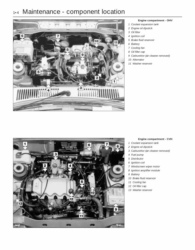
1•4 Maintenance - component locationEngine compartment - OHV
1 Coolant expansion tank
2 Engine oil dipstick
3 Oil filter
4 Ignition coil
5 Brake fluid reservoir
6 Battery
7 Cooling fan
8 Oil filler cap
9 Carburettor (air cleaner removed)
10 Alternator
11 Washer reservoir
Engine compartment - CVH
1 Coolant expansion tank
2 Engine oil dipstick
3 Carburettor (air cleaner removed)
4 Fuel pump
5 Distributor
6 Ignition coil
7 Windscreen wiper motor
8 Ignition amplifier module
9 Battery
10 Brake fluid reservoir
11 Cooling fan
12 Oil filler cap
13 Washer reservoir
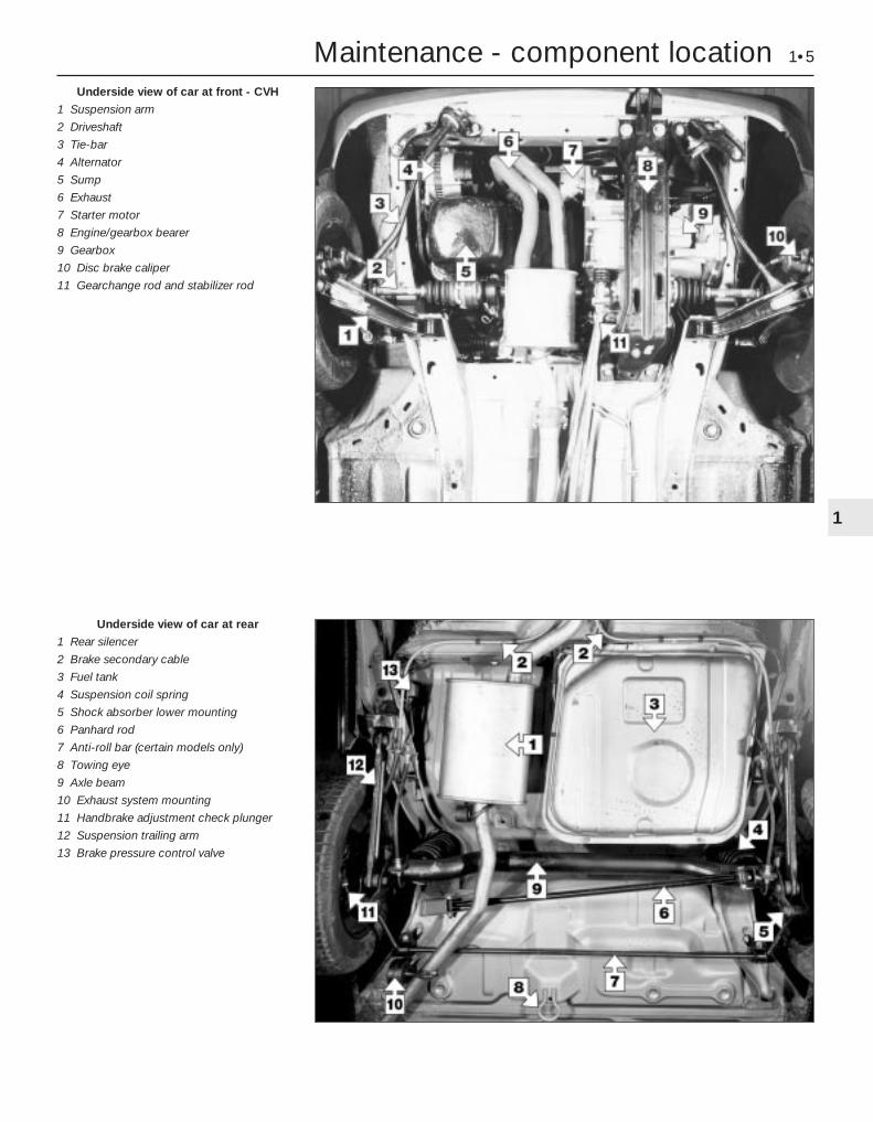
Maintenance - component location 1•5
1
Underside view of car at rear
1 Rear silencer
2 Brake secondary cable
3 Fuel tank
4 Suspension coil spring
5 Shock absorber lower mounting
6 Panhard rod
7 Anti-roll bar (certain models only)
8 Towing eye
9 Axle beam
10 Exhaust system mounting
11 Handbrake adjustment check plunger
12 Suspension trailing arm
13 Brake pressure control valve
Underside view of car at front - CVH
1 Suspension arm
2 Driveshaft
3 Tie-bar
4 Alternator
5 Sump
6 Exhaust
7 Starter motor
8 Engine/gearbox bearer
9 Gearbox
10 Disc brake caliper
11 Gearchange rod and stabilizer rod
1 Introduction
This Chapter is designed to help the homemechanic maintain his/her vehicle for safety,economy, long life and peak performance.
The Chapter contains a mastermaintenance schedule, followed by Sectionsdealing specifically with each task in theschedule. Visual checks, adjustments,component renewal and other helpful itemsare included. Refer to the accompanyingillustrations of the engine compartment andthe underside of the vehicle for the locationsof the various components.
Servicing your vehicle in accordance withthe mileage/time maintenance schedule andthe following Sections will provide a plannedmaintenance programme, which should resultin a long and reliable service life. This is acomprehensive plan, so maintaining someitems but not others at the specified serviceintervals, will not produce the same results.
As you service your vehicle, you willdiscover that many of the procedures can -and should - be grouped together, because ofthe particular procedure being performed, orbecause of the close proximity of twootherwise-unrelated components to oneanother. For example, if the vehicle is raisedfor any reason, the exhaust can be inspectedat the same time as the suspension andsteering components.
The first step in this maintenanceprogramme is to prepare yourself before theactual work begins. Read through all theSections relevant to the work to be carriedout, then make a list and gather together allthe parts and tools required. If a problem isencountered, seek advice from a partsspecialist, or a dealer service department.
2 Intensive maintenance
If, from the time the vehicle is new, theroutine maintenance schedule is followedclosely, and frequent checks are made of fluidlevels and high-wear items, as suggestedthroughout this manual, the engine will bekept in relatively good running condition, andthe need for additional work will be minimised.
It is possible that there will be times whenthe engine is running poorly due to the lack ofregular maintenance. This is even more likelyif a used vehicle, which has not receivedregular and frequent maintenance checks, ispurchased. In such cases, additional workmay need to be carried out, outside of theregular maintenance intervals.
If engine wear is suspected, a compressiontest will provide valuable informationregarding the overall performance of the maininternal components. Such a test can be usedas a basis to decide on the extent of the workto be carried out. If, for example, acompression test indicates serious internal
engine wear, conventional maintenance asdescribed in this Chapter will not greatlyimprove the performance of the engine, andmay prove a waste of time and money, unlessextensive overhaul work is carried out first.
The following series of operations are thosemost often required to improve theperformance of a generally poor-runningengine:
Primary operationsa) Clean, inspect and test the batteryb) Check all the engine-related fluidsc) Check the condition and tension of the
auxiliary drivebeltd) Renew the spark plugse) Inspect the distributor cap and HT leads -
as applicablef) Check the condition of the air cleaner
filter element, and renew if necessaryg) Renew the fuel filter (if fitted)h) Check the condition of all hoses, and
check for fluid leaksi) Check the idle speed and mixture settings
- as applicableIf the above operations do not prove fully
effective, carry out the following secondaryoperations:
Secondary operationsa) Check the charging systemb) Check the ignition systemc) Check the fuel systemd) Renew the distributor cap and rotor arm -
as applicablee) Renew the ignition HT leads - as applicable
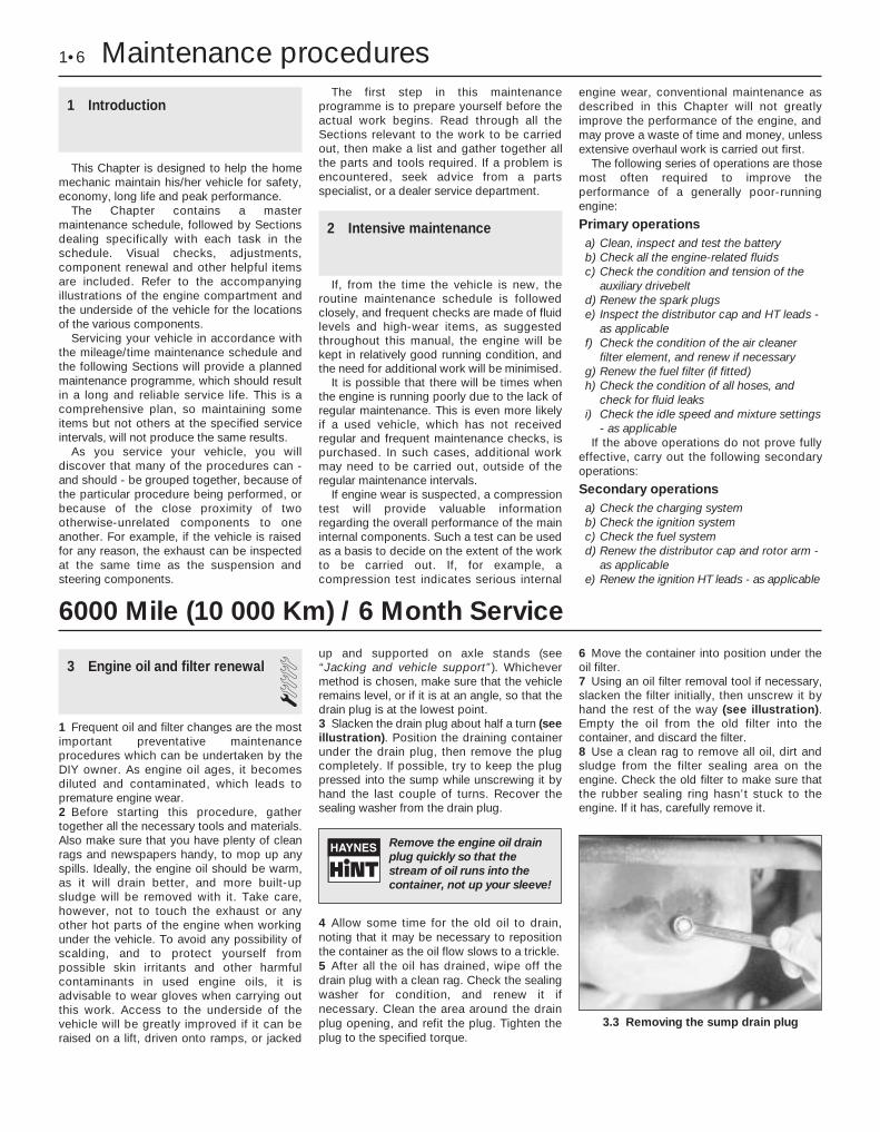
3 Engine oil and filter renewal 11 Frequent oil and filter changes are the mostimportant preventative maintenanceprocedures which can be undertaken by theDIY owner. As engine oil ages, it becomesdiluted and contaminated, which leads topremature engine wear.2 Before starting this procedure, gathertogether all the necessary tools and materials.Also make sure that you have plenty of cleanrags and newspapers handy, to mop up anyspills. Ideally, the engine oil should be warm,as it will drain better, and more built-upsludge will be removed with it. Take care,however, not to touch the exhaust or anyother hot parts of the engine when workingunder the vehicle. To avoid any possibility ofscalding, and to protect yourself frompossible skin irritants and other harmfulcontaminants in used engine oils, it isadvisable to wear gloves when carrying outthis work. Access to the underside of thevehicle will be greatly improved if it can beraised on a lift, driven onto ramps, or jacked
up and supported on axle stands (see“Jacking and vehicle support”). Whichevermethod is chosen, make sure that the vehicleremains level, or if it is at an angle, so that thedrain plug is at the lowest point.3 Slacken the drain plug about half a turn (seeillustration). Position the draining containerunder the drain plug, then remove the plugcompletely. If possible, try to keep the plugpressed into the sump while unscrewing it byhand the last couple of turns. Recover thesealing washer from the drain plug.
4 Allow some time for the old oil to drain,noting that it may be necessary to repositionthe container as the oil flow slows to a trickle.5 After all the oil has drained, wipe off thedrain plug with a clean rag. Check the sealingwasher for condition, and renew it ifnecessary. Clean the area around the drainplug opening, and refit the plug. Tighten theplug to the specified torque.
6 Move the container into position under theoil filter.7 Using an oil filter removal tool if necessary,slacken the filter initially, then unscrew it byhand the rest of the way (see illustration).Empty the oil from the old filter into thecontainer, and discard the filter.8 Use a clean rag to remove all oil, dirt andsludge from the filter sealing area on theengine. Check the old filter to make sure thatthe rubber sealing ring hasn’t stuck to theengine. If it has, carefully remove it.
1•6 Maintenance procedures
3.3 Removing the sump drain plug
6000 Mile (10 000 Km) / 6 Month Service
Remove the engine oil drainplug quickly so that thestream of oil runs into thecontainer, not up your sleeve!

9 Apply a light coating of clean engine oil tothe sealing ring on the new filter, then screw itinto position on the engine. Tighten the filterfirmly by hand only - do not use any tools.Wipe clean the filter and sump drain plug.10 Remove the old oil and all tools fromunder the car, then lower the car to theground (if applicable).11 Remove the oil filler cap and withdraw thedipstick. Fill the engine, using the correctgrade and type of oil (see “Lubricants andfluids” and “Capacities” in the Specifications).An oil can spout or funnel may help to reducespillage. Pour in half the specified quantity ofoil first, then wait a few minutes for the oil tofall to the sump. Continue adding oil a smallquantity at a time until the level is up to thelower mark on the dipstick. Finally, bring thelevel up to the upper mark on the dipstick.Insert the dipstick, and refit the filler cap.
12 Start the engine and run it for a fewminutes; check for leaks around the oil filterseal and the sump drain plug. Note that theremay be a delay of a few seconds before the oilpressure warning light goes out when theengine is first started, as the oil circulatesthrough the engine oil galleries and the new oilfilter, before the pressure builds up.13 Switch off the engine, and wait a fewminutes for the oil to settle in the sump oncemore. With the new oil circulated and the filtercompletely full, recheck the level on thedipstick, and add more oil as necessary.14 Dispose of the used engine oil safely.
4 Front and rear brakepad/shoe check 1
1 Firmly apply the handbrake, then jack upthe front and rear of the car and support itsecurely on axle stands (see “Jacking andvehicle support”).2 For a quick check, the front brake disc padscan be inspected without removing the frontwheels by inserting a mirror between eachcaliper and roadwheel (see illustrations). Ifany one pad is worn down to the minimumspecified thickness, all four pads (on bothfront wheels) must be renewed.3 For a comprehensive check, the brake discpads should be removed and cleaned. Theoperation of the caliper can then also bechecked, and the condition of the brake discscan be fully examined on both sides. Refer toChapter 9 for further information.
4 The rear brake shoe friction material can beinspected for wear without removing theroadwheels. Working beneath the vehicle,prise the plug from the brake backplate andusing an inspection lamp or torch, check thatthe friction material thickness is not less thanthe minimum given in the Specifications (seeillustrations). If any one of the shoes hasworn below the specified limit, the shoes mustbe renewed as an axle set (4 shoes).5 At the same interval, check the function ofthe brake fluid level warning light. Chock thewheels, release the handbrake and switch onthe ignition. Unscrew and raise the brake fluidreservoir cap whilst an assistant observes thewarning light: it should come on as the levelsensor is withdrawn from the fluid. Refit thecap.6 On completion, refit the wheels and lowerthe car to the ground.
5 Fluid leak check 1
1 Visually inspect the engine joint faces,gaskets and seals for any signs of water or oilleaks. Pay particular attention to the areasaround the rocker cover, cylinder head, oilfilter and sump joint faces. Bear in mind thatover a period of time some very slightseepage from these areas is to be expectedbut what you are really looking for is anyindication of a serious leak. Should a leak befound, renew the offending gasket or oil sealby referring to the appropriate Chapter(s) inthis manual.2 Similarly, check the transmission for oilleaks, and investigate and rectify andproblems found.3 Check the security and condition of all theengine related pipes and hoses. Ensure thatall cable-ties or securing clips are in place andin good condition. Clips which are broken ormissing can lead to chafing of the hoses,pipes or wiring which could cause moreserious problems in the future.4 Carefully check the condition of all coolant,fuel and brake hoses. Renew any hose whichis cracked, swollen or deteriorated. Crackswill show up better if the hose is squeezed.Pay close attention to the hose clips thatsecure the hoses to the system components.Hose clips can pinch and puncture hoses,resulting in leaks. If wire type hose clips areused, it may be a good idea to replace themwith screw-type clips.5 With the vehicle raised, inspect the fueltank and filler neck for punctures, cracks and
Every 6000 miles or 6 months 1•7
4.2b Inspect the disc brake pads throughthe caliper housing aperture
4.4b . . . to check the rear brake linings forwear
4.4a Remove the inspection plug from therear brake backplate . . .
4.2a Using a mirror to check disc brakepads for wear
3.7 Removing the engine oil filter with aclamp wrench
1
Leaks in the cooling systemwill usually show up aswhite or rust-coloureddeposits around the area
adjoining the leak.
other damage. The connection between thefiller neck and tank is especially critical.Sometimes a rubber filler neck or connectinghose will leak due to loose retaining clamps ordeteriorated rubber.6 Similarly, inspect all brake hoses and metalpipes. If any damage or deterioration isdiscovered, do not drive the vehicle until thenecessary repair work has been carried out.Renew any damaged sections of hose or pipe.7 Carefully check all rubber hoses and metalfuel lines leading away from the petrol tank.Check for loose connections, deterioratedhoses, crimped lines and other damage. Payparticular attention to the vent pipes andhoses which often loop up around the fillerneck and can become blocked or crimped.Follow the lines to the front of the vehiclecarefully inspecting them all the way. Renewdamaged sections as necessary.8 From within the engine compartment,check the security of all fuel hose attachmentsand pipe unions, and inspect the fuel hosesand vacuum hoses for kinks, chafing anddeterioration.9 Check the condition of all exposed wiringharnesses.
6 Seat belt check 11 Periodically check the belts for fraying orother damage. If evident, renew the belt.2 If the belts become dirty, wipe them with adamp cloth using a little detergent only.3 Check the tightness of the anchor bolts andif they are ever disconnected, make quite surethat the original sequence of fitting ofwashers, bushes and anchor plates isretained.
7 Exhaust system check 1With the vehicle raised on a hoist or
supported on axle stands (see “Jacking andvehicle support”), check the exhaust systemfor signs of leaks, corrosion or damage andcheck the rubber mountings for condition andsecurity (see illustration). Where damage orcorrosion are evident, renew the systemcomplete or in sections, as applicable, usingthe information given in Chapter 4.
8 Roadwheel security check 1With the wheels on the ground, slacken
each wheel bolt by a quarter turn, thenretighten it immediately to the specifiedtorque.
9 Choke adjustment check 2On models equipped with carburettors of
Ford manufacture, refer to Chapter 4, Section9 and check that the choke is adjusted withinthe stated parameters.
10 Engine idle speed check 3Note: Refer to the precautions given inSection 1 of Chapter 4 before proceeding.Note: Before carrying out any carburettoradjustments, ensure that the ignition timingand spark plug gaps are set as specified. Tocarry out this adjustment, an accuratetachometer will be required.
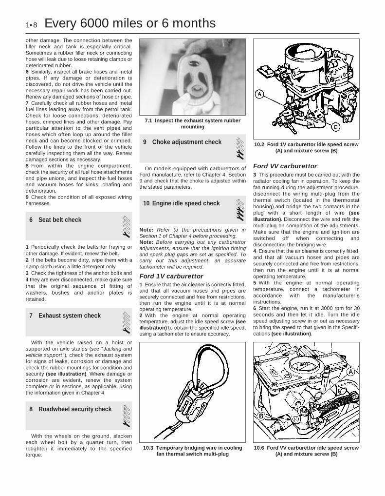
Ford 1V carburettor1 Ensure that the air cleaner is correctly fitted,and that all vacuum hoses and pipes aresecurely connected and free from restrictions,then run the engine until it is at normaloperating temperature.2 With the engine at normal operatingtemperature, adjust the idle speed screw (seeillustration) to obtain the specified idle speed,using a tachometer to ensure accuracy.
Ford VV carburettor3 This procedure must be carried out with theradiator cooling fan in operation. To keep thefan running during the adjustment procedure,disconnect the wiring multi-plug from thethermal switch (located in the thermostathousing) and bridge the two contacts in theplug with a short length of wire (seeillustration). Disconnect the wire and refit themulti-plug on completion of the adjustments.Make sure that the engine and ignition areswitched off when connecting anddisconnecting the bridging wire.4 Ensure that the air cleaner is correctly fitted,and that all vacuum hoses and pipes aresecurely connected and free from restrictions,then run the engine until it is at normaloperating temperature.5 With the engine at normal operatingtemperature, connect a tachometer inaccordance with the manufacturer’sinstructions.6 Start the engine, run it at 3000 rpm for 30seconds and then let it idle. Turn the idlespeed adjusting screw in or out as necessaryto bring the speed to that given in the Specifi-cations (see illustration).
1•8 Every 6000 miles or 6 months
7.1 Inspect the exhaust system rubbermounting
10.3 Temporary bridging wire in coolingfan thermal switch multi-plug
10.6 Ford VV carburettor idle speed screw(A) and mixture screw (B)
10.2 Ford 1V carburettor idle speed screw(A) and mixture screw (B)

Weber 2V carburettor7 Refer to the information relating to the Ford1V carburettor for details, and to theaccompanying illustration (see illustration)for the adjusting screws. Ensure that theengine fan is operating by pulling the twowires from the sensor, and connecting thewires with a jumper lead.
Weber 2V DFTM 8 Before carrying out this adjustment, ensurethat the air cleaner is correctly fitted and thatall vacuum hoses and pipes are securelyconnected and free from restrictions. Run theengine until it is at normal operatingtemperature.9 The cooling fan must be kept runningduring the adjustment procedure. To do this,disconnect the wiring multi-plug from thethermal switch (located in the thermostathousing) and bridge the two contacts in theplug with a short length of wire.10 Start the engine and turn the idle speedadjustment screw (see illustration) to obtainthe specified idle speed, using a tachometerto ensure accuracy.
Weber 2V TLD carburettor 11 Refer to the information relating to theWeber 2V DFTM carburettor for details, and tothe accompanying illustration (see illustration)for the adjusting screws.
Weber (1V) TLM carburettor12 Before carrying out this adjustment,ensure that the air cleaner is correctly fittedand that all vacuum hoses and pipes aresecurely connected and free from restrictions.Run the engine until it is at normal operatingtemperature.13 Connect a reliable tachometer to theengine in accordance with the manufacturer’sinstructions.14 Increase the engine speed to 3000 rpmand hold it at this speed for 30 seconds, thenallow the engine to idle. Adjust the idle speedto within the specified range by turning theidle speed screw (see illustration).
11 Mixture adjustment check 3Note: Refer to the precautions given inSection 1 of Chapter 4 before proceeding.Note: Before carrying out any carburettoradjustments, ensure that the ignition timingand spark plug gaps are set as specified. Tocarry out the adjustments an accuratetachometer and an exhaust gas analyser (COmeter) will be required. Adjustment of the idlemixture setting should not be attempted interritories where this may cause a violation ofexhaust emission regulations. Where theseregulations are less stringent the followingprocedures may be used.
Ford 1V carburettor1 Ensure that the air cleaner is correctly fittedand that all vacuum hoses and pipes aresecurely connected and free from restrictions,then run the engine until it is at normaloperating temperature.2 Using a small screwdriver, prise out thetamperproof plug (if fitted) over the idlemixture screw.3 Connect the CO meter and tachometeraccording to the manufacturer’s instructions.4 Adjust the idle speed to the specified setting.5 Run the engine at 3000 rpm for 30 secondsto clear the inlet manifold of excess fuel.Repeat this operation every 30 secondsduring the adjustment procedure.
6 Turn the idle mixture screw in the desireddirection to achieve the fastest possibleengine speed consistent with smooth, evenrunning or the correct specified CO readingon the meter scale.7 If necessary, readjust the idle speed settingon completion. Fit a new tamperproof plug tothe mixture screw.
Ford VV carburettor8 This procedure must be carried out with theradiator cooling fan in operation. To keep thefan running during the adjustment procedure,disconnect the wiring multi-plug from thethermal switch (located in the thermostathousing) and bridge the two contacts in theplug with a short length of wire. Disconnectthe wire and refit the multi-plug on completionof the adjustments. Make sure that the engineand ignition are switched off when connectingand disconnecting the bridging wire.9 To adjust the mixture accurately, connect aCO (exhaust gas) analyser and a tachometerin accordance with the manufacturer’sinstructions. 10 Ensure that the air cleaner is correctlyfitted and that all vacuum hoses and pipes aresecurely connected and free from restrictions,then run the engine until it is at normaloperating temperature.11 Using a thin, sharp screwdriver, prise outthe tamperproof plug which covers themixture screw.12 Start the engine and run it at 3000 rpm for30 seconds, then allow it to return to idle. Turnthe mixture screw in (weak) or out (rich) untilthe CO level is within the specified range asindicated on the analysing equipment. Theadjustment must be carried out within 30seconds; otherwise, again increase the enginespeed for 30 seconds before continuing withthe adjustment.13 Once the mixture is correct, adjust the idlespeed then recheck the mixture.14 Switch off the engine and remove thetachometer and the exhaust gas analyser. Fita new tamperproof plug to the mixture screw.15 In the absence of a suitable exhaust gasanalyser, an approximate setting of themixture screw may be made by turning thescrew inwards (engine idling) until the idlespeed just begins to drop. Unscrew the screw
Every 6000 miles or 6 months 1•9
10.11 Weber 2V TLD carburettor mixturescrew (A) and idle speed screw (B)
10.14 Weber (1V) TLM carburettor idlespeed screw (A) and mixture screw (B)
10.10 Weber 2V DFTM carburettor mixturescrew (A) and idle speed screw (B)
10.7 Weber 2V carburettor idle speedscrew (A) and mixture screw (B)
1

the smallest amount necessary to achievesmooth idle. The CO level of the exhaust gasshould be checked by your dealer at theearliest opportunity and further adjustmentcarried out as may be necessary.
Weber 2V carburettor16 Refer to the information relating to theFord 1V carburettor for details. Ensure thatthe engine fan is operating by pulling the twowires from the sensor, and connecting thewires with a jumper lead.
Weber 2V DFTM carburettor17 The cooling fan must be kept runningduring the adjustment procedure. To do this,disconnect the wiring multi-plug from thethermal switch (located in the thermostathousing) and bridge the two contacts in theplug with a short length of wire.18 Ensure that the air cleaner is correctlyfitted and that all vacuum hoses and pipes aresecurely connected and free from restrictions,then run the engine until it is at normaloperating temperature.19 Using a small screwdriver, prise out thetamperproof plug (if fitted) over the idlemixture screw.20 Connect the CO meter and tachometeraccording to the manufacturer’s instructions.21 Adjust the idle speed to the correct setting.22 Run the engine at 3000 rpm for 30seconds to clear the inlet manifold of excessfuel. Repeat this operation every 30 secondsduring the adjustment procedure.23 Turn the idle mixture screw in the desireddirection to achieve the fastest possibleengine speed consistent with smooth, evenrunning; or the correct specified CO readingon the meter scale.24 If necessary, readjust the idle speedsetting. Refit the cooling fan multi-plug and fita new tamperproof plug.
Weber 2V TLD carburettor 25 Refer to the information relating to theWeber 2V DFTM carburettor for details.
Weber (1V) TLM carburettor 26 Ensure that the air cleaner is correctlyfitted and that all vacuum hoses and pipes aresecurely connected and free from restrictions,then run the engine until it is at normaloperating temperature.
27 With the engine at normal operatingtemperature, connect a tachometer andexhaust gas analyser in accordance with themanufacturer’s instructions.28 Prise out the tamperproof plug from themixture screw hole in the throttle valve block.29 Wait for the radiator cooling fan tooperate, then raise the engine speed to 3000rpm, hold it at this speed for 30 seconds,return to idle and check the exhaust CO levelon the exhaust gas analyser. If it is not asspecified, turn the mixture screw (clockwise toweaken) and repeat the checking procedure.30 On completion, fit a new tamperproofplug.
12 Spark plug check 11 Pull the HT lead from each plug by graspingthe end connector. Clean around each sparkplug (see illustration). Remove each plug(see illustration) and check its electrode gap,which should be within the limits stated inSpecifications.2 To adjust the gap, bend the outer electrodewith a proper spark plug gapping tool.Recheck the gap using feeler blades or wiregauges (see illustrations).3 Note that the correct functioning of eachplug is vital for the correct running andefficiency of the engine. It is essential that theplugs fitted are appropriate for the engine andthe suitable type is specified at the beginningof this Chapter. Spark plug cleaning is rarely
necessary and should not be attempted unlessspecialised equipment is available as damagecan easily be caused to the firing ends.4 The appearance of a removed spark plugcan give some indication of the condition orstate of tune of the engine, but as modernengines run on a weaker fuel/air mixture inorder to conform to current emission controlregulations, a rather whiter appearance of thespark plug electrode area must be expectedthan was the case on older cars. As themixture control is preset during production, ablack appearance of the plug electrode willnormally be due to oil passing worn pistonrings or valve stem oil seals, unless thecarburettor has been tampered with.5 When installing the plugs use a long reachsocket, apply a little grease to the threads of theplugs (see illustration) and tighten them only tothe specified torque wrench setting. Overtight-ening may damage the plug or its seat.
1•10 Every 6000 miles or 6 months
12.1a Clean around each spark plug . . .
12.2a Measuring a spark plug electrodegap with a feeler blade
12.5 Lightly grease the spark plug threadsbefore fitting
12.2c Adjusting a spark plug electrodegap with a special tool
12.2b Measuring a spark plug electrodegap with a wire gauge
12.1b . . . before using a socket to removethe spark plugs

13 HT lead, distributor cap andignition circuit check 1
1 Clean each HT lead by wiping along itslength with a fuel-moistened cloth and inspectit for damage. 2 Note the fitted position of each lead beforedisconnection (see illustrations). Whenremoving a lead from a spark plug or the HTcoil, pull the lead off by its rubber connector(see illustration).3 The socket contacts on the distributor capshould be cleaned if they appear corroded(see illustration). A smear of petroleum jelly(not grease) applied to the ferrule on the endof the HT lead will help to prevent corrosion.4 Remove the distributor cap and rotor arm. 5 Examine the rotor arm and inside of thedistributor cap . If the contacts are corrodedor are excessively burnt, or if the carboncentre contact in the cap is worn away, renewthe cap or rotor, as necessary. Checkcarefully for hairline cracks and signs ofarcing. Make sure that the HT leads arereinstalled in their correct firing order.6 Check that all HT and LT electrical leads arecorrectly routed and clear of all moving or hotengine components. Ensure that all leadconnections are secure and where applicable,protected.
14 Hinge and lock check andlubrication 1
1 Work around the vehicle, and lubricate thebonnet, door and tailgate hinges with a lightmachine oil.2 Lightly lubricate the bonnet releasemechanism and exposed sections of innercable with a smear of grease.3 Check the security and operation of allhinges, latches and locks, adjusting themwhere required.4 Check the condition and operation of thetailgate struts, renewing them if either isleaking or is no longer able to support thetailgate securely when raised.
15 Ignition timing and contactbreaker gap (dwell angle)check - OHV engines
3Contact breaker gap (dwellangle)1 Access to the distributor is improved byremoving the air cleaner unit.2 Prise down the distributor cap retainingclips or remove the securing screws, asappropriate. Remove the distributor cap androtor.
3 Apply a spanner to the crankshaft pulleybolt and turn the crankshaft until thedistributor points are fully open, with the heelof the cam follower on the highest point ofone of the lobes of the cam. 4 Using feeler blades, check the points gap(see illustration). If the blade is not a slidingfit, release the screw at the fixed contact sothat the contact will move and adjust the gapto that specified. Retighten the screw, refit therotor and cap. Take care not to contaminatethe points with oil from the feeler blades.5 This method of adjustment should beregarded as second best as on modernengines, setting the points gap is usuallycarried out by measuring the dwell angle.6 The dwell angle is the number of degreesthrough which the distributor cam turnsduring the period between the instants ofclosure and opening of the contact breakerpoints. Checking the dwell angle not onlygives a more accurate setting of the contactbreaker gap, but this method also evens outany variations in the gap which could becaused by pitting of the points, wear in thedistributor shaft or its bushes, or difference inheight of any of the cam peaks.7 The dwell angle should be checked with adwell meter connected in accordance with themaker’s instructions. Refer to the Specifica-tions for the correct dwell angle. If the dwellangle is too large, increase the points gap. If itis too small, reduce the gap.
Every 6000 miles or 6 months 1•11
13.2c Pull the HT lead connector - not thelead
15.4 Checking the contact breaker pointsgap using a feeler blade
13.3 Inspect each HT lead end ferrule forcorrosion
13.2b HT lead connections - CVH engines13.2a HT lead connections - OHV engines
1
8 The dwell angle should always be adjustedbefore checking and adjusting the ignitiontiming, as follows:
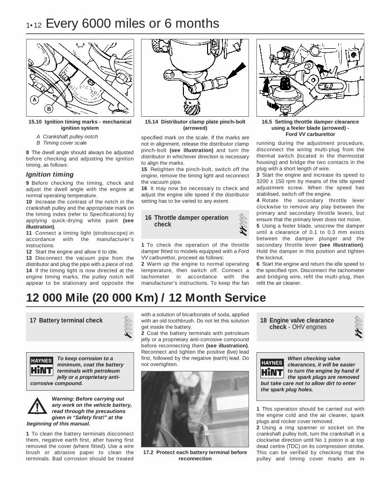
Ignition timing9 Before checking the timing, check andadjust the dwell angle with the engine atnormal operating temperature.10 Increase the contrast of the notch in thecrankshaft pulley and the appropriate mark onthe timing index (refer to Specifications) byapplying quick-drying white paint (seeillustration).11 Connect a timing light (stroboscope) inaccordance with the manufacturer’sinstructions.12 Start the engine and allow it to idle.13 Disconnect the vacuum pipe from thedistributor and plug the pipe with a piece of rod.14 If the timing light is now directed at theengine timing marks, the pulley notch willappear to be stationary and opposite the
specified mark on the scale. If the marks arenot in alignment, release the distributor clamppinch-bolt (see illustration) and turn thedistributor in whichever direction is necessaryto align the marks.15 Retighten the pinch-bolt, switch off theengine, remove the timing light and reconnectthe vacuum pipe.16 It may now be necessary to check andadjust the engine idle speed if the distributorsetting has to be varied to any extent.
16 Throttle damper operationcheck 2
1 To check the operation of the throttledamper fitted to models equipped with a FordVV carburettor, proceed as follows:2 Warm up the engine to normal operatingtemperature, then switch off. Connect atachometer in accordance with themanufacturer’s instructions. To keep the fan
running during the adjustment procedure,disconnect the wiring multi-plug from thethermal switch (located in the thermostathousing) and bridge the two contacts in theplug with a short length of wire.3 Start the engine and increase its speed to3200 ± 150 rpm by means of the idle speedadjustment screw. When the speed hasstabilised, switch off the engine.4 Rotate the secondary throttle leverclockwise to remove any play between theprimary and secondary throttle levers, butensure that the primary lever does not move.5 Using a feeler blade, unscrew the damperuntil a clearance of 0.1 to 0.3 mm existsbetween the damper plunger and thesecondary throttle lever (see illustration).Hold the damper in this position and tightenthe locknut.6 Start the engine and return the idle speed tothe specified rpm. Disconnect the tachometerand bridging wire, refit the multi-plug, thenrefit the air cleaner.
17 Battery terminal check 1
1 To clean the battery terminals disconnectthem, negative earth first, after having firstremoved the cover (where fitted). Use a wirebrush or abrasive paper to clean theterminals. Bad corrosion should be treated
with a solution of bicarbonate of soda, appliedwith an old toothbrush. Do not let this solutionget inside the battery.2 Coat the battery terminals with petroleumjelly or a proprietary anti-corrosive compoundbefore reconnecting them (see illustration).Reconnect and tighten the positive (live) leadfirst, followed by the negative (earth) lead. Donot overtighten.
18 Engine valve clearancecheck - OHV engines 2
1 This operation should be carried out withthe engine cold and the air cleaner, sparkplugs and rocker cover removed.2 Using a ring spanner or socket on thecrankshaft pulley bolt, turn the crankshaft in aclockwise direction until No 1 piston is at topdead centre (TDC) on its compression stroke.This can be verified by checking that thepulley and timing cover marks are in
1•12 Every 6000 miles or 6 months
15.10 Ignition timing marks - mechanicalignition system
A Crankshaft pulley notchB Timing cover scale
16.5 Setting throttle damper clearanceusing a feeler blade (arrowed) -
Ford VV carburettor
17.2 Protect each battery terminal beforereconnection
15.14 Distributor clamp plate pinch-bolt(arrowed)
12 000 Mile (20 000 Km) / 12 Month Service
To keep corrosion to aminimum, coat the batteryterminals with petroleumjelly or a proprietary anti-
corrosive compound.
When checking valveclearances, it will be easierto turn the engine by hand ifthe spark plugs are removed
but take care not to allow dirt to enterthe spark plug holes.
Warning: Before carrying outany work on the vehicle battery,read through the precautionsgiven in “Safety first!” at the
beginning of this manual.
alignment and that the valves of No 4 cylinderare rocking. When the valves are rocking, thismeans that the slightest rotation of thecrankshaft pulley in either direction will causeone rocker arm to move up and the other tomove down.3 Numbering from the thermostat housingend of the cylinder head, the valves areidentified as follows:
Valve No Cylinder no1 - Exhaust 12 - Inlet 13 - Exhaust 24 - Inlet 25 - Exhaust 36 - Inlet 37 - Exhaust 48 - Inlet 4
4 Adjust the valve clearances by following thesequence given in the following table. Turnthe crankshaft pulley 180° (half a turn) afteradjusting each pair:
Valves rocking Valves to adjust7 and 8 1 (Exhaust), 2 (Inlet)5 and 6 3 (Exhaust), 4 (Inlet)1 and 2 7 (Exhaust), 8 (Inlet)3 and 4 5 (Exhaust), 6 (Inlet)
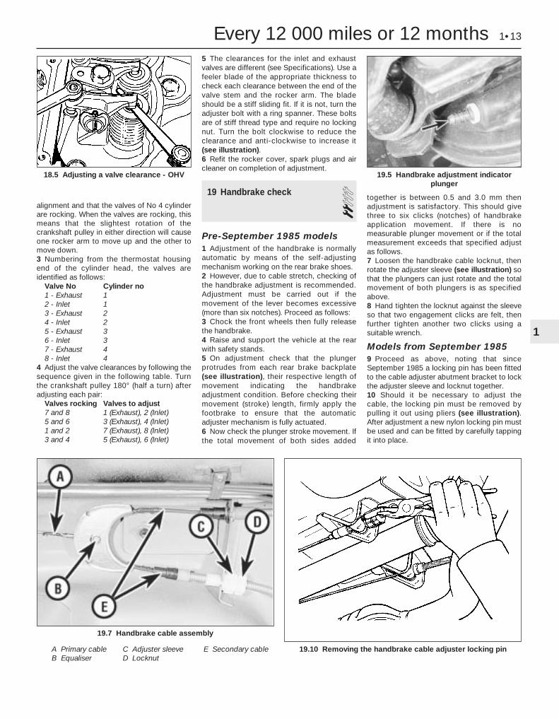
5 The clearances for the inlet and exhaustvalves are different (see Specifications). Use afeeler blade of the appropriate thickness tocheck each clearance between the end of thevalve stem and the rocker arm. The bladeshould be a stiff sliding fit. If it is not, turn theadjuster bolt with a ring spanner. These boltsare of stiff thread type and require no lockingnut. Turn the bolt clockwise to reduce theclearance and anti-clockwise to increase it(see illustration).6 Refit the rocker cover, spark plugs and aircleaner on completion of adjustment.
19 Handbrake check 2Pre-September 1985 models1 Adjustment of the handbrake is normallyautomatic by means of the self-adjustingmechanism working on the rear brake shoes.2 However, due to cable stretch, checking ofthe handbrake adjustment is recommended.Adjustment must be carried out if themovement of the lever becomes excessive(more than six notches). Proceed as follows:3 Chock the front wheels then fully releasethe handbrake.4 Raise and support the vehicle at the rearwith safety stands.5 On adjustment check that the plungerprotrudes from each rear brake backplate(see illustration), their respective length ofmovement indicating the handbrakeadjustment condition. Before checking theirmovement (stroke) length, firmly apply thefootbrake to ensure that the automaticadjuster mechanism is fully actuated.6 Now check the plunger stroke movement. Ifthe total movement of both sides added
together is between 0.5 and 3.0 mm thenadjustment is satisfactory. This should givethree to six clicks (notches) of handbrakeapplication movement. If there is nomeasurable plunger movement or if the totalmeasurement exceeds that specified adjustas follows.7 Loosen the handbrake cable locknut, thenrotate the adjuster sleeve (see illustration) sothat the plungers can just rotate and the totalmovement of both plungers is as specifiedabove.8 Hand tighten the locknut against the sleeveso that two engagement clicks are felt, thenfurther tighten another two clicks using asuitable wrench.
Models from September 19859 Proceed as above, noting that sinceSeptember 1985 a locking pin has been fittedto the cable adjuster abutment bracket to lockthe adjuster sleeve and locknut together.10 Should it be necessary to adjust thecable, the locking pin must be removed bypulling it out using pliers (see illustration).After adjustment a new nylon locking pin mustbe used and can be fitted by carefully tappingit into place.
Every 12 000 miles or 12 months 1•13
19.10 Removing the handbrake cable adjuster locking pin
19.7 Handbrake cable assembly
A Primary cableB Equaliser
C Adjuster sleeveD Locknut
E Secondary cable
19.5 Handbrake adjustment indicatorplunger
18.5 Adjusting a valve clearance - OHV
1
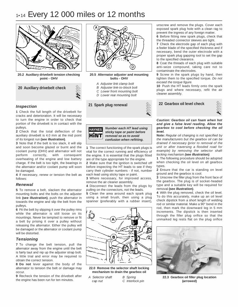
20 Auxiliary drivebelt check 2Inspection1 Check the full length of the drivebelt forcracks and deterioration. It will be necessaryto turn the engine in order to check thatportion of the drivebelt is in contact with thepulleys.2 Check that the total deflection of theauxiliary drivebelt is 4.0 mm at the mid pointof its longest run (see illustration).3 Note that if the belt is too slack, it will slipand soon become glazed or burnt and thecoolant pump (OHV) and alternator will notperform correctly, with consequentoverheating of the engine and low batterycharge. If the belt is too tight, the bearings inthe alternator and/or coolant pump will soonbe damaged.4 If necessary, renew or tension the belt asfollows:
Renewal5 To remove a belt, slacken the alternatormounting bolts and the bolts on the adjusterlink (see illustration), push the alternator intowards the engine and slip the belt from thepulleys.6 Fit the belt by slipping it over the pulley rimswhile the alternator is still loose on itsmountings. Never be tempted to remove or fita belt by prising it over a pulley withoutreleasing the alternator. Either the pulley willbe damaged or the alternator or coolant pumpwill be distorted.
Tensioning7 To change the belt tension, pull thealternator away from the engine until the beltis fairly taut and nip up the adjuster strap bolt.A little trial and error may be required toobtain the correct tension.8 Do not lever against the body of thealternator to tension the belt or damage mayoccur.9 Recheck the tension of the drivebelt afterthe engine has been run for ten minutes.
21 Spark plug renewal 1
1 The correct functioning of the spark plugs isvital for the correct running and efficiency ofthe engine. It is essential that the plugs fittedare of the type appropriate for the engine.2 Make sure that the ignition is switched offbefore inspecting the HT leads to see if theycarry their cylinder numbers - if not, numbereach lead using sticky tape or paint.3 Where necessary, for improved access,remove the air cleaner assembly.4 Disconnect the leads from the plugs bypulling on the connectors, not the leads.5 Clean the area around each spark plugusing a small brush, then using a plugspanner (preferably with a rubber insert),
unscrew and remove the plugs. Cover eachexposed spark plug hole with a clean rag toprevent the ingress of any foreign matter.6 Before fitting new spark plugs, check thatthe threaded connector sleeves are tight. 7 Check the electrode gap of each plug witha feeler blade of the specified thickness and ifnecessary, bend the outer electrode with aproper spark plug gapping tool to set the gapto the specified clearance.8 Coat the threads of each plug with suitableanti-seize compound, taking care not tocontaminate the electrodes.9 Screw in the spark plugs by hand, thentighten them to the specified torque. Do notexceed the torque figure.10 Push the HT leads firmly onto the sparkplugs and where necessary, refit the aircleaner assembly.
22 Gearbox oil level check 1Caution: Gearbox oil can foam when hotand give a false level reading. Allow thegearbox to cool before checking the oillevel.Note: Regular oil changing is not specified bythe manufacturers but the gearbox oil can bedrained if necessary (prior to removal of theunit or after traversing a flooded road forexample) by removing the selector shaftlocking mechanism (see illustration).1 The following procedure should be adoptedwhen checking the oil level on all gearboxtypes.2 Ensure that the car is standing on levelground and the gearbox is cool.3 Unscrew the filler plug from the front face ofthe gearbox. The plug is of socket-headedtype and a suitable key will be required forremoval (see illustration).4 With the plug removed, check the oil level.To do this accurately, make up an oil levelcheck dipstick from a short length of weldingrod or similar material. Make a 90° bend in therod, then mark the downward leg in 5 mmincrements. The dipstick is then insertedthrough the filler plug orifice so that theunmarked leg rests flat on the plug orifice
1•14 Every 12 000 miles or 12 months
20.2 Auxiliary drivebelt tension checkingpoint - OHV
22.3 Gearbox oil filler plug location(arrowed)
22.0 Remove the selector shaft lockingmechanism to drain the gearbox oil
A Selector shaftcap nut
B SpringC Interlock pin
20.5 Alternator adjuster and mountingbolts - OHV
A Adjuster link clamp boltB Adjuster link-to-block boltC Lower front mounting boltD Lower rear mounting bolt
Number each HT lead usingsticky tape or paint beforeremoval so as to avoidconfusion when refitting.

threads, with the marked leg dipped in the oil.Withdraw the dipstick and read off the level ofoil.5 On gearboxes manufactured up to August1985 the oil level must be maintained between5 and 10 mm below the lower edge of the fillerplug hole.6 On gearboxes manufactured fromSeptember 1985 onwards the oil level mustbe maintained between 0 and 5 mm below thelower edge of the filler plug hole.7 To determine the date of gearboxmanufacture, locate the aluminium build codetag which will be attached to one of thegearbox housing retaining bolts. The gearboxpart number is stamped on the tag and if thelast letter of the part number suffix is a “D”,then the gearbox is of the early type. If the lastletter of the suffix is an “E”, then the gearboxis of the later type.8 Top-up the gearbox with the specified typeof oil if necessary until the level is correct forthe gearbox type (see “Lubricants and fluids”).Take care not to overfill the unit as this canlead to excessive heat build-up, increasedleakage and impaired gear changing.9 On completion, refit the filler plug.
23 Contact breaker pointrenewal and distributorlubrication - OHV engines
31 If necessary, remove the air cleanerassembly to allow ready access to thedistributor. Identify and disconnect the leadsfrom the spark plugs, prise down thedistributor cap clips or remove the screws,and place the cap and leads to one side.2 Remove the rotor arm.3 Pull off the contact breaker LT lead from thepoints (see illustration).4 Unscrew and remove the screw from thefixed contact arm. Take great care not to dropthe screw into the interior of the distributor: ifnecessary, cover the openings in the
baseplate with rag before starting to removethe screw.5 With the screw removed, lift out the contactbreaker assembly.6 Fit and adjust the new contact breaker set,leaving the securing screw loose until the gaphas been set.7 Apply a little high melting-point grease tothe distributor cam. (Grease may be suppliedwith the new contact breaker set.)8 Refit the rotor arm and the distributor capand reconnect the spark plug leads in theirpreviously noted location.9 Check and adjust the dwell angle and theignition timing.
24 Steering and suspensionsecurity check 1
1 Check the shock absorbers by bouncingthe vehicle up and down at each corner inturn. When released, it should come to restwithin one complete oscillation. Continuedmovement, or squeaking and groaning noisesfrom the shock absorber suggests thatrenewal is required.2 With the weight of the vehicle on itsroadwheels, inspect all of the suspension
flexible bushes for wear and check the torquewrench settings of all bolts and nuts.3 Raise and support the vehicle. Examine allsteering and suspension components forwear, damage and fluid leakage. Payparticular attention to dust covers and gaiters(see illustration), which if renewed promptlywhen damaged can save further damage tothe component protected.4 At the same intervals, check the frontsuspension lower arm balljoints for wear bylevering up the arms (see illustration).Balljoint free movement must not exceed 0.5mm. The track rod end balljoints can bechecked in a similar manner, or by observingthem whilst an assistant rocks the steeringwheel back and forth. If the lower arm balljointis worn, the complete lower arm must berenewed.5 Wheel bearings can be checked for wear byspinning the relevant roadwheel. Anyroughness or excessive noise indicates wornbearings, which must be renewed, as noadjustment is possible. It is unlikely that anywear will be evident unless the vehicle hascovered a very high mileage. It should benoted that it is normal for the bearings toexhibit slight endfloat, which is perceptible aswheel rock at the wheel rim.
25 Underbody inspection 11 Except on vehicles with a wax-basedunderbody protective coating, have the wholeof the underframe of the vehicle steam-cleaned, engine compartment included, sothat a thorough inspection can be carried outto see what minor repairs and renovations arenecessary. 2 Steam-cleaning is available at manygarages and is necessary for the removal ofthe accumulation of oily grime whichsometimes is allowed to become thick in
Every 12 000 miles or 12 months 1•15
24.4 Apply leverage to check for excessiveballjoint wear
24.3 Inspect the steering rack bellows23.3 Contact breaker points removal
A LT lead connectorB Securing screw
C Vacuum advance strutcirclip
1

certain areas. If steam-cleaning facilities arenot available, there are some excellent greasesolvents available, which can be brush-applied; the dirt can then be simply hosed off.3 After cleaning, position the vehicle over a pit,or raise it at front and rear on ramps or axlestands (see “Jacking and vehicle support”).4 Using a strong light, work around theunderside of the vehicle, inspecting it forcorrosion or damage. If either is found, referto Chapter 11 for details of repair.
26 Brake pipe and hose check 11 Periodically inspect the rigid brake pipes forrust and other damage, and the flexible hosesfor cracks, splits or “ballooning” (seeillustration). Have an assistant depress thebrake pedal (ignition on) and inspect the hoseand pipe unions for leaks. Renew anydefective item without delay.
27 Road test 1Instruments and electricalequipment1 Check the operation of all instruments andelectrical equipment.2 Make sure that all instruments readcorrectly, switch on all electrical equipment inturn to check that it functions properly.
Steering and suspension3 Check for any abnormalities in the steering,suspension, handling or road “feel”.4 Drive the vehicle, and check that there areno unusual vibrations or noises.5 Check that the steering feels positive, withno excessive “sloppiness”, or roughness, andcheck for any suspension noises whencornering, or when driving over bumps.
Drivetrain6 Check the performance of the engine,clutch, transmission and driveshafts.7 Listen for any unusual noises from theengine, clutch and transmission.8 Make sure that the engine runs smoothlywhen idling, and that there is no hesitationwhen accelerating.9 Where applicable, check that the clutchaction is smooth and progressive, that thedrive is taken up smoothly, and that the pedaltravel is not excessive. Also listen for anynoises when the clutch pedal is depressed.10 Check that all gears can be engagedsmoothly, without noise, and that the gearlever action is not abnormally vague or“notchy”.
Check the operation andperformance of the brakingsystem11 Make sure that the vehicle does not pull toone side when braking, and that the wheelsdo not lock prematurely when braking hard.12 Check that there is no vibration throughthe steering when braking.13 Check that the handbrake operatescorrectly, without excessive movement of the
lever, and that it holds the vehicle stationaryon a slope.14 Test the operation of the brake servo unitas follows. With the engine off, depress thefootbrake four or five times to exhaust thevacuum. Start the engine, holding the brakepedal depressed. As the engine starts, thereshould be a noticeable “give” in the brakepedal as vacuum builds up. Allow the engineto run for at least two minutes, and thenswitch it off. If the brake pedal is depressednow, it should be possible to detect a hissfrom the servo as the pedal is depressed.After about four or five applications, no furtherhissing should be heard, and the pedal shouldfeel considerably firmer.
28 Crankcase ventilationsystem check 1
1 Inspect the crankcase ventilation systemfor blockage or damage. A blocked hose cancause a build-up of crankcase pressure,which in turn can cause oil leaks.2 Inspect each hose for distortion, perishingand correct routing. 3 Clean the oil filler cap with solvent andcheck that the vent hose connections are notblocked (see illustration).4 Clean the emission control orifice located inthe oil filler assembly with solvent (seeillustration).
1•16 Every 12 000 miles or 12 months
26.1 Bend flexible brake hoses to checkfor splitting and decay
28.4 Clean emission control orifice insolvent - OHV shown
28.3 Oil filler cap and breather hoses

29 Air cleaner temperaturecontrol check 2
Note: A vacuum pump will be required for thischeck if the heat sensor or diaphragm unit isat fault.1 The air cleaner temperature control unit canbe checked for operation whilst the engine iscold. Look into the air inlet spout and checkthat the air control flap valve is in the shutposition (see illustration).2 Now start the engine and allow it to idle.The flap valve should open fully to allow thewarm air to be drawn into the cleaner unitfrom the exhaust manifold ducting. As theengine warms up to its normal operatingtemperature the flap valve shouldprogressively close to allow cooler air to enterthe cleaner unit.3 If the valve is stuck in the shut position,check the vacuum lines for condition andsecurity. If these are in order, then the heatsensor or diaphragm unit is at fault. Proceedas follows:4 Detach the diaphragm-to-heat sensorvacuum pipe (at the sensor end) and connectup a vacuum pump to the diaphragm. Pumpand apply a vacuum up to 100 mm of mercuryand retain this whilst checking the air flap.5 If the flap opens, the heat sensor isdefective and must be renewed, but if itremains shut then the diaphragm or controlflap is faulty.6 Disconnect the vacuum pump andreconnect the vacuum pipe to the sensor unit.
30 Emission control filterelement renewal - CVHengines
11 Gain access to the emission control filter bydetaching the hose from the air cleaner unit(see illustration).
2 Withdraw the used filter and fit a new item.Ensure that the hose is securely reconnected.
31 Air cleaner element renewal 11 Renew the air cleaner element by firstremoving the air cleaner unit lid. To do this,undo and remove the retaining screws andprise free the lid from the retaining clipsaround its periphery (see illustration).2 Remove and discard the paper element andwipe out the air cleaner casing (seeillustration).3 Place the new element in position and refitthe lid.
32 Brake hydraulic system sealand hose renewal 3
If in doubt as to the condition of any of thebrake system seals and hoses, then renewdefective items whilst referring to the relevantSections of Chapter 9.
33 Brake hydraulic fluid renewal 21 An assistant and bleeding equipment willbe needed. A considerable quantity ofhydraulic fluid will be required - probablyabout 2 litres.
2 Slacken the front wheel nuts. Raise andsupport the front of the vehicle and removethe front wheels.3 Remove the hydraulic fluid reservoir cap.4 Open both front bleed screws one full turn.Attach one bleed tube to each screw, placingthe free end of each tube in a jar.5 Pump the brake pedal to expel fluid fromthe bleed screws. Pause after each upstroketo allow the master cylinder to refill.
Every 24 000 miles or 2 years 1•17
31.1 Remove the air cleaner lid securingscrews . . .
30.1 Detach hose downwards for accessto crankcase emission filter in air cleaner
body
29.1 Air cleaner inlet sensor anddiaphragm flap valve operating modes
1 Sensor cold 2 Sensor hot
1
24 000 Mile (40 000 Km) / every 2 years
36 000 Mile (60 000 Km) / every 3 years
31.2 . . . to expose the air cleaner element
6 When air emerges from both bleed screws,stop pumping. Detach the left-hand caliperwithout disconnecting it and remove theinboard brake pad.7 Depress the caliper piston, using apurpose-made tool or a blunt item such as atyre lever, to force more fluid out of thecaliper. Hold the piston depressed and havethe assistant pump the pedal until air emergesfrom the bleed screw again.8 Tighten the bleed screw on the left-handcaliper. Loosely refit the caliper and pad sothat the piston is not accidentally ejected.9 Repeat the purging operation on the right-hand caliper, but do not refit it or tighten thebleed screw yet.10 Fill the reservoir with fresh hydraulic fluid.Position the bleed jar for the right-handcaliper at least 300 mm above the level of thebleed screw.11 Have the assistant pump the brake pedaluntil fluid free of bubbles emerges from thebleed screw. Tighten the bleed screw at theend of a downstroke.
12 Place a piece of wood in the caliper jawsto limit piston travel. Keep your fingers clearof the piston. Have the assistant depress thebrake pedal gently in order to move thecaliper piston out.13 With the pedal held depressed, slackenthe bleed screw on the right-hand caliper andagain depress the piston. Tighten the bleedscrew when the piston is retracted. The pedalcan now be released.14 Disconnect the bleed tube. Refit the right-hand brake pad and caliper.15 Remove the left-hand caliper and inboardpad again. Carry out the operations describedin paragraphs 10 to 14 on the left-handcaliper.16 Bleed the rear brakes as described inChapter 9.17 Refit the front wheels, lower the vehicleand tighten the wheel nuts.18 Pump the brake pedal to bring the padsup to the discs, then make a final check of thehydraulic fluid level. Top-up and refit thereservoir cap.
34 Timing belt renewal - CVHengines 3
Timing belt renewal is recommended forCVH engines. Refer to Chapter 2, Part B forthe appropriate renewal procedure.
35 Front wheel alignment check 3Due to the need for precision equipment to
accurately measure the small angles of thesteering and suspension settings appertainingto front wheel alignment, it is preferable toleave this work to a specialist. However, if youwish to check front wheel alignment yourself,refer to the information given in Chapter 10.
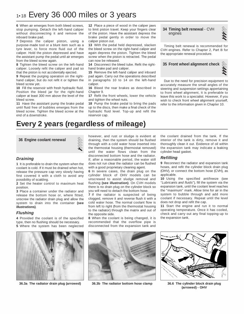
36 Engine coolant renewal 1Draining1 It is preferable to drain the system when thecoolant is cold. If it must be drained when hot,release the pressure cap very slowly havingfirst covered it with a cloth to avoid anypossibility of scalding. 2 Set the heater control to maximum heatposition.3 Place a container under the radiator andrelease the bottom hose or, where fitted,unscrew the radiator drain plug and allow thesystem to drain into the container (seeillustrations).
Flushing4 Provided the coolant is of the specifiedtype, then no flushing should be necessary.5 Where the system has been neglected
however, and rust or sludge is evident atdraining, then the system should be flushedthrough with a cold water hose inserted intothe thermostat housing (thermostat removed)until the water flows clean from thedisconnected bottom hose and the radiator.If, after a reasonable period, the water stilldoes not run clear the radiator can be flushedwith a good proprietary cleaning agent.6 In severe cases, the drain plug on thecylinder block of OHV models can beunscrewed to assist sludge removal andflushing (see illustration). On CVH modelsthere is no drain plug on the cylinder block soyou will need to detach the bottom hose.7 If the radiator is suspected of beingclogged, remove it and reverse flush it with acold water hose. The normal coolant flow isfrom left to right (from the thermostat housingto the radiator) through the matrix and out ofthe opposite side.8 When the coolant is being changed, it isrecommended that the overflow pipe isdisconnected from the expansion tank and
the coolant drained from the tank. If theinterior of the tank is dirty, remove it andthoroughly clean it out. Evidence of oil withinthe expansion tank may indicate a leakingcylinder head gasket.
Refilling9 Reconnect the radiator and expansion tankhoses, and refit the cylinder block drain plug(OHV), or connect the bottom hose (CVH), asapplicable.10 Using the specified antifreeze (see“Lubricants and fluids”), fill the system via theexpansion tank, until the coolant level reachesthe “maximum” mark. Allow time for air in thesystem to bubble through and add morecoolant if necessary. Repeat until the leveldoes not drop and refit the cap.11 Start the engine and run it to normaloperating temperature. Once it has cooled,check and carry out any final topping-up tothe expansion tank.
1•18 Every 36 000 miles or 3 years
36.6 The cylinder block drain plug(arrowed) - OHV
36.3b The radiator bottom hose clamp36.3a The radiator drain plug (arrowed)
Every 2 years (regardless of mileage)

2A
GeneralEngine type . . . . . . . . . . . . . . . . . . . . . . . . . . . . . . . . . . . . . . . . . . . . . . . Four-cylinder, overhead valve, water-cooled
1.0 litre 1.1 litreFiring order (No 1 at timing cover end) . . . . . . . . . . . . . . . . . . . . . . . . . . 1-2-4-3 1-2-4-3Bore . . . . . . . . . . . . . . . . . . . . . . . . . . . . . . . . . . . . . . . . . . . . . . . . . . . . 73.96 mm 73.96 mmStroke . . . . . . . . . . . . . . . . . . . . . . . . . . . . . . . . . . . . . . . . . . . . . . . . . . . 55.70 mm 64.98 mmCubic capacity . . . . . . . . . . . . . . . . . . . . . . . . . . . . . . . . . . . . . . . . . . . . 957 cc 1117 ccCompression ratio . . . . . . . . . . . . . . . . . . . . . . . . . . . . . . . . . . . . . . . . . 8.5 : 1 9.5 : 1Compression pressure at starter speed . . . . . . . . . . . . . . . . . . . . . . . . . 9.5 to 11.5 kgf/cm2 13.3 to 15.3 kgf/cm2
Idle speed (rpm) . . . . . . . . . . . . . . . . . . . . . . . . . . . . . . . . . . . . . . . . . . . 750 to 850 750 to 850Maximum continuous engine speed (rpm) . . . . . . . . . . . . . . . . . . . . . . . 5950 5450Engine output (DIN) . . . . . . . . . . . . . . . . . . . . . . . . . . . . . . . . . . . . . . . . 33 kW at 5750 rpm 37 kW at 5000 rpmEngine torque (DIN) . . . . . . . . . . . . . . . . . . . . . . . . . . . . . . . . . . . . . . . . 6.9 kgf m at 3700 rpm 8.4 kgf m at 2700 rpm
Cylinder blockNumber of main bearings . . . . . . . . . . . . . . . . . . . . . . . . . . . . . . . . . . . . 3Cylinder bore diameter:
Standard (1) . . . . . . . . . . . . . . . . . . . . . . . . . . . . . . . . . . . . . . . . . . . . 73.940 to 73.950 mmStandard (2) . . . . . . . . . . . . . . . . . . . . . . . . . . . . . . . . . . . . . . . . . . . . 73.950 to 73.960 mmStandard (3) . . . . . . . . . . . . . . . . . . . . . . . . . . . . . . . . . . . . . . . . . . . . 73.960 to 73.970 mm Standard (4) and service . . . . . . . . . . . . . . . . . . . . . . . . . . . . . . . . . . . 73.970 to 73.980 mm
Oversizes:0.5 . . . . . . . . . . . . . . . . . . . . . . . . . . . . . . . . . . . . . . . . . . . . . . . . . . . . 74.500 to 74.510 mm1.0 . . . . . . . . . . . . . . . . . . . . . . . . . . . . . . . . . . . . . . . . . . . . . . . . . . . . 75.000 to 75.010 mm
Main bearing bore:Standard . . . . . . . . . . . . . . . . . . . . . . . . . . . . . . . . . . . . . . . . . . . . . . . 60.623 to 60.636 mmOversize . . . . . . . . . . . . . . . . . . . . . . . . . . . . . . . . . . . . . . . . . . . . . . . 61.003 to 61.016 mm
Camshaft bearing bore:Standard . . . . . . . . . . . . . . . . . . . . . . . . . . . . . . . . . . . . . . . . . . . . . . . 42.888 to 42.918 mmOversize . . . . . . . . . . . . . . . . . . . . . . . . . . . . . . . . . . . . . . . . . . . . . . . 43.396 to 43.420 mm
Central main bearing width (less thrustwashers) . . . . . . . . . . . . . . . . . . 22.04 to 22.10 mm
CrankshaftEndfloat . . . . . . . . . . . . . . . . . . . . . . . . . . . . . . . . . . . . . . . . . . . . . . . . . . 0.072 to 0.285 mmMain journal diameter:
Standard . . . . . . . . . . . . . . . . . . . . . . . . . . . . . . . . . . . . . . . . . . . . . . . 56.990 to 57.000 mmYellow dot . . . . . . . . . . . . . . . . . . . . . . . . . . . . . . . . . . . . . . . . . . . . . . 56.980 to 56.990 mm0.254 undersize . . . . . . . . . . . . . . . . . . . . . . . . . . . . . . . . . . . . . . . . . . 56.726 to 56.746 mm0.508 undersize . . . . . . . . . . . . . . . . . . . . . . . . . . . . . . . . . . . . . . . . . . 56.472 to 56.492 mm0.762 undersize . . . . . . . . . . . . . . . . . . . . . . . . . . . . . . . . . . . . . . . . . . 56.218 to 56.238 mm
Chapter 2 Part A:OHV engine repair procedures
Crankshaft front oil seal - renewal . . . . . . . . . . . . . . . . . . . . . . . . . . . .8Cylinder head - removal and refitting . . . . . . . . . . . . . . . . . . . . . . . . . .4Cylinder head and pistons - decarbonising . . . . . . . . . . . . . . . . . . . .15Engine - dismantling . . . . . . . . . . . . . . . . . . . . . . . . . . . . . . . . . . . . . .13Engine - examination and renovation . . . . . . . . . . . . . . . . . . . . . . . . .14Engine - reassembly . . . . . . . . . . . . . . . . . . . . . . . . . . . . . . . . . . . . . .16Engine/transmission mountings - removal and refitting . . . . . . . . . . .11Engine/transmission - reconnection and refitting . . . . . . . . . . . . . . . .17Engine/transmission - removal and separation . . . . . . . . . . . . . . . . .12
General information . . . . . . . . . . . . . . . . . . . . . . . . . . . . . . . . . . . . . . .1Oil filter and pump - removal and refitting . . . . . . . . . . . . . . . . . . . . .10Operations only possible with engine removed from vehicle . . . . . . . .3Operations possible without removing engine from vehicle . . . . . . . . .2Pistons/connecting rods - removal and refitting . . . . . . . . . . . . . . . . .9Rocker gear - dismantling and reassembly . . . . . . . . . . . . . . . . . . . . .7Sump - removal and refitting . . . . . . . . . . . . . . . . . . . . . . . . . . . . . . . .6Valve clearances - adjustment . . . . . . . . . . . . . . . . . . . . . . . . . . . . . . .5
2A•1
Specifications
Contents
Easy, suitable fornovice with littleexperience
Fairly easy, suitablefor beginner withsome experience
Fairly difficult,suitable for competentDIY mechanic
Difficult, suitable forexperienced DIYmechanic
Very difficult,suitable for expert DIYor professional
Degrees of difficulty
54321

Crankshaft (continued)Main bearing shell width . . . . . . . . . . . . . . . . . . . . . . . . . . . . . . . . . . . . . 21.2 to 21.6 mmMain bearing shell play . . . . . . . . . . . . . . . . . . . . . . . . . . . . . . . . . . . . . . 0.009 to 0.046 mmCrankpin (big-end) diameter:
Standard . . . . . . . . . . . . . . . . . . . . . . . . . . . . . . . . . . . . . . . . . . . . . . . 42.99 to 43.01 mm0.254 undersize . . . . . . . . . . . . . . . . . . . . . . . . . . . . . . . . . . . . . . . . . . 42.74 to 42.76 mm 0.508 undersize . . . . . . . . . . . . . . . . . . . . . . . . . . . . . . . . . . . . . . . . . . 42.49 to 42.51 mm0.762 undersize . . . . . . . . . . . . . . . . . . . . . . . . . . . . . . . . . . . . . . . . . . 42.24 to 42.26 mm
Thrustwasher thicknesses:Standard . . . . . . . . . . . . . . . . . . . . . . . . . . . . . . . . . . . . . . . . . . . . . . . 2.80 to 2.85 mmOversize . . . . . . . . . . . . . . . . . . . . . . . . . . . . . . . . . . . . . . . . . . . . . . . 2.99 to 3.04 mm
CamshaftNumber of bearings . . . . . . . . . . . . . . . . . . . . . . . . . . . . . . . . . . . . . . . . 3Camshaft bearing diameter . . . . . . . . . . . . . . . . . . . . . . . . . . . . . . . . . . 39.615 to 39.635 mmBearing bush inside diameter . . . . . . . . . . . . . . . . . . . . . . . . . . . . . . . . . 39.662 to 39.682 mmCamshaft thrust plate thickness . . . . . . . . . . . . . . . . . . . . . . . . . . . . . . . 4.457 to 4.508 mmCamshaft endfloat . . . . . . . . . . . . . . . . . . . . . . . . . . . . . . . . . . . . . . . . . 0.062 to 0.193 mmCam lift:
Inlet valve . . . . . . . . . . . . . . . . . . . . . . . . . . . . . . . . . . . . . . . . . . . . . . 5.300 mmExhaust valve . . . . . . . . . . . . . . . . . . . . . . . . . . . . . . . . . . . . . . . . . . . 5.300 mm
Cam length (heel to toe):Inlet . . . . . . . . . . . . . . . . . . . . . . . . . . . . . . . . . . . . . . . . . . . . . . . . . . . 32.288 to 32.516 mmExhaust . . . . . . . . . . . . . . . . . . . . . . . . . . . . . . . . . . . . . . . . . . . . . . . . 32.615 to 32.846 mm
PistonsDiameter:
Standard (1) . . . . . . . . . . . . . . . . . . . . . . . . . . . . . . . . . . . . . . . . . . . . 73.910 to 73.920 mmStandard (2) . . . . . . . . . . . . . . . . . . . . . . . . . . . . . . . . . . . . . . . . . . . . 73.920 to 73.930 mmStandard (3) . . . . . . . . . . . . . . . . . . . . . . . . . . . . . . . . . . . . . . . . . . . . 73.930 to 73.940 mmStandard (4) . . . . . . . . . . . . . . . . . . . . . . . . . . . . . . . . . . . . . . . . . . . . 73.940 to 73.950 mmStandard service . . . . . . . . . . . . . . . . . . . . . . . . . . . . . . . . . . . . . . . . . 73.930 to 73.955 mm0.5 oversize . . . . . . . . . . . . . . . . . . . . . . . . . . . . . . . . . . . . . . . . . . . . . 74.460 to 74.485 mm1.0 oversize . . . . . . . . . . . . . . . . . . . . . . . . . . . . . . . . . . . . . . . . . . . . . 74.960 to 74.985 mm
Piston-to-bore clearance . . . . . . . . . . . . . . . . . . . . . . . . . . . . . . . . . . . . 0.015 to 0.050 mmPiston ring gap (fitted):
Top and 2nd rings . . . . . . . . . . . . . . . . . . . . . . . . . . . . . . . . . . . . . . . . 0.25 to 0.45 mmBottom ring . . . . . . . . . . . . . . . . . . . . . . . . . . . . . . . . . . . . . . . . . . . . . 0.20 to 0.40 mm
Bottom (oil control) ring gap position . . . . . . . . . . . . . . . . . . . . . . . . . . . In line with gudgeon pin2nd ring gap position . . . . . . . . . . . . . . . . . . . . . . . . . . . . . . . . . . . . . . . 90° to oil control ring gapTop ring gap position . . . . . . . . . . . . . . . . . . . . . . . . . . . . . . . . . . . . . . . 180° to oil control ring gap
Gudgeon pinsPin length . . . . . . . . . . . . . . . . . . . . . . . . . . . . . . . . . . . . . . . . . . . . . . . . 54.6 to 55.4 mmPin diameters:
White . . . . . . . . . . . . . . . . . . . . . . . . . . . . . . . . . . . . . . . . . . . . . . . . . . 20.622 to 20.625 mmRed . . . . . . . . . . . . . . . . . . . . . . . . . . . . . . . . . . . . . . . . . . . . . . . . . . . 20.625 to 20.628 mmBlue . . . . . . . . . . . . . . . . . . . . . . . . . . . . . . . . . . . . . . . . . . . . . . . . . . . 20.628 to 20.631 mmYellow . . . . . . . . . . . . . . . . . . . . . . . . . . . . . . . . . . . . . . . . . . . . . . . . . 20.631 to 20.634 mm
Connecting rod interference at 21°C (70°F) . . . . . . . . . . . . . . . . . . . . . . 0.013 to 0.045 mmPin-to-piston interference at 21°C (70°F) . . . . . . . . . . . . . . . . . . . . . . . . 0.005 to 0.011 mm
Connecting rodsBig-end bore diameter . . . . . . . . . . . . . . . . . . . . . . . . . . . . . . . . . . . . . . 46.685 to 46.705 mmSmall-end bore diameter . . . . . . . . . . . . . . . . . . . . . . . . . . . . . . . . . . . . 20.589 to 20.609 mmBearing shell inside diameter (fitted):
Standard . . . . . . . . . . . . . . . . . . . . . . . . . . . . . . . . . . . . . . . . . . . . . . . 43.016 to 43.050 mm0.254 undersize . . . . . . . . . . . . . . . . . . . . . . . . . . . . . . . . . . . . . . . . . . 42.768 to 42.802 mm0.508 undersize . . . . . . . . . . . . . . . . . . . . . . . . . . . . . . . . . . . . . . . . . . 42.518 to 42.552 mm0.762 undersize . . . . . . . . . . . . . . . . . . . . . . . . . . . . . . . . . . . . . . . . . . 42.268 to 42.302 mm1.016 undersize . . . . . . . . . . . . . . . . . . . . . . . . . . . . . . . . . . . . . . . . . . 42.018 to 42.052 mm
Journal-to-bearing shell clearance . . . . . . . . . . . . . . . . . . . . . . . . . . . . . 0.006 to 0.060 mm
Cylinder headValve seat angle (inlet and exhaust) . . . . . . . . . . . . . . . . . . . . . . . . . . . . 45°Valve seat width (inlet and exhaust) . . . . . . . . . . . . . . . . . . . . . . . . . . . . 1.20 to 1.75 mmLower correction angle (inlet and exhaust) . . . . . . . . . . . . . . . . . . . . . . . 30°Upper correction angle (inlet and exhaust) . . . . . . . . . . . . . . . . . . . . . . . 80°Upper correction angle - service cutter . . . . . . . . . . . . . . . . . . . . . . . . . 75°Valve stem bore (inlet and exhaust):
Standard . . . . . . . . . . . . . . . . . . . . . . . . . . . . . . . . . . . . . . . . . . . . . . . 7.907 to 7.938 mm0.381 oversize . . . . . . . . . . . . . . . . . . . . . . . . . . . . . . . . . . . . . . . . . . . 8.288 to 8.319 mm
2A•2 OHV engine repair procedures

ValvesClearances . . . . . . . . . . . . . . . . . . . . . . . . . . . . . . . . . . . . . . . . . . . . . . . See Servicing Specifications in Chapter 1Tappet diameter . . . . . . . . . . . . . . . . . . . . . . . . . . . . . . . . . . . . . . . . . . . 13.081 to 13.094 mmTappet clearance in cylinder block . . . . . . . . . . . . . . . . . . . . . . . . . . . . . 20.25 to 20.75 mmValve spring free length (inlet and exhaust) . . . . . . . . . . . . . . . . . . . . . . 42 mmValve lift (excluding clearance) (inlet and exhaust) . . . . . . . . . . . . . . . . . 8.367 mmValve head diameter:
Inlet . . . . . . . . . . . . . . . . . . . . . . . . . . . . . . . . . . . . . . . . . . . . . . . . . . . 32.89 to 33.15 mmExhaust . . . . . . . . . . . . . . . . . . . . . . . . . . . . . . . . . . . . . . . . . . . . . . . . 29.01 to 29.27 mm
Valve stem diameter:Inlet valves:
Standard . . . . . . . . . . . . . . . . . . . . . . . . . . . . . . . . . . . . . . . . . . . . . 7.868 to 7.886 mm0.076 oversize . . . . . . . . . . . . . . . . . . . . . . . . . . . . . . . . . . . . . . . . . 7.944 to 7.962 mm0.381 oversize . . . . . . . . . . . . . . . . . . . . . . . . . . . . . . . . . . . . . . . . . 8.249 to 8.267 mm
Exhaust valves:Standard . . . . . . . . . . . . . . . . . . . . . . . . . . . . . . . . . . . . . . . . . . . . . 7.846 to 7.864 mm0.076 oversize . . . . . . . . . . . . . . . . . . . . . . . . . . . . . . . . . . . . . . . . . 7.922 to 7.940 mm0.381 oversize . . . . . . . . . . . . . . . . . . . . . . . . . . . . . . . . . . . . . . . . . 8.227 to 8.245 mm
Valve stem-to-guide clearance:Inlet . . . . . . . . . . . . . . . . . . . . . . . . . . . . . . . . . . . . . . . . . . . . . . . . . . . 0.021 to 0.070 mmExhaust . . . . . . . . . . . . . . . . . . . . . . . . . . . . . . . . . . . . . . . . . . . . . . . . 0.043 to 0.092 mm
Valve timing:Inlet valve opens . . . . . . . . . . . . . . . . . . . . . . . . . . . . . . . . . . . . . . . . . 14° BTDCInlet valve closes . . . . . . . . . . . . . . . . . . . . . . . . . . . . . . . . . . . . . . . . . 46° ABDCExhaust valve opens . . . . . . . . . . . . . . . . . . . . . . . . . . . . . . . . . . . . . . 65° BBDCExhaust valve closes . . . . . . . . . . . . . . . . . . . . . . . . . . . . . . . . . . . . . . 11° ATDC
Lubrication systemMinimum oil pressure at 80°C (175°F) . . . . . . . . . . . . . . . . . . . . . . . . . . 0.6 kgf/cm2 at 750 rpmWarning light operates at . . . . . . . . . . . . . . . . . . . . . . . . . . . . . . . . . . . . 0.32 to 0.53 kgf/cm2
Relief valve opening pressure . . . . . . . . . . . . . . . . . . . . . . . . . . . . . . . . . 2.41 to 2.75 kgf/cm2
Oil pump clearances:Outer rotor-to-housing . . . . . . . . . . . . . . . . . . . . . . . . . . . . . . . . . . . . 0.14 to 0.26 mmInner-to-outer rotor . . . . . . . . . . . . . . . . . . . . . . . . . . . . . . . . . . . . . . . 0.051 to 0.127 mmRotors-to-cover endfloat . . . . . . . . . . . . . . . . . . . . . . . . . . . . . . . . . . 0.025 to 0.06 mm
Torque wrench settings Nm lbf ftMain bearing cap bolts . . . . . . . . . . . . . . . . . . . . . . . . . . . . . . . . . . . . . . 95 70Connecting rod (big-end) bolts . . . . . . . . . . . . . . . . . . . . . . . . . . . . . . . . 31 23Rear oil seal retainer bolts . . . . . . . . . . . . . . . . . . . . . . . . . . . . . . . . . . . 18 13Flywheel bolts . . . . . . . . . . . . . . . . . . . . . . . . . . . . . . . . . . . . . . . . . . . . . 68 50Chain tensioner bolts . . . . . . . . . . . . . . . . . . . . . . . . . . . . . . . . . . . . . . . 8 6Camshaft thrust plate bolts . . . . . . . . . . . . . . . . . . . . . . . . . . . . . . . . . . 4 3Camshaft sprocket bolts . . . . . . . . . . . . . . . . . . . . . . . . . . . . . . . . . . . . 19 14Timing cover bolts . . . . . . . . . . . . . . . . . . . . . . . . . . . . . . . . . . . . . . . . . 10 7Coolant pump bolts . . . . . . . . . . . . . . . . . . . . . . . . . . . . . . . . . . . . . . . . 10 7Crankshaft pulley bolt . . . . . . . . . . . . . . . . . . . . . . . . . . . . . . . . . . . . . . . 54 40Coolant pump pulley bolts . . . . . . . . . . . . . . . . . . . . . . . . . . . . . . . . . . . 10 7Starter motor bolts . . . . . . . . . . . . . . . . . . . . . . . . . . . . . . . . . . . . . . . . . 41 30Fuel pump bolts . . . . . . . . . . . . . . . . . . . . . . . . . . . . . . . . . . . . . . . . . . . 18 13Oil pump bolts . . . . . . . . . . . . . . . . . . . . . . . . . . . . . . . . . . . . . . . . . . . . 19 14Sump drain plug . . . . . . . . . . . . . . . . . . . . . . . . . . . . . . . . . . . . . . . . . . . 25 18Sump fixing bolts:
Stage 1 . . . . . . . . . . . . . . . . . . . . . . . . . . . . . . . . . . . . . . . . . . . . . . . . 8 6Stage 2 . . . . . . . . . . . . . . . . . . . . . . . . . . . . . . . . . . . . . . . . . . . . . . . . 11 8Stage 3 . . . . . . . . . . . . . . . . . . . . . . . . . . . . . . . . . . . . . . . . . . . . . . . . 11 8
Oil pressure sender . . . . . . . . . . . . . . . . . . . . . . . . . . . . . . . . . . . . . . . . . 15 11Coolant temperature sender . . . . . . . . . . . . . . . . . . . . . . . . . . . . . . . . . . 15 11Rocker shaft pedestal bolts . . . . . . . . . . . . . . . . . . . . . . . . . . . . . . . . . . 42 31Cylinder head bolts:
Stage 1 . . . . . . . . . . . . . . . . . . . . . . . . . . . . . . . . . . . . . . . . . . . . . . . . 15 11Stage 2 . . . . . . . . . . . . . . . . . . . . . . . . . . . . . . . . . . . . . . . . . . . . . . . . 48 35Stage 3 . . . . . . . . . . . . . . . . . . . . . . . . . . . . . . . . . . . . . . . . . . . . . . . . 88 65Stage 4 (after 15 minutes delay) . . . . . . . . . . . . . . . . . . . . . . . . . . . . . 109 80
Rocker cover screws . . . . . . . . . . . . . . . . . . . . . . . . . . . . . . . . . . . . . . . 4 3Exhaust manifold nuts and bolts . . . . . . . . . . . . . . . . . . . . . . . . . . . . . . 16 12Inlet manifold nuts and bolts . . . . . . . . . . . . . . . . . . . . . . . . . . . . . . . . . 19 14Carburettor flange nuts . . . . . . . . . . . . . . . . . . . . . . . . . . . . . . . . . . . . . . 19 14Thermostat housing cover bolts . . . . . . . . . . . . . . . . . . . . . . . . . . . . . . . 19 14Spark plugs . . . . . . . . . . . . . . . . . . . . . . . . . . . . . . . . . . . . . . . . . . . . . . . 19 14Engine-to-transmission bolts . . . . . . . . . . . . . . . . . . . . . . . . . . . . . . . . . 41 30Transmission oil filler plug . . . . . . . . . . . . . . . . . . . . . . . . . . . . . . . . . . . 25 18
OHV engine repair procedures 2A•3
2A

1 General information
The engine is of an overhead valve typebased upon the “Kent” design used in manyearlier Ford models. It is mounted transverselyat the front of the vehicle together with thetransmission to form a combined power train.
The engine is a water-cooled, four-cylinderin-line type, having overhead valves operatedby tappets, pushrods and rocker arms. Thecamshaft is located within the cylinder blockand chain-driven from the crankshaft. A gearon the camshaft drives the oil pump and thedistributor, whilst a cam operates the fuelpump lever.
The cylinder head is of crossflow type,having the exhaust manifold mounted on theopposite side to the inlet manifold. Thecrankshaft runs in three main bearings, withendfloat controlled by semi-circularthrustwashers located on either side of thecentre main bearing.
The oil pump is mounted externally on thecylinder block just below the distributor, andthe full-flow type oil filter is screwed directlyinto the oil pump.
2 Operations possible withoutremoving engine fromvehicle
1 The following work can be carried outwithout having to remove the engine:a) Cylinder head - removal and refitting b) Valve clearances - adjustmentc) Sump - removal and refittingd) Rocker gear - overhaule) Crankshaft front oil seal - renewalf) Pistons/connecting rods - removal and
refittingg) Engine mountings - renewalh) Oil filter - removal and refittingi) Oil pump - removal and refitting
3 Operations only possiblewith engine removed fromvehicle
1 The following work should be carried outonly after the engine has been removed fromthe vehicle.a) *Crankshaft main bearings - renewalb) Crankshaft - removal and refittingc) **Flywheel - removal and refittingd) **Crankshaft rear oil seal - renewale) Camshaft - removal and refittingf) Timing gears and chain - removal and
refitting2 Although it is possible to undertake the jobmarked * without removing the engine, andthose marked ** by removing thetransmission, such work is not recommendedand is unlikely to save much time over thatrequired to withdraw the complete engine/transmission.
4 Cylinder head - removal andrefitting 3
Removal1 If the engine is in the vehicle, carry out thepreliminary operations described inparagraphs 2 to 15.2 Open the bonnet and fit protective coversto the front wing upper surfaces.3 Disconnect the battery earth strap. It is aswell to remove the battery, so that no metalobjects are placed across its terminals.4 Remove the air cleaner unit.5 Drain the cooling system. Note that thecoolant should have an antifreeze solution mixand can be used again, so drain into asuitable container for re-use.6 Disconnect the hoses from the thermostathousing. 7 Detach the choke cable.8 Release the throttle cable from thecarburettor operating lever by moving thespring clip and removing the bracket fixingbolt (see illustration).9 Disconnect the fuel and vacuum pipes fromthe carburettor. 10 Disconnect the breather hose from theinlet manifold.11 On vehicles with servo-assisted brakes,disconnect the vacuum hose from the inletmanifold.12 Disconnect the HT leads from the sparkplugs.13 Disconnect the electrical leads from thetemperature sender unit, inlet manifold,carburettor and radiator fan thermal switch.14 Unbolt and remove the heated air boxfrom the exhaust manifold (where fitted) (seeillustration).15 Disconnect the exhaust downpipe fromthe manifold by unbolting the connectingflanges. Support the exhaust system at thefront end. 16 Pull free and remove the oil filler cap withbreather hoses.17 Extract the four screws and remove therocker cover.18 Unscrew and remove the four fixing boltsand lift away the rocker shaft assembly fromthe cylinder head.
19 Withdraw the pushrods, keeping them intheir originally fitted sequence. A simple wayto do this is to punch holes in a piece of cardand number them 1 to 8 from the thermostathousing end of the cylinder head (seeillustration).20 Remove the spark plugs.21 Unscrew the cylinder head boltsprogressively in the reverse order to that givenfor tightening. Remove the cylinder head.
RefittingCaution: Never use jointing compoundwhen refitting the cylinder head andgasket.22 Before refitting the cylinder head, removeevery particle of carbon, old gasket and dirtfrom the mating surfaces of the cylinder headand block. Do not let the removed materialdrop into the cylinder bores or waterways: if itdoes, remove it. Normally, when a cylinderhead is removed, the head is decarbonisedand the valves ground in to remove all tracesof carbon. 23 Clean the threads of the cylinder headbolts and mop out oil from the bolt holes inthe cylinder block. In extreme cases, screwinga bolt into an oil-filled hole can cause theblock to fracture due to hydraulic pressure.
2A•4 OHV engine repair procedures
4.14 Heated air box on exhaust manifold
4.8 Disconnect the throttle cable andbracket
4.19 Withdraw the pushrods
Tap a stuck cylinder headfree with a wooden mallet.Do not insert a lever into thehead joint as this may
damage the mating faces.

24 If there is any doubt about the condition ofthe inlet or exhaust gaskets, unbolt themanifolds and fit new ones to perfectly cleanmating surfaces.25 Locate a new cylinder head gasket on thecylinder block, making quite sure that the boltholes, coolant passages and lubrication holesare correctly aligned.26 Lower the cylinder head carefully intoposition on the block.27 Screw in all the bolts finger tight and thentighten them in four stages, in the sequenceshown (see illustration) to the specified torque.28 Refit the pushrods in their original order.29 Lower the rocker shaft assembly intoposition, making sure that the rockeradjusting screws engage in the sockets at theends of the pushrods (see illustration).30 Screw in the rocker pedestal bolts fingertight. At this stage, some of the rocker armswill be applying pressure to the ends of thevalve stems and some of the rocker pedestalswill not be in contact with the cylinder head.The pedestals will be pulled down, however,when the bolts are tightened to the specifiedtorque, which should now be done. 31 Adjust the valve clearances.32 Refit the rocker cover. If the gasket is inanything but perfect condition, renew it.33 Fit the oil filler cap and breather hose andthe spark plugs. Tighten these to the specified
torque. They are of tapered seat type, nosealing washers being used.34 Connect the exhaust downpipe and fit theheated air box. 35 Reconnect all electrical leads, vacuumand coolant hoses. 36 Reconnect the cables. Refit the battery (ifremoved) and reconnect the battery terminals.37 Fit the air cleaner.38 Refill the cooling system.
5 Valve clearances -adjustment 2
Refer to Chapter 1, Section 18.
6 Sump - removal and refitting 2Removal1 Disconnect the battery earth lead and drainthe engine oil.2 Unbolt and withdraw the starter motor.Support the motor to avoid straining theelectrical wiring.3 Unbolt and remove the clutch cover plate.
4 Extract the sump securing bolts andremove the sump. If it is stuck, prise it gentlywith a screwdriver, but do not use excessiveleverage. If it is very tight, cut round thegasket joint using a sharp knife.
Refitting5 Before refitting the sump, remove the frontand rear sealing strips and gaskets. Clean themating surfaces of the sump and cylinderblock. 6 Stick new gaskets into position on theblock using thick grease to retain them, theninstall new sealing strips into their grooves sothat they overlap the gaskets (seeillustration).7 Before offering up the sump, check that thegap between the sump and oil baffle isbetween 2.0 and 3.8 mm (see illustration).8 Screw in the sump bolts and tighten inthree stages to the specified torque (seeillustration):
Stage 1 - in alphabetical order Stage 2 - in numerical order Stage 3 - in alphabetical order
9 It is important to follow this procedure inorder to provide sealing against oil leakage.10 Refit the clutch cover plate and the startermotor and reconnect the battery.11 Refill the engine with the correct gradeand quantity of oil.
OHV engine repair procedures 2A•5
6.8 Sump retaining bolt tighteningsequence - arrow indicates front of engine
6.7 Sump-to-baffle plate must be as shownA Sump B Baffle
6.6 Sump gaskets and sealing stripsA Timing cover end B Flywheel end
4.29 Refit the rocker shaft assembly - engaging the adjuster ballsinto the pushrod caps (sockets)
4.27 Cylinder head bolt tightening sequence
2A

7 Rocker gear - dismantlingand reassembly 2
1 With the rocker assembly removed, extractthe split pin from one end of the rocker shaft.2 Take off the spring and plain washers fromthe end of the shaft. 3 Slide off the rocker arms, support pedestalsand coil springs, keeping them in theiroriginally fitted order (see illustration). Cleanout the oil holes in the shaft.4 Apply engine oil to the rocker shaft beforereassembling and make sure that the flat onthe end of the shaft is to the same side as therocker arm adjuster screws (see illustration).This is essential for proper lubrication of thecomponents.5 If a new rocker shaft is being fitted, checkthat the end plug is located correctly (seeillustration).
8 Crankshaft front oil seal -renewal 3
1 Disconnect the battery earth cable.2 Slacken the alternator mounting andadjuster bolts and after pushing the alternatorin towards the engine, slip off the drivebelt.3 Unscrew and remove the crankshaft pulleybolt. To prevent the crankshaft turning whilethe bolt is being released, jam the teeth of thestarter ring gear on the flywheel afterremoving the clutch cover plate or startermotor for access.
4 Remove the crankshaft pulley. This shouldcome out using the hands but, if it is tight,prise it carefully with two levers placed atopposite sides under the pulley flange.5 Using a suitable claw tool, prise out thedefective seal and wipe out the seat (seeillustration).6 Install the new seal using a suitabledistance piece, the pulley and its bolt to drawit into position. If it is tapped into position, theseal may be distorted or the timing coverfractured.7 When the seal is fully seated, remove thepulley and bolt, apply grease to the sealrubbing surface of the pulley, install it andtighten the securing bolt to the specifiedtorque.8 Refit the clutch cover or starter motor.9 Fit and tension the drivebelt and reconnectthe battery.
9 Pistons/connecting rods -removal and refitting 3
Removal1 Remove the cylinder head and the sump.Do not remove the oil pick-up filter or pipe,which is an interference fit.2 Note the location numbers stamped on theconnecting rod big-ends and caps, and towhich side they face (see illustration). No 1assembly is nearest the timing cover and theassembly numbers are towards the camshaftside of the engine.
3 Turn the crankshaft by means of the pulleybolt until the big-end cap bolts for No 1connecting rod are in their most accessibleposition. Unscrew and remove the bolts andthe big-end cap complete with bearing shell. Ifthe cap is difficult to remove, tap it off with aplastic-faced hammer.4 If the bearing shells are to be used again,keep the shell taped to its cap.5 Feel the top of the cylinder bore for a wearridge. If one is detected, it should be scrapedoff before the piston/rod is pushed out of thetop of the cylinder block. Take care when doingthis not to score the cylinder bore surfaces.6 Push the piston/connecting rod out of theblock, retaining the bearing shell with the rodif it is to be used again.7 Repeat the operations on the remainingpiston/rod assemblies.
Refitting8 To install a piston/rod assembly, have thepiston ring gaps staggered as shown (seeillustration). Oil the rings and fit a piston ringcompressor.
2A•6 OHV engine repair procedures
7.3 Rocker components
7.5 Rocker shaft front end plug (A), flat (B)and oil hole (C)
9.8 Piston ring end gap positioningdiagram
9.2 Connecting rod big-end numbers8.5 Prising out the crankshaft front oil seal
7.4 Flat on rocker shaft (arrowed) andretaining pin

9 Oil the cylinder bores.10 Wipe out the bearing shell seat in theconnecting rod and insert the shell.11 Lower the piston/rod assembly into thecylinder bore until the base of the piston ringcompressor stands squarely on the top of theblock (see illustration). 12 Check that the directional arrow on thepiston crown faces towards the timing coverend of the engine and then apply the woodenhandle of a hammer to the piston crown.Strike the head of the hammer sharply to drivethe piston into the cylinder bore.13 Oil the crankpin and draw the connectingrod down to engage with the crankshaft.Check that the bearing shell is still in positionin the connecting rod.14 Wipe the bearing shell seat in the big-endcap clean and insert the bearing shell.15 Fit the cap, screw in the bolts and tightento the specified torque. 16 Repeat the operations on the remainingpistons/connecting rods. 17 Refit the sump and the cylinder head.Refill with oil and coolant.
10 Oil filter and pump - removaland refitting 2
Removal1 The oil pump is externally mounted on therearward facing side of the crankcase (seeillustration).
2 Using a suitable removal tool (strap wrenchor similar), unscrew and remove the oil filtercartridge and discard it.3 Unscrew the three mounting bolts andwithdraw the oil pump from the engine (seeillustration).4 Clean away the old gasket.
Refitting5 If a new pump is being fitted, it should beprimed with engine oil before installation. Dothis by turning its shaft while filling it withclean engine oil.6 Locate a new gasket on the pumpmounting flange, insert the pump shaft andbolt the pump into position.7 Oil the rubber sealing ring of a new filterand screw it into position on the pump, usinghand pressure only, not the removal tool. 8 Top-up the engine oil to replenish any lostduring the operations.
11 Engine/transmissionmountings - removal andrefitting
31 The engine mountings can be removed ifthe weight of the engine/transmission is firsttaken by one of the three following methods:a) Support the engine under the sump
using a jack and a block of wood.b) Attach a hoist to the engine lifting lugs. c) Make up a bar with end pieces which will
engage in the water channels at the sides ofthe bonnet lid aperture. Using an adjustablehook and chain connected to the enginelifting lugs, the weight of the engine can betaken off the mountings (see illustration).
Right-hand engine mounting2 Unscrew and remove the mounting sidebolt from under the right-hand wheel arch,just to the rear of and above the brake hosebracket (see illustration).3 Unscrew and remove the mountingretaining nut and washer from the suspensionstrut cup retaining plate.4 Undo the three bolts securing the mountingunit to the cylinder block (working fromunderneath). The mounting unit and bracketcan then be lowered from the engine.5 Unbolt and remove the mounting from itssupport bracket.
Engine bearer and mountings 6 Unscrew and remove the two nuts securingeach mounting (front and rear) to the enginebearer. 7 Support the engine bearer, then undo andremove the four retaining bolts from thefloorpan, two at the front and two at the rear(see illustration). 8 Unscrew the retaining nut to disconnect therubber mounting from the transmissionsupport.
All mountings9 Refitting of all mountings is a reversal ofremoval. Make sure that the original sequenceof assembly of washers and plates ismaintained. 10 Do not fully tighten all mounting bolts untilthey are all located. As the mounting bolts andnuts are tightened, check that the mountingrubbers do not twist.
OHV engine repair procedures 2A•7
10.3 Removing the oil pump
11.7 Engine bearer (rear end) showingmounting retaining nut (A) and retaining
bolts to floor (B)11.2 Right-hand engine mounting side
retaining bolt11.1 Typical engine support bar
10.1 Oil filter and pump unit
9.11 Installing a piston/connecting rod
2A

12 Engine/transmission -removal and separation 4
Caution: After removing the engine, keep itupright until the sump has been removedto prevent sludge from entering the engineinternals.
Removal1 This procedure entails lowering the engineand gearbox, and removing the unit frombeneath the car. For this reason, certain itemsof equipment are necessary. A suitable enginehoist should be employed to lower the engine.A more difficult alternative would be to use agood trolley jack. Secondly, if an inspectionpit is not available, four strong axle jackscapable of supporting the weight of the car,must be used. In addition, a willing friend willmake the procedure easier. 2 Select 4th gear, or reverse gear on 5-speedmodels, to make gearshift adjustment easieron reassembly.3 Open and remove the bonnet. 4 Disconnect the battery leads.5 Drain the engine coolant.6 Remove the radiator and thermo-electricfan unit.7 To drain any remaining coolant within theengine, undo and remove the cylinder blockdrain plug from the left-hand side at the front(exhaust manifold face) and drain theremaining coolant into a suitable container.8 Disconnect the crankcase ventilation hosesand remove the air cleaner unit.
9 Unclip and disconnect the heater hosesfrom the inlet manifold connection and thelateral coolant pipe.10 Refer to Section 4 and proceed asdescribed in paragraphs 7 to 15 inclusive.11 Disconnect the wiring connections fromthe alternator, the carburettor, the inletmanifold, the oil pressure switch, thereversing light switch and the engine oildipstick (if applicable). Undo the securing boltand disconnect the engine earth strap.12 Disconnect the speedometer drive cableat the gearbox end.13 Disconnect the clutch cable from therelease lever and gearbox support.14 Raise and support the vehicle on safetystands at the front and rear, ensuring that,when raised, the vehicle is level and there issufficient clearance to lower and remove theengine and transmission from underneath.15 Disconnect the starter motor leads.16 Disconnect the gearchange rod from thegearbox selector shaft. Do this by releasingthe clamp bolt and withdrawing the rod (seeillustration). Tie the rod to the stabilizer andthen unhook the tension spring.17 Unscrew the single bolt and disconnectthe stabilizer from the gearbox. Note thewasher which is located between thestabilizer trunnion and the gearbox casing(see illustration). 18 Drain the gearbox. As no drain plug isfitted, this is carried out by unscrewing thecap nut on the selector shaft lockingassembly. Take care not to lose the lockingpin and spring.
19 Undo and remove the four nuts retainingthe gearshift housing unit to the floor (seeillustration). Rotate the shift rod and stabilizer180° and support them by tying them up witha length of cord or wire.20 Unscrew and remove the pivot bolt andnut from the inboard end of the left side frontsuspension lower arm (see illustration), thenremove the bolt which secures the balljoint atthe outboard end of the lower arm to the stubaxle carrier. An Allen key can be used toprevent the bolt turning while the nut isunscrewed.21 The left-hand driveshaft must now bereleased from the transmission. Do this byinserting a lever between the inboard constantvelocity (CV) joint and the transmission (seeillustration). With an assistant pulling theroadwheel outwards, strike the lever hard withthe hand. Note that a quantity of oil will bereleased when the driveshaft is removed sohave a container ready.22 Tie the driveshaft up to the steering rackhousing to prevent strain to the CV joints.23 Restrain the differential pinion cage toprevent the cage from turning, using a plasticplug or similar. Failure to do this may makereconnection of the driveshafts difficult.24 Remove the three retaining bolts anddetach the tie-bar on the right-hand side,complete with mounting bracket, from thecrossmember (see illustration).25 Release the inboard and outboard ends ofthe front suspension lower arm on the right-hand side of the vehicle, as described for theleft-hand side.
2A•8 OHV engine repair procedures
12.16 Gearchange rod clamp bolt(arrowed)
12.19 Gearshift housing unit-to-floor nuts(arrowed)
12.24 Tie-bar mounting bolts (arrowed).Note that XR2 variant differs
12.21 Driveshaft removal from gearbox12.20 Front suspension lower arm pivotbolt and nut locations
12.17 Gearchange stabilizer rodconnection - arrow indicates washer
location

26 Disconnect the right-hand driveshaft, aspreviously described for the left-hand one.27 Connect a suitable hoist to the engine,preferably using a spreader bar andconnecting lifting hooks to the engine: liftinglugs provided.28 With the weight of the engine andtransmission just supported, disconnect theengine and transmission mountings at thepoints shown (see illustrations).29 Unbolt the engine mounting (completewith coolant hose support bracket, whereapplicable) from the side-member and fromthe wing apron panel.30 Carefully lower the engine/transmissionand withdraw it from under the car. To easethe withdrawal operation, lower theengine/transmission onto a crawler board or asheet of substantial plywood placed on rollersor lengths of pipe.
Separation31 Unscrew and remove the starter motorbolts and remove the starter.32 Unbolt and remove the clutch cover platefrom the lower part of the clutch bellhousing.33 Unscrew and remove the bolts from theclutch bellhousing-to-engine mating flange.34 Withdraw the transmission from theengine. Support its weight so that the clutchassembly is not distorted while the input shaftis still in engagement with the splined hub ofthe clutch driven plate.
13 Engine - dismantling 4
1 The need for dismantling will have beendictated by wear or noise in most cases.Although there is no reason why only partialdismantling cannot be carried out to renewsuch items as the timing chain or crankshaft
rear oil seal, when the main bearings or big-end bearings have been knocking, andespecially if the vehicle has covered a highmileage, then it is recommended that acomplete strip down is carried out and everyengine component examined.2 Position the engine so that it is upright on abench or other convenient working surface. Ifthe exterior is very dirty it should be cleanedbefore dismantling using paraffin and a stiffbrush or a water-soluble solvent.3 Remove the coolant pipe from the side ofthe engine by disconnecting the hose clipsand the securing bolt (see illustration). 4 If not already done, drain the engine oil. 5 Remove the dipstick and unscrew anddiscard the oil filter. 6 Disconnect the HT leads from the sparkplugs, release the distributor cap and lift itaway complete with leads.7 Unscrew and remove the spark plugs.8 Disconnect the breather hose from the inletmanifold and remove it complete with the oilfiller cap.9 Disconnect the fuel and vacuum pipes fromthe carburettor and unbolt and remove thecarburettor.10 Unbolt the thermostat housing cover andremove it, together with the thermostat.11 Remove the rocker cover.12 Remove the rocker shaft assembly (fourbolts).13 Withdraw the pushrods, keeping them intheir originally fitted order.14 Remove the cylinder head, complete withmanifolds.
15 Remove the bolt that holds the distributorclamp plate to the cylinder block andwithdraw the distributor.16 Unbolt and remove the fuel pump (seeillustration).17 Remove the oil pump.18 Pinch the two runs of the coolant pumpdrivebelt together at the pump pulley toprevent the pulley rotating and release thepulley bolts. 19 Release the alternator mounting andadjuster link bolts, push the alternator intowards the engine and remove the drivebelt(see illustration).20 Unbolt the alternator bracket and removethe alternator (see illustration). 21 Unbolt and remove the coolant pump(see illustration).
OHV engine repair procedures 2A•9
12.28c Engine bearer retaining bolts -front
13.16 Unbolt and remove the fuel pump13.3 Engine lateral coolant pipeconnections (arrowed)
12.28d Engine bearer retaining bolts - rear
12.28b Engine mounting nut on right-handsuspension strut retaining plate (arrowed)
12.28a Engine mounting bolt under right-hand wheel arch
2A
It is best to support anengine on a dismantlingstand or strong bench at acomfortable working height
before commencing work.

22 Unscrew the crankshaft pulley bolt. To dothis, the flywheel starter ring gear will have tobe jammed to prevent the crankshaft fromturning (see illustration).23 Remove the crankshaft pulley. If this doesnot pull off by hand, carefully use two levers
behind it placed at opposite points.24 Place the engine on its side and remove thesump. Do not invert the engine at this stage, orsludge and swarf may enter the oilways. 25 Unbolt and remove the timing chain cover(see illustration).
26 Take off the oil slinger from the front faceof the crankshaft sprocket (see illustration).27 Slide the chain tensioner arm from itspivot pin on the front main bearing cap (seeillustration).28 Unbolt and remove the chain tensioner.29 Bend back the lockplate tabs from thecamshaft sprocket bolts and unscrew andremove the bolts (see illustration).30 Withdraw the sprocket complete withtiming chain. 31 Unbolt and remove the camshaft thrustplate (see illustration).32 Rotate the camshaft until each camfollower (tappet) has been pushed fully into itshole by its cam lobe.33 Withdraw the camshaft, taking care not todamage the camshaft bearings (see illustration).34 Withdraw each of the cam followers,keeping them in their originally fittedsequence by marking them with a piece ofnumbered tape or using a box with divisions(see illustration).
2A•10 OHV engine repair procedures
13.19 Alternator retaining and drivebeltadjustment bolts
13.21 Unbolt and remove the coolant pump
13.34 Lift out the cam followers (tappets),using a valve grinding tool
13.31 Unbolting the camshaft thrust plate
13.26 Removing the crankshaft oil slinger 13.27 Sliding off the chain tensioner arm 13.29 Bending back the camshaftsprocket bolt locktabs
13.33 Withdrawing the camshaft
13.25 Remove the timing chain cover13.22 Unscrew the crankshaft pulleyretaining bolt
13.20 Alternator mounting bracket

35 From the front end of the crankshaft, drawoff the sprocket using a two-legged extractor.36 Check that the main bearing caps aremarked F (Front), C (Centre) and R (Rear). Thecaps are also marked with an arrow whichindicates the timing cover end of the engine, apoint to remember when refitting the caps.37 Check that the big-end caps andconnecting rods have adjacent matchingnumbers facing towards the camshaft side ofthe engine. Number 1 assembly is nearest thetiming chain end of the engine. If anymarkings are missing or indistinct, makesome of your own with quick-drying paint(see illustration).38 Unbolt and remove the big-end bearingcaps. If the bearing shell is to be used again,tape the shell to the cap.39 Now check the top of the cylinder bore fora wear ridge. If one can be felt, it should beremoved with a scraper before the piston/rodis pushed out of the cylinder.40 Remove the piston/rod by pushing it outof the top of the block. Tape the bearing shellto the connecting rod.41 Remove the remaining three piston/rodassemblies in a similar way.42 Unbolt the clutch pressure plate coverfrom the flywheel. Unscrew the bolts evenlyand progressively until spring pressure isrelieved, before removing the bolts. Beprepared to catch the clutch driven plate asthe cover is withdrawn.43 Unbolt and remove the flywheel. It isheavy, do not drop it. If necessary, the starterring gear can be jammed to prevent theflywheel rotating. There is no need to mark thefitted position of the flywheel to its mountingflange as it can only be fitted one way. Takeoff the adapter plate (engine backplate).44 Unbolt and remove the crankshaft rear oilseal retainer (see illustration).45 Unbolt the main bearing caps. Removethe caps, tapping them off if necessary with aplastic-faced hammer. Retain the bearingshells with their respective caps if the shellsare to be used again, although unless theengine is of low mileage this is notrecommended.46 Lift the crankshaft from the crankcase andlift out the upper bearing shells, noting thethrustwashers either side of the centre
bearing. Keep these shells with theirrespective caps, identifying them for refittingto the crankcase if they are to be used again.47 With the engine now completelydismantled, each component should beexamined, as described in the followingSection before reassembling.
14 Engine - examination andrenovation 3
1 Clean all components using paraffin and astiff brush, except the crankshaft, whichshould be wiped clean and the oil passagescleaned out with a length of wire.2 Never assume that a component is unwornsimply because it looks all right. After all theeffort which has gone into dismantling theengine, refitting worn components will makethe overhaul a waste of time and money.Depending on the degree of wear, theoverhauler’s budget and the anticipated life ofthe vehicle, components which are onlyslightly worn may be refitted, but if in doubt itis always best to renew.
Crankshaft, main and big-endbearings3 The need to renew the main bearing shellsor to have the crankshaft reground will usuallyhave been determined during the last fewmiles of operation when perhaps a heavyknocking has developed from within thecrankcase or the oil pressure warning lamphas stayed on, denoting a low oil pressureprobably caused by excessive wear in thebearings.4 Even without these symptoms, the journalsand crankpins on a high mileage engineshould be checked for out-of-round (ovality)and taper. For this a micrometer will beneeded to check the diameter of the journalsand crankpins at several different pointsaround them. A motor factor or engineer cando this for you. If the readings show that eitherout-of-round or taper is present, then thecrankshaft should be reground by your dealeror engine reconditioning company to acceptthe undersize main and big-end shell bearingswhich are available. Normally, the companydoing the regrinding will supply the necessaryundersize shells.
5 If the crankshaft is in good condition, it iswise to renew the bearing shells as it is almostcertain that the original ones will have worn.This is often indicated by scoring of thebearing surface or by the top layer of thebearing metal having worn through to exposethe metal underneath.6 Each shell is marked on its back with thepart number. Undersize shells will have theundersize stamped additionally on theirbacks.7 Standard size crankshafts having mainbearing journal diameters at the lower end ofthe tolerance range are marked with a yellowspot on the front balance weight. You will findthat with this type of crankshaft, a standardshell is fitted to the seat in the crankcase but ayellow colour-coded shell to the main bearingcap.8 If a green spot is seen on the crankshaftthen this indicates that 0.254 mm undersizebig-end bearings are used in place of thestandard diameter.
Cylinder bores, pistons, ringsand connecting rods9 Cylinder bore wear will usually have beenevident from the smoke emitted from theexhaust during recent operation of the vehicleon the road, coupled with excessive oilconsumption and fouling of spark plugs.10 Engine life can be extended by fittingspecial oil control rings to the pistons. Theseare widely advertised and will give many morethousands of useful mileage without the needfor a rebore, although this will be inevitableeventually. If this remedy is decided upon,remove the piston/connecting rods and fit theproprietary rings in accordance with themanufacturer’s instructions.11 Where a more permanent solution isdecided upon, the cylinder block can berebored by your dealer or engineering works,or by one of the mobile workshops which nowundertake such work. The cylinder bore willbe measured both for out-of-round and fortaper to decide how much the bores shouldbe bored out. A set of matching pistons willbe supplied in a suitable oversize to suit thenew bores.12 Due to the need for special heating andinstalling equipment for removal and refittingof the interference type gudgeon pin, theremoval and refitting of pistons to theconnecting rods is definitely a specialist job,preferably for your Ford dealer.13 The removal and refitting of piston rings ishowever well within the scope of the homemechanic. Do this by sliding two or three oldfeeler blades round behind the topcompression ring so that they are atequidistant points. The ring can now be slidup the blades and removed. Repeat theremoval operations on the secondcompression ring and then the oil control ring.This method will not only prevent the ringsfrom dropping onto empty grooves as theyare withdrawn, but it will also avoid ringbreakage.
OHV engine repair procedures 2A•11
13.44 Crankshaft rear oil seal retainer13.37 Connecting rod and big-end capmarkings (arrowed)
2A

14 Even when new piston rings have beensupplied to match the pistons, always checkthat they are not tight in their grooves andalso check their end gaps by pushing themsquarely down their particular cylinder boreand measuring with a feeler blade (seeillustration). Adjustment of the end gap canbe made by careful grinding to bring it withinthe specified tolerance.15 If new rings are being fitted to an oldpiston, always remove any carbon from thegrooves beforehand. The best tool for this jobis the end of a broken piston ring. Take carenot to cut your fingers, piston rings are sharp.The cylinder bores should be roughened withfine glass paper to assist the bedding-in of thenew rings.
Timing sprockets and chain 16 The teeth on the timing sprockets rarelywear, but check for broken or hooked teetheven so. 17 The timing chain should always berenewed at time of major engine overhaul. Aworn chain is evident if, when supportedhorizontally at both ends, it takes on a deeplybowed appearance.18 Finally check the rubber cushion on thetensioner spring leaf. If grooved or chewedup, renew it.
Flywheel19 Inspect the starter ring gear on theflywheel for wear or broken teeth. If evident,the ring gear should be renewed in thefollowing way. Drill the ring gear with twoholes, approximately 7 or 8 mm diameter andoffset as shown (see illustration). Make surethat you do not drill too deeply or you willdamage the flywheel.20 Tap the ring gear downward off itsregister and remove it (see illustration).21 Place the flywheel in the householdrefrigerator for about an hour and then heatthe new ring gear to between 260 and 28°C in
a domestic oven. Do not heat it above 290°Cor its hardness will be lost.22 Slip the ring onto the flywheel and gentlytap it into position against its register. Allow itto cool without quenching.23 The clutch friction surface on the flywheelshould be checked for grooving or tiny haircracks, the latter being caused byoverheating. If these conditions are evident, itmay be possible to surface grind the flywheelprovided its balance is not upset. Otherwise, anew flywheel will have to be fitted - consultyour dealer about this.
Oil pump 24 The oil pump should be checked for wearby unbolting and removing the cover plateand checking the following tolerances (seeillustrations).a) Outer rotor-to-pump body gapb) Inner rotor-to-outer rotor gapc) Rotor endfloat (use a feeler blade and
straight-edge across pump body)Use feeler blades to check the tolerances andif they are outside the specified values, renewthe pump. 25 If the pump is serviceable, renew the O-ring and refit the cover (see illustration).
2A•12 OHV engine repair procedures
14.14 Checking a piston ring end gap 14.20 Removing the ring gear from theflywheel
14.24b Check the oil pump rotor-to-body clearance at (a) and theinner-to-outer rotor clearance at (b)
14.24a Oil pump components
A CoverB O-ringC Pump bodyD Threaded insert
E Filter (relief valve)F PlugG Relief valve
H Outer rotorJ Inner rotorK Drive pinion
14.19 Drilling the flywheel starter ring gear
14.25 Oil pump O-ring seal must berenewed (arrowed)

Oil seals and gasket26 Renew the oil seals on the timing coverand the crankshaft rear retainer as a matter ofroutine at time of major overhaul. Oil seals arecheap, oil is not! Use a piece of tubing as aremoval and installing tool. Apply somegrease to the oil seal lips and check that thesmall tensioner spring in the oil seal has notbeen displaced by the vibration caused duringfitting of the seal.27 Renew all the gaskets by purchasing theappropriate “de-coke”, short or full engineset. Oil seals may be included in the gasketsets.
Crankcase28 Clean out the oilways with a length of wireor by using compressed air. Similarly cleanthe coolant passages. This is best done byflushing through with a cold water hose.Examine the crankcase and block for strippedthreads in bolt holes; if evident, thread insertscan be fitted.29 Renew any core plugs which appear to beleaking or which are excessively rusty.30 Cracks in the casting may be rectified byspecialist welding, or by one of the cold metalkey interlocking processes available.
Camshaft and bearings31 Examine the camshaft gear and lobes fordamage or wear. If evident a new camshaftmust be purchased, or one which has beenbuilt-up such as are advertised by firmsspecialising in exchange components.32 The bearing internal diameters should bechecked against the Specifications if asuitable gauge is available: otherwise, checkfor movement between the camshaft journaland the bearing. Worn bearings should berenewed by your dealer.33 Check the camshaft endfloat bytemporarily refitting the camshaft and thethrust plate.
Cam followers34 It is seldom that the cam followers wear intheir bores, but it is likely that after a highmileage, the cam lobe contact surface willshow signs of a depression or grooving.35 Where this condition is evident, renew thecam followers. Grinding out the wear markswill only reduce the thickness of the hardenedmetal of the cam follower and acceleratefurther wear.
Cylinder head and rocker gear36 The usual reason for dismantling thecylinder head is to decarbonise and to grind inthe valves. Reference should therefore bemade to the next Section, in addition to thedismantling operations described here. Firstremove the manifolds.37 Using a standard valve springcompressor, compress the spring on No 1valve (valve nearest the timing cover). Do notovercompress the spring or the valve stemmay bend. If it is found that, when screwing
down the compressor tool, the spring retainerdoes not release from the collets, remove thecompressor and place a piece of tubing onthe retainer so that it does not impinge on thecollets and strike the end of the tubing a sharpblow with a hammer. Refit the compressorand compress the spring.38 Extract the split collets and then gentlyrelease the compressor and remove it.39 Remove the valve spring retainer, thespring and the oil seal.40 Withdraw the valve.41 Repeat the removal operations on theremaining seven valves. Keep the valves intheir originally fitted sequence by placingthem in 3 piece of card which has holespunched in it and numbered 1 to 8 (from thetiming cover end).42 Place each valve in turn in its guide sothat approximately one third of its lengthenters the guide. Rock the valve from side toside (see illustration). If there is any morethan an imperceptible movement, the guideswill have to be reamed (working from the valveseat end) and oversize stemmed valves fitted.If you do not have the necessary reamer (tool71-042 or 21-043), leave this work to yourFord dealer.43 Examine the valve seats. Normally, theseats do not deteriorate but the valve headsare more likely to burn away, in which casenew valves can be ground in. If the seatsrequire re-cutting, use a standard cutteravailable from most accessory or tool storesor consult your motor engineering works.44 Renewal of any valve seat which iscracked or beyond recutting is definitely a jobfor your dealer or motor engineering works.45 If the cylinder head mating surface issuspected of being distorted due to persistentleakage of coolant at the gasket joint, then itcan be checked and surface ground by yourdealer or motor engineering works. Distortionis unlikely under normal circumstances with acast iron head.46 Check the rocker shaft and rocker armspads which bear on the valve stem end facesfor wear or scoring, also for any broken coilsprings. Renew components as necessary. Ifthe valve springs have been in use for 50 000miles (80 000 km) or more, they should berenewed.
47 Reassemble the cylinder head by firstfitting new valve stem oil seals (seeillustration). Install No 1 valve (lubricated) intoits guide and fit the valve spring with thecloser coils to the cylinder head, followed bythe spring retainer. Compress the spring andengage the split collets in the cutout in thevalve stem. Hold them in position while thecompressor is gently released and removed.48 Repeat the operations on the remainingvalves, making sure that each valve isreturned to its original guide or if new valveshave been fitted, into the seat into which itwas ground.49 On completion, support the ends of thecylinder head on two wooden blocks andstrike the end of each valve stem with aplastic or copper-faced hammer; just a lightblow to settle the components.
15 Cylinder head and pistons -decarbonising 3
1 With the cylinder head removed, the carbondeposits should be removed from thecombustion spaces using a scraper and awire brush fitted into an electric drill. Takecare not to damage the valve heads,otherwise no special precautions need betaken as the cylinder head is of cast ironconstruction.2 Where a more thorough job is to be carriedout, the cylinder head should be dismantledso that the valves may be ground in and theports and combustion spaces cleaned,brushed and blown out after the manifoldshave been removed.3 Before grinding-in a valve remove thecarbon and deposits completely from its headand stem. With an inlet valve, this is usuallyquite easy, simply scraping off the soft carbonwith a blunt knife and finishing with a wirebrush. With an exhaust valve the deposits arevery much harder and those on the head mayneed a rub on coarse emery cloth to removethem. An old woodworking chisel is a usefultool to remove the worst of the head deposits.4 Make sure that the valve heads are reallyclean, otherwise the rubber suction cup of thegrinding tool will not stick during the grinding-in operations.
OHV engine repair procedures 2A•13
14.47 Valve stem oil sealsA Exhaust valve type B Inlet valve type
14.42 Checking valve in guide for wear
2A

5 Before starting to grind in a valve, supportthe cylinder head so that there is sufficientclearance under for the valve stem to projectfully without being obstructed.6 Take the first valve and apply a little coarsegrinding paste to the bevelled edge of thevalve head. Insert the valve into its guide andapply the suction grinding tool to its head(see illustration). Rotate the tool between thepalms of the hands in a back-and-forth rotarymovement until the gritty action of thegrinding-in process disappears. Repeat theoperation with the fine paste and then wipeaway all traces of grinding paste and examinethe seat and bevelled edge of the valve. Amatt silver mating band should be observedon both components, without any sign ofblack spots. If some spots do remain, repeatthe grinding-in process until they havedisappeared. A drop or two of paraffin appliedto the contact surfaces will increase thespeed of grinding-in, but do not allow anypaste to run down into the valve guide. Oncompletion, wipe away every trace of grindingpaste using a paraffin-moistened cloth.7 Repeat the operations on the remainingvalves, taking care not to mix up theiroriginally fitted sequence.8 Reassemble the valves to the cylinder head.9 An important part of the decarbonisingoperation is to remove the carbon depositsfrom the piston crowns. To do this, turn thecrankshaft so that two pistons are at the topof their stroke and press some greasebetween these pistons and the cylinder walls.This will prevent carbon particles falling downinto the piston ring grooves. Stuff rags into theother two bores.
10 Cover the oilways and coolant passageswith masking tape and then using a bluntscraper remove all the carbon from the pistoncrowns. Take care not to score the soft alloyof the crown or the surface of the cylinderbore.11 Rotate the crankshaft to bring the othertwo pistons to TDC and repeat the operations.12 Wipe away the circle of grease andcarbon from the cylinder bores. 13 Clean the top surface of the cylinder blockby careful scraping.
16 Engine - reassembly 31 With everything clean, commencereassembly by oiling the bores for the camfollowers and inserting them fully in theiroriginal sequence.2 Lubricate the camshaft bearings and insertthe camshaft from the timing cover end of theengine.3 Fit the thrust plate and tighten the fixingbolts to the specified torque. The endfloat willalready have been checked, as described inSection 14.4 Wipe clean the main bearing shell seats inthe crankcase and fit the shells, noting thatthe lower shells do not have the lubricationgroove. Using a little grease, stick the semi-circular thrustwashers on either side of thecentre bearing so that the oil grooves arevisible when the washers are installed (seeillustrations).
5 Check that the Woodruff key is in positionon the front end of the crankshaft and tap thecrankshaft sprocket into place using a pieceof tubing.6 Oil the bearing shells and lower thecrankshaft into the crankcase.7 Wipe the seats in the main bearing capsand fit the bearing shells into them. Install thecaps so that their markings are correctlypositioned (see illustration).8 Screw in the cap bolts and tighten evenly tothe specified torque.9 Now check the crankshaft endfloat. Ideally adial gauge should be used, but feeler blades arean alternative if inserted between the face of thethrustwasher and the machined surface of thecrankshaft balance weight after having prisedthe crankshaft first in one direction and then theother (see illustration). Provided thethrustwashers at the centre bearing have beenrenewed, the endfloat should be with thespecified tolerance. If it is not, oversizethrustwashers are available (see Specifications).10 Rotate the crankshaft so that the timingmark on its sprocket is directly in line with thecentre of the crankshaft sprocket mountingflange.11 Engage the camshaft sprocket within thetiming chain and then engage the chainaround the teeth of the crankshaft sprocket.Push the camshaft sprocket onto its mountingflange. The camshaft sprocket bolt holesshould now be in alignment with the tappedholes in the camshaft flange and bothsprocket timing marks in alignment (seeillustration). Turn the camshaft as necessary
2A•14 OHV engine repair procedures
15.6 Grinding-in a valve 16.4b Fit the upper main bearing shell(with lubrication groove) and thethrustwashers (centre bearing)
16.11 Crankshaft and camshaft sprockettiming marks (arrowed)
16.9 Checking the crankshaft endfloatusing the dial gauge method
16.7 Main bearing cap markings
16.4a Crankshaft endfloat halfthrustwashers

to achieve this, also withdraw the camshaftsprocket and reposition it within the loop ofthe chain. This is a “trial and error” operationwhich must be continued until exactalignment of bolt holes and timing marks isachieved.12 Screw in the sprocket bolts to thespecified torque and bend up the tabs of anew lockplate (see illustration).13 Bolt the timing chain tensioner intoposition, retract the tensioner cam spring andthen slide the tensioner arm onto its pivot pin.Release the cam tensioner so that it bearsupon the arm.14 Fit the oil slinger to the front of thecrankshaft sprocket so that its convex side isagainst the sprocket.15 Using a new gasket, fit the timing coverwhich will already have been fitted with a newoil seal. One fixing bolt should be left out atthis stage as it also holds the coolant pump(see illustration). Grease the oil seal lips andfit the crankshaft pulley. Tighten the pulleybolt to the specified torque.16 Using a new gasket, bolt the crankshaftrear oil seal retainer into position. Tighten thebolts to the specified torque (see illustration).17 Locate the engine adapter (back) plate onits dowels and then fit the flywheel (seeillustration).18 Screw in and tighten the flywheel bolts tothe specified torque. To prevent the flywheelturning, the starter ring gear can be jammedor a piece of wood placed between acrankshaft balance weight and the inside ofthe crankcase.19 Install and centralise the clutch.20 The pistons/connecting rods should nowbe installed. Check to ensure that with thepiston crown arrow pointing to the timingcover end of the engine, the oil hole in theconnecting rod is on the left as shown (seeillustration). Oil the cylinder bores.21 Install the pistons/connecting rods. 22 Fit the sump.23 Fit the oil pressure sender unit, ifremoved.24 Turn the crankshaft until No 1 piston is atTDC (crankshaft pulley and timing covermarks aligned) and fit the oil pump completewith new gasket and a new oil filter.25 Using a new gasket, fit the fuel pump. Ifthe insulating block became detached from
the crankcase during removal, make sure thata new gasket is fitted to each side of theblock.26 Fit the coolant pump using a new gasket.27 Fit the cylinder head.28 Refit the pushrods in their originalsequence, and the rocker shaft.29 Adjust the valve clearances and refit therocker cover using a new gasket.30 Fit the inlet and exhaust manifolds usingnew gaskets and tightening the nuts and boltsto the specified torque.31 Refit the carburettor using a new flangegasket and connect the fuel pipe from thepump.32 Screw in the spark plugs and the coolanttemperature switch (if removed).33 Refit the thermostat and the thermostathousing cover. 34 Fit the pulley to the coolant pump pulleyflange.35 Fit the alternator and the drivebelt andtension the belt.36 Refit the distributor.37 Refit the distributor cap and reconnect thespark plug HT leads.38 Bolt on and connect the coolant pipe tothe side of the cylinder block.39 Fit the breather pipe from the oil filler capto the inlet manifold and fit the cap.40 Check the sump drain plug for tightness.A new seal should be fitted at regular intervalsto prevent leakage. Refit the dipstick.41 Refilling with oil should be left until theengine is installed in the vehicle.
17 Engine/transmission -reconnection and refitting 4
1 This is a direct reversal of the removal andseparation from the transmission. Take carenot to damage the engine ancillarycomponents and body panels when raisingthe unit into position.
Reconnection2 Reconnection of the engine andtransmission is a reversal of separation but ifthe clutch has been dismantled, check thatthe driven plate has been centralised, and thatthe pressure plate bolts are tightened to thespecified torque (see Chapter 6).3 Locate the engine bearer and mountingsand tighten the attachment bolts and nuts.
Refitting4 First check that the engine sump drain plugis tight and that the gearbox cap nut (removedto drain the oil) is refitted, together with itslocking pin and spring.
OHV engine repair procedures 2A•15
16.16 Refit the crankshaft rear oil sealretainer - note new gasket
16.20 Piston-to-connecting rodrelationship. Lubrication hole and piston
crown mark (arrowed) must align asshown
16.17 Locate the engine backplate overthe two dowels (arrowed)
16.15 Bolt (arrowed) which secures timingcover and coolant pump
16.12 Secure the camshaft sprocketretaining bolts with the tab washer
2A
Warning: Before starting anewly installed engine, make afinal check to ensure that allengine components have been
reconnected and that no rags or toolshave been left in the engine bay.

5 Manoeuvre the engine/transmission underthe vehicle and attach the lifting hoist. Raisethe engine carefully until the engine mountingstud is engaged in the suspension strutretaining plate and the engine bearer is incontact with the floorpan. Align the enginebearer with the retaining bolt holes then fitand tighten the bolts. When tightening thebolts check that the mounting rubbers are notbeing twisted (see illustration).6 Refit the transmission bearer to the rubberinsulator, fit the right-hand mounting retainingnut and washer, the side-mounted bolt andwasher (under the wheel arch) and tighten.7 With the engine and transmission fullysecured, release the lifting hoist and removeit.8 If some sort of plug was used to prevent thedifferential pinion cage from turning, removethe plug now. If a plug was not used, insert afinger in the driveshaft hole and align the cageready to receive the driveshaft. If this is notdone, the driveshaft cannot engage with thesplined pinion gear. Use a new snap-ring andreconnect the right-hand driveshaft to thetransmission by having an assistant applypressure on the roadwheel. Check that thesnap-ring has locked in position.9 Relocate the right-hand tie-bar and bracketto the crossmember and refit the retainingbolts.10 Reconnect the right-hand lowersuspension arm. Tighten the bolts. 11 Refit the driveshaft and suspension lowerarm to the opposite side in a similar way tothat just described.12 Rotate the gearchange housing backthrough 180° then loosely attach it to the floorpanels with the retaining bolts.13 Reconnect the transmission stabilizer rod,making sure to insert the washer between therod and the transmission case (seeillustration).14 Check that the gearchange rod is still in4th (4-speed gearbox) or reverse (5-speedgearbox).15 Tighten the gearbox housing-to-floorattachment bolts.16 Check that the contact faces of thegearchange rod and selector shaft are free ofgrease then reconnect them and adjust asfollows, according to gearbox type:
Four-speed gearbox - pre 1987modelsa) Pull downwards on the gearchange rod
and slip it onto the selector shaft whichprojects from the transmission. The clampshould be loose on the gearchange rod(see illustration).
b) Using a 3.5 mm diameter rod or pin,insert it as shown and pull the gear leverdownwards to lock it in the selector slide.When inserting the rod, point up upwardto feel the cut-out in the gear lever beforeprising it downwards (see illustration).Now turn your attention to the gearbox.
c) Using a pin or rod, inserted into the holein the end of the projecting selector shaft,turn the shaft clockwise to its stop andretain it in this position with a strongrubber band. Now tighten the clamppinch-bolt (see illustration).
d) Remove the locking pins.
Four-speed gearbox - post February1987 modelsa) Set the gearchange lever inside the car to
2nd gear.b) Free the control rod (which runs from the
floor lever) from the selector rod at thetransmission, by unscrewing the clampbolt.
c) Make up a stepped rod similar to the oneshown (see illustration). This can beachieved by pushing a piece of weldingrod through a length of plastic tubing.
d) Insert the tool into the left-hand side ofthe mechanism housing under the car,and feel the point of the tool engage inthe hole in the lever arm. Fit the O-ring orheavy rubber band as shown (seeillustration).
2A•16 OHV engine repair procedures
17.5 Engine bearer and mountings 17.16a Sliding the clamp onto the gearboxselector shaft
17.16c Tightening the gearchange rodclamp bolt
17.16b Gear lever locked in selectorhousing by pin (arrowed)
17.13 Connect the gearbox stabilizer rod
17.16d Gearshift settingtool
A TubingB Welding rodC O-ring or rubber bandAll dimensions in mm

e) With 2nd gear correctly engaged,reconnect the control rod to the selectorrod by tightening the clamp bolt. Removethe stepped tool.
f) Select each gear in turn to confirm thatthe linkage has been correctly set.
Five-speed gearbox - pre 1987 modelsa) Use a lock tool similar to that shown, pull
the gear lever down in its selector gatereverse gear position and set the tool tohold it against the stop (see illustration).
b) Insert a suitable rod or drift into the holein the selector shaft, rotate the shaftclockwise until it is felt to be against thestop then push it into the gearbox andretain it in this position while tighteningthe gearchange rod clamp bolt. Removethe drift and lock tool (see illustration).
Five-speed gearbox - post February1987 modelsa) Set the gearchange lever inside the car to
4th gear.
b) Release the control rod (which runs fromthe floor lever) from the selector rod at thetransmission by unscrewing the clampbolt.
c) Insert a rod (3.5 mm diameter) into theleft-hand side of the mechanism housingunder the car (see illustration).
d) With the 4th gear correctly engaged,reconnect the control rod to the selectorrod by tightening the clamp bolt. Removethe temporary rod.
e) Select each gear in turn to confirm thatthe linkage has been correctly set.
17 Refit the clutch housing cover plate andsecure with retaining bolts.18 Refit the starter motor and reconnect itswiring.19 Reconnect the engine earth strapunderneath also the reversing light lead.20 Refit the exhaust system and bolt thedownpipe to the manifold. Refit the heated airbox which connects with the air cleaner.21 Reconnect the clutch operating cable.
22 Reconnect the electrical leads, the fuelpipe, the brake vacuum hose and thespeedometer cable.23 Reconnect the throttle cable and theheater hoses. 24 Reconnect the radiator coolant hoses.25 Fill up with engine oil, gearbox oil andcoolant, then reconnect the battery.26 Refit the bonnet, bolting the hinges totheir originally marked positions.27 Fit the air cleaner and reconnect thehoses and the air cleaner inlet spout.28 Once the engine is running, check thedwell angle, timing, idle speed and mixtureadjustment.29 If a number of new internal componentshave been installed, run the vehicle atrestricted speed for the first few hundredmiles to allow time for the new components tobed in. It is also recommended that with anew or rebuilt engine, the engine oil and filterare changed at the end of the running-inperiod.
OHV engine repair procedures 2A•17
17.16g Retain selector shaft whentightening clamp bolt
17.16h Setting tool in place - 5-speedgearbox
17.16f Hold gear lever in position with locktool
17.16e Setting tool in place - 4-speedgearbox
2A

2A•18 Notes

2B
1.3 and 1.6 litre engines
GeneralEngine type . . . . . . . . . . . . . . . . . . . . . . . . . . . . . . . . . . . . . . . . . . . . . . . Four-cylinder, overhead cam, water-cooled. Compound Valve
Hemispherical head (CVH)
1.3 litre 1.6 litreCode . . . . . . . . . . . . . . . . . . . . . . . . . . . . . . . . . . . . . . . . . . . . . . . . . . . . JPC LUBFiring order (No 1 at timing cover end) . . . . . . . . . . . . . . . . . . . . . . . . . . 1-3-4-2 1-3-4-2Bore . . . . . . . . . . . . . . . . . . . . . . . . . . . . . . . . . . . . . . . . . . . . . . . . . . . . 79.96 mm 79.96 mmStroke . . . . . . . . . . . . . . . . . . . . . . . . . . . . . . . . . . . . . . . . . . . . . . . . . . . 64.52 mm 79.52 mmCubic capacity . . . . . . . . . . . . . . . . . . . . . . . . . . . . . . . . . . . . . . . . . . . . 1296 cc 1597 ccCompression ratio . . . . . . . . . . . . . . . . . . . . . . . . . . . . . . . . . . . . . . . . . 9.5 : 1 9.5 : 1Compression pressure at starter speed . . . . . . . . . . . . . . . . . . . . . . . . . 11.2 to 14.8 kgf/cm2 11.2 to 14.8 kgf/cm2
Maximum continuous engine speed (rpm) . . . . . . . . . . . . . . . . . . . . . . . 6450 6300
Cylinder blockNumber of main bearings . . . . . . . . . . . . . . . . . . . . . . . . . . . . . . . . . . . . 5Cylinder bore diameter:
Standard (1) . . . . . . . . . . . . . . . . . . . . . . . . . . . . . . . . . . . . . . . . . . . . 79.94 to 79.95 mmStandard (2) . . . . . . . . . . . . . . . . . . . . . . . . . . . . . . . . . . . . . . . . . . . . 79.95 to 79.96 mmStandard (3) . . . . . . . . . . . . . . . . . . . . . . . . . . . . . . . . . . . . . . . . . . . . 79.96 to 79.97 mmStandard (4) . . . . . . . . . . . . . . . . . . . . . . . . . . . . . . . . . . . . . . . . . . . . 79.97 to 79.98 mmOversize (A) . . . . . . . . . . . . . . . . . . . . . . . . . . . . . . . . . . . . . . . . . . . . . 80.23 to 80.24 mmOversize (B) . . . . . . . . . . . . . . . . . . . . . . . . . . . . . . . . . . . . . . . . . . . . . 80.24 to 80.25 mmOversize (C) . . . . . . . . . . . . . . . . . . . . . . . . . . . . . . . . . . . . . . . . . . . . . 80.25 to 80.26 mm
Main bearing shell inner diameter:Standard . . . . . . . . . . . . . . . . . . . . . . . . . . . . . . . . . . . . . . . . . . . . . . . 58.011 to 58.038 mmUndersize 0.25 . . . . . . . . . . . . . . . . . . . . . . . . . . . . . . . . . . . . . . . . . . 57.761 to 57.788 mmUndersize 0.50 . . . . . . . . . . . . . . . . . . . . . . . . . . . . . . . . . . . . . . . . . . 57.511 to 57.538 mmUndersize 0.75 . . . . . . . . . . . . . . . . . . . . . . . . . . . . . . . . . . . . . . . . . . 57.261 to 57.288 mm
CrankshaftMain bearing journal diameter:
Standard . . . . . . . . . . . . . . . . . . . . . . . . . . . . . . . . . . . . . . . . . . . . . . . 57.98 to 58.00 mmUndersize 0.25 . . . . . . . . . . . . . . . . . . . . . . . . . . . . . . . . . . . . . . . . . . 57.73 to 57.75 mmUndersize 0.50 . . . . . . . . . . . . . . . . . . . . . . . . . . . . . . . . . . . . . . . . . . 57.48 to 57.50 mmUndersize 0.75 . . . . . . . . . . . . . . . . . . . . . . . . . . . . . . . . . . . . . . . . . . 57.23 to 57.25 mm
Chapter 2 Part B:CVH engine repair procedures
Camshaft - removal and refitting . . . . . . . . . . . . . . . . . . . . . . . . . . . . .6Camshaft oil seal - renewal . . . . . . . . . . . . . . . . . . . . . . . . . . . . . . . . .5Crankshaft front oil seal - renewal . . . . . . . . . . . . . . . . . . . . . . . . . . . .8Cylinder head - removal and refitting . . . . . . . . . . . . . . . . . . . . . . . . . .7Cylinder head and pistons - decarbonising . . . . . . . . . . . . . . . . . . . .16Engine - dismantling . . . . . . . . . . . . . . . . . . . . . . . . . . . . . . . . . . . . . .14Engine - examination and renovation . . . . . . . . . . . . . . . . . . . . . . . . .15Engine - reassembly . . . . . . . . . . . . . . . . . . . . . . . . . . . . . . . . . . . . . .17Engine/transmission mountings - removal and refitting . . . . . . . . . . .11
Engine/transmission - reconnection and refitting . . . . . . . . . . . . . . . .18Engine/transmission - removal and separation . . . . . . . . . . . . . . . . .13General information . . . . . . . . . . . . . . . . . . . . . . . . . . . . . . . . . . . . . . .1Oil filter - renewal . . . . . . . . . . . . . . . . . . . . . . . . . . . . . . . . . . . . . . . .12Operations only possible with engine removed from vehicle . . . . . . . .3Operations possible without removing engine from vehicle . . . . . . . . .2Pistons/connecting rods - removal and refitting . . . . . . . . . . . . . . . .10Sump - removal and refitting . . . . . . . . . . . . . . . . . . . . . . . . . . . . . . . .9Timing belt - inspection, removal and refitting . . . . . . . . . . . . . . . . . . .4
2B•1
Specifications
Contents
Easy, suitable fornovice with littleexperience
Fairly easy, suitablefor beginner withsome experience
Fairly difficult,suitable for competentDIY mechanic
Difficult, suitable forexperienced DIYmechanic
Very difficult,suitable for expert DIYor professional
Degrees of difficulty
54321

Crankshaft (continued)Main bearing running clearance . . . . . . . . . . . . . . . . . . . . . . . . . . . . . . . 0.011 to 0.058 mmThrustwasher thickness:
Standard . . . . . . . . . . . . . . . . . . . . . . . . . . . . . . . . . . . . . . . . . . . . . . . 2.301 to 2.351 mmOversize . . . . . . . . . . . . . . . . . . . . . . . . . . . . . . . . . . . . . . . . . . . . . . . 2.491 to 2.541 mm
Crankshaft endfloat . . . . . . . . . . . . . . . . . . . . . . . . . . . . . . . . . . . . . . . . 0.09 to 0.30 mmCrankpin (big-end) diameter:
Standard . . . . . . . . . . . . . . . . . . . . . . . . . . . . . . . . . . . . . . . . . . . . . . . 47.89 to 47.91 mmUndersize 0.25 . . . . . . . . . . . . . . . . . . . . . . . . . . . . . . . . . . . . . . . . . . 47.64 to 47.66 mmUndersize 0.50 . . . . . . . . . . . . . . . . . . . . . . . . . . . . . . . . . . . . . . . . . . 47.39 to 47.41 mmUndersize 0.75 . . . . . . . . . . . . . . . . . . . . . . . . . . . . . . . . . . . . . . . . . . 47.14 to 47.16 mmUndersize 1.00 . . . . . . . . . . . . . . . . . . . . . . . . . . . . . . . . . . . . . . . . . . 46.89 to 46.91 mm
Big-end bearing running clearance . . . . . . . . . . . . . . . . . . . . . . . . . . . . 0.006 to 0.060 mm
CamshaftNumber of bearings . . . . . . . . . . . . . . . . . . . . . . . . . . . . . . . . . . . . . . . . 5Belt tension:
Setting up (torque wrench on camshaft sprocket):1.3 litre (colour code blue) . . . . . . . . . . . . . . . . . . . . . . . . . . . . . . . . 6.0 to 6.5 kgf m1.6 litre (colour code yellow) . . . . . . . . . . . . . . . . . . . . . . . . . . . . . . 4.5 to 5.0 kgf m
Final setting (using Ford tool 21-113):Used belt . . . . . . . . . . . . . . . . . . . . . . . . . . . . . . . . . . . . . . . . . . . . . 4 to 5 on scaleNew belt . . . . . . . . . . . . . . . . . . . . . . . . . . . . . . . . . . . . . . . . . . . . . 10 to 11 on scale
Note: A used belt is one which has been in use for more than 30 minutes.Camshaft thrust plate thickness . . . . . . . . . . . . . . . . . . . . . . . . . . . . . . . 4.99 to 5.01 mmCam lift:
1.3 litre . . . . . . . . . . . . . . . . . . . . . . . . . . . . . . . . . . . . . . . . . . . . . . . . 5.79 mm1.6 litre . . . . . . . . . . . . . . . . . . . . . . . . . . . . . . . . . . . . . . . . . . . . . . . . 6.09 mm
Cam length (heel to toe):Inlet:
1.3 litre . . . . . . . . . . . . . . . . . . . . . . . . . . . . . . . . . . . . . . . . . . . . . . 38.305 mm1.6 litre . . . . . . . . . . . . . . . . . . . . . . . . . . . . . . . . . . . . . . . . . . . . . . 38.606 mm
Exhaust:1.3 litre . . . . . . . . . . . . . . . . . . . . . . . . . . . . . . . . . . . . . . . . . . . . . . 37.289 mm1.6 litre . . . . . . . . . . . . . . . . . . . . . . . . . . . . . . . . . . . . . . . . . . . . . . 37.590 mm
Camshaft bearing diameter:1 . . . . . . . . . . . . . . . . . . . . . . . . . . . . . . . . . . . . . . . . . . . . . . . . . . . 44.75 mm2 . . . . . . . . . . . . . . . . . . . . . . . . . . . . . . . . . . . . . . . . . . . . . . . . . . . 45.00 mm3 . . . . . . . . . . . . . . . . . . . . . . . . . . . . . . . . . . . . . . . . . . . . . . . . . . . 45.25 mm4 . . . . . . . . . . . . . . . . . . . . . . . . . . . . . . . . . . . . . . . . . . . . . . . . . . . 45.40 mm5 . . . . . . . . . . . . . . . . . . . . . . . . . . . . . . . . . . . . . . . . . . . . . . . . . . . 45.75 mm
Camshaft endfloat . . . . . . . . . . . . . . . . . . . . . . . . . . . . . . . . . . . . . . . . . 0.05 to 0.15 mm
Pistons and piston ringsDiameter:
Standard 1 . . . . . . . . . . . . . . . . . . . . . . . . . . . . . . . . . . . . . . . . . . . . . 79.910 to 79.920 mmStandard 2 . . . . . . . . . . . . . . . . . . . . . . . . . . . . . . . . . . . . . . . . . . . . . 79.920 to 79.930 mmStandard 3 . . . . . . . . . . . . . . . . . . . . . . . . . . . . . . . . . . . . . . . . . . . . . 79.930 to 79.940 mmStandard 4 . . . . . . . . . . . . . . . . . . . . . . . . . . . . . . . . . . . . . . . . . . . . . 79.940 to 79.950 mm Standard service . . . . . . . . . . . . . . . . . . . . . . . . . . . . . . . . . . . . . . . . . 79.930 to 79.955 mmOversize 0.29 . . . . . . . . . . . . . . . . . . . . . . . . . . . . . . . . . . . . . . . . . . . 80.210 to 80.235 mmOversize 0.50 . . . . . . . . . . . . . . . . . . . . . . . . . . . . . . . . . . . . . . . . . . . 80.430 to 80.455 mm
Piston-to-bore clearance:Production . . . . . . . . . . . . . . . . . . . . . . . . . . . . . . . . . . . . . . . . . . . . . 0.020 to 0.040 mmService . . . . . . . . . . . . . . . . . . . . . . . . . . . . . . . . . . . . . . . . . . . . . . . . 0.010 to 0.045 mm
Ring gap positions (when fitted) . . . . . . . . . . . . . . . . . . . . . . . . . . . . . . . 120° apartPiston ring gap:
Compression . . . . . . . . . . . . . . . . . . . . . . . . . . . . . . . . . . . . . . . . . . . . 0.30 to 0.50 mmOil control . . . . . . . . . . . . . . . . . . . . . . . . . . . . . . . . . . . . . . . . . . . . . . 0.4 to 1.4 mm
Gudgeon pinPin diameter:
White . . . . . . . . . . . . . . . . . . . . . . . . . . . . . . . . . . . . . . . . . . . . . . . . . . 20.622 to 20.625 mmRed . . . . . . . . . . . . . . . . . . . . . . . . . . . . . . . . . . . . . . . . . . . . . . . . . . . 20.625 to 20.628 mmBlue . . . . . . . . . . . . . . . . . . . . . . . . . . . . . . . . . . . . . . . . . . . . . . . . . . . 20.628 to 20.631 mmYellow . . . . . . . . . . . . . . . . . . . . . . . . . . . . . . . . . . . . . . . . . . . . . . . . . 20.631 to 20.634 mm
Play in piston . . . . . . . . . . . . . . . . . . . . . . . . . . . . . . . . . . . . . . . . . . . . . 0.005 to 0.011 mmInterference fit in connecting rod . . . . . . . . . . . . . . . . . . . . . . . . . . . . . . 0.013 to 0.045 mm
2B•2 CVH engine repair procedures

Connecting rodBig-end bore diameter . . . . . . . . . . . . . . . . . . . . . . . . . . . . . . . . . . . . . . 50.890 to 50.910 mmSmall-end bore diameter . . . . . . . . . . . . . . . . . . . . . . . . . . . . . . . . . . . . 20.589 to 20.609 mmBig-end bearing shell inside diameter:
Standard . . . . . . . . . . . . . . . . . . . . . . . . . . . . . . . . . . . . . . . . . . . . . . . 47.916 to 47.950 mmUndersize 0.25 . . . . . . . . . . . . . . . . . . . . . . . . . . . . . . . . . . . . . . . . . . 47.666 to 47.700 mmUndersize 0.50 . . . . . . . . . . . . . . . . . . . . . . . . . . . . . . . . . . . . . . . . . . 47.416 to 47.450 mmUndersize 0.75 . . . . . . . . . . . . . . . . . . . . . . . . . . . . . . . . . . . . . . . . . . 47.166 to 47.200 mmUndersize 1.00 . . . . . . . . . . . . . . . . . . . . . . . . . . . . . . . . . . . . . . . . . . 46.916 to 46.950 mm
Big-end bearing running clearance . . . . . . . . . . . . . . . . . . . . . . . . . . . . 0.006 to 0.060 mm
Cylinder headValve seat angle . . . . . . . . . . . . . . . . . . . . . . . . . . . . . . . . . . . . . . . . . . . 45°Valve seat width . . . . . . . . . . . . . . . . . . . . . . . . . . . . . . . . . . . . . . . . . . . 1.75 to 2.32 mmMaximum cylinder head distortion permissible:
Over distance of 26 . . . . . . . . . . . . . . . . . . . . . . . . . . . . . . . . . . . . . . . 0.04 mmOver distance of 156 . . . . . . . . . . . . . . . . . . . . . . . . . . . . . . . . . . . . . . 0.08 mmOver full length . . . . . . . . . . . . . . . . . . . . . . . . . . . . . . . . . . . . . . . . . . 0.15 mmFacing head mating surface . . . . . . . . . . . . . . . . . . . . . . . . . . . . . . . . 0.30 mm
Minimum combustion chamber depth (after refacing) . . . . . . . . . . . . . . 19.60 mm
Valves - general 1.3 litre 1.6 litreInlet valve opens . . . . . . . . . . . . . . . . . . . . . . . . . . . . . . . . . . . . . . . . . . . 13° BTDC 8° BTDCInlet valve closes . . . . . . . . . . . . . . . . . . . . . . . . . . . . . . . . . . . . . . . . . . 28° ABDC 36° ABDCExhaust valve opens . . . . . . . . . . . . . . . . . . . . . . . . . . . . . . . . . . . . . . . . 30° BBDC 34° BBDCExhaust valve closes . . . . . . . . . . . . . . . . . . . . . . . . . . . . . . . . . . . . . . . 15° ATDC 6° ATDCValve lift:
Inlet . . . . . . . . . . . . . . . . . . . . . . . . . . . . . . . . . . . . . . . . . . . . . . . . . . . 9.56 mm 10.09 mmExhaust . . . . . . . . . . . . . . . . . . . . . . . . . . . . . . . . . . . . . . . . . . . . . . . . 9.52 mm 10.06 mm
Valve spring free length . . . . . . . . . . . . . . . . . . . . . . . . . . . . . . . . . . . . . 47.2 mm 47.2 mm
Inlet valveLength . . . . . . . . . . . . . . . . . . . . . . . . . . . . . . . . . . . . . . . . . . . . . . . . . . . 134.54 to 135.00 mmHead diameter . . . . . . . . . . . . . . . . . . . . . . . . . . . . . . . . . . . . . . . . . . . . 41.9 to 42.1 mmStem diameter:
Standard . . . . . . . . . . . . . . . . . . . . . . . . . . . . . . . . . . . . . . . . . . . . . . . 8.025 to 8.043 mmOversize 0.2 . . . . . . . . . . . . . . . . . . . . . . . . . . . . . . . . . . . . . . . . . . . . 8.225 to 8.243 mmOversize 0.4 . . . . . . . . . . . . . . . . . . . . . . . . . . . . . . . . . . . . . . . . . . . . 8.425 to 8.443 mm
Valve stem-to-guide clearance . . . . . . . . . . . . . . . . . . . . . . . . . . . . . . . . 0.020 to 0.063 mm
Exhaust valveLength:
1.3 engine . . . . . . . . . . . . . . . . . . . . . . . . . . . . . . . . . . . . . . . . . . . . . . 131.17 to 131.63 mm1.6 engine . . . . . . . . . . . . . . . . . . . . . . . . . . . . . . . . . . . . . . . . . . . . . . 131.57 to 132.03 mm
Head diameter:1.3 engine . . . . . . . . . . . . . . . . . . . . . . . . . . . . . . . . . . . . . . . . . . . . . . 33.9 to 34.1 mm1.6 engine . . . . . . . . . . . . . . . . . . . . . . . . . . . . . . . . . . . . . . . . . . . . . . 36.9 to 37.1 mm
Valve stem diameter:Standard . . . . . . . . . . . . . . . . . . . . . . . . . . . . . . . . . . . . . . . . . . . . . . . 7.999 to 8.017 mmOversize 0.2 . . . . . . . . . . . . . . . . . . . . . . . . . . . . . . . . . . . . . . . . . . . . 8.199 to 8.217 mmOversize 0.4 . . . . . . . . . . . . . . . . . . . . . . . . . . . . . . . . . . . . . . . . . . . . 8.399 to 8.417 mm
Valve stem-to-guide clearance . . . . . . . . . . . . . . . . . . . . . . . . . . . . . . . . 0.046 to 0.089 mm
Lubrication systemMinimum oil pressure at 80°C (175°F):
At 750 rpm . . . . . . . . . . . . . . . . . . . . . . . . . . . . . . . . . . . . . . . . . . . . . 1.0 kgf/cm2
At 2000 rpm . . . . . . . . . . . . . . . . . . . . . . . . . . . . . . . . . . . . . . . . . . . . 2.8 kgf/cm2
Oil pump type . . . . . . . . . . . . . . . . . . . . . . . . . . . . . . . . . . . . . . . . . . . . . Gear, driven by crankshaftOil pump clearances:
Gear type pump:Outer rotor-to-housing . . . . . . . . . . . . . . . . . . . . . . . . . . . . . . . . . . 0.069 to 0.140 mmInner rotor-to-housing . . . . . . . . . . . . . . . . . . . . . . . . . . . . . . . . . . . 0.070 to 0.165 mmRotor-to-cover endfloat . . . . . . . . . . . . . . . . . . . . . . . . . . . . . . . . . 0.028 to 0.078 mm
Rotor type pump:Outer rotor-to-housing . . . . . . . . . . . . . . . . . . . . . . . . . . . . . . . . . . 0.060 to 0.190 mmInner-to-outer rotor . . . . . . . . . . . . . . . . . . . . . . . . . . . . . . . . . . . . . 0.050 to 0.180 mmRotor-to-cover endfloat . . . . . . . . . . . . . . . . . . . . . . . . . . . . . . . . . 0.014 to 0.100 mm
CVH engine repair procedures 2B•3
2B

Torque wrench settings Nm lbf ftMain bearing cap bolts . . . . . . . . . . . . . . . . . . . . . . . . . . . . . . . . . . . . . . 95 70Big-end bearing cap bolts . . . . . . . . . . . . . . . . . . . . . . . . . . . . . . . . . . . 30 22Oil pump mounting bolts . . . . . . . . . . . . . . . . . . . . . . . . . . . . . . . . . . . . 10 7Oil pump pick-up tube bolt to block . . . . . . . . . . . . . . . . . . . . . . . . . . . . 20 15Oil pump pick-up to pump . . . . . . . . . . . . . . . . . . . . . . . . . . . . . . . . . . . 12 9Oil pump cover . . . . . . . . . . . . . . . . . . . . . . . . . . . . . . . . . . . . . . . . . . . . 8 to 12 6 to 9Sump (with one-piece gasket) . . . . . . . . . . . . . . . . . . . . . . . . . . . . . . . . 5 to 8 4 to 6Rear oil seal carrier bolts . . . . . . . . . . . . . . . . . . . . . . . . . . . . . . . . . . . . 10 7Sump bolts . . . . . . . . . . . . . . . . . . . . . . . . . . . . . . . . . . . . . . . . . . . . . . . 10 7Flywheel . . . . . . . . . . . . . . . . . . . . . . . . . . . . . . . . . . . . . . . . . . . . . . . . . 85 63Crankshaft pulley bolt . . . . . . . . . . . . . . . . . . . . . . . . . . . . . . . . . . . . . . . 110 81Cylinder head bolts:
Stage 1 . . . . . . . . . . . . . . . . . . . . . . . . . . . . . . . . . . . . . . . . . . . . . . . . 25 18Stage 2 . . . . . . . . . . . . . . . . . . . . . . . . . . . . . . . . . . . . . . . . . . . . . . . . 55 40Stage 3 . . . . . . . . . . . . . . . . . . . . . . . . . . . . . . . . . . . . . . . . . . . . . . . . Tighten further 90° Tighten further 90°Stage 4 . . . . . . . . . . . . . . . . . . . . . . . . . . . . . . . . . . . . . . . . . . . . . . . . Tighten further 90° Tighten further 90°
Camshaft thrust plate bolts . . . . . . . . . . . . . . . . . . . . . . . . . . . . . . . . . . 12 9Camshaft sprocket bolt . . . . . . . . . . . . . . . . . . . . . . . . . . . . . . . . . . . . . 55 41Belt tensioner bolts . . . . . . . . . . . . . . . . . . . . . . . . . . . . . . . . . . . . . . . . . 18 13Coolant pump bolts . . . . . . . . . . . . . . . . . . . . . . . . . . . . . . . . . . . . . . . . 8 6Rocker arm studs in head . . . . . . . . . . . . . . . . . . . . . . . . . . . . . . . . . . . . 21 15Rocker arm nuts . . . . . . . . . . . . . . . . . . . . . . . . . . . . . . . . . . . . . . . . . . . 27 20Rocker cover screws . . . . . . . . . . . . . . . . . . . . . . . . . . . . . . . . . . . . . . . 8 6Timing cover screws . . . . . . . . . . . . . . . . . . . . . . . . . . . . . . . . . . . . . . . . 8 6Exhaust manifold bolts . . . . . . . . . . . . . . . . . . . . . . . . . . . . . . . . . . . . . . 16 12Inlet manifold bolts . . . . . . . . . . . . . . . . . . . . . . . . . . . . . . . . . . . . . . . . . 18 13Carburettor mounting bolts . . . . . . . . . . . . . . . . . . . . . . . . . . . . . . . . . . 20 15Thermostat housing bolts . . . . . . . . . . . . . . . . . . . . . . . . . . . . . . . . . . . . 8 6Spark plugs . . . . . . . . . . . . . . . . . . . . . . . . . . . . . . . . . . . . . . . . . . . . . . . 27 20Engine-to-transmission bolts . . . . . . . . . . . . . . . . . . . . . . . . . . . . . . . . . 41 30Transmission oil filler plug . . . . . . . . . . . . . . . . . . . . . . . . . . . . . . . . . . . 25 18Fuel pump nuts . . . . . . . . . . . . . . . . . . . . . . . . . . . . . . . . . . . . . . . . . . . . 14 to 18 10 to 13Oil pressure switch . . . . . . . . . . . . . . . . . . . . . . . . . . . . . . . . . . . . . . . . . 18 to 22 13 to 16
1.4 litre engineThe Specifications are the same as for the 1.3 litre CVH engine, except for the following:
GeneralCode . . . . . . . . . . . . . . . . . . . . . . . . . . . . . . . . . . . . . . . . . . . . . . . . . . . . FUA/FUBBore . . . . . . . . . . . . . . . . . . . . . . . . . . . . . . . . . . . . . . . . . . . . . . . . . . . . 77.24 mmStroke . . . . . . . . . . . . . . . . . . . . . . . . . . . . . . . . . . . . . . . . . . . . . . . . . . . 74.30 mmCubic capacity . . . . . . . . . . . . . . . . . . . . . . . . . . . . . . . . . . . . . . . . . . . . 1392 ccMaximum continuous engine speed . . . . . . . . . . . . . . . . . . . . . . . . . . . . 6200 rpm
Cylinder blockCylinder bore diameter:
Standard (1) . . . . . . . . . . . . . . . . . . . . . . . . . . . . . . . . . . . . . . . . . . . . 77.220 to 77.230 mmStandard (2) . . . . . . . . . . . . . . . . . . . . . . . . . . . . . . . . . . . . . . . . . . . . 77.230 to 77.240 mmStandard (3) . . . . . . . . . . . . . . . . . . . . . . . . . . . . . . . . . . . . . . . . . . . . 77.240 to 77.250 mmStandard (4) . . . . . . . . . . . . . . . . . . . . . . . . . . . . . . . . . . . . . . . . . . . . 77.250 to 77.260 mmOversize (A) . . . . . . . . . . . . . . . . . . . . . . . . . . . . . . . . . . . . . . . . . . . . . 77.510 to 77.520 mmOversize (B) . . . . . . . . . . . . . . . . . . . . . . . . . . . . . . . . . . . . . . . . . . . . . 77.520 to 77.530 mmOversize (C) . . . . . . . . . . . . . . . . . . . . . . . . . . . . . . . . . . . . . . . . . . . . . 77.530 to 77.540 mmOversize 0.29 . . . . . . . . . . . . . . . . . . . . . . . . . . . . . . . . . . . . . . . . . . . 77.525 to 77.535 mmOversize 0.50 . . . . . . . . . . . . . . . . . . . . . . . . . . . . . . . . . . . . . . . . . . . 77.745 to 77.755 mm
Pistons and piston ringsDiameter:
Standard (1) . . . . . . . . . . . . . . . . . . . . . . . . . . . . . . . . . . . . . . . . . . . . 77.190 to 77.200 mmStandard (2) . . . . . . . . . . . . . . . . . . . . . . . . . . . . . . . . . . . . . . . . . . . . 77.200 to 77.210 mmStandard (3) . . . . . . . . . . . . . . . . . . . . . . . . . . . . . . . . . . . . . . . . . . . . 77.210 to 77.220 mmStandard (4) . . . . . . . . . . . . . . . . . . . . . . . . . . . . . . . . . . . . . . . . . . . . 77.220 to 77.230 mmStandard service . . . . . . . . . . . . . . . . . . . . . . . . . . . . . . . . . . . . . . . . . 77.210 to 77.235 mmOversize (A) . . . . . . . . . . . . . . . . . . . . . . . . . . . . . . . . . . . . . . . . . . . . . 77.480 to 77.490 mmOversize (B) . . . . . . . . . . . . . . . . . . . . . . . . . . . . . . . . . . . . . . . . . . . . . 77.490 to 77.500 mmOversize (C) . . . . . . . . . . . . . . . . . . . . . . . . . . . . . . . . . . . . . . . . . . . . . 77.500 to 77.510 mmOversize 0.29 . . . . . . . . . . . . . . . . . . . . . . . . . . . . . . . . . . . . . . . . . . . 77.490 to 77.515 mmOversize 0.50 . . . . . . . . . . . . . . . . . . . . . . . . . . . . . . . . . . . . . . . . . . . 77.710 to 77.735 mm
2B•4 CVH engine repair procedures

Cylinder headMinimum combustion chamber depth (after refacing) . . . . . . . . . . . . . . 17.40 mm
Valve timingInlet valve opens . . . . . . . . . . . . . . . . . . . . . . . . . . . . . . . . . . . . . . . . . . . 15° ATDCInlet valve closes . . . . . . . . . . . . . . . . . . . . . . . . . . . . . . . . . . . . . . . . . . 30° ABDCExhaust valve opens . . . . . . . . . . . . . . . . . . . . . . . . . . . . . . . . . . . . . . . . 28° BBDCExhaust valve closes . . . . . . . . . . . . . . . . . . . . . . . . . . . . . . . . . . . . . . . 13° BTDC
Inlet valvesLength . . . . . . . . . . . . . . . . . . . . . . . . . . . . . . . . . . . . . . . . . . . . . . . . . . . 136.29 to 136.75 mmHead diameter . . . . . . . . . . . . . . . . . . . . . . . . . . . . . . . . . . . . . . . . . . . . 39.90 to 40.10 mmStem diameter:
Standard . . . . . . . . . . . . . . . . . . . . . . . . . . . . . . . . . . . . . . . . . . . . . . . 8.025 to 8.043 mmOversize 0.2 . . . . . . . . . . . . . . . . . . . . . . . . . . . . . . . . . . . . . . . . . . . . 8.225 to 8.243 mmOversize 0.4 . . . . . . . . . . . . . . . . . . . . . . . . . . . . . . . . . . . . . . . . . . . . 8.425 to 8.443 mm
Exhaust valvesLength . . . . . . . . . . . . . . . . . . . . . . . . . . . . . . . . . . . . . . . . . . . . . . . . . . . 132.97 to 133.43 mmHead diameter . . . . . . . . . . . . . . . . . . . . . . . . . . . . . . . . . . . . . . . . . . . . 33.90 to 34.10 mmStem diameter:
Standard . . . . . . . . . . . . . . . . . . . . . . . . . . . . . . . . . . . . . . . . . . . . . . . 7.999 to 8.017 mmOversize 0.2 . . . . . . . . . . . . . . . . . . . . . . . . . . . . . . . . . . . . . . . . . . . . 8.199 to 8.217 mmOversize 0.4 . . . . . . . . . . . . . . . . . . . . . . . . . . . . . . . . . . . . . . . . . . . . 8.399 to 8.417 mm
Lubrication systemOil pump type . . . . . . . . . . . . . . . . . . . . . . . . . . . . . . . . . . . . . . . . . . . . . Rotor, driven by crankshaftOil pump clearances:
Outer rotor-to-housing . . . . . . . . . . . . . . . . . . . . . . . . . . . . . . . . . . . . 0.060 to 0.190 mmInner-to-outer rotor . . . . . . . . . . . . . . . . . . . . . . . . . . . . . . . . . . . . . . . 0.050 to 0.180 mmRotor-to-cover endfloat . . . . . . . . . . . . . . . . . . . . . . . . . . . . . . . . . . . 0.014 to 0.100 mm
1 General information
This engine, designated CVH (CompoundValve angle, Hemispherical combustionchamber) can be described in moreconventional terms as a four-cylinderoverhead camshaft (OHC) engine. It ismounted, together with the transmission,transversely at the front of the vehicle andtransmits power through open driveshafts tothe front roadwheels.
The engine is available in three capacities;1.3, 1.4 and 1.6 litre. The 1.4 litre engine beingintroduced to replace the 1.3 litre unit duringearly 1986.
The crankshaft is supported in five mainbearings within a cast iron crankcase. Thecylinder head is of light alloy construction,supporting the overhead camshaft in fivebearings. These bearings cannot be renewedand, in the event of wear occurring, thecomplete cylinder head must be changed.The fuel pump is mounted on the side of thecylinder head and is driven by a pushrod froman eccentric cam on the camshaft.
The cam followers are of the hydraulic type,which eliminates the need for valve clearanceadjustment and also ensures that valve timingis always correct. With this type of follower, ifthe engine has been standing idle for a periodof time, or after overhaul, when the engine isstarted up valve clatter may be heard. This isa normal condition and will graduallydisappear within a few minutes of starting up
as the cam followers are pressurised with oil.The distributor is driven from the rear
(flywheel) end of the camshaft.The coolant pump is mounted on the timing
belt end of the cylinder block and is driven bythe toothed belt.
A gear type oil pump is mounted on thetiming belt end of the cylinder block and isdriven by a gear on the front end of thecrankshaft.
A full-flow oil filter of throw-away type islocated on the side of crankcase nearer thefront of the vehicle.
2 Operations possible withoutremoving engine fromvehicle
The following work can be carried outwithout having to remove the engine:a) Timing belt - renewalb) Camshaft oil seal - renewalc) Camshaft - removal and refittingd) Crankshaft front oil seal - renewal*e) Sump - removal and refitting f) Piston/connecting rod - removal and
refittingg) Engine/transmission mountings - removal
and refitting*Note: Replacement of the crankshaft front oilseal with the engine in situ is made difficult byrestricted access. Accurate fitting of the newseal in this position will only be possible usingFord special tool number 21-093 (or a similarfabricated distance piece) used, together withthe crankshaft timing belt pulley retaining bolt,
to draw the new seal into position against thestop. In view of this, partial removal of theengine and transmission may well benecessary to renew this seal.
3 Operations only possiblewith engine removed fromvehicle
The following work should be carried outonly after the engine has been removed:a) Crankshaft main bearings - renewalb) Crankshaft - removal and refittingc) *Flywheel - removal and refittingd) ** Crankshaft rear oil seal - renewale) *Oil pump - removal and refittingAlthough it is possible to undertake those
operations marked * without removing theengine, and those marked ** by removing thetransmission, such work is not recommendedand is unlikely to save much time over thatrequired to withdraw the completeengine/transmission.
4 Timing belt - inspection,removal and refitting 3
Inspection1 This operation will only normally berequired at the specified timing belt renewalintervals (see Chapter 1), or for removal of thecoolant pump.
CVH engine repair procedures 2B•5
2B

2 Disconnect the battery earth lead.3 Release the alternator mounting andadjuster link bolts, push the alternator intowards the engine and slip the drivebelt fromthe pulleys. 4 On earlier models, unscrew the fourretaining bolts and remove the timing beltcover (see illustration). Note that a two-piececover has been progressively introduced onall later models (see illustration). The upperhalf of the cover is visually similar to the earlierone-piece type and can be removed afterundoing the two retaining bolts. To withdrawthe lower half it will first be necessary toremove the crankshaft pulley after which thetwo retaining bolts can then be undone andthe cover removed.5 The timing belt can now be inspected forsigns of excessive wear or damage; if found,the belt must be renewed. If the belt is
damaged or has worn prematurely, a checkmust be made to find the cause. There arethree main causes of timing belt failures andthese are as follows:a) If some of the teeth have sheared off and
some are badly worn, check the surfaceof the crankshaft pulley teeth for signs ofdamage or defects and renew the pulley,if necessary.
b) If some belt teeth have sheared off andothers are cracked at their roots, then thisindicates an excessive torque loading onthe belt, and the water pump, distributor,timing belt tensioner wheel and thecamshaft must be checked for freedom ofmovement. In the case of the camshaftthe rockers must be removed whenchecking it for freedom of rotation. Renewor repair as necessary before renewingthe timing belt.
c) If some teeth have sheared from the beltwhilst others are undamaged, the belt willhave jammed in the belt pulley or theengine has possibly been over-revved.Check the items mentioned in (b) andrenew as necessary.
Note: In 1988, an improved timing belt wasintroduced (part no. 1653887) together with amodified tensioner pulley of larger diameter(part no. 6182891). If the belt is to berenewed, then the modified pulley must alsobe renewed.
Removal6 To remove the timing belt, proceed asfollows:
7 Using a ring or socket spanner on thecrankshaft pulley bolt, turn the crankshaft untilthe timing mark on the camshaft sprocket isopposite the TDC mark on the cylinder headand the small projection on the crankshaft beltsprocket front flange is in alignment with theTDC mark on the oil pump casing. Removethe starter, jam the flywheel ring gear andunbolt and remove the crankshaft pulley (seeillustrations).8 Slacken the bolts which secure the belttensioner and using a large screwdriver, prisethe tensioner to one side to relieve springtension on the belt. (Some tensioners do notincorporate a spring.) Temporarily retightenthe bolts.9 If the original belt is to be refitted, mark itfor direction of travel and also the exact toothpositions on all three sprockets.10 Slip the timing belt from its sprockets.
Refitting11 Refit by reversing the removal operations,but before engaging the belt to the camshaftand crankshaft sprockets, check that they areset to TDC as previously described. Adjust theposition of the sprockets slightly if necessary,but avoid any excessive movement of thesprockets while the belt is off, as the pistoncrowns and valve heads may make contact,with consequent damage to bothcomponents.12 Engage the timing belt with the teeth ofthe crankshaft sprocket (slip the sprocket offthe crankshaft if necessary to avoid kinkingthe belt), and then pull the belt verticallyupright on its right-hand run. Keep it taut andengage it with the teeth of the camshaftsprocket. Check that the positions of thecrankshaft and camshaft sprockets have notaltered.13 Wind the belt around the camshaftsprocket, around and under the tensioner idlerpulley and over the coolant pump sprocket(no set position for this) (see illustration).14 Loosen the tensioner retaining bolts byhalf a turn each to allow the tensioner to snapinto position against the timing belt.15 With the crankshaft locked in position atTDC, fit a 41 mm socket and torque wrenchonto the camshaft sprocket hexagon andapply an anti-clockwise torque in accordance
2B•6 CVH engine repair procedures
4.4a Undo the four retaining bolts(arrowed) to remove the timing cover -
1-piece type
4.7a Camshaft sprocket timing mark
4.7d . . . another method of jamming theflywheel ring gear
4.7c One method of jamming the flywheelring gear . . .
4.7b Align the crankshaft sprocket with itstiming mark
4.4b The 2-piece timing belt cover

with the settings given in the Specifications.Whilst applying this torque setting to thecamshaft, simultaneously tighten thetensioner retaining bolts, right-hand then left-hand bolt, to their specified torque wrenchsetting. This is an initial setting up procedureonly - the belt tension should be checked withFord tool 21-113: therefore the car will have tobe taken to a dealer as soon as possible (seeillustration).16 Refit the crankshaft pulley, the retainingbolt and washer, and tighten to the specifiedtorque wrench setting (see illustration).17 Refit the belt cover, refit and adjust thedrivebelt, and reconnect the battery.
5 Camshaft oil seal - renewal 31 Disconnect the battery earth lead.2 Release the timing belt from the camshaftsprocket.3 Pass a bar through one of the holes in thecamshaft sprocket to anchor the sprocketwhile the retaining bolt is unscrewed. Removethe sprocket.4 Using a suitable tool, hooked at its end,prise out the oil seal (see illustration).5 Apply a little grease to the lips of the newseal and draw it into position using thesprocket bolt and a suitable distance piece(see illustration). 6 Refit the sprocket, tightening the bolt to thespecified torque wrench setting. Thread-
locking compound should be applied to thethreads of the bolt.7 Refit and tension the timing belt.8 Reconnect the battery.
6 Camshaft - removal andrefitting 3
Removal1 Disconnect the battery earth lead.2 Disconnect the crankcase ventilation hosefrom the inlet manifold and the rocker cover.3 Extract the two larger screws from the lid ofthe air cleaner, raise the air cleaner,disconnect the hoses and remove the cleaner.4 Disconnect the pipes and remove thewindscreen washer fluid reservoir from theengine compartment.5 Disconnect the HT leads from the sparkplugs, then remove the distributor cap andsecure it to the left-hand side of the enginecompartment.6 Unscrew the three bolts and withdraw thedistributor from the cylinder head. Note thatthe distributor body is marked in relation tothe cylinder head.7 Unbolt and remove the fuel pump,complete with coil spring. Withdraw theinsulating spacer and operating pushrod.8 Unbolt the throttle cable bracket at thecarburettor and then disconnect the cable bysliding back the spring clip.9 Remove the timing belt cover-to-cylinderhead attachment bolts.
10 Remove the rocker cover (seeillustration).11 Unscrew the securing nuts and removethe rocker arms and guides (see illustration).Keep the components in their originallyinstalled sequence by marking them with apiece of numbered tape or by using a suitablysub-divided box.12 Withdraw the hydraulic cam followers,again keeping them in their originally fittedsequence (see illustration).13 Slacken the alternator mounting andadjuster link bolts, push the alternator intowards the engine and slip the drivebelt fromthe pulleys. 14 Unbolt and remove the timing belt coverand turn the crankshaft to align the timingmark on the camshaft sprocket with the oneon the cylinder head.
CVH engine repair procedures 2B•7
4.16 Crankshaft pulley, bolt and washer
6.11 Rocker arm components
A Rocker armB Guide
C Spacer plate6.10 Remove the rocker cover5.5 Installing the camshaft oil seal
5.4 Removing the camshaft oil seal
4.15 Method used to initially tension thetiming belt
4.13 Timing belt correctly located
2B

15 Slacken the bolts on the timing belttensioner, lever the tensioner against thetension of its coil spring (if fitted) and retightenthe bolts. With the belt now slack, slip it fromthe camshaft sprocket.16 Pass a rod or large screwdriver throughone of the holes in the camshaft sprocket tolock it and unscrew the sprocket bolt (seeillustration). Remove the sprocket.17 Extract the two bolts and pull out thecamshaft thrust plate (see illustrations).18 Carefully withdraw the camshaft from thedistributor end of the cylinder head (seeillustration).
Refitting19 Refitting the camshaft is a reversal ofremoval, but observe the following points.20 Lubricate the camshaft bearings beforeinserting the camshaft into the cylinder head.21 It is recommended that a new oil seal isalways fitted after the camshaft has beeninstalled. Apply thread-locking compound tothe sprocket bolt threads.22 Fit and tension the timing belt.23 Oil the hydraulic cam followers withhypoid type transmission oil before insertingthem into their original bores.24 Refit the rocker arms and guides in theiroriginal sequence, use new nuts and tightento the specified torque. It is essential thatbefore each rocker arm is installed and its nuttightened, the respective cam follower ispositioned at its lowest point (in contact withcam base circle). Turn the camshaft (bymeans of the crankshaft pulley bolt) asnecessary to achieve this.25 Use a new rocker cover gasket. Do notforget to refit the timing belt cover bolts.
7 Cylinder head - removal andrefitting 3
Removal1 Disconnect the battery earth lead. 2 Remove the air cleaner and detach theconnecting hoses. 3 Drain the cooling system. 4 Disconnect the coolant hoses from thethermostat housing.
5 Disconnect the coolant hoses from theautomatic choke (if necessary). 6 Disconnect the throttle cable from thecarburettor. 7 Disconnect the fuel pipe from the fuelpump. 8 Disconnect the vacuum servo pipe from theinlet manifold. 9 Disconnect the leads from the coolanttemperature sender, the ignition coil, and theanti-run-on (anti-diesel) solenoid valve at thecarburettor. 10 Unbolt the exhaust downpipe from themanifold by unscrewing the flange nuts.Support the exhaust pipe by tying it up withwire. 11 Release the alternator mounting andadjuster link bolts, push the alternator intowards the engine and slip the drivebelt fromthe pulleys. 12 Unbolt and remove the timing belt cover. 13 Slacken the belt tensioner bolts, lever thetensioner to one side against the pressure ofthe coil spring (if fitted) and retighten the bolts.14 With the timing belt now slack, slip it fromthe camshaft sprocket. 15 Disconnect the leads from the spark plugsand unscrew and remove the spark plugs.16 Remove the rocker cover.17 Unscrew the cylinder head bolts,progressively and in the reverse sequence tothat given for tightening. Discard the bolts, asnew ones must be used at reassembly.18 Remove the cylinder head complete withmanifolds. Use the manifolds, if necessary, aslevers to rock the head from the block. Do notattempt to tap the head sideways off the
block, as it is located on dowels, and do notattempt to lever between the head and theblock, or damage will result.
Refitting19 Before installing the cylinder head, makesure that the mating surfaces of head andblock are perfectly clean with the headlocating dowels in position. Clean the boltholes free from oil. In extreme cases it ispossible for oil left in the holes to crack theblock.20 Turn the crankshaft to position No 1piston about 20 mm (0.8 in) before it reachesTDC.21 Place a new gasket on the cylinder block(see illustration). The upper surface of thegasket is marked OBEN-TOP. Note that from1986 onwards, the configuration of the holeson the cylinder head gasket have beenchanged from the earlier type and a different
2B•8 CVH engine repair procedures
6.12 Withdrawing a cam follower 6.17a Unscrewing the camshaft thrustplate bolts
7.21a Locate the new cylinder headgasket
6.18 Withdrawing the camshaft6.17b Lifting out the camshaft thrust plate
6.16 Method used to loosen the camshaftsprocket bolt

gasket is used for each size of engine. Identifi-cation is by teeth on the rear facing edge ofthe gasket, as shown (see illustration),according to engine type as follows:1.6 litre 4 teeth1.4 litre 2 teeth
22 Locate the cylinder head on its dowels(see illustration) and install and tighten thenew cylinder head bolts, tightening them infour stages (see Specifications). After the firsttwo stages, the bolt heads should be markedwith a spot of quick-drying paint so that thepaint spots all face the same direction. Nowtighten the bolts (Stage 3) through 90°(quarter turn) followed by a further 90° (Stage4). Tighten the bolts at each stage only in thesequence shown (see illustration) beforegoing on to the next stage. If all the bolts havebeen tightened equally, the paint spots shouldnow all be pointing in the same direction.23 Fit the timing belt.24 Refitting and reconnection of all othercomponents is a reversal of dismantling.25 Refill the cooling system.
8 Crankshaft front oil seal -renewal 3
Note: If replacing the oil seal with the powerunit in situ, first refer to the cautionary notesconcerning its renewal in Section 2.1 Disconnect the battery earth lead.2 Release the alternator mounting andadjuster link bolts, push the alternator intowards the engine and slip the drivebelt fromthe pulleys. 3 Unbolt and remove the timing belt coverand by using a spanner or socket on thecrankshaft pulley bolt, turn the crankshaft untilthe timing mark on the camshaft sprocket is inalignment with the mark on the cylinder head.4 Unbolt and withdraw the starter motor sothat the flywheel ring gear can be jammedwith a cold chisel or other suitable device andthe crankshaft pulley unbolted and removed.5 Slacken the belt tensioner bolts, lever thetensioner to one side and retighten the bolts.
With the belt slack, it can now be slipped fromthe sprockets. Before removing the belt noteits original position on the sprockets (mark theteeth with quick-drying paint), also itsdirection of travel.6 Pull off the crankshaft sprocket. If it is tight,use a two-legged extractor.7 Remove the dished washer from thecrankshaft, noting that the concave side isagainst the oil seal.8 Using a hooked tool, prise out the oil sealfrom the oil pump housing (see illustration).9 Grease the lips of the new seal and press itinto position using the pulley bolt and adistance piece made from a piece of tubing.10 Fit the thrustwasher (concave side to oilseal), the belt sprocket and the pulley to thecrankshaft.11 Fit and tension the timing belt.12 Fit the timing belt cover.13 Refit and tension the alternator drivebelt.14 Remove the starter ring gear jammingdevice, refit the starter motor and reconnectthe battery.
CVH engine repair procedures 2B•9
7.22a Refit the cylinder head
8.8 Extracting the oil seal from the oil pump housing7.22b Cylinder head bolt tightening sequence
A Locating dowelsB Gasket identification teeth
(1.4 litre version shown)
C Top mark
7.21b Cylinder head gasket details
2B

9 Sump - removal and refitting 3Removal1 Disconnect the battery earth lead. 2 Drain the engine oil. 3 Unbolt and remove the starter motor.4 Unbolt and remove the cover plate from theclutch housing.5 Unscrew the plastic timing belt guard fromthe front end of the engine (two bolts).6 Unscrew the sump securing boltsprogressively and remove them.
7 Remove the sump and peel away thegaskets and sealing strips.
Refitting8 On the earlier four-piece gasketarrangement, make sure that the matingsurfaces of the sump and block are clean,then fit new end sealing strips into theirgrooves and stick new side gaskets intoposition using thick grease. The ends of theside gaskets should overlap the seals. Offerup the sump, taking care not to displace thegaskets and insert the securing bolts (seeillustrations). Tighten the bolts in two stagesto the final torque given in the Specifications.Fit the timing belt guard. 9 In April 1985, a modified sump and one-piece sump gasket were introduced toimprove sealing in the region of the oil pumpand rear oil seal carrier- to-cylinder blockjoints. Removal and refitting procedures areessentially the same as for the earlier four-piece gasket arrangement but note thefollowing when refitting:a) The gasket should be fitted dry but
jointing compound should be applied tothe oil pump and rear oil seal carrier-to-cylinder block joints as shown (seeillustration).
b) To aid installation , it is helpful if a fewstuds can be screwed into the retainingbolt holes on each side to locate thegasket as the sump is fitted. As the sumpis placed in position make sure that thespacing pips in the sump face locate inthe holes in the gasket, then fit the
retaining bolts finger tight (seeillustration). Remove the studs and fit therest of the bolts.
c) Tighten the bolts evenly in two stages tothe specified torque.
Note that the one-piece gasket can be fittedto earlier engines provided that it is used inconjunction with the modified sump.10 Refit the cover plate to the flywheelhousing (see illustration).11 Refit the starter motor.12 Fill the engine with oil and reconnect thebattery.
10 Pistons/connecting rods -removal and refitting 3
Removal1 Remove the sump and the cylinder head.2 Check that the connecting rod and cap haveadjacent numbers at their big-end to indicatetheir position in the cylinder block (No 1nearest timing cover end of engine) (seeillustration).3 Bring the first piston to the lowest point ofits throw by turning the crankshaft pulley boltand then check if there is a wear ridge at thetop of the bore. If there is, it should beremoved using a scraper, but do not damagethe cylinder bore.4 Unscrew and remove the big-end bolts.5 Tap off the cap. If the bearing shell is to beused again, make sure that it is retained withthe cap. Note the two cap positioning roll pins.
2B•10 CVH engine repair procedures
9.8a Sump front (A) and rear (B) sealingstrip locations - 4-piece type
9.8c Fitting the sump over a 4-piecegasket
10.2 Connecting rod and big-end capmatching numbers (arrowed)
9.10 Fit the flywheel housing cover plate9.9b Ensure spacing pips and gasket
holes (inset) engage when fitting modifiedsump and 1-piece gasket
9.9a Sealing compound application areafor 1-piece sump gasket
A Oil pump jointB Rear oil seal carrier jointApply sealer to shaded area
9.8b Sump gasket to overlap sealing strip- 4-piece type

6 Push the piston/rod out of the top of theblock, again keeping the bearing shell with therod if the shell is to be used again.7 Repeat the removal operations on theremaining piston/rod assemblies.
Refitting8 To refit a piston/rod assembly, have thepiston ring gaps staggered as shown (seeillustration). Oil the rings and apply a pistonring compressor. Compress the piston rings.9 Oil the cylinder bores.10 Wipe clean the bearing shell seat in theconnecting rod and insert the shell (seeillustration).11 Insert the piston/rod assembly into thecylinder bore until the base of the piston ringcompressor stands squarely on the top of theblock. 12 Check that the directional arrow on thepiston crown faces towards the timing coverend of the engine, then apply the woodenhandle of a hammer to the piston crown.Strike the head of the hammer sharply to drivethe piston into the cylinder bore and releasethe ring compressor (see illustration).13 Oil the crankpin and draw the connectingrod down to engage with the crankshaft.Make sure the bearing shell is still in position.14 Wipe the bearing shell seat in the big-endcap clean and insert the bearing shell (seeillustration).15 Fit the cap, screw in the bolts and tightenthem to the specified torque (seeillustrations).
16 Repeat the operations on the remainingpistons/connecting rods. 17 Refit the sump and the cylinder head.18 Refill the engine with oil and coolant.
11 Engine/transmissionmountings - removal andrefitting
3Refer to Chapter 2A, Section 11.
12 Oil filter - renewal 21 The oil filter is of throw-away, screw-oncartridge type, mounted on the right-handside of the crankcase.2 Renewal is described in Chapter 1, Section 3.
13 Engine/transmission -removal and separation 4
Note: Proceed as described for the OHVengine in Chapter 2A, Section 12 but note thefollowing differences:1 A lateral coolant pipe is not fitted to the sideof the cylinder block on the CVH variants butthe heater hoses must be disconnected fromthe thermostat housing and distribution (seeillustrations).2 When disconnecting the driveshafts,disregard paragraphs 20 to 26 as they can bedetached by undoing the socket-head bolts.These can be loosened using a 6mm Allenkey.3 Disconnect the right-hand shaft just to theright of the intermediate shaft support
CVH engine repair procedures 2B•11
10.12 Installing a piston/connecting rodassembly
13.1b Radiator bottom hose anddistribution piece
13.1a Thermostat housing hoseconnections
10.15b . . . and tighten the retaining bolts10.15a Fit the big-end cap . . .10.14 Fit the bearing shell to the big-endcap
10.10 Fit the bearing shell to theconnecting rod
10.8 Piston ring end gap positioning
2B

bracket. Remove the bolts, together with thelink washers, and detach the shaft, but do notlet it hang freely; support it by suspendingwith a suitable length of wire. The right-handintermediate shaft can be left in positionduring removal of the engine/transmission.4 Disconnect the inner end of the left-handdriveshaft by unscrewing and removing thesocket-head bolts and three link washers.Suspend the driveshaft with wire. Note thatthere is no need to disconnect the steeringtrack-rod balljoint and lower suspension armpivot or tie-rod to enable theengine/transmission to be removed andrefitted.5 Remove the intermediate shaft once theengine/transmission is removed, to allow fortheir subsequent separation.6 Support and lower the engine/transmission(see illustrations).
14 Engine - dismantling 41 The need for dismantling will have beendictated by wear or noise in most cases.Although there is no reason why only partialdismantling cannot be carried out to renew suchitems as the oil pump or crankshaft rear oil seal,when the main bearings or big-end bearingshave been knocking, and especially if the vehiclehas covered a high mileage, it is recommendedthat a complete strip-down be carried out andevery engine component examined.2 Unbolt and remove the engine bearer andmountings. Position the engine so that it isupright and safely chocked on a bench orother convenient working surface. If theexterior of the engine is very dirty it should becleaned before dismantling, using paraffin anda stiff brush or a water-soluble solvent.3 Remove the alternator, the mountingbracket and exhaust heat shield, and theadjuster link.4 Disconnect the heater hose from thecoolant pump. 5 Drain the engine oil and remove the filter.6 Jam the flywheel starter ring gear to preventthe crankshaft from turning and unscrew thecrankshaft pulley bolt. Remove the pulley.7 Unbolt and remove the timing belt cover.8 Slacken the two bolts on the timing belttensioner, lever the tensioner against itsspring pressure and tighten the bolts to lock itin position.
9 With the belt now slack, note its runningdirection and mark the mating belt andsprocket teeth with a spot of quick-dryingpaint. This is not necessary if the belt is beingrenewed.10 Disconnect the spark plug leads andremove the distributor cap complete with HTleads.11 Unscrew and remove the spark plugs.12 Disconnect the crankcase ventilation hosefrom its connector on the crankcase (seeillustration).13 Remove the rocker cover (seeillustration).14 Unscrew the cylinder head bolts in thereverse order to tightening and discard them.New bolts must be used at reassembly. 15 Remove the cylinder head, complete withmanifolds.16 Turn the engine on its side. Do not invert itas sludge in the sump may enter the oilways.Remove the sump bolts, withdraw the sumpand peel off the gaskets and sealing strips.17 Remove the bolts from the clutchpressure plate in a progressive manner untilthe pressure of the assembly is relieved andthen remove the cover, taking care not toallow the driven plate (friction disc) to fall tothe floor.18 Unbolt and remove the flywheel. The boltholes are offset so it will only fit one way.19 Remove the engine adapter plate.20 Unbolt and remove the crankshaft rear oilseal retainer (see illustration).21 Unbolt and remove the timing belttensioner and take out the coil spring. (Thisspring is not used on all models) (seeillustration).22 Unbolt and remove the coolant pump.23 Remove the belt sprocket from thecrankshaft using the hands or, if tight, a two-legged puller. Take off the dished washer.24 Unbolt the oil pump and pick-up tube andremove them as an assembly.25 Unscrew and remove the oil pressureswitch (see illustration).26 Turn the crankshaft so that all the pistonsare half-way down the bores, and feel if awear ridge exists at the top of the bores. If so,scrape the ridge away, taking care not todamage the bores.
2B•12 CVH engine repair procedures
13.6a Attach engine support sling topoints indicated (arrowed)
14.12 Crankcase ventilation hoseattachment
14.21 Remove the timing belt tensioner14.20 Crankshaft rear oil seal retainer14.13 Lift the rocker cover clear
13.6b Engine and gearbox assemblylowered onto trolley for removal from
underneath the car

27 Inspect the big-end and main bearingcaps for markings. The main bearings shouldbe marked 1 to 5 with a directional arrowpointing to the timing cover end. The big-endcaps and connecting rods should haveadjacent matching numbers. Number 1 is atthe timing cover end of the engine. Make yourown marks if necessary.28 Unscrew the bolts from the first big-endcap and remove the cap. The cap is locatedon two roll pins, so if the cap requires tappingoff make sure that it is not tapped in asideways direction.29 Retain the bearing shell with the cap if theshell is to be used again.30 Push the piston/connecting rod out of thetop of the cylinder block, again retaining thebearing shell with the rod if the shell is to beused again.31 Remove the remaining pistons/rods in asimilar way.32 Remove the main bearing caps, keepingthe shells with their respective caps if theshells are to be used again. Lift out thecrankshaft.33 Take out the bearing shells from thecrankcase, noting the semi-circularthrustwashers on either side of the centre
bearing. Keep the shells identified as toposition in the crankcase if they are to beused again.34 Prise down the spring arms of thecrankcase ventilation baffle and remove itfrom inside the crankcase just below theventilation hose connection (see illustration).35 The engine is now completely dismantledand each component should be examinedbefore reassembling.
15 Engine - examination andrenovation 3
Crankshaft bearings, cylinderbores and pistons 1 Refer to paragraphs 1 to 15 of Section 14,Chapter 2A. The information applies equally tothe CVH engine, except that standard sizedcrankshafts are unmarked and the followingdifferences in the piston rings should benoted.2 The top rings are coated with molybdenum.Avoid damaging the coating when fitting therings to the pistons.
3 The lower (oil control) ring must be fitted sothat the manufacturer’s mark is towards thepiston crown, or the groove towards thegudgeon pin. Take care that the rails of the oilcontrol ring abut without overlapping.
Timing sprockets and belt4 It is very rare for the teeth of the sprocketsto wear, but attention should be given to thetensioner idler pulley. It must turn freely andsmoothly, be ungrooved and without anyshake in its bearing. Otherwise renew it.5 Always renew the coil spring (if fitted) in thetensioner. If the engine has covered 50 000miles (80 000 km) then it is recommended thata new belt be fitted, even if the original oneappears in good condition.
Flywheel 6 Refer to the information given in Section 14,Chapter 2A.
Oil pump7 From 1986 onwards the previously usedgear type oil pump has been superseded by anew low friction rotor type pump (seeillustrations).8 The examination and renovation proceduresare the same for each type of pump.9 Wear limit tolerances are supplied for bothpump types and the clearances can bechecked with a feeler blade as follows.10 Measure the inner-to-outer rotorclearance by inserting the feeler bladebetween the peak of one of the inner rotorgear teeth or lobes, and the outer rotor.11 Measure the outer rotor-to-housingclearance by inserting the feeler blade betweenthe outer rotor and the pump body wall.12 Measure the rotor to cover endfloat byplacing a straight edge across the pump bodyface and inserting a feeler blade between thestraight edge and the rotors.
CVH engine repair procedures 2B•13
15.7b Exploded view of the rotor type oil pump15.7a Exploded view of the gear type oil pump
A Relief valveB Driven gearC Drive gear
D Cover plateE Oil return pipe
A Pressure relief valveB Outer rotor
C Inner rotorD Oil pump cover
14.34 Crankcase ventilation baffle(arrowed)
14.25 Unscrew the oil pressure switch
2B

13 If any of the measured clearances areoutside the tolerances given in the Specifica-tions, renew the pump. Note that the rotortype pump can only be fitted to post-1986engines due to the modified drive slot on thefront of the crankshaft.
Oil seals and gaskets14 Renew the oil seals in the oil pump and inthe crankshaft rear oil seal retainer as a matterof routine at time of major overhaul. It isrecommended that the new seals should bedrawn into these components using a nut andbolt and distance pieces, rather than tappingthem into position, to avoid distortion of thelight alloy castings.15 Renew the camshaft oil seal after thecamshaft has been installed. 16 Always smear the lips of a new oil sealwith grease, and check that the smalltensioner spring in the oil seal has not beendisplaced during installation.17 Renew all gaskets by purchasing theappropriate engine set, which usually includesthe necessary oil seals.
Crankcase 18 Refer to the information given in Section14, Chapter 2A.
Camshaft and bearings19 Examine the camshaft gear and lobes fordamage or wear. If evident, a new camshaftmust be purchased, or one which has beenbuilt-up, such as are advertised by firmsspecialising in exchange components.20 The bearing internal diameters in thecylinder head should be checked against theSpecifications if a suitable gauge is available,otherwise check for movement between thecamshaft journal and the bearing. If thebearings are proved to be worn, then a newcylinder head is the only answer as thebearings are machined directly in the cylinderhead.21 Check the camshaft endfloat bytemporarily refitting the camshaft and thrustplate. If the endfloat exceeds the specifiedtolerance, renew the thrust plate.
Cam followers22 It is seldom that the hydraulic type camfollowers (tappets) wear in their cylinder headbores. If the bores are worn then a newcylinder head is called for.23 If the cam lobe contact surface showssigns of a depression or grooving, grindingout the wear surface will not only remove thehardened surface of the follower but may alsoreduce its overall length to a point where theself-adjusting capability of the cam follower isexceeded and the valve clearances are nottaken up, with consequent noisy operation.24 The cam follower cannot be dismantledfor renewal of individual components. In theevent of excessive wear or damage, it shouldbe renewed.
Cylinder head and rocker arms25 The usual reason for dismantling thecylinder head is to decarbonise and to grind inthe valves. Reference should therefore bemade to the next Section in addition to thedismantling operations described here.26 Remove the inlet and exhaust manifoldsand their gaskets, also the thermostathousing.27 Unscrew the nuts from the rocker armsand discard the nuts. New ones must be fittedat reassembly.28 Remove the rocker arms and thehydraulic cam followers, keeping them in theiroriginally fitted sequence. Keep the rockerguide and spacer plates in order.29 The camshaft need not be withdrawn butif it is wished to do so, first remove the thrustplate and take the camshaft out from the rearof the cylinder head.30 The valve springs should now becompressed. A standard type of compressorwill normally do the job, but a forked tool (PartNo 21-097) can be purchased or made up toengage on the rocker stud using a nut anddistance piece to compress it (seeillustration).31 Compress the valve spring and extract thesplit collets. Do not overcompress the spring,or the valve stem may bend. If it is foundwhen screwing down the compressor toolthat the spring retainer does not release fromthe collets, remove the compressor and placea piece of tubing on the retainer so that itdoes not impinge on the collets and place asmall block of wood under the head of thevalve. With the cylinder head resting flat downon the bench, strike the end of the tubing asharp blow with a hammer. Refit thecompressor and compress the spring.32 Extract the split collets and then gentlyrelease the compressor and remove it.33 Remove the valve spring retainer, thespring and the valve stem oil seal (seeillustration). Withdraw the valve.34 Valve removal should commence with No1 valve (nearest timing cover end). Keep thevalves and their components in their originallyinstalled order by placing them in a piece ofcard which has holes punched in it andnumbered 1 to 8.
35 To check for wear in the valve guides,place each valve in turn in its guide so thatapproximately one third of its length entersthe guide. Rock the valve from side to side. Ifany more than the slightest movement ispossible, the guides will have to be reamed(working from the valve seat end) and oversizestemmed valves fitted. If you do not have thenecessary reamer (Tool No 21-071 to 21-074),leave this work to your Ford dealer.36 Examine the valve seats. Normally theseats do not deteriorate but the valve headsare more likely to burn away, in which casenew valves can be ground in. If the seatsrequire recutting, use a standard cutter,available from most accessory or tool stores.37 Renewal of any valve seat which iscracked or beyond recutting is definitely a jobfor your dealer or motor engineering works.38 If the rocker arm studs must be removedfor any reason, a special procedure isnecessary. Warm the upper ends of the studswith a blow-lamp flame (not a welder) beforeunscrewing them. Clean out the cylinder headthreads with an M10 tap and clean thethreads of oil or grease. Discard the old studsand fit new ones, which will be coated withadhesive compound on their threadedportion. Screw in the studs without pausing,otherwise the adhesive will start to set andprevent the stud seating.39 If the cylinder head mating surface issuspected of being distorted, it can bechecked and surface ground by your dealer ormotor engineering works. Distortion ispossible with this type of light alloy head if thebolt tightening method is not followed exactly,or if severe overheating has taken place.40 Check the rocker arm contact surfaces forwear. Renew the valve springs if they havebeen in service for 50 000 miles (80000 km) ormore.41 Commence reassembly of the cylinderhead by fitting new valve stem oil seals (seeillustrations).42 Oil No 1 valve stem and insert the valveinto its guide (see illustration).43 Fit the valve spring (closer coils to cylinderhead), then the spring retainer (seeillustrations).
2B•14 CVH engine repair procedures
15.30 Special valve spring compressingtool
15.33 Valve stem oil seal can be prisedfree

44 Compress the spring and engage the splitcollets in the cut-out in the valve stem (seeillustration). Hold them in position while thecompressor is gently released and removed.45 Repeat the operations on the remainingvalves, making sure that each valve isreturned to its original guide or, if new valveshave been fitted, into the seat into which itwas ground.46 Once all the valves have been fitted,support the ends of the cylinder head on twowooden blocks and strike the end of eachvalve stem with a plastic or copper-facedhammer, just a light blow to settle thecomponents.47 Fit the camshaft (if removed) and a new oilseal.48 Smear the hydraulic cam followers withhypoid type transmission oil and insert theminto their original bores (see illustration).
49 Fit the rocker arms with their guides andspacer plates, use new nuts and tighten to thespecified torque. It is important that eachrocker arm is installed only when its particularcam follower is at its lowest point (in contactwith the cam base circle) (see illustrations).50 Refit the exhaust and inlet manifolds andthe thermostat housing, using all newgaskets.
16 Cylinder head and pistons -decarbonising 3
Refer to the procedure given in Chapter 2A,whilst noting that the cylinder head is of lightalloy construction and thus avoiding the useof a rotary (power-driven) wire brush.
CVH engine repair procedures 2B•15
15.42 Insert a valve into its guide
15.49c Tighten the rocker arm nut15.49b Fit the rocker arm and guide15.49a Fitting a rocker arm spacer plate
15.48 Inserting a hydraulic cam follower
15.44 Compress the spring and insert thesplit collet
15.43b . . . and the valve spring retainer15.43a Locate the valve spring . . .
15.41b Valve stem oil seal fitted15.41a Using a socket to install a valvestem oil seal
2B

17 Engine - reassembly 41 With everything clean and parts renewedwhere necessary, commence reassembly byinserting the ventilation baffle into thecrankcase. Make sure that the spring armsengage securely (see illustration).2 Insert the bearing half shells into their seatsin the crankcase, making sure that the seatsare perfectly clean (see illustration).3 Stick the semi-circular thrustwashers oneither side of the centre bearing with thickgrease. Make sure that the oil channels faceoutwards (see illustration).4 Oil the bearing shells and carefully lowerthe crankshaft into position (see illustration).5 Insert the bearing shells into the main
bearing caps, making sure that their seats areperfectly clean. Oil the bearings and install thecaps to their correct numbered location andwith the directional arrow pointing towardsthe timing belt end of the engine (seeillustrations).6 Tighten the main bearing cap bolts to thespecified torque. 7 Check the crankshaft endfloat. Ideally a dialgauge should be used, but feeler blades are analternative if inserted between the face of thethrustwasher and the machined surface of thecrankshaft balance web, having first prised thecrankshaft in one direction and then the other(see illustration). Provided the thrustwashersat the centre bearing have been renewed, theendfloat should be within specified tolerance.If it is not, oversize thrustwashers are available(see Specifications).
8 The pistons/connecting rods should nowbe installed. Although new pistons will havebeen fitted to the rods by your dealer orsupplier with the piston crown arrow or castnipple in the piston oil cut-out pointingtowards the timing belt end of the engine, theF mark on the connecting rod or the oilejection hole in the rod big-end is as shown(see illustration).9 Oil the cylinder bores and install thepistons/connecting rods.10 Fit the oil pressure switch and tighten.11 Before fitting the oil pump, action must betaken to prevent damage to the pump oil sealfrom the step on the front end of thecrankshaft. First remove the Woodruff key andthen build up the front end of the crankshaft
2B•16 CVH engine repair procedures
17.1 Crankcase ventilation baffle 17.3 Locate the crankshaft thrustwasher
17.8 Piston/connecting rod orientation
A Arrow points towards timing belt endB Cast nipple positionC Cast F mark on connecting rodD Oil ejection hole
17.7 Check crankshaft endfloat using afeeler blade
17.5c . . . ensuring that they are positionedcorrectly according to their markings
17.5b . . . then fit the caps . . .17.5a Fit the bearing shells to the mainbearing caps . . .
17.4 Install the crankshaft
17.2 Main bearing upper shell fitting

using adhesive tape to form a smooth inclinedsurface to permit the pump seal to slide overthe step without turning back its lip ordisplacing the seal spring during installation(see illustration).
12 If the oil pump is new, pour some oil into itbefore installation in order to prime it androtate its driving gear a few turns.13 Align the pump gear flats with those onthe crankshaft and install the oil pump,complete with new gasket (see illustration).Tighten the bolts to the specified torque.14 Remove the adhesive tape and tap theWoodruff key into its groove (seeillustration).15 Bolt the oil pump pick-up tube intoposition (see illustration). 16 To the front end of the crankshaft, fit thedished thrustwasher (belt guide) so that itsconcave side is towards the pump (seeillustration).17 Fit the crankshaft belt sprocket. If it istight, draw it into position using the pulley boltand a distance piece. Make sure that the beltretaining flange of the sprocket is towards thefront of the crankshaft and the nose of the
shaft has been smeared with a little greasebefore fitting (see illustration).18 Install the coolant pump using a newgasket (see illustration) and tightening thebolts to the specified torque.19 Fit the timing belt tensioner and its coilspring (where fitted). Lever the tensioner fullyagainst the spring pressure and temporarilytighten the bolts.20 Using a new gasket, bolt on the rear oilseal retainer, which will have been fitted with anew oil seal and the seal lips greased (seeillustration). 21 Engage the engine adapter plate on itslocating dowels and then offer up theflywheel. It will only go on in one position as ithas offset holes (see illustrations). Insert newbolts and tighten to the specified torque. Thebolts are pre-coated with thread sealant. 22 Fit the clutch and centralise it.
CVH engine repair procedures 2B•17
17.14 Insert the crankshaft Woodruff key
17.21b . . . followed by the flywheel17.21a Locate the engine adapter plate . . .17.20 Locate the crankshaft rear oil sealand retainer
17.18 Fit the coolant pump
17.17 . . . then the crankshaft timing beltsprocket
17.16 Locate the thrustwasher . . .17.15 Fit the oil pump pick-up tuberetaining bolts
17.13 Oil pump ready for fitting17.11 Tape the front end of the crankshaftto protect the oil pump seal when fitting
2B

23 Fit the sump and the cylinder head,referring to the appropriate Sections of thisChapter.24 Refit the manifolds (see illustrations). 25 Install and tension the timing belt.26 Using a new gasket, fit the rocker cover.Tighten the cover retaining bolts to thespecified torque. 27 Reconnect the crankcase ventilationhoses between the rocker cover and thecrankcase. 28 Screw in a new set of spark plugs,correctly gapped, and tighten to the specifiedtorque - this is important. If the specifiedtorque is exceeded, the plugs may beimpossible to remove. 29 Fit the timing belt cover. 30 Fit the crankshaft pulley (if not donealready) and tighten the bolt to the specifiedtorque while the flywheel ring gear is locked toprevent it from turning. 31 Smear the sealing ring of a new oil filterwith a little grease, and screw it into positionusing hand pressure only. 32 Install the engine mounting brackets, ifremoved (see illustration). 33 Refit the ancillaries. The alternator bracketand alternator, the fuel pump, the thermostathousing and the distributor.
34 Fit the distributor cap and reconnect theHT leads. 35 Check the tightness of the oil drain plugand insert the dipstick.
18 Engine/transmission -reconnection and refitting 4
1 This is a direct reversal of removal andseparation of the engine from thetransmission. Take care not to damage theradiator or front wings during installation.
Reconnection2 Check that the clutch driven plate has beencentralised and that the pressure plate boltsare tightened to the specified torque (seeChapter 6).3 Make sure that the engine adapter plate iscorrectly located on its positioning dowels.4 Smear the splines of the transmission inputshaft with a little grease and then, supportingthe weight of the transmission, connect it tothe engine by passing the input shaft throughthe splined hub of the clutch plate until thetransmission locates on the dowels.
5 Refit the flange bolts and locate the enginebearer and mounting brackets with the stayrod (see illustrations). Tighten the bolts.6 Refit the intermediate driveshaft.
Refitting 7 The refitting procedures are similar to thosegiven for the OHV engines in Chapter 2A. 8 Once the engine/transmission is raised andthe mountings are secured, the lift sling canbe disconnected and the driveshaftreconnected. Insert the driveshaft securingbolts, together with the link washers, andtighten them to their specified torque wrenchsetting (see Chapter 8).9 Reconnect the gearchange rod andstabilizer rod, adjusting them as described inSection 17 of Chapter 2A.10 Once the engine is running, check thetiming, idle speed and mixture adjustment.11 If a number of new internal componentshave been installed, run the vehicle at arestricted speed for the first few hundredmiles to allow time for the new components tobed in. It is also recommended that, with anew or rebuilt engine, the engine oil and filterbe changed at the end of the running-inperiod.
2B•18 CVH engine repair procedures
17.24a Refit the exhaust manifold . . . 17.24c Engine lift hook is fitted with theinlet manifold
18.5b Opposing engine/gearbox mountingbracket
18.5a Engine/gearbox bearer mountingbracket and stay rod
17.32 Engine mounting unit - right-handrear
17.24b . . . and hot air ducting

3
System type . . . . . . . . . . . . . . . . . . . . . . . . . . . . . . . . . . . . . . . . . . . Radiator with expansion tank, belt-driven coolant pump and electricradiator fan. Semi-pressurised system on 1.0 and 1.1 litre engines;fully pressurised on 1.3, 1.4 and 1.6 litre engines
RadiatorType . . . . . . . . . . . . . . . . . . . . . . . . . . . . . . . . . . . . . . . . . . . . . . . . . . . . Crossflow, fin on tubePressure cap rating . . . . . . . . . . . . . . . . . . . . . . . . . . . . . . . . . . . . . . . . . 0.9 kgf/cm2
ThermostatType . . . . . . . . . . . . . . . . . . . . . . . . . . . . . . . . . . . . . . . . . . . . . . . . . . . . WaxOpening temperature . . . . . . . . . . . . . . . . . . . . . . . . . . . . . . . . . . . . . . . 85° to 89°C (185° to 192°F)Fully open temperature . . . . . . . . . . . . . . . . . . . . . . . . . . . . . . . . . . . . . . 99° to 102°C (210° to 216°F)
Coolant pumpType . . . . . . . . . . . . . . . . . . . . . . . . . . . . . . . . . . . . . . . . . . . . . . . . . . . . Centrifugal with vee belt drive (OHV) or driven from toothed timing belt
(CVH)Drivebelt tension . . . . . . . . . . . . . . . . . . . . . . . . . . . . . . . . . . . . . . . . . . . 4.0 mm total deflection at centre of longest run
Torque wrench settings Nm lbf ftCoolant pump bolts . . . . . . . . . . . . . . . . . . . . . . . . . . . . . . . . . . . . . . . . 8 6Radiator mounting bolts . . . . . . . . . . . . . . . . . . . . . . . . . . . . . . . . . . . . . 8 6Thermostat housing bolts:
OHV . . . . . . . . . . . . . . . . . . . . . . . . . . . . . . . . . . . . . . . . . . . . . . . . . . . 19 14CVH . . . . . . . . . . . . . . . . . . . . . . . . . . . . . . . . . . . . . . . . . . . . . . . . . . . 8 6
Coolant pump pulley bolts (OHV) . . . . . . . . . . . . . . . . . . . . . . . . . . . . . . 8 6Fan shroud-to-radiator bolts . . . . . . . . . . . . . . . . . . . . . . . . . . . . . . . . . 8 6Fan motor-to-shroud nuts . . . . . . . . . . . . . . . . . . . . . . . . . . . . . . . . . . . 4 3Radiator drain plug . . . . . . . . . . . . . . . . . . . . . . . . . . . . . . . . . . . . . . . . . 1.5 1.1
Chapter 3Cooling, heating and ventilation systems
Coolant pump - removal and refitting . . . . . . . . . . . . . . . . . . . . . . . . . .6Coolant temperature gauge sender unit - removal and refitting . . . .14Cooling system - draining, flushing and refilling . . . . . . . . . . . . . . . . . .2Drivebelt - removal, refitting and tensioning . . . . . . . . . . . . . . . . . . . . .7Expansion tank - removal and refitting . . . . . . . . . . . . . . . . . . . . . . . . .8General information and precautions . . . . . . . . . . . . . . . . . . . . . . . . . .1Heater - dismantling and reassembly . . . . . . . . . . . . . . . . . . . . . . . . .13
Heater - removal and refitting . . . . . . . . . . . . . . . . . . . . . . . . . . . . . . .12Heater blower motor - removal and refitting . . . . . . . . . . . . . . . . . . .11Heater controls - adjustment . . . . . . . . . . . . . . . . . . . . . . . . . . . . . . . .9Heater controls - removal and refitting . . . . . . . . . . . . . . . . . . . . . . . .10Radiator - removal, repair and refitting . . . . . . . . . . . . . . . . . . . . . . . . .5Radiator fan - removal and refitting . . . . . . . . . . . . . . . . . . . . . . . . . . .4Thermostat - removal, testing and refitting . . . . . . . . . . . . . . . . . . . . .3
3•1
Specifications
Contents
Easy, suitable fornovice with littleexperience
Fairly easy, suitablefor beginner withsome experience
Fairly difficult,suitable for competentDIY mechanic
Difficult, suitable forexperienced DIYmechanic
Very difficult,suitable for expert DIYor professional
Degrees of difficulty
54321

1 General information andprecautions
General informationThe cooling system on all models consists
of a radiator, a coolant pump, a thermostatand an electrically-operated radiator fan. Thesystem is pressurised and incorporates anoverflow container. The system used on theOHV engine differs from that used on the CVHengine in layout and location of components.The coolant pump on the OHV engine isdriven by the alternator drivebelt, while thepump on the CVH engines is driven by thetoothed timing belt.
The cooling system operates in thefollowing way. When the coolant is cold, thethermostat is shut and coolant flow isrestricted to the cylinder block, cylinder head,inlet manifold and the vehicle interior heatermatrix. As the temperature of the coolant risesthe thermostat opens, allowing initially partialand then full circulation of the coolant throughthe radiator. If the vehicle is in forward motionthen the inrush of air cools the coolant as itpasses across the radiator. If the coolanttemperature rises beyond a predeterminedlevel, due for example to ascending a gradientor being held up in a traffic jam, then theelectric fan will cut in to supplement normalcooling.
The expansion tank is of the degas typeand the necessary pressure/vacuum reliefvalve is incorporated in the tank cap.
Precautions
Antifreeze/water mixture must be renewedat the specified intervals to preserve its anti-corrosive properties. In climates whereantifreeze protection is unnecessary, acorrosion inhibitor may be used instead -consult a Ford dealer. Never run the enginefor long periods with plain water as coolant.Only use the specified antifreeze as inferiorbrands may not contain the necessarycorrosion inhibitors, or may break down athigh temperatures. Antifreeze containingmethanol is to be avoided, as the methanolevaporates.
2 Cooling system - draining,flushing, refilling 1
Refer to Chapter 1, Section 36.
3 Thermostat - removal, testingand refitting 2
Removal1 Drain the cooling system.2 Loosen the retaining clips and detach thedegas and radiator top hoses from thethermostat housing. On the CVH engine, alsodetach the heater hoses.3 Disconnect the lead from the thermalswitch on the thermostat housing (seeillustration).4 Unscrew and remove the retaining bolts,then lift clear the thermostat housing (seeillustration).5 Prise free and lift out the thermostat, notingits orientation. On the CVH engine, detach thecirclip to allow the thermostat to be removedtogether with its O-ring (see illustrations).
Testing6 To test the thermostat, first check that in acold condition its valve plate is closed. Suspendit in a pan of water and gradually heat the water(see illustration). At, or near boiling, the valveplate should be fully open. A more accurate
3•2 Cooling, heating and ventilation systems
3.3 Disconnect the fan thermal switch lead- OHV
3.5a Thermostat retaining clip - CVH
3.6 Thermostat checking method3.5c . . . and seal ring - CVH3.5b Remove the thermostat . . .
3.4 Thermostat housing and retainingbolts - CVH
Warning: Antifreeze mixture ispoisonous. Keep it out of reachof children and pets. Washsplashes off skin and clothing
with plenty of water. Wash splashes offvehicle paintwork to avoid discolouration.
Warning: Take particular carewhen working under the bonnetwith the engine running, orignition switched on, on
vehicles fitted with a temperature-controlled radiator cooling fan. As thecoolant temperature rises the fan maysuddenly actuate so make sure that ties,clothing, hair and hands are away fromthe fan. Remember that the coolanttemperature will continue to rise for ashort time after the engine is switched off.

assessment of the opening and closing pointsof the thermostat can be made if a thermometeris placed in the water and results comparedwith the temperatures given in the Specifica-tions. Check that the thermostat closes againas the water cools down.
Refitting7 Refitting is a reversal of removal. Alwaysuse a new gasket and apply a little jointingcompound to the threads of the thermostathousing bolts before screwing them in. Usenew hoses and clips where necessary (seeillustration).
4 Radiator fan - removal andrefitting 2
1 Disconnect the battery.2 Pull the wiring connector plug from the rearof the fan motor and unclip the wiring from thefan cowl (see illustration).3 Unscrew the two fan retaining bolts fromthe base of the cowl, followed by the twoupper bolts (see illustration).4 Carefully lift the fan assembly from theengine compartment, taking care not todamage the radiator.5 If removing the fan from the motor shaft,first mark their relative fitted positions toensure correct realignment on assembly.6 Extract the retaining clip and take off thefan from the motor shaft. 7 Unscrew the three nuts and separate themotor from the shroud.
8 Reassembly and refitting are reversals ofthe removal and dismantling operations.
5 Radiator - removal, repair andrefitting 2
Removal1 Drain the cooling system. Retain thecoolant if it is fit for further service.2 Release the retaining clips and disconnectall the hoses from the radiator (seeillustrations).3 Disconnect the wiring plug from the rear ofthe radiator fan motor. 4 Unscrew and remove the two mountingbolts (see illustration) and carefully lift theradiator, complete with cowl and fan, from theengine compartment. The base of the radiatoris held in place by lugs.
Repair5 If the purpose of removal was to thoroughlyclean the radiator, first reverse flush it with acold water hose. The normal coolant flow isfrom left to right (from the thermostat housingto the radiator) through the matrix and out ofthe opposite side.6 If the radiator fins are clogged with dirt,remove it with a soft brush or blowcompressed air from the rear of the radiator. Itis recommended that the fan assembly is firstremoved. In the absence of a compressed airline, a strong jet from a water hose mayprovide an alternative method of cleaning.
7 If the radiator is leaking, it is recommendedthat a reconditioned or new one is obtainedfrom specialists. In an emergency, minor leaksfrom the radiator can be cured by using aradiator sealant. If the radiator, due to neglect,requires the application of chemical cleaners,follow the manufacturer’s instructionsprecisely and appreciate that there is anelement of risk in the use of most de-scalingproducts, especially in a system whichincorporates alloy and plastic materials.
Refitting8 Refit the radiator by reversing the removaloperations, but make sure that the rubber luginsulators at its base are in position.9 Refill the system.
6 Coolant pump - removal andrefitting 3
OHV engine
Removal1 Drain the cooling system.2 Release the coolant pump pulley bolts nowwhile the drivebelt is still in position. Anytendency for the pulley to turn as the bolts areunscrewed can be restrained by depressingthe top run of the belt.3 Release the alternator mounting andadjuster link bolts, push the alternator intowards the engine and slip the drivebelt fromthe coolant pump pulley.
Cooling, heating and ventilation systems 3•3
4.3 Radiator fan shroud securing bolts(arrowed)
5.4 Radiator left-hand mounting bolt(arrowed)
5.2b . . . the bottom hose and expansiontank hose
5.2a Disconnect the radiator top hose . . .
4.2 Radiator fan wiring connector (A) andwire retaining clip (B)
3.7 Thermostat refitted (CVH) with newhoses and clips
3

4 Disconnect the coolant hose from thepump. Remove the previously slackenedpulley bolts and take off the pulley.5 Unbolt the coolant pump and remove it.6 Peel away the old gasket from the engineblock and clean the surface.7 No provision is made for repair and if thepump is leaking or noisy it should be renewed.
Refitting8 Refitting is a reversal of removal. Use a newgasket, smeared with jointing compound, andapply the same compound to the threads ofthe fixing bolts. Tighten the bolts to thespecified torque.9 Adjust the drivebelt tension and refill thecooling system.
CVH engine
Removal10 Drain the cooling system.11 Release the alternator mountings andadjuster strap bolt, push the alternator intowards the engine and slip the drivebelt fromthe pulley. 12 Apply a spanner to the crankshaft pulleybolt and turn the crankshaft until the notch onthe pulley is opposite the TDC mark on thebelt cover scale (see illustration).13 Remove the timing belt cover. Note thaton engines fitted with the later type two-piececover, it is not possible to remove the coverlower half unless the crankshaft pulley isremoved first. However, if the two lower coverretaining bolts are removed, the cover can bemoved away from the engine sufficiently forthe pump to be removed and refitted with thecover still in place.14 Check that the camshaft and thecrankshaft sprockets are aligned with theirtiming marks. This will prove that No 1 pistonis at top dead centre, not No 4 piston. If themarks are not aligned, turn the crankshaftthrough another complete turn.15 Using a spot of quick-drying paint, markthe teeth of the belt and their notches on thesprockets so that the belt can be re-engagedin its original position in relation to thesprocket teeth.16 Slacken the belt tensioner bolts (seeillustration) and slide the tensioner to relievethe tautness of the belt, then slip the belt from
the crankshaft sprocket tensioner pulley andthe coolant pump sprocket.17 Release the clamps and disconnect thehoses from the coolant pump.18 Remove the timing belt tensioner.19 Unscrew the four bolts and remove thecoolant pump from the engine cylinder block(see illustration).20 No provision is made for repair and if thepump is leaking or noisy it must be renewed.
Refitting21 Clean away the old gasket and ensurethat the mating surfaces of the pump andblock are perfectly clean.22 Position a new gasket (on the cylinderblock) which has been smeared both sideswith jointing compound. Offer up the coolantpump, screw in the bolts and tighten to thespecified torque.23 Fit the belt tensioner, but with themounting bolts only screwed in loosely.24 Reconnect and tension the timing belt.25 Refit the timing belt cover.26 Fit the alternator drivebelt and tension it.27 Reconnect the coolant hoses to the pumpand the bottom hose to the radiator.28 Fill the cooling system.
7 Drivebelt - removal, refittingand tensioning 2
Refer to Chapter 1, Section 20.
8 Expansion tank - removal andrefitting 1
1 Position a suitable container beneath theexpansion (degas) tank then loosen the tankhoses and drain the coolant from the tank. 2 Disconnect the overflow pipe from the fillerneck on the expansion tank.
3 Unscrew and remove the retaining screwand withdraw the expansion tank. 4 Refit in the reverse order to removal andtop-up the cooling system.
9 Heater controls - adjustment 21 The heater control cables are adjusted fromthe control unit.2 Move the controls to their top and bottomstops to set the adjustment. When moving thecontrols to the stop positions, a considerableamount of resistance will be felt.
10 Heater controls - removaland refitting 3
Base and L models1 Disconnect the battery earth lead.2 From inside the vehicle, remove the dashlower trim panel on each side (left and right).The panels are secured by tags and clips.3 Remove the retaining screws and withdrawthe upper steering column shroud.4 Withdraw the ashtray from the facia panel.5 Pull free and remove the heater andventilation control knobs (see illustration).
3•4 Cooling, heating and ventilation systems
6.12 Timing marks - CVH 6.19 Coolant pump unit retaining bolts(arrowed)
10.5 Heating and ventilation controls -Base and L models
Left-hand drive shownA Two-stage fan switchB Temperature controlC Air distribution control
6.16 Slacken the timing belt tensionerbolts (arrowed)
Warning: If the cooling systemis hot, release the pressure capslowly having covered it with acloth to avoid any possibility ofscalding.

6 Unscrew and remove the two screws fromthe lower section of the instrument clusterbezel then withdraw the bezel upper sectionfrom the guide slots. Lift it clear of the controlunit at the side.7 Detach the switch lead connectors at therear of the bezel.8 At the heater casing remove the cableclamp screws and unclip the control cables(see illustration).
9 Disconnect the control unit lights, thenunscrew and remove the control unit,withdrawing complete with the Bowdencables (see illustration). 10 Refitting is a reversal of the removalprocedure. On completion adjust the controls.
Ghia and XR2 models11 Disconnect the battery earth lead.12 Working inside the vehicle, remove thedash lower trim panel on each side (left andright). The panels are secured with clips andtags. 13 Pull and withdraw the control knobs fromthe three rotary switches on the control unit(see illustration).14 Unscrew and remove the four screwssecuring the control unit bezel and the controlunit screws (see illustrations). Carefullywithdraw the control unit from the crashpadding.15 Disconnect the control cables from theheater unit casing by loosening the clampscrews and unclipping the cables.16 Partially withdraw the control unit (withcables) from under the crash pad so that thefan control switch lead can be detached, thenfully remove the control unit.17 This control unit type can be dismantledby bending back the four securing lugs using
a suitable screwdriver and then removing thecover. To release the Bowden cables,unscrew their clamp screws and disengagethe cables from the toothed band guides (seeillustration). The pivots and toothed bandguides can then be removed from thebaseplate of the control unit.18 Refit in the reverse order to removal andadjust the controls.
11 Heater blower motor -removal and refitting 2
1 Disconnect the battery earth lead. 2 Undo and remove the six screws securingthe bonnet lock mounting plate and thenposition the plate (and bonnet lock) to oneside. 3 Reach through the plate aperture anddetach the lead connector from the fan motor,also detach the earth lead. 4 Bend back the two retaining clips anddisengage the fan unit. 5 Rotate and remove the fan; pulling it outthrough the aperture in the cowl panel.
Cooling, heating and ventilation systems 3•5
10.9 Control unit and cable connections - Base and L models
10.17 Control unit components - Ghia and XR2 models
A CoverB Plate nutC Toothed belt
D PivotE BaseplateF Cable
10.14b Control unit retaining screws(arrowed) - Ghia and XR2 models
10.14a Control unit bezel retaining screws(arrowed) - Ghia and XR2 models
10.13 Heating and ventilation controls -Ghia and XR2 models
A Air distribution controlB Three-stage fan switchC Temperature control
10.8 Heater control cable connections (to heater casing) - Base and L models
A Left side connectionB Right side connectionC Outer cable clamp screw
D Plate nutE Clip
3

6 Disconnect the fan cover then, using ascrewdriver, lift the motor securing clamp(see illustration) and remove the motor. 7 Refitting is a reversal of the removalprocedure.
12 Heater - removal and refitting 3Removal1 Disconnect the battery earth lead.2 To minimise the coolant loss, move theheater controls to the warm position thendrain the engine coolant; saving it for re-useby emptying into a suitable container.3 Working within the engine compartment,disconnect the coolant hoses from the heaterpipe stubs at the rear bulkhead. Raise theends of the hoses to minimise loss of anyremaining coolant in the hoses.4 The heater matrix will still contain coolantand should be drained by blowing into the
upper heater pipe stub and catching thecoolant which will be ejected from the lowerone.5 Remove the cover plate and gasket fromaround the heater pipe stubs. This is held tothe bulkhead by two self-tapping screws.6 Undo and remove the six screws retainingthe cowl panel cover place in position (seeillustration). Move the cover plate and bonnetlock to one side, out of the way.7 Reach through the cover plate aperture anddetach the lead connector from the fan motor(see illustration).8 Working inside the vehicle, remove thedash lower trim panels from both sides. Thepanels are held in position by clips and tags.9 Disconnect the control cables from theheater casing and the flap arms.10 Using a suitable screwdriver, unclip thecover from the heater unit (see illustration),lower the cover, together with the heatermatrix and remove rear end from the guide.The heater matrix can now be fully removed,but take care not to spill any remainingcoolant over trim and carpets.
11 Disconnect the air distribution ducts fromthe heater case on the left- and right-handsides.12 Undo the two retaining nuts and lower theheater case unit to enable it to be withdrawnsideways from underneath the facia padding.Note that on models fitted with a centralconsole it is first necessary to detach andremove the radial fan and console before theheater can be withdrawn.
Refitting13 Refitting is a reversal of removal. Checkthat the heater casing seal to the cowl is ingood order, otherwise renew it. Adjust theheater controls on completion.14 Top-up the cooling system and reconnectthe battery.
13 Heater - dismantling andreassembly 2
1 Use a sharp knife to cut through the casinggaskets in line with the casing half-jointflanges (see illustration).2 Unclip and separate the half-casings (seeillustration).3 Lift out the electric motor and fan unit.
3•6 Cooling, heating and ventilation systems
11.6 Heater fan motor retaining clamp 12.7 Fan motor wiring connector (B)
A FanB Half-casingsC Temperature control valve
D Air distributor valveE MatrixF Cover
13.2 Heater casing components
13.1 Cut the heater casing seal gasket
12.10 Heater casing cover clips (A)
12.6 Cowl panel cover plate (A)

4 If not already removed, unclip the retainerssecuring the matrix cover, withdraw the coverand lift the matrix from its heater casemounting.5 The temperature and air distribution controlvalves can be removed by twisting them andpressing from the casing half.6 Reassembly is a reversal of the removalprocedure. When refitting the air distributionvalve, rotate the operating lever so that thewindow and valve markings align. The valvecan only be fitted in this position (seeillustration).
14 Coolant temperature gaugesender unit - removal andrefitting
21 Should the coolant temperature gauge giveincorrect readings (overheating or overcoolingindicated, with no apparent accompanyingsymptoms), then the temperature gaugesender unit may be at fault, and should berenewed as follows.2 Depressurise the cooling system byremoving and refitting the radiator orexpansion tank cap, taking precautionsagainst scalding if the engine is still warm.3 Disconnect the electrical lead, and unscrew
the sender unit from the cylinder head (seeillustration). Be prepared for some loss ofcoolant - this should be negligible.4 Smear the threads of the new sender unitwith sealant, and screw into place. Refit theelectrical lead, ensuring that a good metal-to-metal contact is obtained.5 Top-up the coolant level, and run theengine until normal operating temperature isreached (radiator fan cuts in and out). Checkfor correct gauge operation and also for leaksfrom the sender unit. No reading may indicatea poor connection at the sender unit - cleanthe terminals thoroughly.6 When the engine has cooled down, top-upthe coolant level again if necessary.
Cooling, heating and ventilation systems 3•7
14.3 Coolant temperature gauge sender unit locationA OHV engine B CVH engine
13.6 Align the marks (arrowed) when fitting the distribution valve
3

3•8 Notes

4
System type . . . . . . . . . . . . . . . . . . . . . . . . . . . . . . . . . . . . . . . . . . . Rear-mounted fuel tank, mechanical fuel pump, thermostatically-controlled air cleaner and Ford or Weber carburettor
Fuel grade requirement1.0 litre . . . . . . . . . . . . . . . . . . . . . . . . . . . . . . . . . . . . . . . . . . . . . . . . . . 91 Octane (2-star)1.1, 1.3, 1.4 and 1.6 litre . . . . . . . . . . . . . . . . . . . . . . . . . . . . . . . . . . . . . 97 Octane (4-star)Note: See Section 1 for information on use of unleaded fuel.
Fuel pumpType . . . . . . . . . . . . . . . . . . . . . . . . . . . . . . . . . . . . . . . . . . . . . . . . . . . . Mechanical diaphragm type, camshaft driven, non-repairable
Air cleanerHeat sensor rating . . . . . . . . . . . . . . . . . . . . . . . . . . . . . . . . . . . . . . . . . 26 to 30°C (79 to 86°F)
Carburettor applicationsFord 1V . . . . . . . . . . . . . . . . . . . . . . . . . . . . . . . . . . . . . . . . . . . . . . . . . . 1.0 litre (pre 1986)Ford VV . . . . . . . . . . . . . . . . . . . . . . . . . . . . . . . . . . . . . . . . . . . . . . . . . . 1.1 and 1.3 litreWeber 2V . . . . . . . . . . . . . . . . . . . . . . . . . . . . . . . . . . . . . . . . . . . . . . . . 1.6 litre (pre 1987)Weber 2V DFTM . . . . . . . . . . . . . . . . . . . . . . . . . . . . . . . . . . . . . . . . . . . 1.4 litreWeber 2V TLD . . . . . . . . . . . . . . . . . . . . . . . . . . . . . . . . . . . . . . . . . . . . . 1.6 litre (1987-on)Weber (1V) TLM . . . . . . . . . . . . . . . . . . . . . . . . . . . . . . . . . . . . . . . . . . . 1.0 litre (1986-on)
Chapter 4Fuel and exhaust systems
Air cleaner element - renewal . . . . . . . . . . . . . . . . . . . . . . . . . . . . . . . .2Air cleaner - removal and refitting . . . . . . . . . . . . . . . . . . . . . . . . . . . .3Carburettors (all types) - dismantling and reassembly . . . . . . . . . . . .10Choke cable (Ford carburettors) - removal, refitting and
adjustment . . . . . . . . . . . . . . . . . . . . . . . . . . . . . . . . . . . . . . . . . . . .9Emission control components - maintenance and testing . . . . . . . . .28Emission control components - removal and refitting . . . . . . . . . . . .29Exhaust and inlet manifolds - removal and refitting . . . . . . . . . . . . . .26Exhaust system - renewal and repair . . . . . . . . . . . . . . . . . . . . . . . . .27Ford 1V carburettor - adjustment . . . . . . . . . . . . . . . . . . . . . . . . . . . .11Ford 1V carburettor - removal and refitting . . . . . . . . . . . . . . . . . . . .12Ford VV carburettor - adjustment . . . . . . . . . . . . . . . . . . . . . . . . . . . .13Ford VV carburettor manual choke unit - removal and refitting . . . . .15Ford VV carburettor - removal and refitting . . . . . . . . . . . . . . . . . . . .16Ford VV carburettor throttle damper - removal, refitting and
adjustment . . . . . . . . . . . . . . . . . . . . . . . . . . . . . . . . . . . . . . . . . . .14
Fuel pump - testing, removal and refitting . . . . . . . . . . . . . . . . . . . . . .4Fuel tank - cleaning and repair . . . . . . . . . . . . . . . . . . . . . . . . . . . . . . .6Fuel tank - removal and refitting . . . . . . . . . . . . . . . . . . . . . . . . . . . . . .5General information and precautions . . . . . . . . . . . . . . . . . . . . . . . . . .1Throttle cable - removal, refitting and adjustment . . . . . . . . . . . . . . . .7Throttle pedal - removal and refitting . . . . . . . . . . . . . . . . . . . . . . . . . .8Weber 2V carburettor - adjustment . . . . . . . . . . . . . . . . . . . . . . . . . .17Weber 2V carburettor - removal and refitting . . . . . . . . . . . . . . . . . . .18Weber 2V DFTM carburettor - adjustment . . . . . . . . . . . . . . . . . . . . .19Weber 2V DFTM carburettor - removal and refitting . . . . . . . . . . . . .20Weber 2V TLD carburettor - adjustment . . . . . . . . . . . . . . . . . . . . . .21Weber 2V TLD carburettor automatic choke unit - removal and
refitting . . . . . . . . . . . . . . . . . . . . . . . . . . . . . . . . . . . . . . . . . . . . . .22Weber 2V TLD carburettor - removal and refitting . . . . . . . . . . . . . . .23Weber (1V) TLM carburettor - adjustment . . . . . . . . . . . . . . . . . . . . .24Weber (1V) TLM carburettor - removal and refitting . . . . . . . . . . . . . .25
4•1
Specifications
Contents
Easy, suitable fornovice with littleexperience
Fairly easy, suitablefor beginner withsome experience
Fairly difficult,suitable for competentDIY mechanic
Difficult, suitable forexperienced DIYmechanic
Very difficult,suitable for expert DIYor professional
Degrees of difficulty
54321

Ford 1V carburettorIdle speed . . . . . . . . . . . . . . . . . . . . . . . . . . . . . . . . . . . . . . . . . . . . . . . . 800 rpmIdle mixture setting (CO level) . . . . . . . . . . . . . . . . . . . . . . . . . . . . . . . . . 1.25%Fast idle speed (manual choke) . . . . . . . . . . . . . . . . . . . . . . . . . . . . . . . 1400 rpmFloat level setting . . . . . . . . . . . . . . . . . . . . . . . . . . . . . . . . . . . . . . . . . . 29 mmAccelerator pump stroke . . . . . . . . . . . . . . . . . . . . . . . . . . . . . . . . . . . . 2.0 mmChoke plate pull-down . . . . . . . . . . . . . . . . . . . . . . . . . . . . . . . . . . . . . . 3.5 mmMain jet . . . . . . . . . . . . . . . . . . . . . . . . . . . . . . . . . . . . . . . . . . . . . . . . . . 112
Ford VV carburettorIdle speed (fan on) . . . . . . . . . . . . . . . . . . . . . . . . . . . . . . . . . . . . . . . . . 750 to 850 rpmIdle mixture setting (CO level) . . . . . . . . . . . . . . . . . . . . . . . . . . . . . . . . . 1 to 2%
Weber 2V carburettorIdle speed . . . . . . . . . . . . . . . . . . . . . . . . . . . . . . . . . . . . . . . . . . . . . . . . 775 to 825 rpmIdle mixture setting (CO level) . . . . . . . . . . . . . . . . . . . . . . . . . . . . . . . . . 1.0 to 1.50%Fast idle speed (on high cam) . . . . . . . . . . . . . . . . . . . . . . . . . . . . . . . . . 2675 to 2725 rpmFloat level setting . . . . . . . . . . . . . . . . . . . . . . . . . . . . . . . . . . . . . . . . . . 34.5 to 35.5 mmVacuum pull-down . . . . . . . . . . . . . . . . . . . . . . . . . . . . . . . . . . . . . . . . . 5.2 to 5.8 mmChoke phasing . . . . . . . . . . . . . . . . . . . . . . . . . . . . . . . . . . . . . . . . . . . . 1.5 to 2.5 mmMain jet . . . . . . . . . . . . . . . . . . . . . . . . . . . . . . . . . . . . . . . . . . . . . . . . . . 115/125Air jet . . . . . . . . . . . . . . . . . . . . . . . . . . . . . . . . . . . . . . . . . . . . . . . . . . . . 160/150Emulsion tube . . . . . . . . . . . . . . . . . . . . . . . . . . . . . . . . . . . . . . . . . . . . . F30/F30Idle jet . . . . . . . . . . . . . . . . . . . . . . . . . . . . . . . . . . . . . . . . . . . . . . . . . . . 50/60
Weber 2V DFTM carburettorIdle speed (fan running) . . . . . . . . . . . . . . . . . . . . . . . . . . . . . . . . . . . . . 750 to 850 rpmIdle mixture setting (CO level) . . . . . . . . . . . . . . . . . . . . . . . . . . . . . . . . . 1.25 to 1.75%Float height . . . . . . . . . . . . . . . . . . . . . . . . . . . . . . . . . . . . . . . . . . . . . . . 7.5 to 8.5 mmThrottle kicker speed . . . . . . . . . . . . . . . . . . . . . . . . . . . . . . . . . . . . . . . 1250 to 1350 rpmChoke fast idle . . . . . . . . . . . . . . . . . . . . . . . . . . . . . . . . . . . . . . . . . . . . 2600 to 2800 rpmChoke vacuum pull-down . . . . . . . . . . . . . . . . . . . . . . . . . . . . . . . . . . . . 2.7 to 3.2 mm
Primary SecondaryVenturi diameter . . . . . . . . . . . . . . . . . . . . . . . . . . . . . . . . . . . . . . . . . . . 21 mm 23 mmMain jet . . . . . . . . . . . . . . . . . . . . . . . . . . . . . . . . . . . . . . . . . . . . . . . . . . 102 125Air correction jet . . . . . . . . . . . . . . . . . . . . . . . . . . . . . . . . . . . . . . . . . . . 200 165Emulsion tube . . . . . . . . . . . . . . . . . . . . . . . . . . . . . . . . . . . . . . . . . . . . . F22 F60Idle jet . . . . . . . . . . . . . . . . . . . . . . . . . . . . . . . . . . . . . . . . . . . . . . . . . . . 42 60
Weber 2V TLD carburettorIdle speed (fan running) . . . . . . . . . . . . . . . . . . . . . . . . . . . . . . . . . . . . . 750 to 850 rpmIdle mixture setting (CO level) . . . . . . . . . . . . . . . . . . . . . . . . . . . . . . . . . 1.25 to 1.75%Float height . . . . . . . . . . . . . . . . . . . . . . . . . . . . . . . . . . . . . . . . . . . . . . . 30.5 to 31.5 mmChoke vacuum pull-down . . . . . . . . . . . . . . . . . . . . . . . . . . . . . . . . . . . . 4.0 to 5.0 mmChoke fast idle . . . . . . . . . . . . . . . . . . . . . . . . . . . . . . . . . . . . . . . . . . . . 1850 to 1950 rpm
Primary SecondaryVenturi diameter . . . . . . . . . . . . . . . . . . . . . . . . . . . . . . . . . . . . . . . . . . . 21 mm 23 mmMain jet . . . . . . . . . . . . . . . . . . . . . . . . . . . . . . . . . . . . . . . . . . . . . . . . . . 117 127Emulsion tube . . . . . . . . . . . . . . . . . . . . . . . . . . . . . . . . . . . . . . . . . . . . . F105 F71Air correction jet . . . . . . . . . . . . . . . . . . . . . . . . . . . . . . . . . . . . . . . . . . . 185 125
Weber (1V) TLM carburettorIdle speed . . . . . . . . . . . . . . . . . . . . . . . . . . . . . . . . . . . . . . . . . . . . . . . . 775 to 825 rpmIdle mixture setting (CO level) . . . . . . . . . . . . . . . . . . . . . . . . . . . . . . . . . 1.20 to 1.30%Float height . . . . . . . . . . . . . . . . . . . . . . . . . . . . . . . . . . . . . . . . . . . . . . . 29.0 to 31.0 mmChoke fast idle . . . . . . . . . . . . . . . . . . . . . . . . . . . . . . . . . . . . . . . . . . . . 3100 to 3300 rpmVenturi diameter . . . . . . . . . . . . . . . . . . . . . . . . . . . . . . . . . . . . . . . . . . . 22Main jet . . . . . . . . . . . . . . . . . . . . . . . . . . . . . . . . . . . . . . . . . . . . . . . . . . 112Air correction jet . . . . . . . . . . . . . . . . . . . . . . . . . . . . . . . . . . . . . . . . . . . 220
Torque wrench settings Nm lbf ftExhaust manifold flange . . . . . . . . . . . . . . . . . . . . . . . . . . . . . . . . . . . . . 35 to 40 26 to 30Exhaust connecting flange . . . . . . . . . . . . . . . . . . . . . . . . . . . . . . . . . . . 38 to 45 28 to 33Carburettor flange nuts:
Ford . . . . . . . . . . . . . . . . . . . . . . . . . . . . . . . . . . . . . . . . . . . . . . . . . . . 19 14Weber . . . . . . . . . . . . . . . . . . . . . . . . . . . . . . . . . . . . . . . . . . . . . . . . . 20 15
Fuel pump . . . . . . . . . . . . . . . . . . . . . . . . . . . . . . . . . . . . . . . . . . . . . . . . 18 13
4•2 Fuel and exhaust systems

1 General information andprecautions
General informationThe fuel system is composed of four basic
components. These are the fuel tank with levelindicator, the fuel pump, the carburettor andits controls, and the air cleaner. A basicemission control system is fitted.
The fuel tank is located under the floorpanbeneath the rear seats. The filler neckprotrudes through the left-hand side of thevehicle, while the combined outlet pipe andfuel level indicator sender unit is located onthe right-hand side of the tank. A ventilation orbreather pipe is located on the top of the tank.
The fuel pump on all models is amechanical diaphragm type being driven fromthe camshaft. On OHV models it is mountedon the side of the cylinder block whilst onCVH models it is mounted on the side of thecylinder head and is actuated by a pushrod.The fuel pumps on both models are fullysealed units and no servicing or repairs arepossible.
On all models the air cleaner unit is of thedisposable paper element type with anintegral thermostatic air inlet control. Thethermostatic unit ensures that the air inlettemperature is in accordance with thatrequired, the warm air being drawn from aheat box mounted directly across the exhaustmanifold: cool air being drawn through theinlet in the engine compartment. Thethermostat within the air cleaner body opensor closes an air control flap valve to regulatethe air inlet temperature as required.
Precautions
Fuel
Use of unleaded fuelThe continuous use of 95 RON unleaded
fuel is dependent upon whether the engine isfitted with hardened valve seats. 957 cc and1117 cc engines built up until the end ofJanuary 1986 have “VG” or “CL” stamped onthe flywheel end of the cylinder head if theycan be run continuously on unleaded fuel. 957cc and 1117 cc engines built from February
1986 and 1296 cc engines built from October1985 are all suitable for continuous operationon unleaded fuel. CVH engines built up to theend of 1984 which are suitable for continuoususe with unleaded fuel have “LPG” stampedon the cylinder head above No 1 cylinderexhaust port. Later CVH engines are allsuitable for continuous operation on unleadedfuel.
Any vehicles which do not come into theforegoing categories may still be run onunleaded fuel, provided that every fourthtankful is of leaded fuel. It is also possible thatthe ignition timing may need to be retarded toeliminate pinking. For ignition timing values foruse with unleaded fuel, see Specifications,Chapter 5.
Tamperproof adjustment screwsCertain adjustment points in the fuel system
(and elsewhere) are protected by“tamperproof” caps, plugs or seals. Thepurpose of such tamperproofing is todiscourage adjustment by unqualifiedoperators. In some EEC countries (though notyet in the UK) it is an offence to drive a vehiclewith missing or broken tamperproof seals.Before disturbing a tamperproof seal, satisfyyourself that you will not be breaking local ornational anti-pollution regulations by doing so.Fit a new seal when adjustment is completewhen this is required by law.
Do not break tamperproof seals on avehicle which is still under warranty.
Work proceduresWhen working on fuel system components,
scrupulous cleanliness must be observed,and care must be taken not to introduce anyforeign matter into fuel lines or components.Carburettors in particular are delicateinstruments, and care should be taken not todisturb any components unnecessarily.Before attempting work on a carburettor,ensure that the relevant spares are available.Full overhaul procedures for carburettors havenot been given in this Chapter, as completestrip-down of a carburettor is unlikely to curea fault which is not immediately obvious,without introducing new problems. Ifpersistent problems are encountered, it isrecommended that the advice of a Ford dealer
or carburettor specialist is sought. Mostdealers will be able to provide carburettor re-jetting and servicing facilities, and if necessaryit should be possible to purchase areconditioned carburettor of the relevant type.
2 Air cleaner element - renewal 1Refer to Chapter 1, Section 31.
3 Air cleaner - removal andrefitting 2
1 Undo and remove the two screws from thecentre section of the cover. On 1.0 litremodels also undo the support bracket screw.2 The air cleaner assembly can now be liftedoff the carburettor sufficiently far to be able todisconnect the vacuum hose, the crankcase(flame trap) emission hose and the air inletduct (see illustration). 3 Refit in the reverse order to removal.
4 Fuel pump - testing, removaland refitting 2
Testing1 On OHV engines, the fuel pump is mountedon the cylinder block and is actuated by alever which is in direct contact with aneccentric cam on the camshaft.2 On CVH engines, the pump is mounted onthe cylinder head and is actuated by apushrod from an eccentric cam on thecamshaft.3 The fuel pump may be quite simply testedby disconnecting the fuel inlet pipe from thecarburettor and placing its open end in acontainer.4 Disconnect the LT lead from the negativeterminal of the ignition coil to prevent theengine firing.5 Actuate the starter motor. Regular well-defined spurts of fuel should be seen beingejected from the open end of the fuel inletpipe. 6 Where this is not evident and yet there isfuel in the tank, the pump is in need ofrenewal. The pump is a sealed unit andcannot be dismantled or repaired.
Removal7 To remove the pump, disconnect and plugthe fuel inlet and outlet hoses at the pump andthen unbolt it from the engine (seeillustrations).8 Retain any insulating spacers and removeand discard the flange gaskets.9 On CVH engines, withdraw the pushrod.
Fuel and exhaust systems 4•3
3.2 Air cleaner unit underside connections
4
Warning: Many of theprocedures given in thisChapter involve thedisconnection of fuel pipes and
system components which may result insome fuel spillage. Before carrying outany operation on the fuel system, refer tothe precautions given in the “Safety first”Section at the beginning of this manualand follow them implicitly. Petrol Is ahighly dangerous and volatile substance,and the precautions necessary whenhandling it cannot be over stressed.

Refitting10 Refitting is a reversal of removal, but usenew flange gaskets. If crimped type hose clipswere used originally, these will have beendestroyed when disconnecting the fuel hoses.Renew them with conventional nut and screwor plastic ratchet type clips.
5 Fuel tank - removal andrefitting 2
Removal1 Disconnect the battery earth lead.2 Using a length of flexible tubing, syphon asmuch fuel out of the tank as possible. Ensureadequate ventilation.3 Jack up the rear of the car and suitablysupport it for access beneath.4 Disconnect the flexible hoses from thesender unit.5 Disconnect the electrical leads from thesender unit (see illustration).6 While supporting the weight of the tank,unscrew and remove the four retaining nutswith flat washers (see illustration).7 Remove the tank (and guard, whereapplicable), leaving the fuel filler pipe inposition.8 If it is necessary to remove the sender unit,this can be unscrewed from the tank using theappropriate Ford tool. Alternatively a suitableC-spanner can probably be used.9 Taking care not to damage the sealingwasher, prise out the tank-to-filler pipe seal.
Refitting10 Refit the filler pipe seal, using a new seal ifthere is any doubt about the condition of theold one.11 Refit the sender unit using a new seal as theoriginal one will almost certainly be damaged.
12 The remainder of the refitting procedure isthe reverse of removal.
6 Fuel tank - cleaning andrepair 2
1 Remove the fuel tank from the vehicle.2 If the tank contains sediment or water, itmay be cleaned out using two or three rinseswith paraffin. Shake vigorously using severalchanges of paraffin, but before doing soremove the sender unit. Allow the tank todrain thoroughly.3 If removal of the tank was carried out inorder to mend a leak, have it repaired profes-sionally; radiator repairers will usually do this.To remove all trace of vapour requires severalhours of steaming out.
7 Throttle cable - removal,refitting and adjustment 3
Removal1 Disconnect the earth lead from the battery.2 From inside the car, detach and remove thelower dash trim panel on the driver’s side.3 Pull the grommet from the pedal (seeillustration), pull the inner cable through andunhook it from the pedal.4 Using a suitable punch, knock out thebulkhead grommet. This will destroy thegrommet, and release the outer cable.5 Remove the air cleaner to gain access tothe carburettor cable connection.6 Slide the clip from the inner cable end andprise off the cable from the throttle shaft ball(see illustration).7 Using a suitable screwdriver, carefully priseout the cable retaining clip. Depress the fourpegs on the retainer, and pull the retainer fromthe mounting bracket.
Refitting8 Refitting is the reverse of this procedure.
4•4 Fuel and exhaust systems
4.7a Detaching hoses from fuel pump -CVH
5.5 Fuel tank components
A TankB Ventilation hose
C Fuel filler pipe sealD Sender unit
5.6 Fuel tank retaining nuts
4.7b Fuel pump - OHV
Warning: A fuel tank must berepaired professionally. On noaccount attempt to weld orsolder a fuel tank yourself asthis will result in an explosion.

Adjustment9 With the air cleaner removed, jam the pedalin the fully open position using a suitablelength of wood against the seat or a heavyweight.10 Wind back the adjusting sleeve at thecarburettor until the carburettor linkage is justin the fully open position (see illustration).11 Release the pedal, then check to ensurethat full throttle can be obtained.12 Refit the air cleaner.
8 Throttle pedal - removal andrefitting 2
Removal1 Disconnect the earth lead from the battery.2 From inside the car, unclip and remove thelower dash trim panel on the driver’s side. 3 Pull back the insulation panel and carpetfrom around the pedal.4 Pull the grommet from the pedal, pull theinner cable through and unhook it from thepedal. 5 Unscrew and remove the pedal shaftbracket-to-bulkhead retaining bolt (seeillustration). 6 On right-hand drive models, unscrew andremove the single retaining nut from under thewheel arch. On left-hand drive models this nutwill be found on the engine side of thebulkhead. Remove the pedal.
Refitting7 Refitting is the reverse of this procedure,after which the throttle cable adjustmentshould be checked.
9 Choke cable (Fordcarburettors) - removal,refitting and adjustment
3Removal1 Disconnect the earth lead from the battery.2 Remove the air cleaner.3 Undo the screw securing the inner chokecable and carefully prise out the spring clipretaining the outer cable (see illustration).4 From inside the car, undo the singleretaining screw and detach the cable switchmounting shroud (see illustration).5 Prise free the choke cable control knobretaining clip and withdraw the knob.6 Extract the retaining bezel and pull themounting shroud clear. Pull the cable andwithdraw it through the engine compartmentside of the bulkhead.
Refitting7 Refit in the reverse order of removal, butadjust as described below according tocarburettor type.
Adjustment
Ford 1V carburettor8 Withdraw the choke knob to provide aclearance of 37 mm between the bezel andthe knob (see illustration). If possible, makeup a spacer to fit between the knob and bezelto maintain this distance.9 Working at the carburettor end of the cable,measure and make a mark 22 mm from theend of the inner cable using a pencil or tape.
Fuel and exhaust systems 4•5
7.10 Throttle cable adjusting sleeve(arrowed)
9.8 Choke knob-to-bezel clearance duringcable adjustmentB = 37 mm (1.45 in)
9.4 Choke control knob components
A BezelB ShroudC Switch lever
D ClipE Knob
9.3 Choke cable retaining screw (A) andouter cable clip (B)
8.5 Pedal unit-to-bulkhead bolt
7.6 Throttle cable retaining clip (A) andlinkage connection (B) to throttle shaft ball
7.3 Throttle cable location at the pedalend
A Inner cable locating grommetB Pedal shaftC Outer cable locating grommetD Outer cableE Bulkhead
4

Some models have a kink or are fitted with aferrule at this distance (see illustration).10 Insert the cable through its location clampso that the distance mark (kink or ferrule)butts against the inner cable clamp (seeillustration). Hold the clamp bolt with aspanner and tighten the retaining screw (seeillustration). 11 Firmly pull on the outer cable to positionthe choke operating lever against the fullchoke stop (A in photo 9.10b) then secure theouter cable in the retaining clip.
12 With the operating lever held against thefull choke stop, check that the spacer is still inposition between the choke knob and bezel(or distance is as specified in paragraph 8).13 Remove the spacer and check that thechoke fully opens and closes using the chokeknob.
Ford VV carburettor14 Proceed as given in paragraphs 8 to 13inclusive, but check that a small clearance(1.0 mm) exists between the choke operatinglever and the off stop when the lever isreleased (in the off position).
10 Carburettors (all types) -dismantling and reassembly 3
1 A complete strip-down of a carburettor isunlikely to cure a fault which is not immediatelyobvious without introducing new problems. Ifpersistent carburation problems areencountered, it is recommended that theadvice of a Ford dealer or specialist is sought.Most dealers will be able to provide carburettorre-jetting and servicing facilities and ifnecessary, it should be possible to buy areconditioned carburettor of the relevant type.2 If it is decided to go ahead and service acarburettor, check the cost and availability ofspare parts before commencement. Obtain acarburettor repair kit, which will contain thenecessary gaskets, diaphragms and otherrenewable items.3 When working on carburettors, scrupulouscleanliness must be observed and care mustbe taken not to introduce any foreign matterinto components. Carburettors are delicateinstruments and care should be taken not todisturb any components unnecessarily.4 Referring to the relevant exploded view ofthe carburettor (see illustrations), removeeach component part whilst making a note ofits fitted position. Make alignment marks onlinkages etc.5 Reassemble the carburettor in the reverseorder to dismantling, using new gaskets, O-rings etc. Be careful not to kink anydiaphragms.
4•6 Fuel and exhaust systems
9.9 Choke cable end types
A Plain cableB Cable with kinkC Cable with ferrule
D Outer cableE Inner cableX = 22 mm (0.866 in)
9.10b . . . and tighten retaining screw. Alsoshown is the fuel choke stop (A)
9.10a Locate the ferrule against clamp(arrowed) . . .
10.4a Ford 1V carburettor components1 Choke spindle2 Choke plate3 Fuel inlet filter4 Needle valve housing5 Needle valve6 Float7 Pump return spring8 Accelerator pump diaphragm9 Tamperproof plug10 Throttle plate11 Mixture screw12 Throttle spindle13 Main jet
Note: Some carburettors may have an anti-dieseling valve (idle cut-off) fitted

Fuel and exhaust systems 4•7
410.4b Ford VV carburettor components
A Top coverB Manual chokeC Lever housingD Choke cable bracketE Auto-choke*F Bi-metal housing*G Control diaphragm coverH Control diaphragmJ Accelerator pump diaphragm
K Accelerator pump coverL Progressive throttle camM Mixture screwN Anti-dieseling valveP Idle speed screwQ Needle valveR Float bracket
* Certain overseas models only (manual chokefor UK models)
10.4c Ford VV carburettor -modified accelerator pump
A Pump coverB SpringC Metal plate
D DiaphragmE SpacerF Vacuum passage

4•8 Fuel and exhaust systems
10.4d Weber 2V carburettor components
A Electric choke housingB Choke pull-down diaphragm unitC Upper bodyD Inlet filterE Accelerator discharge tubeF Anti-dieseling solenoidG Mixture screw
H Accelerator pump unitI Power valve diaphragm unitJ Throttle platesK Secondary throttle spindleL Fast idle adjusterM FloatN Idle speed adjusting screw
O Combined emulsion tube, aircorrection and main jets
P Idle jetsQ Fuel return correctionR Needle valveS Needle valve housingT Rubber seal

Fuel and exhaust systems 4•9
4
10.4e Weber 2V DFTM carburettor components
A Manual choke unitB Choke vacuum pull-downC Secondary idle jetD Secondary venturi vacuum unitE Idle speed adjustment screw
F Idle mixture adjustment screwG Accelerator pump assemblyH Throttle kickerJ Power valve diaphragmK Float
L Primary emulsion tubeM Primary idle jetN Needle valveP Fuel inlet filterQ Secondary emulsion tube
10.4f Weber 2V DFTM carburettor -throttle kicker assembly
A Return springB Diaphragm

4•10 Fuel and exhaust systems
10.4g Weber 2V TLD carburettor components
A Emulsion tubesB Air correction jetsC Automatic choke assemblyD Choke vacuum pull-down diaphragm
E Main jetsF Secondary venturi vacuum unitG Power valve diaphragmH Accelerator pump diaphragm
J Idle mixture adjustment screwL Needle valveM Anti-run-on solenoid valveN Fuel inlet filter

Fuel and exhaust systems 4•11
4
10.4h Weber (1V) TLM carburettor components
A Upper body (top cover)B Choke mechanismC Accelerator pumpD Accelerator pump discharge tube
E Idle speed screwF Throttle valve blockG Fast idle speed screwH Throttle valve plate spindle
J Anti-run-on solenoid valveK Power valve assemblyL FloatM Mixture screw

11 Ford 1V carburettor -adjustment 3
1 Before carrying out the followingadjustments ensure that all other enginevariables ie. contact breaker points gap,ignition timing, spark plug gap, valveclearances etc, have been checked and,where necessary, adjusted to their specifiedsettings. The air cleaner must be fitted duringadjustments.
Idle speed2 Refer to Chapter 1, Section 10.
Idle mixture3 Refer to Chapter 1, Section 11.
Fast idle4 Check and adjust the slow idle speed, thenremove the air cleaner unit and check thechoke plate pull-down, below.5 With the engine warmed up, hold the chokeplate fully open, operate the choke linkage asfar as possible (about 1/3 of its travel) andcheck the fast idle speed.6 To adjust the fast idle, bend the tag therequired amount (see illustration).
Choke plate pull-down7 Rotate the choke lever on the carburettoruntil the choke plate is fully closed.8 Open the choke plate against the springpressure up to its stop, then insert a gaugerod or twist drill of the specified size, asshown (see illustration). Bend the adjustingtag as necessary to give the correctdimension between the choke plate and thecarburettor.
Accelerator pump stroke9 Unscrew the throttle speed screw until itclears the linkage.10 Depress the accelerator pump diaphragmplunger fully and then check the clearancebetween the end of the plunger and theoperating lever (see illustration) using agauge rod or twist drill of the specified skew. 11 If necessary, bend the operating rod atthe U-bend to give the correct clearance.Reset the idle speed.
12 Ford 1V carburettor -removal and refitting 3
Removal1 Open the bonnet, disconnect the earth leadfrom the battery and remove the air cleaner.2 Pull off the retaining clip and prise thethrottle cable off the throttle lever ball.3 Slacken the inner choke cable clamp screwand prise out the outer cable retaining clip.Free the choke cable from the carburettor. 4 Pull off the distributor vacuum pipe and thefuel vent pipe. 5 If a crimped type clamp is fitted to the fuelinlet pipe, it should be cut off (seeillustration) and a screw type clamp fitted. If ascrew type clamp is fitted, slacken the screw,then pull off the fuel feed pipe.6 Remove the two nuts that secure thecarburettor flange and remove the nuts andspring washers.7 Carefully lift away the carburettor and itsgasket, remembering that the float chamber isstill full of petrol.
Refitting8 Refitting is the reverse of this procedurenoting the following points:a) Remove all traces of the old carburettor
gasket, clean the mating flanges and fit anew gasket.
b) Check for correct adjustment of thethrottle and choke cables.
13 Ford VV carburettor -adjustment 3
1 The following adjustments can be carriedout without having to remove the carburettorfrom the engine. The procedure must becarried out with the radiator cooling fan inoperation.2 To keep the fan running during theadjustment procedure, disconnect the wiringmulti-plug from the thermal switch (located inthe thermostat housing) and bridge the twocontacts in the plug with a short length ofwire. Disconnect the wire and refit the multi-plug on completion of the adjustments. Makesure that the engine and ignition are switchedoff when connecting and disconnecting thebridging wire.
Idle speed3 Refer to Chapter 1, Section 10.
Idle mixture4 Refer to Chapter 1, Section 11.
Choke pull down/fast idle5 This semi-automatic unit in the chokehousing controls the air fuel mixture underwarm-up conditions, when the engine is underlight load or cruise conditions. The checkingand adjustment of this unit is best entrustedto your Ford dealer.
14 Ford VV carburettor throttledamper - removal, refittingand adjustment
3Removal1 Certain later models are fitted with a throttledamper mounted on a bracket on the side ofthe carburettor to allow progressive closure ofthe throttle linkage (see illustration).2 To remove the damper, remove the aircleaner, slacken the locknut and remove thedamper from its bracket.
Refitting3 Refit the damper by screwing it into place inthe bracket, then adjust the unit as follows.
4•12 Fuel and exhaust systems
11.6 Hold open choke plate (B) and adjustfast idle tag (A) - Ford 1V carburettor
11.10 Insert twist drill (A) and bend U-link -arrowed (B) - Ford 1V carburettor
12.5 Cutting off a crimped type fuel hoseclip
11.8 Insert twist drill (A) and adjust pulldown tag (B) - Ford 1V carburettor

Adjustment4 Refer to Chapter 1, Section 16.
15 Ford VV carburettor manualchoke unit - removal andrefitting
3Removal1 Disconnect the battery negative lead.2 Remove the air cleaner.3 Remove the retaining clip, slacken theclamp bolt and disconnect the choke cablefrom the linkage and support bracket.4 Using a Torx type key or socket bit, undothe three screws and detach the lever housingfrom the choke unit (see illustration).5 Undo the three Torx screws and detach thechoke unit from the carburettor.
Refitting6 Refitting is the reverse sequence toremoval, but use new gaskets between thechoke unit and carburettor, and between thelever housing and choke unit. Ensure that thelatter is positioned as shown (see illustration)and make sure that the spring-loaded arm inthe lever housing locates over the linkage inthe choke unit.7 Reconnect the choke cable and refit the aircleaner, then reconnect the battery.
16 Ford VV carburettor -removal and refitting 3
Removal1 Remove the air cleaner.2 Disconnect the choke cable from theoperating lever on the choke housing.3 Pull off the electrical lead from the anti-run-on valve on the carburettor.4 Disconnect the distributor vacuum pipe.5 Disconnect the throttle cable by pulling thespring clip to release the end fitting from theball-stud and then unscrewing the cablebracket fixing bolt.6 Disconnect and plug the fuel inlet hosefrom the carburettor. If crimped type hoseclips are used, cut them off and fit screw typeclips at reassembly.7 Unscrew the two carburettor mountingflange nuts and lift the carburettor from theinlet manifold. Remove the idle speed screw ifnecessary for access to the nut.
Refitting8 Refitting is a reversal of removal, but makesure that a new flange gasket is used onperfectly clean mating surfaces.9 Reconnect and adjust the choke cable.
17 Weber 2V carburettor -adjustment 3
Idle speed/mixture1 Refer to Chapter 1, Sections 10 and 11according to model.
Fast idle2 Open the bonnet and remove the aircleaner.3 Run the engine until the normal runningtemperature is reached. Hold the throttlepartly open, then close the choke plates byhand and release the throttle (seeillustration).4 The throttle mechanism will hold the chokemechanism at the fast idle position. Releasethe choke plates, which should return to theopen position.5 If the choke plates do not fully open, theneither the engine has not fully warmed up, orthe electric choke is faulty.6 Without touching the throttle, start theengine and check the fast idle speed againstthe figure given in the Specifications.7 To adjust the fast idle speed, slacken thelocknut and screw the adjuster (seeillustration) in or out as required.8 Tighten the locknut and refit the air cleaner.
Fuel and exhaust systems 4•13
15.6 Choke lever housing fitting details -Ford VV carburettor
17.7 Fast idle adjustment showing choke plates open (A) and fastidle adjustment screw (B) - Weber 2V carburettor
17.3 Choke pull-down/fast idle setting - Weber 2V carburettorA Hold choke plate shut B Hold throttle partly open
15.4 Choke unit retaining screws - Ford VV carburettor
14.1 Throttle damper arrangement - later model Ford VV carburettor
4

Vacuum pull-down9 With the air cleaner removed, pull the wireoff the electric choke.10 Remove the three retaining screws and liftoff the automatic choke outer housing withthe bi-metallic spring. Lift off the internal heatshield.11 Fit an elastic band to the choke platelever, and position it to hold the choke platesclosed (see illustration). Open the throttle toallow the choke plates to close fully.12 Using a suitable screwdriver, push thechoke diaphragm open, then measure theclearance between the choke plate and thecarburettor body, using a gauge rod or twistdrill of the specified size (see illustration).13 To adjust the opening, remove the plugand screw the adjusting screw in or out asrequired.14 Adjust the choke phasing, as shown below.15 Refit the heat shield and the chokehousing. Reconnect the electric choke wireand the air cleaner.
Choke phasing16 Adjust the vacuum pull-down as shownabove.17 Hold the throttle partly open, and positionthe fast idle adjusting screw on the centrestep of the fast idle cam. Release the throttleto hold the cam in this position.
18 Push the choke plates down until the camjams against the fast idle screw (seeillustration).19 Measure the clearance between thechoke plate and the carburettor body, using agauge rod or twist drill of the specified size.20 Bend the tag (see illustration) asrequired, to give the correct clearance.21 Refit the heat shield and the chokehousing. Reconnect the electric choke wireand the air cleaner.
18 Weber 2V carburettor -removal and refitting 3
The procedure is very similar to thatdescribed for the Ford 1V carburettor, exceptthat the manual choke cable is replaced by anelectric choke wire and four nuts are used tosecure the unit to the manifold.
19 Weber 2V DFTM carburettor- adjustment 3
1 Before carrying out the followingadjustments ensure that all other enginevariables, ie, ignition timing, spark plug gap,etc, have been checked and where necessaryadjusted to their specified settings. The air
cleaner must be fitted, the engine must be atnormal operating temperature and the radiatorcooling fan must be running.2 To keep the fan running during theadjustment procedure, disconnect the wiringmulti-plug from the thermal switch (located inthe thermostat housing) and bridge the twocontacts in the plug with a short length of wire.
Idle speed3 Refer to Chapter 1, Section 10.
Idle mixture4 Refer to Chapter 1, Section 11.
Fast idle5 Adjust the engine idle speed and mixturesettings, then switch off the engine. Leave thetachometer connected from the previousoperation.6 Undo the four bolts securing the air cleanerto the carburettor, disconnect the hot and coldair inlet hoses and lift off the air cleaner.Position the air cleaner clear of the carburettor,but leave the crankcase breather hoses andthe vacuum supply hose connected.7 Pull the choke knob fully out and start theengine.8 Using a finger on the linkage lever as shown(see illustration), hold the choke plate openand note the fast idle speed.
4•14 Fuel and exhaust systems
17.11 Hold choke open with a rubber band (B) and push thediaphragm rod (A) with a small screwdriver (C) -
Weber 2V carburettor
17.20 Choke phase adjusting tag(arrowed) - Weber 2V carburettor
17.18 Checking the choke phasing -Weber 2V carburettor
A Fast idle camB Fast idle adjuster screw
17.12 Insert a twist drill (A) and adjust pull-down (B) - Weber 2V carburettor
19.8 Fast idle speed adjustment - Weber 2V DFTM carburettor
A Choke valve plate held openB Fast idle adjustment screw

9 If adjustment is necessary turn the fast idleadjusting screw until the specified speed isobtained.10 On completion refit the air cleaner anddisconnect the tachometer.
Throttle kicker11 Remove the air cleaner. Plug the vacuumsupply from the manifold.12 Have the engine at normal operatingtemperature with a tachometer connected inaccordance with the manufacturer’sinstructions.13 With the engine running and the idlespeed and mixture correctly adjusted,manually operate the throttle kicker by liftingthe operating lever upwards. Note theincrease in engine speed.14 If the increased speed is outside the figuregiven in the Specifications, remove thetamperproof plug from the top of the kickerbody and adjust the unit to give the specifiedspeed.15 Remove the tachometer and refit the aircleaner on completion.
20 Weber 2V DFTM carburettor- removal and refitting 3
Removal1 Disconnect the battery negative lead.2 Remove the air cleaner. 3 Disconnect the electrical leads at thesolenoids (see illustrations).
4 Disconnect the vacuum pipe at thecarburettor outlet.5 Disconnect the throttle cable by releasingthe spring clip securing the end fitting to theball-stud on the linkage, and then unscrewingthe cable bracket fixing bolts.6 Release the choke cable from the linkagelever and move the bracket, with both cablesattached, to one side.7 Disconnect the fuel inlet and return hoses,noting their respective positions, and plugthem after removal. If crimped type clips areused, cut them off and use new screw typeclips when refitting.8 Undo the four mounting flange nuts andwashers and withdraw the carburettor fromthe manifold.
Refitting9 Refitting is the reversal of removal, but usea new flange gasket and ensure that themating surfaces are perfectly clean.Reconnect the choke and throttle cables andrefit the air cleaner, then adjust the idle speedand mixture settings.
21 Weber 2V TLD carburettor -adjustment 3
1 Before carrying out the followingadjustments ensure that all other enginevariables, ie, ignition timing, spark plug gap,etc, have been checked and where necessaryadjusted to their specified settings. The aircleaner must be fitted, the engine must be atnormal operating temperature and the radiatorcooling fan must be running.2 To keep the fan running during theadjustment procedure, disconnect the wiringmulti-plug from the thermal switch (located inthe thermostat housing) and bridge the twocontacts in the plug with a short length ofwire.
Idle speed3 Refer to Chapter 1, Section 10.
Idle mixture4 Refer to Chapter 1, Section 11.
Fast idle5 Remove the air cleaner.6 Have the engine at normal operatingtemperature with a tachometer connected inaccordance with the manufacturer’sinstructions.7 With the engine stopped, open the throttlelinkage slightly by hand and close the chokeplate until the fast idle adjusting screw linesup with the third (middle) step of the fast idlecam (see illustration). Release the throttle sothat the fast idle screw rests on the cam.Release the choke plate.8 Without touching the throttle pedal, startthe engine by just turning the key.9 Note the fast idle speed and if adjustment isnecessary, turn the fast idle adjusting screwuntil the specified speed is obtained.10 On completion refit the air cleaner anddisconnect the tachometer.
Automatic choke unit11 Remove the air cleaner.12 Release any pressure in the coolingsystem by loosening the pressure cap on theexpansion tank (protect the hands using acloth if the engine is hot), then disconnect thewater inlet and outlet hoses at the automaticchoke unit. Clamp the hoses or position themwith their ends facing upwards to minimisecoolant leakage.13 Undo the three screws and detach thechoke bi-metal coil housing, followed by theinternal heat shield.14 Fit a rubber band to the choke plate lever,open the throttle to allow the choke plate toclose, and then secure the band to keep theplate closed.15 Using a screwdriver, push the diaphragmopen to its stop and measure the clearancebetween the lower edge of the choke plateand the air horn, using a twist drill or othergauge rod (see illustration). Where theclearance is outside that specified, removethe tamperproof plug from the diaphragmhousing and turn the screw, now exposed, inor out as necessary.
Fuel and exhaust systems 4•15
20.3b Back bleed solenoid - Weber 2V DFTM carburettor
21.15 Choke vacuum pull-downadjustment - Weber 2V TLD carburettor
A Twist drillB Diaphragm held fully openC Adjusting screw
21.7 Fast idle speed adjustment - Weber 2V TLD carburettor
A Fast idle camB Fast idle adjusting screw positioned
on third step of cam
20.3a Electrical connections - Weber 2V DFTM carburettor
4

16 Fit a new diaphragm housing tamperproofplug and remove the rubber band.17 Refit the heat shield, making sure that thelocating peg is correctly engaged in the notchin the housing.18 Place the bi-metal coil housing in position,with the coil engaged with the slot in thechoke lever which projects through the cut-out in the heat shield.19 Screw in the retaining screws finger tight,and then rotate the housing to set the housingmark opposite the dot punch mark on thechoke body (see illustration). Secure thehousing.20 Reconnect the hoses and refit the aircleaner.21 Check and if necessary top-up thecooling system.
22 Weber 2V TLD carburettorautomatic choke unit -removal and refitting 3
Removal1 Remove the air cleaner.2 Release any pressure in the cooling systemby loosening the pressure cap, then detachthe water inlet and outlet hoses at theautomatic choke unit. Clamp the hoses orposition them with their ends facing upwardsto minimise coolant leakage.3 Disconnect the lead at the anti-run-on valvesolenoid.4 Disconnect the fuel supply and returnhoses at the carburettor. If crimped type hoseclips are used, cut them off and use screwtype clips at reassembly.5 Undo the six carburettor upper bodyretaining screws and remove the upper body.Note that four of the screws are of the Torxtype and a suitable key or socket bit will beneeded for their removal.6 With the upper body removed, undo thethree screws and remove the choke bi-metalcoil housing followed by the internal heatshield (see illustration).
7 Undo the three screws securing the chokehousing to the upper body (see illustration),disconnect the link rod and remove the chokehousing.8 Undo the three screws and remove thevacuum pull-down housing cover, thenwithdraw the spring, diaphragm and operatingrod assembly.9 Make a note of the exact position of thechoke mechanism return and tension springs,then undo the nut and remove the connectingrod, levers and link from the choke housing(see illustration).10 Clean and inspect all the parts for wear,damage, cracking or distortion. Pay particularattention to the condition of the pull-downdiaphragm and the choke housing O-ringseal. Renew any parts as necessary.
Refitting11 Reassemble the choke mechanismconnecting rod, levers, link and springs.Secure the assembly with the retaining nut.12 Locate the vacuum pull-down diaphragmand operating rod in the choke housing andwith the diaphragm lying flat on the housingface, refit the cover and secure with the threescrews.
13 Locate the O-ring seal on the chokehousing, then connect the housing to the linkrod.14 Position the housing on the carburettorupper body and secure with the three screws.15 Refit the upper body to the carburettor.16 Before refitting the bi-metal coil housing,adjust the vacuum pull-down (see unitadjustment), then fit the coil housing.
23 Weber 2V TLD carburettor -removal and refitting 3
Removal1 Disconnect the battery negative lead.2 Remove the air cleaner.3 If the engine is still hot, depressurise thecooling system by carefully releasing thepressure cap.4 Disconnect the coolant inlet and outlethoses at the automatic choke and clamp orplug their ends to prevent coolant loss.5 Disconnect the throttle cable by releasingthe spring clip securing the end fitting to theball-stud, then unscrewing the cable bracketfixing bolts.
4•16 Fuel and exhaust systems
21.19 Bi-metal coil housing and chokebody alignment marks -
Weber 2V TLD carburettor
A Dot punch markB Choke alignment mark on housing
22.7 Vacuum pull-down housing (A) andchoke housing retaining screws (B) -
Weber 2V TLD carburettor
22.9 Exploded view of automatic choke - Weber 2V TLD carburettor
A Operating linkB Fast idle cam return springC Spindle sleeveD Connecting rod and lever
E Pull-down linkF Actuating leverG O-ring seal
22.6 Choke bi-metal coil housing retainingscrews - Weber 2V TLD carburettor

6 Disconnect the fuel inlet and return hoses,noting their respective positions, and plugthem after removal. If crimped type clips areused, cut them off and use screw type clipswhen refitting.7 Disconnect the fuel inlet and return hoses.8 Disconnect the electrical lead at the anti-run-on valve solenoid.9 Using a suitable Torx type key or socket bit,unscrew the four mounting through-bolts fromthe top of the carburettor and remove the unitfrom the manifold (see illustration).
Refitting10 Refitting is the reverse sequence toremoval but use a new flange gasket andensure that the mating faces are perfectlyclean. On completion, top-up the coolingsystem and check the idle speed and mixturesettings.
24 Weber (1V) TLM carburettor- adjustment 3
Idle speed1 Refer to Chapter 1, Section 10.
Idle mixture2 Refer to Chapter 1, Section 11.
Fast idle3 Have the engine at normal operatingtemperature with a reliable tachometerconnected in accordance with themanufacturer’s instructions, and the aircleaner removed.4 Hold the choke valve plate fully open withthe fingers, and then operate the choke leveron the carburettor. If the engine fast idlespeed is not as specified, turn the fast idlescrew (see illustration). This will be sealedwith liquid sealant, and the screw should belocked in a similar manner on completion ofadjustment.
25 Weber (1V) TLM carburettor- removal and refitting 3
Removal1 Disconnect the battery negative lead.2 Remove the air cleaner.
3 Release the cooling system pressure capand then disconnect the coolant hoses fromthe carburettor. Tie the ends of the hoses upas high as they will go to avoid loss of coolant. 4 Disconnect and plug the fuel hose (seeillustration).5 Disconnect the electrical lead from the fuelcut-off solenoid valve. 6 Disconnect the vacuum and vent hosesfrom the carburettor.7 Disconnect the throttle and chokeoperating cables.8 Remove the four screws (two Torx type)and lift the carburettor from the inlet manifold.
Refitting9 When refitting the carburettor, use a newflange gasket and adjust the choke cable tothe correct setting.
26 Exhaust and inlet manifolds -removal and refitting 3
Refer to Chapter 2 for removal and refittingof the manifolds.
27 Exhaust system - renewaland repair 2
Renewal1 The exhaust system fitted to all models is oftwo-piece construction but there are threedifferent system types fitted, according tomodel type (see illustration).
Fuel and exhaust systems 4•17
25.4 Fuel supply and return hosearrangement with calibrated T-piece -
Weber (1V) TLM carburettorA Fuel supply hose
27.1 Exhaust systemsA OHV models B CVH models C XR2 models
24.4 Fast idle adjustment screw - Weber (1V) TLM carburettor
23.9 Carburettor mounting through-bolts -Weber 2V TLD carburettor
4

2 The system can be renewed in sections, ascoupling sleeves are supplied so that an oldsection can be cut out and a new one insertedwithout the need to renew the entire system atthe same time.3 It is recommended, when working on anexhaust system, that the complete assemblybe removed from under the vehicle byreleasing the downpipe from the manifold andunhooking the flexible suspension hangers(see illustration).4 Assemble the complete system, but do notfully tighten the joint clips until the system isback in the vehicle. Use a new exhaustmanifold/flange gasket and check that theflexible mountings are in good order.5 Set the silencer and expansion box in theircorrect attitudes in relation to the rest of thesystem before finally tightening the joint clips.6 Check that with reasonable deflection ineither direction, the exhaust does not knockagainst any adjacent components.
Repair7 Effective repairs to exhaust system can bemade by using a proprietary repair kit.
28 Emission controlcomponents - maintenanceand testing
21 In view of the special test equipment andprocedures there is little that can be done in theway of maintenance and testing for theemissions control system. In the event of asuspected malfunction of the system, check thesecurity and condition of all vacuum andelectrical connections then, if applicable, refer tothe following paragraphs for further information.
2 In addition, whenever working on any ofthese systems, make a careful note of anyelectrical or vacuum line connections beforeremoving, to ensure correct refitting.
Positive crankcase ventilation(PCV)3 Remove all the hoses and components ofthe system and clean them in paraffin orpetrol. Ensure that all hoses are free from anyobstruction and are in a serviceable condition.Where applicable, similarly clean thecrankcase breather cap and shake it dry.Renew parts as necessary then refit them tothe car.
Thermostatically-controlled aircleaner4 Refer to Chapter 1, Section 29.
29 Emission controlcomponents - removal andrefitting
2Spark delay/sustain valve1 Disconnect the vacuum lines at the valveand remove the valve from the engine.2 When refitting a spark delay valve it mustbe positioned with the black side (markedCARB) towards the carburettor and thecoloured side (marked DIST) towards thedistributor. When refitting a spark sustainvalve the side marked VAC must be towardsthe carburettor and the side marked DISTtowards the distributor (see illustration).
Ported vacuum switch3 Remove the filler cap from the expansiontank to reduce pressure in the cooling system.If the engine is hot, remove the cap slowlyusing a rag to prevent scalding.4 Disconnect the vacuum lines and, ifnecessary, the water hoses, then unscrew thevalve from the inlet manifold or adapter.5 When refitting the valve, note that thevacuum line from the carburettor is connectedto the middle outlet on the PVS, the vacuumline from the spark delay valve (where fitted) isconnected to the outlet nearest to thethreaded end of the PVS, and the vacuum linefrom the spark sustain valve is connected tothe outlet furthest from the threaded end ofthe PVS.6 Reconnect the water hoses and, ifnecessary, top-up the cooling system.
Fuel trap7 Disconnect the vacuum lines and removethe fuel trap from the engine.8 When refitting, make sure that the fuel trapis positioned with the black side (markedCARB) towards the carburettor and the whiteside (marked DIST) towards the PVS (seeillustration).
4•18 Fuel and exhaust systems
27.3 Exhaust system flexible hanger 29.8 Fuel trap is marked for direction offitting
29.2 Spark sustain valve is marked fordirection of fitting
A to PVS B to distributor

5A
GeneralSystem type . . . . . . . . . . . . . . . . . . . . . . . . . . . . . . . . . . . . . . . . . . . . . . Battery, (negative earth) coil and distributor with contact breakerFiring order . . . . . . . . . . . . . . . . . . . . . . . . . . . . . . . . . . . . . . . . . . . . . . . 1-2-4-3 (No 1 at timing cover end)
Ignition timing (initial)1.0 litre (pre-1986) . . . . . . . . . . . . . . . . . . . . . . . . . . . . . . . . . . . . . . . . . 12° BTDC1.1 litre (pre-1986) . . . . . . . . . . . . . . . . . . . . . . . . . . . . . . . . . . . . . . . . . 6° BTDC
Ignition timing (initial) for use with unleaded fuel1.0 models up to 2/86* . . . . . . . . . . . . . . . . . . . . . . . . . . . . . . . . . . . . . . 12° BTDC1.0 models from 2/86 to 8/86 . . . . . . . . . . . . . . . . . . . . . . . . . . . . . . . . . 12° BTDC1.1 models up to 2/86* . . . . . . . . . . . . . . . . . . . . . . . . . . . . . . . . . . . . . . 2° BTDC1.1 models from 2/86-on . . . . . . . . . . . . . . . . . . . . . . . . . . . . . . . . . . . . 2° BTDC*Fill with leaded fuel every 4th tankful
DistributorMake . . . . . . . . . . . . . . . . . . . . . . . . . . . . . . . . . . . . . . . . . . . . . . . . . . . . Bosch with drive by gear on camshaftAutomatic advance method . . . . . . . . . . . . . . . . . . . . . . . . . . . . . . . . . . Mechanical and vacuum controlRotation . . . . . . . . . . . . . . . . . . . . . . . . . . . . . . . . . . . . . . . . . . . . . . . . . Anti-clockwise (viewed from cap)Condenser capacity . . . . . . . . . . . . . . . . . . . . . . . . . . . . . . . . . . . . . . . . 0.20 ± 15% microfaradContact breaker points gap . . . . . . . . . . . . . . . . . . . . . . . . . . . . . . . . . . 0.40 to 0.50 mmDwell angle . . . . . . . . . . . . . . . . . . . . . . . . . . . . . . . . . . . . . . . . . . . . . . . 48° to 52°Dwell variation (from idle to 2000 rpm) . . . . . . . . . . . . . . . . . . . . . . . . . . 4° maximumDwell overlap (lobe-to-lobe variation) . . . . . . . . . . . . . . . . . . . . . . . . . . . 3° maximumAdvance characteristics* at 2000 rpm (engine) no load: . . . . . . . . . . . . Mechanical Vacuum Total
1.0 litre (pre-1986) . . . . . . . . . . . . . . . . . . . . . . . . . . . . . . . . . . . . . . . . -1.0° to 4.0° 6° to 12° 5° to 16°1.1 litre (pre-1986) . . . . . . . . . . . . . . . . . . . . . . . . . . . . . . . . . . . . . . . . 3° to 9° 13° to 21° 16° to 30°
*Crankshaft degrees; initial advance not included
Spark plugs . . . . . . . . . . . . . . . . . . . . . . . . . . . . . . . . . . . . . . . . . . . See Chapter 1 Specifications
CoilType . . . . . . . . . . . . . . . . . . . . . . . . . . . . . . . . . . . . . . . . . . . . . . . . . . . . Low voltage with 1.5 ohm ballast resistorOutput . . . . . . . . . . . . . . . . . . . . . . . . . . . . . . . . . . . . . . . . . . . . . . . . . . . 23 kV (minimum)Secondary resistance . . . . . . . . . . . . . . . . . . . . . . . . . . . . . . . . . . . . . . . 5000 to 9000 ohms
Torque wrench settings Nm lbf ftSpark plugs . . . . . . . . . . . . . . . . . . . . . . . . . . . . . . . . . . . . . . . . . . . . . . 13 to 20 10 to 15Distributor clamp pinch-bolt . . . . . . . . . . . . . . . . . . . . . . . . . . . . . . . . . 4 3Distributor clamp plate bolt . . . . . . . . . . . . . . . . . . . . . . . . . . . . . . . . . . 10 7
Chapter 5 Part A:Mechanical ignition system
Condenser - renewal . . . . . . . . . . . . . . . . . . . . . . . . . . . . . . . . . . . . . .9Contact breaker gap - adjustment . . . . . . . . . . . . . . . . . . . . . . . . . . . .3Contact breaker points - renewal . . . . . . . . . . . . . . . . . . . . . . . . . . . . .4Distributor - overhaul . . . . . . . . . . . . . . . . . . . . . . . . . . . . . . . . . . . . .10Distributor - removal and refitting . . . . . . . . . . . . . . . . . . . . . . . . . . . . .7Distributor advance - checking . . . . . . . . . . . . . . . . . . . . . . . . . . . . . .6
Distributor vacuum unit - renewal . . . . . . . . . . . . . . . . . . . . . . . . . . . .8General information and precautions . . . . . . . . . . . . . . . . . . . . . . . . . .1Ignition lock cylinder - removal and refitting . . . . . . . . . . . . . . . . . . .11Ignition timing - checking and adjustment . . . . . . . . . . . . . . . . . . . . . .5Spark plugs, HT leads and distributor cap - inspection and
servicing . . . . . . . . . . . . . . . . . . . . . . . . . . . . . . . . . . . . . . . . . . . . . .2
5A•1
Specifications
Contents
Easy, suitable fornovice with littleexperience
Fairly easy, suitablefor beginner withsome experience
Fairly difficult,suitable for competentDIY mechanic
Difficult, suitable forexperienced DIYmechanic
Very difficult,suitable for expert DIYor professional
Degrees of difficulty
54321

1 General information andprecautions
General informationA conventional ignition system is used on
the 1.0 and 1.1 litre OHV models marketed inthe UK before 1986. The system consists of acoil, a distributor with mechanical contactbreaker, a ballast resistor and spark plugs.The distributor is mounted on the cylinderblock and is driven from a skew gear on thecamshaft. It incorporates both mechanicaland vacuum advance capability.
The coil is mounted on the bulkhead paneland is of the oil-filled type. The ballast resistoris a grey coloured wire, built into the loomwhich runs between the ignition switch andthe coil. Its purpose is to limit the batteryvoltage to the coil during normal running toseven volts. During starting, the ballastresistor is bypassed to give full battery voltageat the coil to facilitate quick starting of theengine.
The spark plugs are of small diameter andrequire a long reach 16 mm (5⁄8 in AF) socket toremove them instead of a conventional sparkplug spanner; they are of the taper seat type.
The HT leads are of suppressed type, ofcarbon cored construction. Always pull themfrom the spark plugs by gripping the terminalrubber insulator, not the cable itself. The leadsare numbered, No 1 being at the spark plugnearest the timing cover end of the engine.
Precautions
2 Spark plugs, HT leads anddistributor cap - inspectionand servicing 1
Refer to Chapter 1, Sections 12, 13 and 21.
3 Contact breaker gap -adjustment 3
Refer to Chapter 1, Section 15.
4 Contact breaker points -renewal 3
Refer to Chapter 1, Section 23.
5 Ignition timing - checking andadjustment 3
Refer to Chapter 1, Section 15.
6 Distributor advance -checking 3
1 A secondary use of a timing light is to checkthat the centrifugal and vacuum advancefunctions of the distributor are working.2 The tests are not precise, as would be thecase if sophisticated equipment were used, butwill at least indicate the serviceability of the unit.3 With the engine idling, timing lightconnected and vacuum pipe disconnectedand plugged, increase the engine speed to2000 rpm and note the approximate distancewhich the pulley mark moves out of alignmentwith the mark on the scale.
4 Reconnect the vacuum pipe to thedistributor and repeat the test when for thesame increase in engine speed, the alignmentdifferential of the timing marks should begreater than previously observed. Refer to theSpecifications for typical figures.5 A further check of the vacuum advance canbe made by removing the distributor cap afterthe engine has been switched off,disconnecting the distributor vacuum pipe atits suction end, and sucking the pipe. Thesuction should be sufficient to move thedistributor baseplate slightly.6 If these tests do not prove positive renewthe vacuum unit.7 Some models are equipped with a sparkdelay/sustain valve in the vacuum line fromcarburettor to distributor, the purpose ofwhich is to delay vacuum advance undercertain part throttle conditions. If such a valveis suspected of malfunctioning, it should betested by substitution, or taken to a Forddealer for specialised checking. The maineffect of the valve is to reduce exhaustemission levels and it is unlikely thatmalfunction would have a noticeable effect onengine performance.8 If a ported vacuum switch (PVS) is fitted inthe vacuum line, its purpose is to bypass thespark sustain valve when normal engineoperating temperature (as sensed by thetemperature of the coolant flowing round theinlet manifold) has been reached.
7 Distributor - removal andrefitting 3
Removal1 Remove the air cleaner unit.2 Disconnect the leads from the spark plugs,remove the distributor cap and place the capwith the leads to one side.3 Disconnect the LT lead from the coilnegative terminal and disconnect thedistributor vacuum pipe.4 Using a ring spanner or socket on thecrankshaft pulley bolt, turn the crankshaft untilNo 1 piston is at TDC. Verify this by checkingthat the timing cover mark is aligned with thenotch on the crankshaft pulley and that therotor arm (contact end) is pointing to the No 1spark plug lead contact in the distributor capwhen fitted. Do not turn the crankshaft againuntil after the distributor has been refitted.5 Mark the position of the rotor arm on therim of the distributor body (see illustration).6 Mark the position of the distributor body inrelation to the cylinder block.7 Remove the bolt which holds the distributorclamp plate to the cylinder block, do notremove the distributor by releasing the clamppinch-bolt.8 Withdraw the distributor.
Refitting9 To install the original distributor, hold it overits hole in the cylinder block so that the mark
5A•2 Mechanical ignition system
Warning: The HT voltagegenerated by an ignition systemis extremely high, and in certaincircumstances could prove
fatal. Take care to avoid receiving electricshocks from the HT side of the ignitionsystem. Do not handle HT leads, or touchthe distributor or coil when the engine isrunning. If tracing faults in the HT circuit,use well insulated tools to manipulate liveleads.
It is necessary to take extra care whenworking on the electrical system to avoiddamage to semi-conductor devices and toavoid the risk of personal injury. Inaddition to the precautions given in the“Safety first!” Section at the beginning ofthis manual, take note of the followingpoints when working on the system.
Always remove rings, watches, etcbefore working on the electrical system.Even with the battery disconnected,capacitive discharge could occur if acomponent live terminal is earthedthrough a metal object. This could cause ashock or nasty burn.
Do not reverse the battery connections.Components could be irreparablydamaged.
If the engine is being started using jumpleads and a slave battery, connect thebatteries positive to positive and negativeto negative. This also applies whenconnecting a battery charger.
Never disconnect the battery terminals,or alternator multi-plug connector, whenthe engine is running.
The battery leads and alternator multi-plug must be disconnected beforecarrying out any electric welding on thecar.
Never use an ohmmeter of the typeincorporating a hand cranked generatorfor circuit or continuity testing.
Before disconnecting any wiring, orremoving components, always ensure thatthe ignition is switched off.
After working on ignition systemcomponents, ensure that all wiring iscorrectly reconnected beforereconnecting the battery or switching onthe ignition.

made before removal is aligned with the oneon the cylinder block (No 1 piston still at TDC).10 When the distributor is installed, themeshing of the drive and driven gears willcause the rotor arm to rotate in an anti-clockwise direction. This must be anticipatedby positioning the rotor arm a few degrees inadvance of its final marked position.11 Install the distributor and check that therotor arm and distributor body marks arealigned with the marks made before removal.Tighten the clamp plate bolt.12 If the distributor was removed withoutmarking its position, or if a new distributor is
being fitted, install the distributor in thefollowing way.13 Set No 1 piston to TDC. To do this,remove No 1 spark plug and place the fingerover the plug hole. Turn the crankshaft pulleybolt until compression can be felt, whichindicates that No 1 piston is rising on its firingstroke. Continue turning until the timing marksfor TDC are in alignment.14 Hold the distributor over its hole in thecylinder block so that the vacuum unit isaligned with the engine oil dipstick guide tube.15 Set the rotor arm to anticipate its rotationas the gears mesh on installation,remembering that the arm will turn in an anti-clockwise direction and should take up a finalposition with its contact end opposite No 1spark plug lead contact (as if the distributorcap is fitted).16 Release the clamp plate pinch-bolt andinstall the distributor. Check that the body androtor arm are correctly positioned, then swivelthe clamp plate as necessary to be able toscrew in the clamp plate bolt. Tighten theclamp plate pinch-bolt.17 Fit the distributor cap and reconnect theHT and LT leads.18 Check the timing and then reconnect thevacuum pipe to the distributor.
8 Distributor vacuum unit -renewal 3
1 This will normally only be required if a newunit is to be fitted because a fault has beendiagnosed in the old one.2 Remove the distributor cap and the rotorarm. Disconnect the vacuum pipe from theunit.3 Extract the circlip which holds the vacuumadvance actuating rod to the pivot post.4 Extract the two screws which hold the unitto the distributor body, tilt the unit downwardsto release the actuating rod from the pivotpost and then withdraw the unit.5 Fitting is a reversal of removal, but apply alittle grease to the pivot post. Fitting may bemade easier if the distributor baseplate isrotated slightly with the fingers.
9 Condenser - renewal 31 If the condenser is suspected of beingfaulty, it may be removed and a new one fittedwithout having to remove the distributor.2 Release the HT leads from the spark plugs,take off the distributor cap and place the capand the leads to one side. Remove the rotorarm. 3 Disconnect the LT lead from the coilnegative terminal.4 Mark the position of the distributor body inrelation to the clamp plate and then releasethe clamp plate pinch-bolt.5 Turn the distributor approximately 120° in aclockwise direction to expose the condenserand extract its securing screw. Pull off its leadconnecting block and remove the condenser.6 Fitting is a reversal of removal.7 Check the ignition timing on completion.
10 Distributor - overhaul 31 Dismantling of the distributor should not betaken beyond the renewal of componentsdescribed in earlier Sections of this Chapter(see illustration). 2 Internal components are not supplied asspares. In the event of severe wear havingtaken place, obtain a new or reconditionedunit.
Mechanical ignition system 5A•3
10.1 Bosch distributor showingcomponents which are renewable
1 Vacuum supplypipe
2 Distributor unit3 Distributor clamp4 Vacuum unit
5 Condenser6 Contact breakers7 Rotor arm8 Distributor cap
7.5 Rotor arm (A) with rim alignment mark (B)
5A

11 Ignition lock cylinder -removal and refitting 2
1 Disconnect the battery earth terminal, thenremove the steering column lower shroud. 2 Insert the ignition key into the lock and turnto position 1.3 Using a screwdriver, depress the cylinderretaining clip and withdraw the lock cylinderby pulling on the key (see illustration). 4 Refit by simply pushing the cylinder intoposition with the key held in position 1. 5 It should be noted that the steering columnlock and tube are a combined unit and thelock cannot be renewed separately.
5A•4 Mechanical ignition system
11.3 Ignition lock cylinder removal

5B
GeneralSystem type . . . . . . . . . . . . . . . . . . . . . . . . . . . . . . . . . . . . . . . . . . . . . . Battery, (negative earth), coil and distributor (breakerless electronic
ignition) incorporating electronic moduleFiring order:
OHC . . . . . . . . . . . . . . . . . . . . . . . . . . . . . . . . . . . . . . . . . . . . . . . . . . 1-2-4-3 (No 1 at timing cover end)CVH . . . . . . . . . . . . . . . . . . . . . . . . . . . . . . . . . . . . . . . . . . . . . . . . . . . 1-3-4-2 (No 1 at timing cover end)
Ignition timing (initial)1.0 litre (2/86 to 8/86) . . . . . . . . . . . . . . . . . . . . . . . . . . . . . . . . . . . . . . . 12° BTDC at idling speed1.0 litre (8/86-on) . . . . . . . . . . . . . . . . . . . . . . . . . . . . . . . . . . . . . . . . . . 10° BTDC at idling speed1.1 litre (1986-on) . . . . . . . . . . . . . . . . . . . . . . . . . . . . . . . . . . . . . . . . . . 6° BTDC at idling speed1.3 and 1.4 litre . . . . . . . . . . . . . . . . . . . . . . . . . . . . . . . . . . . . . . . . . . . . 12° BTDC
Ignition timing (initial) for use with unleaded fuel1.0 models from 8/86 . . . . . . . . . . . . . . . . . . . . . . . . . . . . . . . . . . . . . . . 10° BTDC1.1 models from 2/86 . . . . . . . . . . . . . . . . . . . . . . . . . . . . . . . . . . . . . . . 2° BTDC1.3 models up to 12/84* . . . . . . . . . . . . . . . . . . . . . . . . . . . . . . . . . . . . . 8° BTDC1.3 models from 12/84 . . . . . . . . . . . . . . . . . . . . . . . . . . . . . . . . . . . . . . 8° BTDC1.4 models up to 1/87 . . . . . . . . . . . . . . . . . . . . . . . . . . . . . . . . . . . . . . . 8° BTDC1.4 models from 1/87 . . . . . . . . . . . . . . . . . . . . . . . . . . . . . . . . . . . . . . . 8° BTDC1.6 models up to 12/84* . . . . . . . . . . . . . . . . . . . . . . . . . . . . . . . . . . . . . 8° BTDC1.6 models from 12/84 . . . . . . . . . . . . . . . . . . . . . . . . . . . . . . . . . . . . . . 8° BTDC*Fill with leaded fuel every 4th tankful
DistributorMake:
OHV engines . . . . . . . . . . . . . . . . . . . . . . . . . . . . . . . . . . . . . . . . . . . . BoschCVH engines . . . . . . . . . . . . . . . . . . . . . . . . . . . . . . . . . . . . . . . . . . . . Bosch or Lucas
Type . . . . . . . . . . . . . . . . . . . . . . . . . . . . . . . . . . . . . . . . . . . . . . . . . . . . BreakerlessAutomatic advance method:
1.0 and 1.1 litre (1986-on) . . . . . . . . . . . . . . . . . . . . . . . . . . . . . . . . . . Mechanical and vacuum1.4 litre . . . . . . . . . . . . . . . . . . . . . . . . . . . . . . . . . . . . . . . . . . . . . . . . Mechanical and vacuumAll other models . . . . . . . . . . . . . . . . . . . . . . . . . . . . . . . . . . . . . . . . . ESC module
Drive:1.0 and 1.1 litre (1986-on) . . . . . . . . . . . . . . . . . . . . . . . . . . . . . . . . . . Skew gear on camshaftAll other models . . . . . . . . . . . . . . . . . . . . . . . . . . . . . . . . . . . . . . . . . Dog on camshaft
Rotation . . . . . . . . . . . . . . . . . . . . . . . . . . . . . . . . . . . . . . . . . . . . . . . . . Anti-clockwise (viewed from top)Dwell angle . . . . . . . . . . . . . . . . . . . . . . . . . . . . . . . . . . . . . . . . . . . . . . . Non-adjustable (governed by module)Advance characteristics (total) at 2000 rpm (engine speed):
1.0 litre (1986-on) . . . . . . . . . . . . . . . . . . . . . . . . . . . . . . . . . . . . . . . . 5° to 15°1.1 litre (1986-on) . . . . . . . . . . . . . . . . . . . . . . . . . . . . . . . . . . . . . . . . 16° to 28°1.3 litre . . . . . . . . . . . . . . . . . . . . . . . . . . . . . . . . . . . . . . . . . . . . . . . . 18° to 34°1.4 litre . . . . . . . . . . . . . . . . . . . . . . . . . . . . . . . . . . . . . . . . . . . . . . . . 18° to 30°1.6 litre . . . . . . . . . . . . . . . . . . . . . . . . . . . . . . . . . . . . . . . . . . . . . . . . 17° to 30.2°
Spark plugs . . . . . . . . . . . . . . . . . . . . . . . . . . . . . . . . . . . . . . . . . . . See Chapter 1 Specifications
Chapter 5 Part B:Electronic ignition system
Distributor - overhaul . . . . . . . . . . . . . . . . . . . . . . . . . . . . . . . . . . . . . .4Distributor - removal and refitting . . . . . . . . . . . . . . . . . . . . . . . . . . . . .3General information and precautions . . . . . . . . . . . . . . . . . . . . . . . . . .1Ignition amplifier module - renewal . . . . . . . . . . . . . . . . . . . . . . . . . . .6
Ignition lock cylinder - removal and refitting . . . . . . . . . . . . . . . . . . . .7Ignition timing - adjustment . . . . . . . . . . . . . . . . . . . . . . . . . . . . . . . . .5Spark plugs, HT leads and distributor cap - inspection and
servicing . . . . . . . . . . . . . . . . . . . . . . . . . . . . . . . . . . . . . . . . . . . . . .2
5B•1
Specifications
Contents
Easy, suitable fornovice with littleexperience
Fairly easy, suitablefor beginner withsome experience
Fairly difficult,suitable for competentDIY mechanic
Difficult, suitable forexperienced DIYmechanic
Very difficult,suitable for expert DIYor professional
Degrees of difficulty
54321

CoilType . . . . . . . . . . . . . . . . . . . . . . . . . . . . . . . . . . . . . . . . . . . . . . . . . . . . High output breakerless ignition coilOutput (open circuit condition):
1.0 and 1.1 litre (1986-on) . . . . . . . . . . . . . . . . . . . . . . . . . . . . . . . . . . 30 kV (minimum)1.4 litre . . . . . . . . . . . . . . . . . . . . . . . . . . . . . . . . . . . . . . . . . . . . . . . . 30 kV (minimum)All other models . . . . . . . . . . . . . . . . . . . . . . . . . . . . . . . . . . . . . . . . . 25 kV (minimum)
Primary resistance:1.0 and 1.1 litre (1986-on) . . . . . . . . . . . . . . . . . . . . . . . . . . . . . . . . . . 1.13 to 1.33 ohmsAll other models . . . . . . . . . . . . . . . . . . . . . . . . . . . . . . . . . . . . . . . . . 0.72 to 0.88 ohms
Secondary resistance:1.0 and 1.1 litre (1986-on) . . . . . . . . . . . . . . . . . . . . . . . . . . . . . . . . . . 3500 to 6500 ohms1.4 litre . . . . . . . . . . . . . . . . . . . . . . . . . . . . . . . . . . . . . . . . . . . . . . . . 4500 to 8600 ohmsAll other models . . . . . . . . . . . . . . . . . . . . . . . . . . . . . . . . . . . . . . . . . 4000 to 7000 ohms
Torque wrench settings Nm lbf ftSpark plugs . . . . . . . . . . . . . . . . . . . . . . . . . . . . . . . . . . . . . . . . . . . . . . 27 20Distributor mounting bolts . . . . . . . . . . . . . . . . . . . . . . . . . . . . . . . . . . . 7 5
1 General information andprecautions
General information
Pre-1986 modelsThe electronic system fitted to Fiesta
models manufactured before 1986 consists ofa breakerless distributor driven from the endof the camshaft, an electronic amplifiermodule mounted on the bulkhead on the left-hand side, and a high output type ignition coilfitted next to the amplifier module on thebulkhead.
The breakerless distributor is of Boschmanufacture and is distinguishable fromconventional systems by its blue distributorcap. The unit has no mechanical contactbreaker or condenser, these componentsbeing replaced by a trigger wheel, a triggercoil and a stator. The action of the distributoris to provide a pulse to the electronic modulewhich in turn actuates the ignition coil to ignitethe fuel/air mixture via the HT leads and sparkplugs.
The electronic amplifier module is a sealedunit located on the left-hand side of theengine compartment bulkhead. The functionof the module is to sense the trigger pulsefrom the distributor and amplify its voltagesufficiently to operate the module’s outputtransistor. On receipt of this amplified voltagethe module shuts off the ignition coil primarycircuit allowing HT voltage to build up withinthe coil in the conventional manner and firethe appropriate spark plug via the distributorand HT leads. On completion of the firingcycle the primary circuit is then switched onagain by the module and the cycle is repeatedfor the next cylinder.
The ignition coil operates on conventionalprinciples but with a higher output voltage.The unit is rated at 8 volts and is supplied viaa ballast resistor wire during normal running.When starting the engine the ballast resistorwire is bypassed and the coil receives fullbattery voltage. The coil used on electronic
breakerless systems is distinguished by ayellow label on the case.
The spark plugs used are the copper coredresistor type with a metric thread form. Onlythis type of plug is suitable for use in theelectronic ignition system.
Repair and overhaul operations should belimited to those described in this Chapter asonly the distributor cap, rotor arm, and HTleads are available as repair parts, all otheritems are sealed and only renewable ascomplete units. Should a fault in the systemdevelop or be suspected, the advice of yourdealer should be sought. Fault diagnosisprocedures are lengthy and must follow asystematic approach using sophisticated testequipment. For these reasons fault diagnosisand repair are considered to be beyond thescope of the average owner.
1986 models onwardsFrom 1986 onwards, all Fiesta models are
fitted with breakerless electronic ignitionsystems. 1.6 litre CVH models retain the samebasic system as described above for the pre1986 models, except that the electronicmodule is integral with the distributor. 1.0 and1.1 litre OHV and 1.4 litre CVH models areequipped with a new system alsoincorporating an electronic module integralwith the distributor. The new system operatesin the following way.
The ignition system is divided into twocircuits, low tension (primary) and hightension (secondary). The low tension circuitconsists of the battery, ignition switch,primary coil windings, electronic amplifiermodule and the signal generating systeminside the distributor. The signal generatingsystem comprises the trigger coil, triggerwheel, stator, permanent magnets and statorpick-up. The high tension circuit consists ofthe secondary coil windings, the heavyignition lead from the centre of the distributorcap to the coil, the rotor arm and the sparkplug leads and spark plugs.
When the system is in operation, lowtension voltage is changed in the coil into hightension voltage by the action of the electronicamplifier module in conjunction with the signal
generating system. As each of the triggerwheel teeth pass through the magnetic fieldcreated around the trigger coil in thedistributor, a change in the magnetic fieldforce (flux) is created which induces a voltagein the trigger coil. This voltage is passed to theelectronic amplifier module which switches offthe ignition coil primary circuit. This results inthe collapse of the magnetic field in the coilwhich generates the high tension voltage. Thehigh tension voltage is then fed via the carbonbrush in the centre of the distributor cap tothe rotor arm. The voltage passes across tothe appropriate metal segment in the cap andvia the spark plug lead to the spark plugwhere it finally jumps the spark plug gap toearth.
The distributor used on the electronicignition system of OHV engines is of Boschmanufacture, whereas on CVH engines eithera Bosch or Lucas unit may be used. Althoughthe components of the signal generatingsystem differ between the Bosch and Lucasdistributors, the principles of operation ofboth are as just described. The distributor isdriven by a skew gear from the camshaft onthe OHV engine and by an offset dog on theend of the camshaft on CVH engines.
The ignition advance is a function of thedistributor and is controlled both mechanicallyand by a vacuum-operated system. Themechanical governor mechanism consists oftwo weights which move out from thedistributor shaft as the engine speed rises dueto centrifugal force. As they move outwardsthey rotate the trigger wheel relative to thedistributor shaft and so advance the spark.The weights are held in position by two lightsprings and it is the tension of the springswhich is largely responsible for correct sparkadvancement.
The vacuum control consists of adiaphragm, one side of which is connectedvia a small bore hose to the carburettor, andthe other side to the distributor. Depression inthe inlet manifold and carburettor, whichvaries with engine speed and throttle position,causes the diaphragm to move, so moving thebaseplate and advancing or retarding thespark. A fine degree of control is achieved by
5B•2 Electronic ignition system

a spring in the diaphragm assembly.Additionally, one or more vacuum valves andtemperature sensitive control valves may beincorporated in the vacuum line between inletmanifold or carburettor and the distributor.These control the duration of the vacuum feltat the distributor and are part of the vehicleemission control systems.
Precautions
GeneralIt is necessary to take extra care when
working on the electrical system to avoiddamage to semi-conductor devices (diodesand transistors), and to avoid the risk ofpersonal injury. In addition to the precautionsgiven in the “Safety first!” Section at thebeginning of this manual, take note of thefollowing points when working on the system:
Always remove rings, watches, etcbefore working on the electrical system.Even with the battery disconnected,capacitive discharge could occur if acomponent live terminal is earthed througha metal object. This could cause a shock ornasty burn.
Do not reverse the battery connections.Components such as the alternator or anyother having semi-conductor circuitrycould be irreparably damaged.
If the engine is being started using jumpleads and a slave battery, connect thebatteries positive to positive and negativeto negative. This also applies whenconnecting a battery charger.
Never disconnect the battery terminals,or alternator multi-plug connector, whenthe engine is running.
The battery leads and alternator multi-plug must be disconnected before carryingout any electric welding on the car.
Never use an ohmmeter of the typeincorporating a hand cranked generator forcircuit or continuity testing.
Ignition and engine managementsystems
Engine management modules are verysensitive components, and certainprecautions must be taken to avoid damageto the module when working on a vehicleequipped with an engine management systemas follows.
When carrying out welding operations onthe vehicle using electric welding equipment,the battery and alternator should bedisconnected.
Although underbonnet-mounted moduleswill tolerate normal underbonnet conditions,they can be adversely affected by excess heator moisture. If using welding equipment orpressure washing equipment in the vicinity ofthe module, take care not to direct heat, orjets of water or steam at the module. If thiscannot be avoided, remove the module fromthe vehicle, and protect its wiring plug with aplastic bag.
Before disconnecting any wiring, orremoving components, always ensure that theignition is switched off.
On models with underbonnet-mountedmodules, do not run the engine with themodule detached from the body panel, as thebody acts as an effective heat sink, and themodule may be damaged due to internaloverheating.
Do not attempt to improvise fault diagnosisprocedures using a test lamp or multimeter,as irreparable damage could be caused to themodule.
After working on ignition/enginemanagement system components, ensurethat all wiring is correctly reconnected beforereconnecting the battery or switching on theignition.
On some early Bosch distributors it ispossible that with the distributor capremoved, if the engine is cranked, the capsecuring clips may fall inward and jam thetrigger wheel/vane, knocking it out ofalignment. If this happens, the distributor willhave to be renewed as the trigger wheel/vanecannot be repositioned. Care should thereforebe taken not to crank the engine with thedistributor cap removed. Later distributorshave redesigned clips which eliminate theproblem.
Ignition coilThe LT connections to the coil used with
electronic ignition cannot be confused as theterminals are of different size. Never fit a coilfrom a conventional ignition system into anelectronic ignition system otherwise theamplifier module may be damaged.
2 Spark plugs, HT leads anddistributor cap - inspectionand servicing
1
1 In general, the same information applies as ismade in Section 2 of Chapter 5A. Note,however, that a different type of plug is usedand that its electrode gap and tightening torqueare different (see Chapter 1 Specifications).2 Only remove plugs from the CVH enginewhen it is warm or cold - never when it is hot.3 Note that the firing order on the CVH engineis different from the OHV engine.
3 Distributor - removal andrefitting 3
Pre-1986 models
Removal1 The distributor is precisely positioned foroptimum ignition timing during productionand marked accordingly with a punch mark onthe distributor mounting flange and thecylinder head (see illustration).2 Disconnect the HT leads from the sparkplugs.3 Disconnect the wiring harness multi-plugfrom the distributor.4 Release the distributor cap retaining clips,lift off the cap and position it, with the HTleads, to one side (see illustration).5 Unscrew and remove the two distributorflange mounting bolts and withdraw thedistributor from the cylinder head.6 Check the distributor spindle for side-to-side movement. If excessive movement isfound, the distributor must be renewed as it isnot possible to obtain individual componentsfor overhaul.
Refitting7 Before refitting the distributor, check thecondition of the oil seal beneath the mountingflange and renew it if necessary.
Electronic ignition system 5B•3
3.4 Distributor cap removal3.1 Distributor and cylinder headalignment marks (arrowed)
5B
Warning: The HT voltagegenerated by an electronicignition system is extremelyhigh, and in certain
circumstances could prove fatal. Takecare to avoid receiving electric shocksfrom the HT side of the ignition system.Do not handle HT leads, or touch thedistributor or coil when the engine isrunning. If tracing faults in the HT circuit,use well insulated tools to manipulate liveleads.
Warning: Never remove sparkplugs from a CVH engine whenit is hot.

8 Hold the distributor so that the punchmarks on the distributor body and the offsetdrive dog are in approximate alignment, theninsert the distributor into its recess.9 Check that the drive components haveengaged and then rotate the distributor untilthe punch marks on flange and head are inalignment. Insert the bolts and tighten to thespecified torque.10 Reconnect all the disconnectedcomponents.
New unit11 Where a new distributor is being installed,its flange will obviously not have a punchmark and it must therefore be fitted in thefollowing way.12 Hold the distributor in approximately itsfitted position and also ensure that the drivedog is in approximately the correct alignmentto engage with the offset segments of thecamshaft dog.13 Locate the distributor on the cylinderhead. When you are sure that the drive dogsare fully engaged, screw in the flange bolts sothat they are not only positioned centrally inthe flange slots, but still allow the distributorto be rotated stiffly.
14 Reconnect the distributor cap, the sparkplug leads and the LT multi-plug.15 Using a little quick-drying white paint,increase the contrast of the timing notch inthe crankshaft pulley and the appropriatemark on the timing belt cover scale (seeillustration).16 Connect a timing light (stroboscope) inaccordance with the manufacturer’sinstructions.17 Start the engine, allow it to idle and pointthe timing light at the timing marks. Theyshould appear stationary and in alignment. Ifthey are not, rotate the distributor asnecessary to bring them into line and thentighten one of the distributor bolts.18 Switch off the engine, remove the timinglight and then tighten all the distributormounting bolts to the specified torque.19 Punch mark the distributor flange at apoint exactly opposite the mark on thecylinder head. Future installation can then becarried out as described in paragraphs 1 to 10of this Section.
1.0 and 1.1 litre models - 1986onwards
Removal20 Disconnect the leads from the sparkplugs, spring back the retaining clips and liftoff the distributor cap. 21 Disconnect the distributor LT wiring multi-plug (see illustration) and the vacuum hoseat the distributor vacuum unit.22 Remove No 1 spark plug (nearest thecrankshaft pulley).23 Place a finger over the plug hole and turnthe crankshaft in thermal direction of rotation(clockwise viewed from the crankshaft pulleyend) until pressure is felt in No 1 cylinder. Thisindicates that the piston is commencing itscompression stroke. The crankshaft can beturned with a spanner on the pulley bolt.24 Refer to the Specifications and look upthe ignition timing setting for the engine beingworked on.
25 Continue turning the crankshaft until thenotch on the pulley is aligned with the correctsetting on the scale located just above and tothe right of the pulley. The “O” mark on thescale represents top dead centre (TDC) andthe raised projections to the left of TDC are inincrements of 4° BTDC (see illustration).26 Check that the rotor arm is pointing to thenotch on the rim of the distributor body (seeillustration).27 Make a mark on the distributor body anda corresponding mark on the cylinder block toaid refitting.28 Undo the bolt securing the distributorclamp plate to the cylinder block, thenwithdraw the distributor from its location. Asthe distributor is removed, the rotor arm willmove a few degrees clockwise. Note the newposition of the rotor arm and make analignment mark on the distributor body rim.
Refitting29 Before installing the distributor make surethat the crankshaft is still positioned aspreviously described. If a new distributor isbeing fitted, transfer the markings madeduring removal to the new unit.
5B•4 Electronic ignition system
3.15 Ignition timing marks - pre 1986
3.25 Ignition timing marks - 1986 onA Crankshaft pulley notchB Timing cover scale
3.26 Rotor arm in alignment withdistributor body rim notch
3.21 The distributor LT wiring multi-plug

30 Hold the distributor over its hole in thecylinder block, with the mark made on thedistributor body aligned with the mark madeon the cylinder block.31 Position the rotor arm so that it points tothe mark made on the distributor rim afterremoval, and push the distributor fully home.As the skew gears mesh, the rotor arm willmove anti-clockwise and should align with themanufacturer’s mark on the distributor rim.32 With the distributor in place, turn the bodyslightly if necessary so that the arms of thetrigger wheel and stator are aligned, then refitand tighten the clamp plate bolt.33 Reconnect the LT wiring multi-plug andvacuum hose, then refit the distributor cap,spark plug and plug leads.34 Adjust the ignition timing.
1.4 litre models35 The procedure is the same as describedin paragraphs 1 to 19 but additionally,disconnect the vacuum pipe at the distributorvacuum unit. When refitting the distributor,leave the vacuum pipe disconnected and plugits end when setting the distributor position.Refit the pipe on completion.
4 Distributor - overhaul 3Note: Ensure that replacement parts arereadily available before carrying out anyoverhaul or repair work on the distributor.
1.0 and 1.1 litre models - 1986onwards 1 Remove the distributor from the engine.2 Remove the rotor arm (see illustration).3 Extract the circlip securing the vacuum unitrod to the baseplate pivot post.4 Undo the two vacuum unit retaining screws,tip the unit to release the rod from the pivotpost and withdraw it from the distributor body.5 Undo the two electronic amplifier moduleretaining screws and detach the module (seeillustration).6 This is the limit of dismantling that can beundertaken. Should the distributor be worn orunserviceable in any other respect, renewal ofthe complete unit will be necessary.7 Reassembly is the reversal of dismantling.Lubricate the baseplate pivot post with ahigh-melting-point grease and apply heat sinkcompound, available from Ford parts dealers,to the back of the amplifier module beforerefitting.
Bosch distributor (1.4 litremodels)8 Remove the distributor from the engine.9 Remove the rotor arm and where fitted theplastic shield (see illustration). 10 Undo the two screws securing thevacuum unit to the side of the distributor body(see illustration). Tip the unit to release therod from the baseplate pivot post andwithdraw it from the distributor.11 Undo the two screws securing theelectronic amplifier module and remove themodule (see illustration).12 This is the limit of dismantling that can beundertaken. Should the distributor be worn orunserviceable in any other respect, renewal ofthe complete unit will be necessary.13 Reassembly is the reversal of dismantling.Lubricate the baseplate pivot post with ahigh-melting-point grease and apply heat sinkcompound, available from Ford parts dealers,to the back of the amplifier module beforefitting.
Lucas distributor (1.4 litremodels)14 Remove the distributor from the engine.15 Remove the rotor arm.16 Undo the two electronic amplifierretaining screws and remove the amplifier.
Electronic ignition system 5B•5
4.5 Electronic amplifier module retainingscrews
4.11 Removing the amplifier module4.10 Vacuum unit left-hand retainingscrew
4.9 Removing the rotor arm from thedistributor
5B
4.2 Electronic distributor components
A Trigger wheelB StatorC MagnetD Trigger coilE Rotor armF LT multi-plug

17 Undo the three screws and separate thetwo halves of the distributor body (seeillustration).18 Withdraw the plastic spacer ring from thebody upper half.19 Withdraw the rubber seal, then pull theconnection off the trigger coil terminals (seeillustration). Note the fitted direction of theconnector to aid refitting. 20 Tip the trigger coil up and remove it fromthe body upper half.21 Extract the stator retaining circlip and theupper shim (see illustration).22 Lift out the stator and the lower shim.23 Slacken the vacuum unit retaining screwand remove the vacuum unit (see illustration).24 This is the limit of dismantling that can beundertaken. Should the distributor be worn orunserviceable in any other respect, renewal ofthe complete unit will be necessary.25 Reassembly is the reversal of dismantling.Lubricate the vacuum unit peg with a high-melting-point grease and apply heat sinkcompound, available from Ford dealers, to theback of the amplifier module before refitting.
5 Ignition timing - adjustment 31.0, 1.1 and 1.4 litre models -1986 onwards1 On 1.0 and 1.1 litre models the procedure isthe same as described in Chapter 5A butignore all references to dwell angle checking,as this is not applicable to electronic ignitiondistributors.2 On 1.4 litre models refer to the procedurecontained in Section 3, paragraphs 1 to 19,but note that the distributor vacuum pipemust be disconnected and plugged during thechecking operation.
Adjustments for unleaded fuel3 In order to operate vehicles on 95 RONunleaded petrol, the ignition timing may needto be retarded to avoid pinking.4 Ignition timing values for use with unleadedpetrol are given in Specifications.
6 Ignition amplifier module -renewal 2
1 The ignition amplifier cannot be repairedand, if known to be defective, must be renewedas a unit. The vacuum advance characteristicsof the module can be checked, but this is atask best entrusted to your Ford dealer.2 To remove the module unit first disconnectthe battery earth lead. 3 Detach the wiring connector from the moduleby pulling on the connector, not the leads.4 Detach the vacuum hose from the module,undo and remove the single retaining screwand remove the module.5 Refitting is a reversal of the removalprocedure.
7 Ignition lock cylinder -removal and refitting 2
Refer to Chapter 5A, Section 11.
5B•6 Electronic ignition system
4.17 Separating the distributor body halves
4.23 The distributor vacuum unit
A Circlip B Upper shim C Stator D Lower shim
4.21 The distributor stator components
4.19 Rubber seal and trigger coil connector (A)

5C
System type . . . . . . . . . . . . . . . . . . . . . . . . . . . . . . . . . . . . . . . . . . . 12V negative earth, belt-driven alternator, pre-engaged starter motor
BatteryType . . . . . . . . . . . . . . . . . . . . . . . . . . . . . . . . . . . . . . . . . . . . . . . . . . . . 12V, lead-acidCharge condition:
12.5V or above . . . . . . . . . . . . . . . . . . . . . . . . . . . . . . . . . . . . . . . . . . SatisfactoryBelow 12.5V . . . . . . . . . . . . . . . . . . . . . . . . . . . . . . . . . . . . . . . . . . . . Recharge
Bosch alternatorRated output (13.5V at 6000 rpm) . . . . . . . . . . . . . . . . . . . . . . . . . . . . . 45A (K1-45A) or 55A (K1-55A)Maximum continuous speed . . . . . . . . . . . . . . . . . . . . . . . . . . . . . . . . . 15000 rpmMinimum brush length . . . . . . . . . . . . . . . . . . . . . . . . . . . . . . . . . . . . . . 5.0 mmRegulator voltage at 4000 rpm (3 to 7A load) . . . . . . . . . . . . . . . . . . . . . 13.7 to 14.6 voltsStator winding resistance (ohms/phase) . . . . . . . . . . . . . . . . . . . . . . . . 0.09 to 0.099 (K1-45A) or 0.07 to 0.077 (K1-55A)Rotor winding resistance at 20°C (ohms) . . . . . . . . . . . . . . . . . . . . . . . . 3.40 to 3.74 (K1-45A and K1-55A)
Lucas (type B) alternatorRated output (13.5V at 6000 rpm) . . . . . . . . . . . . . . . . . . . . . . . . . . . . . 45A (A133/45) or 55A (A133/55)Maximum continuous speed . . . . . . . . . . . . . . . . . . . . . . . . . . . . . . . . . 15 000 rpmMinimum brush length . . . . . . . . . . . . . . . . . . . . . . . . . . . . . . . . . . . . . . 5.0 mmRegulator voltage at 4000 rpm (3 to 7A load) . . . . . . . . . . . . . . . . . . . . . 13.7 to 14.6 voltsStator winding resistance (ohms/phase) . . . . . . . . . . . . . . . . . . . . . . . . 0.285 to 0.305* (A133/45) or 0.088 to 0.108† (A133/45) or 0.203 (A133/55)Rotor winding resistance at 20°C (ohms) . . . . . . . . . . . . . . . . . . . . . . . . 3.04 to 3.36 (A133/45 and A133/55)*Lucas Delta-type winding†Lucas Star-type winding
Lucas (type D) alternatorRated output (13.5V at 6000 rpm) . . . . . . . . . . . . . . . . . . . . . . . . . . . . . 45A or 55AMaximum continuous speed . . . . . . . . . . . . . . . . . . . . . . . . . . . . . . . . . 15 000 rpmMinimum brush length . . . . . . . . . . . . . . . . . . . . . . . . . . . . . . . . . . . . . . 5.0 mmRegulator voltage at 4000 rpm (3 to 7A load) . . . . . . . . . . . . . . . . . . . . . 13.7 to 14.6 voltsStator winding resistance (ohms/phase) . . . . . . . . . . . . . . . . . . . . . . . . 0.229 to 0.254Rotor winding resistance at 20°C (ohms) . . . . . . . . . . . . . . . . . . . . . . . . 3.04 to 3.36 (A127/45 and A127/55)
Motorola alternatorRated output (13.5V at 6000 rpm) . . . . . . . . . . . . . . . . . . . . . . . . . . . . . 45A (SD-45)Maximum continuous speed . . . . . . . . . . . . . . . . . . . . . . . . . . . . . . . . . 15 000 rpmMinimum brush length . . . . . . . . . . . . . . . . . . . . . . . . . . . . . . . . . . . . . . 4.0 mmRegulator voltage at 4000 rpm (3 to 7A load) . . . . . . . . . . . . . . . . . . . . . 13.7 to 14.6 voltsStator winding resistance (ohms/phase) . . . . . . . . . . . . . . . . . . . . . . . . 0.23 to 0.33 (SD-45)Rotor winding resistance at 20°C (ohms) . . . . . . . . . . . . . . . . . . . . . . . . 3.8 to 4.2 (SD-45)
Mitsubishi alternatorMinimum brush length . . . . . . . . . . . . . . . . . . . . . . . . . . . . . . . . . . . . . . 5.0 mm
Chapter 5 Part C:Starting and charging systems
Alternator - testing . . . . . . . . . . . . . . . . . . . . . . . . . . . . . . . . . . . . . . . .6Alternator - removal and refitting . . . . . . . . . . . . . . . . . . . . . . . . . . . . .4Alternator brushes and regulator - renewal . . . . . . . . . . . . . . . . . . . . .7Alternator drivebelt - removal, refitting and tensioning . . . . . . . . . . . .5Battery - maintenance . . . . . . . . . . . . . . . . . . . . . . . . . . . . . . . . . . . . .3
Battery - removal and refitting . . . . . . . . . . . . . . . . . . . . . . . . . . . . . . .2General information and precautions . . . . . . . . . . . . . . . . . . . . . . . . . .1Starter motor - brush renewal . . . . . . . . . . . . . . . . . . . . . . . . . . . . . .10Starter motor - removal and refitting . . . . . . . . . . . . . . . . . . . . . . . . . .8Starter motor - testing . . . . . . . . . . . . . . . . . . . . . . . . . . . . . . . . . . . . .9
5C•1
Specifications
Contents
Easy, suitable fornovice with littleexperience
Fairly easy, suitablefor beginner withsome experience
Fairly difficult,suitable for competentDIY mechanic
Difficult, suitable forexperienced DIYmechanic
Very difficult,suitable for expert DIYor professional
Degrees of difficulty
54321

Drivebelt tensionUsing a belt tension gauge:
CVH engine:New belt . . . . . . . . . . . . . . . . . . . . . . . . . . . . . . . . . . . . . . . . . . . . . 400 to 500N (90 to 113 lbf)Used belt . . . . . . . . . . . . . . . . . . . . . . . . . . . . . . . . . . . . . . . . . . . . . 300 to 400N (68 to 90 lbf)
OHV engine:New belt . . . . . . . . . . . . . . . . . . . . . . . . . . . . . . . . . . . . . . . . . . . . . 350 to 450N (79 to 101 lbf)Used belt . . . . . . . . . . . . . . . . . . . . . . . . . . . . . . . . . . . . . . . . . . . . . 250 to 350N (56 to 79 lbf)
Using finger pressure:All types . . . . . . . . . . . . . . . . . . . . . . . . . . . . . . . . . . . . . . . . . . . . . . . 4 mm deflection on longest run
A used belt is one which has been in operation for at least 10 minutes
Bosch long frame and Cajavec starter motorsRating . . . . . . . . . . . . . . . . . . . . . . . . . . . . . . . . . . . . . . . . . . . . . . . . . . . 0.85 kW or 0.95 kWNumber of brushes . . . . . . . . . . . . . . . . . . . . . . . . . . . . . . . . . . . . . . . . . 4Minimum brush length . . . . . . . . . . . . . . . . . . . . . . . . . . . . . . . . . . . . . . 8.0 mmMinimum commutator diameter . . . . . . . . . . . . . . . . . . . . . . . . . . . . . . . 32.8 mmArmature endfloat . . . . . . . . . . . . . . . . . . . . . . . . . . . . . . . . . . . . . . . . . . 0.3 mm
Bosch short frame starter motorRating . . . . . . . . . . . . . . . . . . . . . . . . . . . . . . . . . . . . . . . . . . . . . . . . . . . 1.7 kW or 0.8 kWNumber of brushes . . . . . . . . . . . . . . . . . . . . . . . . . . . . . . . . . . . . . . . . . 4Minimum brush length . . . . . . . . . . . . . . . . . . . . . . . . . . . . . . . . . . . . . . 8.0 mmMinimum commutator diameter . . . . . . . . . . . . . . . . . . . . . . . . . . . . . . . 32.8 mmArmature endfloat . . . . . . . . . . . . . . . . . . . . . . . . . . . . . . . . . . . . . . . . . . 0.3 mm
Lucas starter motorRating . . . . . . . . . . . . . . . . . . . . . . . . . . . . . . . . . . . . . . . . . . . . . . . . . . . 8M90 or 9M90Number of brushes . . . . . . . . . . . . . . . . . . . . . . . . . . . . . . . . . . . . . . . . . 4Minimum brush length . . . . . . . . . . . . . . . . . . . . . . . . . . . . . . . . . . . . . . 8.0 mmArmature endfloat . . . . . . . . . . . . . . . . . . . . . . . . . . . . . . . . . . . . . . . . . . 0.25 mm
Nippondenso starter motorRating . . . . . . . . . . . . . . . . . . . . . . . . . . . . . . . . . . . . . . . . . . . . . . . . . . . 0.6 kW or 0.9 kWNumber of brushes . . . . . . . . . . . . . . . . . . . . . . . . . . . . . . . . . . . . . . . . . 2Minimum brush length . . . . . . . . . . . . . . . . . . . . . . . . . . . . . . . . . . . . . . 10.0 mmMinimum commutator diameter . . . . . . . . . . . . . . . . . . . . . . . . . . . . . . . 28.0 mmArmature endfloat . . . . . . . . . . . . . . . . . . . . . . . . . . . . . . . . . . . . . . . . . . 0.6 mm
1 General information andprecautions
General informationThe electrical system is of the 12 volt
negative earth type and comprises a 12 voltbattery, alternator with integral voltageregulator, starter motor and related electricalaccessories, components and wiring. Thebattery is charged by an alternator which isbelt-driven.
The starter motor is of the pre-engagedtype incorporating an integral solenoid. Onstarting, the solenoid moves the drive pinioninto engagement with the flywheel ring gearbefore the starter motor is energised. Oncethe engine has started, a one-way clutchprevents the motor armature being driven bythe engine until the pinion disengages fromthe flywheel.
PrecautionsIt is necessary to take extra care when
working on the electrical system to avoiddamage to semi-conductor devices (diodesand transistors), and to avoid the risk of
personal injury. In addition to the precautionsgiven in the “Safety first!” Section at thebeginning of this manual, take note of thefollowing points when working on the system:
Always remove rings, watches, etcbefore working on the electrical system.Even with the battery disconnected,capacitive discharge could occur if acomponent live terminal is earthedthrough a metal object. This could cause ashock or nasty burn.
Do not reverse the battery connections.Components such as the alternator or anyother having semi-conductor circuitrycould be irreparably damaged.
If the engine is being started using jumpleads and a slave battery, connect thebatteries positive to positive and negativeto negative. This also applies whenconnecting a battery charger.
Never disconnect the battery terminals,or alternator multi-plug connector, whenthe engine is running.
The battery leads and alternator multi-plug must be disconnected before carryingout any electric welding on the car.
Never use an ohmmeter of the typeincorporating a hand cranked generatorfor circuit or continuity testing.
2 Battery - removal and refitting 1
1 Open the bonnet and support it on its stay. 2 The battery is mounted on the left-handside in the engine compartment.
5C•2 Starting and charging systems
Warning: When reconnectingthe battery, always connect thepositive lead first and thenegative lead last.
2.3 Battery lead terminals (arrowed)

3 Disconnect the negative (earth) lead,followed by the positive lead (seeillustration). 4 Unbolt and remove the clamps from thenibs at the base of the battery casing (seeillustration). 5 Lift the battery from its location, taking carenot to spill electrolyte on the paintwork. 6 Refitting is a reversal of removal.
3 Battery - maintenance 2Terminal check1 To clean the battery terminals disconnectthem, negative earth first, after having firstremoved the cover (where fitted). Use a wirebrush or abrasive paper to clean theterminals. Bad corrosion should be treatedwith a solution of bicarbonate of soda, appliedwith an old toothbrush. Do not let this solutionget inside the battery.2 Coat the battery terminals with petroleumjelly or a proprietary anti-corrosive compoundbefore reconnecting them. Reconnect andtighten the positive (live) lead first, followed bythe negative (earth) lead. Do not overtighten.
Electrolyte level check3 The battery fitted as standard equipment isprobably of the low maintenance type.However if a non-standard battery is fitted thefollowing checks should be made.4 Remove the cell covers and check that theplate separators in each cell are covered byapproximately 6.0 mm of electrolyte. If thebattery case is translucent, the cell coversneed not be removed to check the level. Top-up if necessary with distilled or de-ionisedwater; do not overfill, and mop up any spillageat once (see “Weekly checks” illustration) .
Electrolyte replenishment5 If the battery is in a fully charged state andone or more of the cells maintains a specificgravity reading which is 0.040 or more lowerthan the others, then it is likely that electrolytehas been lost from the cell at some time.
6 Top-up the cell with a solution of 1 partsulphuric acid to 2.5 parts of distilled water. Ifthe cell is already topped up draw someelectrolyte out of it with a pipette.7 It is preferable to obtain ready mixedelectrolyte: however, if the solution is to bemixed note the following:
General inspection8 Wipe clean the top of the battery with a drycloth to prevent the accumulation of dust anddampness which may cause the battery tobecome partially discharged over a period.9 Check the battery clamp and platform forcorrosion. If evident remove the battery andclean the deposits away. Then treat theaffected metal with a proprietary anti-rustliquid and paint with the original colour.10 Whenever the battery is removed it isworthwhile checking it for cracks and leakage.Cracks can be caused by topping-up the cellswith distilled water in winter after instead ofbefore a run. This gives the water no chanceto mix with the electrolyte, so the formerfreezes and splits the battery case. If the caseis fractured, it may be possible to repair it witha proprietary compound but this depends onthe material used for the case.
Testing11 If the car covers a small annual mileage itis worthwhile checking the specific gravity ofthe electrolyte every three months todetermine the state of charge of the battery.Use a hydrometer to make the check andcompare the results with the following table:Ambient temperature 25ºC (77ºF):
above belowFully charged 1.21 to 1.23 1.27 to 1.2970% charged 1.17 to 1.19 1.23 to 1.25Fully discharged 1.05 to 1.07 1.11 to 1.13Note that the specific gravity readings assumean electrolyte temperature of 15°C (60°F); forevery 10°C (18°F) below 15°C (60°F) subtract0.007. For every 10°C (18°F) above 15°C(60°F) add 0.007.12 If the battery condition is suspect, firstcheck the specific gravity of electrolyte ineach cell. A variation of 0.040 or morebetween any cells indicates loss of electrolyteor deterioration of the internal plates. 13 In cases where a sealed-for-lifemaintenance-free battery is fitted, topping-upand testing of the electrolyte in each cell is notpossible. The condition of the battery typecan therefore only be tested using a batterycondition indicator or a voltmeter, as with astandard or low maintenance type battery.14 If testing the battery using a voltmeter,connect it across the battery and compare theresult with those given in the Specifications
under “charge condition”. The test is onlyaccurate if the battery has not been subject toany kind of charge for the previous six hours.If this is not the case switch on the headlightsfor 30 seconds then wait four to five minutesbefore testing the battery after switching offthe headlights. All other electrical componentsmust be switched off, so check that the doorsand boot lid are fully shut when making thetest. 15 If the voltage reading is less than the 12.2volts then the battery is discharged, whilst areading of 12.2 to 12.5 volts indicates apartially discharged condition.16 If the battery is to be charged, remove itfrom the vehicle and charge it as follows:
Charging17 In winter time when heavy demand isplaced upon the battery, such as whenstarting from cold and much electricalequipment is continually in use, it is a goodidea to have the battery occasionally fullycharged from an external source.
Conventional and low maintenancebatteries18 Charge the battery at a rate of 3.5 to 4amps and continue to charge the battery atthis rate until no further rise in specific gravityis noted over a four hour period.19 Alternatively, a trickle charger charging ata rate of 1.5 amps can be safely usedovernight.20 Specially rapid “boost” charges which areclaimed to restore the power of the battery in1 to 2 hours are not recommended as theycan cause serious damage to the batteryplates through overheating.21 While charging the battery, note that thetemperature of the electrolyte should neverexceed 37.8°C (100°F).
Maintenance-free batteries22 This battery type takes considerablylonger to fully recharge than the conventionaltype, the time taken being dependent on theextent of discharge, but it can take anythingup to three days.23 A constant voltage type charger isrequired and this set, when connected, to13.9 to 14.9 volts with a charger current below25 amps. Using this method the batteryshould be useable within three hours, giving avoltage reading of 12.5 volts, but this is for apartially discharged battery and, asmentioned, full charging can take consider-ably longer.24 If the battery is to be charged from a fullydischarged state (condition reading less than12.2 volts) have it recharged by your Forddealer or local automotive electrician as thecharge rate is higher and constant supervisionduring charging is necessary.
Starting and charging systems 5C•3
2.4 Battery retaining clamp
5C
Warning: The water must neverbe added to the sulphuric acidotherwise it will explode. Alwayspour the acid slowly onto the
water in a glass or plastic container.

4 Alternator - removal andrefitting 2
Removal1 Disconnect the battery and disconnect themulti-plug or leads from the rear of thealternator.2 Remove the head shield (where fitted). 3 Release the mounting and adjuster linkbolts, push the alternator in towards theengine and slip the drivebelt from the pulley.4 Unscrew and remove the mounting boltsand adjuster link bolt and withdraw thealternator from the engine.
Refitting5 Refit by reversing the removal operations,adjusting the drivebelt to the correct tension.6 Note that it is important to ensure that themounting bolt washers and spacers are fittedas shown (see illustration). If this is not doneit is possible to excessively strain or evenbreak the alternator mounting flanges whenthe bolts are tightened.7 The mountings should be tightened evenlyand progressively in the following order -adjuster bolt, front mounting, rear mounting.
5 Alternator drivebelt -removal, refitting andtensioning
21 A conventional “V” drivebelt is used to drivethe alternator, power being transmitted from apulley on the front end of the crankshaft.2 To remove a belt, slacken the alternatormounting bolts and the bolts on the adjusterlink, push the alternator in towards the engineand slip the belt from the pulleys (seeillustration).3 Fit the belt by slipping it over the pulley rimswhile the alternator is still loose on itsmountings. Never be tempted to remove or fita belt by prising it over a pulley withoutreleasing the alternator. The pulley, andpossibly the alternator, will be distorted ordamaged.4 To retension the belt, pull the alternatoraway from the engine until the belt is fairly tautand nip up the adjuster strap bolt. Check thatthe total deflection of the belt is as specifiedwhen tested on the longest belt run (seeillustration). A little trial and error may berequired to obtain the correct tension. If thebelt is too slack, it will slip and soon becomeglazed or burnt and the alternator will notperform correctly, with consequent lowbattery charge. If the belt is too tight, thebearings in the alternator will soon bedamaged.5 Do not lever against the body of thealternator to tension the belt, or damage mayoccur.
6 Alternator - testing 21 The following in-vehicle alternator tests canbe made irrespective of which type ofalternator is fitted provided a 10 to 20 voltvoltmeter, an ammeter (70 amp+) and a loadrheostat are available. Alternatively aproprietary multimeter can be used.2 Prior to undertaking any of the followingtests, first check that the drivebelt tension iscorrect and that the battery is well charged.
Wiring continuity check3 Detach the battery earth lead, thendisconnect the wiring multiplug connectorfrom the alternator.4 Reconnect the earth lead, switch theignition on and connect a voltmeter to a goodearth point. Now check the voltage reading oneach of the multi-plug terminals. A zeroreading indicates an open circuit in the wiringwhilst a battery voltage reading proves thewiring to be in good condition (seeillustration).
Alternator output check5 Connect up the voltmeter, ammeter andrheostat, as shown (see illustration).6 Switch the headlights on, also the heaterblower motor and heated rear window (wherefitted). Start the engine and keep it running at3000 rpm whilst varying the resistance toincrease the current loading. The rated outputshould be achieved without the voltagedropping below 13 volts. 7 Complete the check by disconnecting thetest instruments and switching off the ignition,headlights, blower motor and heated rearwindow.
Positive side voltage check8 Connect up the voltmeter as shown (seeillustration). Switch on the headlamps thenstart the engine and note the voltage drop.
5C•4 Starting and charging systems
5.2 Alternator adjusting strap bolt(arrowed)
6.5 Alternator output check
A AmmeterV VoltmeterR Rheostat (30 amps rating resistor)
6.4 Alternator charging circuit continuitycheck
A Wiring multi-plugB Voltmeter
5.4 Check drivebelt tension is correct
4.6 Alternator mounting components
A Large washerB Small washer (where fitted)C Mounting bracketD Alternator mounting flanges

Now run the engine at 3000 rpm. If the voltageshown is above 0.5 volt it is indicative of ahigh resistance in the positive side of thecharge circuit, and this will need to be locatedand rectified. Switch the ignition andheadlights off to complete.
Negative side voltage check9 Proceed as described in paragraph 8 butconnect the voltmeter as shown (seeillustration). A voltmeter reading in excess of0.25 volts is indicative of a high resistancefault in the negative side wiring.
Regulator control voltage check10 Connect up the voltmeter and ammeter asshown (see illustration) then start the engineand check the voltage reading.11 Increase the engine speed to 3000 rpm
and note the ammeter reading. This should fallto between 3 and 5 amps at which pointcheck the voltmeter which should readbetween 13.7 and 14.5 volts. Any readingsgiven which are not within these limits indicatea fault in the voltage control regulator and thismust be renewed.12 Switch the ignition off and detach the testequipment. Disconnect the battery earth leadand reconnect the alternator multi-plug.Reconnect the battery earth lead to complete.
7 Alternator brushes andregulator - renewal 2
1 With the alternator removed from the engine,clean the external surfaces free from dirt.
Bosch2 Remove the regulator screws from the rearcover and withdraw the regulator (seeillustration). Check the length of each brushand renew if less than the specified minimum(see illustration).3 To remove the brushes, unsolder the wiringconnectors and remove each brush with itsspring (see illustration).4 Refit by reversing the removal operations.
Lucas type B5 Remove the alternator rear cover.6 Extract the brush box retaining screws andwithdraw the brush assemblies from the brushbox (see illustration).7 If the length of the brushes is less than thespecified minimum, renew them. Refit byreversing the removal operations. 8 To remove the regulator, disconnect thewires from the unit and unscrew the retainingscrew. 9 Refit by reversing the removal operations,but check that the small plastic spacer andthe connecting link are correctly located.
Lucas type D 10 Proceed as described in paragraphs 5and 6 (see illustration).11 If the brushes are worn beyond theminimum length specified, disconnect thefield connector and renew the brushbox/regulator complete as the brushes are notindividually replaceable. 12 Refit in the reverse order to removal.
Starting and charging systems 5C•5
6.10 Alternator regulator control voltagecheck
7.6 Brush box retaining screws - Lucas type B alternator
7.10 Brush box retaining screws -Lucas type D alternator
7.3 Brush box components - Bosch alternator
A Brushes B Springs C Brush box
7.2b Compare the brush length with thatshown in the Specifications -
Bosch alternator
7.2a Withdrawing the regulator/brush box- Bosch alternator
6.9 Alternator charge circuit voltage dropcheck - negative side
6.8 Alternator charge circuit voltage dropcheck - positive side
5C

Motorola 13 Extract the two regulator securing screws,disconnect the two regulator leads andwithdraw the unit. 14 Extract the brush box retaining screw andpull and tilt the brush box from its location,taking care not to damage the brushes duringthe process (see illustrations).15 If the brushes are worn beyond thespecified length, unsolder the brushconnections. 16 Fit the new brushes by reversing theremoval operations.
Mitsubishi17 Hold the alternator shaft against rotationand unscrew the pulley unit. Take off thespring washer, pulley, fan, large spacer anddust seal.18 Scribe a line along the length of thealternator to facilitate reassembly of thehousings and stator.19 Unscrew the tie-bolts and remove thedrive end housing.20 Separate the rotor from the rear endhousing and the stator. Before this can bedone, the housing may have to be warmedusing a soldering iron or hot air gun (seeillustration).21 Check the brushes for wear. If they haveworn below the minimum specified length,unscrew the four bolts and remove therectifier and stator assembly from the rearhousing.22 Unsolder the stator connections from therectifier pack terminals. Renew the brush box(see illustration).23 Resolder the new rectifier/brush packleads and refit the pack and stator.24 Hold the brushes in the retracted statewith a piece of wire so that the brushes willpass over the slip rings (see illustration).25 Fit the rotor to the rear housing and thenwithdraw the temporary wire.26 Fit the drive end housing (scribed linealigned) and secure with the tie-bolts.27 Fit the dust seal, spacer, fan, pulley andspring washer. Tighten the pulley nut.
8 Starter motor - removal andrefitting 2
1 Disconnect the battery.2 Working from under the vehicle, disconnectthe main starter motor cable and the twowires from the starter solenoid (seeillustration).3 Unbolt the starter motor and withdraw itfrom its location. 4 Refit the starter motor by reversing theremoval procedure.
9 Starter motor - testing 21 Check that the battery is fully charged.
Solenoid check2 To test the solenoid, first disconnect thebattery negative lead and both leads from thesolenoid. Check the continuity of the solenoidwindings by connecting a test lamp (12V with 2to 3W bulb) between the starter spade terminaland the solenoid body (see illustration). Thelamp should light up.3 Now make the test circuit as shown (seeillustration), using a higher wattage (18 to 21W) bulb. Energise the solenoid by applying 12Vbetween the spade terminal and the starter
5C•6 Starting and charging systems
7.14a Brush box retaining screw -Motorola alternator
7.20 Heating alternator rear housing -Mitsubishi alternator
9.2 Starter motor solenoid winding check
A Battery terminalB Feed terminal
C Spade terminal8.2 Starter motor cable connections(arrowed)
7.24 Wire (A) for holding alternatorbrushes in retracted position -
Mitsubishi alternator
7.22 Alternator stator and brush boxconnections - Mitsubishi alternator
A Stator connectionsB Brush box-to-rectifier terminal
7.14b Brush box and brushes (A) -Motorola alternator

feed terminal. The solenoid should be heard tooperate and the test bulb should light up,indicating that the solenoid contacts haveclosed.
On load voltage check4 Connect a voltmeter between the batteryterminals. Disconnect the positive LT lead fromthe ignition coil and operate the starter. Thevoltmeter should indicate not less than 10.5V.5 Now connect the voltmeter between thestarter main terminal and the body of thestarter motor. Operate the starter, with the coilLT lead still disconnected. The reading on thevoltmeter should be no more than 1.0V lowerthan that indicated during the test describedin paragraph 4. If it is, check the battery-to-starter motor wiring.6 Connect the voltmeter between the batterypositive terminal and the starter motor mainfeed terminal. Operate the starter (with the LTcoil positive lead disconnected) for two orthree seconds and observe the meterreadings. A reading of 12V should drop to lessthan 1.0V. If the reading is higher, a highresistance is indicated (refer to paragraph 7).If the reading is lower, refer to paragraph 8.7 Connect the voltmeter between the twomain stud terminals of the starter solenoid.With the positive LT lead disconnected fromthe coil, operate the starter for two or threeseconds and note the meter readings. Batteryvoltage (12V) should be indicated first,followed by a voltage drop of less than 0.5V. Ifoutside this tolerance, a faulty switch or
connections may be the cause, or loose orcorroded terminals in the circuit.8 Connect a voltmeter between the batterynegative terminal and the starter motor maincasing. With the positive LT lead disconnectedfrom the coil, operate the starter for two orthree seconds. If the earth line is satisfactory,the reading should be less than 0.5V. If it is0.6V or more then there is a high resistance inthe earth return side of the circuit. This may bedue to a loose or corroded connection eitherat the battery or at the engine block.
10 Starter motor - brush renewal 2Bosch long frame and Cajavec1 With the starter motor removed from thevehicle and cleaned, grip the unit in a vicefitted with soft jaw protectors.2 Remove the two screws securing thecommutator end housing cap, then removethe cap and rubber seal (see illustration).3 Wipe any grease from the armature shaft,and remove the C-clip, or E-clip, asapplicable, and shims from the end of theshaft (see illustrations).4 Unscrew the two nuts and remove thewashers, or remove the securing screws (asapplicable), then lift off the commutator endhousing (see illustrations).5 Carefully prise the thrust retaining springsfrom their locations, then slide the brushesfrom the brush plate.
6 If the brushes have worn to less than thespecified minimum, renew them as a set. Torenew the brushes, cut the leads at theirmidpoint and make a good soldered jointwhen connecting the new brushes.7 The commutator face should be clean andfree from burnt spots. Where necessary,burnish with fine glass paper (not emery) andwipe with a fuel-moistened cloth. 8 On starter motors where the commutatorend housing is secured by nuts and washers,position the brush plate over the end of thearmature, with the cut-outs in the brush platealigned with the end housing securing studs.9 On starter motors where the commutatorend housing is secured by screws, positionthe brush plate over the end of the armaturewith the cut-outs in the brush plate alignedwith the loops in the field windings (seeillustration). The brush plate will be positivelylocated when the commutator end housingscrews are fitted.
Starting and charging systems 5C•7
10.3a Remove the C-clip . . .
10.9 Align the cut-outs in the brush plate(B) with the loops in the field windings (A)
10.4a Remove the commutator endhousing securing screws
10.4b Commutator end housing removedto expose brush plate
10.3b . . . and shims from the end of thearmature shaft
10.2 Remove the commutator end housingcap securing screws
9.3 Starter motor solenoid continuitycheck
A Battery terminalB Feed terminal
C Spade terminal
5C

10 Position the brushes in their respectivelocations in the brush plate, and fit the brushretaining springs.11 Guide the commutator end housing intoposition, at the same time sliding the rubberinsulator into the cut-out in the housing.Secure the commutator end housing with thenuts and washers or screws, as applicable.12 Fit sufficient shims to the end of thearmature shaft to eliminate endfloat when theC-clip or E-clip, as applicable is fitted, then fitthe clip. 13 Fit the armature shaft bearing seal to thecommutator end housing, then apply a littlelithium-based grease to the end of thearmature shaft and refit the end housing cap,securing with the two screws.
Bosch short frame14 To remove and refit the brush assembly,proceed as for the Bosch long frame exceptfor the following (see illustration).15 Release the brush holders complete withbrushes by pushing the brush holderstowards the commutator and unclipping themfrom the brush plate. Withdraw the brushplate (see illustration).16 To renew the brushes, the leads must beunsoldered from the terminals on the brushplate, and the leads of the new brushes mustbe soldered to the terminals.17 To refit the brush assembly, position thebrush plate over the end of the armature shaft,then assemble the brush holders, brushes andsprings, ensuring that the brush holder clipsare securely located. The brush plate will bepositively located when the commutator endhousing screws are fitted.
LucasNote: New star clips must be obtained for thearmature shaft on reassembly.18 With the starter motor removed from thevehicle and cleaned, grip the unit in a vicefitted with soft jaw protectors.19 Remove the plastic cap from the end ofthe armature shaft, then remove the star clipfrom the end of the shaft, using a chisel at anangle of 45° to the shaft to distort the prongsof the clip until it can be removed (seeillustration).20 Unscrew the two securing nuts andremove the connector cable from the mainfeed terminal.
21 Extract the two commutator end platesecuring screws, and carefully tap the endplate to free it. Lift the end plate clear to allowaccess to the two field brushes. Disconnectthe two field brushes from the brush box toallow complete removal of the commutatorend plate. Take care not to damage thegasket as the end plate is removed.22 Remove the nut, washer and insulatorfrom the main terminal stud on thecommutator end plate, then push the studand the second insulator through the endplate and unhook the brushes.23 To remove the brush box, drill out therivets securing the brush box to the end plate,then remove the brush box and gasket.24 If the brushes have worn to less than thespecified minimum, renew them as a set. Torenew the brushes, cut the leads at theirmidpoint and make a good soldered jointwhen connecting the new brushes.25 The commutator face should be clean andfree from burnt spots. Where necessary,burnish with fine glass paper (not emery) andwipe with a fuel-moistened cloth. 26 Commence reassembly by positioning thebrush box gasket on the commutator endplate, then position the brush box on thegasket and rivet the brush box to the endplate. Use a new gasket if necessary. 27 Fit the main terminal stud and insulator tothe commutator end plate, then secure thestud with the remaining insulator, washer andnut. Fit the two brushes which are attached tothe terminal stud into their respectivelocations in the brush box.28 Fit the two field brushes into theirlocations in the brush box, then position thecommutator end plate on the yoke and fit thetwo securing screws.29 Fit a new star clip to the end of thearmature shaft, ensuring that the clip ispressed home firmly to eliminate any endfloatin the armature (see illustration). Fit theplastic cap over the end of the armature shaft.
5C•8 Starting and charging systems
10.14 Commutator end housingcomponents - Bosch short frame motor
A Securing screwsB Housing capC Spanner
D ShimsE C-clipF Armature shaft
10.15 Brush plate removal - Bosch short frame motor
A Field brushesB Terminal brushes
C Brush plateD Brush holders
10.19 Brush assembly - Lucas starter motor
1 Plastic cap2 Star clip3 Commutator end plate
securing screw
4 Commutator end plate5 Brush box6 Yoke7 Pole securing screw
8 Solenoid connector link9 Pole shoe10 Field coils

Nippondenso30 With the starter motor removed from thevehicle and cleaned, grip the unit in a vicefitted with soft jaw protectors.31 Unscrew the retaining nut and washer anddisconnect the wiring from the terminal on thesolenoid.
32 Remove the two screws securing thecommutator end housing cap and remove thecap (see illustration).33 Remove the C-clip from the groove in thearmature shaft, and remove the spring.34 Unscrew the two bolts and washers, andwithdraw the commutator end housing.35 Withdraw the two field brushes from thebrush plate, then remove the brush plate.36 If the brushes have worn to less than thespecified minimum, renew them as a set. Torenew the brushes, cut the leads at theirmidpoint and make a good soldered jointwhen connecting the new brushes.37 The commutator face should be clean andfree from burnt spots. Where necessary,burnish with fine glass paper (not emery) andwipe with a fuel-moistened cloth. 38 Position the brush plate over the end ofthe armature, aligning the cut-outs in thebrush plate with the loops in the fieldwindings. The brush plate will be positivelylocated when the commutator end housingbolts are fitted.
39 Fit the brushes to their locations in thebrush plate, and retain with the springs.40 Fit the commutator end housing andsecure with the two bolts and washers.41 Fit the spring and the C-clip to the end ofthe armature shaft, then smear the end of theshaft with a little lithium-based grease, andrefit the commutator end housing cap,securing with the two screws.42 Reconnect the wiring to the solenoidterminal and fit the washer and retaining nut.
Starting and charging systems 5C•9
10.32 Brush assembly - Nippondenso starter motor
1 Yoke2 Solenoid connecting link3 Pole shoe4 Rubber grommet5 Brush
6 Brush spring7 Brush plate8 Commutator end housing9 Bush10 Spring
11 C-clip12 Commutator end housing cap13 Commutator end housing securing
bolt
10.29 Using a soft faced hammer andsocket to fit a new star clip to the end ofthe armature shaft - Lucas starter motor
5C

5C•10 Notes

9
System type . . . . . . . . . . . . . . . . . . . . . . . . . . . . . . . . . . . . . . . . . . . Hydraulic, dual-circuit, discs at front (ventilated on XR2), drums atrear. Servo assistance. Mechanical handbrake to rear wheels only
Front (disc) brakesCaliper type . . . . . . . . . . . . . . . . . . . . . . . . . . . . . . . . . . . . . . . . . . . . . . Single piston, sliding typeDisc diameter (outer):
Standard . . . . . . . . . . . . . . . . . . . . . . . . . . . . . . . . . . . . . . . . . . . . . . . 221 mmXR2 only . . . . . . . . . . . . . . . . . . . . . . . . . . . . . . . . . . . . . . . . . . . . . . . 239 mm
Disc thickness (new):Standard . . . . . . . . . . . . . . . . . . . . . . . . . . . . . . . . . . . . . . . . . . . . . . . 10 mmXR2 only . . . . . . . . . . . . . . . . . . . . . . . . . . . . . . . . . . . . . . . . . . . . . . . 20 mm
Minimum allowable disc thickness:Standard . . . . . . . . . . . . . . . . . . . . . . . . . . . . . . . . . . . . . . . . . . . . . . . 8.7 mmXR2 only . . . . . . . . . . . . . . . . . . . . . . . . . . . . . . . . . . . . . . . . . . . . . . . 18.5 mm
Allowable disc run-out . . . . . . . . . . . . . . . . . . . . . . . . . . . . . . . . . . . . . . 0.15 mmMinimum allowable pad thickness:
Standard . . . . . . . . . . . . . . . . . . . . . . . . . . . . . . . . . . . . . . . . . . . . . . . 1.5 mmXR2 only . . . . . . . . . . . . . . . . . . . . . . . . . . . . . . . . . . . . . . . . . . . . . . . 1.5 mm
Rear (drum) brakesDrum diameter:
Standard . . . . . . . . . . . . . . . . . . . . . . . . . . . . . . . . . . . . . . . . . . . . . . . 177.8 mmXR2 only . . . . . . . . . . . . . . . . . . . . . . . . . . . . . . . . . . . . . . . . . . . . . . . 177.8 mm
Shoe width:Standard . . . . . . . . . . . . . . . . . . . . . . . . . . . . . . . . . . . . . . . . . . . . . . . 30.0 mmXR2 only . . . . . . . . . . . . . . . . . . . . . . . . . . . . . . . . . . . . . . . . . . . . . . . 38.0 mm
Wheel cylinder diameter:Standard . . . . . . . . . . . . . . . . . . . . . . . . . . . . . . . . . . . . . . . . . . . . . . . 17.5 mmXR2 only . . . . . . . . . . . . . . . . . . . . . . . . . . . . . . . . . . . . . . . . . . . . . . . 19.0 mm
Minimum allowable friction material thickness . . . . . . . . . . . . . . . . . . . . 1.0 mm
Torque wrench settings Nm lbf ftDisc caliper bracket to suspension unit . . . . . . . . . . . . . . . . . . . . . . . . . 56 41Caliper piston housing to bracket . . . . . . . . . . . . . . . . . . . . . . . . . . . . . 23 17Servo mounting nuts . . . . . . . . . . . . . . . . . . . . . . . . . . . . . . . . . . . . . . . 23 17Master cylinder-to-servo retaining nuts . . . . . . . . . . . . . . . . . . . . . . . . . 24 18Large bracket to bulkhead . . . . . . . . . . . . . . . . . . . . . . . . . . . . . . . . . . . 23 17Carrier plate to axle housing . . . . . . . . . . . . . . . . . . . . . . . . . . . . . . . . . . 23 17Pressure control valve bracket (to chassis) . . . . . . . . . . . . . . . . . . . . . . 23 17Hydraulic unions . . . . . . . . . . . . . . . . . . . . . . . . . . . . . . . . . . . . . . . . . . . 14 10Bleed valves . . . . . . . . . . . . . . . . . . . . . . . . . . . . . . . . . . . . . . . . . . . . . . 10 7
Chapter 9Braking system
Brake hydraulic pipes - removal and refitting . . . . . . . . . . . . . . . . . . .11Brake pressure control valve - removal and refitting . . . . . . . . . . . . .10Brake warning lamps - renewal . . . . . . . . . . . . . . . . . . . . . . . . . . . . .16Front brake disc - examination, removal and refitting . . . . . . . . . . . . .5Front caliper piston assembly - removal, overhaul and refitting . . . . .4Front disc pads - inspection, removal and refitting . . . . . . . . . . . . . . .3General information and precautions . . . . . . . . . . . . . . . . . . . . . . . . . .1Handbrake - adjustment . . . . . . . . . . . . . . . . . . . . . . . . . . . . . . . . . . .13
Handbrake cables - renewal . . . . . . . . . . . . . . . . . . . . . . . . . . . . . . . .14Handbrake lever - removal and refitting . . . . . . . . . . . . . . . . . . . . . . .15Hydraulic system - bleeding . . . . . . . . . . . . . . . . . . . . . . . . . . . . . . . . .2Master cylinder - removal, overhaul and refitting . . . . . . . . . . . . . . . . .9Rear brake drum - inspection and renewal . . . . . . . . . . . . . . . . . . . . .8Rear brake linings - inspection, removal and refitting . . . . . . . . . . . . .6Rear wheel cylinder - removal, overhaul and refitting . . . . . . . . . . . . .7Vacuum servo unit - removal and refitting . . . . . . . . . . . . . . . . . . . . .12
9•1
Specifications
Contents
Easy, suitable fornovice with littleexperience
Fairly easy, suitablefor beginner withsome experience
Fairly difficult,suitable for competentDIY mechanic
Difficult, suitable forexperienced DIYmechanic
Very difficult,suitable for expert DIYor professional
Degrees of difficulty
54321

1 General information andprecautions
General informationThe braking system is of four-wheeled
hydraulic type, with discs at the front anddrums at the rear. The hydraulic system is ofdual-circuit type, each circuit controls onefront brake and one rear brake linkeddiagonally.
The front brake calipers are of single piston,sliding piston housing type. The rear brakesare of leading and trailing shoe design with aself adjusting mechanism. To compensate forthe greater lining of wear of the leading shoe,its friction lining is thicker than that on thetrailing shoe.
The master cylinder incorporates areservoir cap which has a fluid level switchconnected to a warning lamp on theinstrument panel. A vacuum servo is standardon certain models. When fitted to RHDversions, because of the location of theservo/master cylinder on the left-hand side ofthe engine compartment, the brake pedal isoperated through a transverse rod on theengine compartment rear bulkhead.
A brake pressure regulating control valve isfitted into the hydraulic circuit to prevent rearwheel locking under conditions of heavybraking.
The floor-mounted handbrake control leveroperates through cables to the rear wheelsonly.
Precautions
2 Hydraulic system - bleeding 2Note: Refer to Warning 1 in Section 1 beforestarting work.1 When a maintenance operation has onlyaffected one circuit of the hydraulic system,then bleeding will normally only be required tothat circuit (front and rear diagonallyopposite). If the master cylinder or thepressure regulating valve have beendisconnected and reconnected, then thecomplete system must be bled.2 One of three methods can be used to bleedthe system.
Bleeding - two-man method3 Gather together a clean jar and a length ofrubber or plastic bleed tubing which will fit thebleed screw tightly. The help of an assistantwill be required.4 Take great care not to spill onto thepaintwork as it will act as a paint stripper. Ifany is spilled, wash it off at once with coldwater.5 Clean around the bleed screw on the frontright-hand caliper and attach the bleed tubeto the screw (see illustration).6 Check that the master cylinder reservoir istopped up and then destroy the vacuum in thebrake servo (where fitted) by giving severalapplications of the brake foot pedal.7 Immerse the open end of the bleed tube inthe jar, which should contain 50 to 76 mm ofhydraulic fluid. The jar should be positionedabout 300 mm above the bleed nipple toprevent any possibility of air entering thesystem down the threads of the bleed screwwhen it is slackened.8 Open the bleed screw half a turn and haveyour assistant depress the brake pedal slowlyto the floor and then quickly remove his footto allow the pedal to return unimpeded.Tighten the bleed screw at the end of eachdownstroke to prevent expelled air and fluidbeing drawn back into the system.9 Observe the submerged end of the tube inthe jar. When air bubbles cease to appear,fully tighten the bleed screw when the pedal isbeing held down by your assistant.10 Top-up the fluid reservoir. It must be kepttopped up throughout the bleeding operations.If the connecting holes in the master cylinderare exposed at any time due to low fluid level,then air will be drawn into the system and workwill have to start all over again.11 Repeat the operations on the left-handrear brake (see illustration), the left-handfront and the right-hand rear brake in thatorder (assuming that the whole system isbeing bled).12 On completion, remove the bleed tube.Discard the fluid which has been bled fromthe system unless it is required for bleed jarpurposes, never use it for filling the system.
Bleeding - with one-way valve13 There are a number of one-man brakebleeding kits currently available from motoraccessory shops. It is recommended that oneof these kits should be used wheneverpossible as they greatly simplify the bleedingoperation and also reduce the risk of expelledair or fluid being drawn back into the system.14 Connect the outlet tube of the bleederdevice to the bleed screw and then open thescrew half a turn. Depress the brake pedal tothe floor and slowly release it. The one-wayvalve in the device will prevent expelled airfrom returning to the system at the completionof each stroke. Repeat this operation untilclean hydraulic fluid, free from air bubbles,can be seen coming through the tube. Tightenthe bleed screw and remove the tube.15 Repeat the procedure on the remainingbleed nipples in the order described inparagraph 11. Remember to keep the mastercylinder reservoir full.
Bleeding - with pressurebleeding kit16 These are available from motor accessoryshops and are usually operated by airpressure from the spare tyre.17 By connecting a pressurised container tothe master cylinder fluid reservoir, bleeding isthen carried out by simply opening each bleedscrew in turn and allowing the fluid to run out,rather like turning on a tap, until no air bubblesare visible in the fluid being expelled.
9•2 Braking system
2.5 Bleed tube attached to bleed screw onfront brake
2.11 Rear brake bleed screw andprotective cap
Warning 1: Hydraulic fluid ispoisonous; wash offimmediately and thoroughly inthe case of skin contact and
seek immediate medical advice if any fluidis swallowed or gets into the eyes. Certaintypes of hydraulic fluid are inflammableand may ignite when allowed into contactwith hot components; when servicing anyhydraulic system it is safest to assumethat the fluid is inflammable and to takeprecautions against the risk of fire asthough it is petrol that is being handled.Hydraulic fluid is also an effective paintstripper and will attack plastics; if any isspilt, it should be washed off immediatelyusing copious quantities of fresh water.Finally, it is hygroscopic (it absorbsmoisture from the air) - old fluid may becontaminated and unfit for further use.When topping-up or renewing the fluid,always use the recommended type andensure that it comes from a freshly-opened sealed container.Warning 2: When working on the brakecomponents, take care not to dispersebrake dust into the air, or to inhale it,since it may contain asbestos which isinjurious to health.

18 Using this system, the large reserve offluid provides a safeguard against air beingdrawn into the master cylinder during thebleeding operations.19 This method is particularly effective whenbleeding “difficult” systems or when bleedingthe entire system of routine fluid renewal.
All systems20 On completion of bleeding, top-up thefluid level to the MAX mark on the reservoir.Check the feel of the brake pedal, whichshould be firm and free from any“sponginess” which would indicate air stillbeing present in the system.
3 Front disc pads - inspection,removal and refitting 3
Note: Refer to Warning 2 in Section 1 beforestarting work.
Inspection1 At the intervals specified in “RoutineMaintenance”, place a mirror between theroadwheel and the caliper and check thethickness of the friction material of the discpads. If the material has worn down to 1.5 mmor less, the pads must be renewed as an axleset (four pads).
Removal2 Slacken the roadwheel bolts, raise the frontof the vehicle, support with safety stands (see“Jacking and vehicle support”) and removethe roadwheel(s).3 Using a screwdriver as shown, prise freethe retaining clip from the caliper (seeillustration).4 Using a 7 mm Allen key, unscrew the boltsuntil they can be withdrawn from the caliperanchor brackets (see illustration).5 Withdraw the piston housing and tie it upwith a length of wire to prevent strain on theflexible hose (see illustration).
6 Withdraw the inboard pad from the pistonhousing: the pad being secured to the pistonby means of a spider-type spring clip. 7 Withdraw the outer pad which is secured inposition by a piece of double-sided adhesivetape.
Refitting8 Clean away all residual dust or dirt, takingcare not to inhale the dust, as beingasbestos based it is injurious to health. 9 Using a piece of flat wood, a tyre lever orsimilar, push the piston squarely into its bore.This is necessary in order to accommodatethe new thicker pads when they are fitted.10 Depressing the piston will cause the fluidlevel in the master cylinder reservoir to rise, soanticipate this by syphoning out some fluidusing an old hydrometer or poultry baster.Take care not to drip hydraulic fluid onto thepaintwork, it acts as an effective paintstripper. 11 Commence reassembly by fitting theinboard pad into the piston housing. Makesure that the spring clip on the back of thepad fits into the piston (see illustration).12 Peel back the protective paper coveringfrom the adhesive surface of the newoutboard pad and locate it in the jaws of thecaliper anchor bracket.13 Locate the caliper piston housing andscrew in the Allen bolts to the specifiedtorque.14 Fit the retaining clip (see illustration).15 Repeat the operations on the oppositebrake.
16 Apply the footbrake hard several times toposition the pads against the disc and thencheck and top-up the fluid in the mastercylinder reservoir.17 Fit the roadwheel(s) and lower the vehicle.18 Avoid heavy braking (if possible) for thefirst hundred miles or so when new pads havebeen fitted. This is to allow them to bed in andreach full efficiency.
4 Front caliper pistonassembly - removal, overhauland refitting
3
Removal1 Proceed as described in paragraphs 2 to 8in the previous Section. 2 Disconnect the brake flexible hose from thecaliper. This can be carried out in one of twoways. Either disconnect the flexible hose fromthe rigid hydraulic pipeline at the supportbracket by unscrewing the union, or, once thecaliper is detached, hold the end fitting of thehose in an open-ended spanner and unscrewthe caliper from the hose. Do not allow thehose to distort an excessive amount.
Braking system 9•3
3.4 Undo the caliper anchor bracket bolts
3.14 Retaining clip refitted3.11 Inboard pad assembly to piston3.5 Remove the caliper piston housing
3.3 Prise free the retaining clip
9
Warning: Always support thevehicle on axle stands beforeremoving the roadwheel toservice brake assemblies.
Warning: Brake hydraulic fluidmay be under considerablepressure in a pipeline, take carenot to allow hydraulic fluid to
spray into the face or eyes whenloosening a connection.Warning: Never refit old seals whenreassembling brake system components.

Overhaul3 Brush away all external dirt and pull off thepiston dust-excluding cover (see illustration).4 Apply air pressure to the fluid inlet hole andeject the piston. Only low air pressure isneeded for this, such as is produced by afoot-operated tyre pump (see illustration).5 Using a suitable hooked instrument, pickout the piston seal from the groove in thecylinder bore. Do not scratch the surface ofthe bore.6 Examine the surfaces of the piston and thecylinder bore. If they are scored or showevidence of metal-to-metal rubbing, then anew piston housing will be required. Wherethe components are in good condition,discard the seal and obtain a repair kit.7 Wash the internal components in cleanbrake hydraulic fluid or methylated spirit only,nothing else.8 Using the fingers, manipulate the new sealinto its groove in the cylinder bore.9 Dip the piston in clean hydraulic fluid andinsert it squarely into its bore.10 Connect the rubber dust excluderbetween the piston and the piston housingand then depress the piston fully.
Refitting11 Refit the caliper by reversing the removaloperations.12 When reconnecting the brake hose checkthat it is fitted and secured so that it is notdistorted and will not interfere with anyadjacent steering or suspension components.13 Bleed the hydraulic circuit, then refit theroadwheel (s) and lower the vehicle.14 If new pads have been fitted, heavybraking should be avoided where possible forthe first hundred miles or so to allow them tobed in and reach full efficiency.
5 Front brake disc -examination, removal andrefitting
3Examination1 Raise the front of the vehicle and removethe roadwheel.2 Examine the surface of the disc. If it isdeeply grooved or scored or if any smallcracks are evident, it must either be refinishedor renewed. Any refinishing must not reducethe thickness of the disc to below thespecified minimum. Light scoring on a brakedisc is normal and should be ignored.3 If disc distortion is suspected, the disc can bechecked for run-out using a dial gauge or feelerblades located between its face and a fixedpoint as the disc is rotated (see illustration).
4 Where run-out exceeds the specified figure,renew the disc.
Removal5 To remove a disc, unbolt the caliper,withdraw it and tie it up to the suspensionstrut to avoid strain on the flexible hose.6 Extract the small disc retaining screw andpull the disc from the hub.
Refitting7 If a new disc is being installed, clean itssurfaces free from preservative before refittingthe caliper. It will also be necessary todepress the piston and inner brake pad asmall amount to accommodate the newthicker disc when assembling.8 Refit the disc, its retaining screw, thecaliper and the roadwheel and lower thevehicle to the floor.
9•4 Braking system
4.3 Caliper and piston components
A Piston coverB Seal
C PistonD Housing
4.4 Caliper piston removal method with compressed air. Notewooden block fitted to avoid damaging the piston
5.3 Checking the brake disc run-out using a dial gauge

6 Rear brake linings -inspection, removal andrefitting
3Inspection1 Inspection of the shoe linings can becarried out at the specified intervals by prisingout the small inspection plug from the brakebackplate and observing the linings throughthe hole using a mirror.2 A minimum thickness of friction materialmust always be observed on the shoes; if it isworn down to this level, renew the shoes.3 Do not attempt to re-line shoes yourself,but always obtain factory re-lined shoes.4 Renew the shoes in an axle set (four shoes),even if only one is worn to the minimum.
Removal5 Chock the front wheels. Slacken theroadwheel bolts, raise the rear of the vehicleand support it securely (see “Jacking andvehicle support”). Remove the roadwheels.6 Release the handbrake fully. 7 Tap off the hub dust cap, remove the splitpin, nut lock, nut and thrustwasher (seeillustrations). 8 Pull the hub/drum towards you and thenpush it back enough to be able to take theouter bearing from the spindle.9 Remove the hub/drum (see illustration)and brush out any dust taking care not toinhale it.10 Remove the shoe hold-down spring fromthe leading shoe (see illustration). Do this bygripping the dished washer with a pair ofpliers, depressing it and turning it through 90°.Remove the washer, spring and the hold-down post.11 Note the locations of the leading andtrailing shoes and also the upper and lowerreturn springs. Unhook the brake shoes fromthe lower anchor plate and detach the lowerreturn spring.12 Detach the brake shoes from the wheelcylinder, manoeuvre them away from thebackplate and disengage the handbrake cablefrom the relay arm (see illustration).13 The brake pull-off springs and adjusterstrut can then be disconnected at the top endof the brake shoes. Again note orientation forrefitting.14 To detach the large ratchet andhandbrake lever, remove the circlips.
Refitting15 Prior to reassembly, wipe the carrier(back) plate clean and apply a light coating ofbrake grease (Thermopaul 1) to the brakeshoe contact points indicated (seeillustration). 16 Refit the large ratchet to the leading brakeshoe and the handbrake relay lever to thetrailing brake shoe.17 Relocate the pull-off springs into positionbetween the top end of the leading andtrailing shoe (as noted during removal).18 Apply a small amount of brake grease tothe large ratchet and handbrake relay levercontact surfaces, then reconnect thehandbrake cable to the relay lever on thetrailing shoe. Do not get any brake greaseonto the brake linings.19 Refit the brake shoes into position, prisingopen the leading edges to fit on the wheelcylinder at the top. Support in this position,relocate the lower brake pull-off spring thenprise open the shoes at the bottom (trailingedges) and engage on the lower anchor plate(see illustrations).20 Centralise the shoes, by tapping themwith the hand if necessary, then relocate theshoe hold-down pin, spring and dishedwasher. Depress and twist the washersthrough 90° to secure (see illustration).21 Before refitting the brake drum, check thatthe shoes are centralised, and release theautomatic adjuster to fully contract the shoes.
Braking system 9•5
6.7c . . . the nut and thrustwasher
6.15 Lightly lubricate the brake shoecontact points (arrowed)
6.12 Disconnecting the handbrake cablefrom the relay arm
6.10 Brake hold-down spring and retainerremoval
6.9 Withdrawing the brake drum
6.7b . . . the split pin and nut lock . . .6.7a Remove the dust cap . . .
9

22 Lubricate the inboard bearing and oil seallips in the brake drum/hub and fit thedrum/hub onto the stub axle; taking care notto damage the oil seal lips.23 Fit the outboard bearing and thrustwasher(lubricated with suitable wheel bearing grease)and screw the retaining nut into position.24 Tightening the nut also sets the wheelbearing adjustment and it is thereforeimportant that the correct procedure isfollowed. Refer to the information given inChapter 10 on adjustment of the rear hubbearings.25 With the wheel bearing adjustmentcompleted and the nut retainer and split pin inposition, refit the dust cap.
26 Depress the brake pedal hard severaltimes to actuate the self-adjusting mechanismand to bring the shoes up close to the drum.27 Refit the roadwheel and lower the vehicleto the floor.
7 Rear wheel cylinder -removal, overhaul and refitting 3
Removal1 Remove the brake drum.2 Disconnect the fluid pipeline from the wheelcylinder and cap the end of the pipe toprevent loss of fluid. A bleed screw rubberdust cap is useful for this.3 Unscrew the two bolts which hold thewheel cylinder to the brake backplate (seeillustration).4 To avoid removing the brake shoes whenwithdrawing the wheel cylinder, prise theshoes away from the cylinder (at the top) sothat the automatic adjuster holds them clearof it. The cylinder can then be withdrawn (seeillustration).
Overhaul5 Clean away external dirt and then pull offthe dust-excluding covers from the cylinderunit (see illustration).
6 The pistons will probably shake out. If theydo not, apply air pressure (from a tyre pump)at the fluid inlet hole to eject them.7 Examine the surfaces of the pistons and thecylinder bores for scoring or metal-to-metalrubbing areas. If evident, renew the completecylinder assembly.8 Where the components are in goodcondition, discard the rubber seals and dustexcluders and obtain a repair kit.9 Any cleaning should be done usinghydraulic fluid or methylated spirit - nothingelse.10 Reassemble by dipping the first piston inclean hydraulic fluid and inserting it into thecylinder. Fit a dust excluder to it.11 From the opposite end of the cylinderbody, insert a new seal, spring, a second newseal, the second piston and the remainingdust excluder. Use only the fingers tomanipulate the seals into position and makequite sure that the lips of the seals are thecorrect way round.
Refitting12 Refit the cylinder to the backplate andsecure with the two bolts and lockwashers.13 Remove the plug and reconnect thehydraulic fluid pipe, taking care not to cross-thread the connection. Do not overtighten theunion, but tighten it sufficiently to seal it. Forthe torque setting refer to Specifications.
9•6 Braking system
6.19a Brake shoe assembly at the top 6.20 Rear brake shoes fully assembled
7.5 Wheel cylinder components
A SpringB Bleed nippleC Retaining bolts
D LockwasherE Piston housingF Piston seal
G PistonH Dust coverJ Gaiter springs
7.4 Rear wheel cylinder removal (brake shoes expanded indirection of arrows)
7.3 Rear wheel cylinder retaining bolts(arrowed)
6.19b Brake shoe assembly at the bottom

14 Relocate the brake shoes against thecylinder pistons by releasing the automaticadjuster.15 Refit the brake drum and hub unit. Bleedthe hydraulic circuit on completion.
8 Rear brake drum - inspectionand renewal 2
1 Whenever a brake drum is removed, brushout dust from it, taking care not to inhale it asit contains asbestos which is injurious to health.2 Examine the internal friction surface of thedrum. If deeply scored, or so worn that thedrum has become pocketed to the width ofthe shoes, then the drums must be renewed.3 Regrinding is not recommended as theinternal diameter will no longer be compatiblewith the shoe lining contact diameter.4 If renewing the brake drum it is alsoadvisable to renew the hub bearings and inneroil seal rather than transferring the old. Theseal will need renewal in any case.
9 Master cylinder - removal,overhaul and refitting 3
Removal1 Syphon out as much fluid as possible fromthe master cylinder reservoir using an oldbattery hydrometer or a poultry baster. Do notdrip the fluid onto the paintwork or it will actas an effective paint stripper.
2 Disconnect the pipelines from the mastercylinder by unscrewing the unions (seeillustration).3 Disconnect the leads from the level warningswitch in the reservoir cap. Remove the cap.4 On models not fitted with a brake servounit, unclip and remove the trim panelbeneath the facia on the driver’s side to giveaccess to the brake pedal. Extract the brakepedal-to-pushrod clevis pin retaining clip andwithdraw the pin. 5 Unbolt and remove the master cylinder. Onnon-servo models, remove the cylinder fromthe bulkhead whilst, on servo equippedmodels, the master cylinder is removed fromthe servo unit.
Overhaul
1.4 litre and XR2 models from early19866 From the beginning of 1986, all XR2 modelsand 1.4 litre models are fitted with a brakemaster cylinder of a new design. The newmaster cylinder is identifiable by its small sizeand its smooth cylinder body appearance(see illustration).7 The overhaul procedure is as follows:8 With the master cylinder removed from thecar, drain the remaining brake fluid from thereservoir, then remove the reservoir from thecylinder body.9 Using a screwdriver, lever off the primarypiston fluid housing (see illustration) andwithdraw the fluid housing and primary pistonassembly from the master cylinder. Beprepared for some fluid spillage during thisoperation.
10 Separate the primary piston from the fluidhousing and remove the fluid housing seal.11 Tap the master cylinder on a block ofwood to eject the secondary piston, thenremove the secondary piston assembly fromthe master cylinder.12 Prise off the fluid housing retaining ringand remove the O-ring seal from the cylinderbody.13 Extract the two reservoir seals from themaster cylinder ports.14 Carefully remove the two secondarypiston return springs, the seal support ring,seal protecting ring and the fluid seals fromeach end of the piston.15 Examine the cylinder bore for signs ofscoring or wear ridges. If evident renew themaster cylinder. If the cylinder appearssatisfactory, obtain a repair kit which willcontain new secondary piston and cylinderbody seals and a complete new primarypiston assembly.16 Lubricate all the seals, the cylinder boreand the pistons with clean brake fluid, thenreassemble as follows.17 Refit the seals, support ring, protectingring and springs to the secondary piston, thencarefully insert the assembled piston into themaster cylinder bore.18 Fit the two new reservoir seals to thecylinder ports.19 Fit a new seal to the fluid housing and fitthe primary piston to the housing.20 Fit a new O-ring to the end of the cylinderbody, followed by the fluid housing retainingring.
Braking system 9•7
9.9 Levering off the primary piston fluidhousing
9.6 Exploded view of master cylinder - XR2 and 1.4 litre models, early 1986 on
A Secondary piston sealsB Secondary pistonC Protecting ringD Seal support ringE Return springs
F Retaining ringG O-ring sealH Reservoir sealsJ Primary piston
K Support ringL Cap sealM Primary piston fluid
housing
9.2 Master cylinder and hydraulic pipeconnections
9

21 Carefully assemble the primary piston andfluid housing to the master cylinder, pushingthe piston and housing in until the fluidhousing is flush with the cylinder mountingflange.22 Refit the master cylinder reservoir.
All other models23 To overhaul the master cylinder fitted tothese models, first clean away external dirtand then detach the fluid reservoir by tilting itsideways and gently pulling. Remove the tworubber seals. 24 Secure the master cylinder carefully in avice fitted with jaw protectors. 25 Pull the dust excluder back from aroundthe pushrod and using circlip pliers, extractthe circlip which is now exposed. 26 Remove the pushrod, dust excluder andwasher. 27 Withdraw the primary piston assembly,which will already have been partially ejected(see illustration). 28 Using a small diameter rod, insert it intothe end of the cylinder and push thesecondary piston in so that the locking pincan be extracted (see illustration).29 Tap the end of the master cylinder on ablock of wood and eject the secondary pistonassembly.30 Examine the pistons and cylinder boresurfaces for scoring or signs of metal-to-metalrubbing. If evident, renew the cylindercomplete.31 The primary piston unit cannot bedismantled and must be renewed as a unit.32 Prise free and remove the secondarypiston seals, noting their orientation. Onceremoved the seals must be discarded and arepair kit obtained for their renewal.33 Cleaning of components should be donein brake hydraulic fluid or methylated spiritonly - nothing else.34 Using the new seals from the repair kit,assemble the secondary piston, making surethat the seal lips are the correct way round, asnoted during dismantling.35 Dip the piston assemblies in cleanhydraulic fluid and fit them to the cylinder bore.36 Fit the pushrod complete with new dustexcluder and secure with a new circlip.37 Engage the dust excluder with the mastercylinder.
38 Depress the pushrod and locate thesecondary piston lockpin.39 Locate the two rubber seals and push thefluid reservoir into position.40 It is recommended that a small quantity offluid is now poured into the reservoir and thepushrod operated several times to prime it.
Refitting41 Refit the master cylinder by reversing theremoval operations.42 Do not overtighten the hydraulic line unionsand take care that they are clean and not cross-threaded when reconnecting. Refer to the spec-ifications for the torque wrench setting.43 Bleed the complete hydraulic system oncompletion of the work.
10 Brake pressure control valve- removal and refitting 3
Removal1 The brake pressure control valve assemblyis located towards the rear of the vehicle andmounted to the chassis on the right-handside. The assembly consists of a pair ofcontrol valve cylinders mounted to a commonbracket. One valve controls the pressure tothe right-hand rear brake, the other to the left-hand rear brake (see illustration).2 The valves are removed as a pair. First raiseand support the vehicle at the rear usingsafety stands (see “Jacking and vehiclesupport”). Chock the front wheels.
3 Clean the valves and connectionsexternally, then unscrew the hydraulic lineunions from the valves. Plug the disconnectedlines to prevent excessive fluid leakage andthe ingress of dirt. 4 Unscrew and remove the valve mountingbracket bolts and withdraw the valveassembly (see illustration). 5 Each valve is secured to the bracket bymeans of a clip which can be prised free torelease the valve from the bracket.
Refitting6 Refitting is the reversal of the removalprocedure. Check that the hydraulic lineconnections are clean before reconnecting,and take care not to cross-thread the unions.7 Before lowering the vehicle at the rear,bleed the hydraulic system.
11 Brake hydraulic pipes -removal and refitting 2
Removal1 Always disconnect a flexible hose byprising out the spring anchor clip from thesupport bracket (see illustration) and then,using two close-fitting spanners, disconnectthe rigid line from the flexible hose.2 Once disconnected from the rigid pipe, theflexible hose may be unscrewed from thecaliper or wheel cylinder.
9•8 Braking system
9.27 Master cylinder primary (A) andsecondary (B) piston assemblies
10.1 Brake pressure control valve
A Right-hand rear brake circuit valveB Left-hand rear brake circuit valve
11.1 Flexible-to-rigid brake pipeconnection; spring anchor clip (arrowed)
10.4 Brake pressure control valvesecuring bolts (arrowed)
9.28 Master cylinder secondary pistonstop pin

Refitting3 When reconnecting pipeline or hosefittings, remember that all union threads are tometric sizes. No copper washers are used atunions and the seal is made at the swagedend of the pipe, so do not try to wind a unionin if it is tight yet still stands proud of thesurface into which it is screwed.4 A flexible hose must never be installedtwisted, but a slight “set” is permissible to giveit clearance from an adjacent component. Dothis by turning the hose slightly beforeinserting the bracket spring clip.
12 Vacuum servo unit - removaland refitting 3
Removal1 Using a suitable screwdriver as a lever,prise free the vacuum servo pipe connectorfrom the servo unit (see illustration).2 Remove the master cylinder.3 Unscrew and remove the four servo unit-to-mounting bracket retaining nuts.4 Extract the spring clip from the connectingrod clevis pin using a pair of long-nosed pliers(see illustration). Withdraw the clevis pin andremove the servo unit from the mountingbracket.
5 The servo unit cannot be repaired and ifdefective must therefore be renewed.
Refitting6 Refitting is a reversal of the removalprocedure. Bleed the hydraulic system.7 On completion, check the operation of thebrake stop-light switch and, if necessary,readjust.
13 Handbrake - adjustment 2Refer to Chapter 1, Section 19.
14 Handbrake cables - renewal 3Pre September 1985 models1 Chock the front wheels, then fully releasethe handbrake.2 Raise and support the vehicle at the rearwith safety stands (see “Jacking and vehiclesupport”).
Primary cable3 Extract the spring clip and clevis pin anddisconnect the primary cable from theequaliser (see illustration).
Braking system 9•9
12.4 Clevis pin removal using long-nosedpliers
12.1 Vacuum servo pipe removal
9
14.3 Handbrake system layout
A Cable guideB Adjuster
C Carrier (back) plate plungerD Primary cable
E EqualiserF Secondary cables

4 Working inside the vehicle, disconnect thecable from the handbrake control lever, againby removal of clip and pin. Drift out the cableguide to the rear and withdraw the cablethrough the floorpan.5 Refitting is a reversal of removal. Adjust thehandbrake if necessary.
Secondary cable6 Remove the rear roadwheel each side thenremove the brake drums. Disengage thehandbrake secondary cable from the rearbrake assembly and pass through the brakebackplate, having released the retaining clip(see illustration). 7 Extract the circlip and remove the clevis pinfrom the cable equaliser unit.8 Disengage and remove the secondarycable from the body bracket clips and unhookit from the body supports. The cable can thenbe removed from under the vehicle (seeillustration).9 Refitting is a reversal of removal. Greasethe cable groove in the equaliser and alsoeach side of the outer cable location clip (seeillustration). Adjust the handbrake oncompletion.
Models from September 198510 Proceed as above, noting that sinceSeptember 1985 a locking pin has been fittedto the cable adjuster abutment bracket to lockthe adjuster sleeve and locknut together.11 Should it be necessary to renew thecable, the locking pin must be removed bypulling it out using pliers (see illustration).After adjustment a new nylon locking pin mustbe used and can be fitted by carefully tappingit into place.
15 Handbrake lever - removaland refitting 3
Removal1 Chock the front wheels, raise and supportthe vehicle at the rear using safety stands (see“Jacking and vehicle support”). Release thehandbrake.2 Working underneath the vehicle, extract thelever-to-equaliser cable retaining clip, removethe pin and separate the cable from theequaliser.3 Remove the front seats. It may also benecessary to remove the carpet.4 Detach the handbrake warning switch (seeillustration).5 Disconnect the cable from the handbrakelever by extracting the clip and pin (seeillustration).6 Unscrew the lever securing bolts andremove the lever.
Refitting7 Refit in the reverse order of removal. Oncompletion, check the handbrake adjustment.
9•10 Braking system
14.6 Handbrake cable-to-brake backplatesecuring clip
14.9 Lubricate each side of the cablelocation clip (arrowed)
15.5 Primary cable-to-handbrake leverclevis pin and clip (arrowed)
15.4 Handbrake lever mounting bolts (A) and warning light switchscrews (B)
14.11 Handbrake cable adjuster locking pin removal
14.8 Secondary cable location bracket

16 Brake warning lamps -renewal 2
1 All models are fitted with a low fluid levelwarning switch in the master cylinder reservoircap and a brake pedal stop-lamp switch.2 Some models are also fitted with ahandbrake ON warning lamp switch.3 Warning indicator lamps are mounted onthe instrument panel.4 Access to the handbrake switch is obtainedafter removal of the front seats and floor
carpets. The switch is secured to the lever bymeans of two retaining screws.5 Whenever the switch is fully removed andrefitted, check the operation of the switch andwarning lamp with the ignition on prior torefitting the floor carpet and seats.6 The low fluid level warning lamp switchoperation can be checked by depressing theplunger in the top of the switch (seeillustration).7 The stop-lamp switch is activated by brakepedal movement. To remove the switch,unclip and remove the facia underpanel,disconnect the multi-plug connector to the
switch then turn the switch anti-clockwise toremove it (see illustration).8 To refit the switch, fit it into its lockringaperture, pressing inwards so that the switchbarrel is in contact with the pedal,compensating for any free play that mightexist in the pedal pivot. Twist the switchclockwise to lock it in this position thenreattach the wiring connector.9 On completion check the switch forsatisfactory operation.
Braking system 9•11
16.7 Brake stop-light switch removal16.6 Depress the brake warning light switch plunger to test
9

9•12 Notes