Challenges of Offshore Geotechnical...
13
OCE 582 - Seabed Geotechnics Professor Kate Moran presented by Ursula Hebinck Challenges of Offshore Geotechnical Engineering 10 - 09 - 2008 Content of Paper recent developments in offshore site investigation techniques and laboratory testing design practice for deep piled foundations design practice for shallow foundations multi- footing structures, such as mobile drilling platforms resting on temporary foundations different types of anchoring systems 2 25 Overview
Transcript of Challenges of Offshore Geotechnical...
OCE 582 - Seabed GeotechnicsProfessor Kate Moran
presented by Ursula Hebinck
Challenges ofOffshore Geotechnical Engineering
10 - 09 - 2008
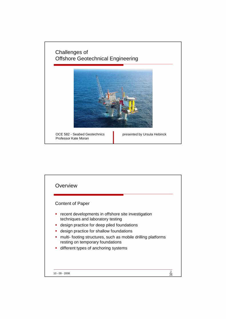
Content of Paper
� recent developments in offshore site investigation techniques and laboratory testing
� design practice for deep piled foundations� design practice for shallow foundations� multi- footing structures, such as mobile drilling platforms
resting on temporary foundations� different types of anchoring systems
225
Overview
10 - 09 - 2008
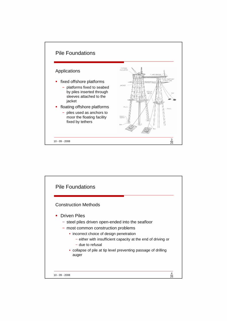
Applications
� fixed offshore platforms− platforms fixed to seabed
by piles inserted through sleeves attached to the jacket
� floating offshore platforms− piles used as anchors to
moor the floating facility fixed by tethers
325
Pile Foundations
10 - 09 - 2008
Construction Methods
� Driven Piles− steel piles driven open-ended into the seafloor− most common construction problems
• incorrect choice of design penetration
− either with insufficient capacity at the end of driving or
− due to refusal
• collapse of pile at tip level preventing passage of drilling auger
425
Pile Foundations
10 - 09 - 2008
Construction Methods
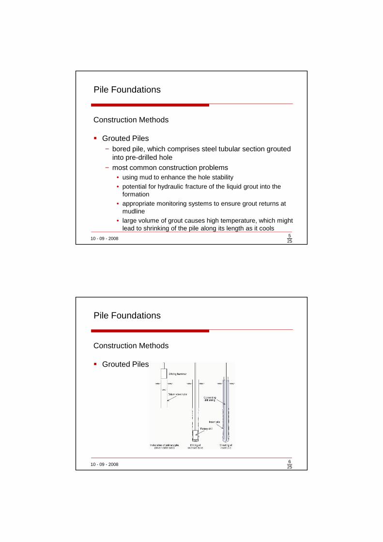
� Grouted Piles− bored pile, which comprises steel tubular section grouted
into pre-drilled hole− most common construction problems
• using mud to enhance the hole stability
• potential for hydraulic fracture of the liquid grout into the formation
• appropriate monitoring systems to ensure grout returns at mudline
• large volume of grout causes high temperature, which might lead to shrinking of the pile along its length as it cools
525
Pile Foundations
10 - 09 - 2008625
Pile Foundations
Construction Methods
� Grouted Piles
10 - 09 - 2008725
Pile Foundations
Axial Capacity
� Importance: understanding of mechanisms that determine the eventual− shaft friction and− end-bearing capacity
of different types of piles
10 - 09 - 2008825
Pile Foundations
Axial Capacity
� pile design parameters may be deduced from− for sands:
• terms of the cone resistance
− for fine-grained sediments:• undrained shear strength
• in situ vertical effective stress together with an overconsolidation ratio
10 - 09 - 2008
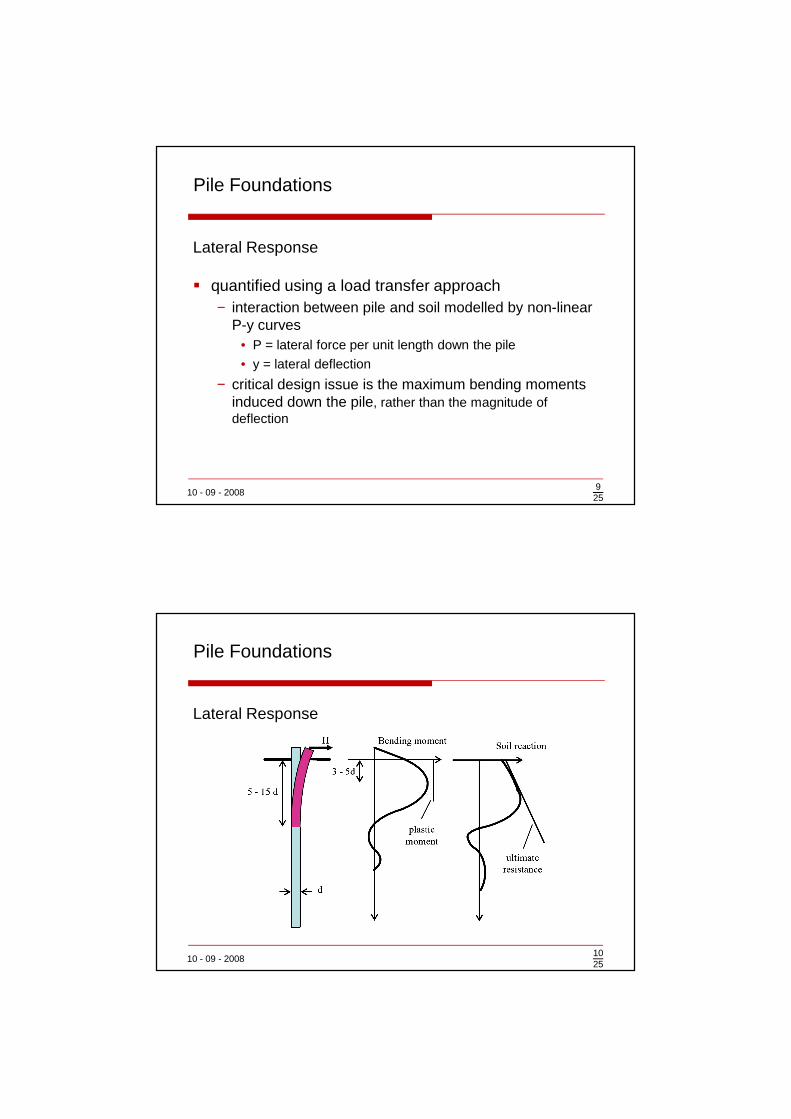
Lateral Response
� quantified using a load transfer approach− interaction between pile and soil modelled by non-linear
P-y curves• P = lateral force per unit length down the pile
• y = lateral deflection
− critical design issue is the maximum bending moments induced down the pile, rather than the magnitude of deflection
925
Pile Foundations
10 - 09 - 2008
Lateral Response
1025
Pile Foundations

10 - 09 - 2008
Applications
� historically:− large concrete gravity bases,
supporting large fixed substructures
− steel mudmats used as temporary support for conventional piled jackets before the piled foundation had been constructed
� additional nowadays:− concrete or steel bucket foundations used as anchors for
floating platforms or as permanent support for jacket structures instead of piles or as foundations for a variety of small sea bottom structures
1125
Shallow Foundations
10 - 09 - 2008
Design Features
� differences between shallow foundations onshore and offshore:− SF employed offshore are typically much larger than
those used onshore− offshore SF are required to withstand much larger
horizontal loads and overturning moments than onshore− in the design process more emphasis is placed on
capacity of offshore SF, with less emphasis on displacements than in onshore foundation design
1225
Shallow Foundations
10 - 09 - 2008
Design Features
� differences between shallow foundations onshore and offshore:− attention to cyclic loading effects on capacity is critical in
design of offshore SF− soft surface deposits offshore are incorporated into on
offshore foundation system by the provision of skirts, where onshore soft surficial soils would more often be removed prior to construction
1325
Shallow Foundations
10 - 09 - 2008
Evolution of Offshore Shallow Foundation Systems
� Concrete Gravity Bases− first gravity based platform: Ekofisk tank
− led to development of: Condeep gravity base design
− the advantage of the Condeep style platform over the Ekofisktank design is much smaller wave forces acting on the structure as the major volume of the Condeep is located deep below the water surface
1425
Shallow Foundations
10 - 09 - 2008
Evolution of Offshore Shallow Foundation Systems
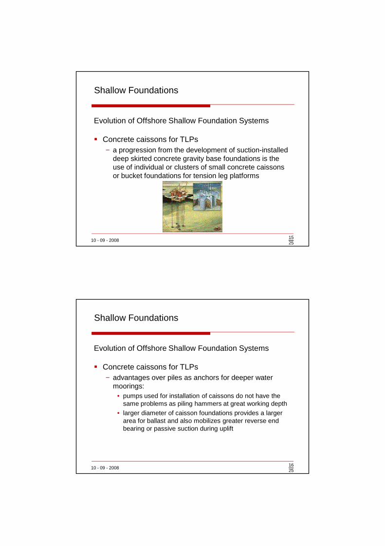
� Concrete caissons for TLPs− a progression from the development of suction-installed
deep skirted concrete gravity base foundations is the use of individual or clusters of small concrete caissons or bucket foundations for tension leg platforms
1525
Shallow Foundations
10 - 09 - 2008
Evolution of Offshore Shallow Foundation Systems
� Concrete caissons for TLPs− advantages over piles as anchors for deeper water
moorings:• pumps used for installation of caissons do not have the
same problems as piling hammers at great working depth
• larger diameter of caisson foundations provides a larger area for ballast and also mobilizes greater reverse end bearing or passive suction during uplift
1625
Shallow Foundations
10 - 09 - 2008
Evolution of Offshore Shallow Foundation Systems
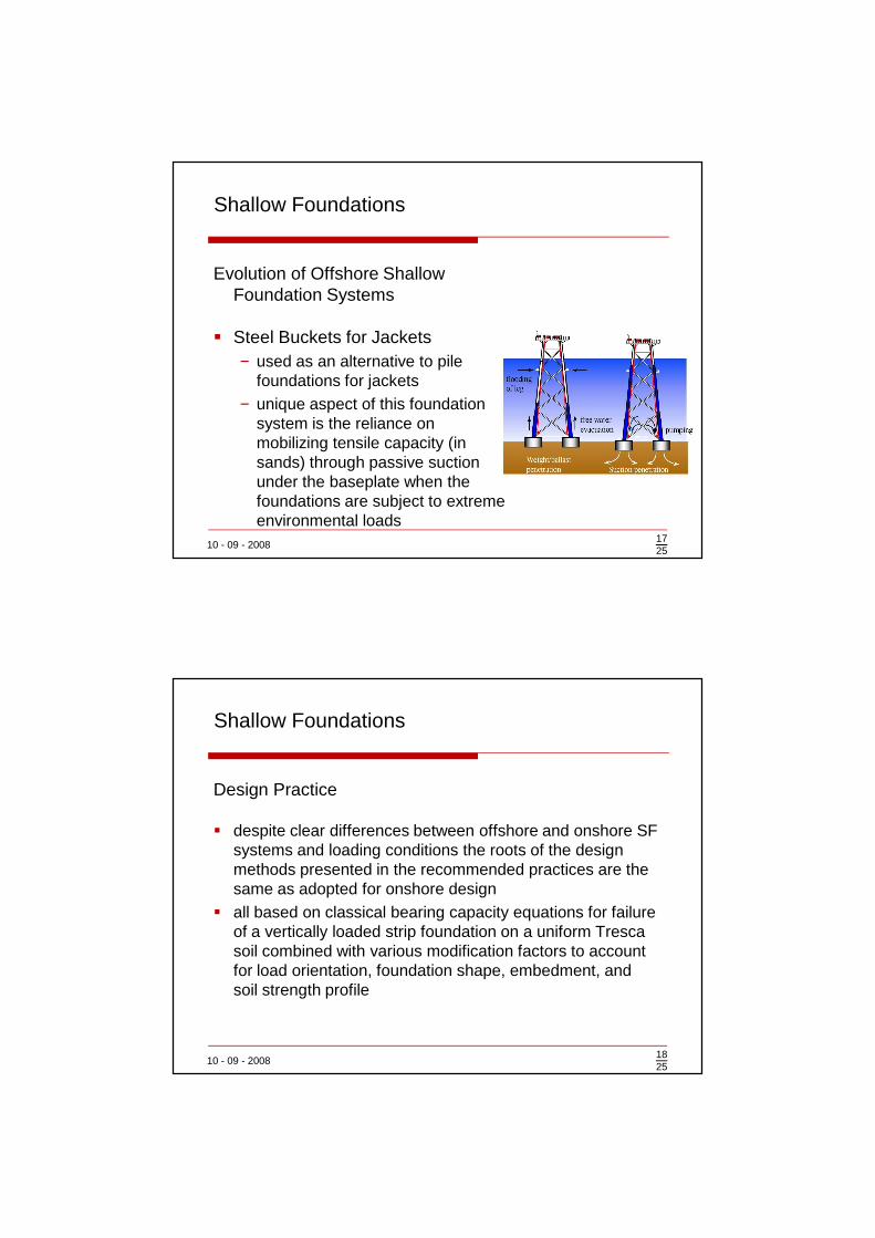
� Steel Buckets for Jackets− used as an alternative to pile
foundations for jackets− unique aspect of this foundation
system is the reliance on mobilizing tensile capacity (in sands) through passive suction under the baseplate when the foundations are subject to extreme environmental loads
1725
Shallow Foundations
10 - 09 - 2008
Design Practice
� despite clear differences between offshore and onshore SF systems and loading conditions the roots of the design methods presented in the recommended practices are the same as adopted for onshore design
� all based on classical bearing capacity equations for failure of a vertically loaded strip foundation on a uniform Trescasoil combined with various modification factors to account for load orientation, foundation shape, embedment, and soil strength profile
1825
Shallow Foundations
10 - 09 - 2008
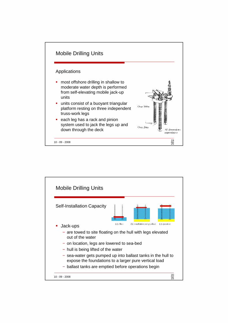
Applications
� most offshore drilling in shallow to moderate water depth is performed from self-elevating mobile jack-up units
� units consist of a buoyant triangular platform resting on three independent truss-work legs
� each leg has a rack and pinion system used to jack the legs up and down through the deck
1925
Mobile Drilling Units
10 - 09 - 2008
Self-Installation Capacity
� Jack-ups− are towed to site floating on the hull with legs elevated
out of the water− on location, legs are lowered to sea-bed− hull is being lifted of the water− sea-water gets pumped up into ballast tanks in the hull to
expose the foundations to a larger pure vertical load− ballast tanks are emptied before operations begin
2025
Mobile Drilling Units
10 - 09 - 2008
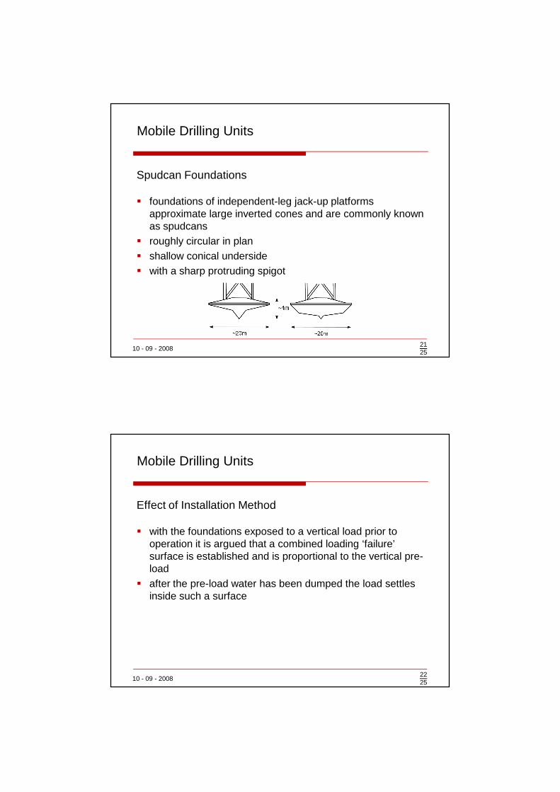
Spudcan Foundations
� foundations of independent-leg jack-up platforms approximate large inverted cones and are commonly known as spudcans
� roughly circular in plan� shallow conical underside� with a sharp protruding spigot
2125
Mobile Drilling Units
10 - 09 - 2008
Effect of Installation Method
� with the foundations exposed to a vertical load prior to operation it is argued that a combined loading ‘failure’ surface is established and is proportional to the vertical pre-load
� after the pre-load water has been dumped the load settles inside such a surface
2225
Mobile Drilling Units
10 - 09 - 2008
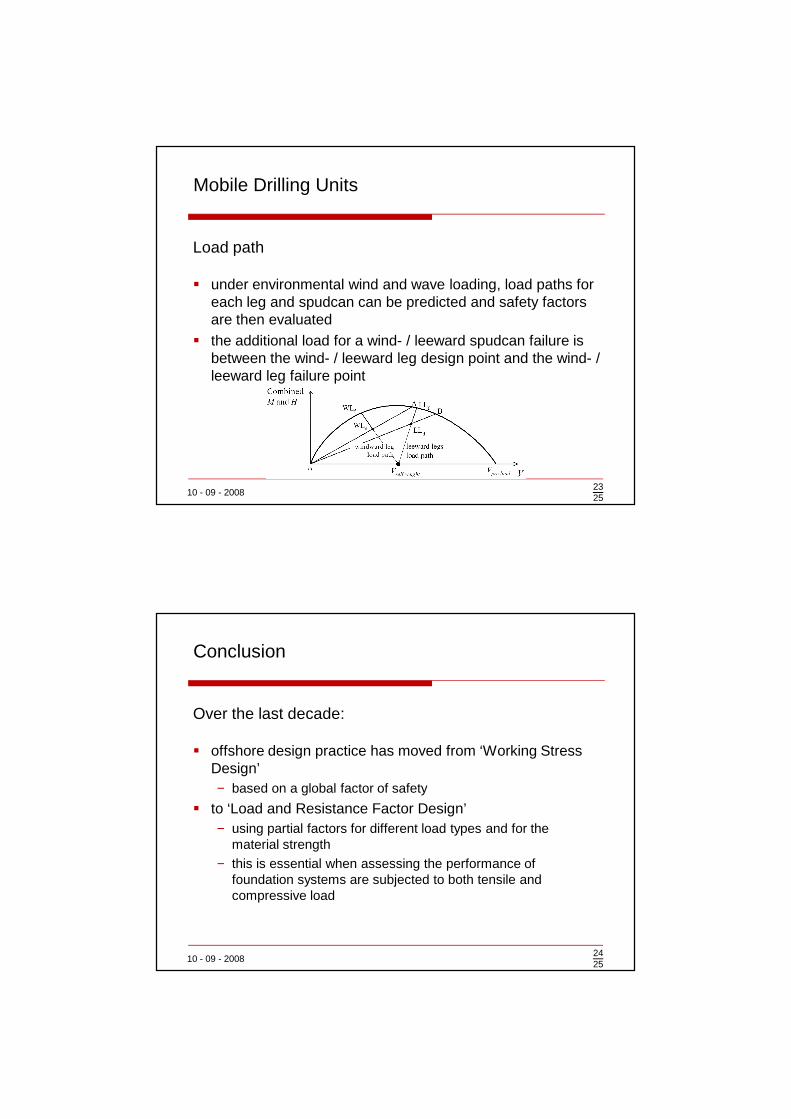
Load path
� under environmental wind and wave loading, load paths for each leg and spudcan can be predicted and safety factors are then evaluated
� the additional load for a wind- / leeward spudcan failure is between the wind- / leeward leg design point and the wind- / leeward leg failure point
2325
Mobile Drilling Units
10 - 09 - 2008
Over the last decade:
� offshore design practice has moved from ‘Working Stress Design’− based on a global factor of safety
� to ‘Load and Resistance Factor Design’− using partial factors for different load types and for the
material strength
− this is essential when assessing the performance of foundation systems are subjected to both tensile and compressive load
2425
Conclusion

10 - 09 - 20082525
THANK YOU