Chain Drive Vise - d3h1zj156zzd4j.cloudfront.neta chain drive vise to give a smooth operating double...
14
Chain Drive Vise Installation Instructions (revised 02/03/2017)
Transcript of Chain Drive Vise - d3h1zj156zzd4j.cloudfront.neta chain drive vise to give a smooth operating double...
Chain Drive ViseInstallation Instructions
(revised 02/03/2017)

3
Table of Contents
pageAbout Your Chain Drive Vise 3Parts List 4Exploded Parts Diagram 5
step 1. Prepare Your Bench Top 6step 2. Prepare Your Vise Jaw 7-8step 3. Install Vise Jaw & Screw Hardware 9-10step 4. Install T-Handle Assembly 11step 5. Mounting Stand Offs 12-13
Diagram 1. Exploded Vise Jaw Hardware Diagram 5Diagram 1A. Bench Top Specifications 6Diagram 1B. Pocket Depth Specifications 6Diagram 2A. Vise Jaw Half No. 1: Cuts & Measurements 7Diagram 2B. Vise Jaw Half No. 2: Cuts & Measurements 7Diagram 2C. Vise Jaw: Rod Hole Specifications 8Diagram 2D. Counterbore Specifications 8Diagram 3A. Exploded Rod Diagram 9
Questions?Contact us at 800-327-2520 • [email protected]
Lie-Nielsen Chain Drive Vise Instructions

3
The Lie-Nielsen Twin Screw Vise combines simplicity of design and function with heavy duty materials to create a rugged and versatile clamping system. We combined ACME threaded nuts and screws with sprockets and a chain drive vise to give a smooth operating double screw action and amazing clamping power. We believe that you will find this to be the most effective face vise available today.
When we first started making workbenches we used the best hardware that we could find, and while it was quite good we found that there was certainly room for improvement. We have since designed hardware that allows a wide board to be clamped between the screws, and that does not rack when clamping outside the screws.
About Your Chain Drive Vise
Chain Drive Vise Installation Time: Up to 12 hours (including making your own Vise Jaw and Bench prep.)
Total Travel Distance: 8 inches
An Installation Kit is available through Lie-Nielsen Toolworks for $45, returnable for credit. This kit includes the following tools:
Please call 1-800-327-2520 or visit www.lie-nielsen.com for more information.
Drills
Taps
Center Punches
Allen Wrenches
Hex Drivers
F
5/16"-18
3/8", 5/16"
1/8", 1/4"
3/16", 1/4"
IMPORTANT
• Read these instructions thoroughly before cutting into your bench and starting the installation. • Do not proceed without the vise parts and hardware in your possession.
• Always clean any rough edges or debris before proceeding to the next step.• Do not overtighten the bolts.
NOTE: This vise is designed to be installed on a 4'' thick top. The hardware can be mounted on a thicker top by ensuring all measurements for the center lines of the clearance holes in the jaw and bench are taken from the bottom. If your bench is less than 4'' thick you will require blocking and an apron to get the appropriate clamping effect.

4 5
Chain Drive Vise Parts List
Part #1Washer (8)
Part #10Cap Screws (8)
Part #11Flat Head Screws (2)
Part #12Vise Stand-Off (2)
Part #13Flange (1)
Part #14T-Handle & Screw (1)
Part #2Bearing (4)
Part #3Bronze Bushing (4)
Part #4Sprocket (2)
Part #5Sprocket Set Screw (4)(2 per sprocket)
Part #6Key (2)
Part #7Jam Nut (2)
Part #8Stop Washer & Bolt (1)
Part #9Large Stand-Off Nut (2)
Part #15Chain (1)
Part #16Vise Drive Screw (1)
Part #17Vise Screw (1)
5
Chain Drive Vise Exploded Diagram
2
2
2
2
1
11
1
10
117
6
69
3
3
4
4
13
8
12 12
14
9
3
3
115
16
17
11
10
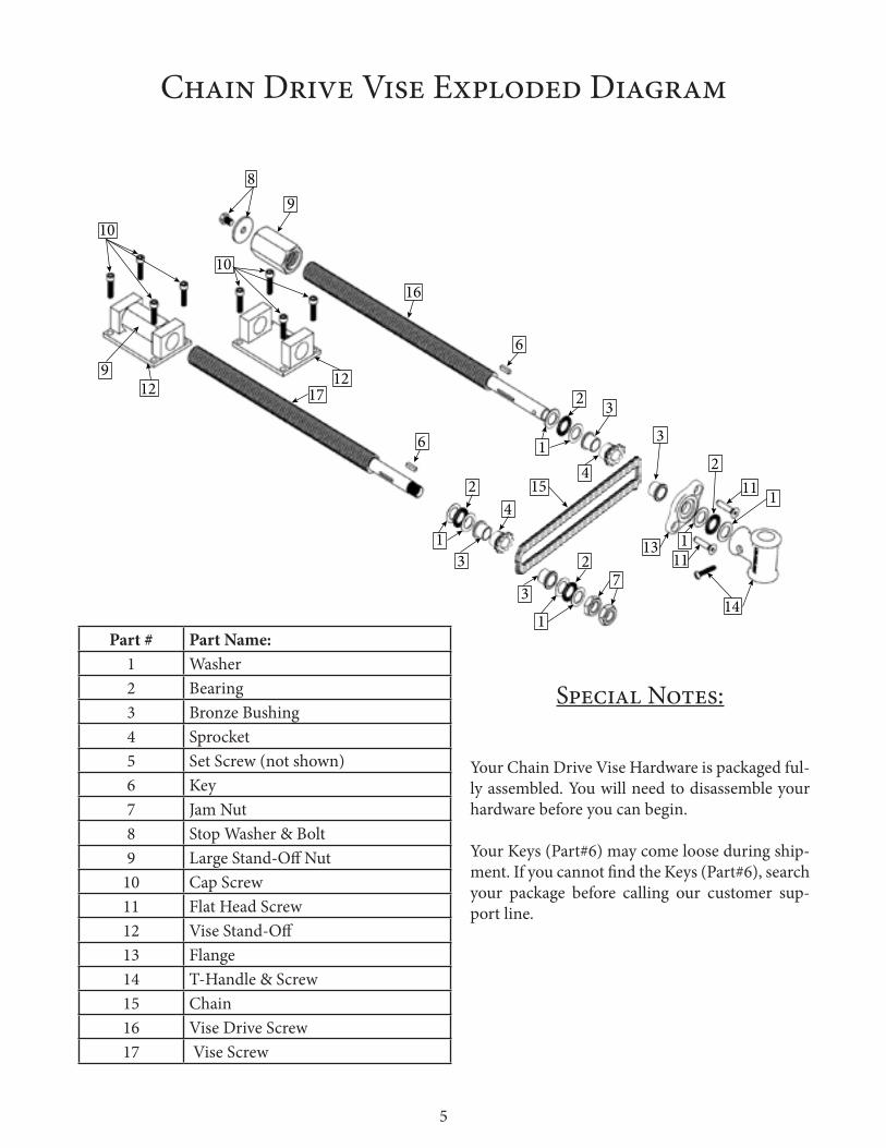
Part # Part Name:1 Washer2 Bearing3 Bronze Bushing4 Sprocket5 Set Screw (not shown)6 Key7 Jam Nut8 Stop Washer & Bolt9 Large Stand-Off Nut
10 Cap Screw11 Flat Head Screw12 Vise Stand-Off13 Flange14 T-Handle & Screw15 Chain16 Vise Drive Screw17 Vise Screw
Your Chain Drive Vise Hardware is packaged ful-ly assembled. You will need to disassemble your hardware before you can begin.
Your Keys (Part#6) may come loose during ship-ment. If you cannot find the Keys (Part#6), search your package before calling our customer sup-port line.
Special Notes:

6 7
Use Diagram 1A to make the measurements for your bench top.
To begin, determine where your first hole will be drilled on the face of your bench top.
Once you have marked the center of your first hole, use the measurements in Table 1A to de-termine the measurements for you next center mark. We recommend using a center punch to ensure the accuracy of your holes.
Next you will need to draw a center line mark off of your center marks from the face of your Bench Top to the back of your Bench Top. This will de-termine the center line for your Stand-Off 's and pockets.
Step 1: Prepare Your Bench Top
*IMPORTANT: The Measurements in Diagram 1A are based off of a 4" thick solid Bench Top.
**The measurements in the Diagram 1A are the minimal measurements needed to ensure that you will have the proper amount of space re-quired for you Chain Drive Vise Hardware to fit.
***It is very important that the holes drilled through the face of your Bench top, are square to the bottom of the bench top to ensure your Chain Drive Vise Hardware does not bind.
Diagram 1B shows the depth you need to make the pockets so the hardware fits properly. This view is looking down into the pockets, looking towards the holes in the front of the Bench Top.
Diagram 1A:
Table 1A: Center to center measurements between vise screw holes12" Chain = 13-5/16"18" Chain = 19-5/16"24" Chain = 25-5/16"
2‐1⁄4"
4‐1⁄8"
2‐1⁄2"1‐1⁄2"
1‐1⁄2"
4‐3⁄₄"
2‐1⁄2"
16"
6"
See table 1A
Diagram 1B:
Bottom of Bench Top
Top of Bench Top

7
Step 2: Prepare Your Vise Jaw
Table 2A: Vise Jaw Half Dimensions (x2)12" Chain = 22-13/16" x 4" x 1-3/8"18" Chain = 28-13/16" x 4" x 1-3/8"24" Chain = 34-13/16" x 4" x 1-3/8" Length - Width - Thickness
Table 2B: Vise Jaw Half No. 1 Dimensions12" Chain = 11-13/16"18" Chain = 17-13/16"24" Chain = 23-13/16"
Table 2C: Vise Jaw Half No. 2 Dimensions12" Chain = 16-5/16"18" Chain = 22-5/16"24" Chain = 28-5/16"
The conversions in Table 2B are the measure-ments from the inside edge to inside edge for the two pockets you will be making on Half No. 1.
Next, you will need to make the wood jaw for your vise. You will need to prepare it in two halves that will be glued together.
The conversions in Table 2C are the edge to edge measurements going left to right for the large pocket you will be making on Half No. 2
Half No. 1:
Half No. 2:
1-1⁄2"
3-1⁄4"
5⁄8"
2-3⁄4"
1-3⁄8"
See Table 2A
See Table 2A
2-3⁄4"
5⁄16"
4"
1-3/8"
See Table 2B
See Table 2C
Diagram 2A:
Diagram 2B:

8 9
Once you have finished preparing your Vise Jaw halves you will need to glue the two pieces together. Make sure that they align flush on the top side of the jaw halves. Be sure to use plenty of clamps and leave your Vise Jaw clamped together until the glue has fully dried. Next, after the vise jaw is glued and dried you will need to flatten the inside face of your vise jaw to ensure it fits flush to the face of your bench top.
Measurements For the Layout of Vise Jaw Holes
Diagram 2C:
Diagram 2D:
Table 2D: Vise Screw Holes: Center to Center Distance12" Chain = 13-5/16"18" Chain = 19-5/16"24" Chain = 25-5/16"
Your final step in preparing your vise jaw is to counter bore the holes you just marked. Do not drill all the way through your vise jaw until you have drilled your counter bores. The 7/8" hole should be the last step to prevent tear out.
Use the specifications in Diagram 2D to make your counter bores. Be sure to drill the largest hole first, and work your way down to the small-est hole. Repeat steps on all the holes of your vise jaw. Remember do not drill the 7/8" hole first. This is to prevent the risk of tearout and keep your cener mark.
Using a center punch and the measurments in Diagram 2C and Table 2D mark the center points of Vise Screw Holes.
See Table 2D
Half No. 2
Half No. 1
7/8" Diameter4-3⁄4" 1-1⁄2"
1⁄8" 1⁄8"
7⁄8"
1-1⁄8"
1-1⁄4"

9
Step 3: Install Vise Jaw & Vise Screw Hardware
3
2
1
6
Image 3A:
Image 3B:
Assemble and install the Chain (Part #15) & Sprockets (Part #4) into your vise jaw as seen in image 3A.
*IMPORTANT: When installing the Sprockets & Chain into your vise jaw, make sure the slot for the Key (Part #6) on each Sprocket is aligned to the 12 O'clock position to make installing the Threaded Rods easier.
Before you insert the vise screws into your vise jaw, make sure you have in-stalled the hardware as demonstrated in Diagram 3A. Lock these items into position by inserting the Key into the groove of the Vise Screw. Make sure the hardware is seated fully snug against the threads on the Vise Screws.
Insert the Vise Screws into the back of your vise jaw as seen in Image 3B. Make sure the Vise Screw is seated firmly into your Vise Jaw before con-tinuing.
Diagram 3A:

10 11
Install the two Jam Nuts (Part #7) onto your Vise Screw (Part #17). The first Jam Nut should be snug against the Washer but not too tight. Once the second Jam Nut is snug against the first Jam Nut, use two wrenches to tighten both Jam Nuts against each other to lock them into place.
Install the last Bronze Bushing (Part #3) on your Vise Drive Screws. Make sure they are seated fully into your vise jaw holes.
*IMPORTANT: Do not over tighten the Jam Nuts. Snug is plenty.
**When installing the Bronze Bushings we recommend using a flat tipped tools to ensure they are seated firmly into their counter bores. An allen wrench works well, one is included with your Installation Kit.
Turn your vise jaw around to install the re-maining hardware. Install a Bronze Bushing (Part #3), followed by a Washer (Part #1), followed by a Bearing (Part #2), followed by another Washer. Make sure these parts are seated firmly into your vise jaw.

11
Step 4: Install T-Handle AssemblyInstall your Flange (Part #13), followed by a Washer (Part #1), Followed by a Bearing (Part #2), and fol-lowed by another Washer.
Next using a large flat tip screwdriver, ensure your Sprockets (Part #4) are fully seated into the holes of your vise jaw assembly.
Once your Sprockets are set, tighten the 2 Set Screws (Part#5) on each Sprocket.
*IMPORTANT: Do not over tighten the screws on your T-Handle or your Flange and Set Screws.
**When tapping your Vise Jaw for the Flange Screws, we recommend using a 1/4" extension.
To install your Flat Head Screws (Part #11), you will need to use a 5/16" Center Punch and a 5/16" Tap.
First ensure the Flange is level, then use the punch to make the center marks.
Next using the F sized bit from your Installation Kit to drill a hole into your vise jaw all the way into the gap of your vise jaw.
Use the Tap to make the threads for the screws.
Use a 3/16" Hex Driver from the Installation Kit to thread the screws into the Flange.
*IMPORTANT: After installing your T-Handle & Screw (Part #14), you may find that there is a gap between your T-Handle and your Flange. If so, use the extra Washers & Bearings in your Installation Kit to fill the gap. This will prevent any play with your Chain Drive Vise.

12 13
Step 5: Mounting Stand-OffsImage 5A shows 2 pockets. Pockets A & B.
Pocket A contains your Vise Screw (Part #17) You will be securing the Stand-Off (Part #12) in Pocket A to the Bench Top first.
Pocket B will contain your Vise Drive Screw (Part #16). Leave the Stand-Off in this pocket loose.
See the formation of the Stand-Offs in Image 5A before you begin this step.
Install the vise jaw assembly into the bench top as seen in Image 5A.
Use a large vise clamp to secure the Vise Jaw assembly to your Bench Top.
In Pocket A, slide the Stand-Off firmly against the edge of the pocket closest to your vise jaw.
Use a 3/8" Center Punch to mark the four screw holes on your Stand-Off. Using a 1/4" drill bit, drill a hole 1-1/4" deep into your bench top.
Install four Stand-Off Screws using a 1/4" hex driver from your Installation Kit.
*IMPORTANT: The screws for the Stand-Offs are designed so you do not need to tap the hole you drilled during installation.
**Do not over tighten the screws on your Stand-Offs.
Image 5A:
Pocket APocket B
Pocket A
13
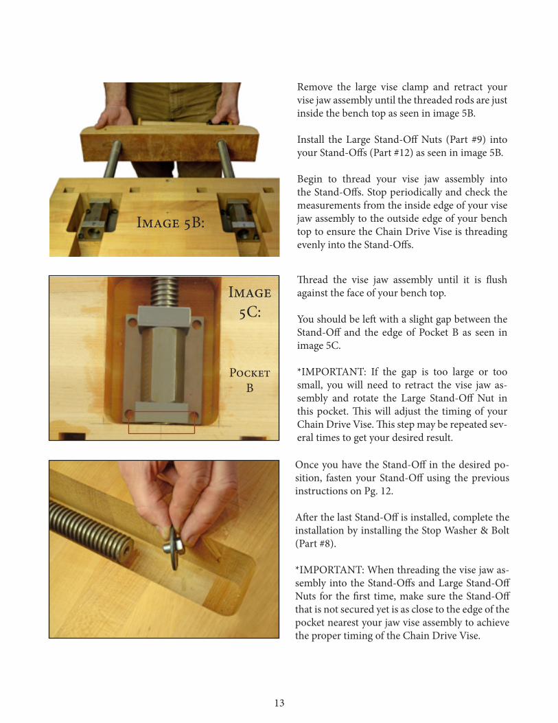
Remove the large vise clamp and retract your vise jaw assembly until the threaded rods are just inside the bench top as seen in image 5B.
Install the Large Stand-Off Nuts (Part #9) into your Stand-Offs (Part #12) as seen in image 5B.
Begin to thread your vise jaw assembly into the Stand-Offs. Stop periodically and check the measurements from the inside edge of your vise jaw assembly to the outside edge of your bench top to ensure the Chain Drive Vise is threading evenly into the Stand-Offs.
Thread the vise jaw assembly until it is flush against the face of your bench top.
You should be left with a slight gap between the Stand-Off and the edge of Pocket B as seen in image 5C.
*IMPORTANT: If the gap is too large or too small, you will need to retract the vise jaw as-sembly and rotate the Large Stand-Off Nut in this pocket. This will adjust the timing of your Chain Drive Vise. This step may be repeated sev-eral times to get your desired result.
Once you have the Stand-Off in the desired po-sition, fasten your Stand-Off using the previous instructions on Pg. 12.
After the last Stand-Off is installed, complete the installation by installing the Stop Washer & Bolt (Part #8).
*IMPORTANT: When threading the vise jaw as-sembly into the Stand-Offs and Large Stand-Off Nuts for the first time, make sure the Stand-Off that is not secured yet is as close to the edge of the pocket nearest your jaw vise assembly to achieve the proper timing of the Chain Drive Vise.
Image 5B:
Image 5C:
Pocket B

14 PB
Enjoy!!!