![Century 712/716 Formula IIIT [0500739] [04/1997] · century ® l e g e n d a r y l e a d e r s h i p owner's manual 712 / 716 wrecker & formula iiit installation, operation, maintenance](https://static.fdocuments.in/doc/165x107/5bf3f41e09d3f2de488c65ac/century-712716-formula-iiit-0500739-041997-century-l-e-g-e-n-d-a-r.jpg)
CENTURY - Miller Industries · century ® l e g e n d a r y l e a d e r s h i p owner's manual 820...
126
CENTURY® L E G E N D A R Y L E A D E R S H I P OWNER'S MANUAL 820 WRECKER / FIIIT INSTALLATION, OPERATION, MAINTENANCE & PARTS NOTE: MANUAL including SPECIFICATIONS, subject to change without notice All ratings specified are based on structural factors only, not vehicle capacities or capabilities. CENTURY® Miller Industries Towing Equipment Inc. 8503 Hilltop Drive FORM NO. 0500724 Ooltewah, Tennessee 37363 02 / 97 Phone (423) 238-4171 • FAX (423) 238-5371 PRICE $25.00
Transcript of CENTURY - Miller Industries · century ® l e g e n d a r y l e a d e r s h i p owner's manual 820...

CENTURY®
L E G E N D A R Y L E A D E R S H I P
OWNER'S MANUAL
820 WRECKER / FIIITINSTALLATION, OPERATION, MAINTENANCE & PARTS
NOTE: MANUAL including SPECIFICATIONS, subject to change without noticeAll ratings specified are based on structural factors only,
not vehicle capacities or capabilities.
CENTURY® Miller Industries Towing Equipment Inc. 8503 Hilltop Drive FORM NO. 0500724 Ooltewah, Tennessee 37363 02 / 97 Phone (423) 238-4171 • FAX (423) 238-5371 PRICE $25.00
LIMITED WARRANTY
MILLER INDUSTRIES TOWING EQUIPMENT INC., hereinafter referred to as MILLER, warrants to the original purchaser that each new MILLER wrecker or other MILLER products will be free from defects in material and workmanship for a period of twelve (12) months from date placed in service, but in no event shall such warranty period exceed twenty-four (24) months from date of manufacture by MILLER. The purchaser must promptly notify MILLER in writing of any failure in material or workmanship. In no event shall MILLER accept such notification later than twenty-four (24) months from date of delivery or twelve (12) months from date placed in service, whichever is earlier.
MILLER's obligation under this warranty, statutory or otherwise, is limited to the repair or replacement at the MILLER factory, or at a point designated by MILLER, of such part or parts as shall appear upon inspection by MILLER to be defective in material or workmanship. New or remanufactured parts will be used for any replacement at MILLER's option. This warranty is not transferable. This warranty does not obligate MILLER to bear the cost of labor or transportation charges in connection with the repair or replacement of any parts found to be defective, nor shall it apply to a product upon which repairs or alterations have been made unless authorized by MILLER.
EXCEPT AS EXPRESSLY SET FORTH IN THIS WARRANTY, MILLER MAKES NO OTHER WARRANTY, EXPRESS OR IMPLIED, AND HEREBY DISCLAIMS ALL OTHER WARRANTIES INCLUDING, BUT NOT LIMITED TO, THE IMPLIED WARRANTIES OF MERCHANTABILITY AND FITNESS FOR A PARTICULAR PURPOSE. MILLER shall in no event be liable for claimed downtime, claimed loss of profits or goodwill, or any other special, incidental, indirect, or consequential damages concerning or relating to any product or parts, whether based on negligence, strict liability, breach of contract, breach of warranty, misrepresentation or any other legal theory, regardless of whether the loss resulted from any general or particular requirement which MILLER knew or had reason to know about at the time of sale.
MILLER MAKES NO WARRANTY, EXPRESS OR IMPLIED, AS TO THE FINISHED PRODUCTS MANUFACTURED OR SUPPLIED BY ANOTHER MANUFACTURER AND SUPPLIED BY MILLER TO PURCHASER, including, but not limited to, any vehicle to which a MILLER product may be affixed or any accessories or wire rope, and MILLER EXPRESSLY DISCLAIMS ANY IMPLIED WARRANTIES OF MERCHANTABILITY OR FITNESS FOR A PARTICULAR PURPOSE AS TO SUCH EQUIPMENT OR PRODUCTS. This language shall in no way affect or diminish the rights of the purchaser to rely on such warranties as are extended by such manufacturers or suppliers. MILLER shall, to the extent permitted under applicable law, pass on to the purchaser such manufacturer's or seller's warranty.
MILLER, whose policy is one of continuous improvement, reserves the right to improve its products through changes in design or materials as it may deem desirable without being obligated to incorporate such changes in products previously sold. This warranty is not intended to cover or include the following items, which are set forth by way of example and not limitation:
A. Normal deterioration of trim, paint, lettering, and appearance items due to wear or exposure to weather, road conditions, road treatments, etc. B. Any damage or defect due to accident, misuse, abuse, improper or unauthorized repairs, failure to provide reasonable and necessary maintenance, or uses for which the equipment was not designed or intended. C. Alterations or modifications that affect performance, operation or reliability. D. Normal maintenance parts including, but not limited to, wear pads, bushings, wire rope, mud flaps, fenderettes, light bulbs, hydraulic oil, filters, and tow sling belts.
IT IS EXPRESSLY UNDERSTOOD THAT MILLER MAKES NO IMPLIED WARRANTY THAT MILLER PRODUCTS SHALL BE FIT FOR THE PURPOSE OF LIFTING OR MOVING PEOPLE OR FOR ANY OTHER IMPROPER USE.
SERIAL NUMBER Miller Industries Towing Equipment Inc. 8503 Hilltop Drive Ooltewah, Tennessee 37363
Telephone (423) 238-4171

i
OWNER, USER AND OPERATORS:
CENTURY appreciates your choice of our wrecker for your application.Our number one priority is user safety which is best achieved by ourjoint efforts. We feel that you can make a major contribution to safetyif you, as the equipment owner and operator:
1. Comply with Federal, State, and Local Regulations.
2. Read, Understand, and Follow the Instructions in this Manual.
3. Use Good, Safe Work Practices in a Common Sense Way.
4. Only have Authorized and Trained Operators running the Wrecker.
Also contained in this manual is a Parts Section for your Wrecker. Useof other than Factory or Factory Authorized Parts will render theWarranty void.
© 1997 MILLER INDUSTRIES TOWING EQUIPMENT INC. All rights reserved. Reproduction
or use, without express permission, of editorial or pictorial content, in any manner, is prohibited.

ii
TABLE OF CONTENTS
The operator must read and understandall instructions in this manualbefore operating the wrecker.
It is assumed by CENTURY that the Owner/Operator has thoroughknowledge of the accepted and lawful retrieval and towing methods asdictated by his city, county, or state. CENTURY rejects any liability claimthat may result from the incorrect or unlawful application of its equipment.
Section I - SAFETY PRECAUTIONS . . . . . . . . . . . . . . . . . . I-1 thru I-15
Section II - SPECIFICATIONS . . . . . . . . . . . . . . . . . . . . . . . II-1 thru II-6
Section III - OPERATIONAL FUNCTIONS
WRECKER . . . . . . . . . . . . . . . . . . . . . . . . . . . . . . . . . III-1 thru III-5WHEEL LIFT . . . . . . . . . . . . . . . . . . . . . . . . . . . . . . IIIA-1 thru IIIA-4
Section IV - OPERATING INSTRUCTIONS
WRECKER . . . . . . . . . . . . . . . . . . . . . . . . . . . . . . . . . IV-1 thru IV-8WHEEL LIFT . . . . . . . . . . . . . . . . . . . . . . . . . . . . . IVA-1 thru IVA-20
Section V - MAINTENANCE . . . . . . . . . . . . . . . . . . . . . . . . V-1 thru V-11
MAINTENANCE RECORD . . . . . . . . . . . . . . . . . . . . . V-7 thru V-11
Section VI - PARTS
BODY ASSEMBLY . . . . . . . . . . . . . . . . . . . . . . . . . . . . .VI-2 & VI-3FORMULA IIIT ASSEMBLY . . . . . . . . . . . . . . . . . . . . . . .VI-4 & VI-5FORMULA IIIT HYDRAULICS . . . . . . . . . . . . . . . . . . . .VI-6 & VI-7OUTER CROSSTUBE & LIFT ADAPTERS . . . . . . . . . .VI-8 & VI-9WRECKER ASSEMBLY . . . . . . . . . . . . . . . . . . . . . . . VI-10 & VI-11BOOM ELEVATION HYDRAULICS . . . . . . . . . . . . . . . . . . . . VI-12

iii
TABLE OF CONTENTS (cont'd)
Section VI - PARTS (cont'd)
BOOM EXTENSION HYDRAULICS . . . . . . . . . . . . . . . . . . . . VI-13PUMP & FILTER HYDRAULICS . . . . . . . . . . . . . . . . .VI-14 & VI-15CONTROLS & CROSSRODS . . . . . . . . . . . . . . . . . .VI-16 & VI-17WINCH ASSEMBLY . . . . . . . . . . . . . . . . . . . . . . . . . .VI-18 & VI-19BOOM END SWIVEL ASSEMBLY . . . . . . . . . . . . . . . . . . . . . VI-20HYDRAULIC CYLINDERS
WRECKER . . . . . . . . . . . . . . . . . . . . . . . . . . . . . . . . . . . VI-21FORMULA III . . . . . . . . . . . . . . . . . . . . . . . . . . .VI-22 & VI-23
REAR JACK HYDRAULICS . . . . . . . . . . . . . . . . . . . . . . . . . . VI-24WINCH MOTOR HYDRAULICS . . . . . . . . . . . . . . . . . . . . . . . VI-25LIGHTBAR ASSEMBLY . . . . . . . . . . . . . . . . . . . . . . . . . . . . . VI-26LIGHT KIT . . . . . . . . . . . . . . . . . . . . . . . . . . . . . . . . VI-27 thru VI-29GLAD HAND ASSEMBLY . . . . . . . . . . . . . . . . . . . . . . . . . . . . VI-30HEAVY DUTY TRUCK HITCH . . . . . . . . . . . . . . . . . . . . . . . . VI-31AIR OPERATED FREE SPOOL . . . . . . . . . . . . . . . . .VI-32 & VI-33KING PIN ASSEMBLY . . . . . . . . . . . . . . . . . . . . . . . . . . . . . . VI-34
Section VII - INSTALLATION . . . . . . . . . . . . . . . . . . . . . . VII-1 thru VII-9
Section VIII - SCHEMATICS
ELECTRICAL . . . . . . . . . . . . . . . . . . . . . . . . . . . . . . . . . . . . . VII-1HYDRAULIC . . . . . . . . . . . . . . . . . . . . . . . . . . . . . . . . . . . . . . VII-2

NOTES

I-1
Section I - SAFETY PRECAUTIONS
Presented in the interest of safety for all towing and recoveryunit operators.
The danger from an vehicle does not cease when it is disabledor wrecked. Recovering and towing vehicles can be dangerous,too! The danger threatens towing and recovery unit operatorsand everyone close at hand. As a towing and recovery unitoperator you must develop an awareness of the hazards involved.You must use every safeguard within reason to prevent injuries.
For each step in operating your towing and recovery unit developthe habit of asking yourself if it is safe to proceed. Carefully checkall rigging (especially snatch blocks) before starting a heavy liftor pull.
We cannot warn you of all the possible dangers you will encounter.But we will tell you of the most common hazards we know about.Learn them well.
NOTICEYou are obligated to operate yourtowing and recovery unit safely.
You can be held legally responsible forinjuries or damages resulting from
unsafe operating practices.The manufacturer's recommendationsfor operating this towing and recovery
unit can help you avoid unsafepractices and their bad consequences.These recommendations are contained
in this manual.Century is not responsible for the
results of any unsafe practice of towingand recovery unit operators.
Furthermore, the division is notresponsible for the failure of the towing
and recovery unit or its accessoriesresulting from improper maintenance.

I-2
Section I - SAFETY PRECAUTIONS (cont'd)
1.1 Improper use of this equipment can be dangerous! Incorrect operationcan result in bodily injury to the operator and bystanders. Therefore, athorough understanding of the "operating principles" and "operatinginstructions" as found in this manual is essential.
1.2 Study each job to be done. Apply common sense judgment to assuresafety to yourself and bystanders.
1.3 Plan ahead. Work safely. Avoid accidental damage and injury. If anaccident or fire does occur, react quickly with the tools and skills athand. Know how to use a first aid kit and a fire extinguisher - and whereto get assistance.
1.4 Read and understand the following instructions.
1. READ THE MOUNTING / OPERATING / MAINTENANCE MANUALFOR WARNINGS AND PRECAUTIONS.
2. NEVER TAKE ANYTHING FOR GRANTED. DON'T ASSUME THATEVERYTHING IS ALL RIGHT AT THE START OF WORK TODAY JUSTBECAUSE EVERYTHING SEEMED ALL RIGHT AT THE END OFWORK YESTERDAY. BEFORE BEGINNING OPERATION,THOROUGHLY INSPECT THE ENTIRE UNIT TO BE SURE IT IS INGOOD OPERATING CONDITION.
3. VISUALLY INSPECT THE UNIT FOR EVIDENCE OF PHYSICALDAMAGE, SUCH AS CRACKING, BENDING, OR DEFORMATION OFPLATES OR WELDS. INSPECT CAREFULLY FOR CRACKING ORFLAKING OF PAINT, WHICH MAY INDICATE A DANGEROUS CRACKIN THE STRUCTURE BENEATH. DO NOT OPERATE UNTIL REPAIRSARE MADE.
4. LOOSE OR MISSING HARDWARE, BOLTS, NUTS, AND PINSSHOULD BE PROPERLY TIGHTENED OR REPLACED WITHMANUFACTURER'S SPECIFIED HARDWARE.
5. CHECK FOR FLUID LEAKS. HYDRAULIC SYSTEM LEAKS MUSTBE CORRECTED BEFORE THE UNIT IS OPERATED. INSPECT ALLHYDRAULIC HOSES, ESPECIALLY THOSE WHICH FLEX OR
I-3
Section I - SAFETY PRECAUTIONS (cont'd)
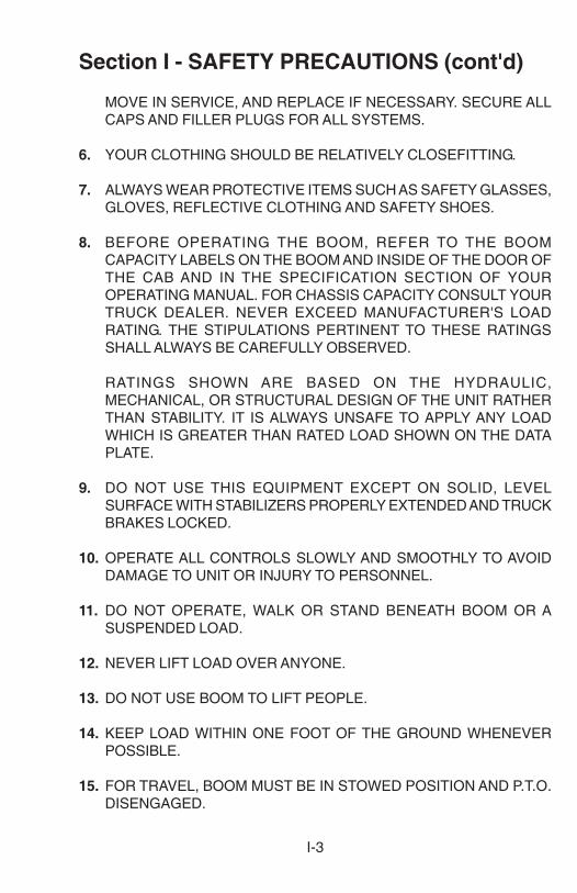
MOVE IN SERVICE, AND REPLACE IF NECESSARY. SECURE ALLCAPS AND FILLER PLUGS FOR ALL SYSTEMS.
6. YOUR CLOTHING SHOULD BE RELATIVELY CLOSEFITTING.
7. ALWAYS WEAR PROTECTIVE ITEMS SUCH AS SAFETY GLASSES,GLOVES, REFLECTIVE CLOTHING AND SAFETY SHOES.
8. BEFORE OPERATING THE BOOM, REFER TO THE BOOMCAPACITY LABELS ON THE BOOM AND INSIDE OF THE DOOR OFTHE CAB AND IN THE SPECIFICATION SECTION OF YOUROPERATING MANUAL. FOR CHASSIS CAPACITY CONSULT YOURTRUCK DEALER. NEVER EXCEED MANUFACTURER'S LOADRATING. THE STIPULATIONS PERTINENT TO THESE RATINGSSHALL ALWAYS BE CAREFULLY OBSERVED.
RATINGS SHOWN ARE BASED ON THE HYDRAULIC,MECHANICAL, OR STRUCTURAL DESIGN OF THE UNIT RATHERTHAN STABILITY. IT IS ALWAYS UNSAFE TO APPLY ANY LOADWHICH IS GREATER THAN RATED LOAD SHOWN ON THE DATAPLATE.
9. DO NOT USE THIS EQUIPMENT EXCEPT ON SOLID, LEVELSURFACE WITH STABILIZERS PROPERLY EXTENDED AND TRUCKBRAKES LOCKED.
10. OPERATE ALL CONTROLS SLOWLY AND SMOOTHLY TO AVOIDDAMAGE TO UNIT OR INJURY TO PERSONNEL.
11. DO NOT OPERATE, WALK OR STAND BENEATH BOOM OR ASUSPENDED LOAD.
12. NEVER LIFT LOAD OVER ANYONE.
13. DO NOT USE BOOM TO LIFT PEOPLE.
14. KEEP LOAD WITHIN ONE FOOT OF THE GROUND WHENEVERPOSSIBLE.
15. FOR TRAVEL, BOOM MUST BE IN STOWED POSITION AND P.T.O.DISENGAGED.

I-4
Section I - SAFETY PRECAUTIONS (cont'd)
ONLY AUTHORIZED AND TRAINED PERSONNELSHOULD BE PERMITTED TO OPERATE THIS UNIT
UNSUPERVISED.
TRAINED PERSONNEL ARE THOSE WHO HAVEWORKED UNDER EXPERIENCED SUPERVISION AND
HAVE PERFORMED ALL TOWING AND RECOVERYMANEUVERS, HAVE READ THE MOUNTING, OPERATING
AND MAINTENANCE MANUAL, WARNINGS ANDPRECAUTIONS, AND UNDERSTAND AND HAVE HAD
EXPLAINED TO THEM BY THEIR EMPLOYER THEHAZARDS OF OPERATING THE UNIT. THEY MUST BEFAMILIAR WITH THE HAZARDS OF OPERATING AT ASITE WHERE ELECTRIC POWER LINES, IRREGULARGROUND CONTOUR, WATER, ICE, MUD, OR OTHER
CONDITIONS CAN INTERFERE WITH ORDINARYCAREFUL OPERATION OF THIS UNIT.
AN UNTRAINED OPERATOR SUBJECTS HIMSELF ANDOTHERS TO DEATH OR SERIOUS INJURY.
STAND CLEARWHILE OPERATING REAR SPADES
USE SAFETY CHAINS ON ALL TOWINGAND LIFTING APPLICATIONS.

I-5
Section I - SAFETY PRECAUTIONS (cont'd)SAFETY TIPS
Death or serious injury canoccur when working near
power lines.Learn - beforehand - as
much about your workingarea as possible. Be sure
that exact locations ofoverhead power lines, and
other obstructions orhazards are known.
Don't use winch cables withhooks attached by means ofcable clips. Use only cables withhooks attached by means ofthimbles and machine swagedterminals.USE CABLE CLIPS ONLY INTHE EVENT OF ANEMERGENCY FIELDTEMPORARY REPAIR.Use at least three clips spaced3-4 inches apart and reduce thecable working limit by 20%.U-bolt of the clip should neverbe around the live or long end ofthe cable. Replace clips as soonas possible with swaged cabletermination.

I-6
Section I - SAFETY PRECAUTIONS (cont'd)SAFETY TIPS
Proper technique for using wire rope clips.USE CABLE CLIPS ONLY IN THE EVENT OF AN EMERGENCY FIELDTEMPORARY REPAIR.
RIGHTWAY
WRONGWAY
1. Turn back rope length specified in the chart. Apply first clip so U-boltis no less than the saddle width from the dead end. Tighten nuts evenlyand torque as specified.
2. Apply next clip as near loop as thimble will permit. Turn nuts on firm,but do not tighten.
3. Space additional clips as indicated so distance between clips is equal.Tighten all nuts evenly and torque as specified.
4. Apply the initial load and retighten all nuts to recommended torque.Inspect periodically and retighten as needed to the recommendedtorque.
CLIP MINIMUM AMOUNT OF ROPE TORQUESIZE NUMBER TO TURN BACK IN FT.LBS.
(INCHES) OF CLIPS IN INCHES
3/8 2 6 1/2 457/16 2 7 651/2 3 11 1/2 65
9/16 3 12 955/8 3 12 953/4 4 18 130
This table is based on Crosby-Laughlin.

I-7
Section I - SAFETY PRECAUTIONS (cont'd)SAFETY TIPS
Don't use a towing and recoveryunit that has not been properlymaintained. Pay special attention tomounting bolts, cable condition,and lubrication of moving parts.
After rigging cables, don't beginpulling without recheckingconnections. Make sure that allcables and snatch blocks aresecurely attached and cannotaccidentally pull loose.
Always use two safety chains whentowing all vehicles, regardless ofdistance.
Don't use damaged cables on theunit. Become familiar with thevarious types of cable damage andcarefully inspect all cables beingused in a recovery operation beforestarting to pull.

I-8
Section I - SAFETY PRECAUTIONS (cont'd)SAFETY TIPS
Don't expect the unit to tow loadsequal to the boom rating. Ratingsapply to loads imposed duringrecovery, with the unit properlystabilized.
Don't pull a load with the unit withoutmaking absolutely sure that thewinch drum clutch is FULLYengaged.
Don't attempt to recover heavyloads without first estimating theamount of pull that will be required.Rig to keep the estimated amountof pull well within equipment ratings.
Don't exceed ratings of booms,cables, snatch blocks, or winches.Stay within data plate ratings. Notethat boom ratings decreasesignificantly as a boom is extended.

I-9
Section I - SAFETY PRECAUTIONS (cont'd)SAFETY TIPS
Don't disengage the winch drumclutch while the winch cable isloaded.
Don't tie down the front end of theunit for recovery work or heavy lifts.You are apt to damage the truckframe if you do.
Don't exceed WORKING LIMITratings of cable. Use breakingstrength ratings only for selectingreplacement cable.
Don't get under a raised vehicle orload unless it has adequate safetyblocks in place.

I-10
Section I - SAFETY PRECAUTIONS (cont'd)SAFETY TIPS
Don't move the unit while outboardlegs or rear spades are extended.
Don't permit bystanders in the areawhile performing recovery work.
Don't use rear spades on pavedsurfaces unless you are willing toaccept responsibility for possibledamage to such surfaces.
Don't lower outboard legs or rearspades unless area under them isclear. Pay particular attention tokeeping this area clear.

I-11
Section I - SAFETY PRECAUTIONS (cont'd)SAFETY TIPS
Don't tow a vehicle that reduces theweight on the front wheels of theunit more than 50 percent.
Don’t rely on anti-theft steeringlocks. Use special steering wheelclamping device. Rope iscommonly used to secure steeringwheels, but that is not as reliableas devices designed for thispurpose.
Don’t operate the unit's enginefaster than recommended.Excessive speeds can damagePTO shafts, hydraulic pumps andwinches.
Don't completely unwind all cablefrom a winch while loaded. Keep ATLEAST five wraps on the drum.

I-12
Section I - SAFETY PRECAUTIONS (cont'd)SAFETY TIPS
Don't travel with the PTO engaged.Engage it only while operating theunit controls.
After you have hooked up a vehiclefor towing, don't start the tow untilyou have double checked the hook-up, installed safety chains andreleased the parking brakes on thetowed vehicle.
Don't use towing forks that are notof proper size for pick-uprequirements.
Don't tow a vehicle on its drivewheels unless steps have beentaken to protect its transmissionand differential. Follow therecommendations of the vehiclemanufacturer. As an alternative,use a towing dolly.

I-13
Section I - SAFETY PRECAUTIONS (cont'd)SAFETY TIPS
Don't tow a vehicle at night withoutproper signal lights on the towedvehicle and the towing unit.
Don't tow a vehicle on its frontwheels unless the steering wheelis secured with the front wheelsstraight ahead.
Don't tow a vehicle on its frontwheels if they are damaged.
After rigging cables, don’t beginpulling without recheckingconnections. Make sure that allcables and snatch blocks aresecurely attached and cannotaccidentally pull loose.

I-14
Section I - SAFETY PRECAUTIONS (cont'd)SAFETY TIPS
SAFE TOWING
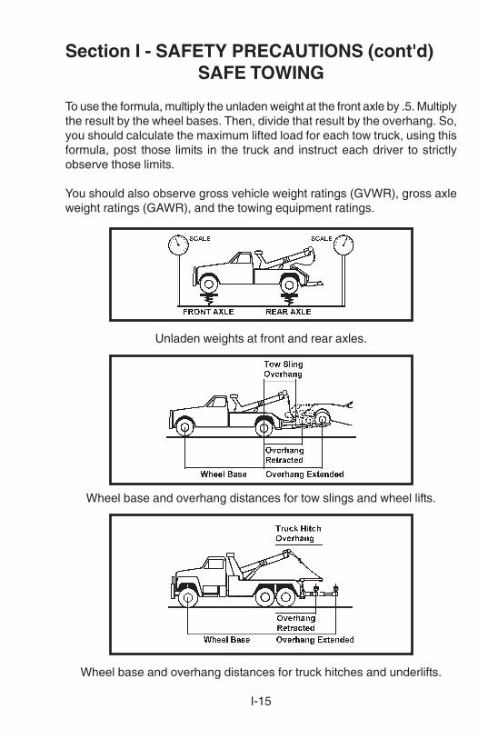
There are two key factors in safe towing:1. Have enough front axle weight for safe steering.2. Avoid excess rear axle weight.
The issue here is safety. Unsafe steering may cause a serious accident. Itis recommended that a safe steering formula that maintains at least 50percent of the UNLADEN (unloaded) front axle weight, for towing, be used.
The formula is expressed as follows: ML = .5FAW x WB/OHwhere:
ML = maximum lifted load for safe steering.FAW = unladen (unloaded) weight at front axle.WB = wheel base or distance between the center of the front axle
to the center of the rear axle(s).OH = overhang or distance from the center of the rear axle(s) to
the lift point of the towing device.
Don’t continue to wind in winchcable after the hook is against theboom end.
Don’t move unit or extend boomwhere overhead power lines maybe encountered.
I-15
Section I - SAFETY PRECAUTIONS (cont'd)SAFE TOWING
To use the formula, multiply the unladen weight at the front axle by .5. Multiplythe result by the wheel bases. Then, divide that result by the overhang. So,you should calculate the maximum lifted load for each tow truck, using thisformula, post those limits in the truck and instruct each driver to strictlyobserve those limits.
You should also observe gross vehicle weight ratings (GVWR), gross axleweight ratings (GAWR), and the towing equipment ratings.
Unladen weights at front and rear axles.
Wheel base and overhang distances for tow slings and wheel lifts.
Wheel base and overhang distances for truck hitches and underlifts.

NOTES

II-1
Section II - SPECIFICATIONS
2.1 Federal law requires that the final stage manufacturer, i.e., thatperson or company installing new equipment on a new chassis, mustcertify the completed vehicle by obtaining, completing and affixing tothe door post on the drivers side of the vehicle, a Certification Labelsimilar to the one shown. See Figure 2.1.
FIGURE 2.1

II-2
Section II - SPECIFICATIONS (cont'd)
2.2 SERIAL NUMBER / SPECIFICATION LABELS
Each Century 820 Wrecker will have a Serial Number/ SpecificationLabel mounted to the wrecker base. Also, each Century Formula IIITWheel Lift will have a Serial Number/Specification Label mounted onthe outer boom. These labels will display the Model Number, SerialNumber, Lift/Tow and Cable Ratings. See Figures 2.2 and 2.3.
FIGURE 2.2

II-3
Section II - SPECIFICATIONS (cont'd)
2.2 SERIAL NUMBER / SPECIFICATION LABELS (cont'd)
FIGURE 2.3
2.3 SPECIFICATIONS - MODEL 820 Wrecker
20-ton hydraulic wrecker with dual hydraulic winches, full power two-stage boom, 96" wide heavy-duty body for 102" C.A. single axle chassis.
(a) WinchesRating (1st Layer Each Drum) . . . . . . . . . . . . . . 20,000 lb. each
(b) CableDiameter and Length each Drum . . . . . . . . . . 9/16" dia. x 200 ft.Type: . . . . . . . . . . . . . . . . . . . . . . . . . . . 6 x 19, hemp center IPSWorking limit, each line . . . . . . . . . . . . . . . . . . . . . . . . .8,500 lbs.
(c) Wrecker Boom Specifications
BOOMLENGTH MAXIMUM MAXIMUM BOOM
BOOM CENTERLINE WORKING WORKING RATINGPOSITION PIVOT PIN TO HEIGHT DISTANCE STATIC
CENTERLINE (1) (2) (3)SHEAVE
RETRACTED 9' 8" 11' 8" 1' 10" 40,000 lbs.
EXTENDED 15' 8" 16' 3" 7' 10" 12,000 lbs.

II-4
Section II - SPECIFICATIONS (cont'd)
2.3 SPECIFICATIONS - MODEL 820 Wrecker (cont'd)
(1) At maximum boom elevation of 40 degrees above horizontal.(2) At boom angle of 1 degree above horizontal.(3) At boom angle of 10 degrees above horizontal.
Note: All ratings are based on structural factors only, not vehiclecapacities or capabilities.
2.4 SPECIFICATIONS - FORMULA IIIT Wheel Lift
Structural Rating:Extended . . . . . . . . . . . . . . . . . . . . . . . . . . . . . . . . . .10,000 lbs.Retracted . . . . . . . . . . . . . . . . . . . . . . . . . . . . . . . . . .12,000 lbs.Tow Rating (Using Lift Forks) . . . . . . . . . . . . . . . . . . .50,000 lbs.
Distance from Tailboard:Extended . . . . . . . . . . . . . . . . . . . . . . . . . . . . . . . . . . . 85 inchesRetracted . . . . . . . . . . . . . . . . . . . . . . . . . . . . . . . . . 26.5 inches
Tilt Angle:Above Horizontal (Full Up) . . . . . . . . . . . . . . . . . . . . . . . . . . .10°Below Horizontal (Full Down) . . . . . . . . . . . . . . . . . . . . . . . . .10°
"L" Bar Rating:Retracted . . . . . . . . . . . . . . . . . . . . . . . . . . . . . . . . . . .6,000 lbs.Extended . . . . . . . . . . . . . . . . . . . . . . . . . . . . . . . . . . .6,000 lbs.T.E.M.A. . . . . . . . . . . . . . . . . . . . . . . . . . . . . . . . . . . . .6,000 lbs.
2.5 CHASSIS RECOMMENDATIONS
Minimum GVWR . . . . . . . . . . . . . . . . . . . . . . . . . . . . . . . .23,500 lbs.Minimum C.A. (Cab to Axle) Dimension . . . . . . . . . . . . . . 102 inchesMinimum Frame Length (Behing Centerline of Axle) . . . 36 1/2 inches
2.6 STANDARD EQUIPMENT
• Tandem Hydraulic Pump• Winch Cable Assemblies• Dual Variable Speed Hydraulic Winches

II-5
Section II - SPECIFICATIONS (cont'd)
2.6 STANDARD EQUIPMENT (cont'd)
• 360° Directional Boom End Swivels• Dual Control Stations• Power Boom Elevation with Integral Holding Valve• Power Boom Extension• Slide Pad System• Lubrication Fittings on all Shafts and other moving parts• 96" Wide Heavy Duty Body with Flat Floor• Four Rear Tie Back Loops• Large Tunnel Tool Compartment With Door Checks• Safety Chains In Rear Pockets• Federal Standard 108 Light Group• Wiring Harness With Junction Box• PTO• Mud Flaps• Dual Winch Clutch Release• E-Z Service Hydraulic Filters• All Components for Complete Installation• Manual Rear Spades• Spade Pads
2.7 OPTIONAL EQUIPMENT
• Hydraulic Rear Spades• Additional Lifting Attachments• Air Operated Winch Clutch Release• Air Shift PTO• Cable Tensioners• Switch Panel• Medium Duty Truck Hitch• Hand-held Remote Control for Wheel Lift with Inside Cab Controls• Light Pylons• Convenience Group• Rubber Covered Front Push Bumper• Rubber Fenderettes• Tool Compartment Lights• Work Lights• Wrecker Special Light Bar• Snatch Blocks

II-6
Section II - SPECIFICATIONS (cont'd)
2.7 OPTIONAL EQUIPMENT (cont'd)
• Factory Installation• Deck Mounted Glad Hands & 7 Pin Connector
Note: Specifications Subject to Change without Notification.

III-1
Section III - OPERATIONAL FUNCTIONSWRECKER
3.1 Your new wrecker is fully hydraulic. It receives its power by means of aPower Take-Off/Pump combination mounted to the truck transmission.Since the pump is attached to the PTO, no drive line or universal jointsare required. See Figure 3.1.
FIGURE 3.1
3.2 Each function of your wrecker can be controlled from either of the DualControl Stations located at the rear of the Wrecker Body. See Figure3.2.
FIGURE 3.2

III-2
Section III - OPERATIONAL FUNCTIONSWRECKER (cont'd)
3.3 The Control Handles are clearly marked as to their functions anddirections. Movement of the control handles meters the flow of oil throughvalves to control the speed of each function.
3.4 The Vernier Throttle Control, located at the left control station, is usedto vary the speed of the truck engine to govern the maximum speed ofthe winches and cylinders. See Figure 3.3.
NOTEWITH THE ADVENT OF COMPUTERIZED ELECTRONIC
THROTTLES, VERNIER THROTTLE CONTROLS CANNOT BEUSED DUE TO THE ABSENCE OF THROTTLE LINKAGES.
CONSULT VEHICLE MANUFACTURER FORRECOMMENDATIONS.
RECOMMENDED MAXIMUM ENGINE RPM - 1400 TO 1500 RPM** ALL HYDRAULICS WILL FULLY FUNCTION AT ENGINE IDLE
FIGURE 3.3
3.5 The Wrecker Boom is elevated and extended by means of double-actinghydraulic cylinders. The boom can be elevated or extended under"LOAD" or "NO-LOAD" conditions.

III-3
Section III - OPERATIONAL FUNCTIONSWRECKER (cont'd)
3.6 The self-locking, worm-driven winch is powered by its own hydraulicmotor attached directly to the winch input shaft. See Figure 3.4.
FIGURE 3.4
3.7 Before operating your Wrecker, remove the rubber shipping plug fromthe winch vent cap. See Figure 3.5.
FIGURE 3.5

III-4
Section III - OPERATIONAL FUNCTIONSWRECKER (cont'd)
NOTECHECK OIL LEVEL IN WINCHES BEFORE ANY OPERATION.
FILL TO PROPER LEVEL WITH REQUIRED GEAR LUBRICANTAS NEEDED. REFER TO FIGURE 3.4 AND SECTION V,
MAINTENANCE FOR PROPER PROCEDURES.
3.8 Your wrecker is also equipped with Winch Free Spool Clutch Controlslocated at each winch (manual) or on either side of the wrecker body(air operated). These controls are used for allowing the winches tofreespool for payout of cable. See Figure 3.6.
FIGURE 3.6
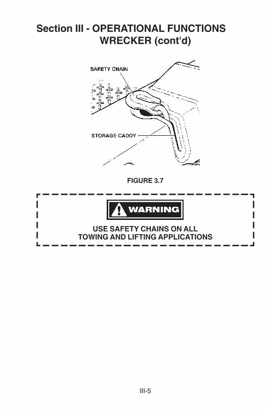
3.9 Always use Safety Chains on all towing and lifting applications. Thesafety chains are located on the top rear of the wrecker body. SeeFigure 3.7. Refer to Section 4.8 for proper safety chain procedures.
III-5
Section III - OPERATIONAL FUNCTIONSWRECKER (cont'd)
FIGURE 3.7
USE SAFETY CHAINS ON ALLTOWING AND LIFTING APPLICATIONS

NOTES

IIIA-1
Section IIIA - OPERATIONAL FUNCTIONSWHEEL LIFT
3A.1 Your new wheel lift is totally hydraulic. It receives its power from thetruck engine by means of a Power Take-Off/Pump combinationattached to the vehicle transmission. Since the pump is attacheddirectly to the PTO, no drive line or universal joints are required. Referto Figure 3.1.
3A.2 Each function of the Wheel Lift can be controlled from either of theDual Control Stations located at the rear of the wrecker body. SeeFigure 3A.1.
FIGURE 3A.1
3A.3 The Control Handles are clearly identified as to functions and directons.Movements of the control handles meters the flow of oil through valvesto control the speed of each function.
3A.4 The Wheel Lift is elevated and extended by means of double-actinghydraulic cylinders and can be operated under "LOAD" or "NO-LOAD"conditions.

IIIA-2
Section IIIA - OPERATIONAL FUNCTIONSWHEEL LIFT (cont'd)
3A.5 The Vernier Throttle Control, located at the left control station, is usedto vary the speed of the truck engine to govern the the maximumspeed of the winches and cylinders. Refer to Figure 3.3.
NOTEWITH THE ADVENT OF COMPUTERIZED ELECTRONIC
THROTTLES, VERNIER THROTTLE CONTROLS CANNOT BEUSED DUE TO THE ABSENCE OF THROTTLE LINKAGES.
CONSULT VEHICLE MANUFACTURER FORRECOMMENDATIONS.
RECOMMENDED MAXIMUM ENGINE RPM - 1400 TO 1500 RPM** ALL HYDRAULICS WILL FULLY FUNCTION AT ENGINE IDLE
3A.6 The In-Cab Control, when installed as an option, is dash mounted andcontrols the Formula III Wheel Lift. See Figure 3A.2.
FIGURE 3A.2
3A.7 The optional Hand Held Remote Control Unit electrically meters theflow of oil through valves to control each related function. The buttonsof the remote control unit are clearly marked for each function anddirection. See Figure 3A.2.

IIIA-3
Section IIIA - OPERATIONAL FUNCTIONSWHEEL LIFT (cont'd)
FIGURE 3A.3
3A.8 Lift Forks and other underlift towing accessories are located in the lefthand tool box of the wrecker body. See Figure 3A.4.
FIGURE 3A.4

IIIA-4
Section IIIA - OPERATIONAL FUNCTIONSWHEEL LIFT (cont'd)
USE SAFETY CHAINS ON ALLTOWING AND LIFTING APPLICATIONS

IV-1
Section IV - OPERATING INSTRUCTIONSWRECKER
4.1 For reasons of safety, it is important that the Owner(s) and Operator(s)should become thoroughly familiar with the controls and functions ofthe wrecker before attempting any operation.
4.2 HYDRAULIC WINCHES
The hydraulic winches are to be used in retrieving and lifting a vehiclefor transport.(a) DO NOT fasten the winch hook directly to any vehicle to be towed.(b) DO NOT wrap the winch cable around any object.(c) DO NOT exceed the working limit of the cable.(d) DO NOT use the winches or cable for the lifting of people.
4.3 PREPARING TO LOAD VEHICLE
(a) Line wrecker up with the center of disabled vehicle to be towed.
(b) Reduce truck's engine to idle and apply parking brake. Depressclutch, place transmission in neutral and engage PTO by pullingknob located on panel in cab. See Figure 4.1.
FIGURE 4.1

IV-2
Section IV - OPERATING INSTRUCTIONSWRECKER (cont'd)
4.3 PREPARING TO LOAD VEHICLE (cont'd)
NEVER DRIVE TRUCK ON STREET WITH PTO ENGAGED.THIS CAN CAUSE PUMP FAILURE DUE TO OVER-SPEED
AND OVERHEATING.
(c) Adjust engine speed to desired RPM using the Vernier ThrottleControl located on the left hand side of the wrecker body.
DO NOT EXCEED 1500 RPM
4.4 CABLE PAYOUT
Before operating any control handles, observe the winch cables to makesure they are free and have sufficient slack to allow the boom to extend.If not, payout cable by using the Cable "IN/OUT" Controls, or switch onthe Air-Operated Free Spool switch and manually pull cables out to asufficient length for boom extension. See Figure 4.2.
FIGURE 4.2

IV-3
Section IV - OPERATING INSTRUCTIONSWRECKER (cont'd)
4.5 BOOM ELEVATION
Elevate boom to the desired height by use of the Boom "UP/DOWN"Control. See Figure 4.3.
FIGURE 4.3
NOTEIN THE EVENT OF HYDRAULIC PRESSURE LOSS,
THE BOOM WILL REMAIN AT THE DESIRED ELEVATIONDUE TO THE HOLDING VALVE LOCATED IN THE BASE
OF THE LIFT CYLINDERS.
4.6 BOOM EXTENSION
Extend Boom to desired length by use of the BOOM "IN-OUT" Control.See Figure 4.4.
FIGURE 4.4

IV-4
Section IV - OPERATING INSTRUCTIONSWRECKER (cont'd)
4.7 TOWING VEHICLE WITH WRECKER
(a) After preparations have been made, back the wrecker up to vehicleuntil the tow sling makes contact with bumper. Attach "J" or "T"hook chains to vehicle and towbar. See Figure 4.5. (Refer to "TOWSLING OWNER’S MANUAL" for recommended use of towing slings.For a more particular hook up, see vehicle "OWNER'S MANUAL"or the "AAA TOWING MANUAL").
FIGURE 4.5
(b) Lift vehicle to be towed by retrieving cable slowly with use of CABLE"IN-OUT" Control. See Figure 4.6.
FIGURE 4.6

IV-5
Section IV - OPERATING INSTRUCTIONSWRECKER (cont'd)
4.7 TOWING VEHICLE WITH WRECKER (cont'd)
NOTEWHEN TOWING FROM REAR DRIVE AXLES,
PUT VEHICLE IN GEAR AND ENGAGE PARKING BRAKE.
WHEN TOWING FROM FRONT DRIVE AXLES,PUT VEHICLE IN GEAR AND DISENGAGE PARKING BRAKE.
USE SAFETY CHAINS ON ALLTOWING AND LIFTING APPLICATIONS
4.8 SAFETY CHAIN HOOK-UP PROCEDURES
(a) Extend free end of Safety Chain from storage caddy at top rear ofwrecker body. See Figure 4.7.
FIGURE 4.7

IV-6
Section IV - OPERATING INSTRUCTIONSWRECKER (cont'd)
4.8 SAFETY CHAIN HOOK-UP PROCEDURES (cont'd)
(b) Route free end of chain to vehicle to be towed and attach to chassisaround axle, leaf springs, frame or "A" frame. See Figures 4.8 thru4.11.
FIGURE 4.8 AXLE HOOK-UP
FIGURE 4.9 LEAF SPRING HOOK-UP

IV-7
Section IV - OPERATING INSTRUCTIONSWRECKER (cont'd)
4.8 SAFETY CHAIN HOOK-UP PROCEDURES (cont'd)
FIGURE 4.10 FRAME HOOK-UP
FIGURE 4.11 A-FRAME HOOK-UP
(c) Pull excess chain back to storage caddy. While holding chainsecurely, feed any excess chain back into storage caddy untilenough slack is left in chain for sharp turns.

IV-8
Section IV - OPERATING INSTRUCTIONSWRECKER (cont'd)
4.8 SAFETY CHAIN HOOK-UP PROCEDURES (cont'd)
SAFETY CHAIN MUST BE SEATED IN BOTTOM OF SLOTBEFORE ATTEMPTING TO TOW VEHICLE.
SEE FIGURE 4A.12.
FIGURE 4.12

IVA-1
Section IVA - OPERATING INSTRUCTIONSWHEEL LIFT
4A.1 For reasons of safety, it is important that the Owner/Operator(s) ofthe Wheel Lift become thoroughly familiar with its controls,components and load requirements before attempting any operation.
4A.2 CONTROLS
The Control Levers are located at the rear of the body on both theleft and right sides. All the controls are clearly identified as to theirfunction and direction. Refer to Figure 3A.1.
4A.3 PREPARING TO LOAD VEHICLE
(a) Line the Wheel Lift up with the center of disabled vehicle to betowed. See Figure 4A.1.
FIGURE 4A.1
(b) Reduce truck's engine to an idle and apply parking brake.Depress clutch, place transmission in neutral and engage PTOby pulling out knob located on the dash panel in truck cab. Referto Figure 4.1.
NEVER DRIVE TRUCK ON STREET WITH PTO ENGAGED.THIS CAN CAUSE PUMP FAILURE DUE TO OVER-SPEED
AND OVERHEATING.

IVA-2
Section IVA- OPERATING INSTRUCTIONSWHEEL LIFT (cont'd)
4A.3 PREPARING TO LOAD VEHICLE (cont'd)
(c) Adjust engine speed to desired RPM using the Vernier ThrottleControl located on the left hand side of the wrecker body.
DO NOT EXCEED 1500 RPM
4A.4 WHEEL LIFT TOWING PREPARATION
(a) Loosen "T" handle and extend outer crosstube until the tirerestraint retainers are just beyond the outer sidewall of tires onthe vehicle to be towed. See Figure 4A.2.
FIGURE 4A.2
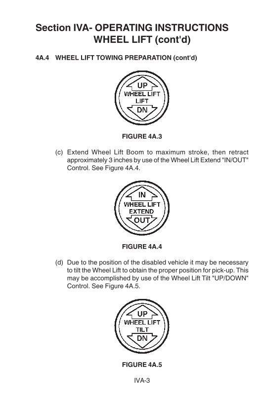
(b) Lower Wheel Lift to ground, then raise until Wheel Lift just clearsground level by use of the Wheel Lift Lift "UP/DOWN" Control.See Figure 4A.3.
IVA-3
Section IVA- OPERATING INSTRUCTIONSWHEEL LIFT (cont'd)
4A.4 WHEEL LIFT TOWING PREPARATION (cont'd)
FIGURE 4A.3
(c) Extend Wheel Lift Boom to maximum stroke, then retractapproximately 3 inches by use of the Wheel Lift Extend "IN/OUT"Control. See Figure 4A.4.
FIGURE 4A.4
(d) Due to the position of the disabled vehicle it may be necessaryto tilt the Wheel Lift to obtain the proper position for pick-up. Thismay be accomplished by use of the Wheel Lift Tilt "UP/DOWN"Control. See Figure 4A.5.
FIGURE 4A.5

IVA-4
Section IVA - OPERATING INSTRUCTIONSWHEEL LIFT (cont'd)
4A.5 VEHICLE HOOK-UP
(a) After all preparations have been made as illustrated, back theWheel Lift until the crosstubes are firmly against the tires of thevehicle to be towed. Take the truck out of gear and apply parkingbrake.
(b) Lower Wheel Lift to ground and extend boom until it is firmlyagainst tires of disabled vehicle. See Figure 4A.6.
FIGURE 4A.6
(c) Disengage the tire restraint Plunger by pulling out and rotating90°. See Figure 4A.7.

IVA-5
Section IVA - OPERATING INSTRUCTIONSWHEEL LIFT (cont'd)
4A.5 VEHICLE HOOK-UP (cont'd)
FIGURE 4A.7
(d) Insert Tire Restraint into crosstube until it is firmly against therear of the tire. See Figure 4A.8.
FIGURE 4A.8

IVA-6
Section IVA- OPERATING INSTRUCTIONSWHEEL LIFT (cont'd)
4A.5 VEHICLE HOOK UP (cont'd)
(e) Engage Plunger and adjust the tire restraint until the plungerengages in the appropriate hole in the tire restraint.
NOTEWITH TIRE RESTRAINTS INSTALLED, BE CERTAIN THAT ITWILL CAUSE NO DAMAGE TO THE VEHICLE TO BE TOWED
WHEN UNDERLIFT IS IN ITS RAISED POSITION.
TO AVOID ANY DAMAGE FROM TIRE RESTRAINTS,ADJUST CROSSTUBES TO DESIRED POSITION.
(f) Repeat procedures (c) through (e) on opposite side of vehicle.
(g) Take vehicle out of gear and make certain parking brake is off.
(h) Using the Wheel Lift Lift "UP/DOWN" Control raise the vehicleto desired towing height.
4A.6 SECURING VEHICLE TO BE TOWED
(a) Release Safety Strap Ratchet by releasing lock on Ratchet LockHandle. See Figure 4A.9.

IVA-7
Section IVA- OPERATING INSTRUCTIONSWHEEL LIFT (cont'd)
4A.6 SECURING VEHICLE TO BE TOWED (cont'd)
FIGURE 4A.9
(b) With Ratchet Lock released, pull handle all the way up and pullout the desired length of Safety Strap.
(c) Position Safety Strap over top of tire as shown in Figure 4A.10.Make certain that the round portion of the "D"-Ring is towardsthe Wheel Lift.

IVA-8
Section IVA- OPERATING INSTRUCTIONSWHEEL LIFT (cont'd)
4A.6 SECURING VEHICLE TO BE TOWED (cont'd)
FIGURE 4A.10
NOTEIF TOWING A TRUCK, OR A VEHICLE WITH LARGER THAN 15"TIRES, IT WILL BE NECESSARY TO USE THE SAFETY STRAP
EXTENSION THAT IS PROVIDED. SEE FIGURE 4A.11 FORAPPLICATION METHOD.

IVA-9
Section IVA- OPERATING INSTRUCTIONSWHEEL LIFT (cont'd)
4A.6 SECURING VEHICLE TO BE TOWED (cont'd)
FIGURE 4A.11
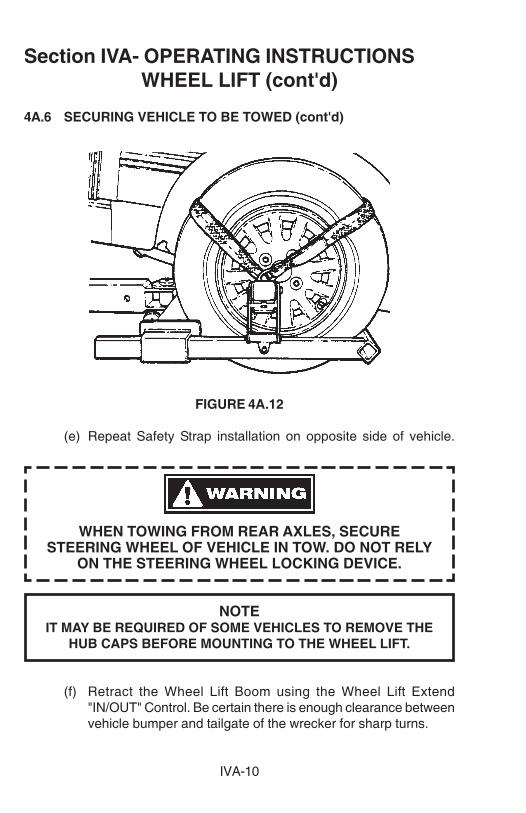
(d) Release Ratchet Lock and tighten Safety Strap around tiresecurely with ratchet. See Figure 4A.12.
IVA-10
Section IVA- OPERATING INSTRUCTIONSWHEEL LIFT (cont'd)
4A.6 SECURING VEHICLE TO BE TOWED (cont'd)
FIGURE 4A.12
(e) Repeat Safety Strap installation on opposite side of vehicle.
WHEN TOWING FROM REAR AXLES, SECURESTEERING WHEEL OF VEHICLE IN TOW. DO NOT RELY
ON THE STEERING WHEEL LOCKING DEVICE.
NOTEIT MAY BE REQUIRED OF SOME VEHICLES TO REMOVE THE
HUB CAPS BEFORE MOUNTING TO THE WHEEL LIFT.
(f) Retract the Wheel Lift Boom using the Wheel Lift Extend"IN/OUT" Control. Be certain there is enough clearance betweenvehicle bumper and tailgate of the wrecker for sharp turns.

IVA-11
Section IVA- OPERATING INSTRUCTIONSWHEEL LIFT (cont'd)
4A.6 SECURING VEHICLE TO BE TOWED (cont'd)
NOTEWHEN TOWING FROM REAR DRIVE AXLES,
PUT VEHICLE IN GEAR AND ENGAGE PARKING BRAKE.
WHEN TOWING FROM FRONT DRIVE AXLES,PUT VEHICLE IN GEAR AND DISENGAGE PARKING BRAKE.
NOTETHE CLOSER TO THE TAILGATE OF THE WRECKER A
VEHICLE IS TOWED, THE MORE FRONT END WEIGHT WILLBE AVAILABLE FOR STEERING DURING TOW.
4A.7 SAFETY CHECK PROCEDURES
(a) In the event of a sudden stop, follow the procedures below forreasons of safety in towing.
1. Pull off road and check Safety Straps to make certain theyare tight and secure.
2. Should the safety straps be loose, lower Wheel Lift to theground allowing the tires to re-align themselves in thecrossbars. Raise the Wheel Lift to desired towing height andtighten the safety straps securely with the Safety StrapRatchet.
4A.8 UNLOADING TOWED VEHICLE
(a) Reverse steps 4A.5 through 4A.6.
4A.9 HOOK-UP FOR VEHICLE WITH FLAT TIRE(S)
(a) Loosen "T" Handle and extend outer crosstubes until tire restraintretainers are just beyond the outer sidewalls of tires on disabledvehicle. Refer to Figure 4A.2.

IVA-12
Section IVA- OPERATING INSTRUCTIONSWHEEL LIFT (cont'd)
4A.9 HOOK-UP FOR VEHICLE WITH FLAT TIRE(S) (cont'd)
(b) Lower Wheel Lift to ground then raise until Wheel Lift just clearsground level.
(c) Fully extended Wheel Lift Boom, then retract approximately 3inches.
(d) After all preparations are complete, back the Wheel Lift up untilthe crossbars are firmly against the tires of the disabled vehicle.
NOTEMAKE CERTAIN THE TRANSMISSION IS IN GEAR (PARK)
AND THE PARKING BRAKE IS ENGAGEDON THE DISABLED VEHICLE BEFORE
THE WHEEL LIFT CROSSBAR IS ENGAGED.
(e) Should only one tire be flat, secure the inflated tire in normalfashion. Refer to 4A.5 and 4A.6.
(f) Extend the Wheel Lift Boom as far as possible against the flattire(s). This should allow the crossbar to compress the tirecompletely. See Figure 4A.13.
FIGURE 4A.13

IVA-13
Section IVA - OPERATING INSTRUCTIONSWHEEL LIFT (cont'd)
4A.9 HOOK-UP FOR VEHICLE WITH FLAT TIRE(S) (cont'd)
(g) Install tire restraint onto flat tire. See Figure 4A.14.
FIGURE 4A.14
(h) Place transmission in neutral and disengage parking brake ondisabled vehicle.
(i) Raise the vehicle and place blocks on timbers beneath the flattire. Lower the Wheel Lift allowing the tire to rest on the blocking.
(j) Engage parking brake and place transmission in gear (park) ofthe disabled vehicle.
(k) Extend Wheel Lift further, allowing the crossbar to compress thetire further. Re-adjust Tire Restraint as far as possible into theflat tire. This ensures the rim of the wheel will rest on the crossbarand tire restraint.
(l) Raise Wheel Lift and remove blocking from beneath the tire.
(m) Install Safety Strap on flat tire. Refer to Section 4A.7, SECURINGVEHICLE TO BE TOWED.

IVA-14
Section IVA - OPERATING INSTRUCTIONSWHEEL LIFT (cont'd)
4A.9 HOOK-UP FOR VEHICLE WITH FLAT TIRE(S) (cont'd)
(n) When tightening Safety Strap around a flat tire be certain it hasthe tire completely collapsed. This ensures proper installation ofthe strap on a flat tire. See Figure 4A.15.
FIGURE 4A.15
4A.10 OUTER CROSS TUBE REMOVAL
(a) Loosen "T" Handles and fully extend Outer Cross Tubes.
(b) Insert a screwdriver or 1/4" rod into Stop Rod Hole located beside"T" Handle. See Figure 4A.16.

IVA-15
Section IVA - OPERATING INSTRUCTIONSWHEEL LIFT (cont'd)
4A.10 OUTER CROSS TUBE REMOVAL (cont'd)
(a) Loosen "T" Handles and fully extend Outer Cross Tubes.
(b) Insert a screwdriver or 1/4" rod into Stop Rod Hole located beside
FIGURE 4A.16
(c) While pushing in to release Stop Rod, pull outer crosstube offthe crossbar. To reinstall outer crosstubes, simply slide themonto the crossbar. The Stop Rod will automatically engage whenslid all the way on. Tighten "T" Handles.
4A.11 TOW FORK ADAPTERS
(a) Remove outer crosstubes.
(b) Loosen "T" Handles on Fork Adapters and slide onto crossbar.See Figure 4A.17.

IVA-16
Section IVA - OPERATING INSTRUCTIONSWHEEL LIFT (cont'd)
4A.11 TOW FORK ADAPTERS (cont'd)
FIGURE 4A.17
NOTETHE FORK ADAPTERS CAN BE PLACED IN ANY OF FOUR (4)POSITIONS AND ANY LOCATION ON THE CROSSBAR. SEE
FIGURE 4A.18.

IVA-17
Section IVA - OPERATING INSTRUCTIONSWHEEL LIFT (cont'd)
4A.11 TOW FORK ADAPTERS (cont'd)
FIGURE 4A.18
4A.12 TOW FORK & ADAPTER APPLICATIONS
(a) Align Wheel Lift with disabled vehicle.
NOTESTEPS (b) THROUGH (d) ARE NOT NECESSARY
PROVIDED THE AXLE IS HIGH ENOUGH TO ALLOWEXTENSION OF BOOM WITH FORKS AND ADAPTERS
INSTALLED ON CROSSBAR.
(b) Extend the Boom (without adapters or forks) until crossbar iscentered with axle of disabled vehicle.
(c) Raise vehicle until tire can be blocked up high enough to allowforks to clear axle when installed onto the crossbar.

IVA-18
Section IVA - OPERATING INSTRUCTIONSWHEEL LIFT (cont'd)
4A.12 TOW FORK & ADAPTER APPLICATIONS (cont'd)
(d) Block up tires and lower Boom until boom can be retracted forinstallation of adapters and forks.
(e) Install adapters in desired configuration on crossbar. Select andinstall desired forks into adapters.
(f) Extend Boom until Forks are beneath axle or frame as desired.
(g) Manually adjust adapters on crossbar to a point where the forkswill come in contact with the frame or axle in the desired towingposition.
(h) Tighten "T" Handles on adapters. Attach safety chains aroundaxle or frame, crossbar and forks as shown in Figure 4A.19.
FIGURE 4A.19

IVA-19
Section IVA - OPERATING INSTRUCTIONSWHEEL LIFT (cont'd)
4A.12 TOW FORK & ADAPTER APPLICATIONS (cont'd)
USE SAFETY CHAINS ON ALLTOWING AND LIFTING APPLICATIONS
(i) Raise vehicle to desired height for towing.
(j) Remove any blocks previously placed under the tires.
(k) Retract Boom pulling disabled vehicle as close to the Wheel Liftbody as possible while maintaining enough distance for sharpturns.
(l) Raise Boom to desired towing height.
(m) Pull excess Safety Chain back into Storage Caddy. Be certain toallow enough slack for sharp turns.
SAFETY CHAIN MUST BE SEATED IN BOTTOM OF SLOTBEFORE ATTEMPTING TO TOW VEHICLE.
SEE FIGURE 4A.20.

IVA-20
Section IV - OPERATING INSTRUCTIONSWHEEL LIFT (cont'd)
4A.12 TOW FORK & ADAPTER APPLICATIONS (cont'd)
FIGURE 4A.20
V-1
Section V - MAINTENANCE
5.1 The continued operation of your Century Wrecker is largely dependentupon strict adherence to a properly scheduled preventive maintenanceprogram. To help you in this program, the manufacturer has providedthe following information regarding lubrication, preventive maintenanceand hydraulic system care.
5.2 HYDRAULIC SYSTEM
The importance of absolute cleanliness of the hydraulic system cannotbe over-stressed. The smallest amount of grit, metal flake or other foreignmaterial in the system can cause extensive damage to pumps, motorsand valves. The manufacturer has taken every measure to assure thateach component and fitting was thoroughly cleaned before your unitwas shipped to you. Therefore, servicing of the system should be donewith extreme care.
(a) Before checking oil level in reservoir, wipe away all dirt, grease andgrime around filler cap before removing it. Make certain that allcontainers, funnels and pouring spouts are absolutely clean beforefilling reservoir.
(b) When replacing hoses, fittings or other components, cleanthoroughly; then assemble carefully.
(c) Failure to observe these precautions, and failure to change the filterelement at regular intervals could result in loss of your warranty inthe event of failure of certain components.
5.3 LUBRICATION & PREVENTIVE MAINTENANCE
The following general lubrication and preventive maintenance shouldbe performed at least once per month for moderate usage or moreoften as required, for heavy usage.
(a) Inspect, repair or replace any worn, cracked, leaking, otherwisedamaged components including, but not limited to, the following:
1. Hydraulic Oil Filter2. Oil Reservoir3. Controls4. Cables and Fittings
V-2
Section V - MAINTENANCE (cont'd)
5.3 LUBRICATION & PREVENTIVE MAINTENANCE (cont'd)
5. Hydraulic Hoses and Fittings6. Lights and Wiring7. Winches8. Pivot Bearing Surfaces and Pins
(See Lubrication Charts, page V-5 & V-6.)
(b) Check hydraulic oil level in reservoir and fill to proper level. Refer to5.4, SUMMARY OF REQUIRED LUBRICANTS for recommendedoils to use.
(c) Replace hydraulic oil filters after first week of operation, then everythree (3) months thereafter.
(d) Inspect all bolts for tightness and re-tighten as necessary. Vibrationand stress may loosen even properly torqued bolts.
(e) Lubricate all grease fittings on the Wrecker and Wheel Lift weeklyincluding:
1. Bellcranks and Control Handle Shafts2. Winch3. Cables4. Cylinder Pivot Bearings5. Cross Bar Pivot6. Boom and Wheel Lift Slide Pads7. Boom End Swivels
(f) All bearing surfaces not equipped with grease fittings should beoiled using SAE 30 oil in a pump can.
(g) Check oil level of winches and fill to proper level, level plug on endplates. Use SAE 140 general purpose gear oil.
(h) Lubricate grease fitting on winch freespool clutch control.
(i) Lubricate winch cables using an oily rag while respooling onto drum.Other special cable lubricants are available which have betterpenetrating qualities. Consult your local oil company for a list ofthese.

V-3
Section V - MAINTENANCE (cont'd)
5.4 SUMMARY OF REQUIRED LUBRICANTS
(a) Hydraulic Oil
Examples:1. Texaco - Rando HD 462. Shell - Tellus Oil 463. Mobil - Nuto H46
or Equal
(b) Winch Worm Gear Oil - SAE 140 general purpose gear oil.
Examples:1. Humble - Pen-O-Led EP #52. Phillips - Phillips Worm Gear Oil 1403. Shell - Macona #9784. Sinclair - Pennant EP #65. Standard - Stanogear #56. Texaco - Maropa #5
(c) Grease - Synthetic Fortified Grease such as Drydene SFG orequivalent.
(d) Oil for miscellaneous bearing surfaces - SAE 30.
(e) Cable Oil - SAE 30 or special cable lubricant.
NOTETHERE IS NO PRACTICAL WAY TO DETERMINE THE LIFE
EXPECTANCY OF HYDRAULIC HOSES AND OTHER RUBBERCOMPONENTS.
WHILE APPEARING TO BE IN EXCELLENT CONDITION, THESECOMPONENTS MAY BE ADVERSELY AFFECTED BY USAGE,
WEATHER OR THE PASSING OF TIME.
THEREFORE, IT IS RECOMMENDED THAT ALL RUBBERCOMPONENTS, ESPECIALLY HOSES, BE REPLACED EVERY
FIVE (5) YEARS REGARDLESS OF APPEARANCE.

V-4
Section V - MAINTENANCE (cont'd)
5.5 CARE OF HYDRAULICS IN COLD CLIMATES
Regions subject to continuous sub-zero or arctic climates require specialhydraulic fluids. Contact Holmes or your local supplier for informationregarding specific temperature requirements.

V-5
Section V - MAINTENANCE (cont'd)
LUBRICATION CHART - WRECKER
1. Control Handle Shafts - synthetic fortified grease.2. Cable - oily rag or approved cable lubricant.3. Winches - SAE 140 gear oil to proper level.4. Cylinder Pivot Bearings - synthetic fortified grease.5. Winch Freespool - synthetic fortified grease.6. Hydraulic Reservoir - approved hydraulic fluid to proper level.7. Hydraulic Filter - Replace after first week, then every three (3)
months.8. Boom End Swivels - synthetic fortified grease.9. Sheaves - synthetic fortified grease.
10. Extend / Lift Cylinders - synthetic fortified grease.11. Boom Slide Pads - synthetic fortified grease.12. Tool Compartment Door Hinges - use SAE 30 Oil.
NOTETHE ABOVE SERVICE REQUIREMENTS
SHOULD BE SERVICED MONTHLY.
SERVICE MORE OFTEN IF THE EQUIPMENTIS USED FREQUENTLY.

V-6
Section V - MAINTENANCE (cont'd)
LUBRICATION CHART - WHEEL LIFT
1. Lift Cylinder Pivot Bearings - synthetic fortified grease.2. Upper Arm Assembly - synthetic fortified grease.3. Tilt Cylinder - synthetic fortified grease.4. Wheel Lift Outer Boom - synthetic fortified grease.
Wheel Lift Inner Boom - synthetic fortified grease.5. Wheel Lift Pivot Pin - synthetic fortified grease.6. Tire Restraint Plunger - synthetic fortified grease.
NOTETHE ABOVE SERVICE REQUIREMENTS
SHOULD BE SERVICED MONTHLY.
SERVICE MORE OFTEN IF THE EQUIPMENTIS USED FREQUENTLY.

V-7
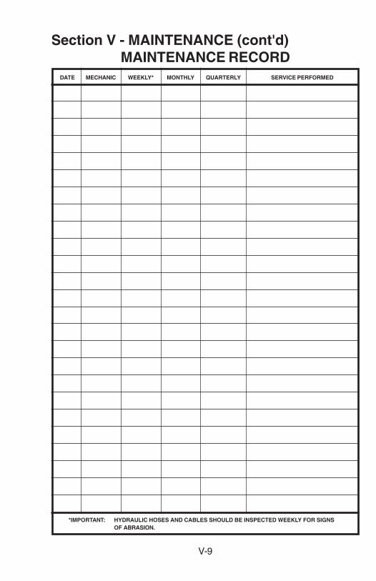
Section V - MAINTENANCE (cont'd)MAINTENANCE RECORD
DATE MECHANIC WEEKLY* MONTHLY QUARTERLY SERVICE PERFORMED
*IMPORTANT: HYDRAULIC HOSES AND CABLES SHOULD BE INSPECTED WEEKLY FOR SIGNSOF ABRASION.

V-8
Section V - MAINTENANCE (cont'd)MAINTENANCE RECORD
DATE MECHANIC WEEKLY* MONTHLY QUARTERLY SERVICE PERFORMED
*IMPORTANT: HYDRAULIC HOSES AND CABLES SHOULD BE INSPECTED WEEKLY FOR SIGNSOF ABRASION.
V-9
Section V - MAINTENANCE (cont'd)MAINTENANCE RECORD
DATE MECHANIC WEEKLY* MONTHLY QUARTERLY SERVICE PERFORMED
*IMPORTANT: HYDRAULIC HOSES AND CABLES SHOULD BE INSPECTED WEEKLY FOR SIGNSOF ABRASION.

V-10
Section V - MAINTENANCE (cont'd)MAINTENANCE RECORD
DATE MECHANIC WEEKLY* MONTHLY QUARTERLY SERVICE PERFORMED
*IMPORTANT: HYDRAULIC HOSES AND CABLES SHOULD BE INSPECTED WEEKLY FOR SIGNSOF ABRASION.

V-11
DATE MECHANIC WEEKLY* MONTHLY QUARTERLY SERVICE PERFORMED
*IMPORTANT: HYDRAULIC HOSES AND CABLES SHOULD BE INSPECTED WEEKLY FOR SIGNSOF ABRASION.
Section V - MAINTENANCE (cont'd)MAINTENANCE RECORD

NOTES
VI-1
Section VI - PARTS
This Section is provided by the manufacturer for the purpose of orderingany component part of the 820 Wrecker and Formula IIIT Wheel Lift thatmay be required when part replacement is necessary.
Be certain to use only original equipment replacement parts for warrantypurposes as well as for keeping your 820 Wrecker and Formula IIIT WheelLift in its original state and optimum operating capacities.
When ordering replacement or spare parts be sure to provide the followinginformation to the manufacturer’s Parts Department.
1. Manual Number & Date of Publication2. Manual Page Number3. Page Title4. Reference Number of Part Desired5. Part Number6. Part Description7. Quantity of Part Desired
Providing this information will help ensure that the correct parts will bedelivered to you in an expedient manner. Should additional information berequired for repair or replacement of certain components, contact yourWrecker Manufacturer Authorized Representative.
The Manufacturer reserves the right, without notice or obligation, to improveor modify their products, which may change the specifications, models andfeature availability.
Section VI - PARTS (cont'd)BODY ASSEMBLY

VI-2
Section VI - PARTS (cont'd)BODY ASSEMBLY

VI-3
REF. NO. PARTNO. REQ'D NUMBER DESCRIPTION
REF. NO. PARTNO. REQ'D NUMBER DESCRIPTION
Section VI - PARTS (cont'd)BODY ASSEMBLY
1 1 0802930 BODY WELDMENT, 108" C.A.2 0301799 FLEXIBLE TRIM3 4 0301390 LIGHT, RED4 1 0400139 SCREW, 3/8"-16 X 1-1/2" HEX SKT SET5 1 0400392 NUT, 3/8"-16 NYLOK HEX6 1 0705500 SHAFT, LOWER SPADE7 2 0706553 ANGLE, TAILGATE MOUNTING8 2 0303086 CHAIN, SAFETY9 2 0301741 MARKER, SEALED RED10 2 0301223 MUDFLAP11 10 0400122 SCREW, 3/8"-16 X 1-1/4" HEX HD CAP12 2 0705092 BAR, MUDFLAP13 40 0400566 RIVET, 1/4"14 2 0301742 MARKER, SEALED YELLOW15 2 0302201 LIGHT, WHITE BACK-UP16 14 0400392 NUT, 3/8"-16 HEX NYLOK17 2 0705493 ANGLE, REAR MOUNTING18 30 0400264 SCREW, 5/8"-11 X 2-1/4" HEX HD CAP19 30 0400421 NUT, 5/8"-11 HEX NYLOK20 2 0300331 HANDLE, PLUNGER "T"21 1 0300505 LIGHT, BACK-UP (BUILT BEFORE 4/94)22 1 0300501 LIGHT, STOP & TURN (BUILT BEFORE 4/94)23 8 0400066 SCREW, 1/4"-20 x 3/4" HEX HD CAP24 2 0705497 MUD GUARD25 8 0400369 NUT, 1/4" "J" TINNERMAN26 2 0705492 ANGLE, FRONT MOUNTING
27 2 0302376 CLAMP28 4 0301912 HOLDBACK, DOOR CHECK29 8 0304264 HINGE, DOOR30 8 0400070 SCREW, 1/4"-20 X 1" HEX HD CAP31 8 0400367 NUT, 1/4"-20 HEX NYLOK32 4 0304480 DOOR, TOOL BOX (ORDER BY SIZE)33 4 0302855 LATCH, TOOL COMPARTMENT DOOR34 16 0400021 SCREW, #8-32 RD HD35 16 0400351 NUT, #8-32 KEPS36 2 0801664 SPADE, MANUAL REAR37 4 0301740 GROMMET, LIGHT MOUNTING W/PLUG38 2 0705497 MUD GUARD, CONTROL CROSSROD39 2 0700526 PIN, PLUNGER40 2 0400568 PIN, ROLL41 2 0300004 SPRING, PLUNGER42 2 0400561 PIN, ROLL43 4 0400060 SCREW, 1/4"-20 X 1/2" HEX HD CAP44 8 0400452 WASHER, LOCK 1/4"45 8 0400181 SCREW, 1/2"-13 X 1-1/2" HEX HD CAP46 8 0400408 NUT, LOCK 1/2"-1347 2 0705485 SPADE BLADE48 2 0801665 SPADE PAD49 2 0901311 SPADE PAD PIN ASSEMBLY50 1 0801656 INNER SPADE TUBE (HYDRAULIC)51 1 0705499 SHAFT, UPPER SPADE52 2 0300110 RING, SNAP 1"

VI-4
Section VI - PARTS (cont'd)FORMULA IIIT WHEEL LIFT ASSEMBLY

VI-5
REF. NO. PARTNO. REQ'D NUMBER DESCRIPTION
REF. NO. PARTNO. REQ'D NUMBER DESCRIPTION
Section VI - PARTS (cont'd)FORMULA IIIT WHEEL LIFT ASSEMBLY
1 16 0300113 GREASE FITTING2 1 0301197 COMPRESSION SPRING, CROSSBAR3 1 0301398 BALL, 1-3/16" DIA. STEEL4 7 0302561 SLIDE PAD5 1 0302625 BUSHING6 1 0303087 "O" RING, PIVOT PIN7 REF. 0303101 LIFT CYLINDER8 REF. 0303102 TILT CYLINDER, LEFT
REF. 0303103 TILT CYLINDER, RIGHT9 2 0303105 THRUST WASHER, 1/8"10 2 0303106 THRUST WASHER, 1/16"11 1 0400107 SCREW, 5/16"-18 X 2-1/2" HEX HD CAP12 4 0400147 SCREW, 3/8"-24 X 5/8" HEX HD CAP13 8 0400228 SCREW, 3/8"-24 X 5/8" BUTTON HD SKT14 4 0400254 SCREW, 5/8"-11 X 2-1/2" HEX HD CAP15 9 0400260 SCREW, 5/8"-11 X 2" HEX HD CAP16 4 0400264 SCREW, 5/8"-11 X 2-1/4" HEX HD CAP17 2 0400271 SCREW, 5/8"-11 X 4-1/2" SKT HD CAP18 1 0400382 NUT, 5/16"-18 NYLOK HEX19 9 0400392 NUT, 3/8"-16 NYLOK HEX20 17 0400421 NUT, 5/8"-11 NYLOK HEX21 4 0400481 LOCKWASHER, 3/8" EXT. TOOTH22 16 0400506 WASHER, 5/8" X 1-3/4" FLAT
23 2 0400508 LOCKWASHER, 5/8" HELICAL24 2 0703231 STOP BLOCK, 2ND STAGE25 2 0707034 STOP PLATE26 1 0707271 PIN, EXTEND CYLINDER, BASE END27 2 0707452 SPACER PAD28 1 0710054 PIVOT PIN, TOP HALF29 1 0710055 PIVOT PIN, BOTTOM HALF30 1 0710193 PIN, UPPER LINK & LIFT CYLINDER31 1 0710195 SPACER, DETENT SPRING32 1 0802917 BOOM WELDMENT, 2ND STAGE33 1 0802918 BOOM WELDMENT, 3RD STAGE34 1 0802919 CROSSBAR WELDMENT35 1 0802920 OUTER BOOM WELDMENT36 1 0802921 FRAME WELDMENT37 9 DE496 SCREW, 3/8"-16 X 3-3/4" HEX HD CAPP38 1 HD55 IN, CYLINDER BASE39 2 HD58 UPPER LINK ARM WELDMENT40 4 HD59 BEARING, LINK UPPER41 2 HD67B PIN, UPPER LINK42 4 HD68B PIN, LOWER LINK43 1 HD86 EXTEND CYLINDER PIN WELDMENT44 1 HD89 RETAINING RING, 1-5/16"45 REF. HD130 CYLINDER, BOOM EXTENSION

VI-6
Section VI - PARTS (cont'd)FORMULA IIIT WHEEL LIFT HYDRAULICS

VI-7
REF. NO. PARTNO. REQ'D NUMBER DESCRIPTION
Section VI - PARTS (cont'd)FORMULA IIIT WHEEL LIFT HYDRAULICS
1 1 0300011 VALVE, 4 SPOOL2 6 0300044 CONNECTOR, 6MJ-8MB3 2 0300052 ELBOW, 8MJ-10MB904 2 0300055 HOSEBARB, 12C4-12MP5 2 0300071 CLAMP, HOSE 1"6 2 0300113 GREASE FITTING7 2 0300165 HOSE ASSEMBLY, 91" H.P.8 1 0300206 BRANCH TEE, 6MJ-6MJ-4MP9 2 0300209 ELBOW, 6MJ-6MP9010 1 0300365 CLAMP, CHECK VALVE RETAINING, 7"11 2 0301375 ELBOW, STREET, 12MB-12FP9012 2 0301377 TEE, 6MJ-6MJ-6MJ13 1 0301473 HOSE ASSEMBLY, 18"14 2 0301522 CONNECTOR, 6MJ-6MB15 10 0301580 BLACK HOSE "SKUFF" JACKET16 6 0301620 ELBOW, 6MJ-6MB9017 7 FT. 0301674 RETURN HOSE, 3/4"18 1 0302179 VALVE, 5 SPOOL19 1 0302476 HOLDING VALVE, 3000 PSI20 4 0302881 HOSE ASSEMBLY, 45"21 1 0303101 LIFT CYLINDER22 1 0303102 TILT CYLINDER, LEFT23 1 0301303 TILT CYLINDER, RIGHT24 1 0303160 TUBE ASSEMBLY, LIFT CYLINDER25 2 0303169 HOSE ASSEMBLY, 104"26 2 0303170 HOSE ASSEMBLY, 75"27 4 0303171 HOSE ASSEMBLY, 111"28 2 0400090 SCREW, 1/4"-20 X 1-3/4" RD HD29 2 0400140 SCREW, 3/8"-16 X 4" HEX HD CAP30 6 0400367 NUT, 1/4"-20 NYLOK HEX31 6 0400392 NUT, 3/8"-16 NYLOK HEX32 1 0700238 BRACKET, HOLDING VALVE33 1 HD130 CYLINDER, BOOM EXTEND

VI-8
Section VI - PARTS (cont'd)OUTER CROSSTUBE & LIFT ADAPTERS

REF. NO. PARTNO. REQ'D NUMBER DESCRIPTION
Section VI - PARTS (cont'd)OUTER CROSSTUBE & LIFT ADAPTERS
VI-9
1 2 0300113 GREASE FITTING2 2 0300341 KNOB, "L" BAR LOCK CONTROL3 2 0301417 SPRING, PLUNGER PIN4 2 0301681 EXTENSION, TIRE RESTRAINT5 2 0301682 TIRE RESTRAINT6 2 0400269 BOLT, 5/8"-11 X 4-1/2" CARRIAGE7 2 0400393 NUT, 3/8"-16 HEX JAM8 2 0400421 NUT, 5/8"-11 HEX NYLOK9 2 0400506 WASHER, 5/8" FLAT10 2 0400559 PIN, 3/16" X 1" ROLL11 2 0400560 PIN, 5/32" X 1" ROLL12 2 0706688 PIN, PLUNGER13 4 0800590 HANDLE, "T"14 2 0800839 BRACKET, RESTRAINT ASSEMBLY PIVOT15 1 0802069 HANDLE, L.H. PLUNGER PIN16 1 0802070 HANDLE, R.H. PLUNGER PIN17 1 0802231 CROSSBAR, LEFT OUTER18 1 0802232 CROSSBAR, RIGHT OUTER19 1 0802249 ADAPTER, L.H. LIFT FORK OFFSET20 1 0802250 ADAPTER, R.H. LIFT FORK OFFSET21 2 0802606 RESTRAINT, TIRE MEDIUM22 2 0802804 FORK, SHORT (3" OPENING)23 2 0802805 FORK, MEDIUM (3" OPENING)24 2 0802806 FORK, LONG (3" OPENING)25 2 0802810 SPRING LIFT BRACKET26 REF. 0802919 CROSSBAR WELDMENT27 2 0902321 RETAINING PIN, SPRING LIFT BRACKET28 2 0902378 RETAINING PIN
Section VI - PARTS (cont'd)WRECKER ASSEMBLY

VI-10
Section VI - PARTS (cont'd)WRECKER ASSEMBLY

VI-11
REF. NO. PARTNO. REQ'D NUMBER DESCRIPTION
REF. NO. PARTNO. REQ'D NUMBER DESCRIPTION
1 8 0400554 ROLL PIN, 3/8" X 1"2 1 0700792 SLIDE PAD, INNER BOOM3 4 0300109 SNAP RING, 1-1/2"4 2 0700780 SHAFT, EXTENSION CYLINDER5 1 0800249 INNER BOOM WELDMENT6 7 0300113 GREASE FITTING, ALEMITE7 1 0800248 OUTER BOOM WELDMENT8 12 0400482 LOCKWASHER, 3/8" HELICAL9 4 0400121 SCREW, 3/8"-16 X 3/4" HEX HD CAP10 4 0400141 SCREW, 3/8"-16 X 7/8" HEX HD CAP11 2 0700778 TOP SPACER, OUTER BOOM12 2 0700776 SLIDEPAD, SIDE, OUTER BOOM13 1 0700775 SLIDEPAD, BOTTOM, OUTER BOOM14 4 0400126 SCREW, 3/8"-16 X 1" HEX HD CAP15 1 0400139 SCREW, 3/8"-16 X 1-1/2" HEX SKT SET16 1 0700772 SHAFT, LIFT CYLINDER, BOOM17 16 0400508 LOCKWASHER, 5/8" HELICAL18 16 0400252 SCREW, 5/8"-11 X 1-1/2" HEX HD CAP19 4 0400392 NUT, 3/8"-16 NYLOK HEX20 1 0801163 WRECKER FRAME, 82021 2 0700804 SHAFT, LIFT CYLINDER, LOWER22 3 0400130 SCREW, 3/8"-16 X 3-1/2" HEX HD CAP23 1 0300627 ELBOW, 90 DEG. STREET, 1-1/2" NPT24 1 0303154 BELL REDUCER, PIPE, 2" NPT-1-1/2" NPT25 1 0802975 FILLER NECK WELDMENT
26 1 0305006 CAP, FILLER BREATHER W/STRAINER27 1 0301541 SIGHT GAGE, TYPE S-128 1 0700781 SHAFT, BOOM PIVOT29 2 0400061 SCREW, 1/4"-20 X 3/4" PAN HD SLOTTED30 1 0300273 LICENSE PLATE ILLUMINATOR31 1 0300076 LICENSE PLATE BRACKET32 2 0400452 LOCKWASHER, 1/4" HELICAL33 2 0400366 NUT, 1/4"-20 HEX34 2 0300117 GROMMET, RUBBER #31635 4 0706668 SHIM, WINCH MOUNTING
A 1 0302142 EXT. CYL., 820 (SEE PAGE VI-5)
B 1 0900431 BOOM SWIVEL ASSY, LT1 0900432 BOOM SWIVEL ASSY, RT
(SEE PAGE VI-6)
C 1 0300605 WINCH, RAMSEY, HX-700, LT1 0300606 WINCH, RAMSEY, HX-700, RT
(SEE PAGES VI-11 & VI-12)
D 1 0302344 BOOM LIFT CYL., LT1 0302345 BOOM LIFT CYL., RT
(SEE PAGE VI-6)
Section VI - PARTS (cont'd)WRECKER ASSEMBLY

VI-12
Section VI - PARTS (cont'd)BOOM ELEVATION HYDRAULICS
BOOM EXTENSION HYDRAULICS

REF. NO. PARTNO. REQ'D NUMBER DESCRIPTION
Section VI - PARTS (cont'd)BOOM ELEVATION HYDRAULICS
1 4 0300113 GREASE FITTING2 1 0302344 CYLINDER, BOOM LIFT, LEFT3 1 0302345 CYLINDER, BOOM LIFT, RIGHT4 1 0300229 ELBOW, 8MJ-8MP905 1 0303166 HOSE ASSEMBLY, ELEV. CYL., UPPER RIGHT6 1 0302796 TEE, 8MJ-8MJ-8FJX7 1 0301445 CONNECTOR8 1 0303165 HOLDING VALVE9 2 0400069 SCREW, 1/4"-20 X 2" RD HD SLOTTED10 2 0400366 NUT, 1/4"-20 HEX11 1 0300710 CLAMP, CHK VALVE RETAINING, 6-1/2"12 1 0700238 BRACKET, HOLDING VALVE13 1 0710438 TUBE, HYD. PIPING, ELEV. CYLINDER14 1 0300766 MALE BRANCH TEE15 1 0710437 TUBE, HYD. PIPING, ELEV. CYLINDER16 2 0300764 MALE ELBOW17 1 0300761 STRAIGHT ADAPTER18 2 0302610 HOSE, ELEV. CYLINDER, LOWER19 1 0300041 CONNECTOR, 8MJ-8MB20 1 0301445 CONNECTOR, EXTENDED, 8MJ-8MBL21 1 0303167 HOSE ASSEMBLY, ELEV. CYL., UPPER LEFT22 1 0302321 ELBOW, 8MJ-8MB4523 1 0303168 ADAPTER, 8MB-8FP24 2 0400452 LOCKWASHER, 1/4" HELICAL
REF. NO. PARTNO. REQ'D NUMBER DESCRIPTION
BOOM EXTENSION HYDRAULICS
VI-13
1 1 0300011 VALVE, CONTROL, 4 SPOOL2 1 0301388 ELBOW3 1 0302508 ELBOW, EXTENDED4 1 0301113 HOSE ASSY, 82"5 1 0301659 HOSE ASSY, 150"6 2 0300229 ELBOW, 8MJ-8MP907 1 0302142 CYLINDER, EXTENSION8 2 0300113 GREASE FITTING

VI-14
Section VI - PARTS (cont'd)PUMP, VALVE & FILTER HYDRAULICS

VI-15
REF. NO. PARTNO. REQ'D NUMBER DESCRIPTION
Section VI - PARTS (cont'd)PUMP, VALVE & FILTER HYDRAULICS
1 1 0301507 PUMP, TP16-150A-2N552 2 0301547 ELBOW, 8MJ-12MB90°3 2 0300165 HOSE ASSY, HI PRESSURE 91"4 2 0300288 STREET ELBOW, 90°, 1"
2 0302113 REDUCER, BUSHING, 1"-3/4" (NOT SHOWN)5 2 5823028 FILTER ASSY, PARKER 40CN103BM25C1C1-16 2 0300055 HOSE BARB, 12C4-12MP7 4 0300071 CLAMP, HOSE 1"8 2 0301674 HOSE, 3/4" RETURN9 2 0301375 ELBOW, 12MB-12FP90°10 2 0300052 ELBOW, 8MJ-10MB90°11 14 FT. 0300671 SUCTION HOSE, 1-1/2"12 8 0300364 CLAMP, HOSE, 1" - 2-1/4"13 7 0300666 HOSE BARB, 24C4-24MP14 2 0302088 VALVE, BRONZE BALL15 2 0300891 PIPE NIPPLE, 1-1/2" X 3"16 2 0300627 STREET ELBOW, 1-1/2" 90°17 2 5828022 STRAINER HOUSING WELDMENT18 2 5823017 TANK MTD. STRAINER, LHA#TM-50-100-RV519 2 0301373 PIPE BUSHING, 2"NPT-1-1/2"20 1 0303032 ELBOW, 24MJ-20MB90°21 1 0302242 FLANGE FITTING22 1 0303033 HOSE BARB, 24C4-24FJX

VI-16
Section VI - PARTS (cont'd)CONTROLS & CROSSRODS

VI-17
REF. NO. PARTNO. REQ'D NUMBER DESCRIPTION
Section VI - PARTS (cont'd)CONTROLS & CROSSRODS
1 1 0300685 VERNIER THROTTLE CONTROL, 20'(NOT SHOWN)
2 4 0300836 KNOB, JACK UP-DOWN3 2 0300837 KNOB, BOOM EXTEND IN-OUT4 2 0300835 KNOB, BOOM UP-DOWN5 2 0302856 KNOB, WHEEL LIFT TILT UP-DOWN6 2 0302917 KNOB, WHEEL LIFT EXTEND IN-OUT7 2 0302967 KNOB, WHEEL LIFT LIFT UP-DOWN8 4 0300834 KNOB, WINCH CABLE IN-OUT9 1 0705498 CROSS ROD, CONTROL10 2 0704528 CROSS ROD, WHEEL LIFT11 4 0704529 CROSS ROD, WRECKER12 1 0710204 CROSS ROD, TILT13 1 0704530 CROSS ROD, WHEEL LIFT14 3 0802023 SHIFTER ROD, SHORT15 3 0802024 SHIFTER ROD, MEDIUM16 3 0802025 SHIFTER ROD, LONG17 27 0300122 GROMMET, SPLIT PLASTIC18 10 0400370 CLIP, 1/4" "U" TYPE TINNERMAN19 10 0400452 WASHER, 1/4" HELICAL20 10 0400060 SCREW, 1/4"-20 X 1/2" HEX HD CAP21 2 0705495 CHANNEL, CONTROL ROD BEARING22 1 0705496 ANGLE, CONTROL ROD BEARING23 9 0400527 PIN, 5/16" X 5/8" CLEVIS COTTERLESS24 18 0400539 PIN, 3/16" X 1-1/2" COTTER25 9 0400543 PIN, 1/8" X 3/4" COTTER26 9 0400541 PIN, 1/16" X 3/4" COTTER27 9 0800604 ARM, CROSS CONTROL28 9 0701099 EXTENSION, CONTROL ROD29 27 0400390 NUT, 3/8"-16 HEX ESLOK JAM30 18 0400393 NUT, 3/8"-16 HEX JAMLOCK31 18 0705494 CONTROL LEVER
Section VI - PARTS (cont'd)WINCH ASSEMBLY

VI-18
Section VI - PARTS (cont'd)WINCH ASSEMBLY

VI-19
REF. NO. PARTNO. REQ'D NUMBER DESCRIPTION
REF. NO. PARTNO. REQ'D NUMBER DESCRIPTION
1 1 276035 SHIFTER ASSEMBLY2 1 299044 COUPLING, ASSEMBLY3 1 300047 ADAPTER5 1 306033 SPRING, FLAT6 2 308080 BUSHING7 1 314007 CAM PLATE8 1 314011 CABLE ANCHOR9 1 324153 CLUTCH10 1 324320 LOCKING RING11 1 328027 COVER, BRAKE12 1 328123 COVER, GEAR HOUSING13 2 330010 SHOE, DRAG BRAKE14 1 332122 DRUM, HX-700
1 332123 DRUM15 1 334068 GEAR, R.H.16 1 338221 HOUSING, BRAKE17 1 338241 HOUSING, CLUTCH18 1 338243 HOUSING, GEAR19 1 340011 HUB, BRAKE20 1 340069 HUB, GEAR21 1 342053 KEY22 1 342092 KEY23 2 342142 KEY24 1 352021 PLATE, RETAINER25 1 357436 SHAFT, DRUM, HX-700
1 357437 SHAFT, DRUM26 1 362189 SPACER, ADAPTER PLATE27 1 362229 SPACER28 1 368085 WORM, R.H.29 2 400007 BALL, BRAKE30 8 400011 BALL, CLUTCH31 2 402045 BEARING, BALL32 1 412053 BUSHING33 2 412054 BUSHING34 4 414038 CAPSCREW, 1/4-20 X 3/4 HX.HD.35 4 414069 CAPSCREW, 5/16-18 X 3/4 HX.HD.36 4 414111 CAPSCREW, 5/16-18 X 1 HX.HD.37 2 414224 CAPSCREW, 3/8-16 X 1-1/2 HX.HD. ALL-THD
38 8 414277 CAPSCREW, 3/8-16 X 1 HX.HD. NYLOK39 12 414388 CAPSCREW, 3/8-24 X 1-1/4 HX.HD.40 2 414399 CAPSCREW, 3/8-24 X 1-1/4 HX.HD. ALL-THD
NYLOK41 8 414571 CAPSCREW, 1/2-20 X 1 HX.HD.42 1 414603 CAPSCREW, 1/2-20 X 1-3/4 HX.HD. ALL-THD44 6 414897 CAPSCREW, 3/8-16 X 1 SOC.HD.45 12 414909 CAPSCREW, 3/8-16 X 1-1/2 SOC.HD.
LOC-WEL46 2 414950 CAPSCREW, 1/2-13 X 1-3/4 SOC.HD.
LOC-WEL47 1 418067 NUT, 1/2-20 HX.JAM48 4 418163 LOCKWASHER, 5/16 MED.SECT. C.P.49 12 418176 LOCKWASHER, 3/8 MED.SECT.50 4 418184 WASHER, 3/8 FLAT ALUM.51 1 486076 THREAD SEAL53 2 442192 GASKET54 1 442193 GASKET55 1 442194 GASKET56 1 456008 FITTING, RELIEF57 2 456031 FITTING, LUBE58 1 458027 MOTOR, HYDRAULIC59 2 462021 QUAD, RING60 1 468002 REDUCER61 2 468011 PIPE PLUG62 4 470042 PIN, ROLL63 4 470044 PIN, DOWEL64 4 470056 PIN, ROLL65 1 474031 PLATE, RETAINER66 1 486068 SEAL, OIL67 1 490026 RING, RETAINER68 1 494010 SPRING69 2 494021 SPRING, DISC70 4 494069 SPRING71 1 518017 THRUST WASHER72 1 530007 DISC, BRAKE73 2 530094 SPACER, BRAKE
Section VI - PARTS (cont'd)WINCH ASSEMBLY

VI-20
Section VI - PARTS (cont'd)BOOM END SWIVELASSEMBLY
1 1 0800301 SWIVEL WELDMENT, LEFT1 0800300 SWIVEL WELDMENT, RIGHT
2 1 0800286 CABLE GUIDE WELDMENT3 1 0400133 SCREW, 3/8"-16 X 3" HEX HD CAP4 3 0400392 NUT, 3/8"-16 NYLOK HEX5 1 0300113 GREASE FITTING6 1 0700888 SHAFT, SHEAVE7 1 0300626 SHEAVE, 8" DIA X 1-1/2" RIM8 2 0400124 SCREW, 3/8"-16 X 2-1/2" HEX HD CAP9 2 0700801 CABLE GUIDE, BOTTOM
REF. NO. PARTNO. REQ'D NUMBER DESCRIPTION

VI-21
REF. NO. PARTNO. REQ'D NUMBER DESCRIPTION
1 1 0302344 CYLINDER, BOOM LIFT (LEFT)1 0302345 CYLINDER, BOOM LIFT (RIGHT)
2 1 0304501 SEAL KIT, BOOM LIFT CYLINDER
REF. NO. PARTNO. REQ'D NUMBER DESCRIPTION
1 1 0302142 CYLINDER, BOOM EXTEND (COMPLETE)2 1 0304502 SEAL KIT, BOOM EXTEND CYLINDER
Section VI - PARTS (cont'd)HYDRAULIC CYLINDERS - WRECKER

VI-22
REF. NO. PARTNO. REQ'D NUMBER DESCRIPTION
REF. NO. PARTNO. REQ'D NUMBER DESCRIPTION
Section VI - PARTS (cont'd)HYDRAULIC CYLINDERS - WHEEL LIFT
1 2 0303101 CYLINDER, WHEEL LIFT LIFT (COMPLETE)2 -- 0304499 SEAL KIT, WHEEL LIFT LIFT CYLINDER
1 1 HD130 CYLINDER, WHEEL LIFT EXTEND (COMPLETE)2 1 HD163 SEAL KIT, WHEEL LIFT EXTEND CYLINDER

VI-23
REF. NO. PARTNO. REQ'D NUMBER DESCRIPTION
Section VI - PARTS (cont'd)HYDRAULIC CYLINDERS - WHEEL LIFT
1 1 0303102 CYLINDER, WHEEL LIFT TILT, LEFT1 0303103 CYLINDER, WHEEL LIFT TILT, RIGHT
2 -- 0304500 SEAL KIT, BOOM LIFT CYLINDER

VI-24
1 1 0300011 VALVE, CONTROL, 4 SPOOL2 1 0302179 VALVE, CONTROL, 5 SPOOL3 2 0301445 EXTENDED CONNECTOR, 8MJ-8MBL4 2 0300041 CONNECTOR, 8MJ-8MB5 4 0302473 HOSE ASSEMBLY6 4 0300040 CONNECTOR, 8MJ-8MP7 4 0301816 FITTING, 8FP-8FP458 4 0302032 NIPPLE, BLACK PIPE, 1/2" X 6"9 2 0300680 CYLINDER, SPADE
Section VI - PARTS (cont'd)REAR JACK HYDRAULICS
REF. NO. PARTNO. REQ'D NUMBER DESCRIPTION

VI-25
Section VI - PARTS (cont'd)WINCH MOTOR HYDRAULICS
1 2 0300041 CONNECTOR, 8MJ-8MB2 2 0301445 EXTENDED CONNECTOR, 8MJ-8MBL3 4 0301207 HOSE ASSEMBLY4 4 0301376 CONNECTOR, 8MJ-10MB5 2 0300691 HYD. MOTOR, CHAR-LYNN, #104-1027-0056 4 0400196 SCREW, 1/2"-13 X 1-1/2" SKT HD CAP7 4 0400491 LOCKWASHER, 1/2" HELICAL
REF. NO. PARTNO. REQ'D NUMBER DESCRIPTION

VI-26
Section VI - PARTS (cont'd)LIGHT BAR ASSEMBLY
REF. NO. PARTNO. REQ'D NUMBER DESCRIPTION
1 1 0301359 WRECKER SPECIAL LIGHT2 2 0800539 ADAPTER, "T" BOLT3 2 0400408 NUT, 1/2"-13 HEX NYLOK4 3 0300117 RUBBER GROMMET5 2 0300095 SPOTLIGHT W/GASKET6 12 0400027 SCREW, #8-32 X 5/8" SELF-TAPPING7 -- 124001245 820 LIGHT BAR KIT
2 0702376 PLATE, SPOTLIGHT MOUNTING1 0702381 CROSS CHANNEL1 0800766 LEFT SUPPORT TUBE1 0800767 RIGHT SUPPORT TUBE
8 1 0300442 LIGHT, 3-BAR9 6 0400480 WASHER, 1/2" FLAT

VI-27
Section VI - PARTS (cont'd)LIGHT KIT
REF. NO. PARTNO. REQ'D NUMBER DESCRIPTION
REF. NO. PARTNO. REQ'D NUMBER DESCRIPTION
1 2 0303123 LIGHT, SEALED RED (STOP & TURN)2 0303177 LIGHT, SEALED AMBER (TURN)2 0303124 LIGHT, SEALED CLEAR (BACKUP)
2 6 0303128 TAIL LIGHT GROMMET & PLUG KIT
1 4 0303125 MARKER LIGHT, SEALED RED2 0303126 MARKER LIGHT, SEALED AMBER
2 6 0303127 GROMMET MOUNTING KIT W/PLUG

VI-28
Section VI - PARTS (cont'd)LIGHT KIT
REF. NO. PARTNO. REQ'D NUMBER DESCRIPTION
REF. NO. PARTNO. REQ'D NUMBER DESCRIPTION
1 1 0300273 LICENSE PLATE ILLUMINATOR2 1 0300512 BULB, LICENSE PLATE ILLUMINATOR
1 2 0300095 SPOTLIGHT (COMPLETE)2 2 0300700 BULB, SPOTLIGHT

VI-29
Section VI - PARTS (cont'd)LIGHT KIT
REF. NO. PARTNO. REQ'D NUMBER DESCRIPTION
1 4 0302544 DOME LIGHT, M390S (COMPLETE)

VI-30
REF. NO. PARTNO. REQ'D NUMBER DESCRIPTION
Section VI - PARTS (cont'd)GLAD HAND ASSEMBLY
- - - - 1100441 CONTROL HOUSING, COMPLETE- - - - 0900973 HOUSING ASSEMBLY, GLAD HAND1 1 0801099 HOUSING, WELDED GLAD HAND2 1 0703797 LID, HOUSING, WELDED3 9 0400062 SCREW, 1/4"-20 X 3/4" HEX HD SELF-TAP.4 4 0400451 FLATWASHER, 1/4"5 1 0301862 CATERPILLER GROMMET6 2 0301944 GLAD HAND COUPLING7 2 0301945 GLAD HAND PLUG8 2 0301946 CONNECTOR9 1 0301948 HD 7-WAY TRAILER CONNECTOR10 2 0400070 SCREW, 1/4"-20 X 1" HEX HEAD CAP11 2 0400367 NUT, 1/4"-20 NYLOK HEX12 1 0301909 RECEPTACLE BOOT13 2 0400463 FLATWASHER, 5/16"14 2 0301947 ADAPTER, 1/4" NPTM X 3/8" SYN. HOSE15 2 0703795 HOSE, 3/8" X 4" LG SYN.

VI-31
REF. NO. PARTNO. REQ'D NUMBER DESCRIPTION
Section VI - PARTS (cont'd)HEAVY DUTY TRUCK HITCH
-- -- 124001041 ASSEMBLY, HEAVY DUTY TRUCK HITCH1 1 0900100 ASSEMBLY,ANCHOR BAR
(INCLUDES ITEMS 2 THRU 8)2 2 0800409 LIFTER SLEEVE WELDMENT3 2 0300335 SHACKLE4 1 0800182 ANCHOR BAR WELDMENT5 4 0400190 SCREW, 1/2"-13 X 6-1/2" HEX HEAD CAP6 4 0400408 NUT, 1/2"-13 NYLOK HEX7 1 0800181 SWIVEL WELDMENT8 3 0300113 GREASE FITTING
(INCLUDES ITEMS 8 & 10 THRU 15)9 2 0900187 SPACER BAR ASSEMBLY10 2 0800343 SPACER BAR WELDMENT11 2 0300004 SPRING, PLUNGER12 2 0400563 ROLL PIN, 3/16" X 1-3/4"13 2 0400561 ROLL PIN, 5/32" X 3/4"14 2 0300331 HANDLE, TEE15 2 0700526 PIN, PLUNGER16 2 0800171 TRUNNION WELDMENT17 2 0400324 SCREW, 1"-8 X 7-1/2" HEX HEAD CAP18 6 0400444 NUT, 1"-8 NYLOK HEX19 2 0400332 SCREW, 1"-8 X 3-1/2" HEX HEAD CAP20 2 0400331 SCREW, 1"-8 X 5-1/2" HEX HEAD CAP21 2 0301205 CHAIN ASSEMBLY (NOT ILLUSTRATED)

VI-32
Section VI - PARTS (cont'd)AIR OPERATED FREE SPOOL CLUTCH

VI-33
Section VI - PARTS (cont'd)AIR OPERATED FREE SPOOL CLUTCH
REF. NO. PARTNO. REQ'D NUMBER DESCRIPTION
1 2 0300153 BUTT SPLICE2 2 0301503 GROUND, 5/16" RING CONNECTOR3 4 0300602 TOGGLE SWITCH4 2 0300324 SOLENOID VALVE5 4 0301454 SWITCH BOOT6 8 0301476 CONNECTOR, 1/4" FEMALE BLADE7 2 0302055 AIR CYLINDER8 5 0301574 ELBOW9 1 0301575 TEE10 1 0702399 AIR LINE (144")11 4 0400041 SCREW, #10-32 X 3/8" PAN HD12 2 0400131 SCREW, 3/8"-16 X 1-3/4" HEX HD CAP13 4 0400367 NUT, 1/4"-20 LOCK14 6 0400392 NUT, 3/8"-16 LOCK15 2 0400412 NUT, 1/2"-20 HEX JAM16 4 0400480 FLAT WASHER, 3/8"17 4 0400520 LOCKWASHER, #1018 2 0400530 CLEVIS PIN, 5/16" X 1-1/4"19 2 0400543 COTTER PIN, 1/8" X 3/4"20 2 0701078 BRACKET21 2 0702382 MOUNTING ANGLE22 2 0800772 ADJUSTING YOKE23 3 0702397 AIR LINE (12")24 1 0702398 AIR LINE (24")

VI-34
Section VI - PARTS (cont'd)KING PIN ASSEMBLY
REF. NO. PARTNO. REQ'D NUMBER DESCRIPTION
1 1 VA0660 5TH WHEEL PIVOT PLATE WELDMENT2 1 VA0661 PULL PIN WELDMENT3 1 VA0662 PIVOT PIN WELDMENT4 2 0400282 SCREW, 3/4"-10 X 2-3/4" HEX HD CAP5 2 0400440 NUT, 3/4"-10 HEX JAM6 1 0400188 SCREW, 1/2"-13 X 2" HEX HD CAP7 1 0400491 LOCKWASHER, 1/2" HELICAL8 2 0400316 SCREW, 7/8"-9 X 8" HEX HD CAP9 2 0400515 LOCKWASHER, 7/8" HELICAL10 1 0802962 LOCK PLATE WELDMENT11 2 HD1259 PIN, SNAPPER

VII-1
Section VII - INSTALLATION
This Section provides to those owners who have chosen to mount the unitto a truck chassis, the necessary information to safely and properly installthe unit on the most popular domestic and foreign truck models.
Read and follow these instructions in the sequence as written to ensuresafety and proper installation and avoid damage to the unit and/or personnel.
7.1 CHASSIS PREPARATION
(a) Remove any cross members, fuel tanks or other equipment thatmay be mounted in the chassis frame behind the rear axle.
(b) Measure from the center between frame rails to the outside of framerails. Any chassis equipment such as battery boxes, fuel tanks orair tanks MUST NOT EXTEND BEYOND 25" from center of frame.It may be necessary to relocate such equipment for properinstallation of the unit.
NOTESOME EQUIPMENT MAY NOT BE FEASIBLE TO MOVE.
THEREFORE, THE TOOL COMPARTMENT OF THE UNIT WILLREQUIRE MODIFICATION FOR PROPER INSTALLATION.
(c) Check clearance between brake canisters mounted behind rearaxle. There should be a minimum of 28" between canisters to allowfor installation, proper operation and easy maintenance of the wheellift.
NOTEA CLEARANCE OF LESS THAN 28" BETWEEN CANISTERS MAY
INTERFERE WITH OPERATION AND MAINTENANCEOF THE WHEEL LIFT. FURTHERMORE, INSTALLATION OF THE
WHEEL LIFT MAY BE IMPOSSIBLE.

VII-2
Section VII - INSTALLATION (cont'd)
7.1 CHASSIS PREPARATION (cont'd)
(d) Locate chassis wiring harness behind cab that contains the RightTurn/Stop, Backup and Tail Light wires. Measure long enough toreach the wrecker body junction box and add approximately 24" forslack and cut.
NOTEJAPANESE TRUCK CHASSIS' HOUSE A SEPARATE WIRE
FOR THE STOP LIGHTS WHICH REQUIRES THE USE OF ACONVERTER, PART NUMBER 0302174.
7.2 POWER TAKE-OFF (PTO) INSTALLATION
(a) Install PTO Control Cable (knob end) into Switch Panel. Route cabledown to transmission.
NOTEMAKE CERTAIN CABLE IS NOT PINCHED OR CRIMPED
AT ANY POINT AND THAT CABLE DOES NOT INTERFEREWITH TRUCK COMPONENTS.
(b) Drain transmission oil.
(c) Install PTO according to the instructions found with PTO.
(d) Mount Control Cable to PTO.
(e) Install Fittings for Suction Line and Pressure Lines to Pump. InstallSuction Line with Clamps provided. See Figure 7.1.

VII-3
Section VII - INSTALLATION (cont'd)
7.2 POWER TAKE-OFF (PTO) INSTALLATION (cont'd)
FIGURE 7.1
BE CERTAIN TO REFILL TRANSMISSIONWITH REQUIRED LUBRICANT
7.3 BODY PREPARATION
(a) Prepare and install wiring harnesses according to wiring schematiccontained in the rear of this manual.
(b) Install rubber fenderettes to body.
(c) Install any Optional Equipment to truck and body.
7.4 CHASSIS FRAME PREPARATION
(a) Measure from Center Line of Axle back 36-1/2" and mark top offrame rail using a scribe.

VII-4
Section VII - INSTALLATION (cont'd)
7.4 CHASSIS FRAME PREPARATION (cont'd)
(b) On vehicle leg of frame rails, scribe a 15° line from the 36-1/2"mark. See Figure 7.2.
FIGURE 7.2
NOTECHECK MEASUREMENTS AND MAKE CERTAIN THAT CUT
WILL MISS SPRING BRACKETS AND ANY OTHERNECESSARY COMPONENTS.
(c) Cut frame rails according to measurements obtained in steps (a)and (b). Refer to Figure 7.2.
(d) Measure 20" from center line of axle towards cab and mark.SeeFigure 7.3.

VII-5
Section VII - INSTALLATION (cont'd)
7.4 CHASSIS FRAME PREPARATION (cont'd)
FIGURE 7.3
(e) Position mounting angles in line with mark and flush with top offrame rails.
DO NOT WELD ANGLES TO FRAME RAILS!D.O.T. REGULATIONS PROHIBIT ANY WELDING
TO CHASSIS FRAME.
NOTEIT MAY BE NECESSARY TO NOTCH THE MOUNTING ANGLES
TO CLEAR SPRING HANGERS AND OTHERUNMOVABLE OBJECTS.

VII-6
Section VII - INSTALLATION (cont'd)
7.4 CHASSIS FRAME PREPARATION (cont'd)
DO NOT CUT HORIZONTAL LEG OF ANGLES!IF NOTCHING IS REQUIRED, DO NOT CUT ANY CLOSER
THAN WITHIN 1/2" OF MOUNTING HOLES. REDRILLMOUNTING HOLES IF NECESSARY 1-1/8" FROM
CENTER LINE OF OLD HOLE.
(f) After modifications are completed, securely clamp the mountingangles to the chassis frame. Refer to Figure 7.3.
(g) Using existing holes in mounting angles as a template, drillseventeen (17) 29/32" holes through frame rails.
(h) Mount angles to frame with 7/8" dia. bolts and locknuts provided.
NOTENEVER USE LESS THAN SEVENTEEN (17) MOUNTING BOLTS
TO SECURE MOUNTING ANGLES!
(k) Clamp tailgate mounting angles to frame rails with predrilled holesto frame rails and flush with the 15° cut. Using the predrilled holesas a template, drill three (3) 29/32" holes in frame rails and secureangles with 7/8" dia. bolts and lock nuts to frame rails. See Figure7.4.

VII-7
Section VII - INSTALLATION (cont'd)
7.4 CHASSIS FRAME PREPARATION (cont'd)
FIGURE 7.4
DO NOT WELD ANGLES TO FRAME RAILS!D.O.T. REGULATIONS PROHIBIT ANY WELDING
TO CHASSIS FRAME.
7.5 MOUNTING WRECKER BODY TO CHASSIS
(a) Using a suitable lifting device, carefully position the body onto andcentered with chassis frame.
(b) Check positioning and alignment carefully, reposition as necessary,centering the wheels on the wrecker wheel center.
(c) Secure all wiring, hoses and cables away from mounting angles.Weld the wrecker body sill angles to the front, rear and tailgatemounting angles.

VII-8
Section VII - INSTALLATION (cont'd)
7.5 MOUNTING WRECKER BODY TO CHASSIS (cont'd)
NOTEWELDS SHOULD BE 1/4"- 3/8" HEAVY WELDS.
6" WELDS ON 9" CENTERS WHERE THE SILL ANGLES JOINTHE MOUNTING ANGLES. WELDS SHOULD BE SOLID UNDER
THE WRECKER FRAME AREA AND ALSO AROUND THETAILGATE MOUNTING ANGLES.
(d) Connect chassis wiring harness to junction box of the body.
(e) Complete any other wiring such as switch sanel, etc.
7.6 HYDRAULIC HOOK UP
(a) Install suction line fittings to bottom of hydraulic reservoir. Installsuction lines to fittings using clamps provided.
(b) Install suction hose to pump.
(c) Install high pressure lines from valves to pump.
NOTEALL NECESSARY FITTINGS, HOSES AND HIGH
PRESSURE HOSE EXTENSIONS ARE PROVIDED.
NOTEA HYDRAULIC SCHEMATIC OF THE WRECKER/
WHEEL LIFT IS PROVIDED IN THE BACK OF THIS MANUAL.
(d) Fill hydraulic reservoir to level with proper hydraulic fluid. Refer toSection V - MAINTENANCE for recommended fluids.
(e) Check all other fluids (winches and grease fittings) and fill to properlevels according to specifications found in Section V -MAINTENANCE for recommended fluids.

VII-9
Section VII - INSTALLATION (cont'd)
7.7 FINAL INSPECTION & RUN-IN
(a) Inspect all components for proper installation.
(b) Inspect all hydraulic lines and fittings for tightness. Tighten ifnecessary.
(c) Start engine, engage PTO and run all systems to remove all airfrom hydraulic system.
(d) Check and refill if necessary to proper fill level.
(e) Install any equipment such as mud flaps and trim accessories.
7.8 OPTIONAL TUNNEL TOOL BOX INSTALLATION
(a) Using a suitable lifting device, position the bolt-on box, lining upthe bottom bend with the bottom bend of the body's front box.
(b) Clamp the bolt-on box to the body's front box.
(c) Position the mounting angles with the short leg against bottom ofbox and long leg against chassis frame rail.
(d) Clamp mounting angles to chassis frame. Weld angles to bottomof box.
(e) Drill 21/32" holes through frame and secure bolt-on box with 5/8"dia. bolts and lock nuts provided.

NOTES

VIII-1
Section VIII - SCHEMATICSELECTRICAL

VIII-2
Section VIII - SCHEMATICS (cont'd)HYDRAULIC

NOTES

CENTURY®Miller Industries Towing Equipment Inc.
8503 Hilltop Drive • Ooltewah, Tennessee 37363 • (423) 238-4171www.millerind.com


![Century Formula I 411/412 [0500744] [REV A 12/1999] · century ® l e g e n d a r y l e a d e r s h i p owner's manual formula i 411 & 412 wrecker installation, operation, maintenance](https://static.fdocuments.in/doc/165x107/5c03576c09d3f2156d8c7041/century-formula-i-411412-0500744-rev-a-121999-century-l-e-g-e-n-d-a.jpg)