CENTRIFUGAL SLURRY PUMP WEAR AND - Digital Library/67531/metadc666791/... · CENTRIFUGAL SLURRY...
27
CENTRIFUGAL SLURRY PUMP WEAR AND HYDRAULIC STUDIES Quarterly Technical Progress Report for the period of 1 January 1987 - 31 March 1987 Glenn E. Bonney Ingersoll-Rand Company 942 Memorial Parkway Phillipsburg, NJ 08865 Prepared for the: U. S. Department of Energy Pittsburgh Energy Technology Center under contract: DE-AC22-82PC50035 t I I DISCLAIMER This report was prepared as an account of work sponsored by an agency of the United States Government. Neither the United States Government nor any agency thereof, nor any of their employees, makes any warranty, express or implied, or assumes any legal liability or responsi- bility for the accuracy, completeness, or usefulness of any information, apparatus, product, or process disclosed, or represents that its use would not infringe privately owned rights. Refer- ence herein to any specific commercial product, process, or service by trade name, trademark, manufacturer, or otherwise does not necessarily constitute or imply its endorsement, recom- mendation, or favoring by the United States Government or any agency thereof. The views and opinions of authors expressed herein do not necessarily state or reflect those of the United Sfafes Govemmenf or any agency thereof. i MA
Transcript of CENTRIFUGAL SLURRY PUMP WEAR AND - Digital Library/67531/metadc666791/... · CENTRIFUGAL SLURRY...

CENTRIFUGAL SLURRY PUMP WEAR AND HYDRAULIC STUDIES
Quarterly Technical Progress Report
for the period of
1 January 1987 - 31 March 1987
Glenn E. Bonney
Ingersoll-Rand Company 942 Memorial Parkway Phillipsburg, NJ 08865
Prepared for the:
U. S. Department of Energy Pittsburgh Energy Technology Center
under contract:
DE-AC22-82PC50035
t
I I
DISCLAIMER
This report was prepared as an account of work sponsored by an agency of the United States Government. Neither the United States Government nor any agency thereof, nor any of their employees, makes any warranty, express or implied, or assumes any legal liability or responsi- bility for the accuracy, completeness, or usefulness of any information, apparatus, product, or process disclosed, or represents that its use would not infringe privately owned rights. Refer- ence herein to any specific commercial product, process, or service by trade name, trademark, manufacturer, or otherwise does not necessarily constitute or imply its endorsement, recom- mendation, or favoring by the United States Government or any agency thereof. The views and opinions of authors expressed herein do not necessarily state or reflect those of the United Sfafes Govemmenf or any agency thereof.
i
MA
DISCLAIMER NOTICE
The following report was prepared as an account of work sponsored by the United States Government. Neither the employees, nor any contractors, subcontractors, or their employees make any warrant, express or implied, or assume any legal liability or responsibility for the accuracy, completeness, or usefulness of any information, apparatus, product, or process disclosed, or represent that its use would not infringe qrivately owned rights.
I
1.0 INTRODUCTION
The following report marks the third quarter of the third phase of the centrifugal slurry pump improvement program. The program was begun in 1982 for the purpose of improving the operating life of centrifugal slurry pumps for coal liquefaction service. The previous phases of work developed advanced hydraulic designs and advanced materials for reduced component erosion and corrosion. The improvements in wear were measured using sand and water slurry. The work showed a significant improvement in wear of the prototype slurry pump over an existing commercidl slurry Pump
life
:
This phase of work will verify the design of a pump at higher speed operation. Eventual scale-up of the prototype slurry pumps to full-scale synthetic fuel generation plants could require ten times the flow. The higher speed will allow pumps to be smaller with respectable efficiencies. Conversely, without increasing the specific speed of the pump design, the eventual size would more than triple that of the prototype slurry pump.
The prototype slurry pump during this phase of the program incorporates all the features proven in the earlier phases of the program. This new, higher specific speed pump will be tested for the ability of its hydraulic design to inhibit wear. It will be tested and compared to the previous optimum prototype slurry pump of this program. The key differences between these two pumps can be seen from the following data applicable to each :
Flow gpm Head, ft Speed, rpm Impeller diameter, D2, in Cutwater diameter, D3, in Ratio of D3/D2 Exit tip speed, fps Inlet velocity, fps Specific speed, Ns, (rpm, gpm, ft)
Previous Prototype
300 320
11.25 16.46 1.46 133 36 600
. 2700
New Prototype
300 320 4500 7.00 9.38 1.34 137 47 1000
Continued....
,
2.0 TECHNICAL PROGRESS
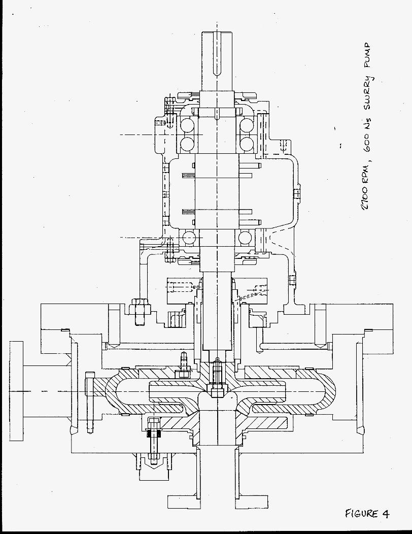
The previous optimum prototype slurry pump (2700 rpm, 600 Ns) designed during the earlier phases of this program was reconstructed. The same hydraulic design features were incorporated, but the material was mild steel (see Figure 4 ) . This soft steel will wear quicker on sand and water slurry, rapidly 'providing comparative wear data when run in series with the new prototype.
$
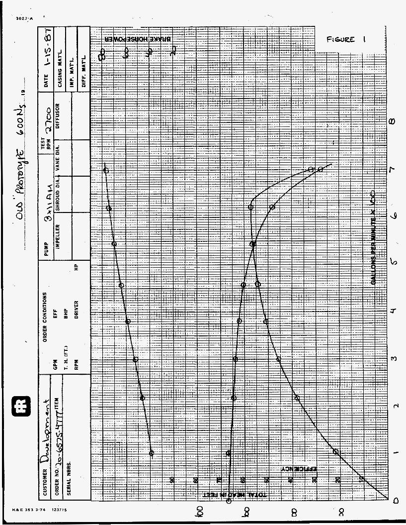
The pump was tested on clear water at 2700 rpm. It repeated the performance obtained earlier on the 28 percent chrome-iron verkion by producing 300 gpm at 320 ft. of total head with an efficiency of 46 percent (see Figure 1 ) .
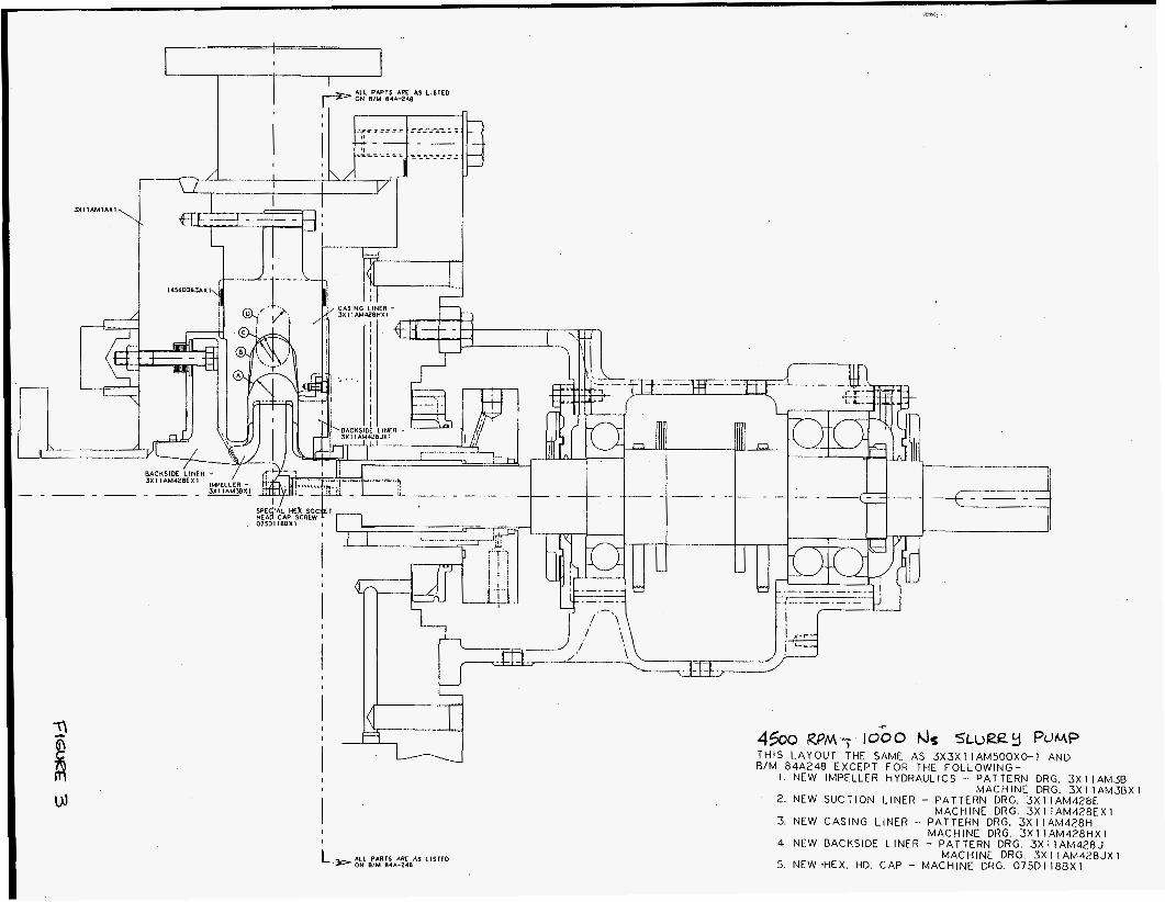
The new prototype slurry pump (4500 rpm, 1000 Ns) was designed and constructed. The advanced hydraulic design features were incorporated, and the material was again mild steel. (see Figure 3).
The gaps between the suction liner and front side of the impeller, and between the backside liner and back side of the impeller were 0.03 - 0.06" on the 600 Ns pump. The final gaps on the 1000 Ns pump were 0.13" at the front, and 0.06" at the back. The gaps should also have been 0.03 - 0.06". The importance of the tight gaps is to allow the radial "pumpout" vanes, that are cast onto the faces of the impeller, to pump out the slurry which would leak back into the suction stream at the impeller eye. This will reduce efficiency and cause greater wear at the suction due to speed-up in the swirl of the leaking fluid. The new 1000 Ns prototype also incorporates a reversed assembly, where the impeller is enclosed the main volute liner by the back side liner prior to joining both This type of assembly means the dimensional stackup is prone to more variations due to the machining that is done to all the other components. The final gaps are then determined after assembly, and cannot be changed if they are excessive, as happened in this case. As a new design the first run of parts did not satisfy the dimensional stackup per the original layout; and there was only one set of components available.
leakage
in halves of the pump case.
Future runs should not have this problem.
The pump was tested on clear water at 3600 rpm. It produced 300 gpm at 194 ft of total head with an efficiency of 66 percent. The data was extrapolated by applying the affinity. laws to 4270 and 4500 rpm. The design point of 300 gpm at 320 ft coincided with 4500 rpm (see Figure 2 ) . Both slurry pumps could then be operated at nearly identical conditions for making direct wear comparisons.
Continued....
The two pumps were set in series in the slurry test loop. The 4500 rpm, 1000 Ns pump preceded the 2700 rpm, 600 Ns pump. Both were operated for 24 hrs continuously with 30 percent wt. AFS HllO sand (-110 mesh) and water slurry at 80F. No problems were encountered during this period. The head and flow with water for each pump was as previously reported, 320 ft C! 300 gpm. The head was established for each pump via four pressure breakdown orifices. The slurry caused the head and flow to change to 305 ft @ 265 gpm (the slurry density was measured as 75 lblft”3). The head and flow on slurry remained 300 ft @ 260 gpm after 24 hours. A sand sample was taken, and found to show no loss of particle size or sharpness (visually 50x) after that time. The average bearing block and bearing case temperatures on the lower speed pump were 120 P, and were $65 F on the higher speed pump during operation.
Wear measurements (weights and dimensions) were recorded after the 24 hr run. The percentage weight loss for each component of both pumps was found to be as follows:
1000 Ns Pump 600 Ns Pump
Impeller = Suction Liner = Main, volute Liner = Backside Liner =
Total =
7.8% 2.0% 2.4% 5.1%
4.4% 3.4% 4.0% 8.1%
17.3% 19.9%
The visual differences in wear were primarily seen on the impellers and backside liners. The higher speed impeller displayed more localized wear, Included in this area were grooves that formed on the outer diameter inside each vane. This is attributed to the leakage of slurry into the suction stream across the eye since the front pumpout gap is excessive. The lower speed backside liner displayed more wear, primarily at the inside diameter. This is attributed to the normal assembly arrangement, which exposes the liner mounting bolt heads to the slurry. The higher flow velocity at the smaller diameter, and the turbulence of the activities in and around the bolt heads promotes the wear in this area. This deficiency could easily be corrected in a production design. Visually, the cutwater, impeller exit areas, and main volute A preliminary conclusion at this point is that the higher speed puplp may have exceeded the practical limit for blade speed in the area of the suction eye. Whereas the lower speed pump probably has a lower blade speed than might be possible.
primarily at the diameter of the suction eye.
liner faces are all wearing uniformly.
The pumps were reassembled and restarted on slurry to accumulate another 24 hours of endurance testing. At the 26 hour mark a shaft bearing failed
Continued....
in the higher speed pump. The pump was repaired. The testing will resume in the next quarter. However, it is anticipated that not more than another 22 hours will be required to expose the extreme differences of the wear rates already seen. Because of the soft steel being used for the components in this test, the wear will soon begin to effect pump performance. Prior to that, hydraulic performance data will be obtained to compare operation on slurry versus clear water.
GEB1087:emb t
1 '
-30 2 7:A
u) z P t 0 z 0 u
4
7 c
M
rJ
8 KfkE 353 3-74 123715 8

G;3027-A 7
b
0, c
0
v) z 0 c P z 0 V
ti n e 0
3
a w
a
I I
I ALL PAPTS APE AS LISTED ON WM WA-240
3x1 I A M I A X 1 .
4500 RPM-; IOGo us SLVRay POMP THIS LAYOUT THE SAME AS 3 X 3 X l l A M 5 0 0 X O - 1 AND B / M 84A248 EXCEPT FOR THE FOLLOWING-
I . NEW IMPELLER HYDRAULICS -- PATTERN DRG. 3X11AM3B
2. NEW SUCTION LINER - PATTERN DRG. 3 X l l A M 4 2 8 E
3. NEW CASING LINER - PATTERN DRG. 3x1 I A M 4 2 8 H MACHINE DRG. 3 X 1 lAM428HX 1
4. NEW BACKSIDE LINER - PATTERN DRG. 3 X l l A M 4 2 8 J
5. NEW .HEX. HD. CAP - MACHINE DRG. 0 7 5 0 1 1 8 B X l
MACHINE DRG. 3x1 l A M 3 B X l
MACHINE DRG. 3 x 1 1AM428EX l
MACHINE DRG 3 X I IAM428JX I
I
I I I I I I
d" d 3 J
0 0 4
4 a Li 0 Q 6

' *
0 INCERSOLLRAND Pump Group .
Ingersoll-Rand Company 942 M e m o r i a l Parkway Phillipsburg, NJ 08865
~, , -: - ' i t
* -J3eseaich 6.DeydrJpmertt - L' " I . - - \
October 12, 1987
Mr. Swenam R. Lee U. S. Department of Energy Pittsburgh Energy Technology Center P. 0. Box 10940 Pittsburgh, PA 15236
Subject: Quarterly Technical Progress Report 1 April 1987 - 30 June 1987
Dear Mr. Lee:
Enclosed are three (3) copies of the Quarterly Technical Progress Report for the period of April 1, 1987 - June 30, 1987 for Contract DE-AC22-82PC50035.
Sincerely yours,
INGERGOU-RAND COMPANY
Paul Cooper, DiGector Research & Development Pump Group
Dept .
.Robert J: Mondschein, Supervisor Government Contracts
Enc . CC: -Contract Specialist, DOE Pittsburgh - 2 Copies
T. Simpson, DOE, Washington - 1 Copy
PC22887:elb
Au AGREEMENTS CONTINGENT UPON STRIKES. ACCIDENTS AND OTHER CONDITIONS BEYOND OUR CONTROL ALL CONTRACTS ARE SUBJECT TO APPROVAL BY AN OFFICER OF THE COMPANY WOTATIONS SUBJECT TO CHANGE WITHOUT NOTICE
CENTRIFUGAL SLURRY PUMP
WEAR & HYI)RAULIC STUDIES
Quarterly Technical Progress Report
For The Period Of
1 April 1987 - 30 June 1987
Paul Cooper
INGERSOLL-RAND COMPANY 942 Memorial Parkway
Phillipsburg, NJ 08865
Prepared For The
U. S. Department of Energy
Pittsburgh Energy Technology Center
Under Contract
DE-AC22-82PC50035
DISCLAIMER NOTICE
The following report was prepared as an account of work sponsored by the United States Government. Neither the employees, nor any contractors, subcontractors, or their employees make any warrant, expressed or implied, or assume any legal liability or responsibility for the accuracy, completeness, or usefulness of any information, apparatus, product, or process disclosed, or represent that its use would not infringe privately owned rights.
- . . . _ _ ..,.-. _.
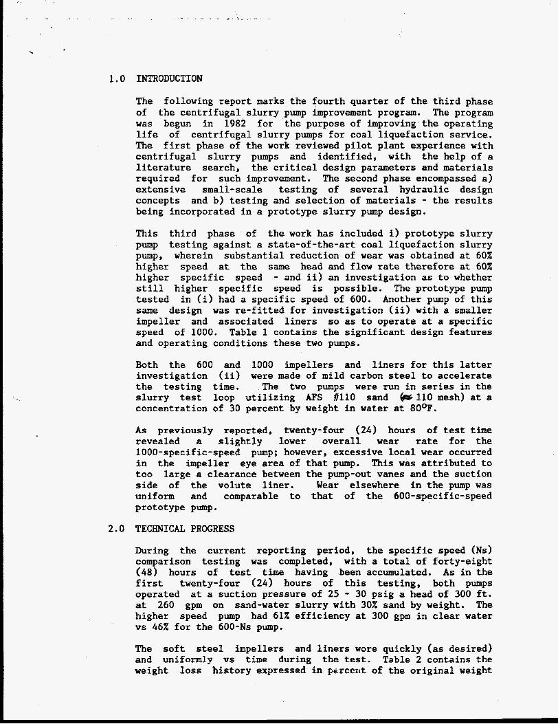
1.0 INTRODUCTION
The following report marks the fourth quarter of the third phase of the centrifugal slurry pump improvement program. The program was begun in 1982 for the purpose of improving the operating life of centrifugal slurry pumps for coal liquefaction service. The first phase of the work reviewed pilot plant experience with centrifugal slurry pumps and identified, with the help of a literature search, the critical design parameters and materials required for such improvement. The second phase encompassed a) extensive small-scale testing of several hydraulic design concepts and b) testing and selection of materials - the results being incorporated in a prototype slurry pump design.
This third phase of the work has included i) prototype slurry pump testing against a state-of-the-art coal liquefaction slurry pump, wherein substantial reduction of wear was obtained at 60X higher speed at the same head and flow rate therefore at 60% higher specific speed - and ii) an investigation as to whether still higher specific speed is possible. The prototype pump tested Another pump of this same design was re-fitted for investigation (ii) with a smaller impeller and associated liners so as to operate at a specific speed of 1000. Table 1 contains the significant design features and operating conditions these two pumps.
in (i) had a specific speed of 600.
Both the 600 and 1000 impellers and liners for this latter investigation (ii) were made of mild carbon steel to accelerate the testing time. The two pumps were run in series in the slurry test loop utilizing AFS tll0 sand &I10 mesh) at a concentration of 30 percent by weight in water at 80°F.
As previously reported, twenty-four (24) hours of test time revealed a slightly lower overall wear rate for the 1000-specific-speed pump; however, excessive local wear occurred in the impeller eye area of that pump. This was attributed to too large a clearance between the pump-out vanes and the suction side of the volute liner. Wear elsewhere in the pump was uniform and comparable to that of the 600-specific-speed prototype pump.
2.0 TECHNICAL PROGRESS
During the current reporting period, the specific speed (Ns) comparison testing was completed, with a total of forty-eight (48) hours of test time having been accumulated. As in the first twenty-four (24) hours of this testing, both pumps operated at a suction pressure of 25 - 30 psig a head of 300 ft. at 260 gpm on sand-water slurry with 30% sand by weight. The higher speed pump had 612 efficiency at 300 gpm in clear water vs 46% for the 600-Ns pump.
The soft steel impellers and liners wore quickly (as desired) and uniformly vs time during the test. Table 2 contains the weight loss history expressed in percent of the original weight
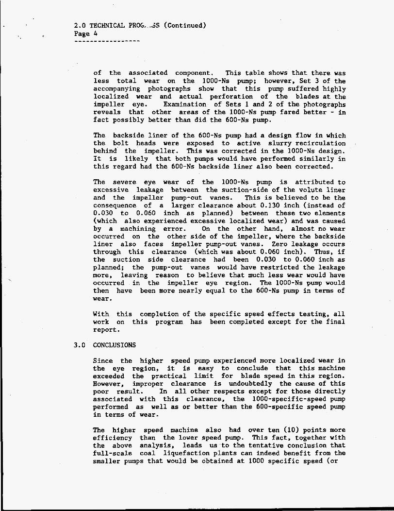
c
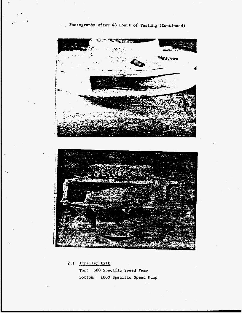
of the associated component. This table shows that there was less total wear on the 1000-Ns pump; however, Set 3 of the accompanying photographs show that this pump suffered highly localized wear and actual perforation of the blades at the impeller eye. Examination of Sets 1 and 2 of the photographs reveals that other areas of the 1000-Ns pump fared better - in fact possibly better than did the 600-Ns pump.
The backside liner of the 600-Ns pump had a design flow in which the bolt heads were exposed to active slurry recirculation behind the impeller. This was corrected in the 1000-Ns design. It is likely that both pumps would have performed similarly in this regard had the 600-Ns backside liner also been corrected.
The severe eye wear of the 1000-Ns pump is attributed to excessive leakage between the suction-side of the volute liner and the impeller pump-out vanes. This is believed to be the consequence of a larger clearance about 0.130 inch (instead of 0.030 to 0.060 inch as planned) between these two elements (which also experienced excessive localized wear) and was caused by a machining error. On the other hand, almost no wear occurred on the other side of the impeller, where the backside liner also faces impeller pump-out vanes. Zero leakage occurs through this clearance (which was about 0.060 inch). Thus, if the suction side clearance had been 0.030 to 0.060 inch as planned; the pump-out vanes would have restricted the leakage more, leaving reason to believe that much less wear would have occurred in the impeller eye region. The 1000-Ns pump would then have been more nearly equal to the 600-Ns pump in terms of wear.
With this completion of the specific speed effects testing, all work on this program has been completed except for the final report.
3.0 CONCLUSIONS
Since the higher speed pump experienced more localized wear in the eye region, it is easy to conclude that this machine exceeded the practical limit for blade speed in this region. However, improper clearance is undoubtedly the cause of this poor result. In all other respects except for those directly associated with this clearance, the 1000-specific-speed pump performed well as or better than the 600-specific speed pump in terms of wear.
as
The higher speed machine also had over ten (10) points more efficiency than the lower speed pump. This fact, together with the above analysis, leads us to the tentative conclusion that full-scale coal liquefaction plants can indeed benefit from the smaller pumps that would be obtained at 1000 specific speed (or

3.0 CONCLUSIONS (Continued) Page 5
' r
-------c-------
more) than would result if the lower specific speeds of this study and of the pilot plants (still lower) were used. These benefits are higher efficiency and wear rates that do not exceed those of lower specific speed pumps containing the same hydraulic improvements that were proven in the earlier testing of this program.
TABLE 1
Design Features and Operating Conditions of Slurry Pumps Used in Specific Speed Investigation
Specific Speed
OriRinal Prototype
600
Design Flow Rate, GPM 300
Head, Ft. (in water at above flow rate) 320
Flow Rate When Operating On Slurry (30% sand; Density = 75 lbm/ft3,GPM 260
Head at Slurry Flow Rate, ft. 300
Speed, RPM 2700
Impeller Diameter, in. 11.25
Ratio of Cutwater Diameter To Impeller Diameter 1.46
Impeller Exit Tip Speed, ft/sec
Impeller Inlet Absolute Velocity, f t /sec
133
36
New Prototype
1000
300
320
260
300
4500
7.00
1.34
137
47

TABLE 2 Page 6 -------
TABLE 2
Centrifugal Slurry Pump Component
of two pumps of different specific speed, Ns. Weight Loss vs Time. Comparison is made
Component
1. 24 Hours
Impeller
Suction Liner
Main (Volute) Liner
Backside Liner
Total --------------
2. 48 Hours
Impeller
Suction Liner
Main (Volute) Liner
Backside Liner
Total (Cumulative) --------------
PC22887:elb
Cumulative Weight Loss, X
600-NS Pump 1000-Ns Pump
4.4 7.8
3.4 2.0
4.0 2.4
8.1
P9.9 ---
7.8
4.0
8.3
5.1
17.3 ---
17.6
2.4
3.8
9.2
33.0 ---

Photographs of Carbon Steel Pump Intemals After 48 Hours of Testing in 30% Sand-Water Slarry. (Flow Rate Was 260 GPM and Head Was 300 f t . per lku~p . )
- 4 . -
A -
1.) Volute and Cutwater
Above: 600 S p e c i f i c Speed PUmp
Left: 1000 S p e c i f i c Speed pump
Photographs After 48 Hours of Testing (Continued)
2.) Impeller Exit Top: 600 Specific Speed Pump
Bottom: 1000 Specific Speed Pump

3.) Impe l l er Eye
Top: 600 S p e c i f i c Speed Pump
Bottom: 1000 S p e c i f i c Speed Pump

INGERSOLL-RAND
October 26, 1987
M r . Swenam R. L e e U. S. Department of Energy P i t t s b u r g h Energy Technology Center P. 0. Box 10940 P i t t s b u r g h , PA 15236
Subjec t : Q u a r t e r l y Technica l Progress Report 1 July 1987 - 30 September 1987
Dear M r . Lee:
Enclosed are t h r e e (3) copies of the Q u a r t e r l y Technical Progress Report f o r t h e pe r iod of J u l y 1, 1987 - September 30, 1987 f o r Cont rac t DE-AC22-82PC50035.
S i n c e r e l y yours,
INGERGOU-RAND COMPANY
Paul Cooper, D i i e c t o r Research & Development Dept. Pump Group
'Robert J. dondsdhein, Superv isor Government Cont rac ts
Enc . CC: Cont rac t S p e c i a l i s t , DOE P i t t s b u r g h - 2 Copies
T. Simpson, DOE, Washington - 1 Copy
PC22887:elb
ALL AGREEMENTS CONTINGENT UPON STRIKES. ACCIDENTS AND OTHER CONDITIONS BEYOND OUR CONTROL. ALL CONTRACTS ARE SUBJECT TO APPROVAL BY AN OFFICER OF THE COMPANY QUOTATIONS SUfUECT TO CHANGE WITHOUT NOTICE

CENTRIFUGAL SLURRY PUMP
WEAR & HYDRAULIC STUDIES
Quarterly Technical Progress Report
For The Period Of
1 July 1987 - 30 September 1987
Paul Cooper
INGERSOLL-RAND COMPANY 942 Memorial Parkway
Phillipsburg, NJ 08865
Prepared For The
U. S. Department of Energy
Pittsburgh Energy Technology Center
Under Contract
DE-AC22-82PC50035

DISCLAIMER NOTICE t
The following report was prepared as an account of work sponsored by the United States Government. Neither the employees, nor any contractors, subcontractors, or their employees make any warrant, expressed or implied, or assume any legal liability or responsibility for the accuracy, completeness, or usefulness of any information, apparatus, product, or process disclosed, or represent that its use would not infringe privately owned rights.
J.

1.0 INTRODUCTION
The following report marks the fifth and final quarter of the third phase of the centrifugal slurry pump improvement program. The program was begun in 1982 f o r the purpose of improving the operating life of centrifugal slurry pumps for coal liquefaction
experience with centrifugal slurry pumps and identified, with the help of a literature search, the critical design parameters and materials required for such improvement. The second phase encompassed a) extensive small-scale testing of geveral hydraulic design concepts and b) testing and selection of materials - the results being incorporated in a prototype slurry pump design.
P service. The first phase of the work reviewed pilot plant
This third phase of the work included i) prototype slurry pump testing against a state-of-the-art coal liquefaction slurry pump, wherein substantial reduction of wear was obtained at 60% higher speed at the same head and flow rate therefore at 60% higher specific speed - and ii) an investigation as to whether still higher specific speed is possible. The prototype pump tested Another pump of this same design was re-fitted for investigation (ii) with a smaller impeller and associated liners so as to operate at a specific speed of 1000. Table 1 contains the significant design features and operating conditions these two pumps.
in (i) had a specific speed of 600.
2.0
Both the 600 and 1000 impellers and liners for this latter investigation (ii) were made of mild carbon steel to accelerate the testing time. The two pumps were run in series in the slurry test loop utilizing sand at a concentration of 30 percent by weight in water at 80°F.
As previously reported, the specific speed comparison was completed in forty-eight ( 4 8 ) hours of test time. This revealed a slightly lower overall wear rate for the 1000-specific-speed pump; however, excessive local wear occurred in the impeller eye area of that pump. This was attributed to too large a clearance between the pump-out vanes and the suction side of the volute liner. Wear elsewhere in the pump was uniform and comparable to that of the 600-specific-speed prototype pump.
TECHNICAL PROGRESS
Since the previous quarterly reporting period, during which all testing was completed, analysis of the data has been completed.
This analysis reinforces the assumption that the excessive damage to the 1000-Ns pump in the impeller blade inlet region was due to uncontrolled leakage past the front conical neck ring seal of the impeller. Clearance in front of the impeller front pump-out vaner w a s 0.130 inch, the vanes being 0.190 inch wide. This to highly swirling fluid in the amount of about 15% of the net flow rate of 260 gpm impinging on the suction sides of the impeller blades. This return-leakage fluid was all flowing
led
in an annular zone adjacent to the impeller front shroud. The main body of incoming fluid was not swirling; so, when these two ( 2 ) flows interacted, longitudinal vortices were set up that trapped solid particles. These vortices thus caused the observed gouging and loss of blade material along the suction sides of the blades near the shroud.
Thus, if the leakage had been properly inhibited by a smaller clearance in front of the pump-out vanes on the inlet side of the impeller, this wear would not have occurred, and the higher specific speed pump would have as long a predicted l i f e as the 600-N, machine.
c
The first draft of final report, detailing the entire program was 50% completed in handwritten form.
3.0 CONCLUSIONS
The above analysis leads us to the conclusion that full-scale coal liquefaction plants can indeed benefit from the smaller pumps that would be obtained at 1000 specific speed (or more) than would result if the lower specific speeds of this study and of These benefits are higher efficiency and wear rates that do not exceed those of lower specific speed pumps containing the same hydraulic improvements that were proven in the earlier testing of this program.
the pilot plants (still lower) were used.
TABLE 1
Design Features, Operating Conditions and Results For Slurry Pumps Used In Specific Speed Investigation
c
Specific Speed
Design Flow Rate, GPM
Head, Ft. (in water at above flow rate)
Flow Rate When Operating On Slurry (30% sand; Density = 75 lbm/ft3),gpm
Head at Slurry Flow Rate, ft.
Speed, RPM
Impeller Diameter, in.
Ratio of Cutwater Diameter To Impeller Diameter
Impeller Exit Tip Speed, ftlsec
Impeller Inlet Tip Speed, ft/sec
Prototype I
600
300
320
300
2700
11.25
1.46
133
38
!Prototype I1
1000
300
320
260
300
4500
7.00
1.34
137
49
Cumulative Weight Loss, %
a) Impeller b) Suction Liner c) Main (Volute) Liner d) Backside Liner
Total (After 48 Hours of Testing)
7.8 4 . 0 8 . 3 16.3 ---- 36.4
17.6 2.4 3.8 9.2 ---- 33.0

TABLE 2 Page 6
TABLE 2
?
Centrifugal Slurry Pump Component
of two pumps of different specific speed, Ns, .Weight Loss vs Time. Comparison is made
1
Component
1. 24 Hours
Impeller
Suction Liner
Main (Volute) Liner
Backside Liner
Total --------------
2. 48 Hours
Impeller
Suction Liner
Main (Volute) Liner
Backside Liner
Total (Cumulative) _-------------
Cumulative Weight Loss, %
600-NS Pump 1000-Ns Pump
4.4
3 . 4
4.0
8.1
19.9 ---
7.8
4.0
8.3
16.3
36.4 ----
7.8
2.0
2.4
5.1
17.3 ---
17.6
2.4
3.8
9.2
33.0 ---
PC22887:elb