CENTRIFUGAL PUMP - inoxpa.com de instruccions/Components/Bombes...HYGINOX SE is a range of...
24
INSTALLATION, SERVICE AND MAINTENANCE INSTRUCTIONS CENTRIFUGAL PUMP HYGINOX SE Original instructions 01.011.30.07EN (0) 2019/09 01.011.32.0015
Transcript of CENTRIFUGAL PUMP - inoxpa.com de instruccions/Components/Bombes...HYGINOX SE is a range of...

INSTALLATION, SERVICE AND MAINTENANCE INSTRUCTIONS
CENTRIFUGAL PUMP
HYGINOX SE
Original instructions
01.011.30.07EN
(0) 2019/09
01
.01
1.3
2.0
01
5

01.011.30.080EN
(0) 2019/09
(1) The serial number may be preceded by a slash and by one or two alphanumeric characters
01.011.30.08EN (0) 2019/09
EC Declaration of Conformity
We,
INOXPA, S.A.U.
Telers, 60
17820 – Banyoles (Girona)
Hereby declare under our sole responsibility that the machine
CENTRIFUGAL PUMP
Designation
HYGINOX SE
Type
HYGINOX SE-15, HYGINOX SE-20, HYGINOX SE-26, HYGINOX SE-28, HYGINOX SE-35, HYGINOX SE-36
From serial number IXXXXXX to IXXXXXX (1) / XXXXXXXXXIIN to XXXXXXXXXIIN (1)
Fulfills all the relevant provisions of the following directive:
Machinery Directive 2006/42/CE
Applicable harmonized standards:
EN ISO 12100:2010
EN 809:1998+A1:2009/AC:2010
EN 60204-1:2006+A1:2009
The technical file has been prepared by the signer of this document in INOXPA.
Signed by and on behalf of INOXPA S.A.U.
David Reyero Brunet
Technical Office Manager
Banyoles, September 30, 2019
INOXPA S.A.U. · 01.011.30.07EN · (0) 2019/09 3
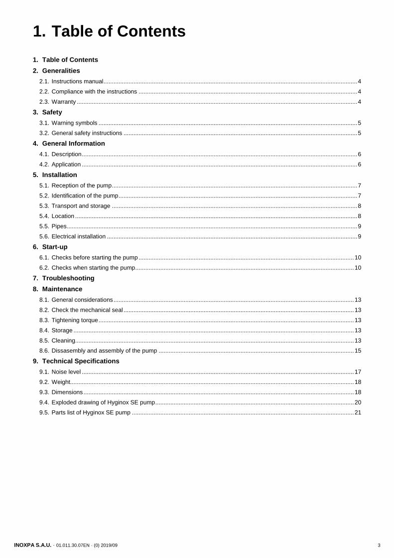
1. Table of Contents
1. Table of Contents
2. Generalities
2.1. Instructions manual ........................................................................................................................................................ 4
2.2. Compliance with the instructions ................................................................................................................................... 4
2.3. Warranty ........................................................................................................................................................................ 4
3. Safety
3.1. Warning symbols ........................................................................................................................................................... 5
3.2. General safety instructions ............................................................................................................................................ 5
4. General Information
4.1. Description ..................................................................................................................................................................... 6
4.2. Application ..................................................................................................................................................................... 6
5. Installation
5.1. Reception of the pump ................................................................................................................................................... 7
5.2. Identification of the pump ............................................................................................................................................... 7
5.3. Transport and storage ................................................................................................................................................... 8
5.4. Location ......................................................................................................................................................................... 8
5.5. Pipes .............................................................................................................................................................................. 9
5.6. Electrical installation ...................................................................................................................................................... 9
6. Start-up
6.1. Checks before starting the pump ................................................................................................................................. 10
6.2. Checks when starting the pump ................................................................................................................................... 10
7. Troubleshooting
8. Maintenance
8.1. General considerations ................................................................................................................................................ 13
8.2. Check the mechanical seal .......................................................................................................................................... 13
8.3. Tightening torque ......................................................................................................................................................... 13
8.4. Storage ........................................................................................................................................................................ 13
8.5. Cleaning....................................................................................................................................................................... 13
8.6. Dissasembly and assembly of the pump ..................................................................................................................... 15
9. Technical Specifications
9.1. Noise level ................................................................................................................................................................... 17
9.2. Weight.......................................................................................................................................................................... 18
9.3. Dimensions .................................................................................................................................................................. 18
9.4. Exploded drawing of Hyginox SE pump ....................................................................................................................... 20
9.5. Parts list of Hyginox SE pump ..................................................................................................................................... 21
Generalities
4 INOXPA S.A.U. · 01.011.30.07EN · (0) 2019/09
2. Generalities
2.1. INSTRUCTIONS MANUAL
This manual contains information regarding the reception, installation, operation, assembly, disassembly and maintenance of the HYGINOX SE pump.
Carefully read the instruction prior to starting the pump, familiarize yourself with the installation, operation and correct use of the filter and strictly follow the instructions. These instructions should be kept in a safe location near the installation area.
The information published in the instruction manual is based on updated data.
INOXPA reserves the right to modify this instruction manual without prior notice.
2.2. COMPLIANCE WITH THE INSTRUCTIONS
Not following the instructions may impose a risk for the operators, the environment and the machine, and may result in the loss of the right to claim damages.
This non-compliance may result in the following risks:
• failure of important machine/plant functions,
• failure of specific maintenance and repair procedures,
• possible electrical, mechanical and chemical hazards,
• risk to the environment due to the type of substances released.
2.3. WARRANTY
Any warranty will be void immediately and lawfully and, additionally, INOXPA will be compensated for any civil liability claims submitted by third parties, in the following cases:
• the service and maintenance work have not been carried out in accordance with the service instructions, the repairs have not been carried out by our personnel or have been carried out without our written authorisation,
• modifications have been carried out on our material or equipment without written authorisation,
• the parts or lubricants used are not original INOXPA parts and products,
• the material or equipment has been improperly used, has been used negligently, or has not been used according to the instructions and their intended,
• the pump parts are damaged because they have been subjected to high pressure due to not having used a safety valve.
The General Conditions of Delivery already in your possession are also applicable.
The machine may not undergo any modification without prior approval from the manufacturer.
For your safety, only use original spare parts and accessories.
The usage of other parts will relieve the manufacturer of any liability.
Changing the service conditions can only be carried out with prior written authorization from INOXPA.
Please do not hesitate to contact us in case of doubts or if further explanations are required regarding specific data (adjustments, assembly, disassembly, etc.)

Safety
INOXPA S.A.U. · 01.011.30.07EN · (0) 2019/09 5
3. Safety
3.1. WARNING SYMBOLS
Safety hazard for people in general and/or for equipment
Electric hazard
Important instruction for the protection of the equipment and its functions
3.2. GENERAL SAFETY INSTRUCTIONS
Read the instruction manual carefully before installing and starting the pump. Contact INOXPA in case of doubt.
3.2.1. During the installation
The Technical Specifications of chapter 9 should always be observed.
Never start the pump before connecting it to the lines.
Do not operate the pump if the pump cover is not fitted.
Check for proper specifications of the motors, especially it its working conditions create an explosions hazard.
During the installations, all the electric work should be carried out by authorized personnel.
3.2.2. During operation
The Technical Specifications of chapter 9 should always be observed. Under no circumstances can the specified limit values be exceeded.
NEVER touch the pump or the pipework during operation if the pump is being used for transferring hot liquids or during cleaning.
The pump contains moving parts. Never place your fingers inside the pump during operation.
NEVER operate with the suction and discharge valves closed.
NEVER spray water directly on the electrical motor. The standard motor protection is IP55: protection against dust and water spray.
3.2.3. During maintenance
The Technical Specifications of chapter 9 shall always be observed.
NEVER disassemble the pump until the pipes have been emptied. Remember that liquid will remain inside the pump’s pump casing (if does not have a purge). Bear in mind that the pumped liquid may be hazardous or extremely hot. Consult the regulations in effect in each country for these cases.
Do not leave loose parts on the floor.
ALWAYS disconnect the electrical power to the pumps prior to carrying out any maintenance.
Remove the fuses and disconnect the cable from the motor’s terminals.
All electrical work must be carried out by authorized personnel
ATTENTION

General Information
6 INOXPA S.A.U. · 01.011.30.07EN · (0) 2019/09
4. General Information
4.1. DESCRIPTION
HYGINOX SE is a range of close-coupled centrifugal pump with hygienic design. This single-stage horizontal pump has a circular casing with axial suction and tangential discharge. The main pump components are pump casing, impeller, cover, lantern and a shaft which is rigidly coupled to the motor shaft.
The standard IEC motor of type IM B34 is protected by a stainless steel shroud and provided with a height adjustable stainless steel legs.
4.2. APPLICATION
As a general rule, HYGINOX SE pumps in their standard versions are used in the food industry mainly to transfer liquids.
For each type of the pump, the hydraulic performance is given by the choice of impeller diameters and speeds. The characteristic curves also show the power and NPSH requirements. The intended use of the pump is defined by its characteristic curve and operating limits provided in the 9. Technical Specifications.
The range of application for each type of pump is limited. The pump was selected for a given set of pumping conditions when the order was placed. INOXPA shall not be liable for any damage resulting from the incompleteness of the information provided by the purchaser (nature of the fluid, RPM, etc.).
ATTENTION

Installation
INOXPA S.A.U. · 01.011.30.07EN · (0) 2019/09 7
5. Installation
5.1. RECEPTION OF THE PUMP
INOXPA cannot be held responsible for the damage sustained by the equipment during transport or unpacking. Please visually check that the packaging is not damaged.
The pump package includes the following documents:
• shipping documents,
• installation, service and maintenance instructions manual,
• instructions and service manual of the motor1.
Unpack the pump and check the following:
• The suction and discharge connections of the pump, removing any rest of packaging materials,
• The pump and the motor are not damaged,
• If the equipment is not in good condition and/or any part is missing, the carrier should report accordingly as soon as possible.
5.2. IDENTIFICATION OF THE PUMP
Each pump has a nameplate with the basic data required to identify the model.
1 If the pump has been supplied with a motor from INOXPA
Serial number
01
.01
1.3
2.0
00
2
01
.01
1.3
2.0
01
6

Installation
8 INOXPA S.A.U. · 01.011.30.07EN · (0) 2019/09
5.3. TRANSPORT AND STORAGE
The HYGINOX SE pumps are often too heavy to be stored manually.
Use an appropriate means of transport.
Use the points which are indicated in the drawing for lifting the pump.
Only authorized personnel should transport the pump.
Do not work or walk under the heavy loads.
Lift the pump as indicated below:
• Always use two support points placed as far apart as possible.
Always remove the motor shroud before hoisting
• Secure the supports so that they will not move.
See chapter 9. Technical Specifications to consult dimensions and weights.
During the transport, disassembly or assembly of the pump, there is a risk of loss of stability and that the pump could fall down and cause damages to the operators. Make sure that the pump is properly supported.
5.4. LOCATION
Place the pump in position that allows enough space around it to provide access to the pump as well as to the motor. See chapter 9. Technical Specifications to consult dimensions and weights.
Install the pump so as to allow proper ventilation.
If the pump is installed outdoors, it should be covered by a roof. Its location should allow easy access for inspection or maintenance operations.
5.4.1. Excessive temperatures
Depending on the fluid to be pumped, high temperatures can be reached inside and around the pump.
ATTENTION
ATTENTION
ATTENTION
01
.01
1.3
2.0
00
3
ATTENTION

Installation
INOXPA S.A.U. · 01.011.30.07EN · (0) 2019/09 9
Over 68ºC the operator should take protective measures and place warning notices advising of the danger which exists if the pump is touched.
The type of protection selected should not isolate the pump entirely. It should allow for the bearings to be cooled more efficiently and for the bearings to be lubricated.
5.5. PIPES
• As a general rule, install the suction and discharge lines in straight sections, with the minimum possible number of elbows and fittings in order to reduce any pressure losses that may be caused by friction.
• Make sure that the pump’s ports are properly aligned with the pipework and have a diameter similar to that of the pump connections.
• Place the pump as close as possible to the suction tank and whenever possible below the liquid level, or even below the tank level in order to achieve the largest possible static head for suction.
• Install support brackets for the lines as close as possible to the pump’s suction and discharge ports in order to avoid vibrations and stress on the pump.
5.5.1. Shut-off valves
The pump may be isolated for maintenance. To accomplish this, shut-off valves must be installed and connected to the pump’s suction and discharge connections.
These valves must ALWAYS be open during operation of the pump.
5.6. ELECTRICAL INSTALLATION
Only qualified personnel can connect the electric motors.
Take the necessary measures to prevent damage to cables and connections.
Electrical equipment, terminals and components of the control systems may still carry current when they are disconnected. Contacting them may impose a hazard to operators or cause irreparable material damage.
Before handling the pump, make sure that the motor is stopped.
Connect the motor in accordance with the instructions supplied by the motor manufacturer, in accordance with the current national legislation and in compliance with EN 60204-1.
Check the direction of rotation (see the signalling label on the pump).
Start and stop the pump motor momentarily. Make sure that the direction of rotation is correct. If the pump rotates in the wrong direction it could cause serious damage.
See indicator label on the pump.
ALWAYS check the direction of rotation of the motor with liquid inside the pump.
ATTENTION
ATTENTION 01
.01
1.3
2.0
00
4
See from the rear of the motor

Start-up
10 INOXPA S.A.U. · 01.011.30.07EN · (0) 2019/09
6. Start-up
Prior to starting the pump, carefully read the instructions in chapter 5. Installation.
Carefully read section 9. Technical Specifications. INOXPA will not be liable for improper use of the equipment.
NEVER touch the pump or the lines if hot liquids are being pumped.
6.1. CHECKS BEFORE STARTING THE PUMP
Completely open the shut-off valves on the suction and discharge lines.
If liquid does not flow towards the pump, fill it with the liquid to be pumped.
The pump must never turn dry.
Check that the power supply matches the rating indicated on the motor plate.
Check that the direction of rotation of motor is the right one.
6.2. CHECKS WHEN STARTING THE PUMP
• Check that the pump is not making any strange noises.
• Check if the absolute inlet pressure is sufficient to prevent cavitation in the pump. See the curve to determine the minimum pressure required above steam pressure (NPSHr).
• Control the discharge pressure.
• Check for leaks in the sealing areas.
Shut-off valves on the suction pipe must not be used to regulate the flow. All shut-off valves must be fully open during operation.
Control the motor consumption to prevent an electrical overload.
Reduce the flow rate and the electrical power consumed by the motor:
by regulating the pump’s discharge flow
by decreasing the motor speed
ATTENTION
ATTENTION
ATTENTION
01
.01
1.3
2.0
00
5
Start-up
INOXPA S.A.U. · 01.011.30.07EN · (0) 2019/09 11
Use special protection when the sound pressure in the operation area exceeds 85 dB(A).

Troubleshooting
12 INOXPA S.A.U. · 01.011.30.07EN · (0) 2019/09
7. Troubleshooting
The following table provides solutions to problems that might arise during the operation of the pump. The pump is assumed to have been properly installed and be suitable for the relevant application.
Please contact INOXPA if technical assistance is required.
Motor overload
The pump does not provide enough flow or pressure
No pressure on the discharge side
Uneven discharge flow / pressure
Noise and vibration
The pump gets clogged
Overheated pump
Excessive wear
The mechanical seal leaks
PROBABLE CAUSES SOLUTIONS
• • Wrong direction of rotation Reverse the direction of rotation
• • • • NPSH is not high enough
Raise the suction tank Lower the pump Reduce the vapour pressure Widen the diameter of the suction pipe Shorten and simplify the suction line
• Pump not drained Drain or fill
• • • • Cavitation Increase suction pressure
• • • • Air is suctioned by the pump Check the suction pipe and all its connections
• • • Clogged suction pipe Check the suction pipe and all its filters, if any
• • Discharge pressure too high If necessary, reduce load losses, e.g. by increasing the pipe diameter
• • • Flow too high
Reduce the flow by means of a diaphragm. Partially close the discharge valve. Trim the impeller Decrease speed
• • • • • • Fluid viscosity too high Reduce the viscosity, e.g. by heating the fluid
• • • • • Fluid temperature too high Reduce the temperature by cooling the fluid
• Mechanical seal damaged or worn out
Replace the seal
• O-rings unsuitable for the fluid Fit suitable O-rings. Consult the manufacturer.
• • • • The impeller scrapes Lower the temperature Reduce the suction pressure Adjust the impeller / cover play
• • • • Tension in the lines Connect the pipes to the pump without tension
• • • • Foreign matter in the liquid Install a filter in the suction pipe
• Mechanical seal spring tension Is too low
Adjust as indicated in this manual

Maintenance
INOXPA S.A.U. · 01.011.30.07EN · (0) 2019/09 13
8. Maintenance
8.1. GENERAL CONSIDERATIONS
This pump, just like any other machine, requires maintenance. The instructions contained in this manual cover the identification and replacement of spare parts. The instructions are aimed at maintenance personnel and those responsible for the supply of spare parts.
Carefully read chapter 9. Technical Specifications.
Maintenance work can only be carried out by qualified personnel that are trained and equipped with the necessary resources to carrying out this work.
All parts or materials that are replaced must be properly disposed of/recycled in accordance with the current directives applicable in each area.
ALWAYS disconnect the pump before beginning any maintenance work.
8.2. CHECK THE MECHANICAL SEAL
Periodically check that there are no leaks around the shaft. If leakage is detected through the mechanical seal, replace it following the instructions in the chapter 8.7. Disassembly and assembly of the pump.
8.3. TIGHTENING TORQUE
If not stated otherwise, the torques listed in the following table should be applied on the nuts and bolts of this pump.
Size Nm lbf·ft
M6 10 7
M8 21 16
M10 42 31
M12 74 55
M16 112 83
8.4. STORAGE
Before being stored the pump must be completely emptied of liquids. Avoid, as far as possible, the exposure of the parts to excessively damp atmospheres.
8.5. CLEANING
The use of aggressive cleaning products such as caustic soda and nitric acid may give raise to skin burns.
Use rubber gloves during cleaning procedures.
Always use protective goggles.
Maintenance
14 INOXPA S.A.U. · 01.011.30.07EN · (0) 2019/09
8.5.1. Automatic CIP (clean-in-place)
If the pump is installed in a system with a CIP process, it is not necessary to disassemble the pump.
If the automatic cleaning process is not provided, proceed to disassemble the pump as indicated in the chapter 8.7. Disassembly and assembly of the pump.
Check the concentration of the cleaning solutions. Incorrect concentrations may lead to the deterioration of the pump seals.
To remove any traces of cleaning products ALWAYS perform a final rinse with clean water at the end of the cleaning process.
8.5.2. Automatic SIP (sterilization-in-place)
The process of sterilization with steam is applied to all the equipment including the pump.
Do NOT start the pump during the process of sterilization with steam.
The parts/materials suffer no damage if the indications specified in this manual are observed.
No cold liquid can enter the pump till the temperature of the pump is lower than 60°C (140°F).
The pump generates an important pressure drop through de sterilization process, use a by-pass circuit provide with a discharge valve is recommended for ensuring that the steam or overheated water sterilize the circuit integrity.
Maximum conditions during SIP process with steam or overheated water:
a) Maximum temperature: 140°C / 284°F b) Maximum time: 30 min c) Cooling: sterile air or inert gas d) Materials: EPDM/PTFE (recommended)
FPM/NBR (not recommended)
ATTENTION
Cleaning solutions for CIP processes
Only use clear water (chlorine-free) to mix with the cleaning agents:
a. Alkaline solution: 1 % by weight of caustic soda (NaOH) a 70ºC (150ºF) 1 kg NaOH + 100 l H2O = cleaning solution
or
2,2 l NaOH of 33% + 100 l H2O = cleaning solution
b. Acid solution: 0,5% by weight of nitric acid (HNO3) a 70ºC (150ºF)
0,7 l HNO3 of 53% + 100 l H2O = cleaning solution

Maintenance
INOXPA S.A.U. · 01.011.30.07EN · (0) 2019/09 15
8.6. DISSASEMBLY AND ASSEMBLY OF THE PUMP
The assembly and disassembly of the pumps should be done by qualified personnel. Make sure that the personnel read carefully this instruction manual and, in particular, those instructions which refer to the work they will perform.
Incorrect assembly or disassembly may cause damage in the pump’s operation and lead to high repair costs and a long period of down time.
INOXPA is not responsible for accidents or damages cause by a failure to comply with the instructions in this manual.
Preparation
Provide for a clean working environment so some parts, including the mechanical seal, require very careful handling and others have close tolerances.
Check that the parts which are used are not damaged during transport. When doing this, you need to inspect the adjustment edge, the butted faces, the tight fit, burrs, etc.
After each disassembly, carefully clean the parts and check for any damage. Replace all damaged parts.
Tools
Use the proper tools for assembly and disassembly operations. Use them correctly.
Cleaning
Before disassembling the pump, clean it outside and inside.
NEVER clean the pump by hand when it is running.
8.6.1. Disassembly
1. Remove the clamping ring (15) and disassemble the pump casing (01).
2. Check the condition of the O-ring (80A) on the pump casing and replace if damaged.
3. Place an open-end wrench on the flat sides of the shaft (05) to prevent it from rotating.
4. Remove the impeller nut (45) and the O-ring (80A). 5. Pull out the impeller (02). If is necessary, hit it with a dead
blow using a plastic mallet in order to disengage the cone. 6. Remove the rotating part of the seal (08) from the rear side
of the impeller (02). 7. Remove the pump cover (03) from the lantern (04). 8. Manually remove the stationary part of the seal (08) which
is located in the pump cover (03).
01
.01
1.3
2.0
00
07
01
.01
1.3
2.0
00
6
ATTENTION
Maintenance
16 INOXPA S.A.U. · 01.011.30.07EN · (0) 2019/09
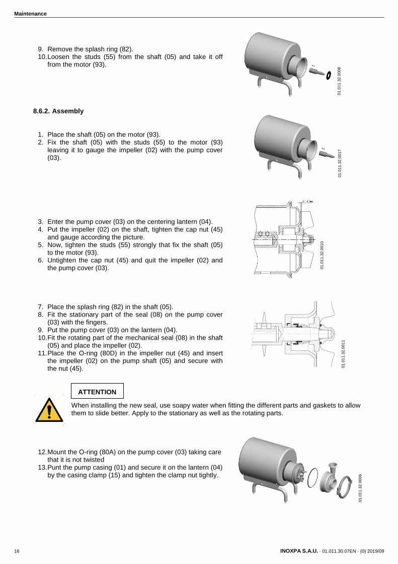
9. Remove the splash ring (82). 10. Loosen the studs (55) from the shaft (05) and take it off
from the motor (93).
8.6.2. Assembly
1. Place the shaft (05) on the motor (93). 2. Fix the shaft (05) with the studs (55) to the motor (93)
leaving it to gauge the impeller (02) with the pump cover (03).
3. Enter the pump cover (03) on the centering lantern (04). 4. Put the impeller (02) on the shaft, tighten the cap nut (45)
and gauge according the picture. 5. Now, tighten the studs (55) strongly that fix the shaft (05)
to the motor (93). 6. Untighten the cap nut (45) and quit the impeller (02) and
the pump cover (03).
7. Place the splash ring (82) in the shaft (05). 8. Fit the stationary part of the seal (08) on the pump cover
(03) with the fingers. 9. Put the pump cover (03) on the lantern (04). 10. Fit the rotating part of the mechanical seal (08) in the shaft
(05) and place the impeller (02). 11. Place the O-ring (80D) in the impeller nut (45) and insert
the impeller (02) on the pump shaft (05) and secure with the nut (45).
When installing the new seal, use soapy water when fitting the different parts and gaskets to allow them to slide better. Apply to the stationary as well as the rotating parts.
12. Mount the O-ring (80A) on the pump cover (03) taking care that it is not twisted
13. Punt the pump casing (01) and secure it on the lantern (04) by the casing clamp (15) and tighten the clamp nut tightly.
01
.01
1.3
2.0
01
1
01
.01
1.3
2.0
01
0
01
.01
1.3
2.0
01
7
01
.01
1.3
2.0
00
8
01
.01
1.3
2.0
00
6
ATTENTION

Technical Specifications
INOXPA S.A.U. · 01.011.30.07EN · (0) 2019/09 17
9. Technical Specifications
Maximum operating pressure 1.000 kPa (10 bar)
Temperature range -10ºC to 120ºC
Maximum speed 3.000 rpm (50 Hz)
3.600 rpm (60 Hz)
Materials
Parts in contact with the product AISI 316L
Other stainless steel parts AISI 304L
Seals in contact with the product EPDM (standard)
Other materials for the seal consult with INOXPA
Exterior surface finish matt
Interior surface finish Ra ≤ 0,8 μm
Mechanical seal
Type of seal: single inside seal
Stationary parts material silicon carbide (SiC) (standard)
Rotary parts material graphite (C) (standard)
Silicon carbide (SiC)
Seal material EPDM - FPM
Motor
Type Three-phase asynchronous motor, IEC B34 type, 2 or 4
Poles, IP55 protection, class F insulation
Power 0,37 to 11 kW
Voltage and frequency 220-240 V Δ / 380-420 V Υ, ≤ 4 kW
380-420 V Δ / 660-690 V Υ, ≥ 5,5 kW
9.1. NOISE LEVEL
The indicated noise levels correspond to the standard pump, with maximum impeller and shrouded motor, running at approx. 2900 rpm, at the point of best efficiency and with a motor with sufficient power.
These values were taken at a distance of 1 m from the pump and at a height of 1.6 m above the floor level. The measurements were carried out according to the standard EN 12639 / ISO 3746 Grade 3 with a tolerance of ±3dB (A).
Pump type Motor power
(kW) Sound pressure LpA
dB(A) Sound power LwA
dB(A)
SE-15 0,55 64
SE-20 2,2 69
SE-26 5,5 77
SE-28 7,5 79
SE-35 11 81 94
SE-36 15 83 97
It must be borne in mind that the noise levels can greatly increase if reducers, elbows or other fittings are installed near the pump.

Technical Specifications
18 INOXPA S.A.U. · 01.011.30.07EN · (0) 2019/09
9.2. WEIGHT
Weight (kg)
IEC 71 80 90 100 112 132 160
kW 0,25 0,55 0,75 1,1 1,1 1,5 2,2 2,2 3 4 5,5 5,5 7,5 11 11 15
SE-15 14 15 22 24 28
SE-20 30 29 31 43 49
SE-26 31 43 50 56 71 79
SE-28 36 48 55 61 76 84
SE-35 49 54 62 76 85 98 134 154
SE-36 52 57 63 88 101 136 156
9.3. DIMENSIONS
01
.01
1.3
2.0
01
8
Technical Specifications
INOXPA S.A.U. · 01.011.30.07EN · (0) 2019/09 19
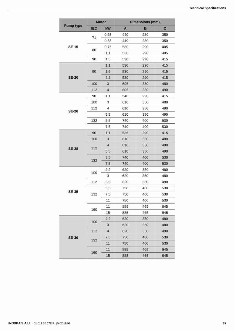
Pump type Motor Dimensions (mm)
IEC kW A B C
SE-15
71 0,25 440 230 350
0,55 440 230 350
80 0,75 530 290 405
1,1 530 290 405
90 1,5 530 290 415
SE-20
90
1,1 530 290 415
1,5 530 290 415
2,2 530 290 415
100 3 605 350 480
112 4 605 350 490
SE-26
90 1,1 540 290 415
100 3 610 350 480
112 4 610 350 490
5,5 610 350 490
132 5,5 740 400 530
7,5 740 400 530
SE-28
90 1,1 535 290 415
100 3 610 350 480
112 4 610 350 490
5,5 610 350 490
132 5,5 740 400 530
7,5 740 400 530
SE-35
100 2,2 620 350 480
3 620 350 480
112 5,5 620 350 490
132
5,5 750 400 530
7,5 750 400 530
11 750 400 530
160 11 885 465 645
15 885 465 645
SE-36
100 2,2 620 350 480
3 620 350 480
112 4 620 350 490
132 7,5 750 400 530
11 750 400 530
160 11 885 465 645
15 885 465 645

Technical Specifications
20 INOXPA S.A.U. · 01.011.30.07EN · (0) 2019/09
9.4. EXPLODED DRAWING OF HYGINOX SE PUMP
01
.01
1.3
2.0
00
9
Deta
il pum
p w
ith m
oto
r T
13
2/1
66
Technical Specifications
INOXPA S.A.U. · 01.011.30.07EN · (0) 2019/09 21
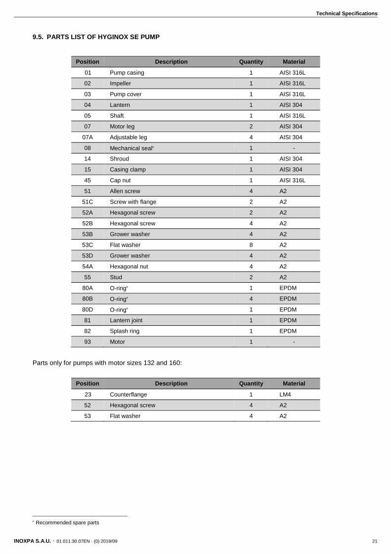
9.5. PARTS LIST OF HYGINOX SE PUMP
Position Description Quantity Material
01 Pump casing 1 AISI 316L
02 Impeller 1 AISI 316L
03 Pump cover 1 AISI 316L
04 Lantern 1 AISI 304
05 Shaft 1 AISI 316L
07 Motor leg 2 AISI 304
07A Adjustable leg 4 AISI 304
08 Mechanical seal 1 -
14 Shroud 1 AISI 304
15 Casing clamp 1 AISI 304
45 Cap nut 1 AISI 316L
51 Allen screw 4 A2
51C Screw with flange 2 A2
52A Hexagonal screw 2 A2
52B Hexagonal screw 4 A2
53B Grower washer 4 A2
53C Flat washer 8 A2
53D Grower washer 4 A2
54A Hexagonal nut 4 A2
55 Stud 2 A2
80A O-ring 1 EPDM
80B O-ring 4 EPDM
80D O-ring 1 EPDM
81 Lantern joint 1 EPDM
82 Splash ring 1 EPDM
93 Motor 1 -
Parts only for pumps with motor sizes 132 and 160:
Position Description Quantity Material
23 Counterflange 1 LM4
52 Hexagonal screw 4 A2
53 Flat washer 4 A2
Recommended spare parts

NOTES
________________________________________________________________________________
________________________________________________________________________________
________________________________________________________________________________
________________________________________________________________________________
________________________________________________________________________________
________________________________________________________________________________
________________________________________________________________________________
________________________________________________________________________________
________________________________________________________________________________
________________________________________________________________________________
________________________________________________________________________________
________________________________________________________________________________
________________________________________________________________________________
________________________________________________________________________________
________________________________________________________________________________
________________________________________________________________________________
________________________________________________________________________________
________________________________________________________________________________
________________________________________________________________________________
________________________________________________________________________________
________________________________________________________________________________
________________________________________________________________________________
________________________________________________________________________________
________________________________________________________________________________
________________________________________________________________________________
________________________________________________________________________________
________________________________________________________________________________
________________________________________________________________________________
________________________________________________________________________________
________________________________________________________________________________

INOXPA S.A.U.
Telers, 60 – 17820 – Banyoles – Spain
Tel.: +34 972 575 200 – Fax.: +34 972 575 502
How to contact INOXPA S.A.U.:
Contact details for all countries are
Continually updated on our website.
Please visit www.inoxpa.com to access the information.
01.0
11.3
0.0
7E
N (
0)
2019/0
9