Centralized Controller G-50A - Компания ... · - 1 - Mitsubishi Air Conditioni ng...
40
- 1 - Mitsubishi Air Conditioning Management System Centralized Controller G-50A Sales Manual CONTENTS 1. Appearance, basic functions and characteristics of G-50A ・・・・・・・・・・・・・・・・・・・・・・・・・・・・・・・・・・・・・・・・・・・・・ 2 2. Examples of G-50A utilization ・・・・・・・・・・・・・・・・・・・・・・・・・・・・・・・・・・・・・・・・・・・・・・・・・・・・・・・・・・・・・・・・・・・・・ 3 3. G-50A controlled air conditioners; specification; external dimension; description of control ・・・・・・・・・・・・・・・・・・ 4 4. Special considerations about the use of G-50A, due to its difference from conventional models, and the concept of the upper class and lower class ・・・・・・・・・・・・・・・・・・・・・・・・・・・・・・・・・・・・・・・・・・・・・・・・・・・ 6 5. System examples for G-50A stand-alone application, equipment address setting and power supply ・・・・・・・・・・・・・・・・・・・・・・・・・・・・・・・・・・・・・・・・・・・・・・・・・・・・・・・・ 7 6. External Input / Output functions ・・・・・・・・・・・・・・・・・・・・・・・・・・・・・・・・・・・・・・・・・・・・・・・・・・・・・・・・・・・・・・・・・・・ 9 7. System pattern at Monitoring/controlling with PC ・・・・・・・・・・・・・・・・・・・・・・・・・・・・・・・・・・・・・・・・・・・・・・・・・・・・ 12 8. Outline and difference of G-50A integrated software TG 2000A and web browser (Internet explorer) ・・・・・・・・ 13 9. System composition and address setting for connecting G-50A+ PC monitoring / controlling ・・・・・・・・・・・・・・・ 14 (include K- and A-control) 10. Air Conditioner operation control by Web browser (Internet Explorer) ・・・・・・・・・・・・・・・・・・・・・・・・・・・・・・・・・・・ 16 11. Operation management by TG-2000A (integrated software of G-50A) ・・・・・・・・・・・・・・・・・・・・・・・・・・・・・・・・・・ 19 12. Basic set-up procedures for integrated software TG-2000A ・・・・・・・・・・・・・・・・・・・・・・・・・・・・・・・・・・・・・・・・・・・ 25 13. Calculation of Air-conditioning energy charging ・・・・・・・・・・・・・・・・・・・・・・・・・・・・・・・・・・・・・・・・・・・・・・・・・・・・・ 26 14. System design flow and test run of Air-conditioning energy charging ・・・・・・・・・・・・・・・・・・・・・・・・・・・・・・・・・・・ 31 15. Check sheet of information on system registration of Air-conditioning energy charging ・・・・・・・・・・・・・・・・・・・・ 33 16. Outline of energy saving / peak cut control ・・・・・・・・・・・・・・・・・・・・・・・・・・・・・・・・・・・・・・・・・・・・・・・・・・・・・・・・・・ 34 17. Restrictions on wiring for LAN ・・・・・・・・・・・・・・・・・・・・・・・・・・・・・・・・・・・・・・・・・・・・・・・・・・・・・・・・・・・・・・・・・・・・ 36 18. License registration of optional functions ・・・・・・・・・・・・・・・・・・・・・・・・・・・・・・・・・・・・・・・・・・・・・・・・・・・・・・・・・・・ 38 19. Method for initial registration on G-50A’s own and on PC monitoring with initial setting tool ・・・・・・・・・・・・・・・ 39
Transcript of Centralized Controller G-50A - Компания ... · - 1 - Mitsubishi Air Conditioni ng...

- 1 -
Mitsubishi Air Conditioning Management System
Centralized Controller G-50A
Sales Manual
CONTENTS
1. Appearance, basic functions and characteristics of G-50A ・・・・・・・・・・・・・・・・・・・・・・・・・・・・・・・・・・・・・・・・・・・・・ 2
2. Examples of G-50A utilization ・・・・・・・・・・・・・・・・・・・・・・・・・・・・・・・・・・・・・・・・・・・・・・・・・・・・・・・・・・・・・・・・・・・・・ 3
3. G-50A controlled air conditioners; specification; external dimension; description of control・・・・・・・・・・・・・・・・・・ 4
4. Special considerations about the use of G-50A, due to its difference from conventional models,
and the concept of the upper class and lower class ・・・・・・・・・・・・・・・・・・・・・・・・・・・・・・・・・・・・・・・・・・・・・・・・・・・ 6
5. System examples for G-50A stand-alone application,
equipment address setting and power supply ・・・・・・・・・・・・・・・・・・・・・・・・・・・・・・・・・・・・・・・・・・・・・・・・・・・・・・・・ 7
6. External Input / Output functions ・・・・・・・・・・・・・・・・・・・・・・・・・・・・・・・・・・・・・・・・・・・・・・・・・・・・・・・・・・・・・・・・・・・ 9
7. System pattern at Monitoring/controlling with PC ・・・・・・・・・・・・・・・・・・・・・・・・・・・・・・・・・・・・・・・・・・・・・・・・・・・・ 12
8. Outline and difference of G-50A integrated software TG 2000A and web browser (Internet explorer) ・・・・・・・・ 13
9. System composition and address setting for connecting G-50A+ PC monitoring / controlling・・・・・・・・・・・・・・・ 14
(include K- and A-control)
10. Air Conditioner operation control by Web browser (Internet Explorer)・・・・・・・・・・・・・・・・・・・・・・・・・・・・・・・・・・・ 16
11. Operation management by TG-2000A (integrated software of G-50A) ・・・・・・・・・・・・・・・・・・・・・・・・・・・・・・・・・・ 19
12. Basic set-up procedures for integrated software TG-2000A ・・・・・・・・・・・・・・・・・・・・・・・・・・・・・・・・・・・・・・・・・・・ 25
13. Calculation of Air-conditioning energy charging ・・・・・・・・・・・・・・・・・・・・・・・・・・・・・・・・・・・・・・・・・・・・・・・・・・・・・ 26
14. System design flow and test run of Air-conditioning energy charging ・・・・・・・・・・・・・・・・・・・・・・・・・・・・・・・・・・・ 31
15. Check sheet of information on system registration of Air-conditioning energy charging ・・・・・・・・・・・・・・・・・・・・ 33
16. Outline of energy saving / peak cut control・・・・・・・・・・・・・・・・・・・・・・・・・・・・・・・・・・・・・・・・・・・・・・・・・・・・・・・・・・ 34
17. Restrictions on wiring for LAN ・・・・・・・・・・・・・・・・・・・・・・・・・・・・・・・・・・・・・・・・・・・・・・・・・・・・・・・・・・・・・・・・・・・・ 36
18. License registration of optional functions ・・・・・・・・・・・・・・・・・・・・・・・・・・・・・・・・・・・・・・・・・・・・・・・・・・・・・・・・・・・ 38
19. Method for initial registration on G-50A’s own and on PC monitoring with initial setting tool ・・・・・・・・・・・・・・・ 39

- 2 -
1. Appearance, basic functions and characteristics of G-50A (1) Appearance and functionality This controller has higher functionality than any previous centralized controllers, and this product is the first in the industry to support the web. One G-50A unit can control and monitor up to 50 indoor units. This controller can be controlled and operated by browser software (Internet Explorer ver. 5 or above) from a PC connected via LAN or telephone lines. Other than the basic operation of the packaged air conditioners, it can support various functions required for air conditioning controlling such as “Annual schedule operation” “Air-conditioning energy charging” “Energy-saving operation”, by adding optional functions. (2) Basic Functions Appearance G-50A unit Major functions
ON/OFF Operation mode change Temperature setting Air velocity change
Operation and setting of the air conditions
Airflow direction setting Operation status (ON/OFF)
Operation mode monitor Temperature monitor Failure monitor Air velocity change
Monitor air conditioners
Airflow direction change Scheduling function Weekly schedule operation possible
External input/ output is possible
ON/OFF and abnormal conditions can be output to outside; emergency stop and ON/OFF can be input from outside.
(3) Characteristics 1) Besides the monitor/control from the G-50A unit, remote monitor/
control from a PC is also possible. (This is an optional function and requires input of a separate license number.)
This has a web server function, and the operation control can be made from a PC connected through LAN or public phone lines. Using a PC browser (Internet Explorer Ver.5 or above), you can easily build a centralized monitor system for air conditioners. You can confirm the operation status and make sure the power is off without walking to the remote controller location or patrolling to the far away sites. This means you can improve the efficiency of air conditioning control work and save energy through a thorough operation control. 2) You can control up to 2000 indoor units using special integrated
software. (This is an optional function and requires input of a separate license number.)
If you use G-50A special integrated software (PAC-TG2000A), you can consolidate data from all the G-50A units, and control the operation of up to 2000 units from a PC. Furthermore, floor plans can be drawn, and operation status can be indicated for each floor or for each tenant. 3) Annual schedule management is possible. (This is an optional function and requires input of a separate license number.) The standard functions include a weekly schedule function, but you can also register annual schedule on a PC as an option, and you can have 7 different patterns for days of the week, plus 5 patterns of schedule can be set on 50 special days per year. By having thorough control, you can achieve a tremendous energy-saving, unmanned operation on a day-to-day basis, and automatic operation of air conditioning. * Once a license for annual schedule is registered, G-50A unit cannot set a schedule. It has to be set and registered only on PC. 4) Electric power apportionment information can be obtained to calculate air conditioning charge for each area. (Optional function. A separate license number has to be input.) Using electric power apportionment function (optional), you can enter the electric power apportionment data for each indoor unit into a PC in CSV format. By manually inputting the total power usage, customer can have a simplified power usage count for each tenant. * The air conditioning cost calculation method use by this integrated centralized control software TG-2000A is the Mitsubishi proprietary general
electric power apportioning method. Depending on each country’s laws and regulations, etc., there may be cases these measured charges cannot be used for certificate of transaction.
5) With the addition of the designated sequencer and electric energy count software, air conditioning charge can be automatically calculated. (This is an optional function and requires input of a separate license number.)
In addition to the system described above, if you add a sequencer (MESLEC-Q series) and power usage count software (optional), you can have power usage reading from the watt hour meter or electric power count by PC direct connect (RS-485WHM). Based on that information and G-50A integrated software (TG-2000A), you can calculate the power usage count per tenant. * The air conditioning cost calculation method use by this integrated centralized control software TG-2000A is the Mitsubishi proprietary general
electric power apportioning method. Depending on each country’s laws and regulations, etc., there may be cases these measured charges cannot be used for certificate of transaction.
6) Energy-saving operation mode will help reduce the power consumption without harming the comfort. (This is an optional function and requires input of a separate license number.) Energy-saving operation mode (optional) will enable rotated fan operation and heating/cooling power save operation. Energy can be saved in a way to meet the customer’s demand. * With this function, air in-take temperature and room temperature setting will be considered, and the room temperature setting will be shifted to
a higher side during cooling period and to a lower side during heating period at a fixed time interval. For instance, if the air intake temperature is set at 24°C and the room temperature setting is 22°C for air conditioning, the room temperature setting will be altered to 24°C. If the air intake temperature is 28°C and room temperature setting is 22°C, there will be no change.
7) In case of abnormality, a mail will be sent to cell phones or PCs. (This is an optional function and requires input of a separate license number.) If there is something wrong with the air conditioning unit, the abnormality will be notified to the designated mail address. You can be notified of the abnormality wherever you are, and take necessary actions to recover the system quickly.
Software for PC monitor/control and necessity oflicense certification Browser software
(PC software) License
certificationInternet Explorer Ver.5 ~
Monitor and control by PC TG2000A
(optional product)
Necessary
Internet Explorer Ver.5 ~
Annual scheduling function TG2000A
(optional product)
Necessary
Air-conditioning energy charging
TG2000A (optional product) Necessary
Energy saving operation function
TG2000A (optional product) Necessary
* License certification : License registration is required to use the optional function ( to be charged).
Remote control fromWeb browser
Public circuit Router
City MultiWatt-hour meter
Air conditioningmanagement

- 3 -
2. Examples of G-50A utilization (1) Make the control work more efficient by remote control and
operation. 1) While you are at your desk doing paper work, you can monitor and control
air conditioners from a PC on your desk. 2) When you leave the office for the day, you don’t have to check every
remote controller to make sure the power is off. ON/OFF operation can be made collectively from a PC.
3) You can monitor and control air conditioners in remote buildings (via LAN or public phone lines).
4) If you take a lap top PC and PHS with you, you can monitor and control the system away from your office.
5) You can prohibit ON/OFF operation, temperature setting change, and operation mode change by local remote controllers.
(2) Energy saving is possible through annually schedule operation 1) By adding optional functions, you can have extended weekly schedule
operation and annual schedule operation. (You have to specially register the setting in a PC.)
2) Besides ON/OFF operation, you can schedule operation mode and temperature settings by the unit of minutes.
3) Prohibition of ON/OFF operation, temperature setting change, and operation mode change can be set to the minute so that you can control temperature settings well and never forget to turn off the switch.
Example 1: ON/OFF switch can be prohibited during night, making the air conditioning unit inoperable during night.
Example 2: Fix the room temperature at 25°C for air conditioning during the intermediate season.
Example 3: Energy-saving operation is possible by making the unit inoperable during lunch break or setting the room temperature on a higher side and fixing it.
4) Shops and stores can have air conditioning operation adjusted by pre-setting the room temperature depending on the estimated turnout of visitors for the day.
5) The day’s schedule can be adjusted each day, and air-conditioning in a meeting room can start /stop at a pre-set time.
(3) Air conditioning charge data can be freely processed on a PC.
1) Air conditioning charge can be calculated as an option. 2) Air conditioning charge data can be edited and processed on a PC. 3) If you build a PC network, you can get the electric power apportioned
charge data from a remote location and the transaction can be made without human intervention such as transferring or posting data.
4) If the electric power apportionment function is used, you can confirm the integrated running time of each air conditioning unit.
(4) With the existing air conditioners, energy saving can be accomplished.
1) Energy saving operation will enable energy saving easily.
(5) By eliminating the use of local remote controllers, the interior aesthetics will be enhanced.
1) If you are bothered by the design of a remote controller or wiring in the room, you can get rid of them.
2) In a lobby or a place with high traffic, or if you don’t want students or patients to handle a remote controller in a classroom or in a hospital, you can eliminate use of a local remote controller.
(6) Various interlock operation is possible using a sequencer. 1) With an interlock to “key lock” and “human thermal sensor” as an
energy-saving measure, you can stop the operation of an air conditioning unit when the room is locked or there is nobody inside.
2) Detecting the upper limit and lower limit of the local humidity sensor or temperature sensor, cooling/heating and dry operation can be activated or stopped.
(7) Notice of error code via mail at malfunction 1) In case of a machine trouble, the unit number with the faulty operation
and the code number for the trouble will be sent by email. Since the type of trouble can be promptly communicated and the spare parts can be arranged in advance, a swift recovery will be possible. In case of “Mr. Slim”, the code will be displayed on G-50A in 4 digits. Basically they are same as Building Multi, but there is one code unique to Mr. Slim, that is “68**” for a Mr. Slim indoor/outdoor unit communication error.
G-50A unit On the web
TG-2000A
License registration(No)
Weeks
× ×
License registration(Yes)
× Weekly/ annual
Weekly/ annual
If the annual schedule license is registered, the standard weekly schedule function on the main unit will become inoperable. Extended weekly/annual schedule example
The optional software can store electricity billing data calculatedfor each tenant. All I have to do is retrieve the data into spreadsheet software and process into bills. It is very convenient and efficient.
(G-50A provides a billing system in each building)G-50AMaintenance Company
Bill
Case: 1Remote controllers and wires can be destructive to interior design.
Case: 2Remote controllers need to be avoided or concealed in high-traffic areas such as building lobbies.
Case: 3Remote controller groupings and locations are subject to frequent change in locations such as tenant buildings
I can check the nature of troubles without asking customers. It is convenient.
•Air conditioners of different outlets are constantly monitored. Reports are provided to the designated e-mail addresses in the event of troubles.
• Quick restoration is possible thanks to the ability to understand the nature of troubles early.
Shop
Office
CoffeeShop
G-50A
G-50A
G-50AG-50AG-50A
G-50A
G-50A
G-50A
G-50A G-50A
G-50AG-50A

- 4 -
3. G-50A controlled air conditioners; specification; external dimension; description of control (1) G-50A controlled air conditioners
Energy-saving control (Energy-saving control items) Type (the series name)
Control/
management
Electric power apportioned charge
(Electric energy pulse count) Fan speed Room temperature setting
Capacity saving
CITY MULTI Y Series (8~20HP) ±2°C (60~90%) CITY MULTI Super Big Y Series (24~30HP) ±2°C (60~90%) CITY MULTI R2 Series (8~20HP) ±2°C (60~90%) CITY MULTI WR2 Series (8, 10HP) ±2°C (60~90%) CITY MULTI WY Series (8, 10HP)
*1 ±2°C (60~90%)
CITY MULTI S Series ±2°C Mr. Slim Series (A-control) *3 (Each billing unit needs a watt hour meter installed.) ±2°C x Split Type Air Conditioner (A-control) x K-Control Series *2 (Each billing unit needs a watt hour meter installed.) ±2°C x Lossnay (GUF Series : OA processing Units) (Incase it’s set as an indoor unit) Lossnay (LGH Series) (Each billing unit needs a watt hour meter installed.)
x x x
*1 Pump and cooling tower power supply cannot have apportioned charge. However, a watt-hour meter may be mounted to each billing unit for solution.
*2 Due to K-control type, individual items cannot be prohibited or permitted. It also requires K-control converter. *3 Requires A-control adapter. (2) G-50A unit specification
Item Description Product dimension 300mm(width) x 120mm(height) x 79mm(depth) * Thickness of the exposed section is 22mm. Weight 1.0 kg Power source DC24V, 12V * Power is fed from a power supply unit for transmission lines. Rated current consumption 0.2A Rated power consumption 6W CPU ROM 14M bytes (flash memory) RAM 16M bytes (SDRAM) Display Liquid crystal 128 x 160 dots Batch ON/OFF LED x 1 Network M-NET, Ethernet (10BASE-T), external output/input terminals (input 4, output 2, A relay up to 0.9W can be connected.)
(3) G-50A Exterior view
G-50A
Mounting plate

- 5 -
(4) G-50A unit control functions
Function Description Indoor units and Lossnay Up to 50 sets can be connected. (including interlocked units)
No. of indoor units in one group 1~16 sets (Same for Lossnay with no interlocking. However, you cannot have both indoor units and Lossnay in the same group.)
No. of remote controllers in one group 0 ~ 2 sets
System controllers in one group 0 ~ 4 sets (Total number of remote controllers and system controllers in one group should not exceed 4.)
No. of manageable units
Interlocked units
• Number of interlocked units (Lossnay) connected to one interlocking unit (indoor unit) is 1.
• Number of interlocking units (indoor units) that can be registered in one interlocked unit (Lossnay) is 16.
Power ON/OFF All or group of units can be turned ON/OFF collectively. Operation mode
Operation mode can be switched between cooling/dry/heating/fan/automatic for all or group of units collectively. (If the group has only Lossnay’s, heat exchange/normal/automatic in ventilation mode can be switched over.)
Air velocity A 4-step change can be made for a group or all of units collectively. (Certain models have only 2 or 3 steps.)
Room temperature setting
Room temperature can be set collectively for all or group of units. (The room temperature range varies depending on the type of units to be connected.) Cooling Heating Automatic Temperature range 19ºC ~ 30ºC 17ºC ~ 28ºC 19ºC ~ 28ºC
Airflow direction setting
The airflow direction can be changed among 4 different vertical directions and swings for all or group of units collectively. (The available airflow directions can be different depending on the model.)
ON/OFF of interlocked units (Lossnay)
In case there is an interlocked unit (Lossnay), ON (high or low) and OFF switchover can be made for all or group of units collectively. (However, an interlocked unit cannot select a ventilation mode.)
Prohibition of control from local remote controllers
You can choose and set some items that cannot be controlled from the local remote controllers for all or group of units collectively. (Such items include ON/OFF, operation mode, room temperature, and filter sign.)
Timer operation
A weekly schedule operation can be made for a group of units. • 4 types of operation patterns (P1 – P4) can be set weekly. (P4 is the prohibition of control
from the local remote controller.) • ON/OFF can be set 3 times per day. • Room temperature setting and setback operation can be interlocked to the timer operation.
Filter sign reset Filter sign display reset can be done for all or group of units collectively.
Operation
External input Emergency stop, ON/OFF, prohibit/permit can be set from outside collectively. (A separate external input/output adaptor is needed.)
ON/OFF (batch) A batch ON/OFF lamp will indicate one or more group is running or the entire group has stopped.
Operation status per group ON/OFF, operation mode, air velocity, room temperature setting, airflow direction, ON/OFF of interlocked units, time operation valid/invalid will be indicated for each group.
Filter sign Filter cleaning sign will indicate the timing of cleaning for each group Prohibit local control The content of the prohibition by this unit or another unit will be displayed.
Trouble occurrence Address of the unit having trouble and its error code, and address of the unit whose trouble has been detected will be displayed.
Standard functions
Monitor
External output Batch ON/OFF and any abnormality signals can be output to outside. (A separate external input/output adaptor is needed.)
Group setting Indoor units, Lossnay, remote controllers and lower class system controllers will be grouped together and registered.
Control
Interlocking setting Indoor unit as an interlocking unit will be registered in an interlocked unit (Lossnay).
Trouble history monitor Up to 64 past troubles will be stored in the memory. (The newest trouble is on top of the list, totaling to 64 of them in a chronological order)
Initial setting functions
Monitor Refrigerant system monitor For each outdoor unit, actually connected indoor units can be confirmed.
Transmission and reception of prohibition
In case operation by a local remote controller is to be prohibited, whether it should be commanded from the main unit or from another controller will be determined.
System Prohibition transmission target
In case of an operation prohibit, whether it should be only for a local remote controller, or it should include other controllers will be determined.
Connection /interlocking information
Grouping information and interlock setting information will not be lost even when the power is off.
Trouble history It would not be lost even when the power is off. Timer operation The schedule information for each group will not be lost even when the power is off.
Others
Data backup
Current time
Even when the power is off, the time clock will be run by the internal condenser for about one week. (Recharging the internal condenser will take about one day. Battery replacement is not necessary.)

- 6 -
4. Special considerations about the use of G-50A, due to its difference from conventional models, and the concept of the upper class and lower class
(1) Special considerations about the use of G-50A, due to its difference from conventional models 1) A group of indoor units cannot be controlled by more than two G-50A units. You cannot have multiple connections of
G-50A within the same group. → If you want to have 2 separate centralized control within the same group, use one G-50A and one system remote controller, or something equivalent. (The reason is described below in the concept of upper class and lower class.)
2) G-50A cannot be used together with the system controller like MJ-300 that are higher in class than G-50A. (2) The concept of upper class and lower class pertaining to G-50A *Upper class system controller and lower class system controller This unit (G-50A) always functions as an upper class system controller. It can not be treated as a lower class system controller. • Upper class system controller (upper class SC)
A system controller that encompasses the control scope of all other system controllers is called “upper class system controller”. Also, if there is only one controller in the entire system, that controller becomes the upper class system controller. Only the upper class system controller needs to have a group setting and interlocking operation setting.
• Lower class system controller (lower class SC) A controller whose entire control area is controlled by an upper class system controller is called a lower class system controller.
The following group settings cannot be made. • A group outside the control of the upper class system controller is controlled by a lower class controller. • Two or more system controllers control the same group of units. Therefore, G-50A always has to be an upper class system controller. G-50A can never be used as a lower class system controller.
Control scope ofupper class SC
Control scope of lower class SC
Group Group
Group This unit is for upper class SC use only. It cannot be used as a lower class SC and controlled by upper class SC (gateway and others).
Upper class system controller
Lower classsystem controller
GroupGroup Group
Upper class system controller 1
Upper classsystem controller 2
GroupGroup Group

- 7 -
5. System configuration examples for G-50A stand-alone application, equipment address setting and power supply
(1) G-50A stand alone system configuration (no connection to PC, monitor and operation to be done by G-50A unit)
(Example 1) When air conditioners and Lossnay are mixed in the system
Power supply lines are omitted from this diagram, showing only the transmission lines. This shield for M-NET centralized system transmission lines should be grounded at a single point through the transmission line power supply unit. Indoor/outdoor transmission lines should be grounded for each outdoor unit system. M-NET outdoor unit centralized control switch (SW2-1) should be always “ON”. (2) Address setting for equipment
Address setting method Address
Indoor unit The lowest number should be given to the indoor unit functioning as the parent unit within the same group. Give the serial numbers to the indoor units in the same group.
1 ~ 50
Outdoor unit Take the lowest number of indoor unit address within the same refrigerant system and add 50 to it. 51 ~ 100 Outdoor auxiliary unit (BC controller, etc.)
Take the address of the outdoor unit within the refrigerant system and add 1 to it. 52 ~ 100
Lossnay After all the indoor units are given the address, choose any number as address. 1 ~ 50
M-NET remote controller Take the lowest number of indoor unit (parent unit) address in the same group and add 100 to it. However, in case of a subordinate remote controller, add 150 to it.
101 ~ 200
MA type remote controller Address setting is not necessary. In case of 2 remote controller operation, however, main/subordinate switching setting is necessary.
−
K-control indoor unit After all the M-NET indoor units (including Lossnay) are assigned a number, the next number should be set for K-control indoor units.
1 ~ 50
K-control remote controller
Take the lowest number given to the K-control indoor unit (parent unit) in the same group, and use the same address.
1 ~ 50
K-transmission converter The lowest number of the K-control indoor unit + 200 should be used as address. 201 ~ 250
11 12
K-control transmission
converter 211
PAC-SC25KAA 058
TB7 TB3
K 11 (Group number)
Group 11
13 14
K 13 (Group number)
Group 13K-control
outdoor unit
TB7 TB3
M-NET outdoor unit BC controller
007 008
ME 106
Group 3
009 010
LR 109
Group 4
Lossnay remote controller
TB7 TB3
M-NET outdoor unit
057
051
Centralized control system
Indoor/outdoor system
001 002 003 004 005 006
Lossnay Lossnay
Lossnay
ME ME ME
000 LAN Centralized controller
Model G-50A Power supply unit for transmission lines (option)Model PAC-SC50KUA
(Example 2) When only Lossnay are in the system
001 002
LR
Group 1
003 004
LR
Group 2
Lossnay Lossnay
Centralized controller Model G-50A
000 LAN
Transmission line power supply extension unit (option)Model PAC-SF46EPA
Power supply unit for transmission lines (option)Model PAC-SC50KUA
Lossnay remote controller 101
Lossnay remote controller 103
Lossnay Lossnay
Indoor unit Local remote controller M-NET type : PAR-F27ME(A) PAC-SE51CR(A) PZ-52SF/52KF2(LR) MA type : PAR-20MA(A) PAR-FA(FL)31MA M-NET transmission line K-control transmission line MA type remote control line
Numbers in show address numbers.
Group 1 Group 2

- 8 -
(3) G-50A power supply 1) In case a transmission line power supply unit is used. (connected to centralized control transmission lines)
Transmission line power supply unit
Maximum number of G-50A connection in one system Remarks
1 set
Other system controllers (PAC-YT40ANRA, etc.) cannot be connected to centralized control system transmission lines on the outdoor unit TB7 side. In such a case, the controller should be connected to indoor/outdoor system transmission lines.
PAC-SC50KUA
2 sets
• When only one G-50A is connected. Up to 3 other system controllers can be connected to the centralized
control system transmission lines. • When 2 of G-50A are connected. (When the system of 50 or less indoor units is divided into two
groups, and each is controlled by G-50A.) Only one other system controller can be connected to the centralized
control system transmission lines. 2) Points to notice when connecting to indoor/outdoor transmission lines • The system controllers that can be connected to indoor/outdoor transmission lines are: G-50A, MJ-103MTR-A, PAC-YT34STA,
PAC-SF44SRA, PAC-SC30GRA. However, the outdoor unit City Multi S <PUMY-P Series> cannot have a system controller connected to indoor/outdoor transmission lines. Also, in case connecting a system controller to indoor/outdoor transmission lines, the system controller becomes unable to control once the outdoor unit power supply is shut off. Please give enough precaution to that point. In case you use the electric power apportioned charging ("Air Con Electricity Charge") function, as an option to the centralized controller G-50A, do not connect G-50A to indoor/outdoor transmission lines. • Up to 3 system controllers can be connected within the same refrigerant system, and only one G-50A unit can be one of those
3. In that case, the number of connectable indoor units will be 4 less. If other system controllers are used, the number of maximum connection per group will be 2 less per system controller.

- 9 -
G-50 (CN2)
6. External I/O functions External I/O functions Using an external I/O adapter (PAC-YG10HAA), you can send contact signals and pulse signals to control a batch ON/OFF of air conditioners connected to G-50A. (1) External input Using energized contact signals (DC12V or DC24V) from outside, it can operate emergency stop/normal, ON/OFF, prohibit/permit of local remote controllers for all the air conditioners under its control.
Function setting switch No External input signal functions No. 6 No. 7 Remarks
1 External input signals not to be used (default at shipment) OFF OFF
2 Emergency stop/normal will be executed by level signals.
OFF
ON
During emergency stop, ON/OFF by a local remote controller, and ON/OFF and prohibit/permit change by G-50A will be prohibited.
3 ON/OFF will be executed by level signals. ON OFF ON/OFF by a local remote controller, and ON/OFF and prohibit/permit change by G-50 will be prohibited.
4 ON/OFF and prohibit/permit will be executed by pulse signals. ON ON When contact is ON, the pulse width should be 0.5~1
second. (2) Level signals and pulse signals (A) Level Signals (B) Pulse signals Example: case of ON/OFF (3) External input specification
CN2 Lead wire Emergency stop/normal level signals ON/OFF level signals ON/OFF, prohibit/permit pulse signals No.5 Orange Emergency stop/normal input ON/OFF input On input No.6 Yellow Not used not used Off input No.7 Blue Not used not used Local remote controller prohibit input No.8 Gray Not used not used Local remote controller permit input No.9 Red External DC power source +12V or +24V
A) Level signals 1) When emergency stop/normal signal is selected, and the external input signal contact changes from “OFF” to “ON”,
“normal” changes to “emergency stop”. When the contact changes from “ON” to “OFF”, “emergency stop” changes to “normal”.
2) When ON/OFF signal is selected, and the external input signal contact changes from “OFF” to “ON”, the operation mode changes from “OFF” to “ON”. When the contact changes from “ON” to “OFF”, the operation mode changes from “ON” to “OFF”.
(B) Pulse signals 1) While the machine is running, if “ON” signal is input, it remains “ON”. (Same for stop, prohibit, and permit.) 2) When a local remote controller is prohibited, it prohibits the operation of ON/OFF, operation mode, room temperature
setting, and filter reset by a local remote controller. 3) Pulse width (time duration while the contact is on) should be 0.5 ~ 1 second.
(4) Recommended circuit example (A) Level signals (B) Pulse signals
1) Relays, DC power source, and extension cables should be locally procured separately. 2) Maximum length of the connection cable extension should be 10m. (Use a cable thicker than 0.3mm2.) 3) If the cable is too long, cut it to size, and insulate the exposed portion with a tape.
* Same for prohibit/permit input.
Contact ON Contact OFF OFF ON OFF
Contact ON Contact OFF Normal Normal OFF ON OFF
Contact ON Contact OFF
Contact ON Contact OFF
0.5~1 sec.
0.5~1 sec.
CN22
X1
Main Max. 10m
Red
Orange ON/OFF, or emergency stop Power supply (*1) (DC12V or DC24V)
5
6
7
8
9 CN22
X1
Main Max. 10m
Red
OrangeYellowBlue
Purple
Power supply (*1)(DC12V or DC24V)
5
6
7
8
9
X2
Y1Y2
X1
Y1
X2
Y2
ON OFF
ProhibitPermit
X1
Emergency stop
Signal 1 (ON) Signal 2 (OFF)
Connector of external I/O adapter (PAC-YG10HAA) To be connected to G-50A (CN2)
G-50A(CN2)

- 10 -
If [Emergency stop mode (level input)] is selected, a batch stop can be made by level signals. During a batch stop, G-50A and remote controller’s ON/OFF operation will be prohibited. If [ON/OFF mode (level input)] is selected, a batch on and off can be made by level signals. In this mode, all the air conditioners to be connected to G-50A will always be a batch on or a batch off, and G-50A and remote controller’s ON/OFF operation will be prohibited. If [ON/OFF/control prohibit/control permit (pulse input)] is selected, batch on, batch off, local control prohibit, and local control permit can be made by pulse signals. In this mode, a remote controller can control the unit freely, except when the pulse signals are being input.
Contact ON
Contact OFF
Normal Emergency stop Normal
123456789
Connected G-50A (CN2)
DC12V
Emergency stop/Normal
Contact ON
Contact OFF
OFF ON OFF
Connected G-50A (CN2)
DC12V
ON/OFF
Connected G-50A (CN2)
DC12V
123456789
123456789
OFF
Prohibit
ON
Permit
: Pulse oscillator
Contact ON
Contact OFF
OFF ON OFF
Contact ON
Contact OFF
ON
OFF
0.5~1.0 sec.
Contact ON
Contact OFF
Permit Prohibit Permit
Contact ON
Contact OFF
Prohibit
Permit
0.5~1.0 sec.

- 11 -
External output functions (1) External output When one or more air conditioning unit is running, ON signal is output; and when one or more air conditioning unit has trouble, “Abnormality generated” is output. (2) External output specification
CN2 Lead wire Terminal No. 1 Green External output common GND (external DC power supply GND) No. 2 Black ON/OFF No. 3 Brown Abnormal/normal
1) “ON” will be output even during an abnormal occurrence. (3) Recommended circuits example When relays are activated. 1) While it’s on, abnormal occurrences will turn each element on. 2) The connection cable extension should be 10 m at maximum. 3) Relay, lamps, diode, extension cables should be arranged locally.
L1: Operation indicator lamp L2: Abnormality indicator lamp
CN2
2
3
4
1
Z1
Z2
Z1
Z2 L2
L1
Main unit Max. 10m
Black Brown
Green
Diode (*2)
Powersupply
(*1)
For relays Z1 and Z2, please use parts that conform to following specification. Control coil Rated voltage : DC12V, DC24V Power consumption : 0.9W or below (*1) Please arrange a power supply separately, which fits the
relay to be used. (DC12V or DC24V) (*2) Please make sure you insert diodes on both ends of the
relay coil.

- 12 -
7. System Pattern at Monitoring/Controlling with PC The monitoring method by a PC (software used) can roughly be classified into two patterns.
Within 1000 indoor units : Pentium 4 1.8GHz or faster 1001 indoor units or over : Pentium 4 1.8GHz or faster (Case of temp. trend use : 2.8GHz or faster)
(1) Monitoring/controlling using Web browser (Internet Explorer) (2) Monitoring/controlling using G-50A integrated software (option) For the difference of the function, refer to the relating page (Comparison of software). LAN is used to connect G-50A and PC. While remote monitoring can be performed via public telephone line. System image
(1) Monitoring/controlling using Web browser (Internet Explorer)Your PC for business use can be utilized as a remote controller.
Common use with PC for ordinary business use
Centralized controller G-50A
control screen
Individual remote controller screen
Home page
TG = Integrated 2000 = Controls indoor units up to 2,000 sets
(1) Monitoring/controlling using G-50A integrated software (option)TG-2000A (Optional software exclusive for air conditioning use)
Annual schedule Air conditioning electric charge calculation Energy saving control
PC for integrated control
Dialup router
Monitoring/controlling by Web browserMonitoring/controlling by G-50A integrated software Error e-mail transmission
Telephone circuit

- 13
-
8.
Out
line
and
Diff
eren
ce o
f G-5
0A In
tegr
ated
Sof
twar
e TG
200
0A a
nd W
eb B
row
ser (
Inte
rnet
Exp
lore
r)
Mon
itorin
g/co
ntro
lling
by
G-5
0A in
tegr
ated
sof
twar
e (o
ptio
n)
Mon
itorin
g/co
ntro
lling
by
Web
bro
wse
r (In
tern
et E
xplo
rer)
Sum
mar
y 1.
Plu
ral G
-50A
uni
ts c
an b
e di
spla
yed
colle
ctive
ly an
d co
ntro
lled
on th
e sc
reen
.
The
indo
or u
nits
can
be
disp
laye
d an
d co
ntro
lled
colle
ctive
ly up
to 2
000
sets
.
The
G-5
0A u
nit c
an b
e co
nnec
ted
up to
40
sets
. 2.
At
the
elec
tric
pow
er a
ppor
tione
d ch
argi
ng,
or e
nerg
y sa
ving
fun
ctio
n ut
iliza
tion,
the
G-5
0A in
tegr
ated
sof
twar
e is
nee
ded
esse
ntia
lly.
1. E
ach
G-5
0A u
nit c
an m
onito
r and
con
trol t
he in
door
uni
ts u
p to
50
sets
.
Alth
ough
the
G-5
0A u
nit
can
be c
onne
cted
up
to 2
55 s
ets,
the
scr
een
disp
lays
the
indo
or u
nit u
p to
50
sets
in a
uni
t of G
-50A
.
Peru
sal s
oftw
are
whe
n us
ing
optio
nal f
unct
ion
Ann
ual s
ched
ule
func
tion
(R
equi
res
licen
se re
gist
ratio
n se
para
tely
) * w
ith c
opyi
ng fu
nctio
n
(Req
uire
s lic
ense
regi
stra
tion
sepa
rate
ly) *
with
out c
opyi
ng fu
nctio
n E
lect
ric p
ower
app
ortio
ned
char
ging
(Req
uire
s lic
ense
regi
stra
tion
sepa
rate
ly)
x
Ene
rgy
savi
ng c
ontro
l fun
ctio
n
(Req
uire
s lic
ense
regi
stra
tion
sepa
rate
ly)
x
Dat
a up
datin
g A
utom
atic
upd
atin
g of
dat
a Th
e da
ta is
aut
omat
ical
ly u
pdat
ed w
ith 1
min
ute
inte
rval
for
oper
atio
n st
atus
an
d 3
min
utes
inte
rval
for a
bnor
mal
sta
tus.
Man
ual u
pdat
ing
of d
ata
At c
hang
ing
the
scre
en o
r con
trol,
the
data
is u
pdat
ed.
PC
ope
ratin
g en
viro
nmen
t In
stal
led
excl
usiv
ely
for a
ir co
nditi
onin
g co
ntro
l A
PC
for
bus
ines
s ap
plic
atio
n ca
n be
usa
ble
com
mon
ly i
f sa
tisfy
ing
the
follo
win
g sp
ecifi
catio
ns.
CP
U
With
in 1
000
indo
or u
nits
: P
entiu
m 4
1.
8GH
z or
fast
er
1001
indo
or u
nits
or o
ver
: Pen
tium
4
1.8G
Hz
or fa
ster
(C
ase
of te
mp.
tren
d us
e : 2
.8G
Hz
or fa
ster
)
Pen
tium
133
MH
z or
mor
e
OS
W
indo
ws
2000
/XP,
P
rofe
ssio
nal (
*) E
nglis
h ve
rsio
n W
indo
ws
98/M
e/20
00/X
P, In
tern
et E
xplo
rer5
.0 o
r mor
e (J
ava
VM
5.0
or m
ore)
H
DD
4G
B o
r m
ore
of C
driv
e fre
e sp
ace
nece
ssar
y.
Whe
n us
ing
the
trend
fu
nctio
n, t
he d
rive
used
for
aut
omat
ic o
utpu
t m
ust
have
the
fol
low
ing
free
spac
e ac
cord
ing
to th
e nu
mbe
r of g
roup
s.
200
grou
ps =
2G
B, 5
00 g
roup
s =
5GB
, 100
0 gr
oups
= 1
0GB
, 200
0 gr
oups
= 2
0GB
.
Mem
ory
256M
Byt
e or
mor
e 64
MB
yte
or m
ore
Dis
play
reso
lutio
n 10
24 x
768
or m
ore
1024
x 7
68 o
r mor
e *N
ote:
Win
dow
s XP
Hom
e E
ditio
n ca
n no
t be
used
.
Scr
een
disp
layi
ng o
pera
tion
stat
us o
f all
in
door
uni
ts
Pla
n
Rem
ote
cont
rolle
r con
trol s
cree
n
Blo
ck s
cree
n
Not
app
licab
le

- 14 -
9. System Composition and Addresses at monitoring/controlling connecting G-50A + PC (K- and A-control included)
(1) IP address of G-50A and PC Address setting method IP address
IP address 192.168.1.1 ~ 192.168.1.40 G-50A Sub-net mask
Set by G-50A unit or initial setting tool 255.255.255.0
IP address 192.168.1.101 ~ 192.168.1.150 PC
Sub-net mask
Property of internet protocol on control panel Windows2000 : Setting of “Internet protocol” of “Local area connection” in “Network and dialup router connection” 255.255.255.0
IP address 192.168.1.254 Dialup router Sub-net mask
255.255.255.0
(2) System composing equipment and software
Necessary equipment Function Hardware Software
LAN connection system G-50A, PC, HUB, LAN (Ethernet) Internet Explorer Ver5 or later or TG-2000A (Option)
Monitoring/ controlling on PC Remote monitoring/controlling
using public circuit G-50A, PC with modem, HUB, Dialup router, Data/fax modem card, LAN (Ethernet), etc.
Internet Explorer Ver5 or later or TG-2000A (Option)
Manual input of electric energy (Simplified electric power apportioned charging)
G-50A, PC, HUB, LAN (Ethernet)
TG-2000A (Option)
Apportioned electric power charging Pulse counting of electric power
(Collection of electric power information)
G-50A, PC, HUB, LAN (Ethernet), Sequencer (MELSEC-Q), etc
TG-2000A (Option), Electric power counting software
(3) Limitation on LAN wiring 1) LAN wiring length between PC and each G-50A: With 10BASE-T (Maximum length between HUB-PC, and HUB-G-50A are
100m respectively) 2) When LAN wiring length between PC and each G-50A is more than 100m, connect plural HUBs for 10BASE-T (up to 4 sets)
or combine optical fiber and 10BASE-2, 5 in a system. (Refer to the LAN limitation on other page.) Example) When wiring LAN newly :
G-50A
HUB
G-50A10BASE-T LAN straight cable
IP address : 192.168.1.101 Sub-net mask : 255.255.255.0
IP address : 192.168.1.102 Sub-net mask : 255.255.255.0
IP address : 192.168.1.1M-NET address : 000
IP address : 192.168.1.2M-NET address : 000
Max. 100m
Max. 100m
TB3
TB7
051
TB3
TB7
053
001 002
003 004
101 102
103 104
IP address : 192.168.1.1M-NET address : 000 Gateway address : 192.168.1.254 * The IP address registration of the dialup router is to be made by setting to “Gateway address” by the initial setting tool (option).
G-50A
IP address : 192.168.1.2 M-NET address : 000 Gateway address : 192.168.1.254
G-50A
10BASE-T LAN straight cable
100m
IP address : 192.168.1.254
Dialup router Data/Fax modem card
IP address : 192.168.2.254 Sub-net mask : 255.255.255.0 Remote IP address : 192.168.1.211
TB3
TB7
051
TB3
TB7
053
001 002
003 004
101
103 104
ME remote controller
ME remote controller
* Set the IP address of LAN on the PC differing from the address of the G-50A system (192.168.1*).
Example) When using public circuit :
Power supply unit
PAC-SC50KUA
Power supply unit
PAC-SC50KUA
Power supply unit
PAC-SC50KUA
Power supply unit
PAC-SC50KUA

- 15 -
(4) Use of K-control models When controlling the K-control models by using the K-transmission converter (Model name: PAC-SC25KAA), observe the following points. For detail, please refer to the installation manual of the K-transmission converter. • Set the address of the K-transmission converter to the smallest address of the k-control models. • Make the address of the k-control models larger than that of the M-transmission models. • Arrange the group setting of the K-control models so that the group No. equals the smallest address of the unit belonging to
the group. (5) Use of A-control models Use the adapter for M-NET connection (Model name: PAC-SF48MA-E, PAC-SF50MA-E). For group setting, compose with the A-control models only. (Compose the Building Multi and K-control models in an independent group separately.) 1) System diagram with A-control unit mixed (6) System diagram with G-50A and system remote controller (7) System diagram with G-50A and System remote controller
HUB
G-50A
Power supply unit
PAC-SC50KUA
10BASE-T LAN straight cable
IP address : 192.168.1.101 Sub-net mask : 255.255.255.0
IP address : 192.168.1.1M-NET address : 000
Max. 100m Max. 100m
TB3
TB7
051
001 002
ME remote controller
Mr. Slim
TB7
003
HUB
G-50A
Power supply unit
PAC-SC50KUA
10BASE-T LAN straight cable
IP address : 192.168.1.101 Sub-net mask : 255.255.255.0
IP address: 192.168.1.1 M-NET address: 000
Max. 100m Max. 100m
TB3
TB7
051
TB3
TB7
053
001 002
003 004
101 102
103 104
ME remote controller
System remote controller
201
When connecting the ON/OFF or systemremote controller besides the G-50A to asame power supply unit, use PAC-SC50KUA.
HUB
G-50A10BASE-T LAN straight cable
IP address : 192.168.1.101 Sub-net mask : 255.255.255.0
IP address : 192.168.1.1 M-NET address : 000
Max. 100m
Max. 100m
TB3
TB7
051
001 002
ME remote controller
G-50A
Power supply unit
PAC-SC50KUA
IP address: 192.168.1.2 M-NET address: 000
TB3
TB7
053
TB3
TB7
055
003 004
005 006
103 104
105 106
ON/OFF remotecontroller
203
101 102
When connecting the ON/OFF or system remote controller besides the G-50A to a same power supply unit, use PAC-SC50KUA. When using with other system con- troller together, the power supply unit PAC-SC50KUA is required. (For detail, please refer to the installation manual.)
For M-NET connection
Power supply unit
PAC-SC50KUA

- 16 -
10. Air Conditioner Operation Control by Web Browser (Internet Explorer) (1) Features 1) Air conditioners can be controlled on your PC through the system setting without using any software.
Air conditioners can be controlled and monitored from the Web browser (Internet Explorer5.0 or later) on the PC connected with G-50A and LAN. In this case, the monitoring and controlling can be performed with any PCs sold in the market or being used by your self if they are provided with the same specification or higher one.
2) The operation status of the maximum 50 sets of the indoor units can be monitored through only the one Web screen in a sense browsing home pages. In addition to the individual operation of air conditioners, collective starting/stopping can be performed without operating the local remote controllers. The data will be updated at the starting up of the screen and changing the control, however, the latest data should be updated manually.
3) Setting of annual schedule (A license number should be obtained by the optional function.) A scheduled operation in group is possible. Seven patterns of the scheduled operation (Setting of operation 12 times per one pattern) can be set up by a day of the week.
As an annual schedule, five patterns of the scheduled operation with particular 50 days that are not applicable to a weekly schedule can be set up on each group basis.
4) The abnormality history can record up to 64 cases! Abnormality monitoring can also be conducted. (2) PC operating environment 1) Recommended specification of PC when using Internet Explorer (Ver5 or later)
Item Detail CPU Pentium 133MHz or higher OS Windows 98/Me/2000/XP Applicable browser Internet Explorer5.0 or later (Java VM5.0 or later*) Memory 64MByte or more Interface LAN port (10BASE-T) Display resolution 1024 x 768 or more
* At the version up from IE4 to IE5, JavaVM will not be upgraded. The version of JavaVM is required to be more than 5. The version of JavaVM can be identified on the right side of the first line by typing “jview” with the command prompt (DOS prompt)
(3) System composition example System where a PC installed with Web browser (Internet Explorer Ver5 or later) and G-50A are connected via LAN (10BASE-T) through HUB. (Connectable quantity of G-50A and PC counts for 255 sets maximum. However, plural sets of G-50A can not be displayed collectively on the one screen.) 1) In the system that LAN interconnection is exclusive for this system (LAN is newly constructed.) When one G-50A is installed: When multiple G-50A’s are installed :
HUB
G-50A10BASE-T LAN straight cable
IP address : 192.168.1.101 Sub-net mask : 255.255.255.0 Web page address : http://192.198.1.1/administrator.html
IP address : 192.168.1.1 M-NET address : 000
Max. 100m
TB3
TB7
051
001 002
ME remote controller
101 102 Power supply unitPAC-SC50KUA
HUB
G-50A10BASE-T LAN straight cable
IP address : 192.168.1.101 Sub-net mask : 255.255.255.0 Web page address : http://192.198.1.1/administrator.html
IP address : 192.168.1.1 M-NET address : 000
Max. 100m
TB3
TB7
051
001 002
ME remote controller
101 102 Power supply unitPAC-SC50KUA G-50A
IP address : 192.168.1.2 M-NET address : 000
TB3
TB7
053
003 004
ME remote controller
103 104

- 17 -
(4) Web screen example icons
(1) Operation status of air conditioner group (2) Operation status of ventilation equipment (3) Operation status of interlocked equipment (4) Status of scheduling
Operation status monitoring of all groups
Controlling of operation status
105 106
Operating Stopping Malfunction generated Filter sign generated
Operating Stopping Malfunction generated Filter sign generated
Interlocked equipment operating Interlocked equipment stopping Provided Not provided
Block list Displays group operation status in a unit of blocks generated Air conditioner icon Displays the operation status of air conditioner group Fitting the mouse pointer displays group name. Clicking moves to the operation control screen.
MenuSub menu
Updates for the latest informationUpdates the screen to the latest information
Batch operationControls all groups collectively
Interlocked equipment, ON/OFFSwitches ON/OFF. Interlocked equipment, Air velocityControls the air velocity of interlocked equipment.
Air velocity Controls the air velocity. Local control prohibited Sets the item for which local control is prohibited. OK button Determines the control applied. Without clicking OK button, the control applied will not be effected.
20 half-size characters 10 full-size characters Block name Displays the block name.
Group name Displays the group name. ON/OFF Switches ON/OFF.
Operation mode Controls the operation mode. Set temperature Controls the set temperature.
Air direction Controls the air direction. Filter sign reset Resets the filter sign.
Cancel button Cancels the control applied.

- 18 -
Operation status monitoring by block/group
Malfunction monitoring
Error history
Block/Over view Block or over view the screen.
Set temperature display Displays the room temperature setting.
Room temperature display Displays the air-intake temperature of indoor unit.
Operation mode display Displays the operation mode.
Batch operationCollectively controls the blocks.
Updating to the latest informationUpdates the screen for the latest
information.
Block selectionSelects the block desired to be
displayed.
Air conditioner iconDisplays the operation status of air
conditioner group.
Communication error record Displays the communication error record. Error generating unit address Displays the address of error generating unit.
Error detecting unit address Displays the unit address detecting error. Error code Displays the error code. Error recovery date Displays the date of recovery for the error.
Unit error recordDisplays the unit error record
Updating to the latest informationUpdates the screen for the latest
information
Clearing of error recordsCancels the error record
Day of occurrence Displays the date of occurrence
Malfunction unit quantity Displays the quantity of the malfunction unit. Error code Displays the error code.
All resettingResets the malfunction collectively.
Updating to the latest informationUpdates the screen for the latest
information.
Group name Displays the group name.
Unit address Displays the unit address.
- 19 -
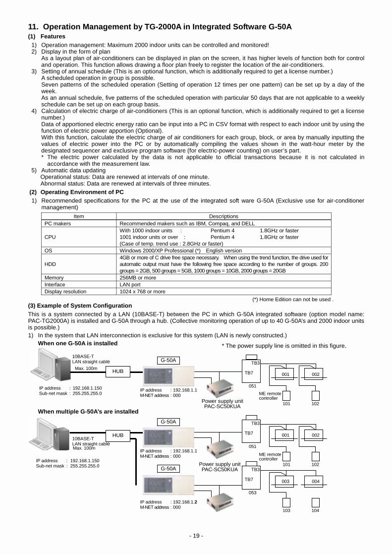
11. Operation Management by TG-2000A in Integrated Software G-50A (1) Features
1) Operation management: Maximum 2000 indoor units can be controlled and monitored! 2) Display in the form of plan As a layout plan of air-conditioners can be displayed in plan on the screen, it has higher levels of function both for control
and operation. This function allows drawing a floor plan freely to register the location of the air-conditioners. 3) Setting of annual schedule (This is an optional function, which is additionally required to get a license number.) A scheduled operation in group is possible. Seven patterns of the scheduled operation (Setting of operation 12 times per one pattern) can be set up by a day of the
week. As an annual schedule, five patterns of the scheduled operation with particular 50 days that are not applicable to a weekly
schedule can be set up on each group basis. 4) Calculation of electric charge of air-conditioners (This is an optional function, which is additionally required to get a license
number.) Data of apportioned electric energy ratio can be input into a PC in CSV format with respect to each indoor unit by using the
function of electric power apportion (Optional). With this function, calculate the electric charge of air conditioners for each group, block, or area by manually inputting the
values of electric power into the PC or by automatically compiling the values shown in the watt-hour meter by the designated sequencer and exclusive program software (for electric-power counting) on user’s part. * The electric power calculated by the data is not applicable to official transactions because it is not calculated in
accordance with the measurement law. 5) Automatic data updating Operational status: Data are renewed at intervals of one minute. Abnormal status: Data are renewed at intervals of three minutes.
(2) Operating Environment of PC 1) Recommended specifications for the PC at the use of the integrated soft ware G-50A (Exclusive use for air-conditioner
management) Item Descriptions
PC makers Recommended makers such as IBM, Compaq, and DELL CPU
With 1000 indoor units : Pentium 4 1.8GHz or faster 1001 indoor units or over : Pentium 4 1.8GHz or faster (Case of temp. trend use : 2.8GHz or faster)
OS Windows 2000/XP Professional (*) English version HDD
4GB or more of C drive free space necessary. When using the trend function, the drive used for automatic output must have the following free space according to the number of groups. 200 groups = 2GB, 500 groups = 5GB, 1000 groups = 10GB, 2000 groups = 20GB
Memory 256MB or more Interface LAN port Display resolution 1024 x 768 or more
(*) Home Edition can not be used . (3) Example of System Configuration This is a system connected by a LAN (10BASE-T) between the PC in which G-50A integrated software (option model name: PAC-TG2000A) is installed and G-50A through a hub. (Collective monitoring operation of up to 40 G-50A’s and 2000 indoor units is possible.) 1) In the system that LAN interconnection is exclusive for this system (LAN is newly constructed.)
When one G-50A is installed
When multiple G-50A’s are installed
HUB
G-50A10BASE-T LAN straight cable
IP address : 192.168.1.150 Sub-net mask : 255.255.255.0
IP address : 192.168.1.1 M-NET address : 000
Max. 100m TB3
TB7
051
001 002
ME remote controller
101 102 Power supply unitPAC-SC50KUA
10BASE-T LAN straight cable
IP address : 192.168.1.150 Sub-net mask : 255.255.255.0
IP address : 192.168.1.1 M-NET address : 000
Max. 100m
TB3
TB7
051
001 002
ME remote controller
101 102 Power supply unitPAC-SC50KUA
IP address : 192.168.1.2 M-NET address : 000
103 104
G-50A
G-50A
HUB
* The power supply line is omitted in this figure.
TB3
TB7
053
003 004

- 20 -
(4) Screen example of G-50A integrated software TG-2000A 1) Icon 2) Whole screen
3) Block screen
Operation status
Air conditioner operating Air conditioner stopping Ventilation operating Ventilation stopping
Both air conditioner/ Air conditioner operating/ Air conditioner stopping/ Both air conditioner/ interlocked equipment operating interlocked equipment stopping interlocked equipment operating interlocked equipment stopping
Abnormal status
Malfunction air conditioner Malfunction ventilation Malfunction G-50A Malfunction outdoor unit
Other status
Local remote controller Schedule being set Filter sign Operation prohibited operation prohibited
Heating
(Green): Operating (Dark gray): Stopping (Blue): Only interlocked ventilation unit operating (Yellow): Malfunction occurred
G-50A

- 21 -
4) Floor screen
5) Plan 6) Operation control screen
Menu bar
Function selection button
System status display
Displays the normal orabnormal status ofG-50A, other units
Screen display button
Floor change button Unit icon
Status bar

- 22 -
7) Abnormality monitoring
8) Air-conditioning energy charging screen (Electric power manual input)
9) Operation time When the license of Air-conditioning energy calculation function in the optional function is registered, the integrated
operation. time in grouped units can also be displayed.

- 23 -
10) Air-conditioning energy charging (electric energy pulse counting) screen • Charge screen image [Displays air conditioning charge per charge block] * Without prior notice, the content may be changed as it is under developing.
• Charge screen image [Display per watt-hour meter] * Without prior notice, the content may be changed as it is under developing.

- 24 -
(5) Limitations on group setting Item Descriptions Remarks The number of connections to the remote control
Up to 2 remote controls in one group
Except for the M-NET type remote control, registration and setting not required. *1
The number of indoor units in one group
1 to 16 indoor units
Indoor units, A-control units, K-control units, and Lossnay can’t belong to the same group. Group setting cutting across the G-50A is not possible. *2
The number of SCs and RCs in one group Up to 4 in one group * The number of the G-50A is not included.
The number of groups in one floor Up to 50 groups in one floor * Display of up to 50 groups in one floor on the whole building screen
*1: ME-remote control and MA- remote control are not allowed to be used together in one group. *2: Set up units with the same function in a group. [Symbol] SC: System controller RC: Local remote control (6) Block setting
* There are two kinds of blocks: block for operation and block for charging * The block for operation is a bunch of groups and other model groups can also be set up in the same block for operation. * The block for charging is composed of a bunch of block for operation.
(7) Function of Air-conditioning energy charging
1) In the case that there is a group not being set as a block for charging, electric power in the group is not reflected on air-conditioning charge. Set up both the block for operation and block for charging for the groups which Air-conditioning energy charging is necessary.
2) The Air-conditioning energy charging is calculated in a unit of blocks. Even if LOSSNAY with the humidifier, Free plan LOSSNAY, A-control equipment, and K-control equipment are included in the block for accounting, they are not taken into account in the ratio calculation.
3) The Air-conditioning energy charging (Electric power input by hand) is not subject to Lossnay with the humidifier, Free plan Lossnay, A-control equipment, and K-control equipment.
4) For indoor units with M-NET control system a part of the old models are not provided for the function of electric power-apportioned charging.
(8) Instructions for the use of the Air-conditioning energy charging
The air conditioning cost calculation method use by this integrated centralized control software TG-2000A is the Mitsubishi proprietary general electric power apportioning method. Depending on each country’s laws and regulations, etc., there may be cases these measured charges cannot be used for certificate of transaction. Before starting use, the building owner and building tenant should bind an agreement or contract indicating that the air conditioning charge are part of the usage fees with an independent contract indicating “The air conditioning charge are collected with an apportioning method that considers the air conditioner’s operation state instead of charges according to the measured power rate (including during emergency operation when a failure occurs)”.
(9) How to deal with the Air-conditioning energy charging at the time of failures in the PC
The power rate for air-conditioning found by means of the function of the Air-conditioning energy charging is based on the data of the operation amount of the indoor units. In the case that the data fail to be collected due to some kind or another reason, irregular treatment is to be employed. The irregular treatment may require "the maintenance of the charging data", depending on the description of the irregular treatment. Prospective failures are shown in the following table.
Group
Block for operation
Block for charging

- 25 -
1) Assumed cases and recovery method (For without WHM connection proportionally divided power charge (manual input of the electric amount))
Assumed case Air conditioning energy monitoring screen Charging data status Correction method
PC failure (HDD failure) (Display impossible) Charging data destroyed Operation amount data monitor +
remedial apportioning *1 PC failure Red characters (abnormal) G-50A communication error Black characters (normal)
Forwarded to next day and apportioned to recovery day (Collected for several days and apportioned)
No repair is required *2
G50A main unit failure Black characters (normal) Apportioned, but data is not correct (Interval : Error day ~ recovery data) Charging data maintenance
System information setting error Black characters (normal) Apportioned based on set information Charging data maintenance
*1 To repair, the operation amount during the time to be repaired is monitored, and the remedial apportioning function is used. *2 When a forwarding that extends past the settlement-of-accounts day occurs, it is recommended to correct it in the "Charge data
maintenance" screen. It is unnecessary to perform this procedure when there is an agreement that allows the charge to be collected, even if the forwarded settlement occurs.
Note : • If there are two or more assumed cases, make overall judgment. • When forwarding of apportionment spans the settlement-of-accounts day, the forwarded portion is added to the next month. When you
want to separate this month's portion and next month's portion, divide the proportion division parameter forwarded and collected by "Charge data maintenance" screen by the number of days in next month and this month.
• The charge data status is irregularly processed according to the case which occurred.
2) Outline of the maintenance of charging data (Refer to ‘The maintenance of the charging data’ in the instruction manual of
the integrated software TG-2000A for details.) Outline The maintenance of charging data
Change and correct the parameterized data for apportion to be corrected for each indoor unit and for each day. After completing the data correction perform the Air-conditioning energy charging again to figure out power rate for air conditioning.
12. Basic Set-up Procedures for Integrated Software TG-2000A * Refer to the instruction manual of Integrated Software TG-2000A for details. Step 1 : Confirmation of PC environment Check if settings of OS environment, IP address, time, etc. are completed. Step 2 : Set-up - Carry out the Step 1 ・・・・・・・・・・・・・・・・・・・・ Set-up of MSDE * Be sure to restart the PC after the completion of the set-up. Step 3 : Set-up - Carry out the Step 2 ・・・・・・・・・・・・・・・・・・・ Set-up of database Step 4 : Set-up - Carry out the Step 3 ・・・・・・・・・・・・・・・・・・・・ Set-up of the main body * Be sure to restart the PC after the completion of the set-up. Step 5 : Initial setting - User setting Make a choice of functions to be used. Step 6 : Initial setting - Setting of building name Step 7 : Initial setting - Setting of G-50A connection Check if settings of the number of G-50A, IP address, optional function, etc. are completed. Step 8 : Initial setting - setting of system configuration Check the system configuration by the data from G-50A * The data from G-50A is collected once at the time of start only because of the first setting. Step 9 : Initial setting - Setting of display for monitoring Settings of model name, floor plan, icon allocation, etc. Step 10 : Initial setting - Setting of charging system Settings of parameter for indoor unit, charging block, power rate, etc. Step 11 : Initial setting - Setting of information Complete the settings and send set-up information to G-50A.

- 26 -
13. Calculation of Air Conditioning Energy Charging (Manual input, pulse count method) (1) System composing equipment and software By the optional integrated software and its license registration to the G-50A unit, the air conditioning charge of the Multi air conditioners can be calculated based on the operation record. Depending on the collecting method (3 methods below) of information on watt-hour meter, the system composition, peripheral components and contents differ.
Major equipment required Function Air-conditioning energy charging Electricity information collecting method Hardware Software Manual input (Simplified air con. electricity charge)
G-50A, PC, LAN (Ethernet), HUB
Integrated software TG-2000A (Option) Charge license, web monitor license No. (*)
Pulse count
G-50A, PC, WHM with pulse oscillator, Sequencer (MELSEC-Q) and others, LAN (Ethernet), HUB
Integrated software TG-2000A (Option) Electricity counting software Charge license, web monitor license No. (*)
Air-conditioning energy charging * During the use of this
function, the time setting can not be ap-plied to the G-50A unit.
Direct intake (Electricity data) to PC (RS485)
G-50A, PC, RS485WHM, LAN (Ethernet), HUB, RS232C / RS485 converter
Integrated software TG-2000A (Option) Charge license, web monitor license No. (*)
* When the charging is used, all G-50A’s being controlled will be the object, and the license for Air-conditioning energy charging is required for all G-50A’s. Even when charging a part of the G-50A’s, the license is still required for all G-50A’s.
(2) Air conditioners to be controlled by G-50A
Type (the series name)
Air-conditioning energy charging (Electric power manual input)
without watt-hour meter (WHM)
Air-conditioning energy charging (Electric power pulse count)
with watt-hour meter (WHM) or RS485WHM City Multi Y Series (8~20HP) City Multi Super Y Series (24~30HP) City Multi R2 Series (8~20HP) City Multi WR2 Series (8, 10HP) City Multi WY Series (8, 10HP)
(Pump and cooling tower power supply can not have apportioned charge.)
(Pump and cooling tower power supply can not have apportioned charge.)
City Multi S Series Mr. Slim Series (A-control) x (Each billing unit needs a watt hour meter installed.)Split Type Air Conditioner (A-control) x (Each billing unit needs a watt hour meter installed.)K-Control Series x (Each billing unit needs a watt hour meter installed.)Lossnay (GUF Series : OA processing Units) x (Incase it’s set as an indoor unit) Lossnay (LGH Series) x (Each billing unit needs a watt hour meter installed.)
*1 Pump and cooling tower power supply cannot have apportioned charge. However, a watt-hour meter may be mounted to each billing unit for solution.
(3) PC operating environment
Item Content PC PC/AT convertible model PC maker Recommended (IBM, Hp Compaq, DELL) CPU Pentium 4 1.8GHz or more OS Windows 2000/XP Professional (*1) English version HDD C-drive capacity 4GB or more Memory 256MByte or more LAN LAN port Serial port Requires serial port when using the WHM of RS485 communication Display resolution 1024 x 768 or more
Caution :
(1) Windows 2000/XP Home Edition can not be used. (2) Recommend using uninterrupted power source for PC as the data will be collected daily. (3) Please do not shut down Windows within the time frame collecting the charge data.
The time frame allowing the shutdown is 08:00 - 21:45. (The charging information will be collected during a time frame from the midnight to around 07:15.)

- 27 -
(4) System configuration and scheme of the Air-conditioning energy charging (Power rate manually input) Power rate for air-conditioning is calculated by inputting the data from the watt-hour meter of the indoor units and outdoor units by the use of the Air-conditioning energy charging tool in the integrated software. * Setting of a basic rate by the use of the tool is not possible.
1) IP addresses of G-50A and PC Setting methods for address IP addresses
IP address 192.168.1.1 ~ 192.168.1.40 G-50A Sub net mask
Set up by G-50A main body or initial setting tool 255.255.255.0
IP address 192.168.1.150 (192.168.1.101 ~ 192.168.1.150)
PC TG-2000A
Sub net mask
Property of the Internet protocol of the control panel
255.255.255.0
2) Restrictions on wiring • Between G-50A and Hub : LAN 10BASE-T Allowable maximum length 100m In case that the length of 10BASE-T wiring exceeds 100m, refer to "Restrictions on LAN" on another page. • Between power supply unit and G-50A : Allowable maximum length 200m Kind of wiring : Shielded wire CVVS, CPEVS, and 2-core cable with 1.25mm2 or more Example) At the time of wiring a new LAN 3) Scheme of power rate calculation a) Basic rate The Air-conditioning energy charging (electric power manually input) is provided only with the function of calculating
power rate for air-conditioning with operation data and is not ready for basic rate-setting function. It is necessary for users to add a basic rate to the power rate.
b) Electric charge of air-conditioner The electric charge ratios of the indoor units and outdoor units are separately calculated. With the data manually input
of the difference in consumed electric energy of the indoor units and outdoor units between previous month and this month, power rate for air-conditioning is calculated in each block (tenant) by the use of Excel tool and the like.
c) Each apportion parameter of the outdoor unit The parameter of each indoor unit and each power rate is respectively calculated with the rated capacity of the indoor
unit. Then the ratio with the sum of the total blocks is figured out by summing up the values multiplied the unit rate of the number of blocks.
Apportion parameter = Integrated value of capacity control level (capacity saving ratio and thermostat working hours) x Rated capacity of indoor unit
Power rate parameter = ∑ (Apportioning parameter x Unit rate)
Apportion parameter (ratio %) = d) Each electric power apportion parameter of indoor unit The parameter of each indoor unit and each power rate is separately calculated with the power consumption of the
indoor units and the rated power of the auxiliary heater. Then the ratio with the sum of the total blocks is figured out by summing up the values multiplied the unit rate of the number of blocks.
Apportion parameter = Running hours of the indoor unit fan x Rated power consumption (+ working hours of the auxiliary heater x Power for auxiliary heater) ∗ Power rate parameter = ∑ (Apportioning parameter x Unit rate)
Apportion parameter (ratio %) = ∗ In case of no auxiliary heater value of ( ) is 0.
HUB
G-50A
Power supply unit
PAC-SC50KUA
10BASE-T LAN straight cable
IP address : 192.168.1.150 Sub-net mask : 255.255.255.0
IP address : 192.168.1.1 M-NET address : 000
Max. 100m
Max. 100m
TB3
TB7
051
001 002
G-50A
IP address: 192.168.1.2 M-NET address: 000
TB3
TB7
053
TB3
TB7
055
003 004
005 006
103 104
105 106
ON/OFF remotecontroller
203
101 102
Total power rate parameters of relevant blocksTotal power rate parameters of total blocks
Total power rate parameters of relevant blocksTotal power rate parameters of total blocks
Power supply unit
PAC-SC50KUA

- 28 -
(5) System configuration and scheme of the Air-conditioning energy charging (Power rate pulse-count) 1) IP addresses of G-50A and PC
Setting methods for address IP addresses IP address 192.168.1.1 ~ 192.168.1.20 G-50A Sub net mask
Set up by G-50A main body or initial setting tool 255.255.255.0
IP address 192.168.1.151 ~ 155 Sequencer MELSEC-G Sub net mask
Set up at the time of delivery by electric energy counting software or responding to orders 255.255.255.0
IP address 192.168.1.150 (192.168.1.101 ~ 192.168.1.150)
PC
Sub net mask
Property of the Internet protocol of the control panel
255.255.255.0
* The integrated software is required to register the IP address of the sequencer (MELSEC-Q) * Up to 5 sequencers are allowed to be connected in one system. 2) Restrictions on wiring • Between G-50A and Hub : LAN 10BASE-T Allowable maximum length 100m In case that the length of 10BASE-T wiring exceeds 100m, refer to "Restrictions on LAN" on page 36. • Between power supply unit and G-50A : Allowable maximum length 200m Kind of wiring : Shielded wire CVVS, CPEVS, and 2-core cable with 1.25mm2 or more • Between watt-hour meter and sequencer (MELSEC-Q) : Allowable maximum length 150m (maximum) Kind of wiring: CPECV-S cable φ 0.9 or more, or CVVS 1.25mm2 or more 3) Watt-hour meter • As to the watt-hour meter with pulse oscillator, select recommended models or other watt-hour meters complying with
requirements set in the specifications below. • In the case of Building Multi, install watt-hour meters separately to the indoor unit system and outdoor unit system. • As up to 5 sets of the sequencer can be set to 1 system, install 160 sets maximum. Specifications: Specification of the contact point of watt-hour meter with pulse oscillator • Output pulse : Semiconductor relay system, Pulse width : 100 to 300m sec Example) At the time of wiring a new LAN
* Refer to " WHM Wiring System Example" on another page 30 for details.
G-50A
HUB
G-50A10BASE-T LAN straight cable
IP address : 192.168.1.150 Sub-net mask : 255.255.255.0
IP address : 192.168.1.1M-NET address : 000
IP address : 192.168.1.2M-NET address : 000
Max. 100m
TB3
TB7
051
TB3
TB7
053
001 002
003 004
101 102
103 104
Sequencer (MELSEC-Q)(1) Power supply unit
(Q61P-A1(A2)) (2) CPU (Q02CPU) (3) Ethernet (QJ71E71-100) (4) DC input (QX40) (5) Electric energy counting
software
IP address: 192.168.1.151
Insulating transformer
DC power source, breaker
Up to 16 watt-hour meters can be connected to one DC input (QX40).
Arrestor
Watt-hour meter with
pulse oscillator
CPECV-s cable φ 0.9 or more, or CVVS 1.25mm2 or more Max. extension: up to 150m
Watt-hour meter with
pulse oscillator
•••
Power supply unit
PAC-SC50KUA
Power supply unit
PAC-SC50KUA

- 29 -
4) Set-up of power rate for air-conditioning a) Basic rate Of all power contract rates covering the whole building, a contract rate related to air-conditioning systems by each block
(tenant) is respectively set up. The basic rate is constant every month. b) Electric charge of air-conditioner This is a rate being figured out based on the apportioned calculation of actually consumed electric power by block. Both
settling day calculation and maturity-designated time calculation are available. * Settling day calculation: Electric charge of air-conditioner for a period of one month counting from a registered settling day is calculated. The
rate is made up and figured out between around 4:00 and 8:00 on the following day of the settling day. (While making up the rate, the PC may become slow to response.) * Maturity-designated time calculation: Electric charge of air-conditioner for a desirable arbitrary period for 61 days counting from the previous day is
calculated. c) Electric charge of air-conditioner by time frame Electric charge of air-conditioner for a period of one day is calculated apportioned by two time frames (*). Time frame
section can be set up by a day of the week. Also, 5 patterns of time frame section in a year can be set up to 50 days. The time frame divided in 5 sections is under development (Refer to the development separately)
Use example: In the case that power rate for air-conditioning loaded between 9:00 and 18:00 is collected together with tenant fee, and that of air-conditioner used between 18:00 and 9:00 in the following morning during overtime duties is desired to be collected according as the use situation, do as follows. Split the time frame into two parts of "9:00 to 18:00" and "18:00 to 9:00 in the following morning, set up a price of zero as a rate for the former and a power unit rate for 18:00 to 9:00 "in the following morning for the latter.
d) Seasonal rate The rate can be set to the summer seasonal rate and normal rate separately.
e) Weekly rate Setting up power unit rate by a day of the week is also possible. 5) Scheme of power rate calculation a) Power rate for air-conditioning (settle up) (A) Basic rate + (B) electric charge of air conditioner (A) Basic rate : Set up and registered basic rate by billing block (tenant) to be charged (B) Electric charge of air conditioner : It is figured out by making an apportioned calculation of electric energy
consumed for air conditioning according to the running status of the air-conditioners, and then by multiplying a unit rate by electric energy after finding the electric energy consumed by each tenant.
Apportioned calculation of electric power used by indoor unit Rated power consumption of indoor unit x Accumulated working hours of fan Electric energy used by the indoor unit is found based on the electric energy measured by the watt-hour meter with the sum
of the above electric energy (parameter value) and its proportion.
Apportioned calculation of electric power used by outdoor unit Electric power used by the indoor unit is divided into standby electric power and other electric power. Standby electric power * → Apportioned calculation by the proportion of indoor unit capacity Other electric power → Indoor unit capacity x Proportional division by the proportion of capacity control level Electric power used by the outdoor unit is found based on the electric power measured by the watt-hour meter with the sum of the above electric power (parameter value) and its proportion.
* The standby electric power can be selected from the following three kinds of calculation methods. (1) Apportioned calculation by the proportion of indoor unit capacity in the same refrigerant system (2) Without apportion calculation by electric power as outdoor unit standby electric power (3) Without taking standby electric power into account (0), apportioned calculation by other electric power only
The electric power is calculated in a unit of blocks. Even if Lossnay, A-control model, and K-control model are included in the system, electric power for each of these models is not calculated respectively, and it is figured out by a proportional ratio of M-control model.

- 30 -
System Example of Watt Hour Meter (WHM) - PLC under of Air-Conditioning Energy Charging (Power Pulse Count)
Installation side of Air conditioner/WHM Local control panel
When centralized controller G-50A exceeds 4 sets, use HUB with 8 branches or more.
To Air conditioning control PC <Integrated software : TG-2000A>
To air conditioner <M-NET centralized system>
To air conditioner <M-NET centralized system>
<Rooftop> Power panel/ distribution board, etc.
Pulse output
terminal
Pulse output
terminal
Pulse output
terminal
Pulse output
terminal
WHM 1 (Pulse output)
WHM 2 (Pulse output)
WHM 15 (Pulse output)
WHM 16 (Pulse output)
Max. extended distance : 150m
Recommended cable CPEV-S cable φ 0.9 or more, or CVVS 1.25m2 or more
* When mounting G-50A of 3 sets or more into the panel, follow the diagram below for reference.
LAN (10BASE-T)
LAN (10BASE-T)
M-NET transmission line
LAN (10BASE-T)
G-50A
G-50A
M-NET transmission line
Arrestor for pulse input (Lightning arrestor)
Arrestor
Arrestor 2
Arrestor 15
Arrestor 16
Note 1. For the power source and input wiring of PLC,take the provision of grounding and lightningsurge into account.
Note 2. For the external wiring, be sure to use shieldedwire and apply grounding work (except for LAN wiring).
AC adapter
CN (Plug socket)
Power supply unit PAC-SC50KUA Mitsubishi Electric made External dimension:
W265 x H240 x D59.2
M-NET Power supply device
Power source
MCCB 1 MCCB 0
Centralized controllerG-50A External dimension : W300 x H120 x D79 M-NET Power
supply device
M-NET Power supply device
MCCB 2
MCCB 3
DC24V output
Power source
Power source
MCCB 4
Insulatingtransformer
DC power source device
PLC
Power source unit (Q61P-A1(A2))
CPU unit (Q02CPU)
Ethernet interface unit (QJ71E71-100) 10BASE-T connector DC input unit (QX40<16 points>)
COM NC XCF XDF X01 X00
Insulating transformer
PLC (Sequencer) Q Series : Mitsubishi Electric made External dimension : W189 x H98 x D44.1
Arrestor for power source <Lightning arrestor>
WHM (Pulse Input) and PLC Connection System Example (Same Installation of G-50A and PLC)
Main power source breaker
Supply power source AC100V or AC200V
Power source
Earth

- 31 -
14. System Design Flow and Test Run of Air-Conditioning Energy Charging (1) System design flow of Air-conditioning energy charging (∗ RS-485WHM system is not included)
Step 1 Selection of air conditioning equipment (Model, refrigerant system, installation location) Step 2 Type, number and pulse multiplying factor of the watt-hour meter Step 3 Confirmation of data input method of electric energy (Confirmation of manual input or automatic counting) Method 1 Manual data input method of electric Method 2 Automatic counting method of energy data electric energy Step 4 Sequencer for electric energy counting Determination of the number of (MELSEC-Q)
Step 5 System classification Step 6 Determination of installation location and the number of G-50A, power supply unit, and PC for management Step 7 Determination of the address of air-conditioning equipment, PC, etc Step 8 Confirmation of administration (contents of setting) of air-conditioning charge * Refer to "Check sheet of information on system registration of electric power-apportioned charging" on another page. Step 9 Confirmation of other items and optional functions
(2) Procedures for test run of electric power-apportioned charging * Refer to the section "Test run check" in the integrated software TG-2000A (Field adjustment edition). 1) Rough test run of electric power-apportioned charging is as follows: The first day (1) Confirmation of the setting contents of man/machine The second day (2) First confirmation of meter values of the watt-hour meter (3) Running operation of air-conditioning equipment (2 hours or more) (4) Second confirmation of the meter values of the watt-hour meter The third day (5) Confirmation of the results of apportioned charging (6) Confirmation of the results of settlement (7) Criterion
Conduct the operation for over 2 hours. It takes three days after registration of setting to confirm the data. ∗ Please refer TG-2000A Operation Manual (Site adjustment) for method of test run of air-conditioning energy charging.

- 32 -
2) Test run procedure and tool
Composition 1 Composition 2 Composition 3 Composition 4
Single G-50A PC without remote
Web browser PC control/monitor
Integrated control software, PC control/monitor
With simplified power apportioned charging
Composition 2, 3 + Remote monitor
With mail transmission
Function of tool setting/confirmation
Tool Tool Tool Tool Tool
No.
Test run item
Content of work
Necessity
of work G-50A unit
Initial setting
tool
Necessity
of work G-50A unit
Initial setting
tool
Web browser
Necessity
of work G-50Aunit
Initial setting
tool
Web browser
TG- 2000A
Necessity
of work Initial
setting tool
Router setting
PC
G-50A unit
Initial setting
tool
Web browser
TG- 2000A
Router setting
PC
- Test run of air
conditioner unit
M-NET address
IP address
Time setting ( )
License registration of optional function
Selection of external input/output function
1 Setting of G-50A
unit
Network setting
Installation of integrated control software
2 Setting of
controlling/
monitoring PC
Group setting
Ventilation interlocked setting
Control block setting
3 Setting of
group/block
Floor setting
Plan drawing
4 Preparation of
plan
Registration of charge information
Setting of charge block
5 Charge setting
Weekly schedule setting
Annual schedule setting
6 Schedule setting
Confirmation of control result/display content of air conditioners 7 Confirmation of
operation
Confirmation of meter value Confirm the WHM indicated value visually. Confirm the WHM indicated value visually
Confirmation of calculation adjustment
Correction of data
8 Confirmation of
charged result
Setting of dialup router
Setting of network
Setting of mail address/recipient
Setting of abnormal mail transmission
9 Setting of remote
monitoring
: Required : Able to set or confirm : Can be set only with the specified tool
Can be registeredonly through the browser !
Requires the in- tegrated software when provided with charging function!

- 33 -
15. Check Sheet of Information on System Registration of Air Conditioning Energy Charging (1) Information on setting of power rate
1) Confirmation of the pro and con of midnight rate and/or midnight electric power setting
In specified hours/out of specified hours, Not specified In specified hours/out of specified hours, Specified
2) Power unit rate
In specified hours Out of specified hours
3) Range of "In specified hours" (Time registration)
Range of "In specified hours" hour minute ~ hour minute
4) Confirmation of the pro and con of week end rate setting
Week end specified Friday Saturday Sunday
5) Week end piece power rate when specified
In specified hours Out of specified hours
6) Range of "In specified hours" when specified (Time setting)
Range of "In specified hours" hour minute ~ hour minute
7) Period setting of seasonal rate setting
Day month ~ Day month
8) Seasonal rate setting of the range of "In specified hours" or "Out of specified hours"
In specified hours Out of specified hours
9) Range of "In specified hours" of seasonal rate setting (Time setting)
Range of "In specified hours" hour minute ~ hour minute
10) Confirmation of the pro and con of weekend rate setting in the period of seasonal rate
Weekend specified Friday Saturday Sunday
11) Week end unit rate in the period of seasonal rate
In specified hours Out of specified hours
12) Range of "In specified hours" when weekend rate in the period of seasonal rare is specified (Time setting)
Range of "In specified hours" hour minute ~ hour minute
(2) Setting of settling day Settling day for air-conditioning fee
At the end of month Day specified

- 34 -
16. Outline of Energy Saving Control * The specification may be changed as this system is under development. (1) Energy saving control The energy saving control includes the items listed on Table 9-2, and they can be set from the integrated software for each
block freely. After setting, G-50A conducts energy saving control on to the air conditioning group within the operation block in a unit of 3
(3/6/9/15/30 minutes) within a 30 minutes not allowing overlapping1 the control time. In consideration of comfort, it can be set not to apply the set energy saving control2 to the block of which temperature
difference between the set and inlet temperature exceeds the temperature difference freely set (3°C ~ 9°C). (Setting of inffective energy saving control by temperature difference)
Control unit Control items Control detail Set temperature control
Cool/dry : +2°C, Heat : −2°C (No control for fan, auto) • Shifting by ±2°C at control start time, returning to original temperature at control finish. • When set temperature was changed from local remote controller, browser, G-50A unit or schedule
during temperature control, and the temperature value at control finish differed from that at the start, it does not return to the state before the control.
Fan (thermostat OFF) control
Capacity saving 0% control for Free Plan indoor units and A-control Slim indoor units. Fan operation control for the models before Free Plan. • When the mode was changed from remote controller, browser, G-50A unit or schedule during fan
mode control, and the mode at control finish was that other than fan mode, it does not return to the sate before the control.
Indoor unit
Stopping control
Stopping outdoor unit • Transmits "STOP" at control start time and returns to the original start/stop state at control finish.• When the operation was made from local remote controller, browser, G-50A unit or schedule
during stopping control, and the state at control finish was not stopping, it does not return to the sate before the control.
Outdoor unit Capacity saving control 3
The maximum value of outdoor unit operating capacity can be controlled to 60%/70%/80% /90% (in 10% unit).
1 The control time may be overlapped depending on the group numbers inside block and control time. 2 Energy saving control is applied at the levels 1~4 regardless of the temperature difference. 3 Controllable only for City Multi air conditioners. (Do not set to Multi-S.)
(2) Peak cut control Connecting the watt-hour meter (PLC) allows conducting the energy saving control of Table 9-2 divided into 5 levels (Level
0 ~ Level 4) by estimating the power consumption for 30 minutes. Meantime, the control level is judged with an interval of 1 minute, and the control of higher level is applied in accordance
with the measured power consumption for the past 30 minutes and estimated value.
(1) Times of rotation: For the control of 6 minutes, 3 minutes control is applied for 2 times (= 6 min./3 min.). (2) Cycles of rotation: From the times of rotation in (1), the cycle of rotation for 30 minutes is to be 15 minutes (= 30 min./2 times) (3) Intervals of rotation: From the cycles of rotation in (2), the rotation interval of each group in a block counts for 3 minutes (= 15 min./5 groups). (If
indivisible, round it to the nearest whole number.)
0 3 6 9 12 15 18 21 24 27 30 (min.)
Group 1
Group 2
Group 3
Group 4
Group 5
[In case of the energy saving control of indoor unit for 6 minutes when 5 groups are in one block for example]

- 35 -
How to obtain the estimated value : Estimated value (kW) = Power consumption in the past 5 minutes (kWh) x 6 (Power consumption for 30 minutes) x 2 (kWh→kW <30 minutes> converted) . . . . . . (1) In Figure 9-5 for example, it is assumed that the control at the energy saving Level 1 is being conducted in accordance with [Power consumption for the past 30 minutes]. In this occasion, the estimated value after 30 minutes is calculated from [Power consumption for the past 5 minutes] by Equation (1), it reaches the region of energy saving Level 2. In this case, the energy saving control set at the energy saving control Level 2 will be carried out. By making the energy saving ineffective temperature difference effective, under the control of Level 0, when the temperature difference between the set and inlet temperature is exceeding 3°C ~ 9°C (able to set in a unit of 1°C), it is possible not to allow conducting the energy saving control set at Level 0 in consideration of comfort. (The control set at Level 1 ~ Level 4 will be conducted regardless of the temperature difference.)
By setting the target demand value and [Stopping control for 30 minutes] of the energy saving control item, the peak cut control can be practiced as an application of the level control above. (3) Example of effectiveness by energy saving control
Energy saving control effect
Delivered to a certain electric manufacturer : 1F Production line, 2F Design department Air conditioner models delivered 1F : 4 sets of Building use Multi Air Conditioner, 5 sets of system use air conditioner 2F : 74 sets of Building use Multi Air Conditioner, 11 sets of System use air conditioner Installation 1F : 1 set. 2F : 2 sets Operation start: From August 2001
Outline of energy saving control 1F Production line : Switching [COOL] to [FAN] for 3 minutes once a 30 minutes 2F Design floor : Switching [COOL] to [FAN] for 3 minutes once a 15 minutes Setting the set temperature of cooling higher than 2°C for 3 minutes once a 30 minutes Whole floors : Stopping at 22:00 once to prevent neglecting the machine shutdown
(1) Energy saving effect by time frame (Quoted from Power consumption daily report)
To verify the energy saving effect at the 2F design floor southside, the control operation and ordinary operation wereconducted for comparison. [Result] Verified 13% ~ 17% saving effect • Verification of energy saving control:
Power consumption at 2F design floor south side (July 2001)
(2) Power consumption record of whole building After August 2001 when this control was introduced, the powerconsumption reduced by 10 ~ 23% comparing to that in the previousyear thus proving an energy saving effect.
Without energy saving control Switching of fan mode (for 6 minutes)
12:00 13:00 14:00 15:00 (Time)
Pow
er c
onsu
mpt
ion
(kW
h)
186 154
184 160
Aug., 2001 Control Started
May June July Aug. Sept.
Pow
er c
onsu
mpt
ion
(kW
h)
Year 00 Year 01
Reduced by 13% ~ 17%
Reduced by 10% ~ 23%
30,6
14
36
,533
63,9
71
63,8
83
94,2
61
101
,642
92,7
66
83,
645
68,6
46
52,7
02
3kWh 2kWh 1kWh
10kWh
Power consumptionfor past 5 minutes
Power consumptionfor past 30 minutes Estimated power
consumption after 30 minutesLevel 2
Level 1
120kW
Estimated power consumption for 30 minutes
120kWEstimation of mean electric power for 30 minutes (demand value)
Before 5 minutes Present 30 minutesLevel estimation

- 36 -
17. Restrictions on wiring for LAN (1) Kind of LAN
1) Principal standards of cable a) 10BASE-5 Standard wire coaxial cable Maximum allowable length 500m b) 10BASE-2 Fine wire coaxial cable Maximum allowable length 185m c) 10BASE-T Twist pare cable (T) Maximum allowable length 100m d) 100BASE-TX Twist pare cable (T) Maximum allowable length 100m 2) Communication speed a) 10Mbps starting with 10BASE b) 100Mbps starting with 100BASE 3) EIA/TIA568 (category) In twist pare cable there is a standard for category classification established by EIA/TIA (Electronics Industry Association/
Telecommunications Industry Association) and in Ethernet, category 3 and category 5 are applied. * Category differs depending on transmission speed available. In category 5 data are transmitted 10 times faster than in
category 3. Category 1 For telephone Category 2 For telephone and Apple Talk (Transmission speed: 4Mbps) Category 3 10BASE-T and Token Ring (Transmission speed: 10Mbps) Category 4 Token Ring (Transmission speed: 16Mbps) Category 5 10BASE-T and 100BASE-T (Transmission speed: 100Mbps) For 10BASE-T there are two categories: category 3 and category 5. For 100BASE-T there is category 5 only.
4) Recommendation and instructions on G-50A a) Category 10BASE-T is recommended for cable for LAN As a system mixing with optical cable 100BASE-TX may be used, category 5 is recommended judging from availability. b) On specifications of the hub There are several kinds of hubs such as 10BASE-T, 100BASE-TX (automatic switching type), exclusive for 10BASE-T
and exclusive for 100BASE-T. In use of G-50A the hub should be selected one which 10BASE-T is available.
What is cascade connection? This is to connect between multiple ports of hub with cable in layered structure. The port can be added on. Restriction on the number of layer in cascade connection:
The increase in the layer of cascade leads delayed time to become longer, resulting in bringing the impossibility of collision detection. Therefore, the limitation on the number of layer of cascade is provided as follows: * 4 layers for 10BASE-T * 2 layers for 100BASE-TX
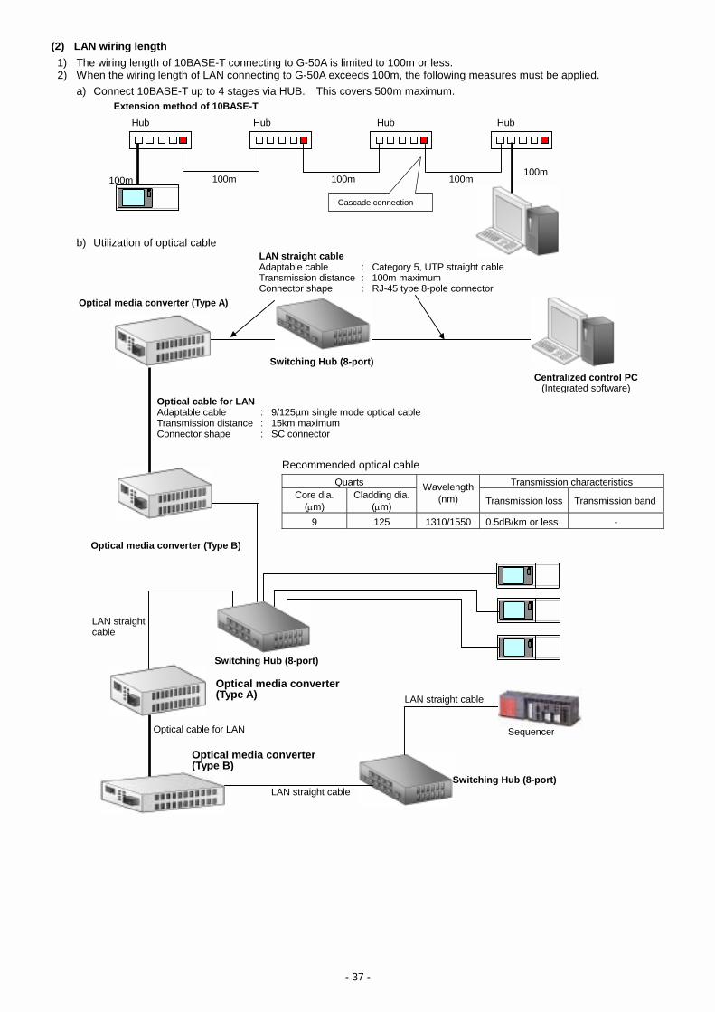
- 37 -
(2) LAN wiring length 1) The wiring length of 10BASE-T connecting to G-50A is limited to 100m or less. 2) When the wiring length of LAN connecting to G-50A exceeds 100m, the following measures must be applied. a) Connect 10BASE-T up to 4 stages via HUB. This covers 500m maximum. Extension method of 10BASE-T
b) Utilization of optical cable
Optical media converter (Type A)
Cascade connection
LAN straight cableAdaptable cable : Category 5, UTP straight cable Transmission distance : 100m maximum Connector shape : RJ-45 type 8-pole connector
Switching Hub (8-port)
Optical cable for LAN Adaptable cable : 9/125µm single mode optical cableTransmission distance : 15km maximum Connector shape : SC connector
Optical media converter (Type B)
Recommended optical cable
Quarts Transmission characteristics Core dia.
(µm) Cladding dia.
(µm)
Wavelength (nm) Transmission loss Transmission band
9 125 1310/1550 0.5dB/km or less -
Switching Hub (8-port)
Optical cable for LAN
Optical media converter (Type B)
LAN straight cable
LAN straight cableSwitching Hub (8-port)
Sequencer
Optical media converter (Type A) LAN straight cable
Hub Hub Hub Hub
100m 100m 100m 100m100m
Centralized control PC(Integrated software)

- 38 -
18. License Registration of Optional Functions When the function of annual schedule, the function of electric power-apportioned charging, and the function of energy-saving control are used, a license registration is required respectively. License registration example:
(1) Open the window for license registration of optional functions Input Web page address in the address field of Web browser and press "Enter" (return) key of the keyboard, and the window for pass- word input is opened. http://(IP address of G-50A)/administrator.html Click ‘License registration of optional functions’ in the menu of the window, and the window for license registration of optional functions is opened. (2) Register the license of optional functions Select a function desired to be license-registered from the selection field for optional functions on the window for license registration of optional functions, and the current availability is displayed. Then, input a purchased license number and click "License registration" button, and the registered optional function becomes available. When it can not be registered normally, check if the key code is wrong or if the selected function is different from the function to be register.
Input of pass wordReturn to the window for
pass word input
Current availabilityThe availability of optional
functions is displayed on the screen.
Button for license registrationRegister a license
Selection field for optional functionsSelect the kind of optional function to be license-registered. Input field for license number Input license number to be registered.
Registration of optional functions
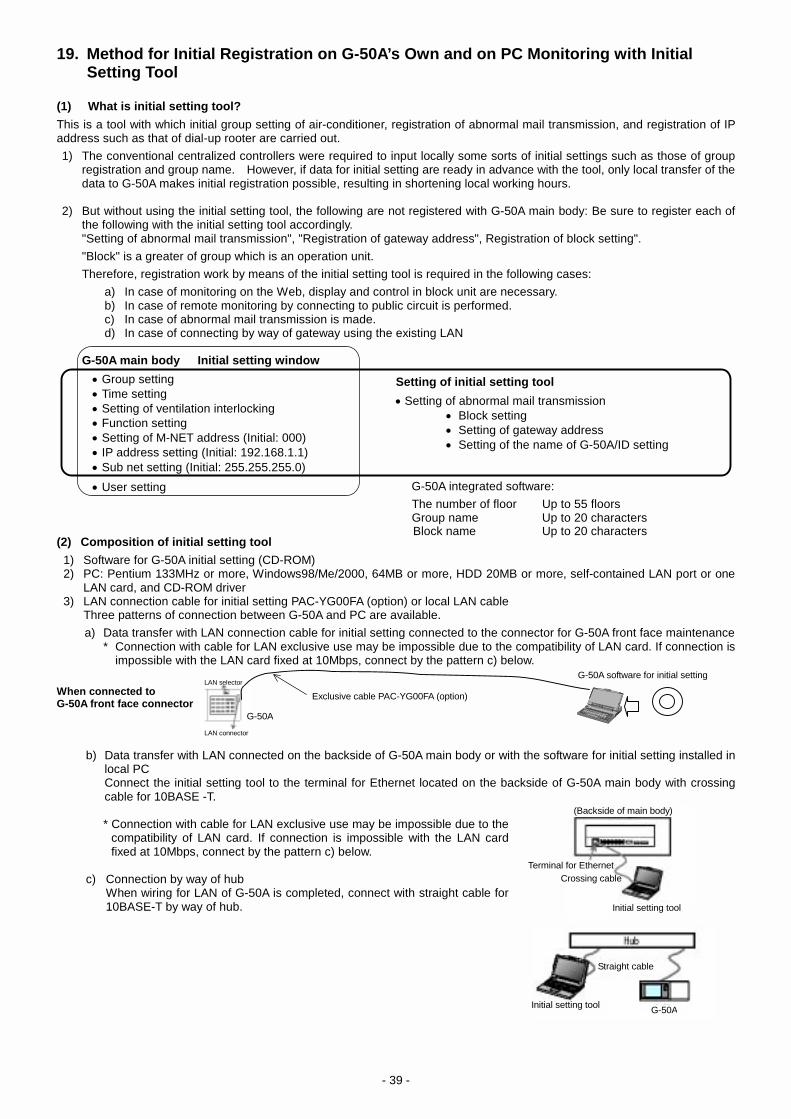
- 39 -
19. Method for Initial Registration on G-50A’s Own and on PC Monitoring with Initial Setting Tool (1) What is initial setting tool? This is a tool with which initial group setting of air-conditioner, registration of abnormal mail transmission, and registration of IP address such as that of dial-up rooter are carried out. 1) The conventional centralized controllers were required to input locally some sorts of initial settings such as those of group
registration and group name. However, if data for initial setting are ready in advance with the tool, only local transfer of the data to G-50A makes initial registration possible, resulting in shortening local working hours.
2) But without using the initial setting tool, the following are not registered with G-50A main body: Be sure to register each of
the following with the initial setting tool accordingly. "Setting of abnormal mail transmission", "Registration of gateway address", Registration of block setting". "Block" is a greater of group which is an operation unit. Therefore, registration work by means of the initial setting tool is required in the following cases:
a) In case of monitoring on the Web, display and control in block unit are necessary. b) In case of remote monitoring by connecting to public circuit is performed. c) In case of abnormal mail transmission is made. d) In case of connecting by way of gateway using the existing LAN
G-50A main body Initial setting window • Group setting • Time setting • Setting of ventilation interlocking • Function setting • Setting of M-NET address (Initial: 000) • IP address setting (Initial: 192.168.1.1) • Sub net setting (Initial: 255.255.255.0) • User setting (2) Composition of initial setting tool
1) Software for G-50A initial setting (CD-ROM) 2) PC: Pentium 133MHz or more, Windows98/Me/2000, 64MB or more, HDD 20MB or more, self-contained LAN port or one
LAN card, and CD-ROM driver 3) LAN connection cable for initial setting PAC-YG00FA (option) or local LAN cable Three patterns of connection between G-50A and PC are available.
a) Data transfer with LAN connection cable for initial setting connected to the connector for G-50A front face maintenance * Connection with cable for LAN exclusive use may be impossible due to the compatibility of LAN card. If connection is
impossible with the LAN card fixed at 10Mbps, connect by the pattern c) below.
When connected to G-50A front face connector
b) Data transfer with LAN connected on the backside of G-50A main body or with the software for initial setting installed in
local PC Connect the initial setting tool to the terminal for Ethernet located on the backside of G-50A main body with crossing cable for 10BASE -T.
* Connection with cable for LAN exclusive use may be impossible due to the
compatibility of LAN card. If connection is impossible with the LAN card fixed at 10Mbps, connect by the pattern c) below.
c) Connection by way of hub When wiring for LAN of G-50A is completed, connect with straight cable for
10BASE-T by way of hub.
Setting of initial setting tool • Setting of abnormal mail transmission • Block setting • Setting of gateway address • Setting of the name of G-50A/ID setting
G-50A integrated software: The number of floor Up to 55 floors Group name Up to 20 characters Block name Up to 20 characters
Exclusive cable PAC-YG00FA (option)
G-50A software for initial setting
LAN connector
LAN selector
Terminal for EthernetCrossing cable
Initial setting tool
G-50A
Straight cable
Initial setting tool
(Backside of main body)
G-50A

- 40 -
Table of System Management Composition
Indoor unit Outdoor unit Unit address
Point name Installed
floor Model name Serial No. Serial No. Model name Outdoor unit
address
BC controller address
Branch No.
G-50A system No.
Remarks
01 02 03 04 05 06 07 08 09 10 11 12 13 14 15 16 17 18 19 20 21 22 23 23 24 25 26 27 28 29 30 31 32 33 34 35 36 37 38 39 40 41 42 43


![3. SYSTEM CONTROLLER 3-2. Centralized Controller [AE-200A ...meus1.mylinkdrive.com/files/Eng_Manual_Sect_AE200A_AE-50A.pdf · 3-2. Centralized Controller [AE-200A/AE-50A] ... "Interchange](https://static.fdocuments.in/doc/165x107/5b3874197f8b9ab9068d4c6d/3-system-controller-3-2-centralized-controller-ae-200a-meus1-3-2-centralized.jpg)