
Orange Li-ion Smart BMS 7S 24V 50A
6
2021 O r a n g e Li-ion Smart B M S 7S 24V 50A
Transcript of Orange Li-ion Smart BMS 7S 24V 50A

2021 02
O r a n g e Li-ion Smart B M S
7S 24V 50A

02 OverviewThe major Primary Function of the BatteryManagement System (BMS)
There are also secondary functions that theBMS performs:
It Protects the Battery pack f rom being over-charged (cell voltages going too high) or over-discharged (cell voltages going too low) thereby extending the life of the battery pack. It does this by constantly monitoring every cell in the battery pack and calculating exactly how much current can safely go in (source, charge) and come out (load, discharge) of the battery pack without damaging it. These calculated current limits are then sent to the source (typically a battery charger) and load (motor controller, power inverter, etc), which are responsible for respecting these limits.
02www.robu.in
1) Balances all the cells in the battery pack by intelligently bleeding off excess energy f rom cells that are charged more than others. This provides the maximum amount of usable energy (capacity) f rom the battery pack since the pack is only as strong as the weakest cell.
2) Monitors the temperature of the battery pack and controls a battery fan to regulate the temperature of the pack. Additionally, it constantly monitors the output of the fan to make sure it is working properly.
3) Provides real-time information and values to other devices such as motor controllers, chargers, displays and data loggers using several different methods (CANBUS, analog outputs, and digital outputs).
4) Stores error codes and comprehensive diagnostic information to aide in fixing problems with the battery pack should any issues arise.
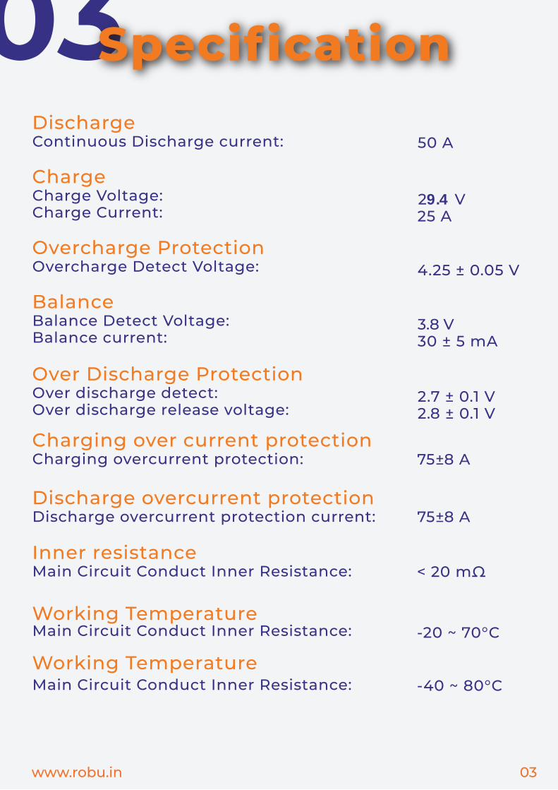
03 04SpecificationDischargeContinuous Discharge current:
ChargeCharge Voltage: Charge Current:
Overcharge ProtectionOvercharge Detect Voltage:
BalanceBalance Detect Voltage: Balance current:
Over Discharge ProtectionOver discharge detect: Over discharge release voltage:
Charging over current protection Charging overcurrent protection:
Discharge overcurrent protection Discharge overcurrent protection current:
Inner resistanceMain Circuit Conduct Inner Resistance:
Main Circuit Conduct Inner Resistance:
Main Circuit Conduct Inner Resistance:
Working Temperature
Working Temperature
4.25 ± 0.05 V
< 20 mΩ
-20 ~ 70°C
-40 ~ 80°C
03www.robu.in
50 A
29.4 V25 A
3.8 V30 ± 5 mA
2.7 ± 0.1 V2.8 ± 0.1 V
75±8 A
75±8 A

04 05Wiring Connection:
Wiring DiagramP+B+
B1 -
B1 +
B2 -
B2 +
B3 -
B3 +
the last B -
the last B +P-
charg
er
Load
B-Total Negative
Battery Pack
Total PositiveCable
P-
B--
+
PCB/BMS for Lithium Battery
04www.robu.in
P-
B--
+
NTC PH2. 0-2P CAN/RS485 PH2.0 0-5
GPS/ PH2. 0-6P
Bluetooth
Ph2.0 0-8P
Charge Indication
PH2. 0-2P PH2. 0-2P
65m
m
13mm
128mm
Activate Soft Switch
DIO PH2. 0-3P
P-
B-
7AWG M6 85mm
7AWG M6 85mm
Connector ph2.0Buckles

051) First connect the B-cable of the protection board to the total negative pole of the battery pack. 2) The cable starts f rom the thin black one connecting B-, the second red cable connects the positive pole of the first string of batteries, and the next string is connected in turn. The positive pole of the pool; then insert the cable into the protection board. 3) After finishing the wiring soldering, measure whether the battery B+, B-voltage and P+,P-voltage values are the same, only same, the protection board works positively. Otherwise. Please follow the above re-operation; 4) When removing the protection board, first pull out the cable (if there are two cables, pull the high-voltage cable first, then pull the low-voltage cable), then remove Power cable B-
Wiring Operation
05www.robu.in

06All our produced Lithium battery BMS, we guarantee 1 year’s warranty in quality, except the damage caused due to Improper human Operation.
Warranty
1) Lithium battery BMS with different voltage range which cannot be mixed using., LifePo4 BMS cannot be used for Li-ion battery.
3) When testing, installing, contacting, and using the protective board, take measures to put static electricity on it.
4) Mustn’t let the heat dissipation surface of the protection board directly contact the battery core, otherwise the heat will be transmitted to the battery core, which will affect the safety of the battery.
5) Do not disassemble or change the components of the protection board by yourself.
6) The metal heat sink of the protection board of the company is anodized and insulated, and the oxide layer will still be conductive after being destroyed. Avoid contact between the heat sink and the battery core and the nickel strip
7) If the protection board is abnormal, please stop using it. Then use it again after it is checked with OK.
8) Do not use the two protective boards in series or in parallel.
Attention
06www.robu.in