CEL-FI QUATRA - Signal Boosters · Cel-Fi QUATRA Range Extender (QRE) Model: Q34-E1000 Cel-Fi...
32
CEL-FI QUATRA ® Installation and User Guide Nextivity, Inc. 16550 West Bernardo Ct Building 5, Suite 550 San Diego, CA 92127 858-485-9442 [email protected]
Transcript of CEL-FI QUATRA - Signal Boosters · Cel-Fi QUATRA Range Extender (QRE) Model: Q34-E1000 Cel-Fi...
CEL-FI QUATRA® Installation and User Guide
Nextivity, Inc.
16550 West Bernardo Ct Building 5, Suite 550 San Diego, CA 92127
858-485-9442 [email protected]
Cel-Fi QUATRA: User Manual 2
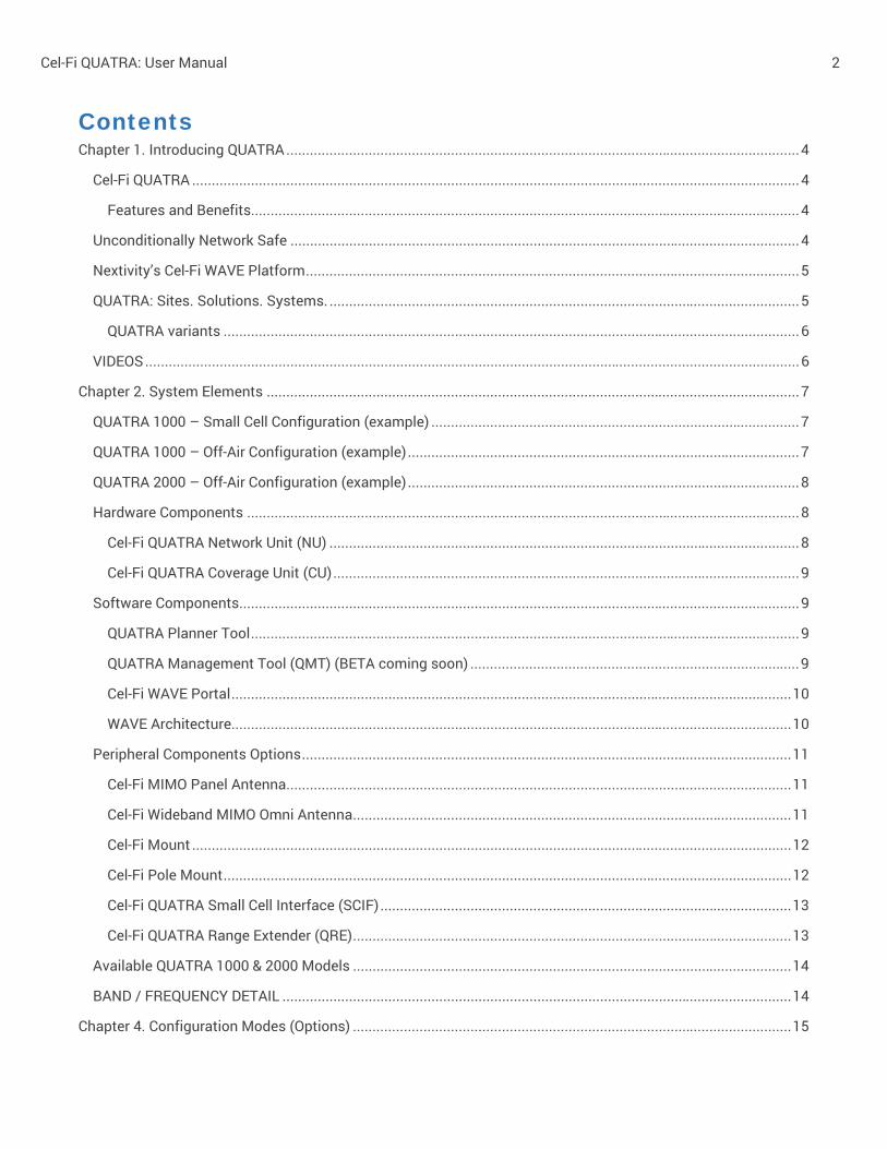
Contents Chapter 1. Introducing QUATRA ................................................................................................................................... 4
Cel-Fi QUATRA ........................................................................................................................................................... 4
Features and Benefits............................................................................................................................................ 4
Unconditionally Network Safe .................................................................................................................................. 4
Nextivity’s Cel-Fi WAVE Platform .............................................................................................................................. 5
QUATRA: Sites. Solutions. Systems. ........................................................................................................................ 5
QUATRA variants ................................................................................................................................................... 6
VIDEOS ....................................................................................................................................................................... 6
Chapter 2. System Elements ........................................................................................................................................ 7
QUATRA 1000 – Small Cell Configuration (example) .............................................................................................. 7
QUATRA 1000 – Off-Air Configuration (example) .................................................................................................... 7
QUATRA 2000 – Off-Air Configuration (example) .................................................................................................... 8
Hardware Components ............................................................................................................................................. 8
Cel-Fi QUATRA Network Unit (NU) ........................................................................................................................ 8
Cel-Fi QUATRA Coverage Unit (CU) ....................................................................................................................... 9
Software Components ............................................................................................................................................... 9
QUATRA Planner Tool ............................................................................................................................................ 9
QUATRA Management Tool (QMT) (BETA coming soon) .................................................................................... 9
Cel-Fi WAVE Portal ............................................................................................................................................... 10
WAVE Architecture ............................................................................................................................................... 10
Peripheral Components Options ............................................................................................................................. 11
Cel-Fi MIMO Panel Antenna ................................................................................................................................. 11
Cel-Fi Wideband MIMO Omni Antenna ................................................................................................................ 11
Cel-Fi Mount ......................................................................................................................................................... 12
Cel-Fi Pole Mount ................................................................................................................................................. 12
Cel-Fi QUATRA Small Cell Interface (SCIF) ......................................................................................................... 13
Cel-Fi QUATRA Range Extender (QRE) ................................................................................................................ 13
Available QUATRA 1000 & 2000 Models ................................................................................................................ 14
BAND / FREQUENCY DETAIL .................................................................................................................................. 14
Chapter 4. Configuration Modes (Options) ................................................................................................................ 15

Cel-Fi QUATRA: User Manual 3
Off-Air ....................................................................................................................................................................... 15
Selecting the Right Donor Antenna ..................................................................................................................... 15
Small Cell (Supercell) .............................................................................................................................................. 16
Determining the Proper Configuration .................................................................................................................... 17
Chapter 5. Deploying Cel-Fi QUATRA ......................................................................................................................... 18
Plan .......................................................................................................................................................................... 18
Planning – Step 1. Site Survey ............................................................................................................................ 18
Planning – Step 2. Estimating Hardware Needs ................................................................................................ 19
Planning – Step 3. Determine NU Donor (Off Air or Small Cell) Location ......................................................... 19
Planning – Step 4. NU Internet Connection & WAVE Portal Account ............................................................... 20
Planning – Step 5. Coverage Unit (CU) Placement ............................................................................................ 20
Planning – Step 6. Coverage Unit Cabling .......................................................................................................... 21
Install ........................................................................................................................................................................ 22
Cable ........................................................................................................................................................................ 24
Power ....................................................................................................................................................................... 25
Chapter 6. Troubleshooting ........................................................................................................................................ 26
Chapter 7. Terminology ............................................................................................................................................... 28
Chapter 8. Specifications ............................................................................................................................................ 30
Version ......................................................................................................................................................................... 31
Cel-Fi QUATRA: User Manual 4
CHAPTER 1. INTRODUCING QUATRA
Cel-Fi QUATRA
In-Building Enterprise Cellular System Cel-Fi QUATRA is an active DAS hybrid solution for delivering high quality in-building cellar coverage. Through the combination of the best of active DAS and Cel-Fi technology that has been widely adopted by carriers around the world, Cel-Fi QUATRA is a scalable solution that provides configurations for single or multi-carrier environments. Options are available for off-air mode or via integration with carrier small cell equipment and operated in distributed small cell mode, creating a Supercell.
Cel-Fi QUATRA is self-configuring and self-optimizing, distributes RF over Ethernet (RFoE), and leverages Power over Ethernet (PoE) for ease and accuracy of installation by Cel-Fi Certified professionals. The system can be monitored and managed using the Cel-Fi WAVE Platform.
Features and Benefits Improves cellular reception for venues from
15,000 to 50,000 sq. ft. per system
Built for streamlined installation and maintenance by Cel-Fi Certified professional
Carrier approved and unconditionally network safe for voice and data
Intelligently self-configures and continually self-optimizes to adapt to environmental changes
AntennaBoost intelligent antenna aiming optimizes signal quality (QUATRA 1000)
Remote monitoring and management using the Cel-Fi WAVE Platform
Off air donor signal
Small cell donor (QUATRA 1000 only)
Best quality signal at 100 dB max gain in off-air mode
Nextivity’s IntelliBoost™ Six-Core Processor supports 3G/4G speeds with low power consumption
Advanced proprietary digital echo-cancellation and channel select filtering algorithms
Automatic Gain Control (AGC) continually and dynamically maximizes system power
Adaptive signal equalization
Seamless integration with the macro network; improves network efficiency without causing interference
Only one power outlet needed per system (at the NU)
Supporting peripherals available (antennas, mounts, range extenders, etc.)
Unconditionally Network Safe Cel-Fi QUATRA provides a sophisticated network-safe design that has been engineered to deliver multiple levels of carrier-grade network protection:
Uplink power control to prevent desensitizing the network
Echo-cancellation and feedback control
Uplink gating
Signal qualification (channels are individually qualified, so noise or very poor signals won’t be amplified and degrade the network)

5
Nextivity’s Cel-Fi WAVE Platform The Cel-Fi WAVE Platform enables device management and maintenance of Cel-Fi QUATRA systems. Alerts and alarms can be used as configured out of the box or they can be customized however the owner or admin chooses.
QUATRA: Sites. Solutions. Systems.
A QUATRA system is comprised of a Network Unit (NU) and one to four Coverage Units (CU). An NU and CU are paired; they must be of the same model, and band configuration. Multiple QUATRA systems can be installed together to form a larger solution. Systems can be attached to a specific site in WAVE, and managed accordingly. A site represents a physical location, in WAVE; an address.

6
Note:
There is no technical limitation to the number of systems or solutions that can be installed together at a site.
QUATRA variants QUATRA 1000 QUATRA 2000
Active DAS Hybrid
Unconditionally Network Safe
100dB System Gain
Distributed over Cat 5e cable
Power over Ethernet (POE)
12.5K ft2 per Coverage Unit
MIMO
Small Cell compatible
Dual-Carrier
VIDEOS Cel-Fi Intro Video
https://youtu.be/Jy6PFhip3SM
Small Cell Planning https://youtu.be/SURNn6vk-_E
Off-Air Planning https://youtu.be/QoMk4XNu47E
Small Cell Install https://youtu.be/ZP8LeQ8YQMc
Off-Air Install https://youtu.be/-Esb0DhkgG4
Small Cell Commissioning https://youtu.be/tpZe1c2KdMw
Off-Air Commissioning https://youtu.be/gFhWN_6wqwI
7
CHAPTER 2. SYSTEM ELEMENTS
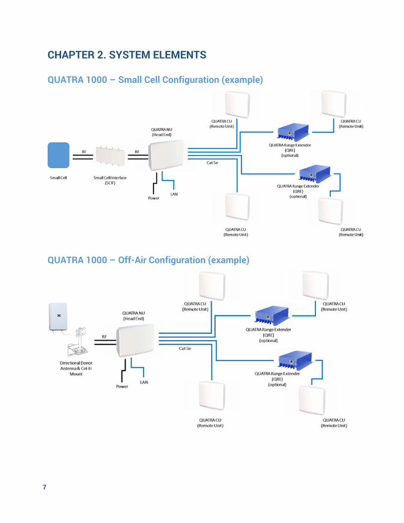
QUATRA 1000 – Small Cell Configuration (example)
QUATRA 1000 – Off-Air Configuration (example)
8
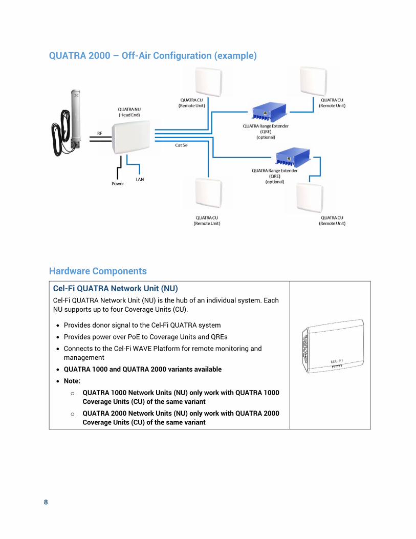
QUATRA 2000 – Off-Air Configuration (example)
Hardware Components
Cel-Fi QUATRA Network Unit (NU) Cel-Fi QUATRA Network Unit (NU) is the hub of an individual system. Each NU supports up to four Coverage Units (CU).
Provides donor signal to the Cel-Fi QUATRA system
Provides power over PoE to Coverage Units and QREs
Connects to the Cel-Fi WAVE Platform for remote monitoring and management
QUATRA 1000 and QUATRA 2000 variants available
Note:
o QUATRA 1000 Network Units (NU) only work with QUATRA 1000 Coverage Units (CU) of the same variant
o QUATRA 2000 Network Units (NU) only work with QUATRA 2000 Coverage Units (CU) of the same variant
9
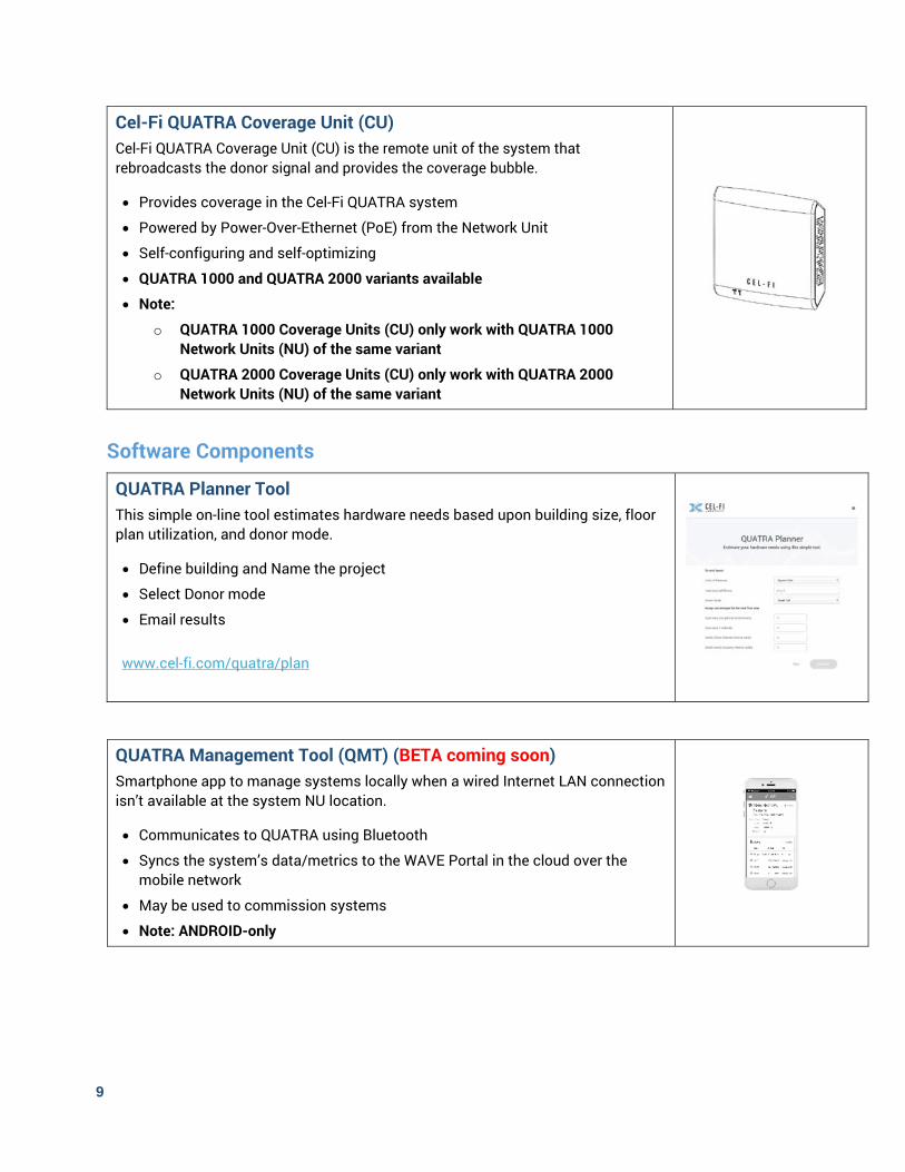
Cel-Fi QUATRA Coverage Unit (CU) Cel-Fi QUATRA Coverage Unit (CU) is the remote unit of the system that rebroadcasts the donor signal and provides the coverage bubble.
Provides coverage in the Cel-Fi QUATRA system
Powered by Power-Over-Ethernet (PoE) from the Network Unit
Self-configuring and self-optimizing
QUATRA 1000 and QUATRA 2000 variants available
Note:
o QUATRA 1000 Coverage Units (CU) only work with QUATRA 1000 Network Units (NU) of the same variant
o QUATRA 2000 Coverage Units (CU) only work with QUATRA 2000 Network Units (NU) of the same variant
Software Components
QUATRA Planner Tool This simple on-line tool estimates hardware needs based upon building size, floor plan utilization, and donor mode.
Define building and Name the project
Select Donor mode
Email results
www.cel-fi.com/quatra/plan
QUATRA Management Tool (QMT) (BETA coming soon) Smartphone app to manage systems locally when a wired Internet LAN connection isn’t available at the system NU location.
Communicates to QUATRA using Bluetooth
Syncs the system’s data/metrics to the WAVE Portal in the cloud over the mobile network
May be used to commission systems
Note: ANDROID-only
10
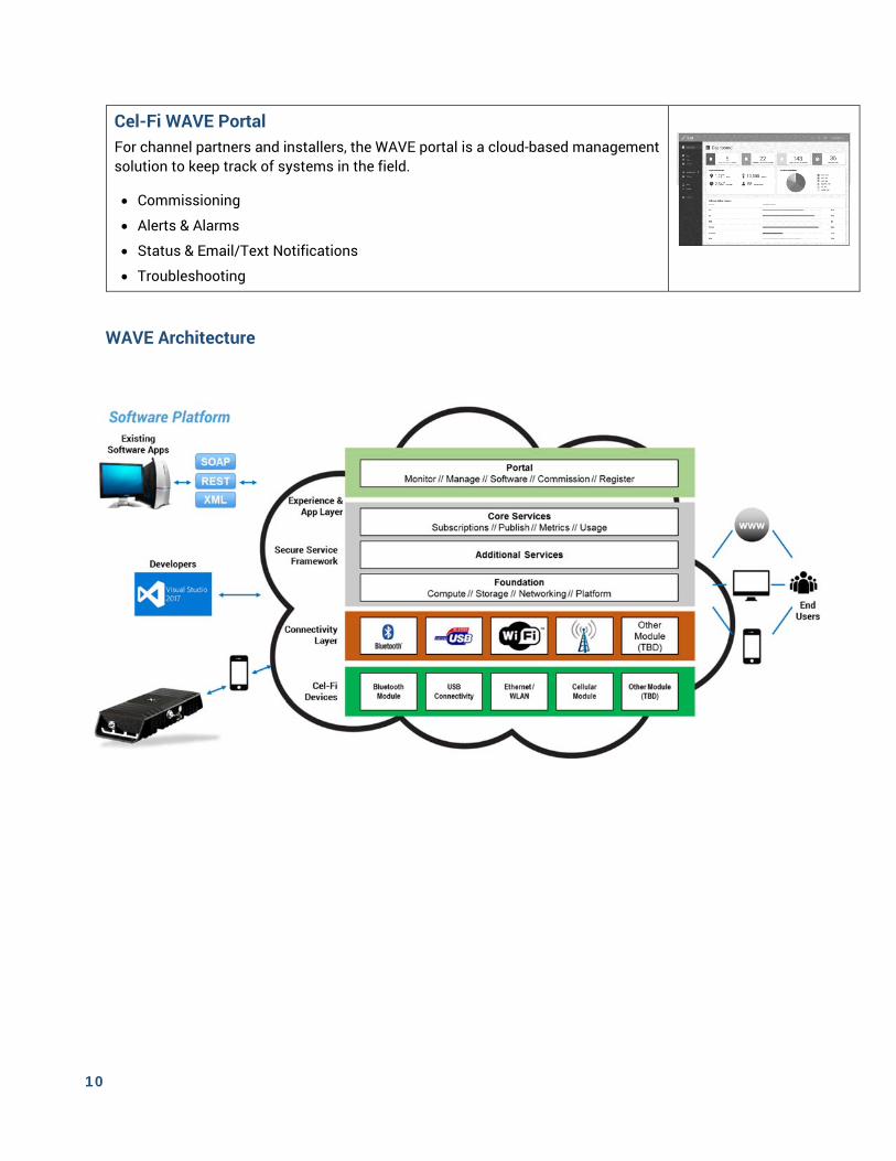
Cel-Fi WAVE Portal For channel partners and installers, the WAVE portal is a cloud-based management solution to keep track of systems in the field.
Commissioning
Alerts & Alarms
Status & Email/Text Notifications
Troubleshooting
WAVE Architecture

11
Peripheral Components Options A number of peripheral component options are available for QUATRA from Nextivity and Nextivity’s partners. Check the web site regularly for updates.
www.cel-fi.com/quatra
Cel-Fi MIMO Panel Antenna Model: A52-X12-100
The Cel-Fi MIMO Panel Antenna is the only authorized indoor/outdoor MIMO antenna for Cel-Fi QUATRA 1000.
High gain directional MIMO panel antenna
Donor managed with AntennaBoost’s 8-position aiming mount
Includes options for ceiling, wall, and pole mounting
Required for off-air installation of multiple CUs
Works best with:
QUATRA 1000
Cel-Fi Wideband MIMO Omni Antenna Model:
Cel-Fi Wideband MIMO Omni Antenna is an outdoor-rated cellular antenna, perfect for use as a donor antenna for Cel-Fi QUATRA 2000.
698 MHZ - 2700 MHz
MIMO (dual RF feeds)
N-type Female connectors
Works best with:
QUATRA 2000
12
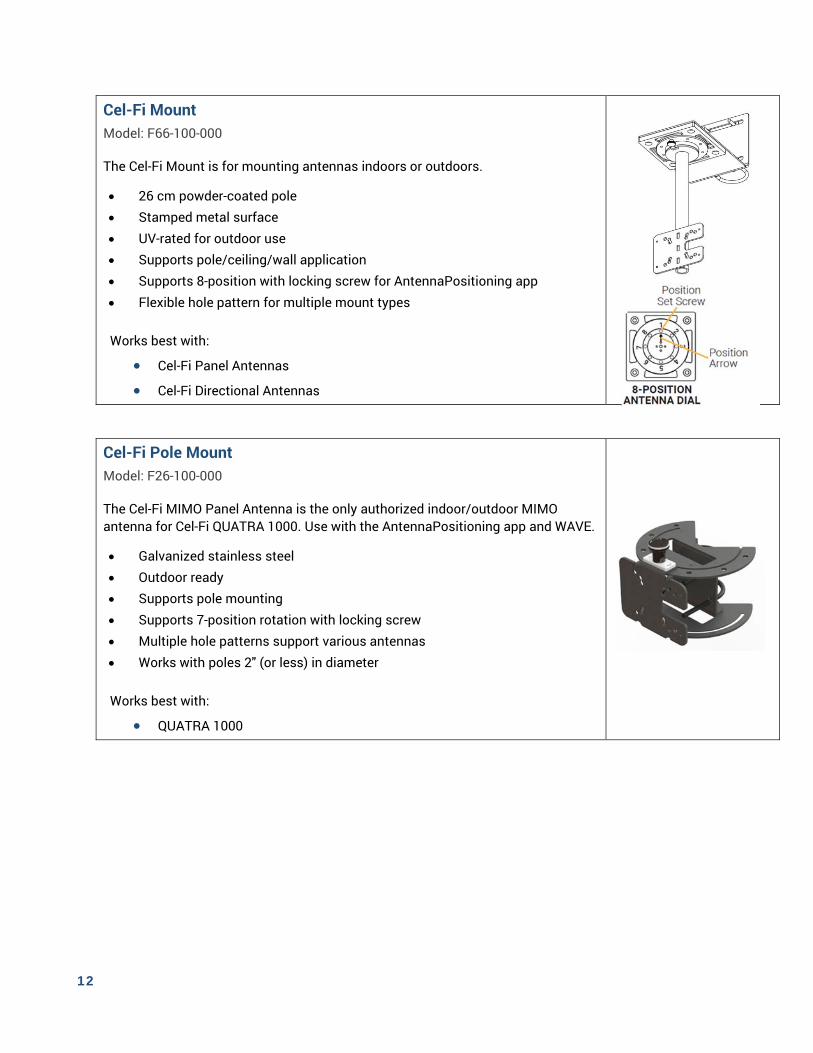
Cel-Fi Mount Model: F66-100-000
The Cel-Fi Mount is for mounting antennas indoors or outdoors.
26 cm powder-coated pole Stamped metal surface UV-rated for outdoor use Supports pole/ceiling/wall application Supports 8-position with locking screw for AntennaPositioning app Flexible hole pattern for multiple mount types
Works best with:
Cel-Fi Panel Antennas Cel-Fi Directional Antennas
Cel-Fi Pole Mount Model: F26-100-000
The Cel-Fi MIMO Panel Antenna is the only authorized indoor/outdoor MIMO antenna for Cel-Fi QUATRA 1000. Use with the AntennaPositioning app and WAVE.
Galvanized stainless steel Outdoor ready Supports pole mounting Supports 7-position rotation with locking screw Multiple hole patterns support various antennas Works with poles 2" (or less) in diameter
Works best with:
QUATRA 1000
13
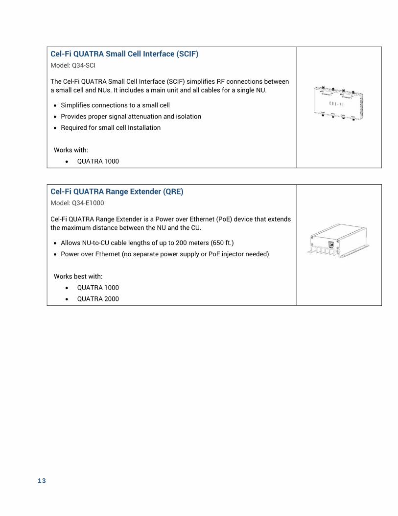
Cel-Fi QUATRA Small Cell Interface (SCIF) Model: Q34-SCI
The Cel-Fi QUATRA Small Cell Interface (SCIF) simplifies RF connections between a small cell and NUs. It includes a main unit and all cables for a single NU.
Simplifies connections to a small cell
Provides proper signal attenuation and isolation
Required for small cell Installation
Works with:
QUATRA 1000
Cel-Fi QUATRA Range Extender (QRE) Model: Q34-E1000
Cel-Fi QUATRA Range Extender is a Power over Ethernet (PoE) device that extends the maximum distance between the NU and the CU.
Allows NU-to-CU cable lengths of up to 200 meters (650 ft.)
Power over Ethernet (no separate power supply or PoE injector needed)
Works best with:
QUATRA 1000
QUATRA 2000
14
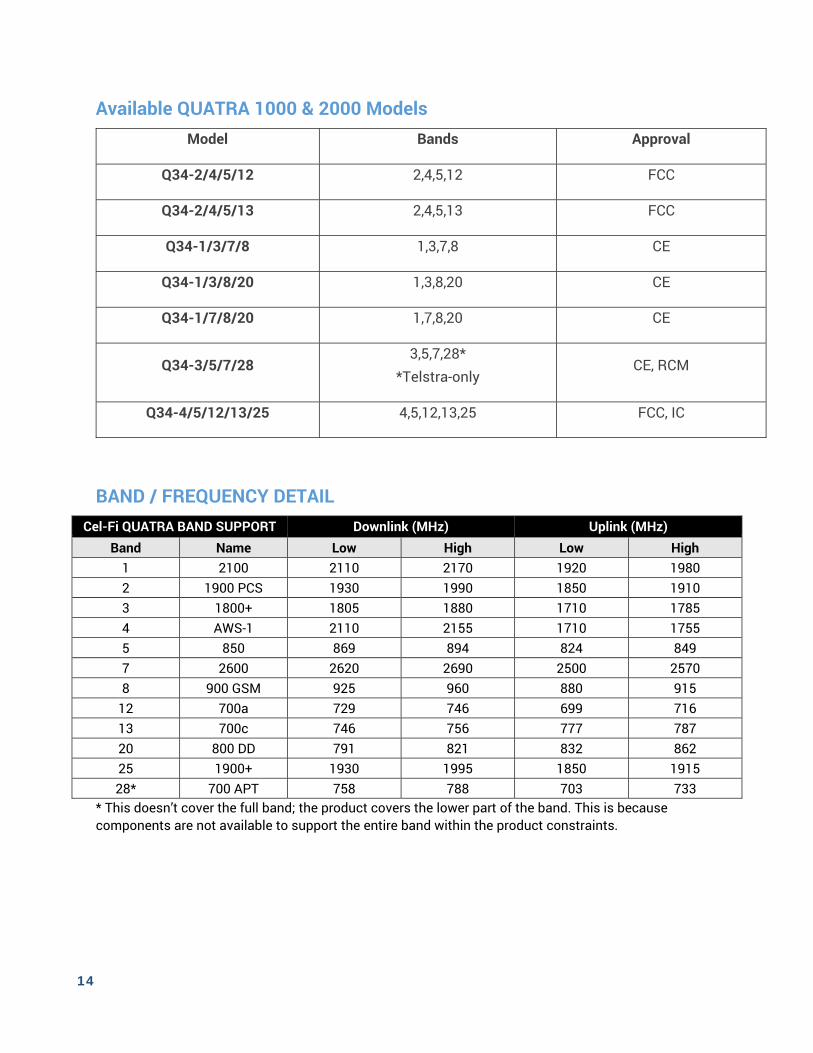
Available QUATRA 1000 & 2000 Models Model Bands Approval
Q34-2/4/5/12 2,4,5,12 FCC
Q34-2/4/5/13 2,4,5,13 FCC
Q34-1/3/7/8 1,3,7,8 CE
Q34-1/3/8/20 1,3,8,20 CE
Q34-1/7/8/20 1,7,8,20 CE
Q34-3/5/7/28 3,5,7,28*
*Telstra-only CE, RCM
Q34-4/5/12/13/25 4,5,12,13,25 FCC, IC
BAND / FREQUENCY DETAIL Cel-Fi QUATRA BAND SUPPORT Downlink (MHz) Uplink (MHz)
Band Name Low High Low High 1 2100 2110 2170 1920 1980 2 1900 PCS 1930 1990 1850 1910 3 1800+ 1805 1880 1710 1785 4 AWS-1 2110 2155 1710 1755 5 850 869 894 824 849 7 2600 2620 2690 2500 2570 8 900 GSM 925 960 880 915
12 700a 729 746 699 716 13 700c 746 756 777 787 20 800 DD 791 821 832 862 25 1900+ 1930 1995 1850 1915 28* 700 APT 758 788 703 733
* This doesn’t cover the full band; the product covers the lower part of the band. This is because components are not available to support the entire band within the product constraints.
15
CHAPTER 4. CONFIGURATION MODES (OPTIONS)
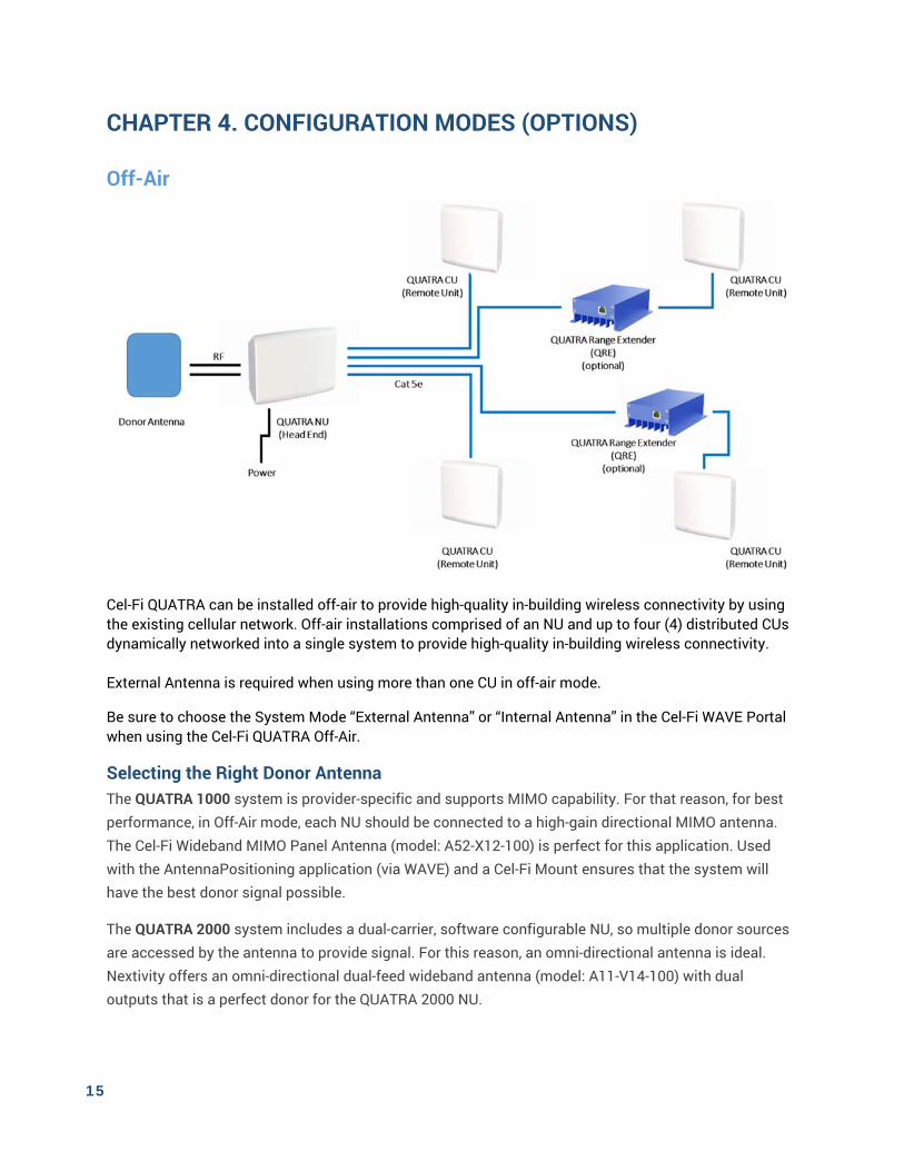
Off-Air
Cel-Fi QUATRA can be installed off-air to provide high-quality in-building wireless connectivity by using the existing cellular network. Off-air installations comprised of an NU and up to four (4) distributed CUs dynamically networked into a single system to provide high-quality in-building wireless connectivity. External Antenna is required when using more than one CU in off-air mode.
Be sure to choose the System Mode “External Antenna” or “Internal Antenna” in the Cel-Fi WAVE Portal when using the Cel-Fi QUATRA Off-Air.
Selecting the Right Donor Antenna The QUATRA 1000 system is provider-specific and supports MIMO capability. For that reason, for best performance, in Off-Air mode, each NU should be connected to a high-gain directional MIMO antenna. The Cel-Fi Wideband MIMO Panel Antenna (model: A52-X12-100) is perfect for this application. Used with the AntennaPositioning application (via WAVE) and a Cel-Fi Mount ensures that the system will have the best donor signal possible.
The QUATRA 2000 system includes a dual-carrier, software configurable NU, so multiple donor sources are accessed by the antenna to provide signal. For this reason, an omni-directional antenna is ideal. Nextivity offers an omni-directional dual-feed wideband antenna (model: A11-V14-100) with dual outputs that is a perfect donor for the QUATRA 2000 NU.
16
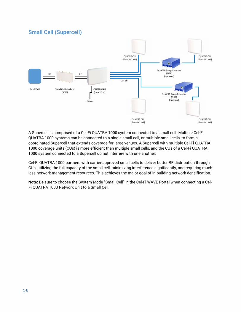
Small Cell (Supercell)
A Supercell is comprised of a Cel-Fi QUATRA 1000 system connected to a small cell. Multiple Cel-Fi QUATRA 1000 systems can be connected to a single small cell, or multiple small cells, to form a coordinated Supercell that extends coverage for large venues. A Supercell with multiple Cel-Fi QUATRA 1000 coverage units (CUs) is more efficient than multiple small cells, and the CUs of a Cel-Fi QUATRA 1000 system connected to a Supercell do not interfere with one another.
Cel-Fi QUATRA 1000 partners with carrier-approved small cells to deliver better RF distribution through CUs, utilizing the full capacity of the small cell, minimizing interference significantly, and requiring much less network management resources. This achieves the major goal of in-building network densification.
Note: Be sure to choose the System Mode “Small Cell” in the Cel-Fi WAVE Portal when connecting a Cel-Fi QUATRA 1000 Network Unit to a Small Cell.
17
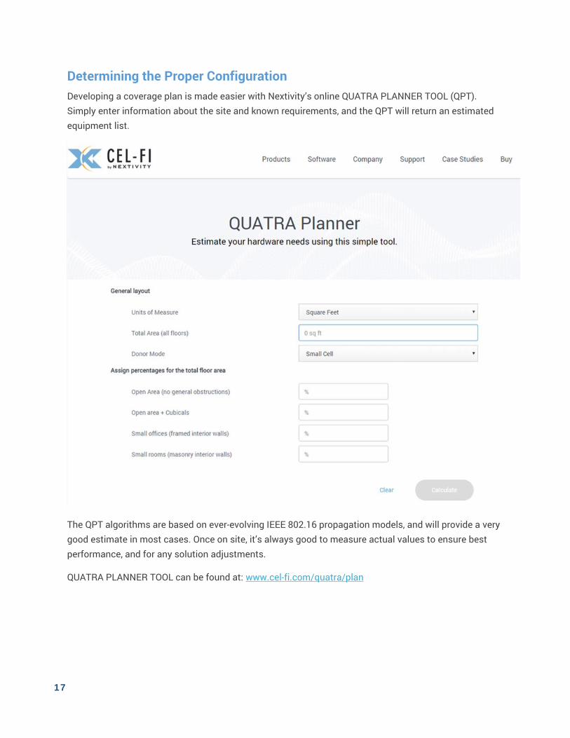
Determining the Proper Configuration Developing a coverage plan is made easier with Nextivity’s online QUATRA PLANNER TOOL (QPT). Simply enter information about the site and known requirements, and the QPT will return an estimated equipment list.
The QPT algorithms are based on ever-evolving IEEE 802.16 propagation models, and will provide a very good estimate in most cases. Once on site, it’s always good to measure actual values to ensure best performance, and for any solution adjustments.
QUATRA PLANNER TOOL can be found at: www.cel-fi.com/quatra/plan
18
CHAPTER 5. DEPLOYING CEL-FI QUATRA
Plan To facilitate the installation process and the best performance at the site, it’s important to plan the system design prior to any permanent installations.
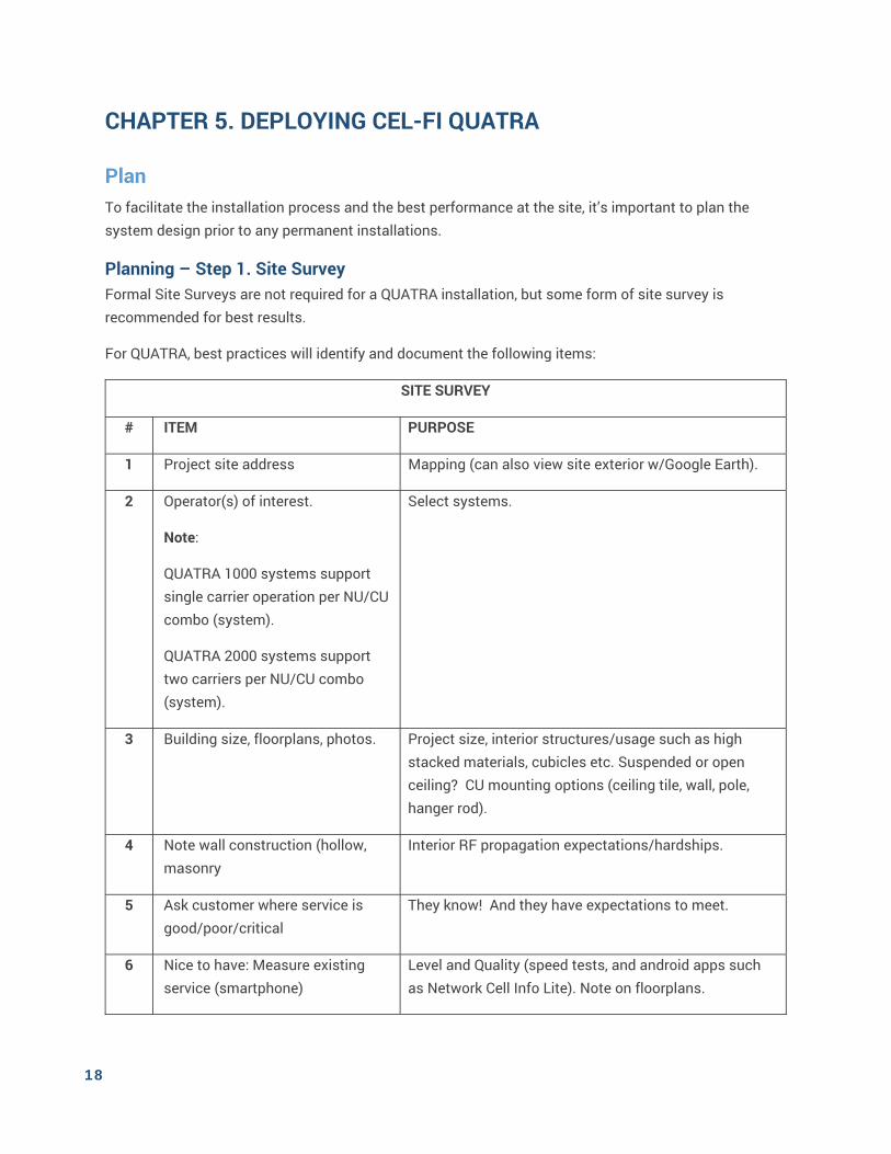
Planning – Step 1. Site Survey Formal Site Surveys are not required for a QUATRA installation, but some form of site survey is recommended for best results.
For QUATRA, best practices will identify and document the following items:
SITE SURVEY
# ITEM PURPOSE
1 Project site address Mapping (can also view site exterior w/Google Earth).
2 Operator(s) of interest.
Note:
QUATRA 1000 systems support single carrier operation per NU/CU combo (system).
QUATRA 2000 systems support two carriers per NU/CU combo (system).
Select systems.
3 Building size, floorplans, photos. Project size, interior structures/usage such as high stacked materials, cubicles etc. Suspended or open ceiling? CU mounting options (ceiling tile, wall, pole, hanger rod).
4 Note wall construction (hollow, masonry
Interior RF propagation expectations/hardships.
5 Ask customer where service is good/poor/critical
They know! And they have expectations to meet.
6 Nice to have: Measure existing service (smartphone)
Level and Quality (speed tests, and android apps such as Network Cell Info Lite). Note on floorplans.
19
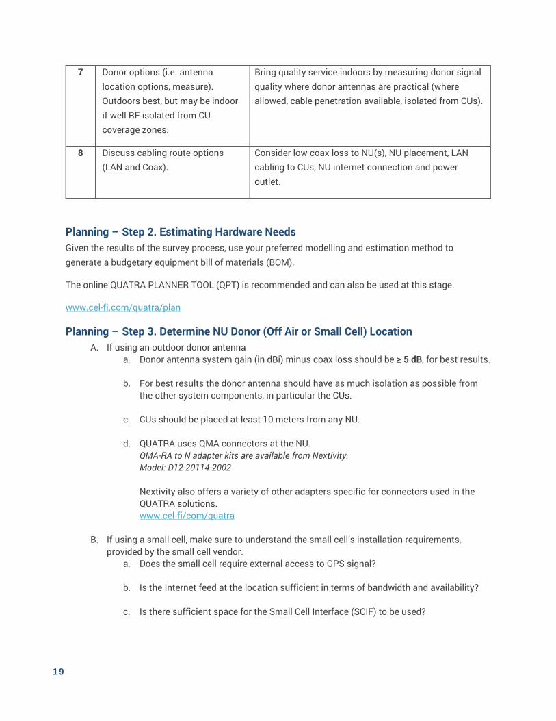
7 Donor options (i.e. antenna location options, measure). Outdoors best, but may be indoor if well RF isolated from CU coverage zones.
Bring quality service indoors by measuring donor signal quality where donor antennas are practical (where allowed, cable penetration available, isolated from CUs).
8 Discuss cabling route options (LAN and Coax).
Consider low coax loss to NU(s), NU placement, LAN cabling to CUs, NU internet connection and power outlet.
Planning – Step 2. Estimating Hardware Needs Given the results of the survey process, use your preferred modelling and estimation method to generate a budgetary equipment bill of materials (BOM).
The online QUATRA PLANNER TOOL (QPT) is recommended and can also be used at this stage.
www.cel-fi.com/quatra/plan
Planning – Step 3. Determine NU Donor (Off Air or Small Cell) Location A. If using an outdoor donor antenna
a. Donor antenna system gain (in dBi) minus coax loss should be ≥ 5 dB, for best results.
b. For best results the donor antenna should have as much isolation as possible from the other system components, in particular the CUs.
c. CUs should be placed at least 10 meters from any NU.
d. QUATRA uses QMA connectors at the NU. QMA-RA to N adapter kits are available from Nextivity. Model: D12-20114-2002 Nextivity also offers a variety of other adapters specific for connectors used in the QUATRA solutions. www.cel-fi/com/quatra
B. If using a small cell, make sure to understand the small cell’s installation requirements, provided by the small cell vendor.
a. Does the small cell require external access to GPS signal?
b. Is the Internet feed at the location sufficient in terms of bandwidth and availability?
c. Is there sufficient space for the Small Cell Interface (SCIF) to be used?
20
C. If using an indoor donor antenna (QUATRA 1000 only), it is recommended that the antenna be located close to the NU for best performance and minimal loss from antenna to NU. Note: The NU+ANT should be well isolated from all CUs (walls etc.), to ensure full CU transmit power.
Planning – Step 4. NU Internet Connection & WAVE Portal Account Network Unit requirements:
o Power
o Internet Access via LAN port Note: Make sure IT Staff can assist with any LAN issues if needed. A LAN
Connection Guide is available on request. A variety of sources for Internet connectivity hardware are available.
Options include: 3GSTORE: https://3gstore.com/quatra_routers MULTITECH: https://www.multitech.com/products/gateways-routers-
modems DIGI: https://www.digi.com/products/cellular-solutions
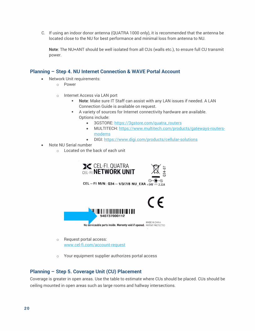
Note NU Serial number o Located on the back of each unit
o Request portal access: www.cel-fi.com/account-request
o Your equipment supplier authorizes portal access
Planning – Step 5. Coverage Unit (CU) Placement Coverage is greater in open areas. Use the table to estimate where CUs should be placed. CUs should be ceiling mounted in open areas such as large rooms and hallway intersections.

21
Coverage Area Radius (estimated, meters)
Area Type Small Cell Mode
External Antenna Mode (Outdoor Donor)
External Antenna Mode (Indoor Donor)
Open Area (no general obstructions)
24 24 20
Open Area + Cubicles 20 20 16
Small Offices (framed interior walls)
16 16 13
Small Rooms (masonry interior walls)
12 12 9
Note: Each CU has QMA-Female RF ports (x2). Passive antennas may be connected to these ports to provide additional coverage options. Typical passive RF cabling and antenna restrictions apply.
Planning – Step 6. Coverage Unit Cabling Determine how many cables may be needed for the planned Coverage Units.
Each CU requires a dedicated cable to the Network Unit o Active Ethernet hubs such as switches or routers may not be used
Cables must be Cat 5e or better (Gigabit compliant)
No cable may exceed 100m (325 ft.)
You may use one QRE per CU to extend range to 200m (650 ft.)
OK to use existing LAN cables (rather than run new cables), if they meet the minimum
requirements
EXPERT TIP: CHECK YOUR PLAN AGAINST THESE RULES
CUs should be at least 10 meters (33 feet) away from any Network Unit
The donor antenna should be very well isolated from all CUs (50m min; less if well separated by walls or solid structures)
If locating the donor antenna away from the Network Unit (roof etc.) use low loss cable and keep antenna system gain (antenna gain minus cable loss) to no less than 3-5 dB.
22
Install 1. Record serial numbers by location
The QUATRA Management tools, including the WAVE Portal, will reference the NUs and CUs by serial number during commissioning.
Friendly-names may be assigned during the commissioning process.
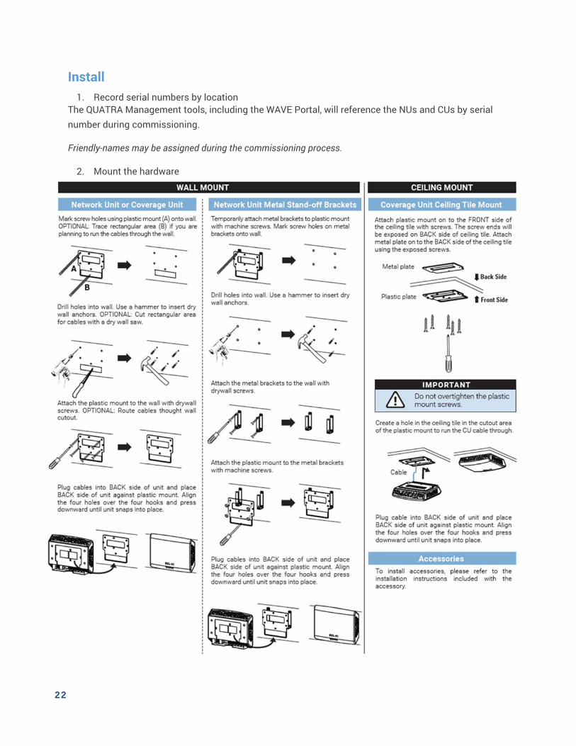
2. Mount the hardware
23
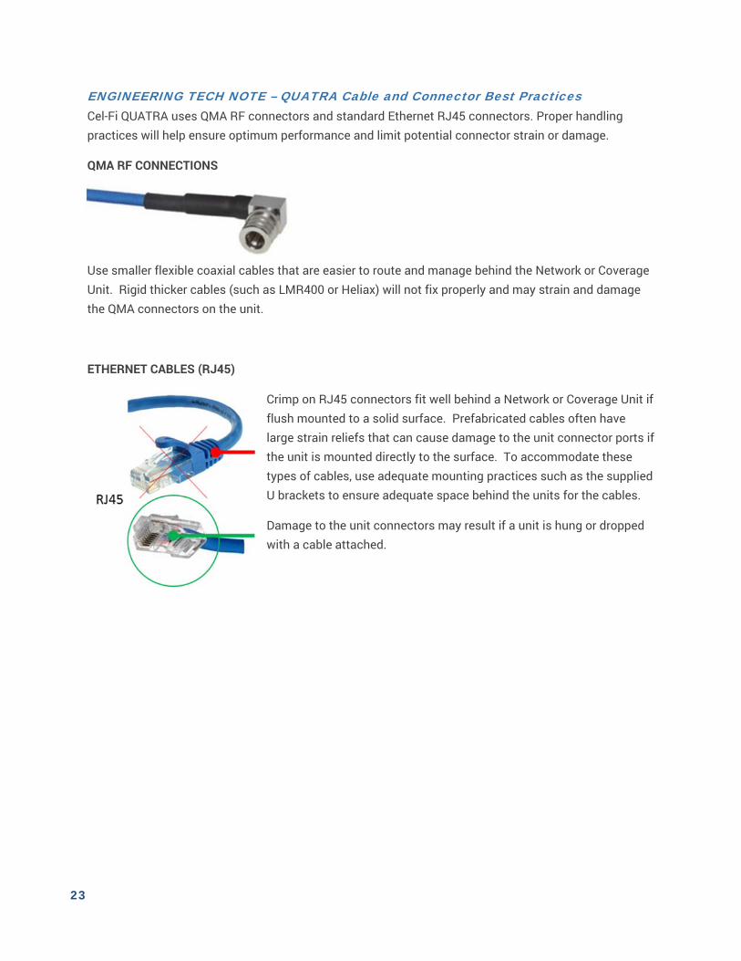
ENGINEERING TECH NOTE – QUATRA Cable and Connector Best Practices Cel-Fi QUATRA uses QMA RF connectors and standard Ethernet RJ45 connectors. Proper handling practices will help ensure optimum performance and limit potential connector strain or damage.
QMA RF CONNECTIONS
Use smaller flexible coaxial cables that are easier to route and manage behind the Network or Coverage Unit. Rigid thicker cables (such as LMR400 or Heliax) will not fix properly and may strain and damage the QMA connectors on the unit.
ETHERNET CABLES (RJ45)
Crimp on RJ45 connectors fit well behind a Network or Coverage Unit if flush mounted to a solid surface. Prefabricated cables often have large strain reliefs that can cause damage to the unit connector ports if the unit is mounted directly to the surface. To accommodate these types of cables, use adequate mounting practices such as the supplied U brackets to ensure adequate space behind the units for the cables.
Damage to the unit connectors may result if a unit is hung or dropped with a cable attached.
24
Cable Route and connect all cables.
NU to CU cabling. (Recommended) Connect CUs in order, CU1, CU2, etc.
(Recommended) Best practices to leave a service loop in the cable, for more flexibility with
mounting location. QUATRA CU connections are lossless, so there is no penalty for excess cable (<100m).
Note: Do not power up system at this point.
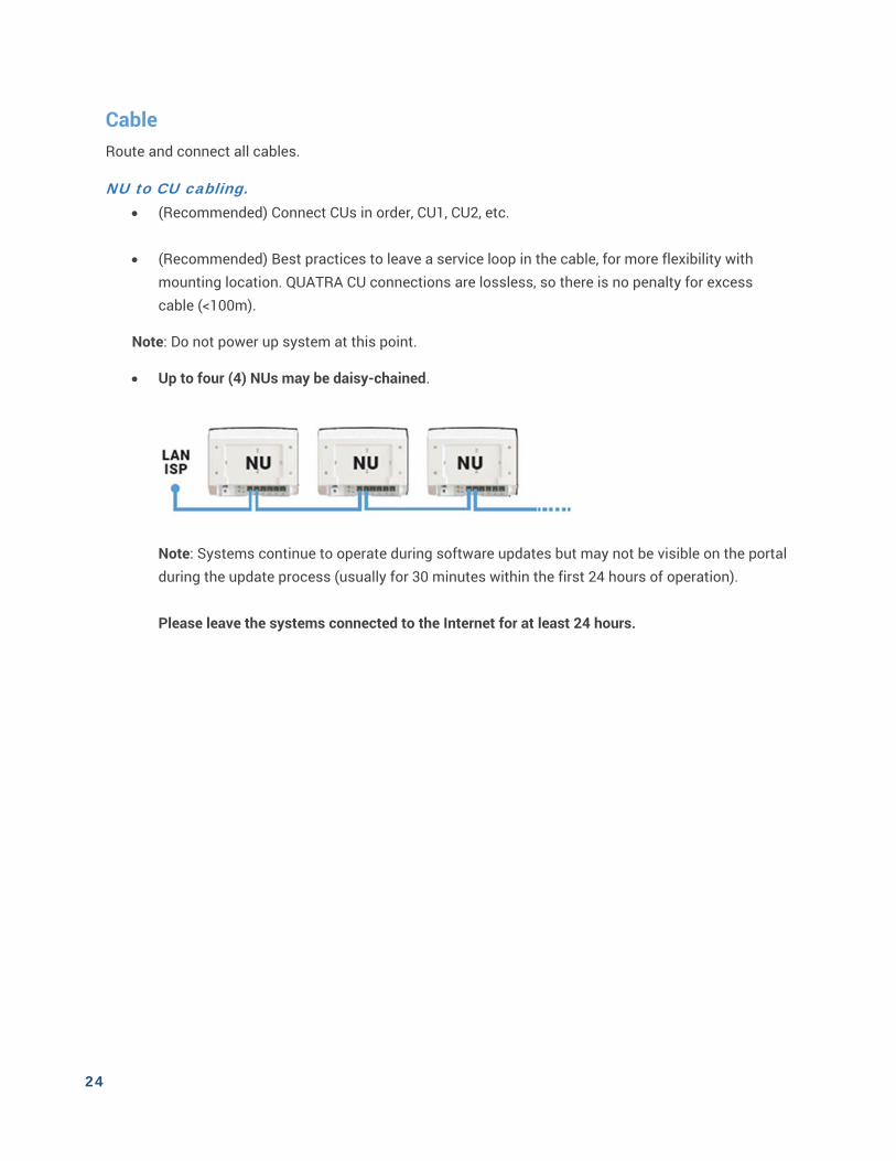
Up to four (4) NUs may be daisy-chained.
Note: Systems continue to operate during software updates but may not be visible on the portal during the update process (usually for 30 minutes within the first 24 hours of operation). Please leave the systems connected to the Internet for at least 24 hours.
25
Power Power the Network Unit and Commission the System
IMPORTANT
There are two ways to commission a QUATRA system 1. Using the WAVE Portal (now) 2. Using the QMT app (coming soon!)
The QMT app is essentially a smart phone app frame for the WAVE Portal Available on Android-only.
Make sure that the NU mode is properly set to Internal Antenna, External Antenna, or Small Cell
using QMT or the Cel-Fi WAVE Portal (you can access your system record using the NU serial number.)
If using a small cell, verify the small cell is commissioned and transmitting before commissioning QUATRA.
1. Once a donor signal is available to the NU and CUs are connected, plug in the NU power supply.
2. QUATRA will communication with the portal via the LAN connection (Internet).
3. Follow the on-screen (WAVE portal) prompts to connect to the Cel-Fi QUATRA system.
4. Complete the commissioning steps. NOTE: If you are commissioning a QUATRA 1000 with a Directional Antenna, the commissioning will include the AntennaPositioning process.
Once commissioning is completed, the Cel-Fi QUATRA system should be providing service.
At this time, LEDs should be SOLID GREEN.
If an LED is blinking GREEN, wait for the process to complete. If an LED is RED, please see Troubleshooting.

26
CHAPTER 6. TROUBLESHOOTING
LED ISSUE TRY
SOLID RED
Network Unit (NU) error.
Reset the Network Unit by unplugging the power supply, wait 5 seconds, then plug it back in. Verify Network Unit software is up to date (using QMT or cloud portal). If the problem persists, return Network Unit for service.
Network Unit overheating.
Make sure that the vents (the small openings in the plastic housing) on the units are not blocked. Move the unit to a cooler area. The system will start working normally when it cools down.
Coverage Unit (CU) error.
Reset the Coverage Unit by unplugging it and then plugging it back in. Verify Coverage Unit software is up to date (using QMT or cloud portal). Make sure that the LAN cabling to each Coverage Unit is dedicated (not combined with other active LAN hardware such as routers and switches). Passive connectors may be used (i.e. punch-down blocks) but the maximum cable distance may be reduced. If a Cel-Fi QUATRA Range Extender is used to lengthen the 100 meter maximum Network Unit to Coverage Unit Ethernet distance, make sure only a single Cel-Fi QUATRA Range Extender (QRE) is used per Coverage Unit. QRE is proprietary and other extenders will not work. See QRE Troubleshooting. Uninstall Coverage Unit and plug it into back of Network Unit with a short Ethernet cable that is known to work. If the Coverage Unit works properly, troubleshoot the original Ethernet cable (or QRE if used). If the problem persists, return Coverage Unit for service.
Coverage Unit overheating.
Make sure that the vents (the small openings in the plastic housing) on the units are not blocked. Move the unit to a cooler area. The system will start working normally when it cools down.
BLINKING RED
Problem with donor signal or Mode setting.
Insufficient Donor Signal. If internal antennas used for Network Unit, relocate Network Unit where signals exist or add and Enable external antennas in Settings. If external antennas or a small cell donor signal are used, check Mode setting, donor source, and cable connections to the NU RF ports.
Registration required.
Product Registration is required for your system to operate (system is new or has been moved to a new address). Please follow the registration instructions using QMT or the Cel-Fi WAVE portal.
Check Mode and number of CUs.
If NU Mode is set to Internal Antenna, only one CU may be used. More connected CUs will result in system Disable. Disconnect additional CUs, or set NU Mode to External Antenna and connect an External Antenna.
No CU connected.
Connect at least one CU to the NU.
CU too close to NU.
A CU is too close to the NU. Move the closest CU further away from the NU.
CU Disabled. Use QMT or the Cel-Fi WAVE portal to Enable the CU if it is Disabled.
Input signal too strong.
The Network Unit is receiving too strong a donor signal and may operate with reduced gain (the signal source could be any Operator’s cell tower if close enough, or it could be another indoor cellular solution in close proximity to the Network Unit donor antennas). If internal antennas used, move the Network Unit to another location. You might need to move your system to the other side of your building. If external antennas used, move or re-aim the external antennas away from the strong cellular signal source.
27
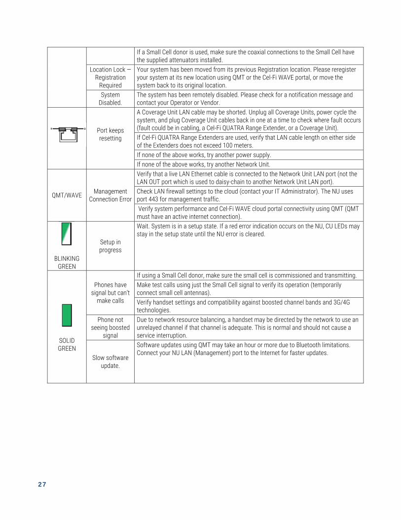
If a Small Cell donor is used, make sure the coaxial connections to the Small Cell have the supplied attenuators installed.
Location Lock — Registration
Required
Your system has been moved from its previous Registration location. Please reregister your system at its new location using QMT or the Cel-Fi WAVE portal, or move the system back to its original location.
System Disabled.
The system has been remotely disabled. Please check for a notification message and contact your Operator or Vendor.
Port keeps resetting
A Coverage Unit LAN cable may be shorted. Unplug all Coverage Units, power cycle the system, and plug Coverage Unit cables back in one at a time to check where fault occurs (fault could be in cabling, a Cel-Fi QUATRA Range Extender, or a Coverage Unit). If Cel-Fi QUATRA Range Extenders are used, verify that LAN cable length on either side of the Extenders does not exceed 100 meters. If none of the above works, try another power supply. If none of the above works, try another Network Unit.
QMT/WAVE Management
Connection Error
Verify that a live LAN Ethernet cable is connected to the Network Unit LAN port (not the LAN OUT port which is used to daisy-chain to another Network Unit LAN port). Check LAN firewall settings to the cloud (contact your IT Administrator). The NU uses port 443 for management traffic. Verify system performance and Cel-Fi WAVE cloud portal connectivity using QMT (QMT must have an active internet connection).
BLINKING GREEN
Setup in progress
Wait. System is in a setup state. If a red error indication occurs on the NU, CU LEDs may stay in the setup state until the NU error is cleared.
SOLID GREEN
Phones have signal but can’t
make calls
If using a Small Cell donor, make sure the small cell is commissioned and transmitting. Make test calls using just the Small Cell signal to verify its operation (temporarily connect small cell antennas). Verify handset settings and compatibility against boosted channel bands and 3G/4G technologies.
Phone not seeing boosted
signal
Due to network resource balancing, a handset may be directed by the network to use an unrelayed channel if that channel is adequate. This is normal and should not cause a service interruption.
Slow software update.
Software updates using QMT may take an hour or more due to Bluetooth limitations. Connect your NU LAN (Management) port to the Internet for faster updates.
28
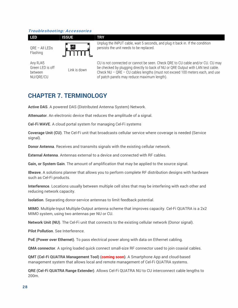
Troubleshooting: Accessories LED ISSUE TRY
QRE – All LEDs Flashing
Unplug the INPUT cable, wait 5 seconds, and plug it back in. If the condition persists the unit needs to be replaced.
Any RJ45 Green LED is off between NU/QRE/CU
Link is down
CU is not connected or cannot be seen. Check QRE to CU cable and/or CU. CU may be checked by plugging directly to back of NU or QRE Output with LAN test cable. Check NU – QRE – CU cables lengths (must not exceed 100 meters each, and use of patch panels may reduce maximum length).
CHAPTER 7. TERMINOLOGY
Active DAS. A powered DAS (Distributed Antenna System) Network.
Attenuator. An electronic device that reduces the amplitude of a signal.
Cel-Fi WAVE. A cloud portal system for managing Cel-Fi systems
Coverage Unit (CU). The Cel-Fi unit that broadcasts cellular service where coverage is needed (Service signal).
Donor Antenna. Receives and transmits signals with the existing cellular network.
External Antenna. Antennas external to a device and connected with RF cables.
Gain, or System Gain. The amount of amplification that may be applied to the source signal.
IBwave. A solutions planner that allows you to perform complete RF distribution designs with hardware such as Cel-Fi products.
Interference. Locations usually between multiple cell sites that may be interfering with each other and reducing network capacity.
Isolation. Separating donor-service antennas to limit feedback potential.
MIMO. Multiple-Input Multiple-Output antenna scheme that improves capacity. Cel-Fi QUATRA is a 2x2 MIMO system, using two antennas per NU or CU.
Network Unit (NU). The Cel-Fi unit that connects to the existing cellular network (Donor signal).
Pilot Pollution. See Interference.
PoE (Power over Ethernet). To pass electrical power along with data on Ethernet cabling.
QMA connector. A spring loaded quick connect small-size RF connector used to join coaxial cables.
QMT (Cel-Fi QUATRA Management Tool) (coming soon). A Smartphone App and cloud-based management system that allows local and remote management of Cel-Fi QUATRA systems.
QRE (Cel-Fi QUATRA Range Extender). Allows Cel-Fi QUATRA NU to CU interconnect cable lengths to 200m.
29
RFoE. The transport of RF signals over Ethernet cable.
Server (also referred to as “Service”) Antenna. Receives and transmits signals amongst local user devices (phones/tablets etc).
SMA Connector. A common small (Sub-Miniature A) 50 ohm RF cable connector.
Small Cell. Low-powered cellular radio access node.
Splitter (Divider/Combiner). Splits a single coaxial cable to/from multiple cables.
30
CHAPTER 8. SPECIFICATIONS
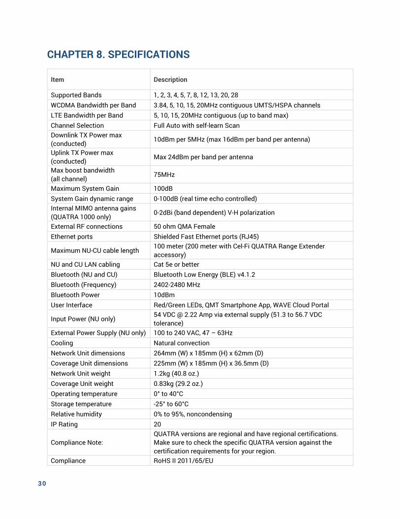
Item Description
Supported Bands 1, 2, 3, 4, 5, 7, 8, 12, 13, 20, 28 WCDMA Bandwidth per Band 3.84, 5, 10, 15, 20MHz contiguous UMTS/HSPA channels LTE Bandwidth per Band 5, 10, 15, 20MHz contiguous (up to band max) Channel Selection Full Auto with self-learn Scan Downlink TX Power max (conducted) 10dBm per 5MHz (max 16dBm per band per antenna)
Uplink TX Power max (conducted) Max 24dBm per band per antenna
Max boost bandwidth (all channel) 75MHz
Maximum System Gain 100dB System Gain dynamic range 0-100dB (real time echo controlled) Internal MIMO antenna gains (QUATRA 1000 only) 0-2dBi (band dependent) V-H polarization
External RF connections 50 ohm QMA Female Ethernet ports Shielded Fast Ethernet ports (RJ45)
Maximum NU-CU cable length 100 meter (200 meter with Cel-Fi QUATRA Range Extender accessory)
NU and CU LAN cabling Cat 5e or better Bluetooth (NU and CU) Bluetooth Low Energy (BLE) v4.1.2 Bluetooth (Frequency) 2402-2480 MHz Bluetooth Power 10dBm User Interface Red/Green LEDs, QMT Smartphone App, WAVE Cloud Portal
Input Power (NU only) 54 VDC @ 2.22 Amp via external supply (51.3 to 56.7 VDC tolerance)
External Power Supply (NU only) 100 to 240 VAC, 47 – 63Hz Cooling Natural convection Network Unit dimensions 264mm (W) x 185mm (H) x 62mm (D) Coverage Unit dimensions 225mm (W) x 185mm (H) x 36.5mm (D) Network Unit weight 1.2kg (40.8 oz.) Coverage Unit weight 0.83kg (29.2 oz.) Operating temperature 0° to 40°C Storage temperature -25° to 60°C Relative humidity 0% to 95%, noncondensing IP Rating 20
Compliance Note: QUATRA versions are regional and have regional certifications. Make sure to check the specific QUATRA version against the certification requirements for your region.
Compliance RoHS II 2011/65/EU
31
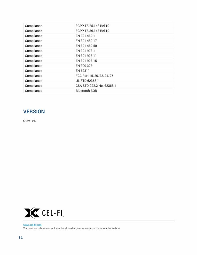
VERSION
QUM-V6
www.cel-fi.com Visit our website or contact your local Nextivity representative for more information.
Compliance 3GPP TS 25.143 Rel.10 Compliance 3GPP TS 36.143 Rel.10 Compliance EN 301 489-1 Compliance EN 301 489-17 Compliance EN 301 489-50 Compliance EN 301 908-1 Compliance EN 301 908-11 Compliance EN 301 908-15 Compliance EN 300 328 Compliance EN 62311 Compliance FCC Part 15, 20, 22, 24, 27 Compliance UL STD 62368-1 Compliance CSA STD C22.2 No. 62368-1 Compliance Bluetooth BQB

32
© 2018 Nextivity Inc. All rights reserved. All trademarks identified by ® or ™ are registered trademarks or trademarks, respectively, of Nextivity, Inc. This document is for planning purposes only and is not intended to modify or supplement any specifications or warranties relating to Nextivity products or services.