CEILING-MOUNTED MONORAIL - Rigid Lifelines · ®1-844-467-4443 | Rigid Lifelines Ceiling-Mounted...
42
ISO 9001:2008 Registered Manual 103-0075 CEILING-MOUNTED MONORAIL ANCHOR TRACK ™ SYSTEM Assembly and Operation Instruction Manual This manual is for various mounting types and plain and trussed track profiles.
-
Upload
vuongkhanh -
Category
Documents
-
view
216 -
download
0
Transcript of CEILING-MOUNTED MONORAIL - Rigid Lifelines · ®1-844-467-4443 | Rigid Lifelines Ceiling-Mounted...

ISO 9001:2008 Registered
Manual 103-0075
CEILING-MOUNTED MONORAILANCHOR TRACK™ SYSTEM
Assembly and Operation Instruction Manual
This manual is for various mounting types and plain and trussed track profiles.

Rigid Lifelines® Ceiling-Mounted Monorail Anchor Track™ System | 1-844-467-4443
RIGID LIFELINES’ CONDITIONS OF USE AND WARNING STATEMENT1. Read, understand, and follow the manual, assembly drawings, and warnings provided with your system before
beginning installation.
2. This manual, and any other instructions, must be provided to the users of this equipment. The user must understand the equipment’s proper use and limitations.
3. A fall event can result in serious injury or death. This equipment, when used properly, reduces the chances of those outcomes.
4. Always perform a hazard analysis before use that will identify impact hazards, swing hazards, or any other hazards that may exist. Address and correct all hazards before use.
5. Always have a written rescue plan that defines who will rescue a fallen worker, what equipment will be used, and optimum rescue response time. If the same system will be used for rescue, a minimum of a two-man system must be specified.
6. Follow all current requirements of ANSI Z359 (or CSA Z259 in Canada).
7. Each component and system must be employed and maintained in accordance with all OSHA and ANSI standards.
8. Per OSHA and ANSI (or CSA Z259 in Canada) requirements, designate a competent person who can fulfill obligations of all regulations.
9. Note the maximum number of users and weight capacities are listed on a label on the system. Exceeding the capacities listed on this label can result in serious injury or death.
10. Always check for overhead hazards, such as power lines, trees, overhead structures, or walls, before using or moving system.
11. Any component replacement, addition, or change to any portion of the system must be evaluated by a Qualified Person as defined by OSHA standards.
12. Never use this system for material handling.
13. Never use the system with scaffolding.
14. Never use the system alone without a monitor. Use the buddy system when using fall protection. The monitor, or “buddy,” does not need to be attached to the system, but just nearby supervising.
15. Consult with a qualified person for minimum fitness requirements for workers. Determination of minimum fitness levels of workers prior to use of system is by others.
16. For mobile systems—It is the responsibility of the user and their management’s Competent Person to determine that the system’s base is level, the masts are plumb, and that the entire, leveled system is stable before every use.
17. For moveable track systems—Always use the system in work spaces that allow you to move the system’s runway as close as possible to the center of the work area.
18. Before each use, inspect the system for bent, broken, cracked, or missing components.
19. A competent person must thoroughly inspect the system annually and after each fall event.
20. There should never be any type of loading past the end stops for any reason.
21. When connecting track sections, track splice and truss splice plates are required. For trussed track, splice joint centers must be within 48 inches of the hanger support centers unless otherwise specified. For plain track, splice track centers must be within 18 inches of the hanger support centers unless otherwise specified.
22. Systems with flush clamp hangers do not require sway bracing. However, all systems mounted to the ceiling must be laterally and longitudinally braced with bracing provided by others.

1-844-467-4443 | Rigid Lifelines® Ceiling-Mounted Monorail Anchor Track™ System
23. If supplied, all drive systems are chain driven, and as a result, will experience some backlash in the drive assembly. Although backlash cannot be fully eliminated, it can be reduced by tightening the drive chain. Torque limiters, if supplied, require special attention. Most drive issues result from improper torque limiter adjustment or installation.
24. It is the customer’s responsibility to confirm that the system and components will work in and are acceptable for their specific application and environment.
25. For foundation-mounted systems, bracing is not required for non-seismic applications. However, if any sway is perceived as undesirable, lateral bracing can be installed to the system by others. To achieve desired rigidity for a specific application, Rigid Lifelines® recommends consulting a professional engineer in your area to satisfy all codes and ordinances. For foundation-mounted systems, chemical anchor bolts supplied by others are required and must provide approximately 7000-pound pull-out force. More accurate pull-out forces are available upon request.
26. Engineering of any attachment points must be done by others.
27. Component appearances and dimensions shown are approximate and subject to change without notice. All catalog dimensions are developed using standard components for the spans and capacities. Substitution of optional trolleys or other components will affect certain dimensions.
28. All Rigid Lifelines’ Anchor Track™ Systems meet or exceed OSHA and ANSI requirements.
29. Never load the track at an angle greater than specified in the system’s user manual.
30. Never use the system with the attachment point below the D-Ring of the harness.
31. Only the following self-retracting lanyard (SRL) design specifications are acceptable for use on Rigid Lifelines’ Anchor Track Systems:
a ) 900-pound maximum average arresting force (MAAF)
b ) 4.5 feet-per-second lock up speed
c ) Disk or drum braking mechanism
d ) Wire rope SRL’s can be used for indoor or outdoor applications
e ) Fabric or web SRL’s can be used only for indoor applications
32. The following SRL’s absorbers are not acceptable: rip-stitch packs, shock packs, or stretchable energy.
33. Choose the shortest length SRL that will allow the workers to perform their job function. The shortest length SRL will reduce total fall distance by reducing “cable cinching” on the internal SRL pulley. Fabric lanyards stretch under load. The longer the lanyard, the longer the stretch.
34. Never use metallic cables or metallic SRL’s around electrical power sources.
35. Only an ANSI (or CSA in Canada) full-body harness is acceptable for use on Rigid Lifelines’ Anchor Track Systems.
36. Never use body belts on this system.
37. Never add additional carabiners, D-Rings, shackles, or connecting hardware to this system.
38. On Traveling Bridge Anchor Track Systems, always position the bridge(s) directly overhead of worker(s) at all times.
39. If a boom is provided, never apply a lateral load at the boom tip.
40. Never deviate from the above unless you have written permission and authorization from Rigid Lifelines.
RIGID LIFELINES’ CONDITIONS OF USE AND WARNING STATEMENT

1 Rigid Lifelines® Ceiling-Mounted Monorail Anchor Track™ System | 1-844-467-4443 1-844-467-4443 | Rigid Lifelines® Ceiling-Mounted Monorail Anchor Track™ System 2
Follow the Inspection Checklists in this manual: review the first checklist before each use and the second checklist for after a fall event and annual inspections.
NEVER EXCEED 30 DEGREES OFF-PLUMB (OFF-CENTER) LOADING.
SYSTEM APPLICATIONS The Ceiling-Mounted Monorail Anchor Track™ System is used for fall protection applications. This fall protection system is labeled with maximum number of users and maximum arresting force; follow all limitations as noted on system labels. Each user must attach to the Ceiling-Mounted Monorail track using a personal fall arrest system.
STANDARDS AND COMPLIANCEPlease refer to local, state, and federal (OSHA) requirements governing occupational safety for additional information regarding personal fall arrest systems. The Ceiling-Mounted Monorail Anchor Track System meets or exceeds the requirements set forth in OSHA 1910, OSHA 1926, and ANSI Z359.
REQUIRED TRAININGThe Ceiling-Mounted Monorail Anchor Track System is intended to be used by people who are trained in its correct application and use. It is the responsibility of the users and the users’ management to assure that they are familiar with these instructions and are trained in the correct use and care of this equipment. Authorized users must also be aware of the operating characteristics, application limits, and the consequences of improper use, which can result in serious injury or death.
Follow ANSI Z359.2 for instructions on how to set up a proper Fall Protection Program within your facility. ANSI Z359.2 Minimum Requirements for a Comprehensive Managed Fall Protection Program is available at: www.asse.org.
1 Rigid Lifelines® Ceiling-Mounted Monorail Anchor Track™ System | 1-844-467-4443 1-844-467-4443 | Rigid Lifelines® Ceiling-Mounted Monorail Anchor Track™ System 2
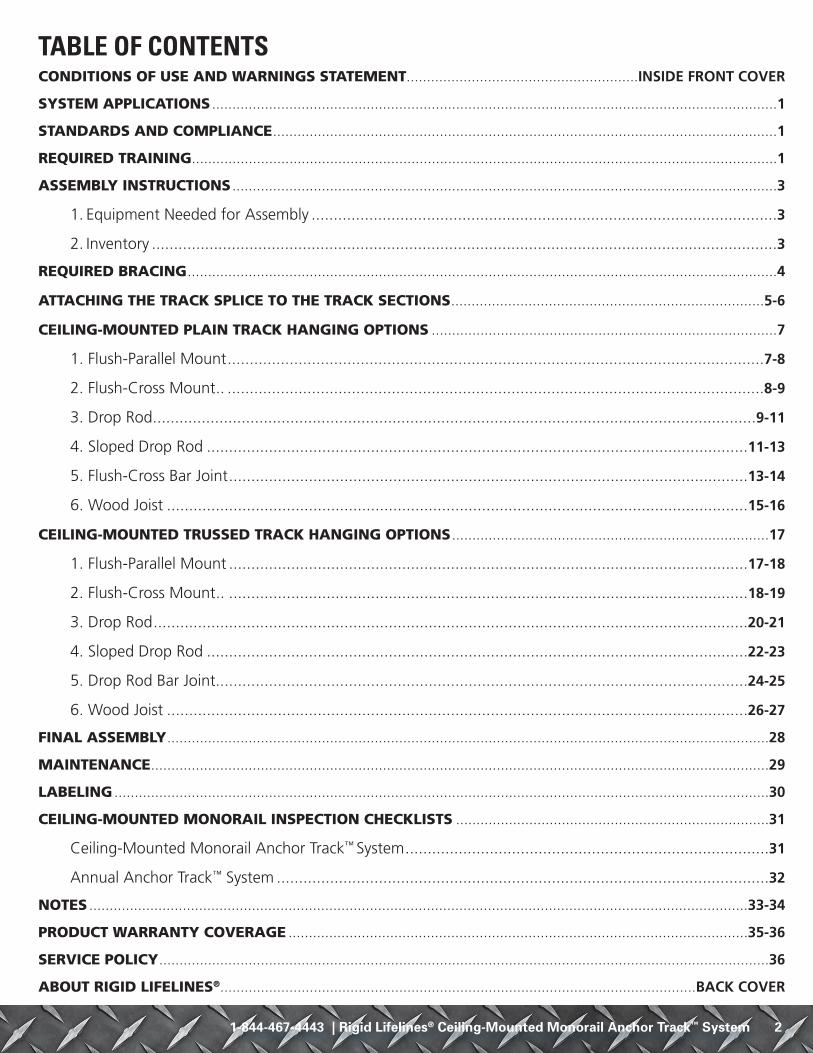
TABLE OF CONTENTSCONDITIONS OF USE AND WARNINGS STATEMENT .........................................................INSIDE FRONT COVER
SYSTEM APPLICATIONS ...........................................................................................................................................1
STANDARDS AND COMPLIANCE ............................................................................................................................1
REQUIRED TRAINING ................................................................................................................................................1
ASSEMBLY INSTRUCTIONS ......................................................................................................................................3
1. Equipment Needed for Assembly .........................................................................................................3
2. Inventory .............................................................................................................................................3
REQUIRED BRACING .................................................................................................................................................4
ATTACHING THE TRACK SPLICE TO THE TRACK SECTIONS .............................................................................5-6
CEILING-MOUNTED PLAIN TRACK HANGING OPTIONS .....................................................................................7
1. Flush-Parallel Mount .........................................................................................................................7-8
2. Flush-Cross Mount .. .........................................................................................................................8-9
3. Drop Rod ........................................................................................................................................9-11
4. Sloped Drop Rod ..........................................................................................................................11-13
5. Flush-Cross Bar Joint .....................................................................................................................13-14
6. Wood Joist ...................................................................................................................................15-16
CEILING-MOUNTED TRUSSED TRACK HANGING OPTIONS ..............................................................................17
1. Flush-Parallel Mount .....................................................................................................................17-18
2. Flush-Cross Mount .. .....................................................................................................................18-19
3. Drop Rod ......................................................................................................................................20-21
4. Sloped Drop Rod ..........................................................................................................................22-23
5. Drop Rod Bar Joint ........................................................................................................................24-25
6. Wood Joist ...................................................................................................................................26-27
FINAL ASSEMBLY ....................................................................................................................................................28
MAINTENANCE ........................................................................................................................................................29
LABELING .................................................................................................................................................................30
CEILING-MOUNTED MONORAIL INSPECTION CHECKLISTS .............................................................................31
Ceiling-Mounted Monorail Anchor Track™ System ..................................................................................31
Annual Anchor Track™ System ...............................................................................................................32
NOTES ..................................................................................................................................................................33-34
PRODUCT WARRANTY COVERAGE .................................................................................................................35-36
SERVICE POLICY ......................................................................................................................................................36
ABOUT RIGID LIFELINES® .....................................................................................................................BACK COVER

3 Rigid Lifelines® Ceiling-Mounted Monorail Anchor Track™ System | 1-844-467-4443 1-844-467-4443 | Rigid Lifelines® Ceiling-Mounted Monorail Anchor Track™ System 4
ASSEMBLY INSTRUCTIONS1. Equipment Needed for Assembly
a ) This manual
b ) Applicable safety equipment for workers’ use during assembly, such as hard hats, safety shoes, etc.
c ) Telescoping fork truck or crane (minimum lifting height: determined by installed system height; minimum capacity: 4,000 pounds)
d ) Man lift/cherry picker (minimum height: determined by installed system height)
e ) Measuring tape
f ) Torque wrench
g ) Lifting straps
h ) Two six-inch by six-inch (or larger) wood blocks
i ) Long carpenter’s level
j ) Wrench/Sockets sizes: 3/4 inch, 15/16 inch, and 1 1/8 inch
k ) A spacious, level area for assembly (e.g., parking lot)
l ) A way to mark hanger locations, such as a permanent marker
m ) FA-MT-ASSEMBLY SHEET 1 OF 2, hereafter referred to as Ceiling-Mounted Monorail Assembly Drawing, will be included as a separate document.
n ) FA-MT-ASSEMBLY SHEET 2 OF 2, hereafter referred to as Ceiling-Mounted Monorail Label Placement Drawing, will be included as a separate document.
o ) The Anchor Trolley™ User Instruction Manual (Manual 103-0054), which is packaged with the Anchor Trolley, will be included as a separate document
2. Inventorya ) Open all bundles and confirm that all components are accounted for: see Building Materials
Description located in the top right corner of the Ceiling-Mounted Monorail Assembly Drawing. Note that the quantity of components in an assembly are multiplied by the number of the assemblies.
b ) Check for damage to components that may have occurred during shipping.

3 Rigid Lifelines® Ceiling-Mounted Monorail Anchor Track™ System | 1-844-467-4443 1-844-467-4443 | Rigid Lifelines® Ceiling-Mounted Monorail Anchor Track™ System 4
REQUIRED BRACING
Refer to Figure 1 for Steps 1 Through 7
NOTE: Flush-mount applications do not require bracing.
1. Sway bracing is required for all ceiling-mounted monorail systems that use drop rods. Sway bracing resists lateral fall arrest forces, reduces lateral stresses on drop rods, and prevents system hardware from loosening and wear due to cyclic loading.
2. Sway bracing is required at each end of the system in both directions (laterally and longitudinally).
3. Intermediate bracing is required on one side of the monorail at each hanger assembly closest to the track splices (if required).
4. Rigid Lifelines is not liable for design of supporting structures or attachments of system hangers and/or bracing to supporting structures. However, Rigid Lifelines can provide the hangers for the bracing. All supporting structures must be designed by a qualified person using all applicable local, state, and national code requirements.
5. Support structures of structural steel must be designed, fabricated, and/or erected per requirements of “American Institute of Steel Construction” (AISC). Special attention must be given to the requirements for impact and deflection forces to maintain the integrity of the complete building structure and system. The qualified person is liable for the final design.
6. All bracing shown in Figure 1 is to be used as a guide only and should be considered as the minimum requirements for the ceiling-mounted monorail systems that use drop rods. Minimum pipe diameter is one inch for systems with drop rods. Systems with drop rods longer than 12 inches require special design attention by a qualified person.
7. Other bracing materials and designs may be acceptable if they are designed by a qualified person.
NOTE: A qualified person must determine proper brace tube strength before installation.
Figure 1
Monorail LengthSupport Centers Support CentersBracing
Bracing Brac
ing
BracingBrac
ing
Brac
ing
Brac
ing
Monorail
Top View
Support Centers Support CentersBracing Bracing
Drop Rods
Monorail
Support Structure
Pipe BracePipe Brace
Track Splice
Side View
Brac
ing
Brac
ing Drop
Rods
Bracing
Support Structure
Pipe Brace
End ViewMonorail bracing is provided by others. Typically, monorail bracing is at each end and at one side of the monorail at each hanger point.
Pipe brace is provided by others. Typically, pipe brace goes both ways at corners.
Support structure and pipe brace is provided by others. Typically, pipe brace goes both ways at corners.

5 Rigid Lifelines® Ceiling-Mounted Monorail Anchor Track™ System | 1-844-467-4443 1-844-467-4443 | Rigid Lifelines® Ceiling-Mounted Monorail Anchor Track™ System 6
ATTACHING THE TRACK SPLICE TO THE TRACK SECTIONSRefer to Figure 2 and Figure 3 for Steps 1 Through 9
1. Depending on the existing ceiling structure, span, and track series, track splices are required. If you purchased a system that requires a track splice, follow the steps below to attach the track splice to the track sections. If your system doesn’t require a track splice, proceed to Ceiling-Mounted Plain Track Hanger Options on page 7 or Ceiling-Mounted Trussed Track Hanger Options on page 17.
2. As per Figure 2, the track splice joint (B) comes assembled using a sleeve with a total of eight set screws threaded into the top and both sides.
3. As per Figure 2, slide the track splice joint (B) over the end of the first track section, then butt the second track section against the first. Center the track splice joint (B) over both track section ends.
4. As per Figure 2, hand tighten the top two center set screws to push the track sections against the base of the track splice joint (B) until both track section bottom surfaces are aligned. Adjust both sets of side set screws so that the track slots are aligned and there is a smooth transition from one track section to the other.
5. As per Figure 2, after you properly align the track sections (see Figure 3 on the following page), tighten the top set screws first before tightening the side set screws. Do not over-tighten set screws.
6. As per Figure 2, bolt the track splice plates (B1) to the top of the track sections on both sides using nuts (B3) and bolts (B2). Torque the nuts (B3) to 51 foot-pounds.
NOTE: The track splice plates (B1), nuts (B3), and bolts (B2) are only required for trussed track.
Figure 2
C
C
B1
B1
B
B2
B3
Item Description
C Track Sections
B Track Splice Joint
B1 Track Splice Plate
B2 1/2-inch Hex Head Bolt
B3 1/2-inch Hex Locknut

5 Rigid Lifelines® Ceiling-Mounted Monorail Anchor Track™ System | 1-844-467-4443 1-844-467-4443 | Rigid Lifelines® Ceiling-Mounted Monorail Anchor Track™ System 6
7. As per Figure 3, the track splice joint (B) must be properly aligned with the track sections.
Figure 3
8. If you ordered a multiple track system, repeat steps 2. through 7. to attach the remaining track splice(s) to the track sections.
9. Refer to Detail “B” below for an illustration of the properly attached track splice to the track sections.
Detail “B” (Track Splice to Track Sections)
B
B1
C
B2 B3
C
Item Description
C Track Sections
B Track Splice Joint
B1 Track Splice Plate
B2 1/2-inch Hex Head Bolt
B3 1/2-inch Hex Locknut
Top View of Incorrect Alignment Side View of Incorrect Alignment
Top View of Correct Alignment Side View of Correct Alignment

7 Rigid Lifelines® Ceiling-Mounted Monorail Anchor Track™ System | 1-844-467-4443 1-844-467-4443 | Rigid Lifelines® Ceiling-Mounted Monorail Anchor Track™ System 8
CEILING-MOUNTED PLAIN TRACK HANGING OPTIONS
1. Flush-Parallel MountRefer to Figure 4 for Steps A Through P
a ) Ensure that track splices (B in Ceiling-Mounted Monorail Assembly Drawing), if supplied, have been installed as per ATTACHING THE TRACK SPLICE TO THE TRACK SECTIONS on page 5.
b ) Using a measuring tape and a permanent marker, measure and mark one-foot in from each end of the track for standard overhang. Also measure and mark your support spacing requirements. These locations are where the hanger kits (A in Ceiling-Mounted Monorail Assembly Drawing) should be installed on the track.
NOTE: One-foot overhang is standard. Refer to your Final Fabrication Drawing for correct overhang lengths and support spacing for your specific system.
c ) As per Figure 4, slide all of the hanger brackets (7) onto the track so that the welded top plate on the hanger bracket (7) is facing up away from the track.
d ) As per Figure 4, slide an end hanger bracket (7) onto the marked spot on the track so that the welded top plate on the hanger bracket (7) is facing up away from the track.
e ) As per Figure 4, hand tighten the side set screw until snug to align the track against the side of the hanger bracket (7). Do not over tighten the set screw.
NOTE: The hanger bracket (7) comes with a set screw threaded into the side. It doesn’t matter which side. However, ensure that each hanger bracket (7) has the set screw threaded into the same side.
f ) As per Figure 4, insert bolts (3) through beam clips (2), clipped washers (5), and spacers (6) so that the clipped washers (5) are between the beam clips (2) and spacers (6).
NOTE: Clipped washers (5) may be required depending on the flange thickness. If clipped washers (5) are supplied, ensure that the flat edge of the clipped washers (5) face away from the center of the welded top plate of the hanger bracket (7). Spacers (6) are only required on systems using splices (B in Ceiling-Mounted Monorail Assembly Drawing).
g ) As per Figure 4, insert bolts (3) and attached components (2, 5, and 6) through the holes on top of the welded top plate of the hanger bracket (7) so that the beam clips (2), clipped washers (5), and spacers (6) are on top of the welded top plate of the hanger bracket (7).
h ) As per Figure 4, hand tighten the nuts (4) to the bolts (3).
Figure 4
Track
Ceiling Support Structure
Set Screw
3
256
4
7
Welded Top Plate
1
Item Description
1 Ceiling Support Structure
2 Beam Clip
3 5/8-inch Hex Bolt
4 5/8-inch Hex Locknut
5 Clipped Washer
6 Spacer
7 Hanger Bracket
NOTE: 700 Series Plain Track uses 3/4-inch hardware. Torque 3/4-inch hardware to 210 foot-pounds.

7 Rigid Lifelines® Ceiling-Mounted Monorail Anchor Track™ System | 1-844-467-4443 1-844-467-4443 | Rigid Lifelines® Ceiling-Mounted Monorail Anchor Track™ System 8
i ) Repeat steps d) through h) to attach another hanger bracket (7) to the marked spot on the other end of the track.
j ) Using a crane and lifting straps, lift the track to the existing ceiling support structure (1).
k ) Use a man lift or cherry picker to reach the track and ceiling support structure (1).
l ) As per Figure 4, position the track and attached components (2, 3, 5, and 6) so that the beam clips (2) are on each side of the ceiling support structure (1).
NOTE: Track splice joints (B in Ceiling-Mounted Monorail Assembly Drawing) must be within one foot from the center of a ceiling support structure (1).
m ) As per Figure 4, place the beam clips (2) so they are holding onto the bottom flange of the ceiling support structure (1). Adjust the beam clips (2) as needed by tightening or loosening the nuts (4) until the beam clips (2) sit properly on the bottom flange of the ceiling support structure (1). Securely snug the beam clips (2) to the bottom flange of the ceiling support structure (1).
n ) Repeat steps k) through m) to attach the track to the other end ceiling support structure (1).
o ) Now that the track is attached to the end ceiling support structures (1), repeat steps d) through h) and k) through m) to attach the track to the remaining ceiling support structures (1).
p ) After the track has been securely snugged to all ceiling support structures (1), ensure that all beam clips (2) are installed horizontally and level within plus or minus five degrees. Then torque all hanger kit 5/8-inch diameter locknuts (4) to 108 foot-pounds.
NOTE: Go to page 28 for final installation instructions.
2. Flush-Cross MountRefer to Figure 5 for Steps A Through P
a ) Ensure that track splices (B in Ceiling-Mounted Monorail Assembly Drawing), if supplied, have been installed as per ATTACHING THE TRACK SPLICE TO THE TRACK SECTIONS on page 5.
b ) Using a measuring tape and a permanent marker, measure and mark one-foot in from each end of the track for standard overhang. Also measure and mark your support spacing requirements. These locations are where the hanger kits (A in Ceiling-Mounted Monorail Assembly Drawing) should be installed on the track.
NOTE: One-foot overhang is standard. Refer to your Final Fabrication Drawing for correct overhang lengths and support spacing for your specific system.
c ) As per Figure 5, slide all of the hanger brackets (6) onto the track so that the welded top plate on the hanger bracket (6) is facing up away from the track.
d ) As per Figure 5, slide an end hanger bracket (6) onto the marked spot on the track so that the welded top plate on the hanger bracket (6) is facing up away from the track.
e ) As per Figure 5, hand tighten the side set screw until snug to align the track against the side of the hanger bracket (6). Do not over tighten the set screw.
NOTE: The hanger bracket (6) comes with a set screw threaded into the side. It doesn’t matter which side. However, ensure that each hanger bracket (6) has the set screw threaded into the same side.
f ) As per Figure 5, insert bolts (3) through beam clips (2) and clipped washers (5) so that the beam clips (2) are between the bolt head (3) and the clipped washer (5).
NOTE: Clipped washers (5) may be required depending on the flange thickness.

9 Rigid Lifelines® Ceiling-Mounted Monorail Anchor Track™ System | 1-844-467-4443 1-844-467-4443 | Rigid Lifelines® Ceiling-Mounted Monorail Anchor Track™ System 10
g ) As per Figure 5, insert bolts (3) and attached components (2 and 5) through the holes on top of the welded top plate of the hanger bracket (6) so that the beam clips (2) and clipped washers (5) are on top of the welded top plate of the hanger bracket (6).
h ) As per Figure 5, hand tighten the locknuts (4) to the bolts (3).
Figure 5
i ) Repeat steps d) through h) to attach another hanger bracket (6) to the marked spot on the other end of the track.
j ) Using a crane and lifting straps, lift the track to the existing ceiling support structure (1).
k ) Use a man lift or cherry picker to reach the track and ceiling support structure (1).
l ) As per Figure 5, position the track and attached components (2, 3, and 5) so that the beam clips (2) are on each side of the ceiling support structure (1).
NOTE: Track splice joints (B in Ceiling-Mounted Monorail Assembly Drawing) must be within one foot from the center of a ceiling support structure (1).
m ) As per Figure 5, place the beam clips (2) so they are holding onto the bottom flange of the ceiling support structure (1). Adjust the beam clips (2) as needed by tightening or loosening the locknuts (4) until the beam clips (2) sit properly on the bottom flange of the ceiling support structure (1). Securely snug the beam clips (2) to the bottom flange of the ceiling support structure (1).
n ) Repeat steps k) through m) to attach the track to the other end ceiling support structure (1).
o ) Now that the track is attached to the end ceiling support structures (1), repeat steps d) through h) and k) through m) to attach the track to the remaining ceiling support structures (1).
p ) After the track has been securely snugged to all ceiling support structures (1), ensure that all beam clips (2) are installed horizontally and level within plus or minus five degrees. Then torque all hanger kit 5/8-inch diameter locknuts (4) to 108 foot-pounds.
NOTE: Go to page 28 for final installation instructions.
3. Drop RodRefer to Figure 6 for Steps A Through X
a ) Ensure that track splices (B in Ceiling-Mounted Monorail Assembly Drawing), if supplied, have been installed as per ATTACHING THE TRACK SPLICE TO THE TRACK SECTIONS on page 5.
1
Set Screw
32
5
6
4Welded Top Plate
Item Description
1 Ceiling Support Structure
2 Beam Clip
3 5/8-inch Hex Bolt
4 5/8-inch Hex Locknut
5 Clipped Washer
6 Hanger Bracket
NOTE: 700 Series Plain Track uses 3/4-inch hardware. Torque 3/4-inch hardware to 210 foot-pounds.
NOTE: Torque all hanger kit 5/8-inch diameter locknuts (4) to 108 foot-pounds.

9 Rigid Lifelines® Ceiling-Mounted Monorail Anchor Track™ System | 1-844-467-4443 1-844-467-4443 | Rigid Lifelines® Ceiling-Mounted Monorail Anchor Track™ System 10
b ) Using a measuring tape and a permanent marker, measure and mark one-foot in from each end of the track for standard overhang. Also measure and mark your support spacing requirements. These locations are where the hanger kits (A in Ceiling-Mounted Monorail Assembly Drawing) should be installed on the track.
NOTE: One-foot overhang is standard. Refer to your Final Fabrication Drawing for correct overhang lengths and support spacing for your specific system.
c ) As per Figure 6, slide all of the hanger brackets (11) onto the track so that the welded top square on the hanger bracket (11) is facing up away from the track.
d ) As per Figure 6, slide an end hanger bracket (11) onto the marked spot on the track so that the welded top square on the hanger bracket (11) is facing up away from the track.
e ) As per Figure 6, hand tighten the side set screw until snug to align the track against the side of the hanger bracket (11). Do not over tighten the set screw.
NOTE: The hanger bracket (11) comes with a set screw threaded into the side. It doesn’t matter which side. However, ensure that each hanger bracket (11) has the set screw threaded into the same side.
f ) As per Figure 6, screw a nut (9) onto the bottom of the threaded drop rod (10) and adjust so that about three inches of the drop rod (10) are showing from the bottom of the nut (9).
g ) As per Figure 6, slide a lock washer (8) onto the threaded drop rod (10) so that the lock washer (8) is underneath the nut (9).
h ) As per Figure 6, insert the bottom of the threaded drop rod (10) into the hole on the welded top square of the hanger bracket (11) until the lock washer (8) is flush against the top of the welded top square of the hanger bracket (11) and the nut (9) is flush against the lock washer (8).
i ) As per Figure 6, screw a locknut (2) to the bottom of the threaded drop rod (10) and adjust so that an inch of drop rod (10) is showing underneath the locknut (2).
j ) As per Figure 6, screw a nut (9) onto the top of the threaded drop rod (10) so that about three inches of the drop rod (10) are showing from the top of the nut (9).
k ) As per Figure 6, slide a lock washer (8) onto the threaded drop rod (10) so that the lock washer (8) is on top of the nut (9).
l ) As per Figure 6, insert bolts (3) through beam clips (4) so that the beam clips (4) are underneath the bolt head (3).
m ) As per Figure 6, insert bolts (3) and attached beam clips (4) through the bottom side holes in the body forging (5) so that the beam clips (4) are on top of the body forging (5).
n ) As per Figure 6, hand tighten locknuts (7) and flat washers (6) to the bolts (3) so that the flat washers (6) are between the body forging (5) and locknuts (7).
o ) As per Figure 6, insert the top of the threaded drop rod (10) into the bottom middle hole of the body forging (5) until the lock washer (8) is flush against the bottom of the body forging (5) and the nut (9) is flush against the lock washer (8).
p ) As per Figure 6, screw a locknut (2) to the top of the threaded drop rod (10) and adjust so that an inch of drop rod (10) is showing above the locknut (2).
q ) Repeat steps d) through p) to attach another hanger bracket (11) to the marked spot on the other end of the track.

11 Rigid Lifelines® Ceiling-Mounted Monorail Anchor Track™ System | 1-844-467-4443 1-844-467-4443 | Rigid Lifelines® Ceiling-Mounted Monorail Anchor Track™ System 12
r ) Using a crane and lifting straps, lift the track to the existing ceiling support structure (1).
s ) Use a man lift or cherry picker to reach the track and ceiling support structure (1).
t ) As per Figure 6, position the track and attached components (2 through 11) so that the beam clips (4) are on each side of the ceiling support structure (1).
NOTE: Track splice joints (B in Ceiling-Mounted Monorail Assembly Drawing) must be within one foot from the center of a ceiling support structure (1).
u ) As per Figure 6, place the beam clips (4) so they are holding onto the bottom flange of the ceiling support structure (1). Adjust the beam clips (4) as needed by tightening or loosening the locknuts (7) until the beam clips (4) sit properly on the bottom flange of the ceiling support structure (1). Securely snug the beam clips (4) to the bottom flange of the ceiling support structure (1).
v ) Repeat steps r) through u) to attach the track to the other end ceiling support structure (1).
w ) Now that the track is attached to the end ceiling support structures (1 in Figure 6), repeat steps d) through p) and r) through u) to attach the track to the remaining ceiling support structures (1).
x ) After the track has been securely snugged to all ceiling support structures (1), ensure that all beam clips (4) are installed horizontally and level within plus or minus five degrees. Then torque all hanger kit 5/8-inch diameter locknuts (7) and drop rod 5/8-inch diameter locknuts (2) to 108 foot-pounds.
NOTE: Go to page 28 for final installation instructions.
Figure 6
4. Sloped Drop RodRefer to Figure 7 for Steps A Through W
a ) Ensure that track splices (B in Ceiling-Mounted Monorail Assembly Drawing), if supplied, have been installed as per ATTACHING THE TRACK SPLICE TO THE TRACK SECTIONS on page 5.
b ) Using a measuring tape and a permanent marker, measure and mark one-foot in from each end of the track for standard overhang. Also measure and mark your support spacing requirements. These locations are where the hanger kits (A in Building Materials Description) should be installed on the track.
NOTE: One-foot overhang is standard. Refer to your Final Fabrication Drawing for correct overhang lengths and support spacing for your specific system.
Item Description
1 Ceiling Support Structure
2 5/8-inch Hex Locknut
3 5/8-inch Hex Bolt
4 Beam Clip
5 Body Forging
6 5/8-inch Flat Washer
7 5/8-inch Hex Locknut
8 5/8-inch Lock Washer
9 5/8-inch Hex Nut
10 5/8-inch Drop Rod
11 Hanger BracketSet Screw
3 2
6
4
1
5
789
10
98
2
11
Welded Top Square
NOTE: 700 Series Plain Track uses 3/4-inch hardware. Torque 3/4-inch hardware to 210 foot-pounds.
NOTE: Torque all hanger kit and drop rod 5/8-inch diameter locknuts (2 and 7) to 108 foot-pounds.

11 Rigid Lifelines® Ceiling-Mounted Monorail Anchor Track™ System | 1-844-467-4443 1-844-467-4443 | Rigid Lifelines® Ceiling-Mounted Monorail Anchor Track™ System 12
c ) As per Figure 7, slide all of the hanger brackets (13) onto the track so that the welded top square on the hanger bracket (13) is facing up away from the track.
d ) As per Figure 7, slide an end hanger bracket (13) onto the marked spot on the track so that the welded top square on the hanger bracket (13) is facing up away from the track.
e ) As per Figure 7, hand tighten the side set screw until snug to align the track against the side of the hanger bracket (13). Do not over tighten the set screw.
NOTE: The hanger bracket (13) comes with a set screw threaded into the side. It doesn’t matter which side. However, ensure that each hanger bracket (13) has the set screw threaded into the same side.
f ) As per Figure 7, screw a nut (11) onto the bottom of the threaded drop rod (4) and adjust so that about three inches of the drop rod (4) are showing from the bottom of the nut (11).
g ) As per Figure 7, slide a lock washer (12) onto the threaded drop rod (4) so that the lock washer (12) is underneath the nut (11).
h ) As per Figure 7, insert the bottom of the threaded drop rod (4) into the hole on the welded top square of the hanger bracket (13) until the lock washer (12) is flush against the top of the welded top square of the hanger bracket (13) and the nut (11) is flush against the lock washer (12).
i ) As per Figure 7, screw a locknut (9) to the bottom of the threaded drop rod (4) and adjust so that an inch of drop rod (4) is showing underneath the locknut (9).
j ) As per Figure 7, insert the top of the drop rod (4) through the middle hole on the bottom of the beam clamp channel (2) so that three inches of drop rod (4) are showing.
k ) As per Figure 7, slide bevel washers (10) and a spherical washer (8) onto the threaded drop rod (4) so that the spherical washer (8) is on top of the bevel washers (10).
NOTE: The degree of slope determines how many bevel washers (10) are required.
l ) As per Figure 7, hand tighten a locknut (9) and a hex nut (11) onto the top of the drop rod (4) so that the locknut (9) is between the hex nut (11) and spherical washer (8).
m ) As per Figure 7, insert bolts (5) through flat washers (7) and the bottom slots in the beam clamp channel (2) so that the flat washers (7) are between the bolt heads (5) and the bottom of the beam clamp channel (2) and the bolt heads (5) are on the bottom of the beam clamp channel (2).
n ) As per Figure 7, slide beam clamp clips (3) onto the bolts (5) and hand tighten locknuts (6) to the bolts (5).
NOTE: Ensure that the beam clamp clip wedges are facing away from the center of the beam clamp channel (2).
o ) Repeat steps d) through n) to attach another hanger bracket (13 in Figure 7) to the marked spot on the other end of the track.
p ) Using a crane and lifting straps, lift the track to the existing ceiling support structure (1).
q ) Use a man lift or cherry picker to reach the track and ceiling support structure (1).
r ) As per Figure 7, position the track and attached components (2 through 13) so that the beam clamp clips (3) are on each side of the ceiling support structure (1).
NOTE: Track splice joints (B in Ceiling-Mounted Monorail Assembly Drawing) must be within one foot from the center of a ceiling support structure (1).

13 Rigid Lifelines® Ceiling-Mounted Monorail Anchor Track™ System | 1-844-467-4443 1-844-467-4443 | Rigid Lifelines® Ceiling-Mounted Monorail Anchor Track™ System 14
s ) As per Figure 7, place the beam clamp clips (3) so they are holding onto the bottom flange of the ceiling support structure (1). Adjust the beam clamp clips (3) as needed by tightening or loosening the locknuts (6) until the beam clamp clips (3) sit properly on the bottom flange of the ceiling support structure (1) and in the cutouts of beam clamp channel (2) and are an equal number of cutouts away from the center of the beam clamp channel (2). Ensure that the bolts (5) are as close as possible to the edge of bottom flange of the ceiling support structure (1).
t ) As per Figure 7, securely snug the locknuts (6) so that the beam clamp clips (3) are tight to the bottom flange of the ceiling support structure (1).
u ) Repeat steps q) through t) to attach the track to the other end ceiling support structure (1).
v ) Now that the track is attached to end ceiling support structures (1), repeat steps d) through n) and q) through t) to attach the track to the remaining ceiling support structures (1).
w ) After the track has been securely snugged to all ceiling support structures (1), ensure that all beam clamp clips (3) are installed horizontally and level within plus or minus five degrees. Then torque the top drop rod 5/8-inch diameter nuts (11) to 112 foot-pounds and all beam clamp and bottom drop rod 5/8-inch diameter locknuts (6 and 9) to 108 foot-pounds.
NOTE: Go to page 28 for final installation instructions.
Figure 7
5. Flush-Cross Bar JoistRefer to Figure 8 for Steps A Through O
a ) Ensure that track splices (B in Ceiling-Mounted Monorail Assembly Drawing), if supplied, have been installed as per ATTACHING THE TRACK SPLICE TO THE TRACK SECTIONS on page 5.
b ) Using a measuring tape and a permanent marker, measure and mark one-foot in from each end of the track for standard overhang. Also measure and mark your support spacing requirements. These locations are where the hanger kits (A in Ceiling-Mounted Monorail Assembly Drawing) should be installed on the track.
NOTE: One-foot overhang is standard. Refer to your Final Fabrication Drawing for correct overhang lengths and support spacing for your specific system.
2
Set Screw
1
3
45
6
7
89
10
11
1112
913
Welded Top Square
Beam Clamp Clip Wedge
Item Description
1 Ceiling Support Structure
2 Beam Clamp Channel
3 Beam Clamp Clip
4 5/8-inch Drop Rod
5 5/8-inch Hex Bolt
6 5/8-inch Hex Locknut
7 5/8-inch Flat Washer
8 Spherical Washer
9 5/8-inch Hex Locknut
10 5/8-inch Bevel Washer
11 5/8-inch Hex Nut
12 5/8-inch Lock Washer
13 Hanger Bracket
NOTE: 700 Series Plain Track uses 3/4-inch hardware. Torque 3/4-inch hardware to 210 foot-pounds.
NOTE: Torque all hanger kit and drop rod 5/8-inch diameter locknuts (6 and 9) to 108 foot-pounds.

13 Rigid Lifelines® Ceiling-Mounted Monorail Anchor Track™ System | 1-844-467-4443 1-844-467-4443 | Rigid Lifelines® Ceiling-Mounted Monorail Anchor Track™ System 14
c ) As per Figure 8, slide all of the hanger brackets (3) onto the track so that the welded top plate on the hanger bracket (3) is facing up away from the track.
d ) As per Figure 8, slide an end hanger bracket (3) onto the marked spot on the track so that the welded top square on the hanger bracket (3) is facing up away from the track.
e ) As per Figure 8, hand tighten the side set screw until snug to align the track against the side of the hanger bracket (3). Do not over tighten the set screw.
NOTE: The hanger bracket (3) comes with a set screw threaded into the side. It doesn’t matter which side. However, ensure that each hanger bracket (3) has the set screw threaded into the same side.
f ) Repeat steps d) and e) to attach another hanger bracket (3) to the marked spot on the other end of the track.
g ) Using a crane and lifting straps, lift the track to the existing ceiling support structure (1).
h ) Use a man lift or cherry picker to reach the track and ceiling support structure (1).
i ) As per Figure 8, position the track and attached hanger brackets (3) so that the hanger brackets (3) are directly underneath the ceiling support structure (1).
NOTE: Track splice joints (B in Ceiling-Mounted Monorail Assembly Drawing) must be within one foot from the center of a ceiling support structure (1).
j ) As per Figure 8, insert bolts (4) through bolt pads (2).
k ) As per Figure 8, insert the bolts (4) and attached bolt pads (2) through the bottom bar joist and holes on the welded top plate of the hanger bracket (3) so that the bolt head (4) and bolt pads (2) are on top of the bottom bar joint.
l ) As per Figure 8, securely snug locknuts (5) to the bolts (4).
m ) Repeat steps h) through l) to attach the track to the other end ceiling support structure (1).
n ) Now that the track is attached to the end ceiling support structures (1), repeat steps d) and e) and h) through l) to attach the track to the remaining ceiling support structures (1).
o ) After the track has been securely snugged to all ceiling support structures (1), torque all hanger kit locknuts (5) to 93 foot-pounds.
NOTE: Go to page 28 for final installation instructions.
Figure 8
12
4
35 Set Screw
Welded Top Plate
Item Description
1 Ceiling Support Structure
2 Bolt Pad
3 Hanger Bracket
4 5/8-inch Hex Bolt
5 5/8-inch Hex Locknut
NOTE: 700 Series Plain Track uses 3/4-inch hardware. Torque 3/4-inch hardware to 151 foot-pounds.

15 Rigid Lifelines® Ceiling-Mounted Monorail Anchor Track™ System | 1-844-467-4443 1-844-467-4443 | Rigid Lifelines® Ceiling-Mounted Monorail Anchor Track™ System 16
6. Wood JoistRefer to Figure 9 for Steps A Through AD
a ) Ensure that track splices (B in Ceiling-Mounted Monorail Assembly Drawing), if supplied, have been installed as per ATTACHING THE TRACK SPLICE TO THE TRACK SECTIONS on page 5.
b ) Using a measuring tape and a permanent marker, measure and mark one-foot in from each end of the track for standard overhang. Also measure and mark your support spacing requirements. These locations are where the hanger kits (A in Ceiling-Mounted Monorail Assembly Drawing) should be installed on the track.
NOTE: One-foot overhang is standard. Refer to your Final Fabrication Drawing for correct overhang lengths and support spacing for your specific system.
c ) As per Figure 9, slide all of the hanger brackets (10) onto the track so that the welded top square on the hanger bracket (10) is facing up away from the track.
d ) As per Figure 9, slide an end hanger bracket (10) onto the marked spot on the track so that the welded top square on the hanger bracket (10) is facing up away from the track.
e ) As per Figure 9, hand tighten the side set screw until snug to align the track against the side of the hanger bracket (10). Do not over tighten the set screw.
NOTE: The hanger bracket (10) comes with a set screw threaded into the side. It doesn’t matter which side. However, ensure that each hanger bracket (10) has the set screw threaded into the same side.
f ) As per Figure 9, screw a nut (8) onto the bottom of the threaded drop rod (9) and adjust so that about three inches of the drop rod (9) are showing from the bottom of the nut (8).
g ) As per Figure 9, slide a lock washer (7) onto the threaded drop rod (9) so that the lock washer (7) is underneath the nut (8).
h ) As per Figure 9, insert the bottom of the threaded drop rod (9) into the hole on the welded top square of the hanger bracket (10) until the lock washer (7) is flush against the top of the welded top square of the hanger bracket (10) and the nut (8) is flush against the lock washer (7).
i ) As per Figure 9, screw a locknut (4) to the bottom of the threaded drop rod (9) and adjust so that an inch of drop rod (9) is showing underneath the locknut (4).
j ) As per Figure 9, screw a nut (8) onto the top of the threaded drop rod (9) and adjust so that about three inches of the drop rod (9) are showing from the top of the nut (8).
k ) As per Figure 9, slide a lock washer (7) onto the threaded drop rod (10) so that the lock washer (7) is on top of the nut (8).
l ) Repeat steps d) through k) to attach another hanger bracket (10) to the marked spot on the other end of the track.
m ) Measure the distance between the hole centers on the wood bracket plate (2).
n ) Using a permanent marker, mark the hole center locations on the wood structure using the measurements from step m).
o ) Drill four holes into the wood structures for each hanger assembly.
p ) As per Figure 9, slide the top of the drop rod (9) through the bottom hole closest to the center of the wood bracket L plate (1) so that the lock washer (7) is flush against the bottom of the wood bracket L plate (1).

15 Rigid Lifelines® Ceiling-Mounted Monorail Anchor Track™ System | 1-844-467-4443 1-844-467-4443 | Rigid Lifelines® Ceiling-Mounted Monorail Anchor Track™ System 16
q ) As per Figure 9, screw a locknut (4) to the top of the drop rod (9).
r ) As per Figure 9, align the bottom hole of the wood bracket plate (2) with the bottom slot of the wood bracket L plate (1).
s ) As per Figure 9, insert a bolt (5) through the aligned holes in the wood bracket plates (1 and 2).
t ) As per Figure 9, hand tighten a flat washer (6) and a locknut (4) to the bolt (5) so that the flat washer (6) is between the bottom of the wood bracket L plate (1) and the locknut (4).
u ) Repeat steps p) through t) to attach the remaining wood bracket plates (1 and 2) to the top of the drop rods (9).
v ) Using a crane and lifting straps, lift the track to the existing wood structure.
w ) Use a man lift or cherry picker to reach the track and wood structure.
x ) As per Figure 9, position the track and attached components (1 through 10) so that the wood bracket plates (1 and 2) are on either side of the wood structure.
NOTE: Track splice joints (B in Ceiling-Mounted Monorail Assembly Drawing) must be within one foot from the center of where the wood bracket plates (1 and 2) connect to the wood structure.
y ) As per Figure 9, align the holes in the wood bracket plates (1 and 2) with the drilled holes in the wood structure.
z ) As per Figure 9, insert bolts (3) through the aligned holes in the wood bracket plates (1 and 2) and the wood structure.
aa ) As per Figure 9, securely snug locknuts (4) to the bolts (3).
ab ) Repeat steps v) through aa) to attach the track to the other end wood structure.
ac ) Now that the track is attached to the end wood structures, repeat steps d) through k), p) through t), and v) through aa) to attach the track to the remaining wood structures.
ad ) After the track has been securely snugged to all wood structures, torque all drop rod 5/8-inch diameter locknuts (4) to 93 foot-pounds.
NOTE: Go to page 28 for final installation instructions.
Figure 9
Item Description
1 Wood Bracket L Plate
2 Wood Bracket Plate
3 5/8-inch Hex Bolt
4 5/8-inch Hex Locknut
5 5/8-inch Hex Bolt
6 5/8-inch Flat Washer
7 5/8-inch Lock Washer
8 5/8-inch Hex Nut
9 5/8-inch Drop Rod
10 Hanger Bracket
Set Screw
4
10
Welded Top Square
Wood Structure1 2
34
5
464
78
9
8 7
NOTE: 700 Series Plain Track uses 3/4-inch hardware. Torque 3/4-inch hardware to 151 foot-pounds.

17 Rigid Lifelines® Ceiling-Mounted Monorail Anchor Track™ System | 1-844-467-4443 1-844-467-4443 | Rigid Lifelines® Ceiling-Mounted Monorail Anchor Track™ System 18
CEILING-MOUNTED TRUSSED TRACK HANGING OPTIONS1. Flush-Parallel Mount
Refer to Figure 10 for Steps A Through P
a ) Ensure that track splices (B in Ceiling-Mounted Monorail Assembly Drawing), if supplied, have been installed as per ATTACHING THE TRACK SPLICE TO THE TRACK SECTIONS on page 5.
b ) Using a measuring tape and a permanent marker, measure and mark one-foot six-inches in from each end of the track (9) for standard overhang. Also measure and mark your support spacing requirements. These locations are where the hanger kits (A in Ceiling-Mounted Monorail Assembly Drawing) should be installed on the track (9).
NOTE: One-foot six-inch overhang is standard. Refer to your Final Fabrication Drawing for correct overhang lengths and support spacing for your specific system.
c ) As per Figure 10, insert four bolts (2) through four beam clips (3) and clipped washers (4) so that the clipped washers (4) are underneath the beam clips (3).
d ) As per Figure 10, insert the bolts (2), beam clips (3), and clipped washers (4) through the truss clamp plate (5) so that the components (2, 3, and 4) are on top of the truss clamp plate (5).
NOTE: Clipped washers (4) may be required depending on the flange thickness. If clipped washers (4) are supplied, ensure that the flat edge of the clipped washers (4) face away from the center of the truss clamp plate (5).
e ) As per Figure 10, place the end of the truss clamp plate (5) and attached hardware (2, 3, and 4) on the marked spot on the end of the track (9) so that the bolts (2) hang down on both sides of the track (9). Ensure that the end of the truss clamp plate (5) is one-foot six-inches in from each end of the track (9) for standard overhang.
f ) As per Figure 10, place the hanger weldment (6) under the top truss of the track (9) so that the hanger weldment tubes are on both sides of the track (9) and resting underneath the truss clamp plate (5).
g ) As per Figure 10, insert the bolts (2) and attached components (3 and 4) through the holes on the hanger weldment (6).
h ) As per Figure 10, hand tighten flat washers (7) and locknuts (8) to the bolts (2) so that the flat washers (7) are between the bottom of the hanger weldment (6) and locknuts (8).
i ) Repeat steps c) through h) to attach another hanger kit (2 through 8) to the marked spot on the other end of the track (9).
j ) Using a crane and lifting straps, lift the track (9) to the existing ceiling support structure (1).
k ) Use a man lift or cherry picker to reach the track (9) and ceiling support structure (1).
l ) As per Figure 10, position the track (9) and attached components (2 through 8) so that the beam clips (3) are on each side of the ceiling support structure (1). Some loosening of the locknuts (8) may be required.
NOTE: Track splice joints (B in Ceiling-Mounted Monorail Assembly Drawing) must be within 48 inches from the center of a ceiling support structure (1).

17 Rigid Lifelines® Ceiling-Mounted Monorail Anchor Track™ System | 1-844-467-4443 1-844-467-4443 | Rigid Lifelines® Ceiling-Mounted Monorail Anchor Track™ System 18
m ) As per Figure 10, place the beam clips (3) so they are holding onto the bottom flange of the ceiling support structure (1). Adjust the beam clips (3) as needed by tightening or loosening the locknuts (8) until the beam clips (3) sit properly on the bottom flange of the ceiling support structure (1). Securely snug the beam clips (3) to the bottom flange of the ceiling support structure (1).
n ) Repeat steps k) through m) to attach the track (9) to the other end ceiling support structure (1).
o ) Now that the track (9) is attached to the end ceiling support structures (1), repeat steps c) through h) and k) through m) to attach the track (9) to the remaining ceiling support structures (1).
p ) After the track (9) has been securely snugged to all ceiling support structures (1), ensure that all beam clips (3) are installed horizontally and level within plus or minus five degrees. Then torque all hanger kit nuts (8) to 108 foot-pounds.
NOTE: Go to page 28 for final installation instructions.
Figure 10
2. Flush-Cross MountRefer to Figure 11 for Steps A Through N
a ) Ensure that track splices (B in Ceiling-Mounted Monorail Assembly Drawing), if supplied, have been installed as per ATTACHING THE TRACK SPLICE TO THE TRACK SECTIONS on page 5.
b ) Using a measuring tape and a permanent marker, measure and mark one-foot six-inches in from each end of the track (9) for standard overhang. Also measure and mark your support spacing requirements. These locations are where the hanger kits (A in Ceiling-Mounted Monorail Assembly Drawing) should be installed on the track (9).
NOTE: One-foot six-inch overhang is standard. Refer to your Final Fabrication Drawing for correct overhang lengths and support spacing for your specific system.
c ) As per Figure 11, insert four bolts (2) through four beam clips (3) and clipped washers (4) so that the clipped washers (4) are underneath the beam clips (3).
d ) As per Figure 11, insert the bolts (2), beam clips (3), and clipped washers (4) through the truss clamp plate (5) so that the components (2, 3, and 4) are on top of the truss clamp plate (5).
NOTE: Clipped washers (4) may be required depending on the flange thickness. If clipped washers (4) are supplied, ensure that the flat edge of the clipped washers (4) face away from the center of the truss clamp plate (5).
1
2
43
5
678
9
Hanger Weldment Tube
Item Description
1 Ceiling Support Structure
2 5/8-inch Hex Bolt
3 5/8-inch Beam Clip
4 5/8-inch Clipped Washer
5 Truss Clamp Plate
6 Hanger Weldment
7 5/8-inch Flat Washer
8 5/8-inch Hex Locknut
9 Track
NOTE: 700 Series track uses 3/4-inch hardware. Torque 3/4-inch hardware to 210 foot-pounds.
NOTE: Torque all hanger kit 5/8-inch diameter locknuts (8) to 108 foot-pounds.

19 Rigid Lifelines® Ceiling-Mounted Monorail Anchor Track™ System | 1-844-467-4443 1-844-467-4443 | Rigid Lifelines® Ceiling-Mounted Monorail Anchor Track™ System 20
e ) As per Figure 11, place the end of the truss clamp plate (5) and attached hardware (2, 3, and 4) on the marked spot on the end of the track (9) so that the bolts (2) hang down on both sides of the track (9). Ensure that the end of the truss clamp plate (5) is one-foot six-inches in from each end of the track (9) for standard overhang.
f ) As per Figure 11, hand tighten the angle truss clamps (8) to the bolts (2) using flat washers (6) and locknuts (7) so that the flat washers (6) are between the angle truss clamps (8) and locknuts (7). Ensure that the angle truss clamps (8) form inverted-L’s.
g ) Repeat steps c) through f) to attach another hanger kit (2 through 8) to the marked spot on the other end of the track (9).
h ) Using a crane and lifting straps, lift the track (9) to the existing ceiling support structure (1).
i ) Use a man lift or cherry picker to reach the track (9) and ceiling support structure (1).
j ) As per Figure 11, position the track (9) and attached components (2 through 8) so that the beam clips (3) are on each side of the ceiling support structure (1).
NOTE: Track splice joints (B in Ceiling-Mounted Monorail Assembly Drawing) must be within 48 inches from the center of a ceiling support structure (1).
k ) As per Figure 11, place the beam clips (3) so they are holding onto the bottom flange of the ceiling support structure (1). Adjust the beam clips (3) as needed by tightening or loosening the locknuts (7) until the beam clips (3) sit properly on the bottom flange of the ceiling support structure (1). Securely snug the beam clips (3) to the bottom flange of the ceiling support structure (1).
l ) Repeat steps i) through k) to attach the track (9) to the other end ceiling support structure (1).
m ) Now that the track (9) is attached to the end ceiling support structures (1), repeat steps c) through f) and i) through k) to attach the track (9) to the remaining ceiling support structures (1).
n ) After the track (9) has been securely snugged to all ceiling support structures (1), ensure that all beam clips (3) are installed horizontally and level within plus or minus five degrees. Then torque all hanger kit 5/8-inch diameter locknuts (7) to 108 foot-pounds.
NOTE: Go to page 28 for final installation instructions.
Figure 11
NOTE: 700 Series track uses 3/4-inch hardware. Torque 3/4-inch hardware to 210 foot-pounds.
1 2
43
5
78
9
6
Item Description
1 Ceiling Support Structure
2 5/8-inch Hex Bolt
3 5/8-inch Beam Clip
4 5/8-inch Clipped Washer
5 Truss Clamp Plate
6 5/8-inch Flat Washer
7 5/8-inch Locknut
8 Angle Truss Clamp
9 Track
NOTE: Torque all hanger kit 5/8-inch diameter locknuts (7) to 108 foot-pounds.

19 Rigid Lifelines® Ceiling-Mounted Monorail Anchor Track™ System | 1-844-467-4443 1-844-467-4443 | Rigid Lifelines® Ceiling-Mounted Monorail Anchor Track™ System 20
3. Drop RodRefer to Figure 12 for Steps A Through X
a ) Ensure that track splices (B in Ceiling-Mounted Monorail Assembly Drawing), if supplied, have been installed as per ATTACHING THE TRACK SPLICE TO THE TRACK SECTIONS on page 5.
b ) Using a measuring tape and a permanent marker, measure and mark one-foot six-inches in from each end of the track (15) for standard overhang. Also measure and mark your support spacing requirements. These locations are where the hanger kits (A in Ceiling-Mounted Monorail Assembly Drawing) should be installed on the track (15) .
NOTE: One-foot six-inch overhang is standard. Refer to your Final Fabrication Drawing for correct overhang lengths and support spacing for your specific system.
c ) As per Figure 12, insert two bolts (11) through two flat washers (12) and the bottom slots of the hanger truss bracket (10) so that the flat washers (12) are between the bolt heads and the bottom of the hanger truss bracket (10).
d ) As per Figure 12, place the hanger truss bracket (10) on the marked spot on the end of the track (15) so that the bolts (11) hang down on both sides of the track (15). Ensure that the end of the hanger truss bracket (10) is one-foot six-inches from the end of the track (15) for standard overhang.
e ) As per Figure 12, hand tighten the angle truss clamps (14) to the bolts (11) using flat washers (12) and locknuts (13) so that the flat washers (12) are between the angle truss clamps (14) and locknuts (13). Ensure that the angle truss clamps (14) form inverted-L’s.
f ) As per Figure 12, screw a nut (8) onto the bottom of the threaded drop rod (9) and adjust so that about three inches of the drop rod (9) are showing from the bottom of the nut (8).
g ) As per Figure 12, slide a lock washer (7) onto the threaded drop rod (9) so that the lock washer (7) is underneath the nut (8).
h ) As per Figure 12, insert the bottom of the threaded drop rod (9) into the top hole of the hanger truss bracket (10) until the lock washer (7) is flush against the top of the hanger truss bracket (10) and the nut (8) is flush against the lock washer (7).
i ) As per Figure 12, screw a locknut (6) to the bottom of the threaded drop rod (9) and adjust so that an inch of drop rod (9) is showing underneath the locknut (6).
j ) As per Figure 12, screw a nut (8) onto the top of the threaded drop rod (9) and adjust so that about three inches of the drop rod (9) are showing from the top of the nut (8).
k ) As per Figure 12, slide a lock washer (7) onto the threaded drop rod (9) so that the lock washer (7) is on top of the nut (8).
l ) As per Figure 12, insert two bolts (2) through beam clips (3) so that the beam clips (3) are underneath the bolt head (2).
m ) As per Figure 12, insert the bolts (2) and attached beam clips (3) through the bottom side holes in the body forging (4) so that the beam clips (3) are on top of the body forging (4).
n ) As per Figure 12, hand tighten locknuts (6) and flat washers (5) to the bolts (2) so that the flat washers (5) are between the body forging (4) and locknuts (6).
o ) As per Figure 12, insert the top of the threaded drop rod (9) into the bottom middle hole of the body forging (4) until the lock washer (7) is flush against the bottom of the body forging (4) and the nut (8) is flush against the lock washer (7).

21 Rigid Lifelines® Ceiling-Mounted Monorail Anchor Track™ System | 1-844-467-4443 1-844-467-4443 | Rigid Lifelines® Ceiling-Mounted Monorail Anchor Track™ System 22
p ) As per Figure 12, screw a locknut (6) to the top of the threaded drop rod (9) and adjust so that an inch of drop rod (9) is showing above the locknut (6).
q ) Repeat steps c) through p) to attach another hanger kit (2 through 14) to the marked spot on the other end of the track (15).
r ) Using a crane and lifting straps, lift the track (15) to the existing ceiling support structure (1).
s ) Use a man lift or cherry picker to reach the track (15) and ceiling support structure (1).
t ) As per Figure 12, position the track (15) and attached components (2 through 14) so that the beam clips (3) are on each side of the ceiling support structure (1).
NOTE: Track splice joints (B in Ceiling-Mounted Monorail Assembly Drawing) must be within 48 inches from the center of a ceiling support structure (1).
u ) As per Figure 12, place the beam clips (3) so they are holding onto the bottom flange of the ceiling support structure (1). Adjust the beam clips (3) as needed by tightening or loosening the locknuts (6) until the beam clips (3) sit properly on the bottom flange of the ceiling support structure (1). Securely snug the beam clips (3) to the bottom flange of the ceiling support structure (1).
v ) Repeat steps r) through u) to attach the track (15) to the other end ceiling support structure (1).
w ) Now that the track (15) is attached to the end ceiling support structures (1), repeat steps c) through p) and r) through u) to attach the track (15) to the remaining ceiling support structures (1).
x ) After the track (15) has been securely snugged to all ceiling support structures (1), ensure that all beam clips (3) are installed horizontally and level within plus or minus five degrees. Then torque all 5/8-inch locknuts (6) to 108 foot-pounds and all 1/2-inch locknuts (13) to 51 foot-pounds.
NOTE: Go to page 28 for final installation instructions.
Figure 12
Item Description
1 Ceiling Support Structure
2 5/8-inch Hex Bolt
3 5/8-inch Beam Clip
4 Body Forging
5 5/8-inch Flat Washer
6 5/8-inch Hex Locknut
7 5/8-inch Lock Washer
8 5/8-inch Hex Nut
9 Drop Rod
10 Hanger Truss Bracket
11 1/2-inch Hex Bolt
12 1/2-inch Flat Washer
13 1/2-inch Hex Locknut
14 Angle Truss Clamp
15 TrackNOTE: 700 Series Plain Track uses 3/4-inch hardware. Torque 3/4-inch hardware to 210 foot-pounds.
3
2
6
4
1
5
78
9
10
14
8
11
6
76
1213
1512
NOTE: Torque all hanger kit 5/8-inch diameter locknuts (6) to 108 foot-pounds.

21 Rigid Lifelines® Ceiling-Mounted Monorail Anchor Track™ System | 1-844-467-4443 1-844-467-4443 | Rigid Lifelines® Ceiling-Mounted Monorail Anchor Track™ System 22
4. Sloped Drop RodRefer to Figure 13 for Steps A Through W
a ) Ensure that track splices (B in Ceiling-Mounted Monorail Assembly Drawing), if supplied, have been installed as per ATTACHING THE TRACK SPLICE TO THE TRACK SECTIONS on page 5.
b ) Using a measuring tape and a permanent marker, measure and mark one-foot six-inches in from each end of the track (18) for standard overhang. Also measure and mark your support spacing requirements. These locations are where the hanger kits (A in Ceiling-Mounted Monorail Assembly Drawing) should be installed on the track (18).
NOTE: One-foot six-inch overhang is standard. Refer to your Final Fabrication Drawing for correct overhang lengths and support spacing for your specific system.
c ) As per Figure 13, insert two bolts (14) through two flat washers (16) and the bottom slots of the hanger truss bracket (13) so that the flat washers (16) are between the bolt heads and the bottom of the hanger truss bracket (13).
d ) As per Figure 13, place the hanger truss bracket (13) on the marked spot on the end of the track (18) so that the bolts (14) hang down on both sides of the track (18). Ensure that the end of the hanger truss bracket (13) is one-foot six-inches from the end of the track (18) for standard overhang.
e ) As per Figure 13, hand tighten the angle truss clamps (15) to the bolts (14) using flat washers (16) and locknuts (17) so that the flat washers (16) are between the angle truss clamps (15) and locknuts (17). Ensure that the angle truss clamps (15) form inverted-L’s.
f ) As per Figure 13, screw a nut (11) onto the bottom of the threaded drop rod (4) and adjust so that about three inches of the drop rod (4) are showing from the bottom of the nut (11).
g ) As per Figure 13, slide a lock washer (12) onto the threaded drop rod (4) so that the lock washer (12) is underneath the nut (11).
h ) As per Figure 13, insert the bottom of the threaded drop rod (4) into the top hole of the hanger truss bracket (13) until the lock washer (12) is flush against the top of the hanger truss bracket (13) and the nut (11) is flush against the lock washer (12).
i ) As per Figure 13, screw a locknut (9) to the bottom of the threaded drop rod (4) and adjust so that an inch of drop rod (4) is showing underneath the locknut (9).
j ) As per Figure 13, insert the top of the drop rod (4) through the middle hole on the bottom of the beam clamp channel (2) so that three inches of drop rod (4) are showing.
k ) As per Figure 13, slide bevel washers (10) and a spherical washer (8) onto the threaded drop rod (4) so that the spherical washer (8) is on top of the bevel washers (10).
NOTE: The degree of slope determines how many bevel washers (10) are required.
l ) As per Figure 13, hand tighten a locknut (9) and a hex nut (11) onto the top of the drop rod (4) so that the locknut (9) is between the hex nut (11) and spherical washer (8).
m ) As per Figure 13, insert bolts (5) through flat washers (7) and the bottom side holes in the beam clamp channel (2) so that the flat washers (7) are between the bolt heads (5) and the bottom of the beam clamp channel (2) and the bolt heads (5) are on the bottom of the beam clamp channel (2).
n ) As per Figure 13, slide beam clamp clips (3) onto the bolts (5) and hand tighten locknuts (6) to the bolts (5).
NOTE: Ensure that the beam clamp clip wedges are facing away from the center of the beam clamp channel (2).

23 Rigid Lifelines® Ceiling-Mounted Monorail Anchor Track™ System | 1-844-467-4443 1-844-467-4443 | Rigid Lifelines® Ceiling-Mounted Monorail Anchor Track™ System 24
o ) Repeat steps c) through n) to attach another hanger truss bracket (13) to the marked spot on the other end of the track (18).
p ) Using a crane and lifting straps, lift the track (18) to the existing ceiling support structure (1).
q ) Use a man lift or cherry picker to reach the track (18) and ceiling support structure (1).
r ) As per Figure 13, position the track (18) and attached components (2 through 17) so that the beam clamp clips (3) are on each side of the ceiling support structure (1).
NOTE: Track splice joints (B in Ceiling-Mounted Monorail Assembly Drawing) must be within 48 inches from the center of a ceiling support structure (1)
s ) As per Figure 13, place the beam clamp clips (3) so they are holding onto the bottom flange of the ceiling support structure (1). Adjust the beam clamp clips (3) as needed by tightening or loosening the locknuts (6) until the beam clamp clips (3) sit properly on the bottom flange of the ceiling support structure (1) and in the cutouts of beam clamp channel (2) and are an equal number of cutouts away from the center of the beam clamp channel (2). Ensure that the bolts (5) are as close as possible to the edge of bottom flange of the ceiling support structure (1).
t ) As per Figure 13, securely snug the locknuts (6) so that the beam clamp clips (3) are tight to the bottom flange of the ceiling support structure (1).
u ) Repeat steps q) through t) to attach the track (18) to the other end ceiling support structure (1).
v ) Now that the track (18) is attached to end ceiling support structures (1), repeat steps c) through n) and q) through t) to attach the track (18) to the remaining ceiling support structures (1).
w ) After the track (18) has been securely snugged to all ceiling support structures (1), ensure that all beam clamp clips (3) are installed horizontally and level within plus or minus five degrees. Then torque the top drop rod 5/8-inch diameter nuts (11) to 112 foot-pounds, beam clamp and bottom drop rod 5/8-inch diameter locknuts (6 and 9) to 108 foot-pounds, and all hanger kit 1/2-inch diameter locknuts (17) to 51 foot-pounds.
NOTE: Go to page 28 for final installation instructions.
Figure 13
Item Description
15 Angle Truss Clamp
16 1/2-inch Flat Washer
17 1/2-inch Hex Locknut
18 Track
NOTE: 700 Series Plain Track uses 3/4-inch hardware. Torque 3/4-inch hardware to 210 foot-pounds.
Item Description
1 Ceiling Support Structure
2 Beam Clamp Channel
3 Beam Clamp Clip
4 5/8-inch Drop Rod
5 5/8-inch Hex Bolt
6 5/8-inch Hex Locknut
7 5/8-inch Flat Washer
8 Spherical Washer
9 5/8-inch Hex Locknut
10 5/8-inch Bevel Washer
11 5/8-inch Hex Nut
12 5/8-inch Lock Washer
13 Hanger Truss Bracket
14 1/2-inch Hex Bolt
2
1
3
45
6
7
89
10
11
1112
9
Beam Clamp Clip Wedge
13
1415 16
1718
16
NOTE: Torque all beam clamp and bottom drop rod 5/8-inch diameter locknuts (6 and 9) to 108 foot-pounds.

23 Rigid Lifelines® Ceiling-Mounted Monorail Anchor Track™ System | 1-844-467-4443 1-844-467-4443 | Rigid Lifelines® Ceiling-Mounted Monorail Anchor Track™ System 24
5. Drop Rod Bar JoistRefer to Figure 14 for Steps A Through V
a ) Ensure that track splices (B in Ceiling-Mounted Monorail Assembly Drawing), if supplied, have been installed as per ATTACHING THE TRACK SPLICE TO THE TRACK SECTIONS on page 5.
b ) Using a measuring tape and a permanent marker, measure and mark one-foot six-inches in from each end of the track (12) for standard overhang. Also measure and mark your support spacing requirements. These locations are where the hanger kits (A in Ceiling-Mounted Monorail Assembly Drawing) should be installed on the track (12).
NOTE: One-foot six-inch overhang is standard. Refer to your Final Fabrication Drawing for correct overhang lengths and support spacing for your specific system.
c ) As per Figure 14, insert two bolts (8) through two flat washers (10) and the bottom slots of the hanger truss bracket (7) so that the flat washers (10) are between the bolt heads and the bottom of the hanger truss bracket (7).
d ) As per Figure 14, place the hanger truss bracket (7) on the marked spot on the end of the track (12) so that the bolts (8) hang down on both sides of the track (12). Ensure that the end of the hanger truss bracket (7) is one-foot six-inches from the end of the track (12) for standard overhang.
e ) As per Figure 14, hand tighten the angle truss clamps (9) to the bolts (8) using flat washers (10) and locknuts (11) so that the flat washers (10) are between the angle truss clamps (9) and locknuts (11). Ensure that the angle truss clamps (9) form inverted-L’s.
f ) As per Figure 14, screw a nut (6) onto the bottom of the threaded drop rod (2) and adjust so that about three inches of the drop rod (2) are showing from the bottom of the nut (6).
g ) As per Figure 14, slide a lock washer (5) onto the threaded drop rod (2) so that the lock washer (5) is underneath the nut (6).
h ) As per Figure 14, insert the bottom of the threaded drop rod (2) into the top hole of the hanger truss bracket (7) until the lock washer (5) is flush against the top of the hanger truss bracket (7) and the nut (6) is flush against the lock washer (5).
i ) As per Figure 14, screw a locknut (3) to the bottom of the threaded drop rod (2) and adjust so that an inch of drop rod (2) is showing underneath the locknut (3).
j ) As per Figure 14, screw a nut (6) onto the top of the threaded drop rod (2) and adjust so that about three inches of the drop rod (2) are showing from the top of the nut (6).
k ) As per Figure 14, slide a lock washer (5) onto the threaded drop rod (2) so that the lock washer (5) is on top of the nut (6).
l ) As per Figure 14, slide a bolt pad (4) onto the threaded drop rod (2) so that the bolt pad (4) is on top of the lock washer (5).
m ) Repeat steps c) through l) to attach another hanger truss bracket (7) to the marked spot on the other end of the track (12).
n ) Using a crane and lifting straps, lift the track (12) to the existing ceiling support structure (1).
o ) Use a man lift or cherry picker to reach the track (12) and ceiling support structure (1).
p ) As per Figure 14, position the track (12) and attached hanger truss brackets (7) so that the hanger truss brackets (7) are directly underneath the ceiling support structure (1).

25 Rigid Lifelines® Ceiling-Mounted Monorail Anchor Track™ System | 1-844-467-4443 1-844-467-4443 | Rigid Lifelines® Ceiling-Mounted Monorail Anchor Track™ System 26
NOTE: Track splice joints (B in Ceiling-Mounted Monorail Assembly Drawing) must be within 48 inches from the center of a ceiling support structure (1).
q ) As per Figure 14, insert the top of the drop rod (2) through the bottom of the ceiling support structure (1) so that the attached components (4, 5, and 6) are underneath the ceiling support structure (1).
r ) As per Figure 14, slide another bolt pad (4) onto the top of the threaded drop rod (2) and adjust so that about an inch of drop rod (2) is showing from the top of the bolt pad (4).
s ) As per Figure 14, screw a locknut (3) to the top of the threaded drop rod (2) and adjust so that the bolt pad (4) is underneath the locknut (3).
t ) Repeat steps o) through s) to attach the track (12) to the other end ceiling support structure (1).
u ) Now that the track (12) is attached to the end ceiling support structures (1), repeat steps c) through l) and o) through s) to attach the track (12) to the remaining ceiling support structures (1).
v ) After the track (12) has been securely snugged to all ceiling support structures (1), torque all 5/8-inch locknuts (3) to 93 foot-pounds and all 1/2-inch locknuts (11) to 51 foot-pounds.
NOTE: Drop rod bar joist hanger assemblies can be used with plain track and plain track hanger kits. Refer to “3. Drop Rod” on pages 9-11 to attach the plain track and plain track hanger kits to the drop rod bar joint hanger assemblies.
NOTE: Go to page 28 for final installation instructions.
Figure 14
7
11
8
10
23
4
14 5
6
6
5
3
9
12
10
Item Description
1 Ceiling Support Structure
2 Drop Rod
3 5/8-inch Hex Locknut
4 Bolt Pad
5 5/8-inch Lock Washer
6 5/8-inch Hex Nut
7 Hanger Truss Bracket
8 1/2-inch Hex Bolt
9 Angle Truss Clamp
10 1/2-inch Flat Washer
11 1/2-inch Hex Locknut
12 Track
NOTE: 700 Series Plain Track uses 3/4-inch hardware. Torque 3/4-inch hardware to 151 foot-pounds.

25 Rigid Lifelines® Ceiling-Mounted Monorail Anchor Track™ System | 1-844-467-4443 1-844-467-4443 | Rigid Lifelines® Ceiling-Mounted Monorail Anchor Track™ System 26
6. Wood JoistRefer to Figure 15 for Steps A Through AD
a ) Ensure that track splices (B in Ceiling-Mounted Monorail Assembly Drawing), if supplied, have been installed as per ATTACHING THE TRACK SPLICE TO THE TRACK SECTIONS on page 5.
b ) Using a measuring tape and a permanent marker, measure and mark one-foot six-inches in from each end of the track for standard overhang. Also measure and mark your support spacing requirements. These locations are where the hanger kits (A in Ceiling-Mounted Monorail Assembly Drawing) should be installed on the track.
NOTE: One-foot six-inch overhang is standard. Refer to your Final Fabrication Drawing for correct overhang lengths and support spacing for your specific system.
c ) As per Figure 15, insert two bolts (11) through two flat washers (13) and the bottom slots of the hanger truss bracket (10) so that the flat washers (13) are between the bolt heads and the bottom of the hanger truss bracket (10).
d ) As per Figure 15, place the hanger truss bracket (10) on the marked spot on the end of the track so that the bolts (11) hang down on both sides of the track. Ensure that the end of the hanger truss bracket (10) is one-foot six-inches from the end of the track for standard overhang.
e ) As per Figure 15, hand tighten the angle truss clamps (12) to the bolts (11) using flat washers (13) and locknuts (14) so that the flat washers (13) are between the angle truss clamps (12) and locknuts (14). Ensure that the angle truss clamps (12) form inverted-L’s.
f ) As per Figure 15, screw a nut (8) onto the bottom of the threaded drop rod (9) so that about three inches of the drop rod (9) are showing from the bottom of the nut (8).
g ) As per Figure 15, slide a lock washer (7) onto the threaded drop rod (9) so that the lock washer (7) is underneath the nut (8).
h ) As per Figure 15, insert the bottom of the threaded drop rod (9) into the top hole of the hanger truss bracket (10) until the lock washer (7) is flush against the top of the hanger truss bracket (10) and the nut (8) is flush against the lock washer (7).
i ) As per Figure 15, screw a locknut (4) to the bottom of the threaded drop rod (9) and adjust so that an inch of drop rod (9) is showing underneath the locknut (4).
j ) As per Figure 15, screw a nut (8) onto the top of the threaded drop rod (9) and adjust so that about three inches of the drop rod (9) are showing from the top of the nut (6).
k ) As per Figure 15, slide a lock washer (7) onto the threaded drop rod (9) so that the lock washer (7) is on top of the nut (8).
l ) Repeat steps c) through k) to attach another hanger truss bracket (10) to the marked spot on the other end of the track.
m ) Measure the distance between the hole centers on the wood bracket plate (2).
n ) Using a permanent marker, mark the hole center locations on the wood structure using the measurements from step m).
o ) Drill four holes into the wood structures for each hanger assembly.
p ) As per Figure 15, slide the top of the drop rod (9) through the bottom hole closest to the center of the wood bracket L plate (1) so that the lock washer (7) is flush against the bottom of the wood bracket L plate (1).

27 Rigid Lifelines® Ceiling-Mounted Monorail Anchor Track™ System | 1-844-467-4443 1-844-467-4443 | Rigid Lifelines® Ceiling-Mounted Monorail Anchor Track™ System 28
q ) As per Figure 15, screw a locknut (4) to the top of the drop rod (9).
r ) As per Figure 15, align the bottom hole of the wood bracket plate (2) with the bottom side hole of the wood bracket L plate (1).
s ) As per Figure 15, insert a bolt (5) through the aligned holes in the wood bracket plates (1 and 2).
t ) As per Figure 15, hand tighten a flat washer (6) and a locknut (4) to the bolt (5) so that the flat washer (6) is between the bottom of the wood bracket L plate (1) and the locknut (4).
u ) Repeat steps p) through t) to attach the remaining wood bracket plates (1 and 2) to the top of the drop rods (9).
v ) Using a crane and lifting straps, lift the track to the existing wood structure.
w ) Use a man lift or cherry picker to reach the track and wood structure.
x ) As per Figure 15, position the track and attached components (1 through 11) so that the wood bracket plates (1 and 2) are on either side of the wood structure.
NOTE: Track splice joints (B in Ceiling-Mounted Monorail Assembly Drawing) must be within 48 inches from the center of where the wood bracket plates (1 and 2) connect to the wood structure.
y ) As per Figure 15, align the holes in the wood bracket plates (1 and 2) with the drilled holes in the wood structure.
z ) As per Figure 15, insert bolts (3) through the aligned holes in the wood bracket plates (1 and 2) and the wood structure.
aa ) As per Figure 15, securely snug locknuts (4) to the bolts (3).
ab ) Repeat steps w) through aa) to attach the track to the other end wood structure.
ac ) Now that the track is attached to the end wood structures, repeat steps c) through k), p) through t), and w) through aa) to attach the track to the remaining wood structures.
ad ) After the track has been securely snugged to all wood structures, torque all 5/8-inch locknuts (4) to 93 foot-pounds and all 1/2-inch locknuts (14) to 51 foot-pounds.
NOTE: Go to page 28 for final installation instructions.
Figure 15Item Description
1 Wood Bracket L Plate
2 Wood Bracket Plate
3 5/8-inch Hex Bolt
4 5/8-inch Hex Locknut
5 5/8-inch Hex Bolt
6 5/8-inch Flat Washer
7 5/8-inch Lock Washer
8 5/8-inch Hex Nut
9 5/8-inch Drop Rod
10 Hanger Truss Bracket
11 1/2-inch Hex Bolt
12 Angle Truss Clamp
Item Description
13 1/2-inch Flat Washer
14 1/2-inch Hex Locknut
NOTE: 700 Series Plain Track uses 3/4-inch hardware. Torque 3/4-inch hardware to 151 foot-pounds.
4
Wood Structure1 2
34
54
64
78
9
8 7
1110
121314
13

27 Rigid Lifelines® Ceiling-Mounted Monorail Anchor Track™ System | 1-844-467-4443 1-844-467-4443 | Rigid Lifelines® Ceiling-Mounted Monorail Anchor Track™ System 28
FINAL ASSEMBLYRefer to Ceiling-Mounted Monorail Assembly Drawing for Steps 1 Through 7
1. Ensure that the track (C in Building Materials Description) is secured properly to the ceiling support structure (1 in Building Materials Description).
2. Confirm that all of the system’s nuts are torqued to the required specifications below prior to removing support rigging (your telescoping fork truck or crane) from any component.
Bolt Diameter Hex Nut Torque Minimum Hex Locknut Torque
1/2 inch 78 foot-pounds 51 foot-pounds
5/8 inch 154 foot-pounds 93 foot-pounds
3/4 inch 257 foot-pounds 151 foot-pounds
7/8 inch 341 foot-pounds 224 foot-pounds
1 inch 514 foot-pounds 325 foot-pounds
NOTE: The hanger kit 5/8-inch nuts (A4 and AA6) should be torqued to 108 foot-pounds and hanger kit 1/2-inch nuts should be torqued to 51 foot-pounds.
3. As per Detail “C,” insert your Anchor Trolley™ (C1) into the track (C). For a multiple track system, install one Anchor Trolley per track.
4. As per Detail “C,” install the track’s end stops by inserting the bolts (C3) through the holes at both ends of the track (C) and through the rubber sleeves (C5).
Detail “C” (Trolley[s] and End Stops to Track)
5. Attach and torque the end stop nuts (C4) until snug against the track.
6. For multiple track systems, repeat steps 1. through 5. to insert the remaining Anchor Trolleys (C1) into the remaining tracks (C).
7. This system must be used with an ANSI-rated self-retracting lanyard (SRL). Connect your SRL and retrieval tagline in accordance with the manufacturer’s specifications and your training.
Item Description
C Track
C1 Swiveling Connector Anchor Trolley
C3 End Stop Bolt
C4 1/2-inch Hex Locknut
C5 End Stop Rubber Sleeve
NOTE: The 1/2-inch hex locknuts (C4) should be torqued until snug against the track. Be careful not to damage the track in any way.
C5
C1
C
C3 C4

29 Rigid Lifelines® Ceiling-Mounted Monorail Anchor Track™ System | 1-844-467-4443 1-844-467-4443 | Rigid Lifelines® Ceiling-Mounted Monorail Anchor Track™ System 30
MAINTENANCE 1. Visually inspect the system before each use and fully inspect the system after a fall event and annually.
Refer to the INSPECTION CHECKLISTS in the next section of this manual for checklists for Ceiling-Mounted Monorail Anchor Track™ System and Annual Anchor Track™ System.
2. If the system fails ANY inspection point on any of the inspection checklists, immediately remove the system from service and call Rigid Lifelines® at 844-467-4443 for instructions.
3. During the first month after a new installation, a weekly inspection of the system should be performed using the Annual Anchor Track™ System Inspection Checklist. It is important to note that every system application and use will be different, meaning some conditions of use will require more frequent inspection. Examples of such conditions include two or three shift operations or working with or near corrosive chemicals or elements.
4. Refer to the Anchor Trolley™ User Instruction Manual (Manual 103-0054), which comes packaged with the Anchor Trolley, for its trolley inspection checklists.
5. Download and print additional blank inspection checklists from the literature tab at RigidLifelines.com.
This system must be used with an ANSI-rated self-retracting lanyard (SRL).
If the system is used outdoors, it is highly recommended that a steel cable SRL with heavy-duty housing be used for improved durability against UV radiation and moisture.
A web strap ANSI-rated SRL may be acceptable for use as long as a Competent Person has evaluated the situation and determined that there are no factors present that can have an immediate negative impact on the integrity of the SRL’s webbing material AND that the Competent Person inspects the condition of the SRL’s webbing and housing prior to each use.
Completely retracting the SRL after each use (e.g., using a retrieval tagline) is essential: otherwise, the SRL’s internal spring remains under tension, and it quickly loses its ability to properly arrest a freefall.
Retrieval taglines must never be used as an anchorage; doing so could result in serious injury or death.

29 Rigid Lifelines® Ceiling-Mounted Monorail Anchor Track™ System | 1-844-467-4443 1-844-467-4443 | Rigid Lifelines® Ceiling-Mounted Monorail Anchor Track™ System 30
LABELINGThe letters correspond to the letters on the Ceiling-Mounted Monorail Label Placement Drawing. All labeling must be legible and attached to the system. For replacement labels, contact Rigid Lifelines®.
Notes on Label Placement Drawing
• Label 53-0047 “A” should be placed on both ends of the lower section of trussed track on both sides of each track section.
• Label 53-0359 “B” should be centered on the lower section of trussed track on both sides of each track section and is P/N 53-0535 for one person systems, 53-0536 for two person systems, and 53-0359 for three to eight person systems, along with 53-0413 through 53-0418 respectively. Labels P/N 53-0413 through 53-0418 are the capacity numbers three through eight for the Anchor Track Label and should be placed to the right of the line following “Rigid Lifelines.”
• Label 53-0023 “C” should be placed to the left of label “B” on the lower section of trussed track on both sides.
“C”
P/N 53-0023
P/N 53-0023
“A”
P/N 53-0047
TO PREVENT TROLLEY OR END TRUCK, IF SUPPLIED, FROM RUNNING OUT OF THETRACK, DO NOT OPERATE SYSTEM WITHOUT END STOP BOLTS SECURED ON EACH END OF RUNWAY AND BRIDGE, IF SUPPLIED.
DO NOT IMPACT END STOPS AT HIGH SPEEDDO NOT USE END STOPS FOR REPETITIVE BRIDGE IMPACTS, IF BRIDGE IS SUPPLIEDDO NOT SKEW BRIDGE, IF SUPPLIED, IN RUNWAYS
P/N 53-0047
P/N 53-0359
“B”
RIGID LIFELINES’ LABEL PLACEMENT DISCLAIMERIf system is shipped unpainted or without properly secured labels, proper label placement is the sole responsibility
of the end user. Follow the Label Placement Drawing shipped with this user manual to place labels correctly. Rigid Lifelines cannot be held liable for any damage or injury resulting from omitted or improper label placement.

31 Rigid Lifelines® Ceiling-Mounted Monorail Anchor Track™ System | 1-844-467-4443 1-844-467-4443 | Rigid Lifelines® Ceiling-Mounted Monorail Anchor Track™ System 32
CEILING-MOUNTED MONORAIL ANCHOR TRACK™ SYSTEM INSPECTION CHECKLISTBefore Each UseInspector Name: __________________________________________________
Date:_____________________________________________________________
System Number: __________________________________________________
Model: ___________________________________________________________
Inspection Result (3)
INSPECTION POINTS PASS FAIL1. Test the swiveling connector(s) on each trolley to verify that each trolley rotates and swivels freely.
2. Verify that the trolley(s) can easily and smoothly roll the full length of the runway track(s).
3. Check all system welds for cracks.
4. Check system components for corrosion.
5. Check system components for bent or damaged areas.
6. Check support structure for stability.
7. Visually check all bolted assemblies for proper connections and properly secured bolts and nuts.
©2016. All Rights Reserved. All specifications and product designs subject to change without prior notice.

31 Rigid Lifelines® Ceiling-Mounted Monorail Anchor Track™ System | 1-844-467-4443 1-844-467-4443 | Rigid Lifelines® Ceiling-Mounted Monorail Anchor Track™ System 32
AFTER A FALL EVENT AND ANNUAL ANCHOR TRACK™ SYSTEM INSPECTION CHECKLIST
Inspector Name: __________________________________________________
Date:_____________________________________________________________
System Number: __________________________________________________
Model: ___________________________________________________________
Inspection Result (3)
INSPECTION POINTS PASS FAIL1. Check that the beam clamps are installed horizontal within + / - five degrees.
2. Check that endstop bolts are present and have locknuts installed.
3. Using a torque wrench, check that all bolts are present and torqued to values shown on Assembly Drawing.
4. Check that splices, if supplied, are centered on track joints.
5. Verify that capacity labels are present, attached, and legible. See Label Placement Drawing.
6. Verify that the number of trolleys matches the value on the capacity label.
7. Verify that the fall arrest system is not being used for material handling.
8. Check the track for levelness within + / - 1/4 inches per 20 feet of track.
9. Check the track flanges. Track flanges cannot be bent downward more than five degrees.
10. Check the track thickness. Track thickness cannot be worn more than 10 percent.
11. Check all system welds for cracks.
12. Check system components for corrosion and bent or damaged areas.
13. Check that all wheel studs, if supplied, are torqued to value shown on Assembly Drawing. Note that these 1/2-inch wheel studs have a different torque value than the system’s other 1/2-inch bolts.
14. Verify trolley can traverse entire length of track without snags.
15. Check trolley for visibly bent swiveling connector, broken welds, or excessive wear or corrosion.
16. Test the operation of the trolley’s swiveling connector and verify that it can rotate freely.
17. Test the operation of the trolley and verify the wheels rotate freely.
18. Check system components for loose components.
19. Check system components for loose or missing fasteners.
20. Check system support structure for stability.
21. Verify that hanger assemblies are installed properly and fasteners are torqued to proper values.
22. Check that the support arms pivot bolts, if supplied, are properly installed and tightened.
23. Check system for unauthorized modifications. Only Rigid Lifelines can authorize modifications. Remove system from service if it is modified in anyway.
©2016. All Rights Reserved. All specifications and product designs subject to change without prior notice.

33 Rigid Lifelines® Ceiling-Mounted Monorail Anchor Track™ System | 1-844-467-4443 1-844-467-4443 | Rigid Lifelines® Ceiling-Mounted Monorail Anchor Track™ System 34
Notes

33 Rigid Lifelines® Ceiling-Mounted Monorail Anchor Track™ System | 1-844-467-4443 1-844-467-4443 | Rigid Lifelines® Ceiling-Mounted Monorail Anchor Track™ System 34
Notes

35 Rigid Lifelines® Ceiling-Mounted Monorail Anchor Track™ System | 1-844-467-4443 1-844-467-4443 | Rigid Lifelines® Ceiling-Mounted Monorail Anchor Track™ System 36
PRODUCT WARRANTY COVERAGE Rigid Lifelines® warrants its products to be free from defects in material and workmanship as follows:
• Engineered Track Equipment: Ten (10) years
• Wearable End Truck Wheels/Anchor Trolley™ Wheels and Teeth: Ten (10) Years
• Soft Goods, Devices, Connectors, and Accessories: One (1) Year
• Motorized Products and Drive Components: One (1) Year
• Paint and Finishes: Two (2) Years
Ten-Year Warranty Coverage:
• Defects in equipment material and workmanship of manual track systems and equipment
• Wearable parts (End truck wheels and Anchor Trolley wheels and teeth)
Rigid Lifelines warrants its manual Anchor Track™ Systems and equipment to be free from defects in material and workmanship for a period of ten (10) years or 20,000 hours, commencing on the date of shipment to the first retail purchaser. This warranty extends to non-wearable parts only, with the exception of the wheels supplied on end trucks and Anchor Trolley wheels and teeth.
Two-Year Warranty Coverage:
• Paint coatings and finishes
Rigid Lifelines warrants its paint and finishes for a period of two (2) years. Warranty claims related to coatings must be accompanied by documentation of the product’s application and environmental conditions from time of delivery to time of claim.
One-Year Warranty Coverage:
• Defects in equipment and workmanship of motorized systems and equipment
• Defects in soft goods, devices, connectors, and accessories
Rigid Lifelines warrants motorized equipment to be free from defects in material and workmanship for a period of one (1) year or 2,000 hours, commencing on the date of shipment to the first retail purchaser.
Rigid Lifelines also warrants fall protection soft goods, devices, connectors, and accessories to be free from defects in material and workmanship for a period of one (1) year, commencing on the date of shipment to the first retail purchaser.
Warranty Terms and Conditions:
Rigid Lifelines’ obligation under this warranty is limited to the replacement or repair of Rigid Lifelines’ products at the factory or separate location approved by Rigid Lifelines. Other than the above mentioned warranty, Rigid Lifelines will not honor any other warranties—whether expressed, implied, or statutory—and disclaims any warranties of merchantability or fitness for a particular purpose. Rigid Lifelines has the right to reject any warranty claim due to harsh and/or inappropriate environmental conditions.

35 Rigid Lifelines® Ceiling-Mounted Monorail Anchor Track™ System | 1-844-467-4443 1-844-467-4443 | Rigid Lifelines® Ceiling-Mounted Monorail Anchor Track™ System 36
Rigid Lifelines® Is Not Liable for:
• Indirect, incidental, or consequential damages including lost profits, operating costs, loss of production, or travel expenses
• Components or accessories not manufactured by Rigid Lifelines (with the exception of soft goods components and accessories sold and warranted by Rigid Lifelines) Defective equipment or system failure due to misuse, negligence, improper installation or maintenance
• Equipment that has been used in excess of its rated capacity or beyond its service factors
• Equipment that has been altered without Rigid Lifelines’ written authorization
• Damage incurred by freight carriers
• Any loss, injury, or damage to persons or property resulting from failure or defective operation of material or equipment
• This warranty is void for any product that is designed to deform or absorb energy during a fall event and needs to be replaced after a fall event has occurred
Reimbursement Disclaimer:
• Written notice of any claimed defect must be given to Rigid Lifelines within ninety (90) days of shipment
• All requests for reimbursement must be accompanied by proper documentation
• Reimbursement is provided in the form of a credit unless otherwise approved by Rigid Lifelines’ management
• Reimbursement for labor will be provided at a maximum rate of $75 per hour• All reimbursement is subject to approval by Rigid Lifelines’ management
SERVICE POLICY1. Obtain as much information as possible concerning the problem through personal observation by yourself or other
authorized personnel familiar with the job and equipment: include model, serial and/or part numbers, voltages, speeds, and any other special identifying features. Be prepared to discuss the situation in detail.
2. All authorized labor charges will be based on straight time. Hourly rates, estimated man hours, and not to exceed total dollar amount required for corrections are to be agreed upon before authorization is given. There will be no allowances for overtime except in dire emergencies and then only with prior approval.
3. A verbal agreement may be reached immediately on both the method of correction and the approximate cost. A warranty authorization number will be assigned for the specific incident. A confirming written authorization will be forwarded to the distributor.
4. The distributor must send an itemized invoice showing our release number or invoice number and warranty authorization number after authorized corrections have been made. A credit memo will be issued by accounting after the invoice has been received and approved. Warranty charges ARE NOT to be deducted from outstanding open account invoices under any circumstances.
5. Any field corrections made prior to an authorization by Rigid Lifelines will not be accepted as a warranty charge or the responsibility of Rigid Lifelines. Any modification to the equipment made without prior approval of the seller will void all warranties. A verbal authorization for modification may be obtained, in which event a warranty authorization number will be assigned for the specific modification. A confirming written authorization will be forwarded to the distributor.

ABOUT RIGID LIFELINES®
OUR MISSION:Rigid Lifelines is driven by passion for providing our customers with quality, user-friendly solutions to keep workers safer and more productive at elevation.
OUR COMMITMENTRigid Lifelines’ professionals are dedicated to designing and manufacturing a variety of fall protection systems that meet or exceed OSHA requirements and ANSI Z359 code. Our team of engineers and safety professionals combine over 30 years of experience in the fall protection industry to manufacture fall protection systems that utilize the most advanced technology and designs.
Rigid Lifelines’ production facilities are certified under the ISO 9001:2008 Quality Management System to provide superior quality products. And every welder at Rigid Lifelines is certified to handle steel (D1.1) and aluminum (D1.2) in accordance with the rigorous requirements and lab testing established by the American Welders Society (AWS).
Rigid Lifelines’ engineers are involved with ANSI Z359 Technical Review Committee and the ANSI Z359.19 Rigid Horizontal Rail Standard. We also participate with the Safety & Health Technology Committee of the Association of Iron & Steel Technology. Our involvement allows us to keep a constant pulse on the trends in both industry practice and government regulation.
OUR PRODUCTION:All of our systems are designed and manufactured in the United States of America. We have production facilities in Las Vegas, Nevada, and at our headquarters in Morgantown, Pennsylvania.
©2016. All rights reserved. Specifications subject to change without prior notice. RLL-CMMUIM0315V1
730 Hemlock Road, Suite 104 | Morgantown, PA 19543 Toll Free: (844) 467-4443 | Local: (610) 286-8030 | Fax: (610) 286-6408 RigidLifelines.com | [email protected]