CEIEC PMC-43 Series - SGE Mühendislik - Ölçüm & … with optically isolated outputs and surge...
33
PMC-518D RTU User Manual Version: V1.3A 02/07/2012 Ceiec Electric Technology
-
Upload
nguyenkiet -
Category
Documents
-
view
216 -
download
0
Transcript of CEIEC PMC-43 Series - SGE Mühendislik - Ölçüm & … with optically isolated outputs and surge...

PMC-518D RTU User Manual
Version: V1.3A
02/07/2012
Ceiec Electric Technology

2
Ceiec Electric Technology
This manual may not be reproduced in whole or in part by any means without the express
written permission from Ceiec Electric Technology (CET).
The information contained in this Manual is believed to be accurate at the time of
publication; however, CET assumes no responsibility for any errors which may appear here
and reserves the right to make changes without notice. Please consult CET or your local
representative for latest product specifications.
Standards Compliance
DANGER
This symbol indicates the presence of danger that may result in severe injury or death and
permanent equipment damage if proper precautions are not taken during the installation,
operation or maintenance of the device.
CAUTION
This symbol indicates the potential of personal injury or equipment damage if proper
precautions are not taken during the installation, operation or maintenance of the device.

3
Ceiec Electric Technology
DANGER Failure to observe the following instructions may result in severe injury or
death and/or equipment damage.
Installation, operation and maintenance of the device should only be
performed by qualified, competent personnel that have the appropriate
training and experience with high voltage and current devices.
Ensure that power source is turned OFF before performing any work on the
device.
Before connecting the device to the power source, check the label on top of
the device to ensure that it is equipped with the appropriate power supply.
Do not use the device for primary protection functions where failure of the
device can cause fire, injury or death. The device should only be used for
shadow protection if needed.
Under no circumstances should the device be connected to a power source if
it is damaged.
To prevent potential fire or shock hazard, do not expose the device to rain or
moisture.
DO NOT open the device under any circumstances.

4
Ceiec Electric Technology
Limited warranty
Ceiec Electric Technology (CET) offers the customer a minimum of 12-month
functional warranty on the device for faulty parts or workmanship from the date
of dispatch from the distributor. This warranty is on a return to factory for
repair basis.
CET does not accept liability for any damage caused by device malfunctions.
CET accepts no responsibility for the suitability of the device to the application
for which it was purchased.
Failure to install, set up or operate the device according to the instructions
herein will void the warranty.
Only CET’s duly authorized representative may open your device. The unit
should only be opened in a fully anti-static environment. Failure to do so may
damage the electronic components and will void the warranty.
5
Ceiec Electric Technology
Table of Contents
Chapter 1 Introduction ....................................................................................................................... 7
1.1 Overview .................................................................................................................................... 7
1.2 Features ...................................................................................................................................... 7
1.3 Typical Application ..................................................................................................................... 8
1.4 Getting more information .......................................................................................................... 8
Chapter 2 Installation ......................................................................................................................... 9
2.1 Appearance ................................................................................................................................ 9
2.2 Unit Dimensions ......................................................................................................................... 9
2.3 Mounting .................................................................................................................................... 9
2.4 Communications Wiring ........................................................................................................... 10
2.5 Digital Input Wiring .................................................................................................................. 11
2.6 Digital Output Wiring ............................................................................................................... 11
2.7 Analog Input Wiring ................................................................................................................. 12
2.8 Power Supply Wiring ................................................................................................................ 12
Chapter 3 Front Panel ...................................................................................................................... 13
3.1 Buttons ..................................................................................................................................... 13
3.2 Default Screen .......................................................................................................................... 13
3.3 Data Display .............................................................................................................................. 14
3.4 Main Menu ............................................................................................................................... 14
3.4.1 Main Screen .................................................................................................................. 14
3.4.2 PMC-518D’s Menu ........................................................................................................ 15
3.5 Using the Main Menu ............................................................................................................... 16
3.5.1 SETTINGS ....................................................................................................................... 16
3.5.2 SETUP ............................................................................................................................ 17
3.5.3 MAINTENANCE .............................................................................................................. 18
3.5.4 INFORMATION ............................................................................................................... 18
3.6 Front Panel Setup Parameters .................................................................................................. 19
3.7 Front Panel Maintenance Parameters ...................................................................................... 20
Chapter 4 Applications ..................................................................................................................... 21
4.1 Digital Inputs ............................................................................................................................ 21
4.2 Digital Outputs ......................................................................................................................... 21
4.3 Analog Input ............................................................................................................................. 21
4.4 SOE Log ..................................................................................................................................... 21
4.5 Typical Application ................................................................................................................... 22
6
Ceiec Electric Technology
Chapter 5 Modbus Register Map ...................................................................................................... 23
5.1 Basic Measurements ................................................................................................................ 23
5.2 Setup Parameters ..................................................................................................................... 24
5.3 DO Control ................................................................................................................................ 26
5.4 SOE Log ..................................................................................................................................... 27
5.5 Time ....................................................................................................................................... 29
5.6 Device Information ................................................................................................................... 29
Appendix A - Technical Specification ................................................................................................ 31
Appendix B - Standards Compliance................................................................................................. 32
Appendix C - Ordering Guide............................................................................................................ 33
Contact us ........................................................................................................................................ 33

7
Ceiec Electric Technology
Chapter 1 Introduction
This chapter provides an overview of the PMC-518D and summarizes many of its key features.
1.1 Overview
The PMC-518D RTU is an intelligent remote terminal unit, featuring quality construction, DIN rail
mount and a large, easy to read LCD display. It comes standard with 18 self-excited Digital Inputs for
status monitoring or utility pulse counting and optionally provides 6 or 8 Digital Outputs for remote
control applications and two Analog Inputs for interfacing with external transducers. Further, the
SOE Log records all setup changes, DI status changes and DO operations in 1ms resolution. With the
standard RS-485 port and Modbus RTU protocol support, the PMC-518D becomes a vital component
in any building, factory, substation or utility automation systems.
You can setup the PMC-518D through its front panel or via our free PMC Setup software. The device
is also supported by our PecStar® Integrated Energy Management System.
1.2 Features
Ease of use
Large, backlit, easy to read LCD display
Simple, password-protected setup via front panel or free PMC Setup software
Easy installation with DIN rail mounting, no tools required
SOE Log
128 events time-stamped to ±1ms resolution
Setup changes and I/O operations
Digital Inputs
18 channels for external status monitoring or utility pulse counting with programmable scales for
collecting WAGES information
Volts free dry contact, 24VDC internally wetted
1000Hz sampling
Digital Outputs (Optional)
6 or 8 channels for remote control applications
Form A mechanical relays
Analog Inputs (Optional)
0-20 / 4-20mA DC input
Interface with external transducer signals
Programmable zero and full scales
Communications
Optically isolated RS485 port
Baud rate from 1200 to 19,200bps
Modbus RTU protocol

8
Ceiec Electric Technology
Real-time clock
Battery-backed real-time clock @ 6ppm or 0.5s/day
Can be set through front panel or via communications
System Integration
Supported by our PecStar® iEMS and PMC Setup
Easy integration into other Automation or SCADA systems via Modbus RTU protocol
1.3 Typical Application
Status monitoring
Remote control
Substation, building, factory and utility automation
1.4 Getting more information
Additional information is available from CET via the following sources:
Visit www.ceiec-electric.com
Contact your local representative
Contact CET directly via email or telephone
9
Ceiec Electric Technology
Chapter 2 Installation
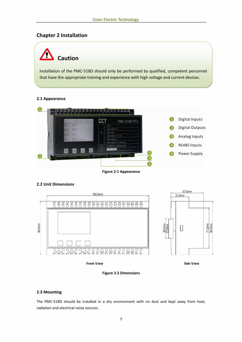
2.1 Appearance
Figure 2-1 Appearance
2.2 Unit Dimensions
Front View Side View
Figure 2-2 Dimensions
2.3 Mounting
The PMC-518D should be installed in a dry environment with no dust and kept away from heat,
radiation and electrical noise sources.
Caution
Installation of the PMC-518D should only be performed by qualified, competent personnel
that have the appropriate training and experience with high voltage and current devices.
10
Ceiec Electric Technology
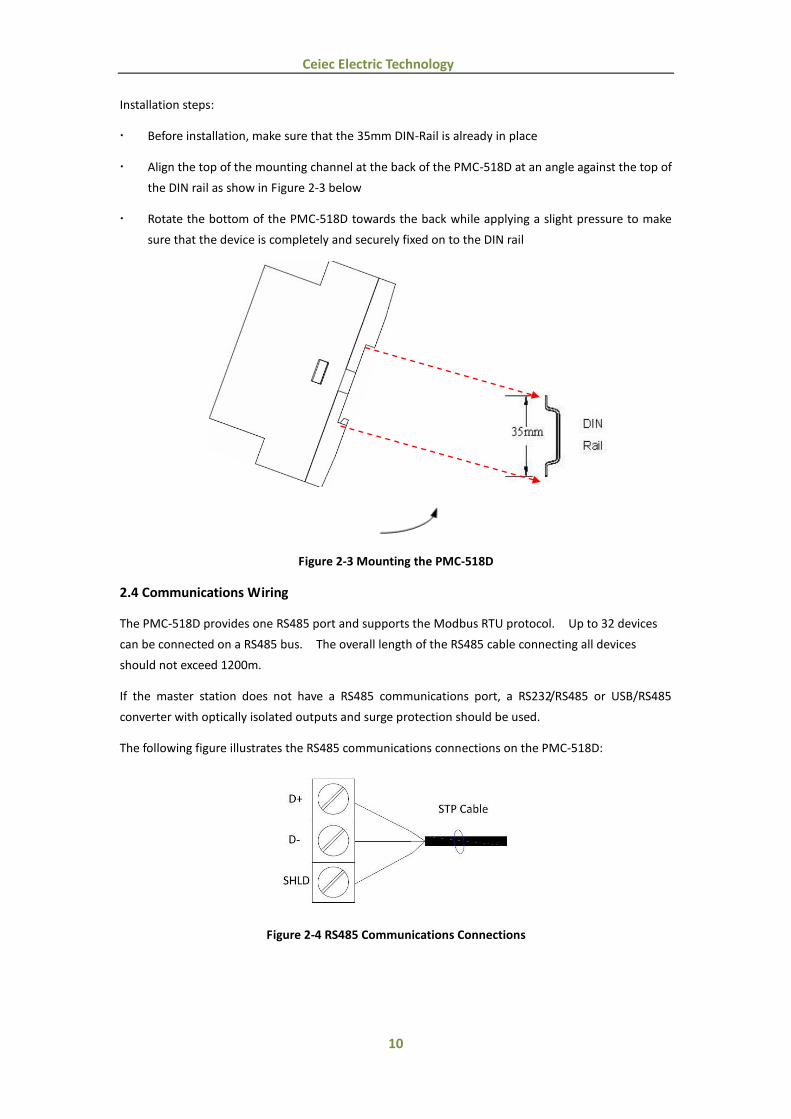
Installation steps:
Before installation, make sure that the 35mm DIN-Rail is already in place
Align the top of the mounting channel at the back of the PMC-518D at an angle against the top of
the DIN rail as show in Figure 2-3 below
Rotate the bottom of the PMC-518D towards the back while applying a slight pressure to make
sure that the device is completely and securely fixed on to the DIN rail
Figure 2-3 Mounting the PMC-518D
2.4 Communications Wiring
The PMC-518D provides one RS485 port and supports the Modbus RTU protocol. Up to 32 devices
can be connected on a RS485 bus. The overall length of the RS485 cable connecting all devices
should not exceed 1200m.
If the master station does not have a RS485 communications port, a RS232/RS485 or USB/RS485
converter with optically isolated outputs and surge protection should be used.
The following figure illustrates the RS485 communications connections on the PMC-518D:
Figure 2-4 RS485 Communications Connections

11
Ceiec Electric Technology
2.5 Digital Input Wiring
The following figure illustrates the Digital Input connections on the PMC-518D:
Figure 2-5 DI Connections
2.6 Digital Output Wiring
The following figure illustrates the Digital Output connections on the PMC-518D:
Figure 2-6 DO Connections
12
Ceiec Electric Technology
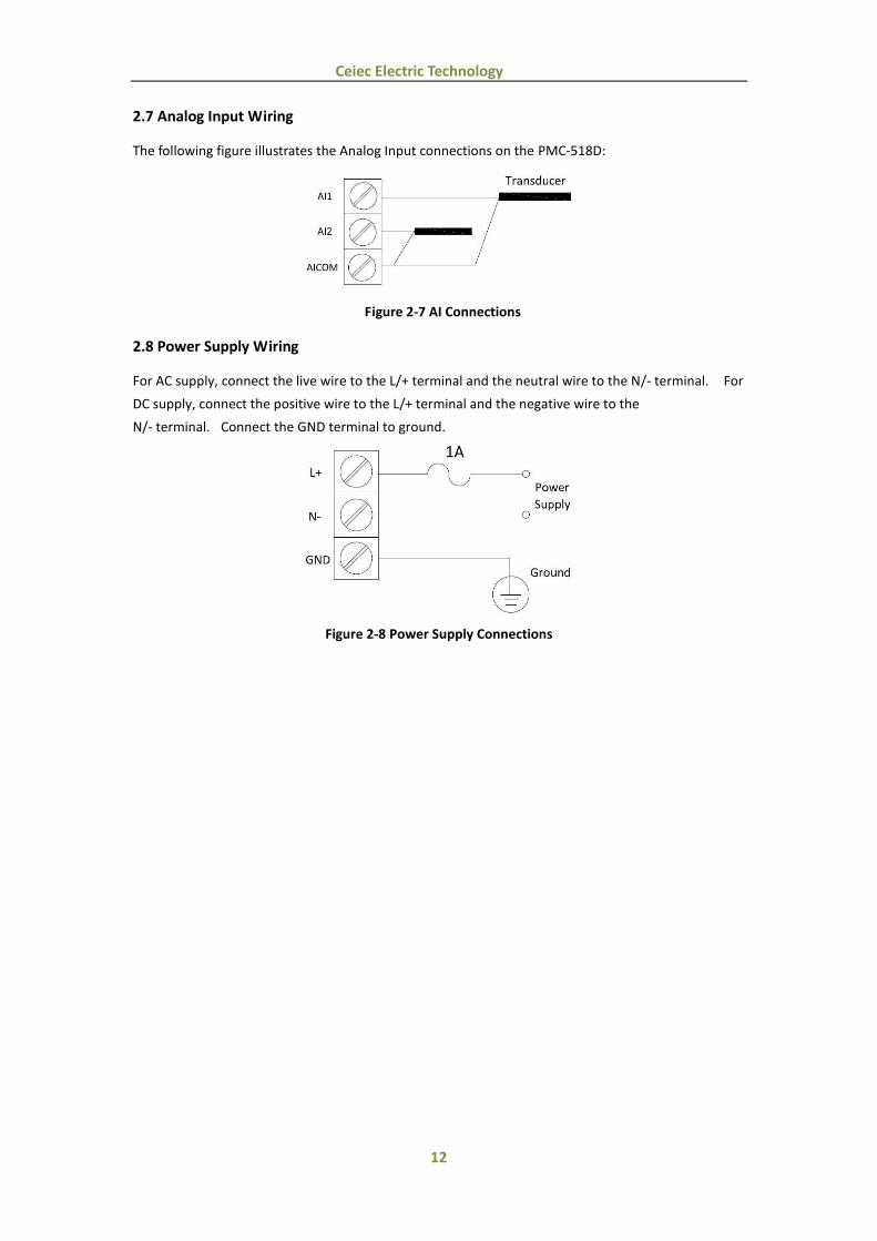
2.7 Analog Input Wiring
The following figure illustrates the Analog Input connections on the PMC-518D:
Figure 2-7 AI Connections
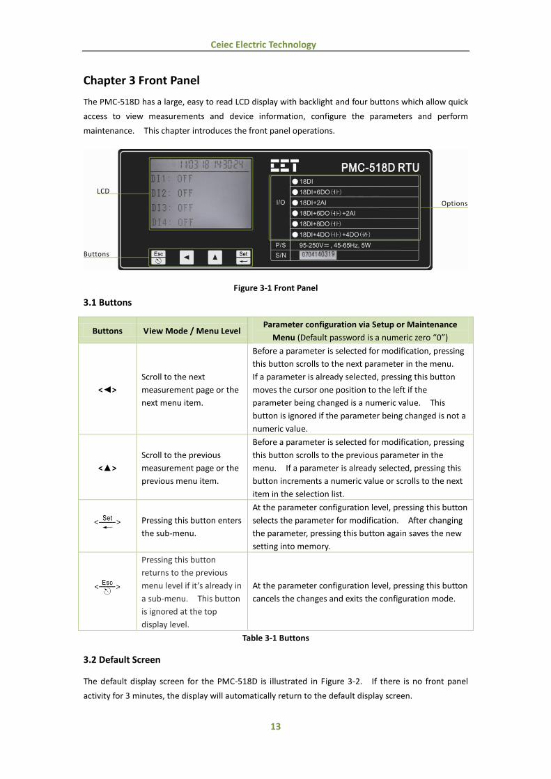
2.8 Power Supply Wiring
For AC supply, connect the live wire to the L/+ terminal and the neutral wire to the N/- terminal. For
DC supply, connect the positive wire to the L/+ terminal and the negative wire to the
N/- terminal. Connect the GND terminal to ground.
Figure 2-8 Power Supply Connections
13
Ceiec Electric Technology
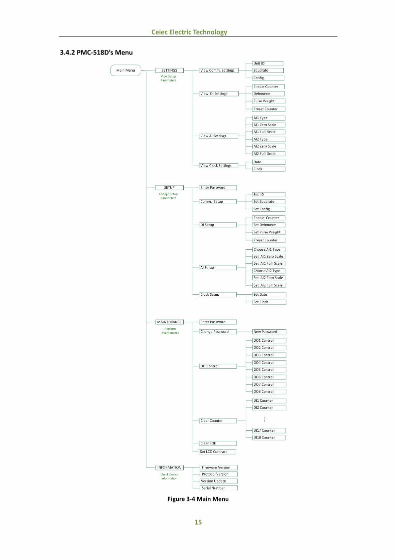
Chapter 3 Front Panel
The PMC-518D has a large, easy to read LCD display with backlight and four buttons which allow quick
access to view measurements and device information, configure the parameters and perform
maintenance. This chapter introduces the front panel operations.
Figure 3-1 Front Panel
3.1 Buttons
Buttons View Mode / Menu Level Parameter configuration via Setup or Maintenance
Menu (Default password is a numeric zero “0”)
<>
Scroll to the next
measurement page or the
next menu item.
Before a parameter is selected for modification, pressing
this button scrolls to the next parameter in the menu.
If a parameter is already selected, pressing this button
moves the cursor one position to the left if the
parameter being changed is a numeric value. This
button is ignored if the parameter being changed is not a
numeric value.
<>
Scroll to the previous
measurement page or the
previous menu item.
Before a parameter is selected for modification, pressing
this button scrolls to the previous parameter in the
menu. If a parameter is already selected, pressing this
button increments a numeric value or scrolls to the next
item in the selection list.
Pressing this button enters
the sub-menu.
At the parameter configuration level, pressing this button
selects the parameter for modification. After changing
the parameter, pressing this button again saves the new
setting into memory.
Pressing this button
returns to the previous
menu level if it’s already in
a sub-menu. This button
is ignored at the top
display level.
At the parameter configuration level, pressing this button
cancels the changes and exits the configuration mode.
Table 3-1 Buttons
3.2 Default Screen
The default display screen for the PMC-518D is illustrated in Figure 3-2. If there is no front panel
activity for 3 minutes, the display will automatically return to the default display screen.

14
Ceiec Electric Technology
Figure 3-2 PMC-518D Default Display Screen
3.3 Data Display
From the default display screen, pressing button <> views the measurements data. The following
table illustrates the data display screens for the PMC-518D.
Press Button Display Screens Parameters
<>
Display 1(default) DI1-DI4
Display 2 DI5-DI8
Display 3 DI9-DI12
Display 4 DI13-DI16
Display 5 DI17-DI18
Display 61
DO1-DO6 or DO1-DO8
Display 72
AI1-AI2
Table 3-2 PMC-518D Data Display Screens
Note:
(1) When the I/O option is 18DI or 18DI+2AI, the screens that display the DO statuses do not
appear.
(2) When the I/O option is 18DI or 18DI+6DO, the screen that displays the AI values does not
appear.
3.4 Main Menu
3.4.1 Main Screen
Pressing the <Set> button enters PMC-518D's Main Menu, which is illustrated in Figure 3-3.
Figure 3-3 PMC-518D's Main Menu
There are four options in the main menu - SETTINGS, SETUP, MAINTENANCE, and INFORMATION.
Choose SETTINGS to view the setup parameters; choose SETUP to configure the setup parameters;
choose MAINTENANCE to perform maintenance; and choose INFORMATION to view device
information.
15
Ceiec Electric Technology
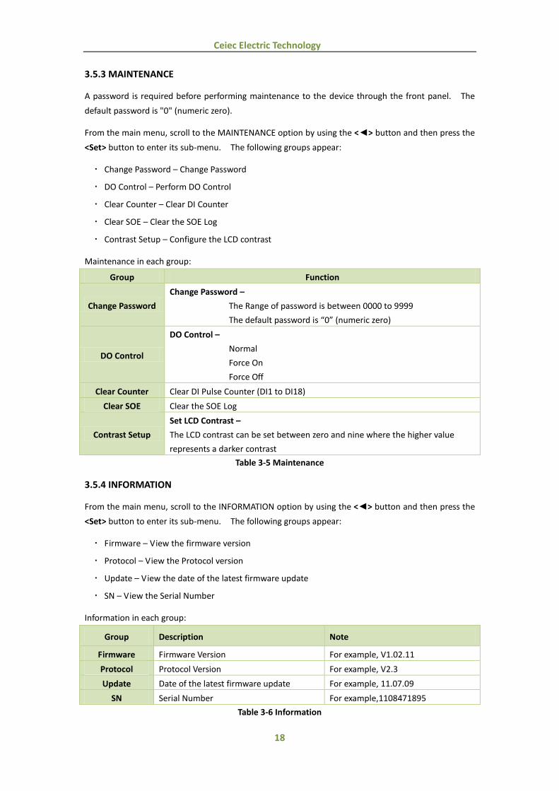
3.4.2 PMC-518D’s Menu
Figure 3-4 Main Menu

16
Ceiec Electric Technology
3.5 Using the Main Menu
There are four options in the main menu:
Figure 3-5 Main screen
SETTINGS – View setup parameters
SETUP – Configure setup parameters
MAINTENANCE – Perform maintenance
INFORMATION – View device information
This section describes front panel navigation within each option.
3.5.1 SETTINGS
From the main menu, scroll to the SETTINGS option by using the <> button and then press the
<Set> button to enter its sub-menu. The following groups appear:
Comm. Setup – View the communication setup parameters
DI Setup – View the DI setup parameters
AI Setup – View the AI setup parameters
Clock Setup – View the date and clock
Settings in each group:
Group Settings
Setup Parameters Rang/Options
Comm. Setup
Unit ID 1 to 247
Baudrate 1200/2400/4800/9600/19200bps
Configuration 8N2/8O1/8E1/8N1/8O2/8E2
DI Setup
Counter Enable E(Enable)/D(Disable)
Debounce 1 to 1000ms
Pulse Weight 0.001 to 1000.000
Counter Preset 0.000 to 999,999.999
AI Setup
AI1 Type 0-20mA/4-20mA
AI1 Zero -999,999 to 999,999
AI1 Full -999,999 to 999,999
AI2 Type 0-20mA/4-20mA
AI2 Zero -999,999 to 999,999
AI2 Full -999,999 to 999,999
Clock Setup Date 20YY/MM/DD
Clock HH:MM:SS
Table 3-3 Settings

17
Ceiec Electric Technology
3.5.2 SETUP
Setup configuration via the front panel is password protected. The user is required to enter a
password before making configuration changes to the device through the front panel. The default
password is "0" (numeric zero).
From the main menu, scroll to the SETUP option by using the <> button and then press the <Set>
button to enter its sub-menu. The following groups appear:
Comm. Setup – Configure communication setup parameters
DI Setup – Configure DI setup parameters
AI Setup – Configure AI setup parameters
Clock Setup – Configure the date and clock settings
Configuration in each group:
Group Configuration
Parameters Description Range/Options
Comm. Setup
ID Modbus Address 1 to 247
Baudrate Data rate in bits per second 1200/2400/4800/
9600/19200bps
Config. Data Format 8N2/8O1/8E1/8N1/8O2/8E2
DI Setup
Counter Enable Enable Pulse Counter E(Enable)/D(Disable)
Debounce Debounce time 1 to 1000ms
Pulse Weight Pulse Weight 0.001 to 1000.000
Counter Preset Preset Pulse Counter value 0.000 to 999,999.999
AI Setup
AI1 Type Select between 0-20mA or 4-20mA 0-20mA/4-20mA
AI1 Zero The value that corresponds to the
minimum Analog Input of 0 mA or 4 mA -999,999 to 999,999
AI1 Full The value that corresponds to the
maximum Analog Input of 20 mA -999,999 to 999,999
AI2 Type Select between 0-20mA or 4-20mA input 0-20mA/4-20mA
AI2 Zero The value that corresponds to the
minimum Analog Input of 0 mA or 4 mA -999,999 to 999,999
AI2 Full The value that corresponds to the
maximum Analog Input of 20 mA -999,999 to 999,999
Clock Setup Date Date of the device 20YY/MM/DD
Clock Clock of the device HH:MM:SS
Table 3-4 Setups
18
Ceiec Electric Technology
3.5.3 MAINTENANCE
A password is required before performing maintenance to the device through the front panel. The
default password is "0" (numeric zero).
From the main menu, scroll to the MAINTENANCE option by using the <> button and then press the
<Set> button to enter its sub-menu. The following groups appear:
Change Password – Change Password
DO Control – Perform DO Control
Clear Counter – Clear DI Counter
Clear SOE – Clear the SOE Log
Contrast Setup – Configure the LCD contrast
Maintenance in each group:
Group Function
Change Password
Change Password –
The Range of password is between 0000 to 9999
The default password is “0” (numeric zero)
DO Control
DO Control –
Normal
Force On
Force Off
Clear Counter Clear DI Pulse Counter (DI1 to DI18)
Clear SOE Clear the SOE Log
Contrast Setup
Set LCD Contrast –
The LCD contrast can be set between zero and nine where the higher value
represents a darker contrast
Table 3-5 Maintenance
3.5.4 INFORMATION
From the main menu, scroll to the INFORMATION option by using the <> button and then press the
<Set> button to enter its sub-menu. The following groups appear:
Firmware – View the firmware version
Protocol – View the Protocol version
Update – View the date of the latest firmware update
SN – View the Serial Number
Information in each group:
Group Description Note
Firmware Firmware Version For example, V1.02.11
Protocol Protocol Version For example, V2.3
Update Date of the latest firmware update For example, 11.07.09
SN Serial Number For example,1108471895
Table 3-6 Information
19
Ceiec Electric Technology
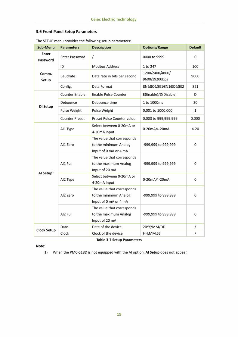
3.6 Front Panel Setup Parameters
The SETUP menu provides the following setup parameters:
Sub-Menu Parameters Description Options/Range Default
Enter
Password Enter Password / 0000 to 9999 0
Comm.
Setup
ID Modbus Address 1 to 247 100
Baudrate Data rate in bits per second 1200/2400/4800/
9600/19200bps 9600
Config. Data Format 8N2/8O1/8E1/8N1/8O2/8E2 8E1
DI Setup
Counter Enable Enable Pulse Counter E(Enable)/D(Disable) D
Debounce Debounce time 1 to 1000ms 20
Pulse Weight Pulse Weight 0.001 to 1000.000 1
Counter Preset Preset Pulse Counter value 0.000 to 999,999.999 0.000
AI Setup1
AI1 Type Select between 0-20mA or
4-20mA input 0-20mA/4-20mA 4-20
AI1 Zero
The value that corresponds
to the minimum Analog
Input of 0 mA or 4 mA
-999,999 to 999,999 0
AI1 Full
The value that corresponds
to the maximum Analog
Input of 20 mA
-999,999 to 999,999 0
AI2 Type Select between 0-20mA or
4-20mA input 0-20mA/4-20mA 0
AI2 Zero
The value that corresponds
to the minimum Analog
Input of 0 mA or 4 mA
-999,999 to 999,999 0
AI2 Full
The value that corresponds
to the maximum Analog
Input of 20 mA
-999,999 to 999,999 0
Clock Setup Date Date of the device 20YY/MM/DD /
Clock Clock of the device HH:MM:SS /
Table 3-7 Setup Parameters
Note:
1) When the PMC-518D is not equipped with the AI option, AI Setup does not appear.
20
Ceiec Electric Technology
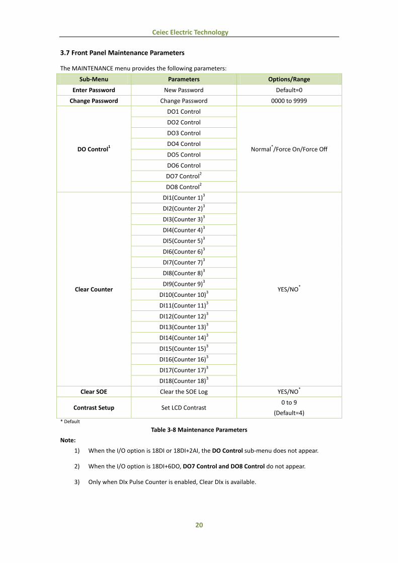
3.7 Front Panel Maintenance Parameters
The MAINTENANCE menu provides the following parameters:
Sub-Menu Parameters Options/Range
Enter Password New Password Default=0
Change Password Change Password 0000 to 9999
DO Control1
DO1 Control
Normal*/Force On/Force Off
DO2 Control
DO3 Control
DO4 Control
DO5 Control
DO6 Control
DO7 Control2
DO8 Control2
Clear Counter
DI1(Counter 1)3
YES/NO*
DI2(Counter 2)3
DI3(Counter 3)3
DI4(Counter 4)3
DI5(Counter 5)3
DI6(Counter 6)3
DI7(Counter 7)3
DI8(Counter 8)3
DI9(Counter 9)3
DI10(Counter 10)3
DI11(Counter 11)3
DI12(Counter 12)3
DI13(Counter 13)3
DI14(Counter 14)3
DI15(Counter 15)3
DI16(Counter 16)3
DI17(Counter 17)3
DI18(Counter 18)3
Clear SOE Clear the SOE Log YES/NO*
Contrast Setup Set LCD Contrast 0 to 9
(Default=4) * Default
Table 3-8 Maintenance Parameters
Note:
1) When the I/O option is 18DI or 18DI+2AI, the DO Control sub-menu does not appear.
2) When the I/O option is 18DI+6DO, DO7 Control and DO8 Control do not appear.
3) Only when DIx Pulse Counter is enabled, Clear DIx is available.
21
Ceiec Electric Technology
Chapter 4 Applications
4.1 Digital Inputs
The PMC-518D comes standard with eighteen self-excited Digital Inputs that are internally wetted at
24 VDC.
Digital Inputs are typically used for monitoring external status which can help prevent equipment
damage, improve maintenance, and track security breaches. The real-time statuses of the Digital
Inputs are available on the front panel LCD Display as well as through communications. Changes in
Digital Input status are stored as events in the SOE Log in 1 ms resolution.
Besides, Digital Inputs can also be used for pulse counting to collect WAGES (Water, Air, Gas, Electricity
and Steam) information. The WAGES information is available on the front panel LCD display as well
as through communication.
4.2 Digital Outputs
The PMC-518D comes optionally with six or eight Form A Electromechanical Digital Outputs,
which can be used for remote control applications.
4.3 Analog Input
Analog Inputs are normally used for monitoring a wide range of conditions such as flow rates, RPM,
fluid levels, oil pressures and transformer temperatures. The PMC-518D comes optionally with two
Analog Inputs which can be programmed as 0mA to 20mA or 4mA to 20mA input.
There are 3 setup parameters:
Type: Select between 0-20mA or 4-20mA input.
AI Zero: This value corresponds to the minimum Analog Input of 0 mA (for 0-20mA input) or
4 mA (for 4-20mA input) and has a range of -999,999 to +999,999.
AI Full: This value corresponds to the maximum Analog Input of 20 mA and has a range of
-999,999 to +999,999.
For example, to measure the oil temperature of a transformer, connect the outputs of the
temperature sensor to the AI terminals of the PMC-518D. The temperature sensor outputs 4mA
when the temperature is -25°C and 20mA when the temperature is 100°C . As such, the Type
parameter should be programmed as 4-20mA. The AI FULL parameter should be programmed with
the value 100, and the AI ZERO parameter should be programmed with the value -25. Therefore,
when the output of the sensor is 20mA, the reading will be 100.00°C. When the output is 4mA, the
reading will be -25.00°C. When the output is 12mA, the reading will be (100°C - (-25°C)) x
(12mA-4mA) / (20mA-4mA) + (-25°C) = 37.50°C.
4.4 SOE Log
The PMC-518D’s SOE Log can store up to 128 events such as power-on, power-off, Digital
Input/Output status changes and setup changes in its non-volatile memory. Each event record
includes the event classification, its relevant parameter values and a timestamp in 1ms resolution.
All events can be retrieved via communications for display. If there are more than 128 events, the
22
Ceiec Electric Technology
newest event will replace the oldest event on a first-in-first-out basis. The SOE Log can be reset from
the front panel or via communications.
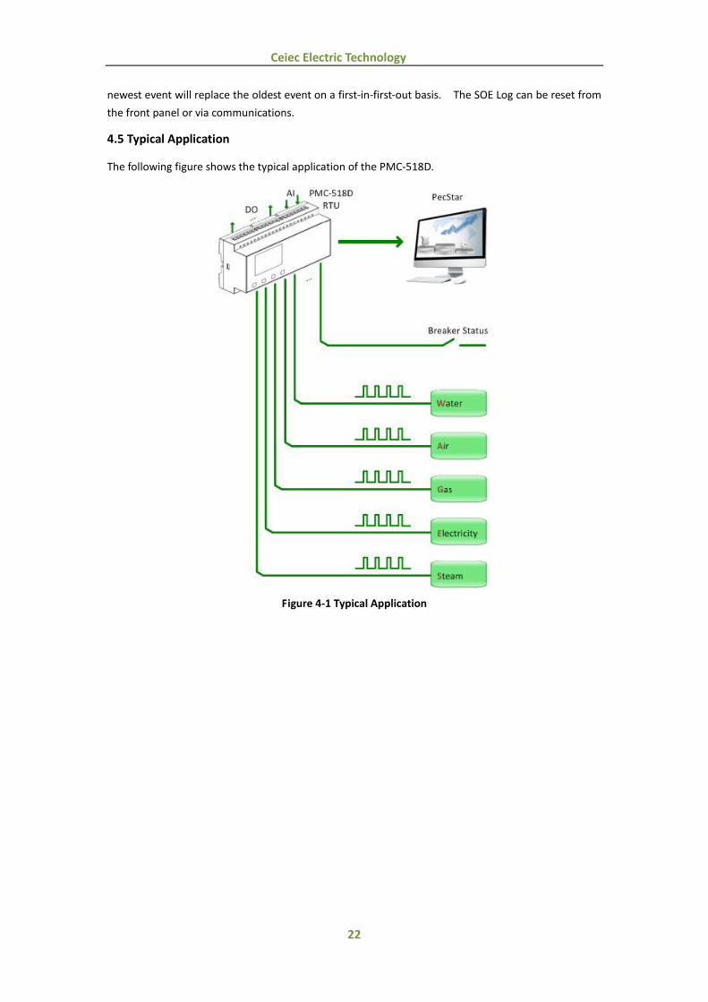
4.5 Typical Application
The following figure shows the typical application of the PMC-518D.
Figure 4-1 Typical Application
23
Ceiec Electric Technology
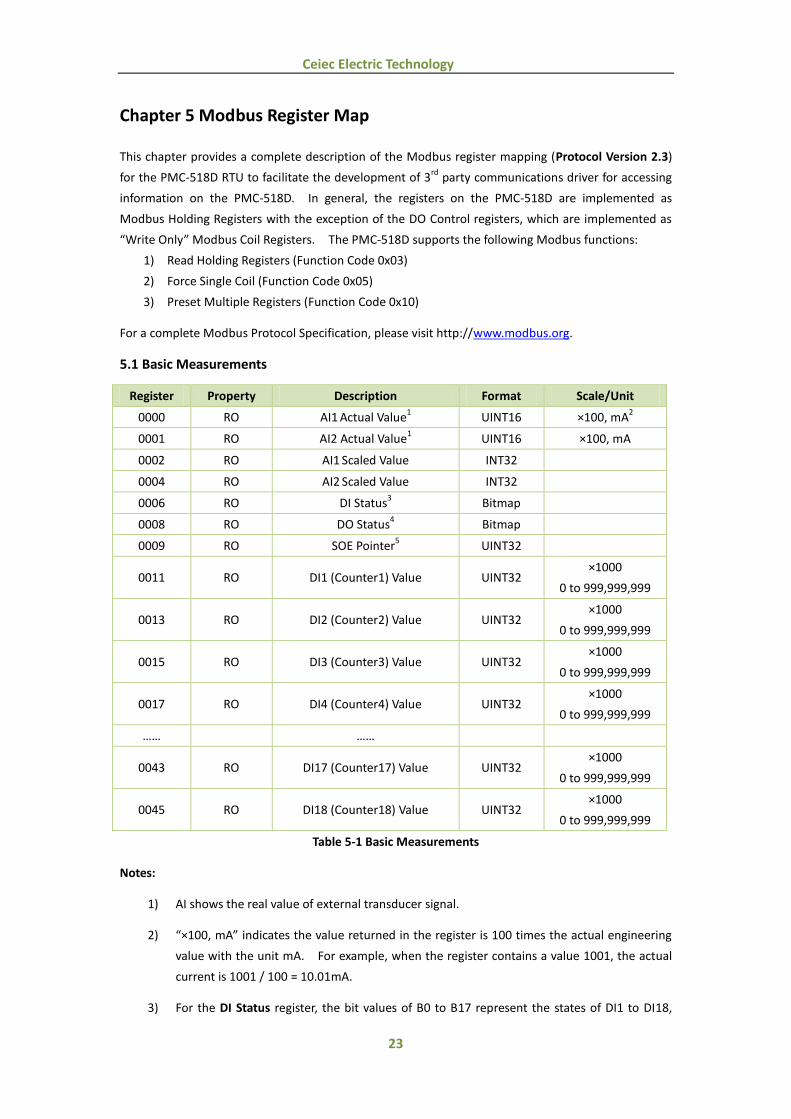
Chapter 5 Modbus Register Map
This chapter provides a complete description of the Modbus register mapping (Protocol Version 2.3)
for the PMC-518D RTU to facilitate the development of 3rd
party communications driver for accessing
information on the PMC-518D. In general, the registers on the PMC-518D are implemented as
Modbus Holding Registers with the exception of the DO Control registers, which are implemented as
“Write Only” Modbus Coil Registers. The PMC-518D supports the following Modbus functions:
1) Read Holding Registers (Function Code 0x03)
2) Force Single Coil (Function Code 0x05)
3) Preset Multiple Registers (Function Code 0x10)
For a complete Modbus Protocol Specification, please visit http://www.modbus.org.
5.1 Basic Measurements
Register Property Description Format Scale/Unit
0000 RO AI1 Actual Value
1 UINT16 ×100, mA
2
0001 RO AI2 Actual Value1 UINT16 ×100, mA
0002 RO AI1 Scaled Value INT32
0004 RO AI2 Scaled Value INT32
0006 RO DI Status3 Bitmap
0008 RO DO Status4 Bitmap
0009 RO SOE Pointer5 UINT32
0011 RO DI1 (Counter1) Value UINT32 ×1000
0 to 999,999,999
0013 RO DI2 (Counter2) Value UINT32 ×1000
0 to 999,999,999
0015 RO DI3 (Counter3) Value UINT32 ×1000
0 to 999,999,999
0017 RO DI4 (Counter4) Value UINT32 ×1000
0 to 999,999,999
…… ……
0043 RO DI17 (Counter17) Value UINT32 ×1000
0 to 999,999,999
0045 RO DI18 (Counter18) Value UINT32 ×1000
0 to 999,999,999
Table 5-1 Basic Measurements
Notes:
1) AI shows the real value of external transducer signal.
2) “×100, mA” indicates the value returned in the register is 100 times the actual engineering
value with the unit mA. For example, when the register contains a value 1001, the actual
current is 1001 / 100 = 10.01mA.
3) For the DI Status register, the bit values of B0 to B17 represent the states of DI1 to DI18,

24
Ceiec Electric Technology
respectively, with “1” meaning active (closed) and “0” meaning inactive (open).
4) For the DO Status register, the bit values of B0 to B7 represent the states of DO1 to DO8,
respectively, with “1” meaning active (Operated) and “0” meaning inactive (Released).
5) The range of the SOE Pointer is between 0 and 0xFFFFFFFF. The SOE Pointer is
incremented by one for every event generated and will roll over to 0 if its current value is
0xFFFFFFFF. Since the SOE Pointer is a 32-bit value and the SOE Log capacity is relatively
small with only 128 events in the PMC-518D, an assumption has been made that the SOE
pointer will never roll over. If a Clear SOE is performed from the front panel or via
communications, the SOE Pointer will be reset to zero and then immediately incremented
by one with a new ”Clear SOE via Front Panel” or “Clear SOE via Communications” event.
Therefore, any 3rd
party software should assume that a Clear SOE action has been
performed if it sees the SOE Pointer rolling over to one or to a value that is smaller than its
own pointer. In this case, the new SOE Pointer also indicates the number of events in the
SOE Log if it is less than 128. Otherwise, there will always be 128 events in the SOE Log.
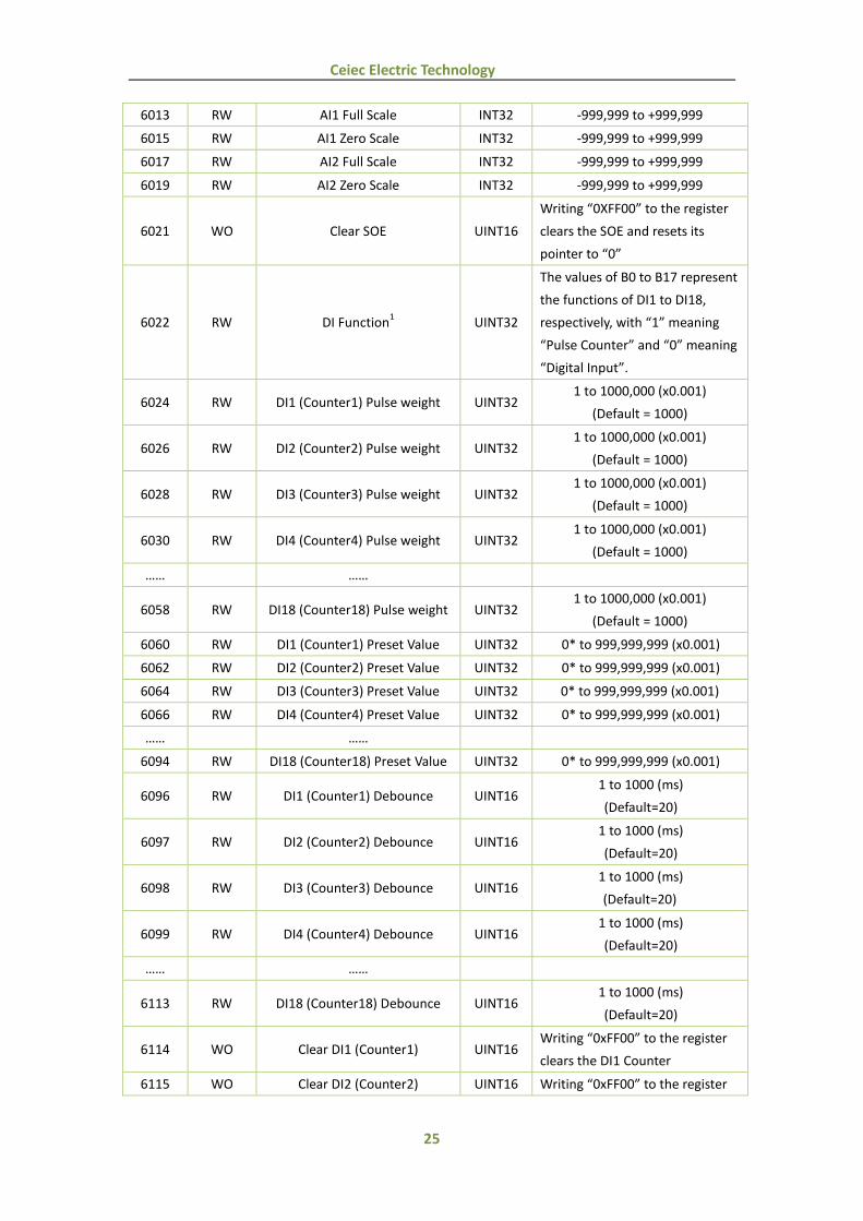
5.2 Setup Parameters
Register Property Description Format Range/Options
6000 RW Unit ID UINT16 1 to 247
(Default = 100)
6001 RW Baud rate UINT16
0=1200
1=2400
2=4800
3=9600*
4=19200
6002 RW Configuration UINT16
0=8N2
1=8O1
2=8E1*
3=8N1
4=8O2
5=8E2
6003 RW DO1 Pulse Width UINT16
0* to 600 (x0.1s)
0 = Latch Mode
6004 RW DO2 Pulse Width UINT16
6005 RW DO3 Pulse Width UINT16
6006 RW DO4 Pulse Width UINT16
6007 RW DO5 Pulse Width UINT16
6008 RW DO6 Pulse Width UINT16
6009 RW DO7 Pulse Width UINT16
6010 RW DO8 Pulse Width UINT16
6011 RW AI1 Type UINT16 0= 4-20mA*
1= 0-20mA
6012 RW AI2 Type UINT16 0= 4-20mA*
1= 0-20mA
25
Ceiec Electric Technology
6013 RW AI1 Full Scale INT32 -999,999 to +999,999
6015 RW AI1 Zero Scale INT32 -999,999 to +999,999
6017 RW AI2 Full Scale INT32 -999,999 to +999,999
6019 RW AI2 Zero Scale INT32 -999,999 to +999,999
6021 WO Clear SOE UINT16
Writing “0XFF00” to the register
clears the SOE and resets its
pointer to “0”
6022 RW DI Function1 UINT32
The values of B0 to B17 represent
the functions of DI1 to DI18,
respectively, with “1” meaning
“Pulse Counter” and “0” meaning
“Digital Input”.
6024 RW DI1 (Counter1) Pulse weight UINT32 1 to 1000,000 (x0.001)
(Default = 1000)
6026 RW DI2 (Counter2) Pulse weight UINT32 1 to 1000,000 (x0.001)
(Default = 1000)
6028 RW DI3 (Counter3) Pulse weight UINT32 1 to 1000,000 (x0.001)
(Default = 1000)
6030 RW DI4 (Counter4) Pulse weight UINT32 1 to 1000,000 (x0.001)
(Default = 1000)
…… ……
6058 RW DI18 (Counter18) Pulse weight UINT32 1 to 1000,000 (x0.001)
(Default = 1000)
6060 RW DI1 (Counter1) Preset Value UINT32 0* to 999,999,999 (x0.001)
6062 RW DI2 (Counter2) Preset Value UINT32 0* to 999,999,999 (x0.001)
6064 RW DI3 (Counter3) Preset Value UINT32 0* to 999,999,999 (x0.001)
6066 RW DI4 (Counter4) Preset Value UINT32 0* to 999,999,999 (x0.001)
…… ……
6094 RW DI18 (Counter18) Preset Value UINT32 0* to 999,999,999 (x0.001)
6096 RW DI1 (Counter1) Debounce UINT16 1 to 1000 (ms)
(Default=20)
6097 RW DI2 (Counter2) Debounce UINT16 1 to 1000 (ms)
(Default=20)
6098 RW DI3 (Counter3) Debounce UINT16 1 to 1000 (ms)
(Default=20)
6099 RW DI4 (Counter4) Debounce UINT16 1 to 1000 (ms)
(Default=20)
…… ……
6113 RW DI18 (Counter18) Debounce UINT16 1 to 1000 (ms)
(Default=20)
6114 WO Clear DI1 (Counter1) UINT16 Writing “0xFF00” to the register
clears the DI1 Counter
6115 WO Clear DI2 (Counter2) UINT16 Writing “0xFF00” to the register
26
Ceiec Electric Technology
clears the DI2 Counter
6116 WO Clear DI3 (Counter3) UINT16 Writing “0xFF00” to the register
clears the DI3 Counter
6117 WO Clear DI4 (Counter4) UINT16 Writing “0xFF00” to the register
clears the DI4 Counter
…… ……
6131 WO Clear DI18 (Counter18) UINT16 Writing “0xFF00” to the register
clears the DI18 Counter * Default
Table 5-2 Setup Parameters
Notes:
1) The range of register 6022 is 0 to 0x3FFFF. If the value written in register 6022 exceeds
this range, the PMC-518D ignores the “Write” command and returns the 0x03 exception
code.
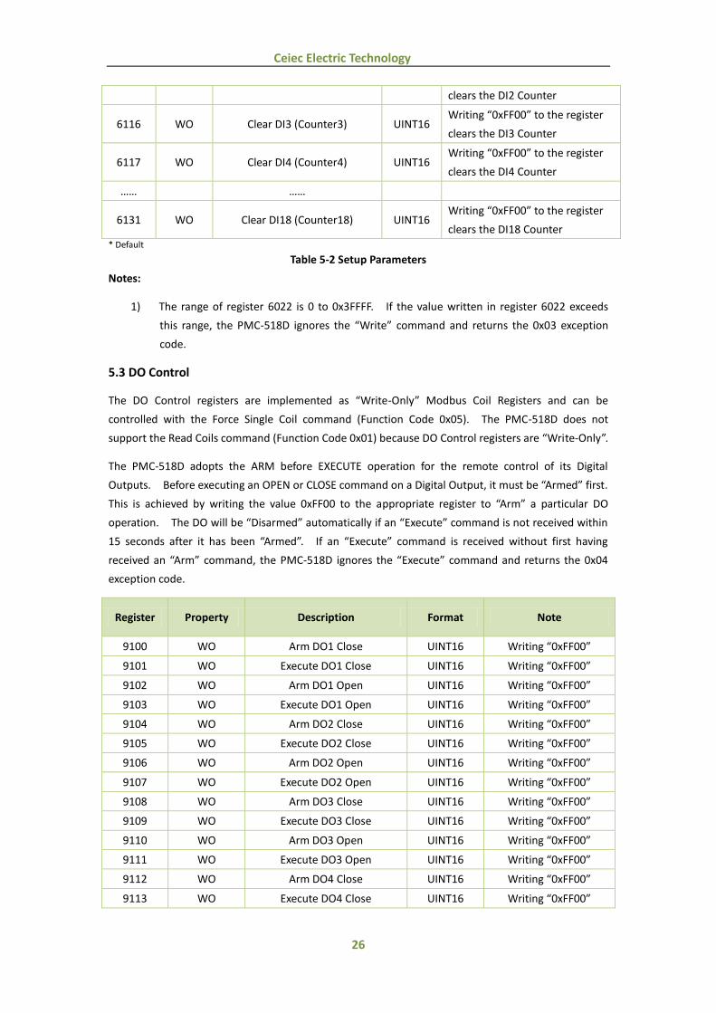
5.3 DO Control
The DO Control registers are implemented as “Write-Only” Modbus Coil Registers and can be
controlled with the Force Single Coil command (Function Code 0x05). The PMC-518D does not
support the Read Coils command (Function Code 0x01) because DO Control registers are “Write-Only”.
The PMC-518D adopts the ARM before EXECUTE operation for the remote control of its Digital
Outputs. Before executing an OPEN or CLOSE command on a Digital Output, it must be “Armed” first.
This is achieved by writing the value 0xFF00 to the appropriate register to “Arm” a particular DO
operation. The DO will be “Disarmed” automatically if an “Execute” command is not received within
15 seconds after it has been “Armed”. If an “Execute” command is received without first having
received an “Arm” command, the PMC-518D ignores the “Execute” command and returns the 0x04
exception code.
Register Property Description Format Note
9100 WO Arm DO1 Close UINT16 Writing “0xFF00”
9101 WO Execute DO1 Close UINT16 Writing “0xFF00”
9102 WO Arm DO1 Open UINT16 Writing “0xFF00”
9103 WO Execute DO1 Open UINT16 Writing “0xFF00”
9104 WO Arm DO2 Close UINT16 Writing “0xFF00”
9105 WO Execute DO2 Close UINT16 Writing “0xFF00”
9106 WO Arm DO2 Open UINT16 Writing “0xFF00”
9107 WO Execute DO2 Open UINT16 Writing “0xFF00”
9108 WO Arm DO3 Close UINT16 Writing “0xFF00”
9109 WO Execute DO3 Close UINT16 Writing “0xFF00”
9110 WO Arm DO3 Open UINT16 Writing “0xFF00”
9111 WO Execute DO3 Open UINT16 Writing “0xFF00”
9112 WO Arm DO4 Close UINT16 Writing “0xFF00”
9113 WO Execute DO4 Close UINT16 Writing “0xFF00”
27
Ceiec Electric Technology
9114 WO Arm DO4 Open UINT16 Writing “0xFF00”
9115 WO Execute DO4 Open UINT16 Writing “0xFF00”
9116 WO Arm DO5 Close UINT16 Writing “0xFF00”
9117 WO Execute DO5 Close UINT16 Writing “0xFF00”
9118 WO Arm DO5 Open UINT16 Writing “0xFF00”
9119 WO Execute DO5 Open UINT16 Writing “0xFF00”
9120 WO Arm DO6 Close UINT16 Writing “0xFF00”
9121 WO Execute DO6 Close UINT16 Writing “0xFF00”
9122 WO Arm DO6 Open UINT16 Writing “0xFF00”
9123 WO Execute DO6 Open UINT16 Writing “0xFF00”
9124 WO Arm DO7 Close UINT16 Writing “0xFF00”
9125 WO Execute DO7 Close UINT16 Writing “0xFF00”
9126 WO Arm DO7 Open UINT16 Writing “0xFF00”
9127 WO Execute DO7 Open UINT16 Writing “0xFF00”
9128 WO Arm DO8 Close UINT16 Writing “0xFF00”
9129 WO Execute DO8 Close UINT16 Writing “0xFF00”
9130 WO Arm DO8 Open UINT16 Writing “0xFF00”
9131 WO Execute DO8 Open UINT16 Writing “0xFF00”
Table 5-3 DO Control
5.4 SOE Log
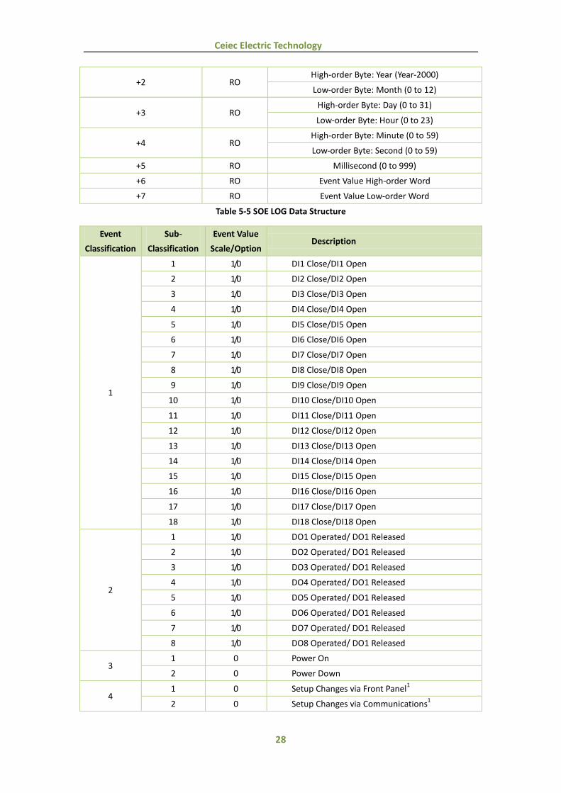
Each event occupies 8 registers as shown in the following table.
Register Property Description Format
10000-10007 RO Event 1 SOE LOG (Table 5-5)
10008-10015 RO Event 2 SOE LOG
10016-10023 RO Event 3 SOE LOG
10024-10031 RO Event 4 SOE LOG
10032-10039 RO Event 5 SOE LOG
10040-10047 RO Event 6 SOE LOG
10048-10055 RO Event 7 SOE LOG
10056-10063 RO Event 8 SOE LOG
10064-10071 RO Event 9 SOE LOG
10072-10079 RO Event 10 SOE LOG
10080-10087 RO Event 11 SOE LOG
10088-10095 RO Event 12 SOE LOG
…… SOE LOG
11016-11023 RO Event 128 SOE LOG
Table 5-4 SOE Log
Offset Properties Description
+0 RO Reserved
+1 RO High-order Byte: Event Classification (Table 5-6)
Low-order Byte: Sub-Classification (Table 5-6)
28
Ceiec Electric Technology
+2 RO High-order Byte: Year (Year-2000)
Low-order Byte: Month (0 to 12)
+3 RO High-order Byte: Day (0 to 31)
Low-order Byte: Hour (0 to 23)
+4 RO High-order Byte: Minute (0 to 59)
Low-order Byte: Second (0 to 59)
+5 RO Millisecond (0 to 999)
+6 RO Event Value High-order Word
+7 RO Event Value Low-order Word
Table 5-5 SOE LOG Data Structure
Event
Classification
Sub-
Classification
Event Value
Scale/Option Description
1
1 1/0 DI1 Close/DI1 Open
2 1/0 DI2 Close/DI2 Open
3 1/0 DI3 Close/DI3 Open
4 1/0 DI4 Close/DI4 Open
5 1/0 DI5 Close/DI5 Open
6 1/0 DI6 Close/DI6 Open
7 1/0 DI7 Close/DI7 Open
8 1/0 DI8 Close/DI8 Open
9 1/0 DI9 Close/DI9 Open
10 1/0 DI10 Close/DI10 Open
11 1/0 DI11 Close/DI11 Open
12 1/0 DI12 Close/DI12 Open
13 1/0 DI13 Close/DI13 Open
14 1/0 DI14 Close/DI14 Open
15 1/0 DI15 Close/DI15 Open
16 1/0 DI16 Close/DI16 Open
17 1/0 DI17 Close/DI17 Open
18 1/0 DI18 Close/DI18 Open
2
1 1/0 DO1 Operated/ DO1 Released
2 1/0 DO2 Operated/ DO1 Released
3 1/0 DO3 Operated/ DO1 Released
4 1/0 DO4 Operated/ DO1 Released
5 1/0 DO5 Operated/ DO1 Released
6 1/0 DO6 Operated/ DO1 Released
7 1/0 DO7 Operated/ DO1 Released
8 1/0 DO8 Operated/ DO1 Released
3 1 0 Power On
2 0 Power Down
4 1 0 Setup Changes via Front Panel
1
2 0 Setup Changes via Communications1

29
Ceiec Electric Technology
5 1 1-18 Clear DI Counter (1-18) via Front Panel
2 1-18 Clear DI Counter (1-18) via Communications
6 1 1 Clear SOE via Front Panel
2 1 Clear SOE via Communications
Table 5-6 Event Classification
Notes:
1) "Setup Changes" events include the configuration changes of DI parameters, DO parameters,
AI parameters and communication parameters.
5.5 Time
There are two sets of Time registers supported by the PMC-518D -
Year/Month/Day/Hour/Minute/Second (Register # 9000 to 9002) and UNIX Time (Register # 9004).
When sending time to the PMC-518D over Modbus communications, care should be taken to only
write one of the two Time register sets. All registers within a Time register set must be written in a
single transaction. If registers 9000 to 9004 are being written to at the same time, both Time
register sets will be updated to reflect the new time specified in the UNIX Time register set (9004) and
the time specified in registers 9000-9002 will be ignored. Writing to the Millisecond register (9003)
is optional during a Time Set operation. When broadcasting time, the function code must be set to
0x10 (Pre-set Multiple Registers). Incorrect date or time values will be rejected by the PMC-518D.
Register Property Description Format Note
9000 RW High-order Byte: Year
UINT16 0 to 99 (Year-2000)
Low-order Byte: Month 1 to 12
9001 RW High-order Byte: Day
UINT16 1 to 31
Low-order Byte: Hour 0 to 23
9002 RW High-order Byte: Minute
UINT16 0 to 59
Low-order Byte: Second 0 to 59
9003 RW Millisecond UINT16 0 to 999
9004 RW UINX Time in Second UINT32
(0 to 3155759999)
This time shows the number of
seconds that have elapsed since
January 1, 1970, at 00:00:00
Table 5-7 Time Registers
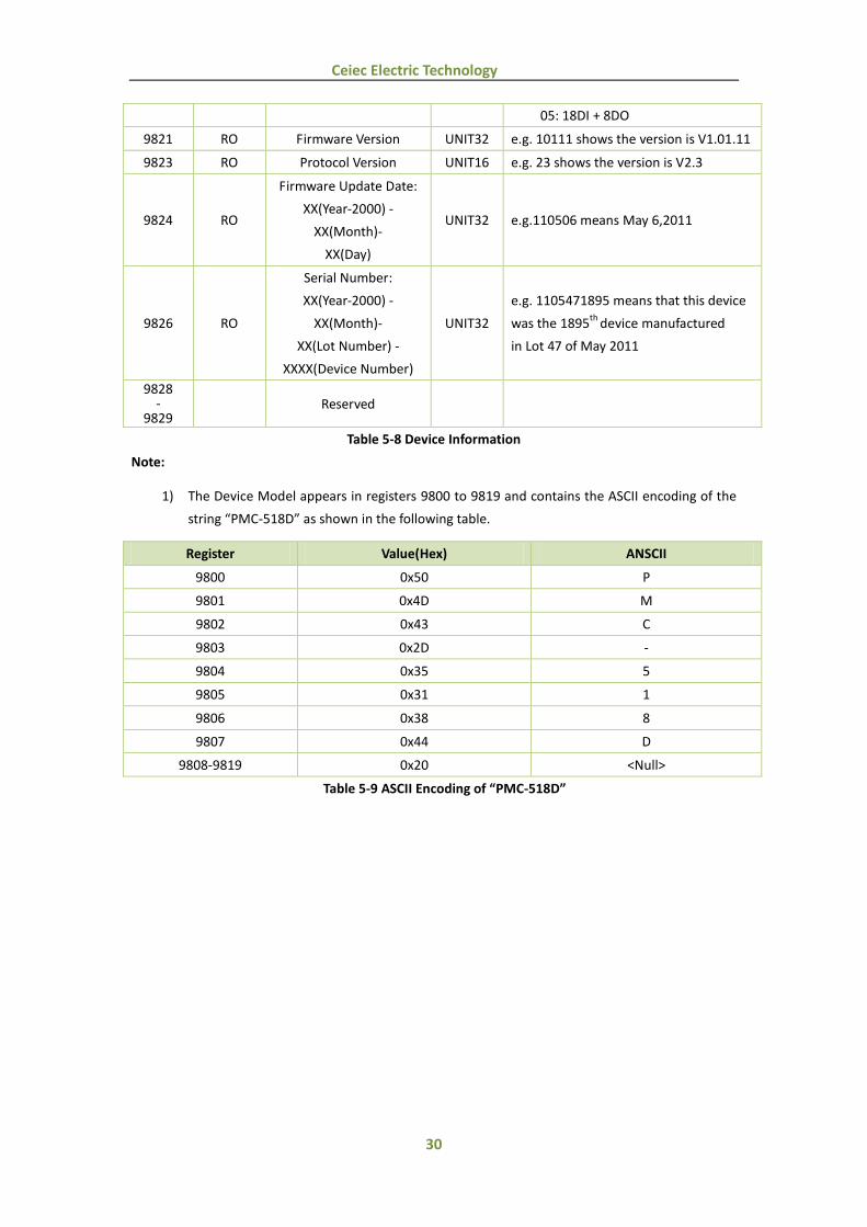
5.6 Device Information
Register Property Description Format Note
9800 -
9819 RO Device Model
1 UNIT16 PMC-518D
9820 RO Feature Code UNIT16
00: 18DI
01: 18DI + 6DO
02: 18DI + 2AI
03: 18DI + 6DO + 2AI
04: 18DI + 4DO + 4DO (NC)
30
Ceiec Electric Technology
05: 18DI + 8DO
9821 RO Firmware Version UNIT32 e.g. 10111 shows the version is V1.01.11
9823 RO Protocol Version UNIT16 e.g. 23 shows the version is V2.3
9824 RO
Firmware Update Date:
XX(Year-2000) -
XX(Month)-
XX(Day)
UNIT32 e.g.110506 means May 6,2011
9826 RO
Serial Number:
XX(Year-2000) -
XX(Month)-
XX(Lot Number) -
XXXX(Device Number)
UNIT32
e.g. 1105471895 means that this device
was the 1895th
device manufactured
in Lot 47 of May 2011
9828 -
9829 Reserved
Table 5-8 Device Information
Note:
1) The Device Model appears in registers 9800 to 9819 and contains the ASCII encoding of the
string “PMC-518D” as shown in the following table.
Register Value(Hex) ANSCII
9800 0x50 P
9801 0x4D M
9802 0x43 C
9803 0x2D -
9804 0x35 5
9805 0x31 1
9806 0x38 8
9807 0x44 D
9808-9819 0x20 <Null>
Table 5-9 ASCII Encoding of “PMC-518D”
31
Ceiec Electric Technology
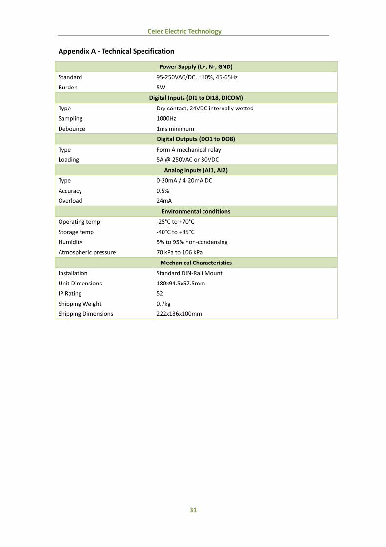
Appendix A - Technical Specification
Power Supply (L+, N-, GND)
Standard
Burden
95-250VAC/DC, ±10%, 45-65Hz
5W
Digital Inputs (DI1 to DI18, DICOM)
Type
Sampling
Debounce
Dry contact, 24VDC internally wetted
1000Hz
1ms minimum
Digital Outputs (DO1 to DO8)
Type
Loading
Form A mechanical relay
5A @ 250VAC or 30VDC
Analog Inputs (AI1, AI2)
Type
Accuracy
Overload
0-20mA / 4-20mA DC
0.5%
24mA
Environmental conditions
Operating temp
Storage temp
Humidity
Atmospheric pressure
-25°C to +70°C
-40°C to +85°C
5% to 95% non-condensing
70 kPa to 106 kPa
Mechanical Characteristics
Installation
Unit Dimensions
IP Rating
Shipping Weight
Shipping Dimensions
Standard DIN-Rail Mount
180x94.5x57.5mm
52
0.7kg
222x136x100mm

32
Ceiec Electric Technology
Appendix B - Standards Compliance
Safety Requirements
CE LVD 2006/95/EC EN61010-1-1-2001
Insulation
Dielectric test: 2kV @ 1 minute
Insulation resistance: >100MΩ
Impulse voltage: 5kV, 1.2/50µs
IEC 60255-5-2000
Electromagnetic Compatibility
CE EMC Directive 2004/108/EC (EN 61326: 2006)
Immunity Tests
Electrostatic discharge IEC 61000-4-2:2001 Level III
Radiated fields IEC 61000-4-3:2008 (10 V/m)
Fast transients IEC 61000-4-4:2004 Level III
Surges IEC 61000-4-5:2005 Level III
Conducted disturbances IEC 61000-4-6:2006 Level III
Magnetic Fields IEC 61000-4-8:2009 Level IV
Oscillatory waves IEC 61000-4-12:1995 Level III
Radio Disturbances CISPR 22:2006, Level B
Emission Tests
Limits and methods of measurement of
electromagnetic disturbance characteristics of
industrial, scientific and medical (ISM)
radio-frequency equipment
EN 55011: 2009 (CISPR 11)
Limits and methods of measurement of radio
disturbance characteristics of information
technology equipment
EN 55022: 2006+A1: 2007
(CISPR 22)
Limits for harmonic current emissions for
equipment with rated current ≤16 A EN 61000-3-2: 2006+A1: 2009
Limitation of voltage fluctuations and flicker in
low-voltage supply systems for equipment with
rated current ≤16 A
EN 61000-3-3: 2006
Emission standard for residential, commercial
and light-industrial environments EN 61000-6-3: 2007
Electromagnetic Emission Tests for Measuring
Relays and Protection Equipment IEC 60255-25: 2000
Mechanical Tests
Vibration Test Response IEC 60255-21-1 Level I
Endurance IEC 60255-21-1 Level I
Shock Test Response IEC 60255-21-2 Level I
Endurance IEC 60255-21-2 Level I
Bump Test IEC 60255-21-2 Level I

33
Ceiec Electric Technology
Appendix C - Ordering Guide
Contact us
Ceiec Electric Technology Headquarters
8/F, Westside, Building 201, Terra Industrial & Tradepark, Che Gong Miao, Shenzhen, Guangdong,
P.R.China 518040
Tel: +86.755.8341.5187
Fax: +86.755.8341.0291
Email: [email protected]
Web: www.ceiec-electric.com