
KİLİTTAŞI Mühendislik YOOIL ENGINEERING, S.
51
KİLİTTAŞI Mühendislik YOOIL ENGINEERING S Korea YOOIL ENGINEERING, S. Korea
Transcript of KİLİTTAŞI Mühendislik YOOIL ENGINEERING, S.

KİLİTTAŞI MühendislikYOOIL ENGINEERING S KoreaYOOIL ENGINEERING, S. Korea

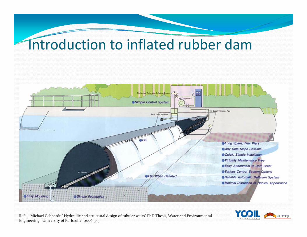
Introduction to inflated rubber damRubber dams are cylindrical rubber fabrics placed across channels, streams and weir, or dam crests to raise the upstream water level when
Introduction to inflated rubber dam
pinflated.Mainly consists of four parts:
Rubber dam bodyyConcrete foundationControl room housing mechanical and electrical equipment (air blower/water pump, inflation/deflation mechanism)
Inlet and outlet piping system
Introduction to inflated rubber damIntroduction to inflated rubber dam
Ref: Michael Gebhardt,” Hydraulic and structural design of tubular weirs” PhD Thesis, Water and Environmental Engineering– University of Karlsruhe, 2006, p.5.

Rubber dam heightAir filled rubber dams can be up to 6 m height
Rubber dam height
be up to 6 m height.
The side picture shows 5‐ h i ht bb dm height rubber dam
project located in Japan.
Yooil Engineering has the capability to manufacture and install rubber dam up t h i htto 5‐m height.
Courtesy of Electric Power Development Co., Ltd.(EPDC), Japan

HistoryHistoryThe first concept of rubber dam was developed in the 1950's by N.M. Imbertson of the Los Angeles Department of Water and Power,g p ,And manufactured as Fabridams by the Firestone Tire and Rubber Co.The first Fabridamwas installed on the Los Angeles River, California, for groundwater recharge and flood mitigation as water filled system.E l bb d t fill d t Early rubber dams were water filled systems.
A conceptual design of early rubber dams, 1961.

HistoryHistoryIn 1978, Bridgestone Corporation introduced an air‐inflated rubber damdam.By 2002, there were more than 2500 rubber dams all around the world.
Majority of them were located in Asia.

HistoryHistoryOf this 2500 rubber dam projects,
% 89.4 : air filled% 10.4 : water filled% i fill d% 0.2 : air‐water filled
The rubber dam has experienced continuous improvements and innovations since thenimprovements and innovations since then.In Turkey, it has just began to be known. Thanks to the hydroelectric power plant projects developed by y p p p j p yprivate investors.
*Ref: “Flexible structures,” International Water Power and Dam Construction, 3 Jan 2007.

Types of rubber damTypes of rubber damThere are three types of rubber dam system:
Air filled ruber damWater filled rubber damH b id bb d (fill d i h b h i d )Hybrid rubber dam (filled with both air and water)

Types of rubber damTypes of rubber damA schematic picture of hybrid rubber dam
Courtesy of Delft Hydraulics, www.widelft.nl

Comparison of air vs. water filled rubber dam systemsrubber dam systems
Air is used more often than water as the filling medium for the following reasons*:following reasons :
Water and water‐borne debris can corrode and clog pipesThe design and construction of air‐filled dams are simpler.Water‐filled dams require a more complex piping system and often q p p p g yneed a pond to store water for filling the dams when river water levels are low.The inflation and deflation time of an air‐filled dam is much shorter than that of a water‐filled dam of the same size.shorter than that of a water filled dam of the same size.Due to the weight of water, the water‐filled dam has a squat shape, requiring more rubber material than an air‐filled dam of the same height.Th i f f t fill d d i b t 8 ti it The circumference of a water‐filled dam is about 4.8 times its height, compared to 3.5 times for an air‐filled dam. To accommodate the dam body, the foundation of a water‐filled dam must be wider than that of an air‐filled dam of the same height.
*Ref: “Flexible structures,” International Water Power and Dam Construction, 3 Jan 2007.

Comparison of air vs. water filled rubber dam systemsrubber dam systems
However, air‐filled dams are less stable and suffer more from vibration than the water filled ones which are more preferable when hydraulic than the water‐filled ones, which are more preferable when hydraulic conditions are more demanding
*Ref: “Flexible structures,” International Water Power and Dam Construction, 3 Jan 2007.

Applications of rubber damsApplications of rubber damsRubber dams can be used as a weir body, and A good alternative for radial gates
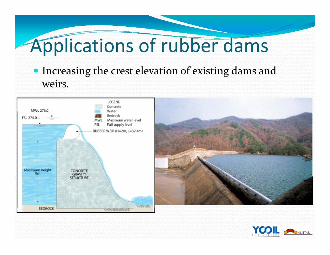
Applications of rubber damsApplications of rubber damsIncreasing the crest elevation of existing dams and weirs.

Applications of rubber damsApplications of rubber damsDebris, garbage and other wastes behind the dam can be fl h d d il i h bb d h i i flushed downstream easily with rubber dam when it is deflated,On river and ponds, it can be used for recreation purposes On river and ponds, it can be used for recreation purposes (as seen in picture given below).
Courtesy of YOOIL Engineering

Applications of rubber damsApplications of rubber damsRubber dams are widely used in hydro electric power plant
j f h f ll i projects for the following purposes:Increasing the energy production capacity by increasing the gross head (through increasing the crest elevation of the g ( g gweir)Used as weir bodyUsed instead of radial gatesUsed instead of radial gatesIncreasing the weir body heightIncreasing the crest elevation of existing weirs and dams.g gCan be used on spillways so that increase the reservoir/pond elevation (e.g. settling basin and head pond side spillway).

Rubber body materialRubber body materialRubber body material
Courtesy of YOOIL Engineering

InstallationInstallationThe rubber dam body is fixed onto a concrete foundationD di bb h i ht it i fi d b i l d bl h li Depending on rubber height, it is fixed by single or double anchor line.
Courtesy of YOOIL Engineering
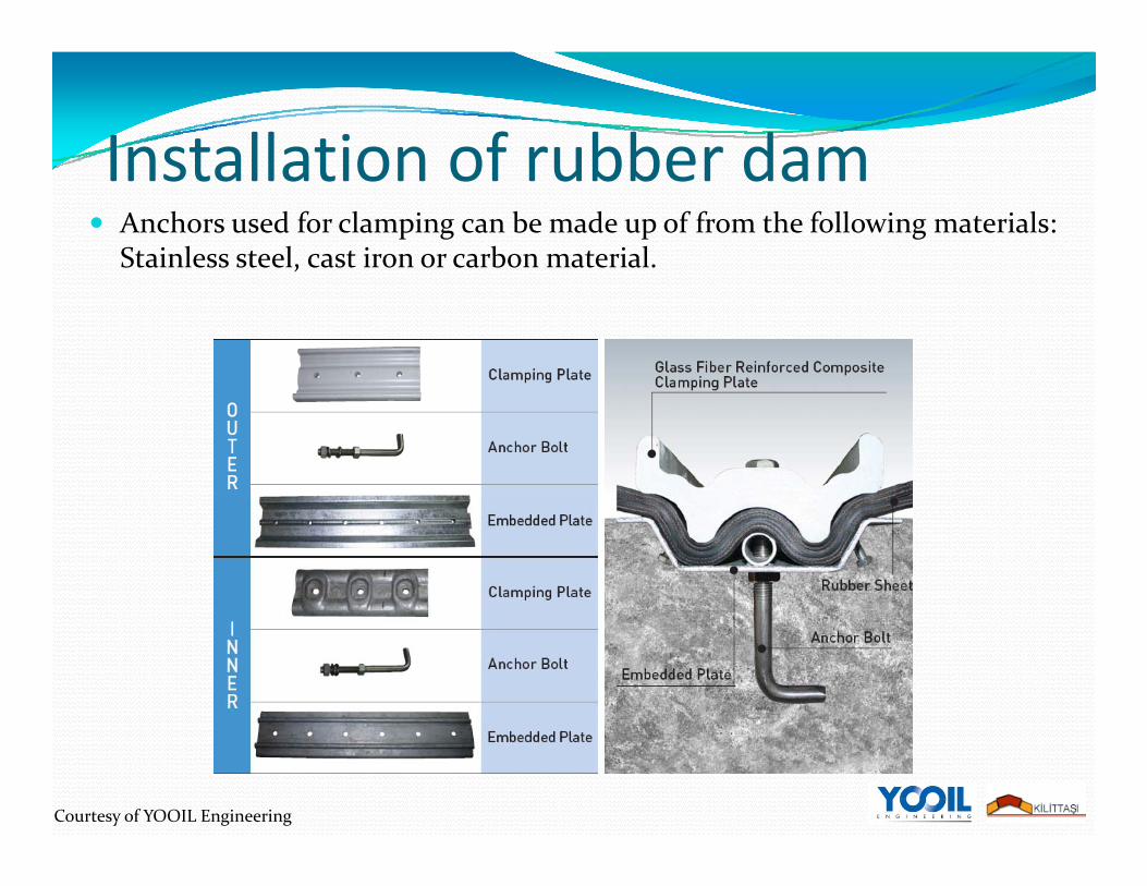
Installation of rubber damInstallation of rubber damAnchors used for clamping can be made up of from the following materials: Stainless steel, cast iron or carbon material.
Courtesy of YOOIL Engineering

Economic and Technical BenefitsEconomic and Technical BenefitsRubber dam has the following advantages against the radial gates:
Long span and adaptable to different side slopesLong span and adaptable to different side slopesLong rubber dams can be installed in broad rivers without piers.They are adaptable to virtually any side slope angle. Little work is needed to modify riverbanks. For a steel gate, intermediate piers are generally needed for about every 20m. For a steel gate, intermediate piers are generally needed for about every 20m. Furthermore, steel gates cannot be installed unless the side slopes are vertical.
Short construction periodCompared with a conventional steel gate the rubber dam body is lighter and easier to handle. It can be fabricated in one piece at a factory and rolled up for easy transportation to the dam site. The rubber dam only requires a simple light foundation with a 10 to 15cm recess, while steelgates normally have a 50 to 80cm recess . Th t ti f th t f d ti d i t ll ti f th bb b d The construction of the concrete foundation and installation of the rubber body can be completed quickly, easily and economically. A single or double‐line clamping plate is used to anchor the rubber body onto the foundation.
*Ref: “Flexible structures,” International Water Power and Dam Construction, 3 Jan 2007.

Economic and Technical BenefitsEconomic and Technical BenefitsEasy maintenance and repair
Minimal maintenance is needed for rubber dams Minimal maintenance is needed for rubber dams. There is no need for painting, greasing, or lubrication. With a steel gate, various maintenance expenses are needed, such as removal of rust, repainting and changing of hydraulic oil.removal of rust, repainting and changing of hydraulic oil.
Low project life cycle costThe life cycle cost of a rubber dam project is low due to prefabrication of the dam body, little modification to riverbanks, p y, ,light concrete foundation, quick construction and installation, easy operation and minimal maintenance
Earthquake resistantThe simple and light upper structure, uniform load on the rubber body, and light concrete foundation make a rubber dam project more earthquake‐resistant than other structures serving similar functionsfunctions.
*Ref: “Flexible structures,” International Water Power and Dam Construction, 3 Jan 2007.

Economic and Technical BenefitsEconomic and Technical BenefitsAdaptable to adverse conditions
Rubber dam is operable in very cold climatic conditions, under which a steel gate may be Rubber dam is operable in very cold climatic conditions, under which a steel gate may be inoperable (see the picture below)Resistant to corrosive conditions.
For example, in the Santa Ana River rubber dam, California, US, steel gates were not selected because of the corrosive environment.
Şişme savak, Mississquoi River, Highgate Falls, Vermont, USA. Courtesy of US Army Corps of Engineers
*Ref: “Flexible structures,” International Water Power and Dam Construction, 3 Jan 2007.

InstallationInstallationFirst step is to construct the concrete foundation body.
Anchor, clamping plates and pipes are installedPictures show the installation steps.
Courtesy of YOOIL Engineering
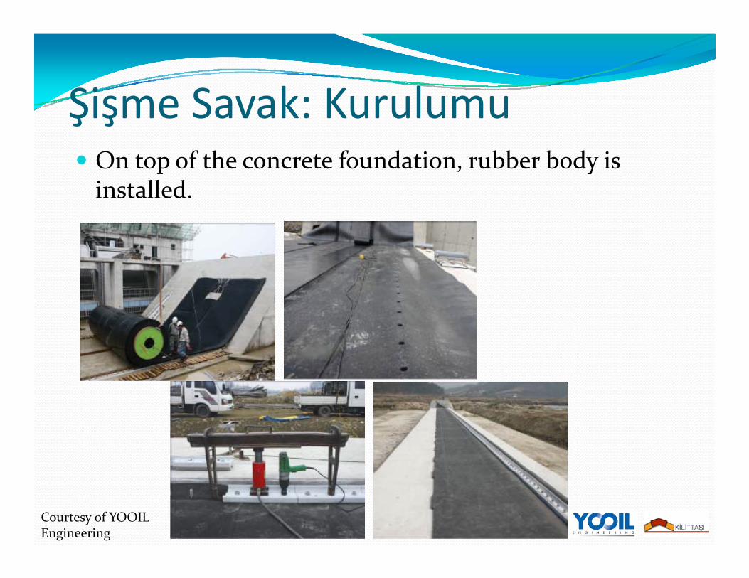
Şişme Savak: KurulumuŞişme Savak: KurulumuOn top of the concrete foundation, rubber body is
ll dinstalled.
Courtesy of YOOIL Engineering

Şişme Savak: KurulumuŞişme Savak: KurulumuControl room and Scada system is installed.
Courtesy of YOOIL Engineering
RereferenceRereferenceYOOIL Engineering
has more than 150 application in South KoreaAlso manufactured and installed rubber dams for water projects in Canada and Philippines projects in Canada and Philippines.
2010 and 2011, 8 new rubber dam will be delivered to Canada

Contact InformationContact InformationKİLİTTAŞI Müh. Müş. İnş. Ltd
www.kilittasi.com.trCeyhun Atuf Kansu Cad. No: 152/15 Cevizlidere/Balgat AnkaraAnkaraTel: +90 312 472 77 67Fax: + 90 312 472 77 68Fax: + 90 312 472 77 68
YOOIL Engineeringwww.yooileng.co.kry g

Courtesy of YOOIL Engineering

CloudWorks Upper Stave RiverCloudWorks Upper Stave River Rubber Dam by YOOIL
Engineering(3mH x 24mL)(3mH x 24mL)
(Sept. 2009)
-PETER KIEWIT Sons. Co.Knight Piesold-Knight Piesold
-YOOIL Rubberdam Engineering

Cloudworks Upper Stave River R bb d I t ll tiRubberdam Installation
2

Cloudworks Upper Stave River Rubberdam InstallationRubberdam Installation
3

Cloudworks Upper Stave River Rubberdam Installation
4

Cloudworks Upper Stave River Rubberdam Installation
5

CloudWorks Upper Stave River
Cleaning for Rubberdam Installation
6

Concrete Slab for Rubberdam Installation
7

CloudWorks Upper Stave River
8Concrete Slab for
Rubberdam Installation

Unpacking of Rolled Rubber sheet
9Cloudworks Upper Stave River
Rubberdam Installation

Cloudworks Upper Stave River Rubberdam Installation
(3mH x 24mL)(3mH x 24mL)
Rubber Sheet Lifting
10

Laying down the Rubber Sheety g
11

Rubber Sheet Lifting3mH x 24mL
12

Cloudworks Upper Stave River ppRubber Sheet Rolling
13
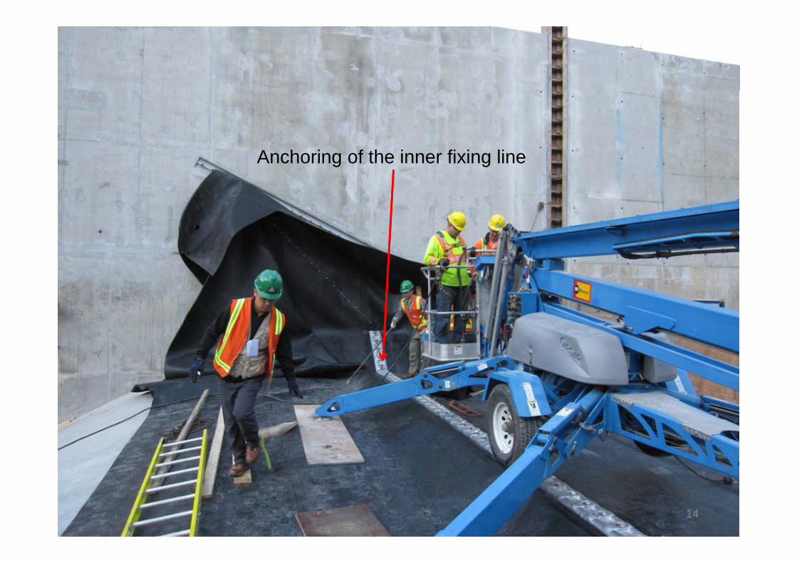
Anchoring of the inner fixing lineAnchoring of the inner fixing line
14

15
Anchoring of the inner fixing line

Rubberdam InstallationRubberdam InstallationOn Vertical 90 Degree
Abutment
16

Cloudworks Upper Stave RiverCloudworks Upper Stave River Rubberdam Installation
17

Anchoring of Outer Fixing Line with rust-free Fiber Glass
Cl i l tClamping plates
18

Anchoring of Outer Fixing Line with rust-free Fiber Glass
Clamping plates
19

Anchoring of Outer Fixing Line with rust-free Fiber Glass
20UpperCloud Stave Rubberdam Installation
with rust-free Fiber Glass Clamping plates

Anchoring of Outer Fixing Line with rust-free Fiber Glass
21UpperCloud Stave Rubberdam Installation
Clamping plates

22YOOIL and KIEWIT Crews

Fully Inflated RubberDamy
23

Fully Inflated RubberDam
24