CCIE Security Lab Workbook Volume I Version 3 - Lagout Security... · The following publication,...
157
CCIE Security Lab Workbook Volume I Version 3.0 Copyright © 2007 Internetwork Expert www.InternetworkExpert.com - i - Copyright Information Copyright © 2003 - 2007 Internetwork Expert, Inc. All rights reserved. The following publication, CCIE Security Lab Workbook Volume I, was developed by Internetwork Expert, Inc. All rights reserved. No part of this publication may be reproduced or distributed in any form or by any means without the prior written permission of Internetwork Expert, Inc. Cisco®, Cisco® Systems, CCIE, and Cisco Certified Internetwork Expert, are registered trademarks of Cisco® Systems, Inc. and/or its affiliates in the U.S. and certain countries. All other products and company names are the trademarks, registered trademarks, and service marks of the respective owners. Throughout this manual, Internetwork Expert, Inc. has used its best efforts to distinguish proprietary trademarks from descriptive names by following the capitalization styles used by the manufacturer.
Transcript of CCIE Security Lab Workbook Volume I Version 3 - Lagout Security... · The following publication,...

CCIE Security Lab Workbook Volume I Version 3.0
Copyright © 2007 Internetwork Expert www.InternetworkExpert.com- i -
Copyright Information Copyright © 2003 2007 Internetwork Expert, Inc. All rights reserved.
The following publication, CCIE Security Lab Workbook Volume I, was developed by Internetwork Expert, Inc. All rights reserved. No part of this publication may be reproduced or distributed in any form or by any means without the prior written permission of Internetwork Expert, Inc.
Cisco®, Cisco® Systems, CCIE, and Cisco Certified Internetwork Expert, are registered trademarks of Cisco® Systems, Inc. and/or its affiliates in the U.S. and certain countries. All other products and company names are the trademarks, registered trademarks, and service marks of the respective owners. Throughout this manual, Internetwork Expert, Inc. has used its best efforts to distinguish proprietary trademarks from descriptive names by following the capitalization styles used by the manufacturer.
CCIE Security Lab Workbook Volume I Version 3.0
Copyright © 2007 Internetwork Expert www.InternetworkExpert.com- ii -
Disclaimer
The following publication, CCIE Security Lab Workbook Volume I, is designed to assist candidates in the preparation for Cisco Systems’ CCIE Routing & Switching Lab exam. While every effort has been made to ensure that all material is as complete and accurate as possible, the enclosed material is presented on an “as is” basis. Neither the authors nor Internetwork Expert, Inc. assume any liability or responsibility to any person or entity with respect to loss or damages incurred from the information contained in this workbook.
This workbook was developed by Internetwork Expert, Inc. and is an original work of the aforementioned authors. Any similarities between material presented in this workbook and actual CCIETM lab material is completely coincidental.

CCIE Security Lab Workbook Volume I Version 3.0
Copyright © 2007 Internetwork Expert www.InternetworkExpert.com- iii -
Table of Contents
PIX/ASA FIREWALL.......................................................................... 1BASIC CONFIGURATION........................................................................................1
Configuring VLANs and IP Addressing ..........................................................1Configuring and Authenticating RIP...............................................................7Configuring and Authenticating OSPF .........................................................10Redistribution, Summarization and Route Filtering......................................14
ACCESS CONTROL.............................................................................................19Common Configuration................................................................................19Filtering with IP Access Lists .......................................................................22Using Object Groups ...................................................................................26Administrative Access Management............................................................31ICMP Traffic Management...........................................................................34Configuring Filtering Services ......................................................................37
CONFIGURING NAT ...........................................................................................39Dynamic NAT and PAT................................................................................39Static NAT and PAT.....................................................................................43Dynamic Policy NAT ....................................................................................46Static Policy NAT and PAT ..........................................................................48Identity NAT and NAT Exemption ................................................................51Outside Dynamic NAT .................................................................................53DNS Doctoring with Alias.............................................................................56DNS Doctoring with Static............................................................................60Same Security Traffic and NAT ...................................................................64
ADVANCED FIREWALL ........................................................................................69Firewall Contexts Configuration ...................................................................69Administrative Context and Resource Management....................................79Active Stateful Failover with Failover Interface ............................................83Active Stateful Failover with Failover Interface ............................................89Monitoring Interfaces with Active/Active Failover.........................................99Filtering with L2 Transparent Firewall ........................................................104ARP Inspection with Transparent Firewall .................................................107Filtering Non-IP Traffic with L2 Transparent FW........................................109Handling Fragmented Traffic .....................................................................111Handling Some Application Issues ............................................................113BGP Through the PIX/ASA Firewall...........................................................115Multicast Routing across the PIX/ASA Firewall..........................................118System Monitoring .....................................................................................123DHCP Server .............................................................................................126
MODULAR POLICY FRAMEWORK .......................................................................129HTTP Inspection with MPF ........................................................................129Advanced FTP Inspection..........................................................................133Advanced ESMTP Inspection ....................................................................138

CCIE Security Lab Workbook Volume I Version 3.0
Copyright © 2007 Internetwork Expert www.InternetworkExpert.com- iv -
Authenticating BGP Session Through the Firewall ....................................141Implementing Traffic Policing.....................................................................143Implementing Low Latency Queueing........................................................145TCP Normalization.....................................................................................148Management Traffic and MPF ...................................................................150ICMP Inspection Engine ............................................................................152

CCIE Security Lab Workbook Volume I Version 3.0
Copyright © 2007 Internetwork Expert www.InternetworkExpert.com- 1 -
PIX/ASA Firewall
Basic Configuration
Configuring VLANs and IP Addressing
Objective: Perform initial configuration of the ASA firewall.
Directions
Pre-configure devices as follows:
o Create VLANs 100,120,121,124 on SW1 and SW2. o Configure ports Fa0/21 – 23 between SW1 and SW2 as 802.1q
trunks.o Configure the switchports for R1, R2, R3, R4, AAA/CA Server
in respective VLANs as per the diagram.

CCIE Security Lab Workbook Volume I Version 3.0
Copyright © 2007 Internetwork Expert www.InternetworkExpert.com- 2 -
o Configure the switchports for the E0/1 (inside) and E0/0 (outside) interfaces of the ASA1 into respective VLANs.
o Configure the switchport for the E0/2 interface of the ASA1 as 802.1q trunk.
Basic ASA initialization includes configuring & activating interfaces/subinterfaces, as well as assigning security-levels and IP addresses.
Configure the ASA1 interface E 0/0 as follows:
o User nameif “outside”. o Use security-level 0.
Configure the ASA1 interface E 0/1 as follows:
o User nameif “inside”. o Use security-level 100.
Configure the ASA1 subinterface E 0/2.120 as follows:
o Use VLAN id 120. o Use nameif “dmz1”. o Use security-level 75.
Configure the ASA1 subinterface E 0/2.124 as follows:
o Use VLAN id 124. o Use nameif “dmz2”. o Use security-level 50.
Configure interface IP addressing as per the diagram.
Final Configuration
SW1:vlan 100,120,121,124 !interface Fa 0/1 switchport host switchport access vlan 121 !interface Fa 0/2 switchport host switchport access vlan 100 !interface Fa 0/3 switchport host switchport access vlan 100 !interface Fa 0/4

CCIE Security Lab Workbook Volume I Version 3.0
Copyright © 2007 Internetwork Expert www.InternetworkExpert.com- 3 -
switchport host switchport access vlan 124 !interface Fa 0/13 switchport host switchport access vlan 121 !interface Fa 0/20 switchport hostswitchport access vlan 120 !! trunks!interface range fa 0/21 - 23 switchport trunk encapsulation dot1q switchport mode dynamic desirable
SW2:vlan 100,120,121,124 !interface Fa 0/12 switchport host switchport access vlan 100 !interface Fa 0/13 switchport trunk encapsulation dot1q switchport mode trunk !! trunks!interface range fa 0/21 - 23 switchport trunk encapsulation dot1q switchport mode dynamic auto
ASA1:interface Ethernet0/0 nameif outside security-level 0 ip address 136.1.0.12 255.255.255.0 no shutdown !interface Ethernet0/1 nameif inside security-level 100 ip address 136.1.121.12 255.255.255.0 no shutdown !interface Ethernet0/2 no nameif no security-level no ip address no shutdown !interface Ethernet0/2.120 vlan 120 nameif dmz1 security-level 75 ip address 10.0.0.12 255.255.255.0 no shutdown !interface Ethernet0/2.124 vlan 124 nameif dmz2

CCIE Security Lab Workbook Volume I Version 3.0
Copyright © 2007 Internetwork Expert www.InternetworkExpert.com- 4 -
security-level 50 ip address 136.1.124.12 255.255.255.0 no shutdown
R1:interface Eth 0/0 no shutdown ip address 136.1.121.1 255.255.255.0 !R2:interface Eth 0/0 no shutdown ip address 136.1.0.2 255.255.255.0
R3:interface Eth 0/0 no shutdown ip address 136.1.0.3 255.255.255.0
R4:interface Eth 0/0 no shutdown ip address 136.1.124.4 255.255.255.0
Verification
SW1#show vlan brief | ex unsup
VLAN Name Status Ports ---- -------------------------------- --------- ------------------------------- 1 default active Fa0/5, Fa0/6, Fa0/7, Fa0/8 Fa0/9, Fa0/10, Fa0/11, Fa0/12 Fa0/14, Fa0/15, Fa0/16, Fa0/17 Fa0/18, Fa0/19, Fa0/24, Gi0/1 Gi0/2 100 VLAN0100 active Fa0/2, Fa0/3 120 VLAN0120 active Fa0/20 121 VLAN0121 active Fa0/1, Fa0/13 124 VLAN0124 active Fa0/4
SW1#show int trunk
Port Mode Encapsulation Status Native vlan Fa0/21 desirable 802.1q trunking 1 Fa0/22 desirable 802.1q trunking 1 Fa0/23 desirable 802.1q trunking 1
Port Vlans allowed on trunk Fa0/21 1-4094 Fa0/22 1-4094 Fa0/23 1-4094
Port Vlans allowed and active in management domain Fa0/21 1,100,120-121,124 Fa0/22 1,100,120-121,124 Fa0/23 1,100,120-121,124
Port Vlans in spanning tree forwarding state and not pruned Fa0/21 1,100,120-121,124 Fa0/22 1,100,120-121,124 Fa0/23 1,100,120-121,124

CCIE Security Lab Workbook Volume I Version 3.0
Copyright © 2007 Internetwork Expert www.InternetworkExpert.com- 5 -
SW2#show interfaces trunk
Port Mode Encapsulation Status Native vlan Fa0/13 on 802.1q trunking 1 Fa0/21 auto 802.1q trunking 1 Fa0/22 auto 802.1q trunking 1 Fa0/23 auto 802.1q trunking 1
Port Vlans allowed on trunk Fa0/13 1-4094 Fa0/21 1-4094 Fa0/22 1-4094 Fa0/23 1-4094
Port Vlans allowed and active in management domain Fa0/13 1,100,120-121,124 Fa0/21 1,100,120-121,124 Fa0/22 1,100,120-121,124 Fa0/23 1,100,120-121,124
Port Vlans in spanning tree forwarding state and not pruned Fa0/13 1,100,120-121,124 Fa0/21 1,100,120-121,124 Fa0/22 none
Port Vlans in spanning tree forwarding state and not pruned Fa0/23 none
ASA1# show nameifInterface Name Security Ethernet0/0 outside 0 Ethernet0/1 inside 100 Ethernet0/2.120 dmz1 75 Ethernet0/2.124 dmz2 50
ASA1# ping 136.1.121.1Type escape sequence to abort. Sending 5, 100-byte ICMP Echos to 136.1.121.1, timeout is 2 seconds: !!!!!Success rate is 100 percent (5/5), round-trip min/avg/max = 1/2/10 ms
ASA1# ping 10.0.0.100Type escape sequence to abort. Sending 5, 100-byte ICMP Echos to 10.0.0.100, timeout is 2 seconds: !!!!!Success rate is 100 percent (5/5), round-trip min/avg/max = 1/1/1 ms
ASA1# ping 136.1.0.2Type escape sequence to abort. Sending 5, 100-byte ICMP Echos to 136.1.0.2, timeout is 2 seconds: !!!!!Success rate is 100 percent (5/5), round-trip min/avg/max = 1/2/10 ms
ASA1# ping 136.1.0.3Type escape sequence to abort. Sending 5, 100-byte ICMP Echos to 136.1.0.3, timeout is 2 seconds: !!!!!Success rate is 100 percent (5/5), round-trip min/avg/max = 1/2/10 ms
ASA1# ping 136.1.124.4Type escape sequence to abort. Sending 5, 100-byte ICMP Echos to 136.1.124.4, timeout is 2 seconds:

CCIE Security Lab Workbook Volume I Version 3.0
Copyright © 2007 Internetwork Expert www.InternetworkExpert.com- 6 -
!!!!!Success rate is 100 percent (5/5), round-trip min/avg/max = 1/1/1 ms
Further Reading
Configuring VLANs: Configuring VLAN TrunksConfiguring Interface Parameters Configuring Ethernet Settings and Subinterfaces

CCIE Security Lab Workbook Volume I Version 3.0
Copyright © 2007 Internetwork Expert www.InternetworkExpert.com- 7 -
Configuring and Authenticating RIP
Objective: Configure RIP routing process on the ASA firewall
RIPv2
RIPv2
R2
R1
R3
ASA1
R4
AAA/CA Server
OutsideInside
DMZ1
DMZ2
E 0/0
E 0/0
E 0/0
E 0/0
Directions
Configure the devices as per the “PIX/ASA Firewall/Basic Configuration” scenario “Configuring VLANs and IP Addressing”.
ASA has capability to use RIP as routing protocol. Configuration is very similar to IOS RIP configuration process.
Create RIP routing process on the ASA firewall. Enable RIP for networks 10.0.0.0/8 and 136.1.0.0/16. Explicitly configure RIP version 2 and disable auto-summary. Configure all interfaces except for “Inside” and “DMZ1” as passive. Configure RIPv2 on R1, use network 136.1.0.0/16. Configure MD5 authentication on interface Inside. Configure R1 respectively. Use keystring “CISCO”.

CCIE Security Lab Workbook Volume I Version 3.0
Copyright © 2007 Internetwork Expert www.InternetworkExpert.com- 8 -
Final Configuration
ASA1:!! RIP process configuration!router rip network 10.0.0.0 network 136.1.0.0 passive-interface default no passive-interface inside no passive-interface dmz1 version 2 no auto-summary
!! MD5 Authentication on Inside !interface Ethernet0/1 rip authentication mode md5 rip authentication key CISCO key_id 1
R1:router rip version 2 no auto-summary network 136.1.0.0 !! MD5 Authentication!key chain RIP key 1 key-string CISCO !interface Ethernet 0/0 ip rip authentication mode md5 ip rip authentication key-chain RIP !
Verification
R1#show ip protocols Routing Protocol is "rip" Sending updates every 30 seconds Invalid after 180 seconds, hold down 180, flushed after 240 Outgoing update filter list for all interfaces is not set Incoming update filter list for all interfaces is not set Redistributing: rip Default version control: send version 2, receive version 2 Interface Send Recv Triggered RIP Key-chain Ethernet0/0 2 2 RIP Automatic network summarization is not in effect Maximum path: 4 Routing for Networks: 136.1.0.0 Routing Information Sources: Gateway Distance Last Update Distance: (default is 120)

CCIE Security Lab Workbook Volume I Version 3.0
Copyright © 2007 Internetwork Expert www.InternetworkExpert.com- 9 -
ASA1# debug rip ASA1#RIP: sending v2 update to 224.0.0.9 via inside (136.1.121.12) RIP: build update entries 10.0.0.0 255.255.255.0 via 0.0.0.0, metric 1, tag 0 136.1.0.0 255.255.255.0 via 0.0.0.0, metric 1, tag 0 136.1.124.0 255.255.255.0 via 0.0.0.0, metric 1, tag 0 RIP: Update contains 3 routes RIP: Update queued RIP: sending v2 update to 224.0.0.9 via dmz1 (10.0.0.12) RIP: build update entries 136.1.0.0 255.255.255.0 via 0.0.0.0, metric 1, tag 0 136.1.121.0 255.255.255.0 via 0.0.0.0, metric 1, tag 0 136.1.124.0 255.255.255.0 via 0.0.0.0, metric 1, tag 0 RIP: Update contains 3 routes RIP: Update queued RIP: Update sent via inside rip-len:112 RIP: Update sent via dmz1 rip-len:72
R1#debug ip rip RIP protocol debugging is on R1#*Mar 21 11:59:08.454: RIP: sending v2 update to 224.0.0.9 via Ethernet0/0 (136.1.121.1)*Mar 21 11:59:08.454: RIP: build update entries - suppressing null update *Mar 21 11:59:11.215: RIP: received packet with MD5 authentication *Mar 21 11:59:11.215: RIP: received v2 update from 136.1.121.12 on Ethernet0/0 *Mar 21 11:59:11.215: 10.0.0.0/24 via 0.0.0.0 in 1 hops *Mar 21 11:59:11.215: 136.1.0.0/24 via 0.0.0.0 in 1 hops *Mar 21 11:59:11.219: 136.1.124.0/24 via 0.0.0.0 in 1 hops
R1#sh ip route rip 136.1.0.0/24 is subnetted, 3 subnets R 136.1.0.0 [120/1] via 136.1.121.12, 00:00:23, Ethernet0/0 R 136.1.124.0 [120/1] via 136.1.121.12, 00:00:23, Ethernet0/0 10.0.0.0/24 is subnetted, 2 subnets R 10.0.0.0 [120/1] via 136.1.121.12, 00:00:23, Ethernet0/0
Further Reading
ASA Command Line Configuration Guide: Configuring RIP
CCIE Security Lab Workbook Volume I Version 3.0
Copyright © 2007 Internetwork Expert www.InternetworkExpert.com- 10 -
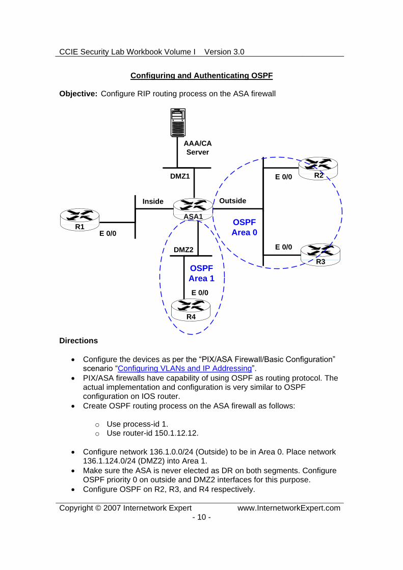
Configuring and Authenticating OSPF
Objective: Configure RIP routing process on the ASA firewall
OSPFArea 0
OSPFArea 1
R2
R1
R3
ASA1
R4
AAA/CA Server
OutsideInside
DMZ1
DMZ2
E 0/0
E 0/0
E 0/0
E 0/0
Directions
Configure the devices as per the “PIX/ASA Firewall/Basic Configuration” scenario “Configuring VLANs and IP Addressing”.
PIX/ASA firewalls have capability of using OSPF as routing protocol. The actual implementation and configuration is very similar to OSPF configuration on IOS router.
Create OSPF routing process on the ASA firewall as follows:
o Use process-id 1. o Use router-id 150.1.12.12.
Configure network 136.1.0.0/24 (Outside) to be in Area 0. Place network 136.1.124.0/24 (DMZ2) into Area 1.
Make sure the ASA is never elected as DR on both segments. Configure OSPF priority 0 on outside and DMZ2 interfaces for this purpose.
Configure OSPF on R2, R3, and R4 respectively.

CCIE Security Lab Workbook Volume I Version 3.0
Copyright © 2007 Internetwork Expert www.InternetworkExpert.com- 11 -
Configure OSPF MD5 authentication on interface DMZ2 as follows:
o Use only interface-level commands. o Configure R4 respectively. o Use keystring “CISCO”.
Configure OSPF Text authentication on interface Outside. Enable authentication globally under the routing process for Area 0. Configure R2 and R3 respectively. Use keystring “CISCO”.
Final Configuration
ASA1:!! OSPF routing process!router ospf 1 network 136.1.0.0 255.255.255.0 area 0 network 136.1.124.0 255.255.255.0 area 1 router-id 150.1.12.12 area 0 authentication !! Authentication for area 1 is configured solely on interface!interface Ethernet0/2.124 ospf message-digest-key 1 md5 CISCO ospf authentication message-digest ospf priority 0 !! Only the auth key is configured at interface level!interface Ethernet0/0 ospf authentication-key CISCO ospf priority 0
R2:router ospf 1 router-id 150.1.2.2 network 136.1.0.0 0.0.0.255 area 0 area 0 authentication !interface Ethernet 0/0 ip ospf authentication-key CISCO
R3:router ospf 1 router-id 150.1.3.3 network 136.1.0.0 0.0.0.255 area 0 area 0 authentication !interface Ethernet 0/0 ip ospf authentication-key CISCO
R4:router ospf 1 router-id 150.1.4.4 network 136.1.124.0 0.0.0.255 area 1

CCIE Security Lab Workbook Volume I Version 3.0
Copyright © 2007 Internetwork Expert www.InternetworkExpert.com- 12 -
!interface Ethernet 0/0 ip ospf authentication message-digest ip ospf message-digest-key 1 md5 CISCO

CCIE Security Lab Workbook Volume I Version 3.0
Copyright © 2007 Internetwork Expert www.InternetworkExpert.com- 13 -
Verification
ASA1# show ospf neighbor
Neighbor ID Pri State Dead Time Address Interface 150.1.2.2 1 FULL/BDR 0:00:38 136.1.0.2 outside 150.1.3.3 1 FULL/DR 0:00:35 136.1.0.3 outside 150.1.4.4 1 FULL/DR 0:00:39 136.1.124.4 dmz2
ASA1# show ospf interface
outside is up, line protocol is up Internet Address 136.1.0.12 mask 255.255.255.0, Area 0 Process ID 1, Router ID 150.1.12.12, Network Type BROADCAST, Cost: 10 Transmit Delay is 1 sec, State DROTHER, Priority 0 Designated Router (ID) 150.1.3.3, Interface address 136.1.0.3 Backup Designated router (ID) 150.1.2.2, Interface address 136.1.0.2 Flush timer for old DR LSA due in 0:00:42 Timer intervals configured, Hello 10, Dead 40, Wait 40, Retransmit 5 Hello due in 0:00:05 Index 1/1, flood queue length 0 Next 0x0(0)/0x0(0) Last flood scan length is 0, maximum is 3 Last flood scan time is 0 msec, maximum is 0 msec Neighbor Count is 2, Adjacent neighbor count is 2 Adjacent with neighbor 150.1.2.2 (Backup Designated Router) Adjacent with neighbor 150.1.3.3 (Designated Router) Suppress hello for 0 neighbor(s) Simple password authentication enabled dmz2 is up, line protocol is up Internet Address 136.1.124.12 mask 255.255.255.0, Area 1 Process ID 1, Router ID 150.1.12.12, Network Type BROADCAST, Cost: 10 Transmit Delay is 1 sec, State DROTHER, Priority 0 Designated Router (ID) 150.1.4.4, Interface address 136.1.124.4 No backup designated router on this network Flush timer for old DR LSA due in 0:00:31 Timer intervals configured, Hello 10, Dead 40, Wait 40, Retransmit 5 Hello due in 0:00:01 Index 1/2, flood queue length 0 Next 0x0(0)/0x0(0) Last flood scan length is 1, maximum is 3 Last flood scan time is 0 msec, maximum is 0 msec Neighbor Count is 1, Adjacent neighbor count is 1 Adjacent with neighbor 150.1.4.4 (Designated Router) Suppress hello for 0 neighbor(s) Message digest authentication enabled Youngest key id is 1
Further Reading
ASA Command Line Configuration Guide: Configuring OSPF

CCIE Security Lab Workbook Volume I Version 3.0
Copyright © 2007 Internetwork Expert www.InternetworkExpert.com- 14 -
Redistribution, Summarization and Route Filtering
Objective: Redistribute between OSPF and RIP. Summarize and filter routes on redistribution.
RIPv2
RIPv2
OSPFArea 0
OSPFArea 1
R2
R1
R3
ASA1
R4
AAA/CA Server
OutsideInside
DMZ1
DMZ2
E 0/0
E 0/0
E 0/0
E 0/0
Lo0: 150.X.2.2/24Lo1: 192.168.1.2/24Lo2: 192.168.3.2/24Lo3: 192.168.5.2/24
Lo0: 150.X.3.3/24
Lo0: 150.X.4.4/24
Lo0: 150.X.1.1/24Lo1: 192.168.10.1/27Lo2: 192.168.10.33/27Lo3: 192.168.10.65/27
Directions
Configure the devices as per the “PIX/ASA Firewall/Basic Configuration” scenario Configuring and Authenticating RIP.
Configure the devices as per the “PIX/ASA Firewall/Basic Configuration” scenario Configuring and Authenticating OSPF.
The goal is to redistribute routes between routing protocols and apply prefix filtering on redistribution.
Add routing prefixes information as follows:
o Create Loopback interfaces on R1 as per diagram. Advertise them into RIP.
o Create Loopback interfaces on R2 as per diagram. Advertise them into OSPF Area 0.
Create Loopback interfaces on R3 and R4 as per diagram. Advertise them into Area 0 and Area 1 respectively. Do not use redistribution when advertising the Loopback networks.
Make sure Loopback networks advertised into OSPF have their network mask preserved. Use OSPF network type point-to-point for this task.
Summarize networks 192.168.1.0/24, 192.168.3.0/24, 192.168.5.0/24 into single prefix, as they are injected into Area 1.
Filter out networks 150.X.2.0/24 and 150.X.3.0/24 from being advertised into Area 1. Use prefix-list and LSA type 3 filter.
Redistribute between OSPF and RIP routing processes.

CCIE Security Lab Workbook Volume I Version 3.0
Copyright © 2007 Internetwork Expert www.InternetworkExpert.com- 15 -
Make sure that R2, R3 and R4 receive only summary prefix for the 192.168.10.0/27, 192.168.10.32/27, 192.168.10.64/27 networks.
Final Configuration
R1:!! Create the Loopbacks!interface Loopback0 ip address 150.1.1.1 255.255.255.0 !interface Loopback1 ip address 192.168.10.1 255.255.255.224 !interface Loopback2 ip address 192.168.10.33 255.255.255.224 !interface Loopback3 ip address 192.168.10.65 255.255.255.224 !! Advertise the Loopbacks!router rip network 150.1.0.0 network 192.168.10.0
R2:!! Create the Loopbacks!interface Loopback0 ip address 150.1.2.2 255.255.255.0 ip ospf network point-to-point !interface Loopback1 ip address 192.168.1.2 255.255.255.0 ip ospf network point-to-point !interface Loopback2 ip address 192.168.3.2 255.255.255.0 ip ospf network point-to-point !interface Loopback3 ip address 192.168.5.2 255.255.255.0 ip ospf network point-to-point !! Advertise the Loopbacks!router ospf 1 network 150.1.2.2 0.0.0.0 area 0 network 192.168.1.2 0.0.0.0 area 0 network 192.168.3.2 0.0.0.0 area 0 network 192.168.5.2 0.0.0.0 area 0
R3:!! Create and advertise the Loopback !interface Loopback0 ip address 150.1.3.3 255.255.255.0

CCIE Security Lab Workbook Volume I Version 3.0
Copyright © 2007 Internetwork Expert www.InternetworkExpert.com- 16 -
ip ospf network point-to-point !router ospf 1 network 150.1.3.3 0.0.0.0 area 0
R4:!! Create and advertise the Loopback!interface Loopback0 ip address 150.1.4.4 255.255.255.0 ip ospf network point-to-point !router ospf 1 network 150.1.4.4 0.0.0.0 area 1
ASA1:!! Summarize Inter-Area routes for R2 Loopbacks 1-3 !router ospf 1 area 0 range 192.168.0.0 255.255.248.0 !! Prefix-list to block the loopbacks of R2 and R3!prefix-list R2_R3_LOOPBACKS seq 5 deny 150.1.2.0/24 prefix-list R2_R3_LOOPBACKS seq 10 deny 150.1.3.0/24 prefix-list R2_R3_LOOPBACKS seq 15 permit 0.0.0.0/0 le 32 !! OSPF:! Apply area-filter!router ospf 1 area 1 filter-list prefix R2_R3_LOOPBACKS in !! Redistribute RIP subnets and apply summarization!router ospf 1 redistribute rip subnets summary-address 192.168.10.0 255.255.255.128 !! RIP:! Redistribute OSPF!router rip redistribute ospf 1 metric 1
Verification
R1#show ip route rip 136.1.0.0/24 is subnetted, 3 subnets R 136.1.0.0 [120/1] via 136.1.121.12, 00:00:13, Ethernet0/0 R 136.1.124.0 [120/1] via 136.1.121.12, 00:00:13, Ethernet0/0 R 192.168.5.0/24 [120/1] via 136.1.121.12, 00:00:13, Ethernet0/0 10.0.0.0/24 is subnetted, 2 subnets R 10.0.0.0 [120/1] via 136.1.121.12, 00:00:13, Ethernet0/0 R 192.168.1.0/24 [120/1] via 136.1.121.12, 00:00:13, Ethernet0/0 150.1.0.0/24 is subnetted, 4 subnets R 150.1.4.0 [120/1] via 136.1.121.12, 00:00:13, Ethernet0/0 R 150.1.3.0 [120/1] via 136.1.121.12, 00:00:13, Ethernet0/0

CCIE Security Lab Workbook Volume I Version 3.0
Copyright © 2007 Internetwork Expert www.InternetworkExpert.com- 17 -
R 150.1.2.0 [120/1] via 136.1.121.12, 00:00:13, Ethernet0/0 R 192.168.3.0/24 [120/1] via 136.1.121.12, 00:00:13, Ethernet0/0
ASA1# show route
Codes: C - connected, S - static, I - IGRP, R - RIP, M - mobile, B - BGP D - EIGRP, EX - EIGRP external, O - OSPF, IA - OSPF inter area N1 - OSPF NSSA external type 1, N2 - OSPF NSSA external type 2 E1 - OSPF external type 1, E2 - OSPF external type 2, E - EGP i - IS-IS, L1 - IS-IS level-1, L2 - IS-IS level-2, ia - IS-IS inter area * - candidate default, U - per-user static route, o - ODR P - periodic downloaded static route
Gateway of last resort is not set
C 136.1.0.0 255.255.255.0 is directly connected, outside C 136.1.121.0 255.255.255.0 is directly connected, inside C 136.1.124.0 255.255.255.0 is directly connected, dmz2 R 192.168.10.64 255.255.255.224 [120/1] via 136.1.121.1, 0:00:06, inside R 192.168.10.32 255.255.255.224 [120/1] via 136.1.121.1, 0:00:06, inside O 192.168.10.0 255.255.255.192 is a summary, 0:00:28, OSPF Unknown Type R 192.168.10.0 255.255.255.224 [120/1] via 136.1.121.1, 0:00:06, inside O 192.168.5.0 255.255.255.0 [110/11] via 136.1.0.2, 0:04:42, outside C 10.0.0.0 255.255.255.0 is directly connected, dmz1 O 192.168.1.0 255.255.255.0 [110/11] via 136.1.0.2, 0:04:42, outside O 150.1.4.0 255.255.255.0 [110/11] via 136.1.124.4, 0:02:10, dmz2 O 150.1.3.0 255.255.255.0 [110/11] via 136.1.0.3, 0:04:42, outside O 150.1.2.0 255.255.255.0 [110/11] via 136.1.0.2, 0:04:42, outside R 150.1.1.0 255.255.255.0 [120/1] via 136.1.121.1, 0:00:06, inside O 192.168.3.0 255.255.255.0 [110/11] via 136.1.0.2, 0:04:45, outside O 192.168.0.0 255.255.248.0 is a summary, 0:04:45
R2#show ip route ospf 136.1.0.0/24 is subnetted, 3 subnets O E2 136.1.121.0 [110/20] via 136.1.0.12, 00:09:29, Ethernet0/0 O IA 136.1.124.0 [110/20] via 136.1.0.12, 00:09:29, Ethernet0/0 192.168.10.0/25 is subnetted, 1 subnets O E2 192.168.10.0 [110/20] via 136.1.0.12, 00:00:03, Ethernet0/0 10.0.0.0/24 is subnetted, 2 subnets O E2 10.0.0.0 [110/20] via 136.1.0.12, 00:09:29, Ethernet0/0 150.1.0.0/24 is subnetted, 4 subnets O IA 150.1.4.0 [110/21] via 136.1.0.12, 00:06:57, Ethernet0/0 O 150.1.3.0 [110/11] via 136.1.0.3, 00:09:29, Ethernet0/0 O E2 150.1.1.0 [110/20] via 136.1.0.12, 00:05:02, Ethernet0/0
R4#show ip route ospf 136.1.0.0/24 is subnetted, 3 subnets O IA 136.1.0.0 [110/20] via 136.1.124.12, 00:07:49, Ethernet0/0 O E2 136.1.121.0 [110/20] via 136.1.124.12, 00:07:49, Ethernet0/0 192.168.10.0/25 is subnetted, 1 subnets O E2 192.168.10.0 [110/20] via 136.1.124.12, 00:00:49, Ethernet0/0 10.0.0.0/24 is subnetted, 2 subnets O E2 10.0.0.0 [110/20] via 136.1.124.12, 00:07:49, Ethernet0/0 150.1.0.0/24 is subnetted, 2 subnets O E2 150.1.1.0 [110/20] via 136.1.124.12, 00:05:54, Ethernet0/0 O IA 192.168.0.0/21 [110/21] via 136.1.124.12, 00:07:49, Ethernet0/0

CCIE Security Lab Workbook Volume I Version 3.0
Copyright © 2007 Internetwork Expert www.InternetworkExpert.com- 18 -
Further Reading
ASA Command Line Configuration Guide: Configuring IP Routing

CCIE Security Lab Workbook Volume I Version 3.0
Copyright © 2007 Internetwork Expert www.InternetworkExpert.com- 19 -
Access Control
Common Configuration
Objective: Perform configuration steps common to traffic filtering tasks.
Directions
Create the necessary VLANs and configure the switch ports respectively as per the diagram.
Configure IP addressing as per the diagram. Configure RIP as routing protocol on all devices.
Final Configuration
ASA1:!! IP addressing!interface Ethernet0/0 no shut nameif outside security-level 0 ip address 136.1.122.12 255.255.255.0!

CCIE Security Lab Workbook Volume I Version 3.0
Copyright © 2007 Internetwork Expert www.InternetworkExpert.com- 20 -
interface Ethernet0/1 no shut nameif inside security-level 100 ip address 136.1.121.12 255.255.255.0!interface Ethernet0/2 no shut nameif dmz security-level 50 ip address 10.0.0.12 255.255.255.0 !! RIP configuration!router rip version 2 no auto-summary network 10.0.0.0 network 136.1.0.0
SW1 & SW2: !! create VLANs and configure trunk links!vlan 120,121,122 !interface range Fa 0/21 - 23 switchport trunk encapsulation dot1q switchport mode trunk no shut
SW1:!! Configure switchports!interface Fa 0/1 switchport host switchport access vlan 121 !interface Fa 0/2 switchport host switchport access vlan 122 !interface Fa 0/13 switchport host switchport access vlan 121 !interface Fa 0/20 switchport host switchport access vlan 120
SW2:!! Configure switchports!interface Fa 0/12 switchport host switchport access vlan 122 !interface Fa 0/13 switchport host switchport access vlan 120

CCIE Security Lab Workbook Volume I Version 3.0
Copyright © 2007 Internetwork Expert www.InternetworkExpert.com- 21 -
R1:interface E 0/0 no shut ip add 136.1.121.1 255.255.255.0 !router rip ver 2 no auto network 136.1.0.0
R2:interface E 0/0 no shut ip add 136.1.122.2 255.255.255.0 !router rip ver 2 no auto network 136.1.0.0
Verification
R1#show ip route rip 136.1.0.0/24 is subnetted, 2 subnets R 136.1.122.0 [120/1] via 136.1.121.12, 00:00:12, Ethernet0/0 10.0.0.0/24 is subnetted, 2 subnets R 10.0.0.0 [120/1] via 136.1.121.12, 00:00:12, Ethernet0/0
R2#show ip route rip 136.1.0.0/24 is subnetted, 2 subnets R 136.1.121.0 [120/1] via 136.1.122.12, 00:00:19, Ethernet0/0 10.0.0.0/24 is subnetted, 2 subnets R 10.0.0.0 [120/1] via 136.1.122.12, 00:00:19, Ethernet0/0

CCIE Security Lab Workbook Volume I Version 3.0
Copyright © 2007 Internetwork Expert www.InternetworkExpert.com- 22 -
Filtering with IP Access Lists
Objective: Configure filtering using an access-list to implement security policy.
ASA1
R1
R2
AAA/CAServer
Inside Outside
DMZ
136.X.122.0/24 VLAN122
R3.1
.2
.100
136.X.121.0/24 VLAN121
10.0.0.0/24 VLAN120
.12 .12
.12
RIPv2
Directions
Configure devices as per the scenario “PIX/ASA Firewall/Access Control” ”Common Configuration”.
Create two accesslist to be applied to outside interface – ingress and egress. Name them OUTSIDE_IN and OUTSIDE_OUT.
Ingress ACL should permit the following:
o Incoming pings (ICMP echo) o Returning pings (ICMP echo-reply) o FTP/HTTP/NTP traffic to AAA/CA server o Returning UNIX-like Traceroute traffic (ICMP time-exceeded, port-
unreachable)
Egress ACL should permit the following:
o Outgoing pings (ICMP echo) o Returning pings (ICMP echo-reply) o Outgoing UNIX-like traceroute (UDP ports 33434 - 33464 by
default)o Outgoing telnet, FTP, HTTP traffic

CCIE Security Lab Workbook Volume I Version 3.0
Copyright © 2007 Internetwork Expert www.InternetworkExpert.com- 23 -
Final Configuration
ASA1:!! Access-Lists definition!access-list OUTSIDE_IN extended permit tcp any host 10.0.0.100 eq www access-list OUTSIDE_IN extended permit tcp any host 10.0.0.100 eq ftp access-list OUTSIDE_IN extended permit udp any host 10.0.0.100 eq ntp access-list OUTSIDE_IN extended permit icmp any any echo access-list OUTSIDE_IN extended permit icmp any any echo-reply access-list OUTSIDE_IN extended permit icmp any any time-exceeded access-list OUTSIDE_IN extended permit icmp any any unreachable !access-list OUTSIDE_OUT extended permit icmp any any echo access-list OUTSIDE_OUT extended permit icmp any any echo-reply access-list OUTSIDE_OUT extended permit udp any any range 33434 33464 access-list OUTSIDE_OUT extended permit tcp any any eq ftp access-list OUTSIDE_OUT extended permit tcp any any eq telnet access-list OUTSIDE_OUT extended permit tcp any any eq www !! Apply the access-lists!access-group OUTSIDE_IN in interface outside access-group OUTSIDE_OUT out interface outside
Verification
R2#ping 10.0.0.100
Type escape sequence to abort. Sending 5, 100-byte ICMP Echos to 10.0.0.100, timeout is 2 seconds: !!!!!Success rate is 100 percent (5/5), round-trip min/avg/max = 1/3/8 ms
R2#ping 136.1.121.1
Type escape sequence to abort. Sending 5, 100-byte ICMP Echos to 136.1.121.1, timeout is 2 seconds: !!!!!Success rate is 100 percent (5/5), round-trip min/avg/max = 1/3/4 ms
R2#telnet 10.0.0.100 80Trying 10.0.0.100, 80 ... Open get / http/1.1
HTTP/1.1 400 Bad Request Server: Microsoft-IIS/5.0 Date: Sat, 06 Jan 2007 11:22:27 GMT Content-Type: text/html Content-Length: 87
<html><head><title>Error</title></head><body>The parameter is incorrect. </body></html>[Connection to 10.0.0.100 closed by foreign host]
R2#telnet 10.0.0.100 21Trying 10.0.0.100, 21 ... Open

CCIE Security Lab Workbook Volume I Version 3.0
Copyright © 2007 Internetwork Expert www.InternetworkExpert.com- 24 -
220 IESERVER1 Microsoft FTP Service (Version 5.0).
R2#disc 1Closing connection to 10.0.0.100 [confirm]
R2#telnet 10.0.0.100 80 Trying 10.0.0.100, 80 ... Open get / http/1.1
HTTP/1.1 400 Bad Request Server: Microsoft-IIS/5.0 Date: Sat, 06 Jan 2007 11:22:27 GMT Content-Type: text/html Content-Length: 87
<html><head><title>Error</title></head><body>The parameter is incorrect. </body></html>[Connection to 10.0.0.100 closed by foreign host] R2#telnet 10.0.0.100 21Trying 10.0.0.100, 21 ... Open 220 IESERVER1 Microsoft FTP Service (Version 5.0).
R2#disc 1Closing connection to 10.0.0.100 [confirm]
R2#telnet 10.0.0.100 25Trying 10.0.0.100, 25 ...% Connection timed out; remote host not responding
R1#telnet 136.1.122.2Trying 136.1.122.2 ... Open
User Access Verification
Password:R2>
R1#ping 136.1.122.2
Type escape sequence to abort. Sending 5, 100-byte ICMP Echos to 136.1.122.2, timeout is 2 seconds: !!!!!Success rate is 100 percent (5/5), round-trip min/avg/max = 1/2/4 ms
R1#ping 10.0.0.100
Type escape sequence to abort. Sending 5, 100-byte ICMP Echos to 10.0.0.100, timeout is 2 seconds: .....Success rate is 0 percent (0/5)
R1#telnet 10.0.0.100 80Trying 10.0.0.100, 80 ... Open get / http/1.1.
HTTP/1.1 400 Bad Request Server: Microsoft-IIS/5.0 Date: Sat, 06 Jan 2007 11:25:59 GMT Content-Type: text/html Content-Length: 87
<html><head><title>Error</title></head><body>The parameter is incorrect.

CCIE Security Lab Workbook Volume I Version 3.0
Copyright © 2007 Internetwork Expert www.InternetworkExpert.com- 25 -
</body></html>[Connection to 10.0.0.100 closed by foreign host]
R1#traceroute 136.1.122.2
Type escape sequence to abort. Tracing the route to 136.1.122.2
1 136.1.122.2 0 msec * 0 msec
ASA1# show access-list access-list cached ACL log flows: total 0, denied 0 (deny-flow-max 4096) alert-interval 300 access-list OUTSIDE_IN; 7 elements access-list OUTSIDE_IN line 1 extended permit tcp any host 10.0.0.100 eq www (hitcnt=1) 0x59f08b76access-list OUTSIDE_IN line 2 extended permit tcp any host 10.0.0.100 eq ftp (hitcnt=1) 0x8997bedfaccess-list OUTSIDE_IN line 3 extended permit udp any host 10.0.0.100 eq ntp (hitcnt=0) 0x8189f120access-list OUTSIDE_IN line 4 extended permit icmp any any echo-reply (hitcnt=10) 0xc857b49eaccess-list OUTSIDE_IN line 5 extended permit icmp any any time-exceeded (hitcnt=0) 0xc3b80daccess-list OUTSIDE_IN line 6 extended permit icmp any any unreachable (hitcnt=5) 0xec6c9a23access-list OUTSIDE_IN line 7 extended permit icmp any any echo (hitcnt=70) 0x869bdf05access-list OUTSIDE_OUT; 6 elements access-list OUTSIDE_OUT line 1 extended permit icmp any any echo (hitcnt=10) 0x4006da3faccess-list OUTSIDE_OUT line 2 extended permit udp any any range 33434 33464 (hitcnt=7) 0xde5f72eeaccess-list OUTSIDE_OUT line 3 extended permit tcp any any eq ftp (hitcnt=0) 0xf47b788access-list OUTSIDE_OUT line 4 extended permit tcp any any eq telnet (hitcnt=3) 0x2be5bbfeaccess-list OUTSIDE_OUT line 5 extended permit tcp any any eq www (hitcnt=0) 0x8a4b160eaccess-list OUTSIDE_OUT line 6 extended permit icmp any any echo-reply (hitcnt=15) 0xd6d9967
Further Reading
Identifying Traffic with Access Lists

CCIE Security Lab Workbook Volume I Version 3.0
Copyright © 2007 Internetwork Expert www.InternetworkExpert.com- 26 -
Using Object Groups
Objective: Simplify access-control policy using object groups.
ASA1
R1
R2
AAA/CAServer
Inside Outside
DMZ
136.X.122.0/24 VLAN122
R3.1
.2
.100
136.X.121.0/24 VLAN121
10.0.0.0/24 VLAN120
.12 .12
.12
RIPv2
Directions
Configure devices as per the scenario “PIX/ASA Firewall/Access Control” ”Common Configuration”.
PIX/ASA firewall has concept of object groups. Group is a collection of similar objects (IP addresses, Ports, ICMP types) that could be used in access-list for compact and scalable configuration.
Create object-group named SERVERS of type network-object. Add host 10.0.0.100 to it.
Create object-group named ROUTERS of type network-object. Add network 136.1.121.0/24 to it.
Create object-group named COMMON_ICMP of type icmp. Add the following ICMP types:
o “echo” and “echoreply” o “timeexceeded” and “unreachable”
Create object-group named TRC_PORTS of type service. Add a range of UDP ports 33434-33464 to it.
Create object-group named SERVER_PORTS of type service. Add TCP ports 80, 21 to it.
CCIE Security Lab Workbook Volume I Version 3.0
Copyright © 2007 Internetwork Expert www.InternetworkExpert.com- 27 -
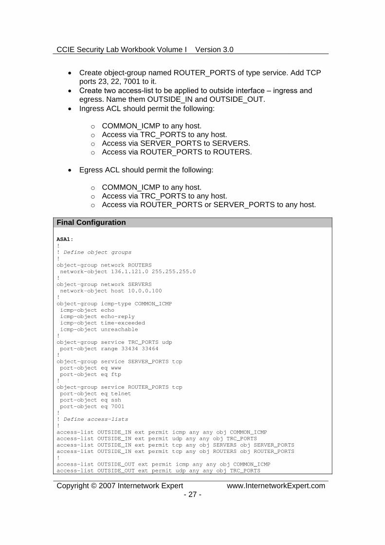
Create object-group named ROUTER_PORTS of type service. Add TCP ports 23, 22, 7001 to it.
Create two accesslist to be applied to outside interface – ingress and egress. Name them OUTSIDE_IN and OUTSIDE_OUT.
Ingress ACL should permit the following:
o COMMON_ICMP to any host. o Access via TRC_PORTS to any host.o Access via SERVER_PORTS to SERVERS. o Access via ROUTER_PORTS to ROUTERS.
Egress ACL should permit the following:
o COMMON_ICMP to any host. o Access via TRC_PORTS to any host. o Access via ROUTER_PORTS or SERVER_PORTS to any host.
Final Configuration
ASA1:!! Define object groups!object-group network ROUTERS network-object 136.1.121.0 255.255.255.0 !object-group network SERVERS network-object host 10.0.0.100 !object-group icmp-type COMMON_ICMP icmp-object echo icmp-object echo-reply icmp-object time-exceeded icmp-object unreachable !object-group service TRC_PORTS udp port-object range 33434 33464 !object-group service SERVER_PORTS tcp port-object eq www port-object eq ftp !object-group service ROUTER_PORTS tcp port-object eq telnet port-object eq ssh port-object eq 7001 !! Define access-lists!access-list OUTSIDE_IN ext permit icmp any any obj COMMON_ICMP access-list OUTSIDE_IN ext permit udp any any obj TRC_PORTS access-list OUTSIDE_IN ext permit tcp any obj SERVERS obj SERVER_PORTS access-list OUTSIDE_IN ext permit tcp any obj ROUTERS obj ROUTER_PORTS !access-list OUTSIDE_OUT ext permit icmp any any obj COMMON_ICMP access-list OUTSIDE_OUT ext permit udp any any obj TRC_PORTS

CCIE Security Lab Workbook Volume I Version 3.0
Copyright © 2007 Internetwork Expert www.InternetworkExpert.com- 28 -
access-list OUTSIDE_IN ext permit tcp any any obj SERVER_PORTS access-list OUTSIDE_IN ext permit tcp any any obj ROUTER_PORTS !! Apply the access-lists!access-group OUTSIDE_IN in interface outside access-group OUTSIDE_OUT out interface outside
Verification
R1#ping 136.1.122.2
Type escape sequence to abort. Sending 5, 100-byte ICMP Echos to 136.1.122.2, timeout is 2 seconds: !!!!!Success rate is 100 percent (5/5), round-trip min/avg/max = 4/4/4 ms
R1#trace 136.1.122.2
Type escape sequence to abort. Tracing the route to 136.1.122.2
1 136.1.122.2 4 msec * 0 msec R1#
R2#trace 136.1.121.1
Type escape sequence to abort. Tracing the route to 136.1.121.1
1 136.1.121.1 4 msec * 0 msec
R2#ping 136.1.121.1
Type escape sequence to abort. Sending 5, 100-byte ICMP Echos to 136.1.121.1, timeout is 2 seconds: !!!!!Success rate is 100 percent (5/5), round-trip min/avg/max = 1/2/4 ms
R2#ping 10.0.0.100
Type escape sequence to abort. Sending 5, 100-byte ICMP Echos to 10.0.0.100, timeout is 2 seconds: !!!!!Success rate is 100 percent (5/5), round-trip min/avg/max = 1/2/4 ms
R2#telnet 136.1.121.1Trying 136.1.121.1 ... Open
Password required, but none set
[Connection to 136.1.121.1 closed by foreign host]
R2#telnet 10.0.0.100 80 Trying 10.0.0.100, 80 ... Open get / http/1.1
HTTP/1.1 400 Bad Request Server: Microsoft-IIS/5.0
CCIE Security Lab Workbook Volume I Version 3.0
Copyright © 2007 Internetwork Expert www.InternetworkExpert.com- 29 -
Date: Sun, 07 Jan 2007 08:16:32 GMT Content-Type: text/html Content-Length: 87
<html><head><title>Error</title></head><body>The parameter is incorrect. </body></html>[Connection to 10.0.0.100 closed by foreign host]
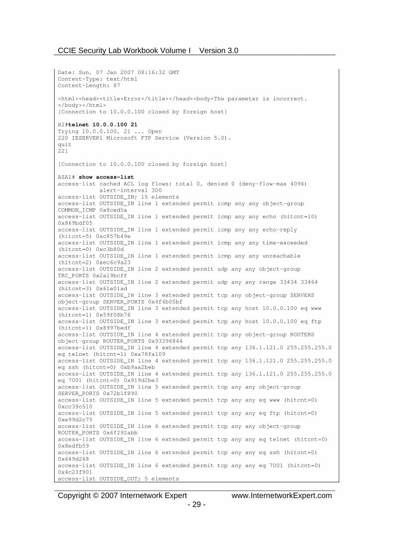
R2#telnet 10.0.0.100 21Trying 10.0.0.100, 21 ... Open 220 IESERVER1 Microsoft FTP Service (Version 5.0). quit221
[Connection to 10.0.0.100 closed by foreign host]
ASA1# show access-list access-list cached ACL log flows: total 0, denied 0 (deny-flow-max 4096) alert-interval 300 access-list OUTSIDE_IN; 15 elements access-list OUTSIDE_IN line 1 extended permit icmp any any object-group COMMON_ICMP 0x8ced5aaccess-list OUTSIDE_IN line 1 extended permit icmp any any echo (hitcnt=10) 0x869bdf05access-list OUTSIDE_IN line 1 extended permit icmp any any echo-reply (hitcnt=5) 0xc857b49eaccess-list OUTSIDE_IN line 1 extended permit icmp any any time-exceeded (hitcnt=0) 0xc3b80daccess-list OUTSIDE_IN line 1 extended permit icmp any any unreachable (hitcnt=2) 0xec6c9a23access-list OUTSIDE_IN line 2 extended permit udp any any object-group TRC_PORTS 0x2a19bcffaccess-list OUTSIDE_IN line 2 extended permit udp any any range 33434 33464 (hitcnt=3) 0x61e01adaccess-list OUTSIDE_IN line 3 extended permit tcp any object-group SERVERS object-group SERVER_PORTS 0x4f4b05bfaccess-list OUTSIDE_IN line 3 extended permit tcp any host 10.0.0.100 eq www (hitcnt=1) 0x59f08b76access-list OUTSIDE_IN line 3 extended permit tcp any host 10.0.0.100 eq ftp (hitcnt=1) 0x8997bedfaccess-list OUTSIDE_IN line 4 extended permit tcp any object-group ROUTERS object-group ROUTER_PORTS 0x93396844access-list OUTSIDE_IN line 4 extended permit tcp any 136.1.121.0 255.255.255.0 eq telnet (hitcnt=1) 0xa78fa109access-list OUTSIDE_IN line 4 extended permit tcp any 136.1.121.0 255.255.255.0 eq ssh (hitcnt=0) 0xb9aa2bebaccess-list OUTSIDE_IN line 4 extended permit tcp any 136.1.121.0 255.255.255.0 eq 7001 (hitcnt=0) 0x919d2be3access-list OUTSIDE_IN line 5 extended permit tcp any any object-group SERVER_PORTS 0x72b1f890access-list OUTSIDE_IN line 5 extended permit tcp any any eq www (hitcnt=0) 0xcc39c510access-list OUTSIDE_IN line 5 extended permit tcp any any eq ftp (hitcnt=0) 0xe99d2c75access-list OUTSIDE_IN line 6 extended permit tcp any any object-group ROUTER_PORTS 0x6f292abbaccess-list OUTSIDE_IN line 6 extended permit tcp any any eq telnet (hitcnt=0) 0x8edfb59access-list OUTSIDE_IN line 6 extended permit tcp any any eq ssh (hitcnt=0) 0x649d268access-list OUTSIDE_IN line 6 extended permit tcp any any eq 7001 (hitcnt=0) 0x4c23f901access-list OUTSIDE_OUT; 5 elements

CCIE Security Lab Workbook Volume I Version 3.0
Copyright © 2007 Internetwork Expert www.InternetworkExpert.com- 30 -
access-list OUTSIDE_OUT line 1 extended permit icmp any any object-group COMMON_ICMP 0x19df4a15access-list OUTSIDE_OUT line 1 extended permit icmp any any echo (hitcnt=5) 0x4006da3faccess-list OUTSIDE_OUT line 1 extended permit icmp any any echo-reply (hitcnt=10) 0xd6d9967access-list OUTSIDE_OUT line 1 extended permit icmp any any time-exceeded (hitcnt=0) 0x1c223353access-list OUTSIDE_OUT line 1 extended permit icmp any any unreachable (hitcnt=4) 0x38ddecbcaccess-list OUTSIDE_OUT line 2 extended permit udp any any object-group TRC_PORTS 0x16015244access-list OUTSIDE_OUT line 2 extended permit udp any any range 33434 33464 (hitcnt=3) 0xde5f72ee
Further Reading
Simplifying Access Lists with Object Grouping
CCIE Security Lab Workbook Volume I Version 3.0
Copyright © 2007 Internetwork Expert www.InternetworkExpert.com- 31 -
Administrative Access Management
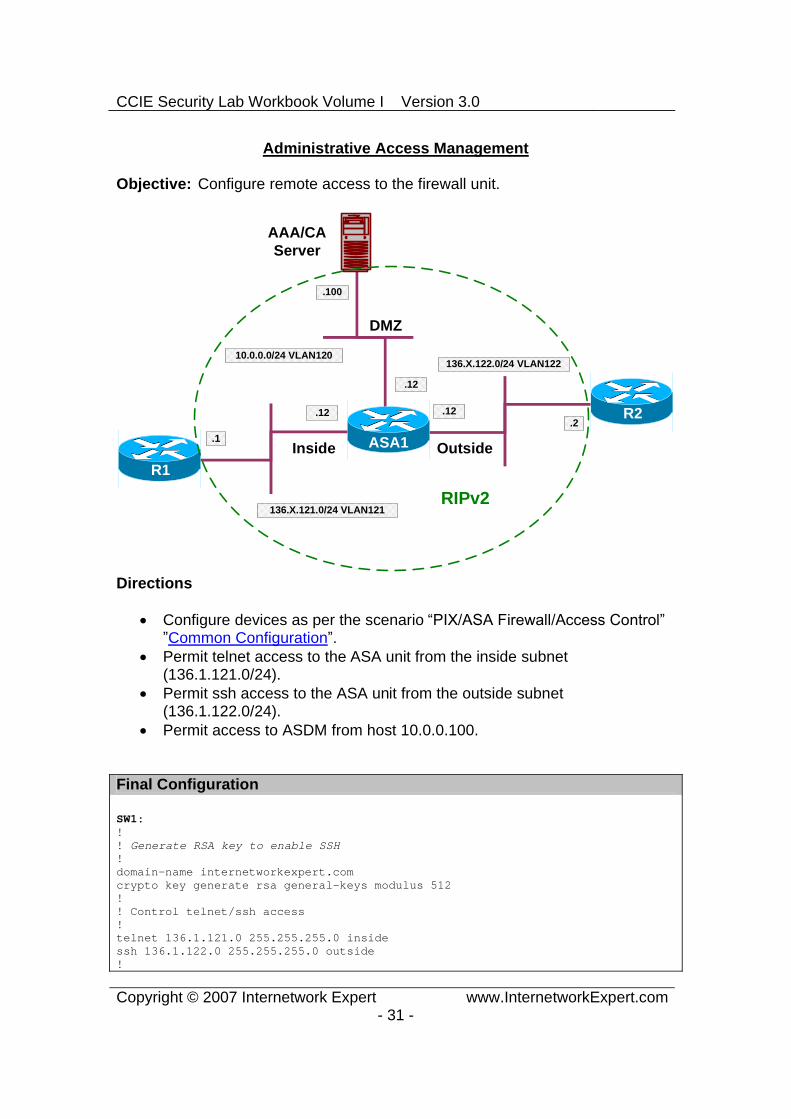
Objective: Configure remote access to the firewall unit.
ASA1
R1
R2
AAA/CAServer
Inside Outside
DMZ
136.X.122.0/24 VLAN122
R3.1
.2
.100
136.X.121.0/24 VLAN121
10.0.0.0/24 VLAN120
.12 .12
.12
RIPv2
Directions
Configure devices as per the scenario “PIX/ASA Firewall/Access Control” ”Common Configuration”.
Permit telnet access to the ASA unit from the inside subnet (136.1.121.0/24).
Permit ssh access to the ASA unit from the outside subnet (136.1.122.0/24).
Permit access to ASDM from host 10.0.0.100.
Final Configuration
SW1:!! Generate RSA key to enable SSH!domain-name internetworkexpert.com crypto key generate rsa general-keys modulus 512 !! Control telnet/ssh access !telnet 136.1.121.0 255.255.255.0 inside ssh 136.1.122.0 255.255.255.0 outside !

CCIE Security Lab Workbook Volume I Version 3.0
Copyright © 2007 Internetwork Expert www.InternetworkExpert.com- 32 -
! Define telnet/ssh password!passwd cisco !! Enable HTTP server and control HTTP access!http server enable http 10.0.0.100 255.255.255.255 dmz
Verification
AAA/CA Server:
Use your browser to connet to the ASA firewall. Enter enable password on authentication, if it’s set.
R1>telnet 136.1.121.12Trying 136.1.121.12 ... Open
User Access Verification
Password: ciscoType help or '?' for a list of available commands.

CCIE Security Lab Workbook Volume I Version 3.0
Copyright © 2007 Internetwork Expert www.InternetworkExpert.com- 33 -
ASA1>
R2#ssh -l pix 136.1.122.12
Password: ciscoType help or '?' for a list of available commands. ASA1> enPassword:ASA1# who 0: 136.1.121.1
ASA1# show ssh sess
SID Client IP Version Mode Encryption Hmac State Username 0 136.1.122.2 1.5 - 3DES - SessionStarted pix
Further Reading
Managing System Access

CCIE Security Lab Workbook Volume I Version 3.0
Copyright © 2007 Internetwork Expert www.InternetworkExpert.com- 34 -
ICMP Traffic Management
Objective: Limit ICMP traffic to/from the firewall unit.
ASA1
R1
R2
AAA/CAServer
Inside Outside
DMZ
136.X.122.0/24 VLAN122
R3.1
.2
.100
136.X.121.0/24 VLAN121
10.0.0.0/24 VLAN120
.12 .12
.12
RIPv2
Directions
Configure devices as per the scenario “PIX/ASA Firewall/Access Control” ”Common Configuration”.
Configure the firewall such that no one could ping it. However, make sure firewall itself is able to ping anyone.
To achieve this task, permit ICMP echo-reply messages to be accepted on any firewall interface.
Additionally, make sure that pMTU discovery and traceroute work successfully from the firewall.
To achieve this task, permit ICMP unreachables and time-exceeded messages to be accepted on any firewall interface.
All other ICMP messages terminating on firewall interfaces should be discarded.
Final Configuration
ASA1:icmp permit any echo-reply outside icmp permit any echo-reply inside icmp permit any echo-reply dmz !icmp permit any time-exceeded outside
CCIE Security Lab Workbook Volume I Version 3.0
Copyright © 2007 Internetwork Expert www.InternetworkExpert.com- 35 -
icmp permit any unreachable outside !icmp permit any time-exceeded inside icmp permit any unreachable inside !icmp permit any time-exceeded dmz icmp permit any unreachable dmz
Verification
ASA1# ping 136.1.122.2Type escape sequence to abort. Sending 5, 100-byte ICMP Echos to 136.1.122.2, timeout is 2 seconds: !!!!!Success rate is 100 percent (5/5), round-trip min/avg/max = 1/1/1 ms
ASA1# ping 136.1.121.1Type escape sequence to abort. Sending 5, 100-byte ICMP Echos to 136.1.121.1, timeout is 2 seconds: !!!!!Success rate is 100 percent (5/5), round-trip min/avg/max = 1/2/10 ms
ASA1# ping 10.0.0.100Type escape sequence to abort. Sending 5, 100-byte ICMP Echos to 10.0.0.100, timeout is 2 seconds: !!!!!Success rate is 100 percent (5/5), round-trip min/avg/max = 1/2/10 ms
ASA1# trace 10.0.0.100
Type escape sequence to abort. Tracing the route to 10.0.0.100
1 10.0.0.100 0 msec 0 msec 0 msec
ASA1# trace 136.1.122.2
Type escape sequence to abort. Tracing the route to 136.1.122.2
1 136.1.122.2 10 msec * 0 msec
ASA1# trace 136.1.121.1
Type escape sequence to abort. Tracing the route to 136.1.121.1
1 136.1.121.1 0 msec * 0 msec
R2#ping 136.1.121.12
Type escape sequence to abort. Sending 5, 100-byte ICMP Echos to 136.1.121.12, timeout is 2 seconds: .....Success rate is 0 percent (0/5)
R1#ping 136.1.121.12
Type escape sequence to abort. Sending 5, 100-byte ICMP Echos to 136.1.121.12, timeout is 2 seconds:

CCIE Security Lab Workbook Volume I Version 3.0
Copyright © 2007 Internetwork Expert www.InternetworkExpert.com- 36 -
.....Success rate is 0 percent (0/5)
Further Reading
Command Reference: ICMP

CCIE Security Lab Workbook Volume I Version 3.0
Copyright © 2007 Internetwork Expert www.InternetworkExpert.com- 37 -
Configuring Filtering Services
Objective: Configure the firewall for application-level filtering.
ASA1
R1
R2
AAA/CAServer
Inside Outside
DMZ
136.X.122.0/24 VLAN122
R3.1
.2
.100
136.X.121.0/24 VLAN121
10.0.0.0/24 VLAN120
.12 .12
.12
RIPv2
Directions
Configure devices as per the scenario “PIX/ASA Firewall/Access Control” ”Common Configuration”.
Filter ActiveX and JavaScript from all HTTP requests on port 80. Configure the ASA to use Websense URL filtering server at 10.0.0.100. Filter HTTP URL from 136.1.121.0/24 network on ports 80 and 8080.
Block proxy-requests going on port 8080. Additionally, configure FTP filtering on port 21 for network 136.1.121.0/24.
Deny interactive FTP connections. In case if URL server failure, HTTP/FTP requests should be allowed.
Final Configuration
SW1:url-server (dmz) host 10.0.0.100 !filter activex 80 0 0 0 0filter java 80 0 0 0 0filter ftp 21 136.1.121.0 255.255.255.0 0 0 allow interact-blockfilter url 8080 136.1.121.0 255.255.255.0 0 0 allow proxy-blockfilter url http 136.1.121.0 255.255.255.0 0 0 allow

CCIE Security Lab Workbook Volume I Version 3.0
Copyright © 2007 Internetwork Expert www.InternetworkExpert.com- 38 -
Verification
You can install a trial version of Websense filtering server. Use your Test PC to send a few HTTP requests from inside after that:
ASA1# show url-server statistics
Global Statistics: --------------------URLs total/allowed/denied 2/2/0 URLs allowed by cache/server 0/2 URLs denied by cache/server 0/0 HTTPSs total/allowed/denied 0/0/0 HTTPSs allowed by cache/server 0/0 HTTPSs denied by cache/server 0/0 FTPs total/allowed/denied 0/0/0 FTPs allowed by cache/server 0/0 FTPs denied by cache/server 0/0 Requests dropped 0 Server timeouts/retries 0/0 Processed rate average 60s/300s 0/0 requests/second Denied rate average 60s/300s 0/0 requests/second Dropped rate average 60s/300s 0/0 requests/second
Server Statistics: --------------------10.0.0.100 UP Vendor websense Port 15868 Requests total/allowed/denied 2/2/0 Server timeouts/retries 0/0 Responses received 2 Response time average 60s/300s 0/0
URL Packets Sent and Received Stats: ------------------------------------Message Sent Received STATUS_REQUEST 9601 9601 LOOKUP_REQUEST 2 2 LOG_REQUEST 0 NA
Errors:-------RFC noncompliant GET method 0 URL buffer update failure 0
ASA1# show running-config filter filter activex 80 0.0.0.0 0.0.0.0 0.0.0.0 0.0.0.0filter java 80 0.0.0.0 0.0.0.0 0.0.0.0 0.0.0.0filter ftp 21 136.1.121.0 255.255.255.0 0.0.0.0 0.0.0.0 allow interact-blockfilter url 8080 136.1.121.0 255.255.255.0 0.0.0.0 0.0.0.0 allow proxy-blockfilter url http 136.1.121.0 255.255.255.0 0.0.0.0 0.0.0.0 allow
Further Reading
Applying Filtering Services

CCIE Security Lab Workbook Volume I Version 3.0
Copyright © 2007 Internetwork Expert www.InternetworkExpert.com- 39 -
Configuring NAT
Dynamic NAT and PAT
Objective: Configure dynamic NAT translation rules.
Directions
Configure devices as per the scenario “PIX/ASA Firewall/Access Control” ”Common Configuration”.
Enable nat-control on the firewall. NAT-Control requires every connection to have a NAT entry created
before being permitted outbound (just like with PIX OS 6.x). Configure NAT such that hosts on the inside going to outside have
their addresses translated into address pool 136.1.122.100-110. Use interface IP address as PAT backup.
Configure NAT such that hosts on the DMZ going to outside havetheir addresses translated into address pool 136.1.122.200-210. Use the last IP address in the range as PAT backup.
Configure NAT such that hosts on the inside going into DMZ have their addresses translated into interface IP address via PAT.

CCIE Security Lab Workbook Volume I Version 3.0
Copyright © 2007 Internetwork Expert www.InternetworkExpert.com- 40 -
Final Configuration
ASA1:nat-control!! Configure global address pools !
!! Outside Pool for inside hosts!global (outside) 1 136.1.122.100-136.1.122.110 global (outside) 1 interface
!! DMZ pool for inside hosts!global (dmz) 1 interface
!! Outside pool for DMZ hosts!global (outside) 2 136.1.122.200-136.1.122.209 global (outside) 2 136.1.122.210
!! NAT rules!nat (inside) 1 136.1.121.0 255.255.255.0 nat (dmz) 2 10.0.0.0 255.255.255.0
Verification
ASA1(config)# show nat
NAT policies on Interface inside: match ip inside 136.1.121.0 255.255.255.0 outside any dynamic translation to pool 1 (136.1.122.100 - 136.1.122.110) translate_hits = 0, untranslate_hits = 0 match ip inside 136.1.121.0 255.255.255.0 inside any dynamic translation to pool 1 (No matching global) translate_hits = 0, untranslate_hits = 0 match ip inside 136.1.121.0 255.255.255.0 dmz any dynamic translation to pool 1 (10.0.0.12 [Interface PAT]) translate_hits = 0, untranslate_hits = 0 match ip inside any outside any no translation group, implicit deny policy_hits = 0 match ip inside any dmz any no translation group, implicit deny policy_hits = 0
NAT policies on Interface dmz: match ip dmz 10.0.0.0 255.255.255.0 outside any dynamic translation to pool 2 (136.1.122.200 - 136.1.122.209) translate_hits = 0, untranslate_hits = 0 match ip dmz 10.0.0.0 255.255.255.0 dmz any dynamic translation to pool 2 (No matching global)

CCIE Security Lab Workbook Volume I Version 3.0
Copyright © 2007 Internetwork Expert www.InternetworkExpert.com- 41 -
translate_hits = 0, untranslate_hits = 0 match ip dmz any outside any no translation group, implicit deny policy_hits = 0
ASA1(config)# show run global global (outside) 1 136.1.122.100-136.1.122.110 global (outside) 2 136.1.122.200-136.1.122.209 global (outside) 1 interface global (outside) 2 136.1.122.210 global (dmz) 1 interface
R1#telnet 136.1.122.2Trying 136.1.122.2 ... Open
User Access Verification
Password:R2>Rack1AS>12[Resuming connection 12 to asa1 ... ]
ASA1(config)# show xlate1 in use, 1 most used Global 136.1.122.100 Local 136.1.121.1
R1#telnet 10.0.0.100 80Trying 10.0.0.100, 80 ... Open
ASA1(config)# show x2 in use, 2 most used PAT Global 10.0.0.12(1024) Local 136.1.121.1(11006)Global 136.1.122.100 Local 136.1.121.1
AAA/CA Server:

CCIE Security Lab Workbook Volume I Version 3.0
Copyright © 2007 Internetwork Expert www.InternetworkExpert.com- 42 -
ASA1(config)# show x3 in use, 3 most used Global 136.1.122.200 Local 10.0.0.100 PAT Global 10.0.0.12(1024) Local 136.1.121.1(11006)Global 136.1.122.100 Local 136.1.121.1
Further Reading
Applying NAT

CCIE Security Lab Workbook Volume I Version 3.0
Copyright © 2007 Internetwork Expert www.InternetworkExpert.com- 43 -
Static NAT and PAT
Objective: Configure static IP and port mappings on the PIX/ASA firewall.
ASA1
R1
R2
AAA/CAServer
Inside Outside
DMZ
136.X.122.0/24 VLAN122
R3.1
.2
.100
136.X.121.0/24 VLAN121
10.0.0.0/24 VLAN120
.12 .12
.12
RIPv2
Directions
Configure devices as per the scenario “PIX/ASA Firewall/Access Control” ”Common Configuration”.
Enable nat-control on the firewall. Make RIP passive on the outside interface of the ASA. Map DMZ ip address 10.0.0.100 to outside 136.1.122.100. Configure Static PAT such that telnet session to the outside interface are
redirected to R1. Configure Static PAT such that DNS requests sent to the ASA inside
interface are redirected to R2. Make sure inside hosts are translated when they go outside.
Configure access-list required to satisfy the mentioned connectivity requirements.
Final Configuration
ASA1:nat-control!! Prevent R2 from learning inside/DMZ IP addresses!router rip
CCIE Security Lab Workbook Volume I Version 3.0
Copyright © 2007 Internetwork Expert www.InternetworkExpert.com- 44 -
passive-interface outside !! DMZ host !static (dmz,outside) 136.1.122.100 10.0.0.100 !! Telnet redirection!static (inside,outside) tcp interface 23 136.1.121.1 23 !! DNS redirection!static (outside,inside) udp interface 53 136.1.122.2 53 !! Translate inside->outside for DNS requests !nat (inside) 1 0 0 global (outside) 1 interface !! Access-list/Group to permit inbound connections!access-list OUTSIDE_IN extended permit ip any host 136.1.122.100access-list OUTSIDE_IN extended permit tcp any host 136.1.122.12 eq telnet !access-group OUTSIDE_IN in interface outside
Verification
R2#telnet 136.1.122.100 80Trying 136.1.122.100, 80 ... Open
R2#disc 1 Closing connection to 136.1.122.100 [confirm]
R2#telnet 136.1.122.12 Trying 136.1.122.12 ... Open
Password required, but none set
[Connection to 136.1.122.12 closed by foreign host]
R2#conf tEnter configuration commands, one per line. End with CNTL/Z. R2(config)#ip dns server R2(config)#ip host TEST 136.1.122.2
R1#conf tEnter configuration commands, one per line. End with CNTL/Z. R1(config)#ip name-server 136.1.121.12R1(config)#ip domain-lookupR1#ping TESTTranslating "TEST"...domain server (136.1.121.12) [OK]
Type escape sequence to abort. Sending 5, 100-byte ICMP Echos to 136.1.122.2, timeout is 2 seconds: .....Success rate is 0 percent (0/5)

CCIE Security Lab Workbook Volume I Version 3.0
Copyright © 2007 Internetwork Expert www.InternetworkExpert.com- 45 -
Further Reading
Applying NAT

CCIE Security Lab Workbook Volume I Version 3.0
Copyright © 2007 Internetwork Expert www.InternetworkExpert.com- 46 -
Dynamic Policy NAT
Objective: Select outbound NAT pool based on policy.
ASA1
R1
R2
AAA/CAServer
Inside Outside
DMZ
136.X.122.0/24 VLAN122
R3.1
.2
.100
136.X.121.0/24 VLAN121
10.0.0.0/24 VLAN120
.12 .12
.12
RIPv2
Directions
Configure devices as per the scenario “PIX/ASA Firewall/Access Control” ”Common Configuration”.
Enable nat-control on the firewall. Make RIP passive on the ASA outside interface. Telnet connections going outside should be PAT translated using the IP
address 136.1.122.100 ICMP packets going outside should be PAT translated using the IP
address 136.1.122.101 Use access-lists TELNET and ICMP to distinguish two types of traffic. Configure two NAT pools and set up policy NAT to reflect the
requirements. Everything else should be PAT translated using the outside interface IP.
Final Configuration
ASA1:nat-control!! Prevent R2 from learning inside/DMZ IP addresses!router rip

CCIE Security Lab Workbook Volume I Version 3.0
Copyright © 2007 Internetwork Expert www.InternetworkExpert.com- 47 -
passive-interface outside !access-list ICMP extended permit icmp any any access-list TELNET extended permit tcp any any eq telnet !nat (inside) 1 access-list ICMP nat (inside) 2 access-list TELNET nat (inside) 3 0 0 !global (outside) 1 136.1.122.100 global (outside) 2 136.1.122.101 global (outside) 3 interface !! Permit the returning ping responses!access-list OUTSIDE_IN extended permit icmp any any access-group OUTSIDE_IN in interface outside
Verification
R1#telnet 136.1.122.2Trying 136.1.122.2 ... Open
User Access Verification
Password:R2>
ASA1(config)# show xlate1 in use, 10 most used PAT Global 136.1.122.101(1024) Local 136.1.121.1(11007)
R1#ping 136.1.122.2
Type escape sequence to abort. Sending 5, 100-byte ICMP Echos to 136.1.122.2, timeout is 2 seconds: !!!!!Success rate is 100 percent (5/5), round-trip min/avg/max = 4/4/4 ms
R1#
ASA1# show x5 in use, 10 most used PAT Global 136.1.122.100(10) Local 136.1.121.1 ICMP id 1842PAT Global 136.1.122.100(9) Local 136.1.121.1 ICMP id 1841PAT Global 136.1.122.100(8) Local 136.1.121.1 ICMP id 1840PAT Global 136.1.122.100(7) Local 136.1.121.1 ICMP id 1839PAT Global 136.1.122.100(6) Local 136.1.121.1 ICMP id 1838
Further Reading
Policy NAT

CCIE Security Lab Workbook Volume I Version 3.0
Copyright © 2007 Internetwork Expert www.InternetworkExpert.com- 48 -
Static Policy NAT and PAT
Objective: Implement policy decision within static PAT configuration.
ASA1
R1
R2
AAA/CAServer
Inside Outside
DMZ
136.X.122.0/24 VLAN122
R3.1
.2
.100
136.X.121.0/24 VLAN121
10.0.0.0/24 VLAN120
.12 .12
.12
RIPv2
Directions
Configure devices as per the scenario “PIX/ASA Firewall/Access Control” ”Common Configuration”.
Enable nat-control on the firewall. Make RIP passive on the ASA outside interface. Create Loopback0 interface on R2 with ip address 150.X.2.2/24 and
advertise it into RIP. Redirect telnet connections going from 136.X.122.0/24 to the firewall
outside interface to R1. Redirect HTTP connections going from 150.X.2.0/24 to the firewall outside
interface to AAA/CA server. Create and apply the necessary access-group to the outside interface.
Final Configuration
R2:interface Loopback0 ip address 150.1.2.2 255.255.255.0 !router rip version 2 no auto-summary network 150.1.0.0
CCIE Security Lab Workbook Volume I Version 3.0
Copyright © 2007 Internetwork Expert www.InternetworkExpert.com- 49 -
ASA1:nat-control!! Prevent R2 from learning inside/DMZ IP addresses!router rip passive-interface outside
!! Access-list to match Telnet traffic from VLAN122!access-list VLAN122 ext per tcp h 136.1.121.1 eq 23 136.1.122.0 255.255.255.0
!! Accesslist to match HTTP traffic from R2’s Lo0!access-list LO0 ext permit tcp h 10.0.0.100 eq 80 150.1.2.0 255.255.255.0
!! Static Policy PAT for VLAN122 Telnet!static (i,o) tcp interface 23 access-list VLAN122 !! Static Policy PAT for LO0 HTTP!static (dmz,o) tcp interface 80 access-list LO0!! Outside ACL !access-list OUTSIDE_IN permit tcp any host 136.1.122.12 eq 80 access-list OUTSIDE_IN permit tcp any host 136.1.122.12 eq 23 !access-group OUTSIDE_IN in interface outside
Verification
R2#telnet 136.1.122.12 Trying 136.1.122.12 ... Open
Password required, but none set
[Connection to 136.1.122.12 closed by foreign host]
R2#telnet 136.1.122.12 80 /source-interface loopback 0 Trying 136.1.122.12, 80 ... Open
HTTP/1.1 400 Bad Request Server: Microsoft-IIS/5.0 Date: Mon, 08 Jan 2007 12:10:00 GMT Content-Type: text/html Content-Length: 87
<html><head><title>Error</title></head><body>The parameter is incorrect. </body></html>[Connection to 136.1.122.12 closed by foreign host]
ASA1(config)# show xlate debug

CCIE Security Lab Workbook Volume I Version 3.0
Copyright © 2007 Internetwork Expert www.InternetworkExpert.com- 50 -
2 in use, 10 most used Flags: D - DNS, d - dump, I - identity, i - dynamic, n - no random, r - portmap, s - static TCP PAT from inside:136.1.121.1/23 to outside(VLAN122):136.1.122.12/23 flags sr idle 0:00:24 timeout 0:00:00 TCP PAT from dmz:10.0.0.100/80 to outside(LO0):136.1.122.12/80 flags sr idle 0:00:17 timeout 0:00:00
Further Reading
Policy NAT

CCIE Security Lab Workbook Volume I Version 3.0
Copyright © 2007 Internetwork Expert www.InternetworkExpert.com- 51 -
Identity NAT and NAT Exemption
Objective: Configure NAT preserving IP address or disable NAT translations based on policy.
ASA1
R1
R2
AAA/CAServer
Inside Outside
DMZ
136.X.122.0/24 VLAN122
R3.1
.2
.100
136.X.121.0/24 VLAN121
10.0.0.0/24 VLAN120
.12 .12
.12
RIPv2
Directions
Configure devices as per the scenario “PIX/ASA Firewall/Access Control” ”Common Configuration”.
Enable nat-control on the firewall. Configure the firewall such that the network 136.X.121.0/24 is translated
to itself. Configure the firewall such that no NAT is performed for the AAA/CA
server 10.0.0.100.
Final Configuration
ASA1:nat-control!! Identity NAT!nat (inside) 0 136.1.121.0 255.255.255.0
!! Access-List to match traffic from AAA/CA server!access-list SERVER extended permit ip host 10.0.0.100 any

CCIE Security Lab Workbook Volume I Version 3.0
Copyright © 2007 Internetwork Expert www.InternetworkExpert.com- 52 -
!! NAT Exemption!nat (dmz) 0 access-list SERVER
!! Access-List to perform some basic testing!access-list OUTSIDE_IN ext permit ip any any access-group OUTSIDE_IN in interface outside
Verification
R2#ping 10.0.0.100
Type escape sequence to abort. Sending 5, 100-byte ICMP Echos to 10.0.0.100, timeout is 2 seconds: !!!!!Success rate is 100 percent (5/5), round-trip min/avg/max = 1/2/4 ms
R2#ping 136.1.121.1
Type escape sequence to abort. Sending 5, 100-byte ICMP Echos to 136.1.121.1, timeout is 2 seconds: .....Success rate is 0 percent (0/5)
R1#ping 136.1.122.2
Type escape sequence to abort. Sending 5, 100-byte ICMP Echos to 136.1.122.2, timeout is 2 seconds: !!!!!Success rate is 100 percent (5/5), round-trip min/avg/max = 4/4/4 ms R1#
R2#ping 136.1.121.1
Type escape sequence to abort. Sending 5, 100-byte ICMP Echos to 136.1.121.1, timeout is 2 seconds: !!!!!Success rate is 100 percent (5/5), round-trip min/avg/max = 1/3/4 ms R2#
ASA1(config)# show x1 in use, 10 most used Global 136.1.121.1 Local 136.1.121.1
Further Reading
Bypassing NAT

CCIE Security Lab Workbook Volume I Version 3.0
Copyright © 2007 Internetwork Expert www.InternetworkExpert.com- 53 -
Outside Dynamic NAT
Objective: Configure address translation for hosts from lower security level interface.
ASA1
R1
R2
AAA/CAServer
Inside Outside
DMZ
136.X.122.0/24 VLAN122
R3.1
.2
.100
136.X.121.0/24 VLAN121
10.0.0.0/24 VLAN120
.12 .12
.12
RIPv2
Directions
Configure devices as per the scenario “PIX/ASA Firewall/Access Control” ”Common Configuration”.
Enable nat-control on the firewall. Make RIP passive on the inside interface. Configure outside NAT rule to translate network 136.X.122.0/24 on
outside interface. As soon as you configure dynamic outside NAT, you need to configure
static NAT entry for every server on the low-security interface you wish to access from high-security interface.
Also, any outside host, access the inside should have a NAT entry created in order to create inbound connection.
Configure NAT pool on inside interface to use inside interface IP address. Configure static NAT mapping for AAA/CA server on the inside interface.
Use IP address 136.X.121.100. Configure dynamic NAT necessary to access the AAA/CA server.

CCIE Security Lab Workbook Volume I Version 3.0
Copyright © 2007 Internetwork Expert www.InternetworkExpert.com- 54 -
Final Configuration
ASA1:nat-control!router rip passive-interface inside
!! Outside NAT config!nat (outside) 1 136.1.122.0 255.255.255.0 outside global (inside) 1 interface
!! Fixup for DMZ server!static (dmz,inside) 136.1.121.100 10.0.0.100
!! Dynamic NAT to access DMZ from inside.! Required to reach the static mapping for AAA/CA server.!nat (inside) 1 0 0 global (dmz) 1 interface
!! Access-List to perform some basic testing from outside!access-list OUTSIDE_IN ext permit ip any any access-group OUTSIDE_IN in interface outside
Verification
R2#ping 136.1.121.1
Type escape sequence to abort. Sending 5, 100-byte ICMP Echos to 136.1.121.1, timeout is 2 seconds: !!!!!Success rate is 100 percent (5/5), round-trip min/avg/max = 1/2/4 ms R2#
ASA1(config)# show x7 in use, 10 most used Global 136.1.121.100 Local 10.0.0.100 PAT Global 136.1.121.12(5) Local 136.1.122.2 ICMP id 3200PAT Global 136.1.121.12(4) Local 136.1.122.2 ICMP id 3199PAT Global 136.1.121.12(3) Local 136.1.122.2 ICMP id 3198PAT Global 136.1.121.12(2) Local 136.1.122.2 ICMP id 3197PAT Global 136.1.121.12(1) Local 136.1.122.2 ICMP id 3196
R1#ping 136.1.121.100
Type escape sequence to abort. Sending 5, 100-byte ICMP Echos to 136.1.121.100, timeout is 2 seconds: .....Success rate is 0 percent (0/5)

CCIE Security Lab Workbook Volume I Version 3.0
Copyright © 2007 Internetwork Expert www.InternetworkExpert.com- 55 -
R1#telnet 136.1.121.100 80Trying 136.1.121.100, 80 ... Open
HTTP/1.1 400 Bad Request Server: Microsoft-IIS/5.0 Date: Mon, 08 Jan 2007 14:06:26 GMT Content-Type: text/html Content-Length: 87
<html><head><title>Error</title></head><body>The parameter is incorrect. </body></html>[Connection to 136.1.121.100 closed by foreign host]
Further Reading
Using Dynamic NAT and PAT
CCIE Security Lab Workbook Volume I Version 3.0
Copyright © 2007 Internetwork Expert www.InternetworkExpert.com- 56 -
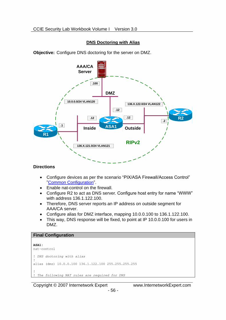
DNS Doctoring with Alias
Objective: Configure DNS doctoring for the server on DMZ.
ASA1
R1
R2
AAA/CAServer
Inside Outside
DMZ
136.X.122.0/24 VLAN122
R3.1
.2
.100
136.X.121.0/24 VLAN121
10.0.0.0/24 VLAN120
.12 .12
.12
RIPv2
Directions
Configure devices as per the scenario “PIX/ASA Firewall/Access Control” ”Common Configuration”.
Enable nat-control on the firewall. Configure R2 to act as DNS server. Configure host entry for name “WWW”
with address 136.1.122.100. Therefore, DNS server reports an IP address on outside segment for
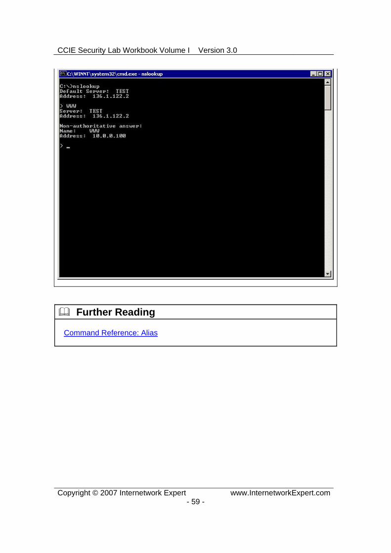
AAA/CA server. Configure alias for DMZ interface, mapping 10.0.0.100 to 136.1.122.100. This way, DNS response will be fixed, to point at IP 10.0.0.100 for users in
DMZ.
Final Configuration
ASA1:nat-control
! DNS doctoring with alias !alias (dmz) 10.0.0.100 136.1.122.100 255.255.255.255
!! The following NAT rules are required for DNS

CCIE Security Lab Workbook Volume I Version 3.0
Copyright © 2007 Internetwork Expert www.InternetworkExpert.com- 57 -
! request to flow to R2!nat (dmz) 1 0 0 global (outside) 1 interface
R2:ip dns server ip host WWW 136.1.122.100
Verification
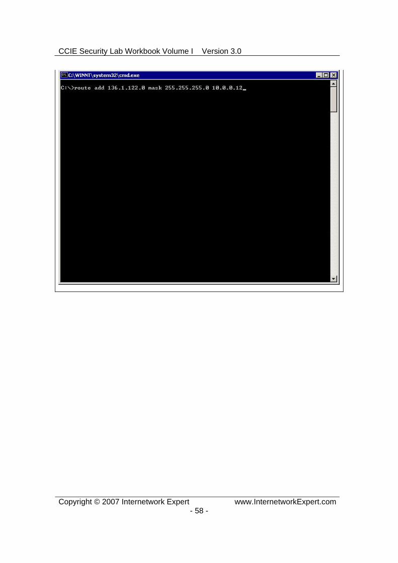
Configure Test PC in VLAN120:
CCIE Security Lab Workbook Volume I Version 3.0
Copyright © 2007 Internetwork Expert www.InternetworkExpert.com- 58 -
CCIE Security Lab Workbook Volume I Version 3.0
Copyright © 2007 Internetwork Expert www.InternetworkExpert.com- 59 -
Further Reading
Command Reference: Alias
CCIE Security Lab Workbook Volume I Version 3.0
Copyright © 2007 Internetwork Expert www.InternetworkExpert.com- 60 -
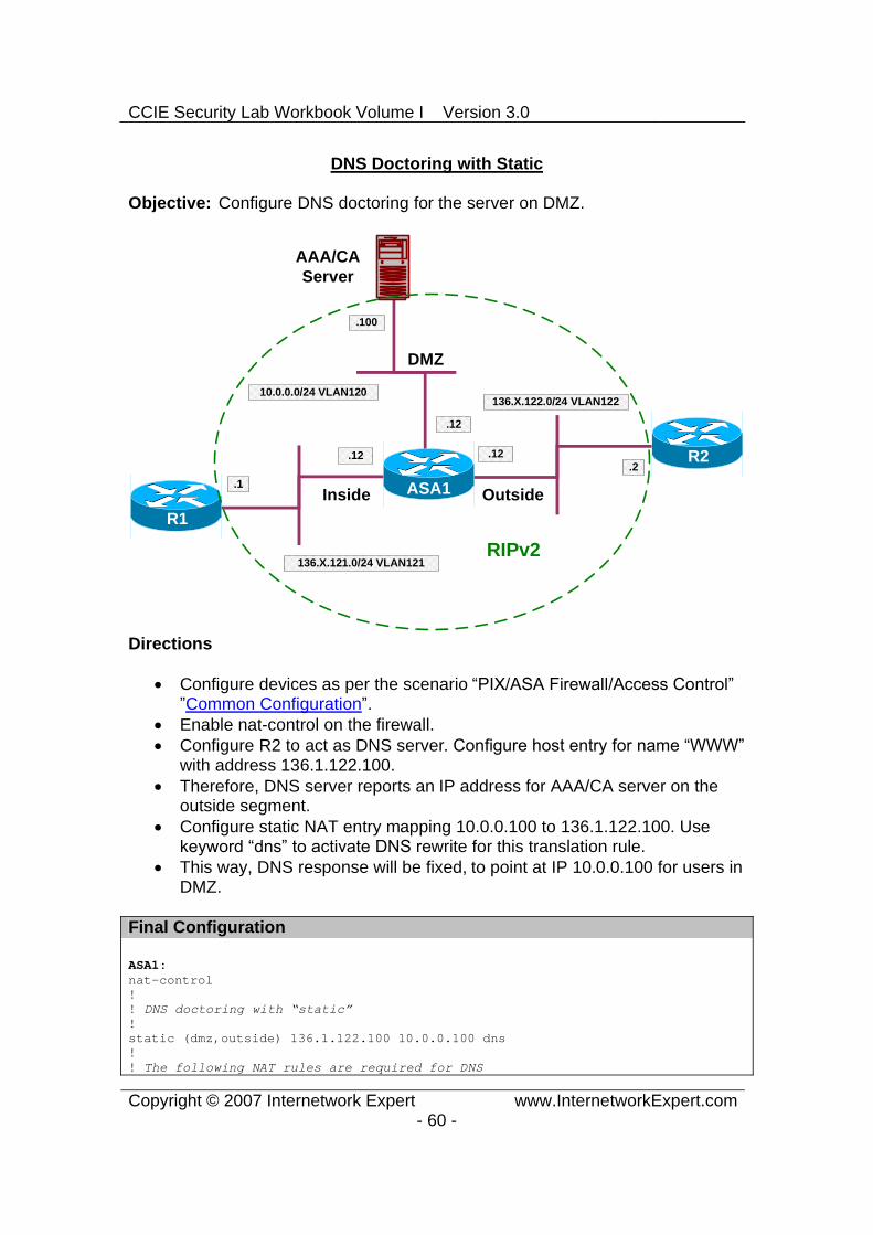
DNS Doctoring with Static
Objective: Configure DNS doctoring for the server on DMZ.
ASA1
R1
R2
AAA/CAServer
Inside Outside
DMZ
136.X.122.0/24 VLAN122
R3.1
.2
.100
136.X.121.0/24 VLAN121
10.0.0.0/24 VLAN120
.12 .12
.12
RIPv2
Directions
Configure devices as per the scenario “PIX/ASA Firewall/Access Control” ”Common Configuration”.
Enable nat-control on the firewall. Configure R2 to act as DNS server. Configure host entry for name “WWW”
with address 136.1.122.100. Therefore, DNS server reports an IP address for AAA/CA server on the
outside segment. Configure static NAT entry mapping 10.0.0.100 to 136.1.122.100. Use keyword “dns” to activate DNS rewrite for this translation rule.
This way, DNS response will be fixed, to point at IP 10.0.0.100 for users in DMZ.
Final Configuration
ASA1:nat-control!! DNS doctoring with “static”!static (dmz,outside) 136.1.122.100 10.0.0.100 dns !! The following NAT rules are required for DNS

CCIE Security Lab Workbook Volume I Version 3.0
Copyright © 2007 Internetwork Expert www.InternetworkExpert.com- 61 -
! request to flow to R2!nat (dmz) 1 0 0 global (outside) 1 interface
R2:ip dns server ip host WWW 136.1.122.100
Verification
Configure Test PC in VLAN120:

CCIE Security Lab Workbook Volume I Version 3.0
Copyright © 2007 Internetwork Expert www.InternetworkExpert.com- 62 -

CCIE Security Lab Workbook Volume I Version 3.0
Copyright © 2007 Internetwork Expert www.InternetworkExpert.com- 63 -
Further Reading
DNS and NAT

CCIE Security Lab Workbook Volume I Version 3.0
Copyright © 2007 Internetwork Expert www.InternetworkExpert.com- 64 -
Same-Security Traffic and NAT
Objective: Configure same-security level interface on the firewall.
136.X.123.0/24 VLAN123
.12
ASA1
R1
R2
E0/1 E0/2
136.X.122.0/24 VLAN122
R3.1
.2
136.X.121.0/24 VLAN121
.12 .12
E0/0
R3.3
E0/0
E0/0
E0/0
Directions
The goal is to observe how NAT works with same-security level interfaces. By default, you do not need to do NAT between same-security level
interfaces, even if nat-control is enabled. However, you do need to configure NAT rules if you define dynamic NAT
for either of the same-security level interfaces. Pre-configure as follows:
o Create necessary VLANs on SW1 an SW2. o Configure the respective switchports to reflect the diagram
topology.o Configure trunking as necessary between SW1 and SW2. o Configure the ASA interfaces E 0/1 and E 0/2 to be nameifs:
“inside1” and “inside2” with security-level 100. Configure E0/0 as “outside” with default security level.
o Configure IP addressing on all devices as per the diagram. o Configure default routes on R1 and R2 to point at the firewall.
Configure default route on the firewall to point at R3. o Configure static routes for 136.X.122.0/24 and 136.X.121.0/24 on
R3 to point at the firewall.
Enable NAT control on the firewall and enalbe the same-security traffic to pass between interfaces.
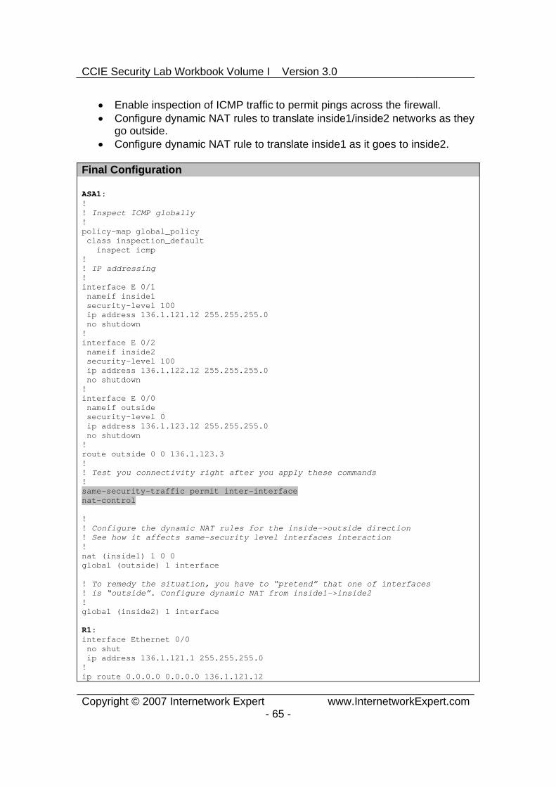
CCIE Security Lab Workbook Volume I Version 3.0
Copyright © 2007 Internetwork Expert www.InternetworkExpert.com- 65 -
Enable inspection of ICMP traffic to permit pings across the firewall. Configure dynamic NAT rules to translate inside1/inside2 networks as they
go outside. Configure dynamic NAT rule to translate inside1 as it goes to inside2.
Final Configuration
ASA1:!! Inspect ICMP globally!policy-map global_policy class inspection_default inspect icmp !! IP addressing!interface E 0/1 nameif inside1 security-level 100 ip address 136.1.121.12 255.255.255.0 no shutdown !interface E 0/2 nameif inside2 security-level 100 ip address 136.1.122.12 255.255.255.0 no shutdown !interface E 0/0 nameif outside security-level 0 ip address 136.1.123.12 255.255.255.0 no shutdown !route outside 0 0 136.1.123.3 !! Test you connectivity right after you apply these commands!same-security-traffic permit inter-interface nat-control
!! Configure the dynamic NAT rules for the inside->outside direction! See how it affects same-security level interfaces interaction !nat (inside1) 1 0 0 global (outside) 1 interface
! To remedy the situation, you have to “pretend” that one of interfaces! is “outside”. Configure dynamic NAT from inside1->inside2 !global (inside2) 1 interface
R1:interface Ethernet 0/0 no shut ip address 136.1.121.1 255.255.255.0 !ip route 0.0.0.0 0.0.0.0 136.1.121.12

CCIE Security Lab Workbook Volume I Version 3.0
Copyright © 2007 Internetwork Expert www.InternetworkExpert.com- 66 -
R2:interface Ethernet 0/0 no shut ip address 136.1.122.2 255.255.255.0 !ip route 0.0.0.0 0.0.0.0 136.1.122.12
R3:interface Ethernet 0/0 no shut ip address 136.1.123.3 255.255.255.0 !ip route 136.1.122.0 255.255.255.0 136.1.123.12 ip route 136.1.121.0 255.255.255.0 136.1.123.12
SW1 & SW2: !! create VLANs and configure trunk links!vlan 121,122,123 !interface range Fa 0/21 - 23 switchport trunk encapsulation dot1q switchport mode trunk no shut
SW1:!! Configure switchports!interface Fa 0/1 switchport host switchport access vlan 121 !interface Fa 0/2 switchport host switchport access vlan 122 !interface Fa 0/3 switchport host switchport access vlan 123 !interface Fa 0/13 switchport host switchport access vlan 121
SW2:!! Configure switchports!interface Fa 0/12 switchport host switchport access vlan 123 !interface Fa 0/13 switchport host switchport access vlan 122

CCIE Security Lab Workbook Volume I Version 3.0
Copyright © 2007 Internetwork Expert www.InternetworkExpert.com- 67 -
Verification
1st case: “no natcontrol” & “no samesecurity permit interinterface”
R1#ping 136.1.123.3
Type escape sequence to abort. Sending 5, 100-byte ICMP Echos to 136.1.123.3, timeout is 2 seconds: !!!!!Success rate is 100 percent (5/5), round-trip min/avg/max = 100/174/196 ms
R1#ping 136.1.122.2
Type escape sequence to abort. Sending 5, 100-byte ICMP Echos to 136.1.122.2, timeout is 2 seconds: .....Success rate is 0 percent (0/5)
2nd case: “no natcontrol” & “samesecurity permit interinterface”
R1#ping 136.1.123.3
Type escape sequence to abort. Sending 5, 100-byte ICMP Echos to 136.1.123.3, timeout is 2 seconds: !!!!!Success rate is 100 percent (5/5), round-trip min/avg/max = 100/174/196 ms
R1#ping 136.1.122.2
Type escape sequence to abort. Sending 5, 100-byte ICMP Echos to 136.1.122.2, timeout is 2 seconds: !!!!!Success rate is 100 percent (5/5), round-trip min/avg/max = 105/177/197 ms
3rd case: “natcontrol” & “samesecurity permit interinterface”
R1#ping 136.1.123.3
Type escape sequence to abort. Sending 5, 100-byte ICMP Echos to 136.1.123.3, timeout is 2 seconds: .....Success rate is 0 percent (0/5)
%ASA-3-305005: No translation group found for icmp src inside1:136.1.121.1 dst outside:136.1.123.3 (type 8, code 0)
R1#ping 136.1.122.2
Type escape sequence to abort. Sending 5, 100-byte ICMP Echos to 136.1.122.2, timeout is 2 seconds: !!!!!Success rate is 100 percent (5/5), round-trip min/avg/max = 100/178/200 ms
4th case: “natcontrol” & “samesecurity permit interint” ﴾NAT inside>outside﴿
ASA1(config)# show running-config natnat (inside1) 1 0.0.0.0 0.0.0.0
ASA1(config)# show run globglobal (outside) 1 interface

CCIE Security Lab Workbook Volume I Version 3.0
Copyright © 2007 Internetwork Expert www.InternetworkExpert.com- 68 -
R1#ping 136.1.123.3
Type escape sequence to abort. Sending 5, 100-byte ICMP Echos to 136.1.123.3, timeout is 2 seconds: !!!!!Success rate is 100 percent (5/5), round-trip min/avg/max = 100/165/184 ms
R1#ping 136.1.122.2
Type escape sequence to abort. Sending 5, 100-byte ICMP Echos to 136.1.122.2, timeout is 2 seconds: .....Success rate is 0 percent (0/5)
%ASA-3-305006: portmap translation creation failed for icmp src inside1:136.1.121.1 dst inside2:136.1.122.2 (type 8, code 0)
ASA1(config)# show x5 in use, 5 most used PAT Global 136.1.123.12(5) Local 136.1.121.1 ICMP id 5733PAT Global 136.1.123.12(4) Local 136.1.121.1 ICMP id 5732PAT Global 136.1.123.12(3) Local 136.1.121.1 ICMP id 5731PAT Global 136.1.123.12(2) Local 136.1.121.1 ICMP id 5730PAT Global 136.1.123.12(1) Local 136.1.121.1 ICMP id 5729
5th case: “natcontrol” & “samesecurity permit interint” ﴾NAT inside>outside﴿(NAT inside1->inside2):
R1#ping 136.1.123.3
Type escape sequence to abort. Sending 5, 100-byte ICMP Echos to 136.1.123.3, timeout is 2 seconds: !!!!!Success rate is 100 percent (5/5), round-trip min/avg/max = 100/169/188 ms
R1#ping 136.1.122.2
Type escape sequence to abort. Sending 5, 100-byte ICMP Echos to 136.1.122.2, timeout is 2 seconds: !!!!!Success rate is 100 percent (5/5), round-trip min/avg/max = 100/169/192 ms
ASA1(config)# show x10 in use, 10 most used PAT Global 136.1.122.12(25) Local 136.1.121.1 ICMP id 1475PAT Global 136.1.122.12(24) Local 136.1.121.1 ICMP id 1474PAT Global 136.1.122.12(23) Local 136.1.121.1 ICMP id 1473PAT Global 136.1.122.12(22) Local 136.1.121.1 ICMP id 1472PAT Global 136.1.122.12(21) Local 136.1.121.1 ICMP id 1471PAT Global 136.1.123.12(15) Local 136.1.121.1 ICMP id 4417PAT Global 136.1.123.12(14) Local 136.1.121.1 ICMP id 4416PAT Global 136.1.123.12(13) Local 136.1.121.1 ICMP id 4415
Further Reading
Configuring Interface Parameters NAT and Same Security Level Interfaces

CCIE Security Lab Workbook Volume I Version 3.0
Copyright © 2007 Internetwork Expert www.InternetworkExpert.com- 69 -
Advanced Firewall
Firewall Contexts Configuration
Objective: Create firewall contexts and allocate interfaces.
R4
DMZ136.1.124.0/24 VLAN124
A: .121B: .122
.4
ASA1
R1 R2
R3
InsideB InsideA
Outside
136.1.0.0/24 VLAN122136.1.0.0/24 VLAN121
136.1.123.0/24 VLAN123
.12 .12
.3
.1 .2
R3
A: .121B: .122
Lo0: 150.1.4.4/24
Directions
The goal of this task is to create two virtual contexts, and configure shared interfaces. The NAT mappings will be used as tie-breakers for context selection.
Pre-configuration:
o Create VLANs 121,122,123,124. Assign the respective switchports to these VLANs.
o Configure the switchport corresponding to the ASA1 inside interface as 802.1q trunk.
o Configure IP addressing on the routers as per the diagram.o Configure static default routes at R1 and R2 to point at ASA1.
Configure the ASA as follows: Enable multiple-context mode and reboot into system context.

CCIE Security Lab Workbook Volume I Version 3.0
Copyright © 2007 Internetwork Expert www.InternetworkExpert.com- 70 -
Residing in system context:
o Configure hardware interfaces as follows:
Enable Ethernet 0/0, Ethernet 0/1, Ethernet 0/2. Configure two subinterfaces namely Ethernet0/1.121 and
Ethernet0/1.122 for VLANs 121 and 122 respectively on interface Ethernet 0/1.
o Make sure you have context “admin” created, with configurl “disk0:/admin.cfg”. Enable it as admin-context. The admin context should be initialized before anything else could be configured.
o Create context named “CustomerA” as follows:
Use configurl “disk0:/CustomerA.cfg” Allocate interfaces Ethernet0/1.121, Ethernet0/0 and
Ethernet0/2 to it. Map this interfaces to names “insideA”, “outside”, “dmz” respectively.
o Create context named “CustomerB” as follows:
Use configurl “disk0:/CustomerA.cfg” Allocate interfaces Ethernet0/1.122, Ethernet0/0 and
Ethernet0/2 to it. Map this interfaces to names “insideB”, “outside”, “dmz” respectively.
Change to context “CustomerA” and configure as follows:
o Use configurl “disk0:/CustomerA.cfg” o Configure IP addressing as per the diagram, use security levels
100, 50, 0 for the “inside”, “dmz” and “outside” interfaces respectively. Configure “nameifs” respectively.
o Configure static default route to R3. o Configute static route for 150.1.4.0/24 to R4. o Configure static PAT to translate 136.X.123.100 port 80 to
136.X.0.1 (R1) port 80. o Configure dynamic PAT for all inside users on “dmz” interface using
interface IP address. o Configure dynamic PAT for all inside users on “outside” interface
using interface IP address. o Create access-list OUTSIDE_IN as follows:
Permit TCP to 136.X.123.100 port 80. Permit ICMP echo-reply packets.
o Apply access-group OUTSIDE_IN to interface outside.

CCIE Security Lab Workbook Volume I Version 3.0
Copyright © 2007 Internetwork Expert www.InternetworkExpert.com- 71 -
o Create access-list DMZ_IN as follows:
Permit ICMP echo-reply packets.
o Apply accessgroup DMZ_IN to interface “dmz”.
Change to context “CustomerB” and configure as follows:
o Configure IP addressing as per the diagram, use security levels 100, 50, 0 for the “inside”, “dmz” and “outside” interfaces respectively.
o Configure static default route to R3. o Configure static route to 150.1.4.0/24 to R4. o Configure static PAT to translate 136.X.123.100 port 23 to
136.X.0.2 (R2) port 23. o Configure dynamic PAT for all inside users on “dmz” interface using
interface IP address. o Configure dynamic PAT for all inside users on “outside” interface
using interface IP address o Create access-list OUTSIDE_IN as follows:
Permit TCP to 136.X.123.101 port 23. Permit ICMP echo-reply packets.
o Apply access-group OUTSIDE_IN to interface outside. o Create access-list DMZ_IN as follows:
Permit ICMP echo-reply packets.
o Apply accessgroup DMZ_IN to interface “dmz”.
Final Configuration
Pre-configuration:
SW1:vlan 121,122,123,124 !interface Fa0/1 switchport host switchport access vlan 121 !interface Fa0/2 switchport host switchport access vlan 122 !interface Fa0/3 switchport host

CCIE Security Lab Workbook Volume I Version 3.0
Copyright © 2007 Internetwork Expert www.InternetworkExpert.com- 72 -
switchport access vlan 123 !interface Fa0/4 switchport host switchport access vlan 124 !interface Fa0/13 switchport trunk encaps dot1q switchport mode trunk !interface Fa0/23 switchport trunk encaps dot1q switchport mode trunk
SW2:vlan 121,122,123,124 !interface Fa0/12 switchport host switchport access vlan 123 !interface Fa0/13 switchport host switchport access vlan 124 !interface Fa0/23 switchport trunk encaps dot1q switchport mode trunk
R1:interface E0/0 ip address 136.1.0.1 255.255.255.0 no shut !ip route 0.0.0.0 0.0.0.0 136.1.0.12
R2:interface E0/0 ip address 136.1.0.2 255.255.255.0 no shut !ip route 0.0.0.0 0.0.0.0 136.1.0.12
R3:interface E0/0 ip address 136.1.123.3 255.255.255.0 no shut
R4:interface E0/0 ip address 136.1.124.4 255.255.255.0 no shut !interface Loopback0 ip address 150.1.4.4 255.255.255.0
Virtual Contexts Configuration:

CCIE Security Lab Workbook Volume I Version 3.0
Copyright © 2007 Internetwork Expert www.InternetworkExpert.com- 73 -
ASA1:!! Configure physical interfaces!interface Ethernet0/0 no shutdown !interface Ethernet0/1 no shutdown !interface Ethernet0/1.121 vlan 121 no shutdown !interface Ethernet0/1.122 vlan 122 no shutdown !interface Ethernet0/2 no shutdown !! Identify admin context first!admin-context admincontext admin config-url disk0:/admin.cfg!! Create context CustomerA and add interface! Map interfaces to their “inner” names !context CustomerA description == CustomerA allocate-interface Ethernet0/0 outside allocate-interface Ethernet0/1.121 insideA allocate-interface Ethernet0/2 dmz config-url disk0:/CustomerA.cfg !! Create context CustomerB !context CustomerB description == CustomerB allocate-interface Ethernet0/0 outside allocate-interface Ethernet0/1.122 insideB allocate-interface Ethernet0/2 dmz config-url disk0:/CustomerB.cfg !! Change to context CustomerA!changeto context CustomerA !! Configure sec-leves & IP addressing for interfaces ! IP addresses you use at shared interfaces should not overlap! between contexts!interface insideA nameif inside

CCIE Security Lab Workbook Volume I Version 3.0
Copyright © 2007 Internetwork Expert www.InternetworkExpert.com- 74 -
security-level 100 ip address 136.1.0.12 255.255.255.0!interface dmz nameif dmz security-level 50 ip address 136.1.124.121 255.255.255.0!interface outside nameif outside security-level 0 ip address 136.1.123.121 255.255.255.0!! Configure static PAT on outside interface, again no overlaps ! between contexts!static (inside,outside) tcp 136.1.123.100 www 136.1.0.1 www!! Dynamic PAT on shared interface!nat (inside) 1 0 0 global (dmz) 1 interface global (outside) 1 interface !! Static routes since no dynamic routing is possible with contexts!route outside 0.0.0.0 0.0.0.0 136.1.123.3 1 route dmz 150.1.4.0 255.255.255.0 136.1.124.4 1 !! Basic access-list to permit mapped service!access-list OUTSIDE_IN permit tcp any host 136.1.123.100 eq 80 access-list OUTSIDE_IN permit icmp any any echo-reply access-group OUTSIDE_IN in interface outside !! Basic access-list to permit pings across shared interface!access-list DMZ_IN permit icmp any any echo-reply access-group DMZ_IN in interface dmz
!! Change to context “CustomerB” and configure similarly!changeto context CustomerB ! interface insideB nameif inside security-level 100 ip address 136.1.0.12 255.255.255.0!interface dmz nameif dmz security-level 50 ip address 136.1.124.122 255.255.255.0!interface outside nameif outside
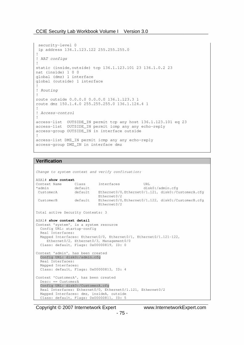
CCIE Security Lab Workbook Volume I Version 3.0
Copyright © 2007 Internetwork Expert www.InternetworkExpert.com- 75 -
security-level 0 ip address 136.1.123.122 255.255.255.0 !! NAT configs!static (inside,outside) tcp 136.1.123.101 23 136.1.0.2 23nat (inside) 1 0 0 global (dmz) 1 interface global (outside) 1 interface !! Routing!route outside 0.0.0.0 0.0.0.0 136.1.123.3 1 route dmz 150.1.4.0 255.255.255.0 136.1.124.4 1!! Access-control!access-list OUTSIDE_IN permit tcp any host 136.1.123.101 eq 23 access-list OUTSIDE_IN permit icmp any any echo-reply access-group OUTSIDE_IN in interface outside !access-list DMZ_IN permit icmp any any echo-reply access-group DMZ_IN in interface dmz
Verification
Change to system context and verify confiruation:
ASA1# show context Context Name Class Interfaces URL *admin default disk0:/admin.cfg CustomerA default Ethernet0/0,Ethernet0/1.121, disk0:/CustomerA.cfg Ethernet0/2 CustomerB default Ethernet0/0,Ethernet0/1.122, disk0:/CustomerB.cfg Ethernet0/2
Total active Security Contexts: 3
ASA1# show context detail Context "system", is a system resource Config URL: startup-config Real Interfaces: Mapped Interfaces: Ethernet0/0, Ethernet0/1, Ethernet0/1.121-122, Ethernet0/2, Ethernet0/3, Management0/0 Class: default, Flags: 0x00000819, ID: 0
Context "admin", has been created Config URL: disk0:/admin.cfg Real Interfaces: Mapped Interfaces: Class: default, Flags: 0x00000813, ID: 4
Context "CustomerA", has been created Desc: == CustomerA Config URL: disk0:/CustomerA.cfg Real Interfaces: Ethernet0/0, Ethernet0/1.121, Ethernet0/2 Mapped Interfaces: dmz, insideA, outside Class: default, Flags: 0x00000811, ID: 5

CCIE Security Lab Workbook Volume I Version 3.0
Copyright © 2007 Internetwork Expert www.InternetworkExpert.com- 76 -
Context "CustomerB", has been created Desc: == CustomerB Config URL: disk0:/CustomerB.cfg Real Interfaces: Ethernet0/0, Ethernet0/1.122, Ethernet0/2 Mapped Interfaces: dmz, insideB, outside Class: default, Flags: 0x00000811, ID: 6
Context "null", is a system resource Config URL: ... null ... Real Interfaces: Mapped Interfaces: Class: default, Flags: 0x00000809, ID: 257
Change to context “CustomerA”:
ASA1(config)# changeto context CustomerAASA1/CustomerA(config)#
R1#ping 150.1.4.4
Type escape sequence to abort. Sending 5, 100-byte ICMP Echos to 150.1.4.4, timeout is 2 seconds: !!!!!Success rate is 100 percent (5/5), round-trip min/avg/max = 1/3/4 ms R1#
ASA1/CustomerA(config)# show x6 in use, 6 most used PAT Global 136.1.123.100(80) Local 136.1.0.1(80)PAT Global 136.1.124.121(10) Local 136.1.0.1 ICMP id 5122PAT Global 136.1.124.121(9) Local 136.1.0.1 ICMP id 5121PAT Global 136.1.124.121(8) Local 136.1.0.1 ICMP id 5120PAT Global 136.1.124.121(7) Local 136.1.0.1 ICMP id 5119PAT Global 136.1.124.121(6) Local 136.1.0.1 ICMP id 5118
R3#ping 136.1.123.121
Type escape sequence to abort. Sending 5, 100-byte ICMP Echos to 136.1.123.121, timeout is 2 seconds: !!!!!Success rate is 100 percent (5/5), round-trip min/avg/max = 1/2/4 ms
R1#ping 136.1.123.3
Type escape sequence to abort. Sending 5, 100-byte ICMP Echos to 136.1.123.3, timeout is 2 seconds: !!!!!Success rate is 100 percent (5/5), round-trip min/avg/max = 4/4/8 ms
ASA1/CustomerA# show x6 in use, 6 most used PAT Global 136.1.123.100(80) Local 136.1.0.1(80)PAT Global 136.1.123.121(5) Local 136.1.0.1 ICMP id 5743PAT Global 136.1.123.121(4) Local 136.1.0.1 ICMP id 5742PAT Global 136.1.123.121(3) Local 136.1.0.1 ICMP id 5741PAT Global 136.1.123.121(2) Local 136.1.0.1 ICMP id 5740PAT Global 136.1.123.121(1) Local 136.1.0.1 ICMP id 5739
Test static mapping:
R3#telnet 136.1.123.100 80Trying 136.1.123.100, 80 ... Open

CCIE Security Lab Workbook Volume I Version 3.0
Copyright © 2007 Internetwork Expert www.InternetworkExpert.com- 77 -
GET / <HTML><HEAD><TITLE>R1 Home Page</TITLE></HEAD> <BODY BGCOLOR=#FFFFFF><H1>Cisco Systems</H1><H2>Accessing Cisco 2610 "R1"</H2>
Verify context CustomerB now:
ASA1/CustomerA(config)# changeto context CustomerBASA1/CustomerB(config)#
R2#ping 150.1.4.4
Type escape sequence to abort. Sending 5, 100-byte ICMP Echos to 150.1.4.4, timeout is 2 seconds: !!!!!Success rate is 100 percent (5/5), round-trip min/avg/max = 1/3/4 ms R2#
ASA1/CustomerB(config)# show x6 in use, 6 most used PAT Global 136.1.123.100(23) Local 136.1.0.1(23)PAT Global 136.1.124.122(5) Local 136.1.0.2 ICMP id 5691PAT Global 136.1.124.122(4) Local 136.1.0.2 ICMP id 5690PAT Global 136.1.124.122(3) Local 136.1.0.2 ICMP id 5689PAT Global 136.1.124.122(2) Local 136.1.0.2 ICMP id 5688PAT Global 136.1.124.122(1) Local 136.1.0.2 ICMP id 5687
R2#ping 136.1.123.3
Type escape sequence to abort. Sending 5, 100-byte ICMP Echos to 136.1.123.3, timeout is 2 seconds: !!!!!Success rate is 100 percent (5/5), round-trip min/avg/max = 1/3/8 ms
ASA1/CustomerB# show x6 in use, 6 most used PAT Global 136.1.123.101(23) Local 136.1.0.2(23)PAT Global 136.1.123.122(5) Local 136.1.0.2 ICMP id 9825PAT Global 136.1.123.122(4) Local 136.1.0.2 ICMP id 9824PAT Global 136.1.123.122(3) Local 136.1.0.2 ICMP id 9823PAT Global 136.1.123.122(2) Local 136.1.0.2 ICMP id 9822PAT Global 136.1.123.122(1) Local 136.1.0.2 ICMP id 9821
R3#ping 136.1.123.122
Type escape sequence to abort. Sending 5, 100-byte ICMP Echos to 136.1.123.122, timeout is 2 seconds: !!!!!Success rate is 100 percent (5/5), round-trip min/avg/max = 1/1/4 ms
R3#telnet 136.1.123.101Trying 136.1.123.101 ... Open
R2>

CCIE Security Lab Workbook Volume I Version 3.0
Copyright © 2007 Internetwork Expert www.InternetworkExpert.com- 78 -
Further Reading
Enabling Multiple Context ModeAdding and Managing Security Contexts

CCIE Security Lab Workbook Volume I Version 3.0
Copyright © 2007 Internetwork Expert www.InternetworkExpert.com- 79 -
Administrative Context and Resource Management
Objective: Configure device management with administrative context and control system resources allocation between contexts.
AAA/CAServer
Mgmt10.0.0.0/24 VLAN120
.12
R4
DMZ136.1.124.0/24 VLAN124
A: .121B: .122
.4
ASA1
R1 R2
R3
InsideB InsideA
Outside
136.1.0.0/24 VLAN122136.1.0.0/24 VLAN121
136.1.123.0/24 VLAN123
.12 .12
.3
.1 .2
R3
A: .121B: .122
Lo0: 150.1.4.4/24
Directions
Configure devices as per the scenario “PIX/ASA Firewall/Advanced Firewall” “Firewall Contexts Configuration”.
In order to manage the firewall configured in multiple contexts mode, you need to configure special “admin” context, which has the ability to access “system” context and configure the firewall.
ASA firewall permits setting limits for certain system resources, and assigning these limits to firewall contexts (virtual firewalls).
Create VLAN120 and configure the respective switchports. From system context do the following:
o Allocate the Management interface to default context “admin”, map it to name “management”.
o Create resource class named “Gold” as follows:
Limit number of Hosts and Xlates to 1000. Limit number of Connections to 10000.
o Create resource class named “Silver” as follows:
Limit number of Hosts and Xlates to 500.

CCIE Security Lab Workbook Volume I Version 3.0
Copyright © 2007 Internetwork Expert www.InternetworkExpert.com- 80 -
Limit number of Connections to 5000.
o Configure admin context to use class “default”. o Configure “CustomerA” context to use class “Gold”. o Configure “CustomerB” context to use class “Silver”
Change to context “admin” and configure as follows:
o Enable interface “management” and configure security-level 100 along with nameif “management”.
o Make interface management-only and configure IP address 10.0.0.12/24.
o Configure SSH/Telnet to accept connections from anywhere on management interface.
o Configure SSH/Telnet to be authenticated locally. o Create local user named ADMIN with password CISCO.
Final Configuration
SW1:vlan 120!interface Fa0/12 switchport host switchport access vlan 120 !interface Fa0/20 switchport host switchport access vlan 120
ASA1:admin-context admin context admin allocate-interface Management0/0 management config-url disk0:/admin.cfg !class Gold limit-resource Hosts 1000 limit-resource Xlates 1000 limit-resource Conns 10000 !class Silver limit-resource Hosts 500 limit-resource Conns 5000 limit-resource Xlates 500 !context admin member default !context CustomerA member Gold !context CustomerB member Silver

CCIE Security Lab Workbook Volume I Version 3.0
Copyright © 2007 Internetwork Expert www.InternetworkExpert.com- 81 -
!! Configure admin context !changeto context admin
interface management nameif management security-level 100 ip address 10.0.0.12 255.255.255.0 management-only !username ADMIN password CISCO encrypted !aaa authentication ssh console LOCALaaa authentication telnet console LOCAL!telnet 0 0 management ssh 0 0 management
Verification
From AAA/CA server test connectivity to the ASA:

CCIE Security Lab Workbook Volume I Version 3.0
Copyright © 2007 Internetwork Expert www.InternetworkExpert.com- 82 -
Further Reading
Enabling Multiple Context ModeAdding and Managing Security Contexts

CCIE Security Lab Workbook Volume I Version 3.0
Copyright © 2007 Internetwork Expert www.InternetworkExpert.com- 83 -
Active/Standby Stateful Failover with Failover Interface
Objective: Configure active/standby stateful failover.
ASA1
R1 R2
Inside
Outside
136.1.120.0/24 VLAN120
.1 .2
ASA2
RIPv2
136.1.110.0/24 VLAN110
.254
.254
.254
.254
E0/2
E0/2
Directions
Pre-configure devices as follows:
o Create VLANs 110 and 120, and configure the respective switchports.
o Configure IP addressing on R1 and R2 as per the diagram.
Configure the ASA1 unit as follows:
o Use hostname “ASA”. o Configure inside and outside interface IP addressing as per the
diagram.o Configure RIP as routing protocol. o Configure PAT for inside hosts going outside, using the outside
interface IP address.o Configure access-list OUTSIDE_IN to permit ICMP echo-reply
packets.o Apply access-group OUTSIDE_IN to interface outside.
Configure failover on the ASA1 as follows:
o Enable interface Ethernet0/2. o Configure unit as primary. o Enable LAN-based failover, using interface Ethernet 0/2 and name
“failover” for interface. o Configure stateful failover link using the same interface.

CCIE Security Lab Workbook Volume I Version 3.0
Copyright © 2007 Internetwork Expert www.InternetworkExpert.com- 84 -
o Configure IP addressing for failover link, using IP address 100.100.100.12 for primary and 100.100.100.13 for secondary unit, along with netmask 255.255.255.0.
o Enable failover, and configure monitoring for interfaces “inside” and “outside”.
o Set polling and hold timers for interface/unit polling to minimum values.
o Configure interface-policy to failover upon single interface failure.
Configure failover on the ASA2 unit as follows:
o Designate unit as secondary. o Enable interface Ethernet 0/2. o Enable LAN-based failover, using interface Ethernet 0/2 and name
“failover” for interface. o Configure stateful failover link using the same interface. o Configure IP addressing for failover link, using IP address
100.100.100.12 for primary and 100.100.100.13 for secondary unit, along with netmask 255.255.255.0.
o Enable failover, the primary unit should replicate it’s configuration.
Final Configuration
Pre-Configuration:
SW1:vlan 110,120,999 !interface Fa0/1 switchport host switchport access vlan 110 !interface Fa0/2 switchport host switchport access vlan 120 !interface Fa0/13 switchport host switchport access vlan 110 !interface Fa0/15 switchport host switchport access vlan 110 !interface Fa0/23 switchport trunk encaps dot1q switchport mode trunk
SW2:vlan 110,120,999 !

CCIE Security Lab Workbook Volume I Version 3.0
Copyright © 2007 Internetwork Expert www.InternetworkExpert.com- 85 -
interface Fa0/12 switchport host switchport access vlan 120 !interface Fa0/13 switchport host switchport access vlan 999 !interface Fa0/14 switchport host switchport access vlan 120 !interface Fa0/15 switchport host switchport access vlan 999 !interface Fa0/23 switchport trunk encaps dot1q switchport mode trunk
R1:interface Ethernet 0/0 no shut ip address 136.1.110.1 255.255.255.0 !router rip ver 2 no auto network 136.1.0.0
R2:interface Ethernet 0/0 no shut ip address 136.1.120.2 255.255.255.0 !router rip ver 2 no auto network 136.1.0.0
ASA1:!! Configure basic interface settings!interface Ethernet0/1 nameif inside ip address 136.1.110.254 255.255.255.0 no shutdown !interface Ethernet0/0 nameif outside ip address 136.1.120.254 255.255.255.0 no shutdown !router rip version 2 no auto-summary

CCIE Security Lab Workbook Volume I Version 3.0
Copyright © 2007 Internetwork Expert www.InternetworkExpert.com- 86 -
network 136.1.0.0 !nat-controlnat (inside) 1 0 0 global (outside) 1 interface
!! Access-control!access-list OUTSIDE_IN permit icmp any any echo-reply access-group OUTSIDE_IN in interface outside
!! Enable the failover interface!interface Ethernet0/2 no shut
!! Configure failover settings!failover lan unit primary failover lan interface failover Ethernet0/2 failover link failover Ethernet0/2 failover int ip failover 100.100.100.12 255.255.255.0 st 100.100.100.13 failover
!! Configure interface monitoring and failover policy!monitor-interface outside monitor-interface inside
!! Unit & interface polling!failover polltime unit msec 200 holdtime msec 800 failover polltime interface msec 500 holdtime 5
!failover interface-policy 1
ASA2:interface Ethernet0/2 no shut !failover lan unit secondary failover lan interface failover Ethernet0/2 failover link failover Ethernet0/2 failover int ip failover 100.100.100.12 255.255.255.0 st 100.100.100.13 failover

CCIE Security Lab Workbook Volume I Version 3.0
Copyright © 2007 Internetwork Expert www.InternetworkExpert.com- 87 -
Verification
Check the primary unit:
ASA(config)# show failover interface interface failover Ethernet0/2 System IP Address: 100.100.100.12 255.255.255.0 My IP Address : 100.100.100.12 Other IP Address : 100.100.100.13
ASA(config)# show failover Failover OnFailover unit Primary Failover LAN Interface: failover Ethernet0/2 (up) Unit Poll frequency 200 milliseconds, holdtime 800 milliseconds Interface Poll frequency 500 milliseconds, holdtime 5 seconds Interface Policy 1 Monitored Interfaces 2 of 250 maximum Version: Ours 7.2(2), Mate 7.2(2) Last Failover at: 05:58:31 UTC Feb 5 2007 This host: Primary - Active Active time: 3166 (sec) slot 0: ASA5510 hw/sw rev (1.1/7.2(2)) status (Up Sys) Interface inside (136.1.110.254): Normal (Waiting) Interface outside (136.1.120.254): Normal (Waiting) slot 1: empty Other host: Secondary - Standby Ready Active time: 331 (sec) slot 0: ASA5510 hw/sw rev (1.1/7.2(2)) status (Up Sys) Interface inside (0.0.0.0): Normal (Waiting) Interface outside (0.0.0.0): Normal (Waiting) slot 1: empty
Stateful Failover Logical Update Statistics Link : failover Ethernet0/2 (up) Stateful Obj xmit xerr rcv rerr General 335 0 331 0 sys cmd 332 0 332 0 up time 0 0 0 0 RPC services 0 0 0 0 TCP conn 0 0 0 0 UDP conn 0 0 0 0 ARP tbl 4 0 0 0 Xlate_Timeout 0 0 0 0 VPN IKE upd 0 0 0 0 VPN IPSEC upd 0 0 0 0 VPN CTCP upd 0 0 0 0 VPN SDI upd 0 0 0 0 VPN DHCP upd 0 0 0 0
Logical Update Queue Information Cur Max Total Recv Q: 0 2 422 Xmit Q: 0 2 2744
Check the standby unit:
ASA(config)# show failover Failover OnFailover unit Secondary Failover LAN Interface: failover Ethernet0/2 (up) Unit Poll frequency 200 milliseconds, holdtime 800 milliseconds

CCIE Security Lab Workbook Volume I Version 3.0
Copyright © 2007 Internetwork Expert www.InternetworkExpert.com- 88 -
Interface Poll frequency 500 milliseconds, holdtime 5 seconds Interface Policy 1 Monitored Interfaces 2 of 250 maximum Version: Ours 7.2(2), Mate 7.2(2) Last Failover at: 05:58:29 UTC Feb 5 2007 This host: Secondary - Standby Ready Active time: 331 (sec) slot 0: ASA5510 hw/sw rev (1.1/7.2(2)) status (Up Sys) Interface inside (0.0.0.0): Normal (Waiting) Interface outside (0.0.0.0): Normal (Waiting) slot 1: empty Other host: Primary - Active Active time: 3219 (sec) slot 0: ASA5510 hw/sw rev (1.1/7.2(2)) status (Up Sys) Interface inside (136.1.110.254): Normal (Waiting) Interface outside (136.1.120.254): Normal (Waiting) slot 1: empty
Stateful Failover Logical Update Statistics Link : failover Ethernet0/2 (up) Stateful Obj xmit xerr rcv rerr General 338 0 342 0 sys cmd 339 0 339 0 up time 0 0 0 0 RPC services 0 0 0 0 TCP conn 0 0 0 0 UDP conn 0 0 0 0 ARP tbl 0 0 4 0 Xlate_Timeout 0 0 0 0 VPN IKE upd 0 0 0 0 VPN IPSEC upd 0 0 0 0 VPN CTCP upd 0 0 0 0 VPN SDI upd 0 0 0 0 VPN DHCP upd 0 0 0 0
Logical Update Queue Information Cur Max Total Recv Q: 0 1 2805 Xmit Q: 0 1 429
Initiate a session from inside to outside:
R1#telnet 136.1.120.2Trying 136.1.120.2 ... Open
R2>show clock*06:26:10.444 UTC Fri Mar 5 1993
Introduce failure by shutting down switchport for outside interface:
SW2#conf tSW2(config)#int fa 0/12SW2(config-if)#shutSW2(config-if)#
Check the primary unit:
Rack1AS>12[Resuming connection 12 to asa1 ... ]
Switching to Standby
ASA(config)#

CCIE Security Lab Workbook Volume I Version 3.0
Copyright © 2007 Internetwork Expert www.InternetworkExpert.com- 89 -
Check our connection:
Rack1AS>1[Resuming connection 1 to r1 ... ]
R2>show clock*06:26:33.706 UTC Fri Mar 5 1993
ASA(config)# show failover Failover OnFailover unit Primary Failover LAN Interface: failover Ethernet0/2 (up) Unit Poll frequency 200 milliseconds, holdtime 800 milliseconds Interface Poll frequency 500 milliseconds, holdtime 5 seconds Interface Policy 1 Monitored Interfaces 2 of 250 maximum Version: Ours 7.2(2), Mate 7.2(2) Last Failover at: 06:15:49 UTC Feb 5 2007 This host: Primary - Failed Active time: 3883 (sec) slot 0: ASA5510 hw/sw rev (1.1/7.2(2)) status (Up Sys) Interface inside (0.0.0.0): Normal (Waiting) Interface outside (0.0.0.0): No Link (Waiting) slot 1: empty Other host: Secondary - Active Active time: 540 (sec) slot 0: ASA5510 hw/sw rev (1.1/7.2(2)) status (Up Sys) Interface inside (136.1.110.254): Normal (Waiting) Interface outside (136.1.120.254): Normal (Waiting) slot 1: empty
Stateful Failover Logical Update Statistics Link : failover Ethernet0/2 (up) Stateful Obj xmit xerr rcv rerr General 459 0 445 0 sys cmd 443 0 443 0 up time 0 0 0 0 RPC services 0 0 0 0 TCP conn 8 0 2 0 UDP conn 0 0 0 0 ARP tbl 8 0 0 0 Xlate_Timeout 0 0 0 0 VPN IKE upd 0 0 0 0 VPN IPSEC upd 0 0 0 0 VPN CTCP upd 0 0 0 0 VPN SDI upd 0 0 0 0 VPN DHCP upd 0 0 0 0
Logical Update Queue Information Cur Max Total Recv Q: 0 2 715 Xmit Q: 0 2 3541
Further Reading
Configuring Failover
Active Stateful Failover with Failover Interface

CCIE Security Lab Workbook Volume I Version 3.0
Copyright © 2007 Internetwork Expert www.InternetworkExpert.com- 90 -
Objective: Configure active/active failover with two firewall contexts.
ASA1
R1
R2
InsideB
Outside
136.1.130.0/24 VLAN130
.1
.3
ASA2
10.0.0.0/24 VLAN122.254
.254
A: .253B: .254
E0/2
E0/2
.2
R3
InsideA10.0.0.0/24 VLAN121
A: .253B: .254
Directions
The goal of this task is to create two virtual contexts, and configure each ASA unit to be active unit for a context, and standby for the other.
The key idea of Active/Active failover is that one ‘physical’ firewall unit can act as primary device for a group of contexts (virtual firewalls) and secondary for another group.
Each firewall unit may have priority configured for a group, along with preemption property. As soon as firewall detects a unit with a higher priority for a group, and preemption is enabled – the higher priority firewall takes the active role.
Pre-configuration:
o Create VLANs 121,122,123. Assign the respective switchports to these VLANs.
o Configure the switchport corresponding to the ASA1/ASA2 inside interfaces as 802.1q trunks.
o Configure IP addressing on routers as per the diagram.o Configure static default routes at R1 and R2 to point at 10.0.0.254.
Configure the ASA1 for virtual contexts as follows:
o Enable multiple-context mode and reboot into system context. o Residing in system context perform the following:
Configure hardware interfaces as follows:
Enable Ethernet 0/0, Ethernet 0/1. Configure two subinterfaces namely Ethernet0/1.121
and Ethernet0/1.122 for VLANs 121 and 122

CCIE Security Lab Workbook Volume I Version 3.0
Copyright © 2007 Internetwork Expert www.InternetworkExpert.com- 91 -
respectively on interface Ethernet 0/1.
Make sure you have context “admin” created, with configurl “disk0:/admin.cfg”. Enable it as admincontext. The admin context should be initialized before anything else could be configured.
Create context named “CustomerA” as follows:
Use configurl “disk0:/CustomerA.cfg” Allocate interfaces Ethernet0/1.121, Ethernet0/0 to
this context.
Create context named “CustomerB” as follows:
Use configurl “disk0:/CustomerB.cfg” Allocate interfaces Ethernet0/1.122, Ethernet0/0 to
this context.
Configure the ASA1 to be the primary failover unit as follows:
o Enable interface Ethernet0/2. o Configure unit as failover primary. o Enable LAN-based failover, using interface Ethernet 0/2 and name
“failover” for interface. o Configure stateful failover link using the same interface. o Configure IP addressing for failover link, using IP address
100.100.100.12 for primary and 100.100.100.13 for secondary unit, along with netmask 255.255.255.0.
o Create failover group 1, and configure the ASA1 as primary for the group. This group should preempt.
o Create failover group 2, and configure the ASA1 as secondary for the group. This group should preempt.
o Assign context “CustomerA” to failover group 1 and context “Customer B” to failover group 2.
o Enable failover.
Configure failover on the ASA2 unit as follows:
o Reboot unit into multiple context mode. o Designate unit as failover secondary. o Enable interface Ethernet 0/2. o Enable LAN-based failover, using interface Ethernet 0/2 and name
“failover” for interface. o Configure stateful failover link using the same interface.

CCIE Security Lab Workbook Volume I Version 3.0
Copyright © 2007 Internetwork Expert www.InternetworkExpert.com- 92 -
o Configure IP addressing for failover link, using IP address 100.100.100.12 for primary and 100.100.100.13 for secondary unit, along with netmask 255.255.255.0.
o Enable failover: the primary unit should replicate it’s configuration to the secondary.
Final Configuration
Pre-Configuration:
SW1:vlan 121,122,130 !interface Fa0/1 switchport host switchport access vlan 121 !interface Fa0/2 switchport host switchport access vlan 122 !interface Fa0/3 switchport host switchport access vlan 130 !interface Fa0/13 desc == ASA1 Inside switchport trunk encaps dot1q switchport mode trunk!interface Fa0/15 desc == ASA2 Inside switchport trunk encaps dot1q switchport mode trunk !interface Fa0/23 switchport trunk encaps dot1q switchport mode trunk
SW2:vlan 121,122,130 !interface Fa0/12 desc == ASA1 Outside switchport host switchport access vlan 130 !interface Fa0/14 desc == ASA2 Outside switchport host switchport access vlan 130 !interface Fa0/13 desc == ASA1 DMZ switchport host switchport access vlan 999 !interface Fa0/15 desc == ASA2 DMZ switchport host

CCIE Security Lab Workbook Volume I Version 3.0
Copyright © 2007 Internetwork Expert www.InternetworkExpert.com- 93 -
switchport access vlan 999 !interface Fa0/23 switchport trunk encaps dot1q switchport mode trunk
R1:interface E0/0 ip address 10.0.0.1 255.255.255.0 no shut !ip route 0.0.0.0 0.0.0.0 10.0.0.254
R2:interface E0/0 ip address 10.0.0.2 255.255.255.0 no shut !ip route 0.0.0.0 0.0.0.0 10.0.0.254
R3:interface E0/0 ip address 136.1.130.3 255.255.255.0
Failover configuration:
ASA1:hostname ASA !! Configure physical interfaces!interface Ethernet0/0 no shutdown !interface Ethernet0/1 no shutdown !interface Ethernet0/1.121 vlan 121 no shutdown !interface Ethernet0/1.122 vlan 122 no shutdown
!! Identify admin context first!admin-context admincontext admin config-url disk0:/admin.cfg
!! Create context CustomerA and add interface !context CustomerA description == CustomerA allocate-interface Ethernet0/0 allocate-interface Ethernet0/1.121

CCIE Security Lab Workbook Volume I Version 3.0
Copyright © 2007 Internetwork Expert www.InternetworkExpert.com- 94 -
config-url disk0:/CustomerA.cfg
!! Create context CustomerB !context CustomerB description == CustomerB allocate-interface Ethernet0/0 allocate-interface Ethernet0/1.122 config-url disk0:/CustomerB.cfg
!! Change to context CustomerA!changeto context CustomerA
!! Configure sec-leves & IP addressing for interfaces ! IP addresses you use at shared interfaces should! not overlap between contexts!interface Ethernet0/1.121 nameif inside security-level 100 ip address 10.0.0.254 255.255.255.0!interface Ethernet0/0 nameif outside security-level 0 ip address 136.1.130.253 255.255.255.0!! Configure static PAT on outside interface, ! again no overlaps between contexts !
!! Dynamic PAT on shared interface!nat (inside) 1 0 0 global (outside) 1 interface !! Basic access-list to permit pings from inside!access-list OUTSIDE_IN permit icmp any any echo-reply access-group OUTSIDE_IN in interface outside
!! Change to context “CustomerB” and configure similarly!changeto context CustomerB ! interface Ethernet0/1.122 nameif inside security-level 100 ip address 10.0.0.254 255.255.255.0!interface Ethernet0/0

CCIE Security Lab Workbook Volume I Version 3.0
Copyright © 2007 Internetwork Expert www.InternetworkExpert.com- 95 -
nameif outside security-level 0 ip address 136.1.130.254 255.255.255.0 !! NAT configs!nat (inside) 1 0 0 global (outside) 1 interface !! Access-control rules to permit pings!access-list OUTSIDE_IN permit icmp any any echo-reply access-group OUTSIDE_IN in interface outside
!! Failover configs follow!changeto system !! Enable the failover interface!interface Ethernet0/2 no shutdown !! Configure failover settings!failover lan unit primary failover lan interface failover Ethernet0/2 failover link failover Ethernet0/2 failover int ip failover 100.100.100.12 255.255.255.0 st 100.100.100.13 !failover group 1 primary preempt !failover group 2 secondary preempt !context CustomerA join-failover-group 1 !context CustomerB join-failover-group 2 !failover
ASA2:!! Enable failover interface!interface Ethernet0/2 no shut !failover lan unit secondaryfailover lan interface failover Ethernet0/2

CCIE Security Lab Workbook Volume I Version 3.0
Copyright © 2007 Internetwork Expert www.InternetworkExpert.com- 96 -
failover link failover Ethernet0/2 failover int ip failover 100.100.100.12 255.255.255.0 st 100.100.100.13 failover
Verification
Check the primary unit status:
ASA(config)# show failover Failover OnFailover unit Primary Failover LAN Interface: failover Ethernet0/2 (up) Unit Poll frequency 1 seconds, holdtime 15 seconds Interface Poll frequency 5 seconds, holdtime 25 seconds Interface Policy 1 Monitored Interfaces 2 of 250 maximum Version: Ours 7.2(2), Mate 7.2(2) Group 1 last failover at: 07:54:53 UTC Feb 5 2007 Group 2 last failover at: 08:01:52 UTC Feb 5 2007
This host: Primary Group 1 State: Active Active time: 1224 (sec) Group 2 State: Standby Ready Active time: 859 (sec)
slot 0: ASA5510 hw/sw rev (1.1/7.2(2)) status (Up Sys) CustomerA Interface inside (10.0.0.254): Normal (Not-Monitored) CustomerA Interface outside (136.1.130.253): Normal (Waiting) CustomerB Interface inside (0.0.0.0): Normal (Not-Monitored) CustomerB Interface outside (0.0.0.0): Normal (Waiting) slot 1: empty
Other host: Secondary Group 1 State: Standby Ready Active time: 1046 (sec) Group 2 State: Active Active time: 1411 (sec)
slot 0: ASA5510 hw/sw rev (1.1/7.2(2)) status (Up Sys) CustomerA Interface inside (0.0.0.0): Normal (Not-Monitored) CustomerA Interface outside (0.0.0.0): Normal (Waiting) CustomerB Interface inside (10.0.0.254): Normal (Not-Monitored) CustomerB Interface outside (136.1.130.254): Normal (Waiting) slot 1: empty
Stateful Failover Logical Update Statistics Link : failover Ethernet0/2 (up) Stateful Obj xmit xerr rcv rerr General 277 0 277 0 sys cmd 277 0 277 0 up time 0 0 0 0 RPC services 0 0 0 0 TCP conn 0 0 0 0 UDP conn 0 0 0 0 ARP tbl 0 0 0 0 Xlate_Timeout 0 0 0 0
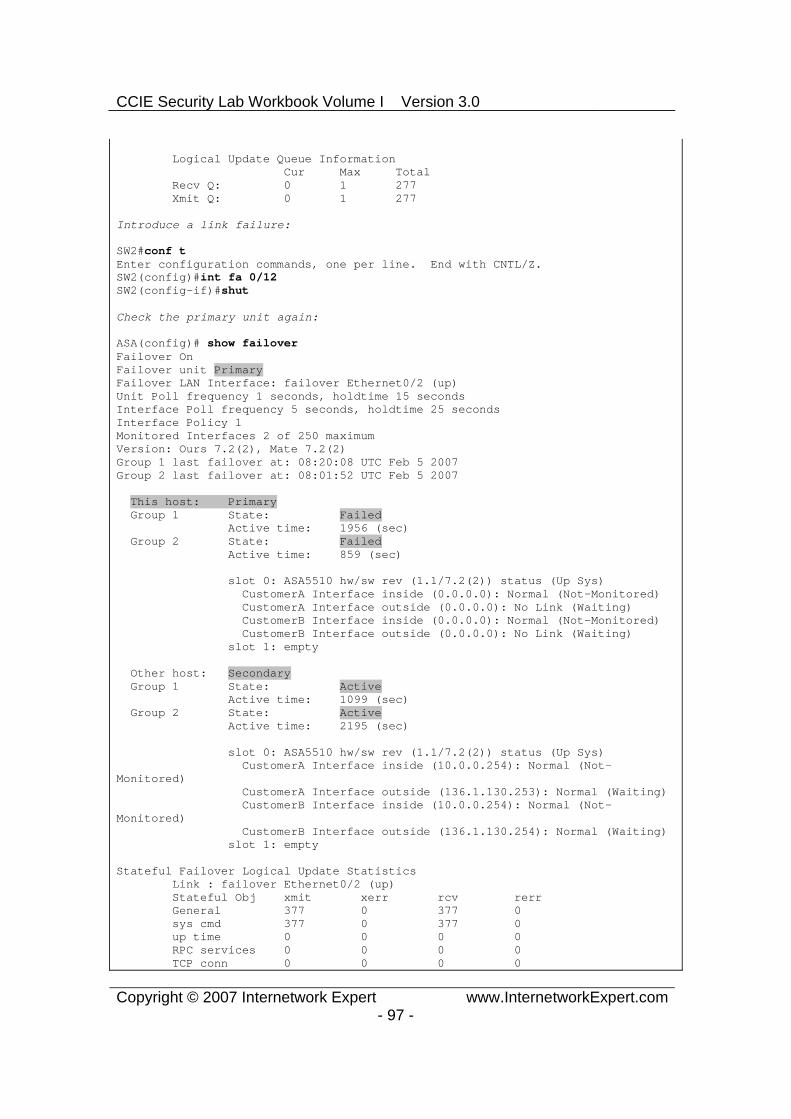
CCIE Security Lab Workbook Volume I Version 3.0
Copyright © 2007 Internetwork Expert www.InternetworkExpert.com- 97 -
Logical Update Queue Information Cur Max Total Recv Q: 0 1 277 Xmit Q: 0 1 277
Introduce a link failure:
SW2#conf tEnter configuration commands, one per line. End with CNTL/Z. SW2(config)#int fa 0/12SW2(config-if)#shut
Check the primary unit again:
ASA(config)# show failoverFailover OnFailover unit Primary Failover LAN Interface: failover Ethernet0/2 (up) Unit Poll frequency 1 seconds, holdtime 15 seconds Interface Poll frequency 5 seconds, holdtime 25 seconds Interface Policy 1 Monitored Interfaces 2 of 250 maximum Version: Ours 7.2(2), Mate 7.2(2) Group 1 last failover at: 08:20:08 UTC Feb 5 2007 Group 2 last failover at: 08:01:52 UTC Feb 5 2007
This host: Primary Group 1 State: Failed Active time: 1956 (sec) Group 2 State: Failed Active time: 859 (sec)
slot 0: ASA5510 hw/sw rev (1.1/7.2(2)) status (Up Sys) CustomerA Interface inside (0.0.0.0): Normal (Not-Monitored) CustomerA Interface outside (0.0.0.0): No Link (Waiting) CustomerB Interface inside (0.0.0.0): Normal (Not-Monitored) CustomerB Interface outside (0.0.0.0): No Link (Waiting) slot 1: empty
Other host: Secondary Group 1 State: Active Active time: 1099 (sec) Group 2 State: Active Active time: 2195 (sec)
slot 0: ASA5510 hw/sw rev (1.1/7.2(2)) status (Up Sys) CustomerA Interface inside (10.0.0.254): Normal (Not-Monitored) CustomerA Interface outside (136.1.130.253): Normal (Waiting) CustomerB Interface inside (10.0.0.254): Normal (Not-Monitored) CustomerB Interface outside (136.1.130.254): Normal (Waiting) slot 1: empty
Stateful Failover Logical Update Statistics Link : failover Ethernet0/2 (up) Stateful Obj xmit xerr rcv rerr General 377 0 377 0 sys cmd 377 0 377 0 up time 0 0 0 0 RPC services 0 0 0 0 TCP conn 0 0 0 0

CCIE Security Lab Workbook Volume I Version 3.0
Copyright © 2007 Internetwork Expert www.InternetworkExpert.com- 98 -
UDP conn 0 0 0 0 ARP tbl 0 0 0 0 Xlate_Timeout 0 0 0 0
Logical Update Queue Information Cur Max Total Recv Q: 0 1 377 Xmit Q: 0 1 377
Test connectivity:
R3#ping 136.1.130.253
Type escape sequence to abort. Sending 5, 100-byte ICMP Echos to 136.1.130.253, timeout is 2 seconds: .!!!!Success rate is 80 percent (4/5), round-trip min/avg/max = 1/2/4 ms
R3#ping 136.1.130.254
Type escape sequence to abort. Sending 5, 100-byte ICMP Echos to 136.1.130.254, timeout is 2 seconds: !!!!!Success rate is 100 percent (5/5), round-trip min/avg/max = 1/2/4 ms
R1#ping 136.1.130.3
Type escape sequence to abort. Sending 5, 100-byte ICMP Echos to 136.1.130.3, timeout is 2 seconds: !!!!!Success rate is 100 percent (5/5), round-trip min/avg/max = 1/2/4 ms
R2#ping 136.1.130.3
Type escape sequence to abort. Sending 5, 100-byte ICMP Echos to 136.1.130.3, timeout is 2 seconds: .!!!!Success rate is 80 percent (4/5), round-trip min/avg/max = 1/3/4 ms
Further Reading
Configuring Failover

CCIE Security Lab Workbook Volume I Version 3.0
Copyright © 2007 Internetwork Expert www.InternetworkExpert.com- 99 -
Monitoring Interfaces with Active/Active Failover
Objective: Configure interface monitoring with A/A failover.
ASA1
R1
R2
InsideB
Outside
136.1.130.0/24 VLAN130
.1
.3
ASA2
10.0.0.0/24 VLAN122.254
.254
A: .253B: .254
E0/2
E0/2
.2
R3
InsideA10.0.0.0/24 VLAN121
A: .253B: .254
Directions
Configure devices as per the “PIX/ASA Firewall/Advanced Firewall” scenario “Active/Active Stateful Failover with Failover Interface”
The goal of this task is to tune individual interface/unit monitoring parameters for failover groups.
Pick up the primary firewall unit for context “CustomerA” and “CustomerB” respectively, and configure as follows:
o Change to respective context. o Monitor both interface “inside” and “outside”.
Configure the primary failover unit (ASA1) as follows:
o Change to system context. o Change failover group 1 and group 2 interface polling timers to
minimum values. o Configure both groups interface-policy to failover upon double
monitored interface failure.
Final Configuration
Primary unit for CustomerA:changeto context CustomerA !monitor-interface inside monitor-interface outside
Primary unit for CustomerB:changeto context CustomerB !monitor-interface inside monitor-interface outside

CCIE Security Lab Workbook Volume I Version 3.0
Copyright © 2007 Internetwork Expert www.InternetworkExpert.com- 100 -
ASA1 (the primary failover unit):
failover group 1 interface-policy 2 polltime interface msec 500 holdtime 5 !failover group 2 interface-policy 2 polltime interface msec 500 holdtime 5
Verification
ASA(config)# changeto context CustomerAASA/CustomerA(config)# show monitor-interface This host: Secondary - Active Interface inside (10.0.0.254): Normal (Waiting) Interface outside (136.1.130.253): Normal (Waiting) Other host: Secondary - Standby Ready Interface inside (0.0.0.0): Normal (Waiting) Interface outside (0.0.0.0): Normal (Waiting)
ASA(config)# changeto context CustomerB ASA/CustomerB(config)# show monitor-interface This host: Secondary - Active Interface outside (0.0.0.0): Normal (Waiting) Interface inside (0.0.0.0): Normal (Waiting) Other host: Secondary - Standby Ready Interface outside (136.1.130.254): Normal (Waiting) Interface inside (10.0.0.254): Normal (Waiting)
ASA(config)# show failover Failover OnFailover unit Primary Failover LAN Interface: failover Ethernet0/2 (up) Unit Poll frequency 1 seconds, holdtime 15 seconds Interface Poll frequency 500 milliseconds, holdtime 5 seconds Interface Policy 1 Monitored Interfaces 4 of 250 maximum Version: Ours 7.2(2), Mate 7.2(2) Group 1 last failover at: 08:47:51 UTC Feb 5 2007 Group 2 last failover at: 08:01:52 UTC Feb 5 2007
This host: Primary Group 1 State: Active Active time: 3810 (sec) Group 2 State: Standby Ready Active time: 859 (sec)
slot 0: ASA5510 hw/sw rev (1.1/7.2(2)) status (Up Sys) CustomerA Interface inside (10.0.0.254): Normal (Waiting) CustomerA Interface outside (136.1.130.253): Normal (Waiting) CustomerB Interface inside (0.0.0.0): Normal (Waiting) CustomerB Interface outside (0.0.0.0): Normal (Waiting) slot 1: empty
Other host: Secondary Group 1 State: Standby Ready Active time: 2557 (sec) Group 2 State: Active Active time: 5507 (sec)
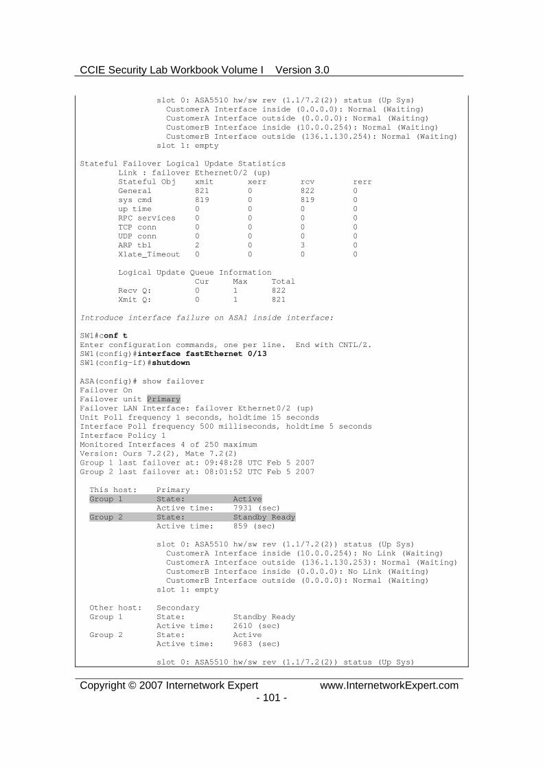
CCIE Security Lab Workbook Volume I Version 3.0
Copyright © 2007 Internetwork Expert www.InternetworkExpert.com- 101 -
slot 0: ASA5510 hw/sw rev (1.1/7.2(2)) status (Up Sys) CustomerA Interface inside (0.0.0.0): Normal (Waiting) CustomerA Interface outside (0.0.0.0): Normal (Waiting) CustomerB Interface inside (10.0.0.254): Normal (Waiting) CustomerB Interface outside (136.1.130.254): Normal (Waiting) slot 1: empty
Stateful Failover Logical Update Statistics Link : failover Ethernet0/2 (up) Stateful Obj xmit xerr rcv rerr General 821 0 822 0 sys cmd 819 0 819 0 up time 0 0 0 0 RPC services 0 0 0 0 TCP conn 0 0 0 0 UDP conn 0 0 0 0 ARP tbl 2 0 3 0 Xlate_Timeout 0 0 0 0
Logical Update Queue Information Cur Max Total Recv Q: 0 1 822 Xmit Q: 0 1 821
Introduce interface failure on ASA1 inside interface:
SW1#conf tEnter configuration commands, one per line. End with CNTL/Z. SW1(config)#interface fastEthernet 0/13SW1(config-if)#shutdown
ASA(config)# show failoverFailover OnFailover unit Primary Failover LAN Interface: failover Ethernet0/2 (up) Unit Poll frequency 1 seconds, holdtime 15 seconds Interface Poll frequency 500 milliseconds, holdtime 5 seconds Interface Policy 1 Monitored Interfaces 4 of 250 maximum Version: Ours 7.2(2), Mate 7.2(2) Group 1 last failover at: 09:48:28 UTC Feb 5 2007 Group 2 last failover at: 08:01:52 UTC Feb 5 2007
This host: Primary Group 1 State: Active Active time: 7931 (sec) Group 2 State: Standby Ready Active time: 859 (sec)
slot 0: ASA5510 hw/sw rev (1.1/7.2(2)) status (Up Sys) CustomerA Interface inside (10.0.0.254): No Link (Waiting) CustomerA Interface outside (136.1.130.253): Normal (Waiting) CustomerB Interface inside (0.0.0.0): No Link (Waiting) CustomerB Interface outside (0.0.0.0): Normal (Waiting) slot 1: empty
Other host: Secondary Group 1 State: Standby Ready Active time: 2610 (sec) Group 2 State: Active Active time: 9683 (sec)
slot 0: ASA5510 hw/sw rev (1.1/7.2(2)) status (Up Sys)

CCIE Security Lab Workbook Volume I Version 3.0
Copyright © 2007 Internetwork Expert www.InternetworkExpert.com- 102 -
CustomerA Interface inside (0.0.0.0): Normal (Waiting) CustomerA Interface outside (0.0.0.0): Normal (Waiting) CustomerB Interface inside (10.0.0.254): Normal (Waiting) CustomerB Interface outside (136.1.130.254): Normal (Waiting) slot 1: empty
Stateful Failover Logical Update Statistics Link : failover Ethernet0/2 (up) Stateful Obj xmit xerr rcv rerr General 1377 0 1378 0 sys cmd 1375 0 1375 0 up time 0 0 0 0 RPC services 0 0 0 0 TCP conn 0 0 0 0 UDP conn 0 0 0 0 ARP tbl 2 0 3 0 Xlate_Timeout 0 0 0 0
Logical Update Queue Information Cur Max Total Recv Q: 0 1 1378 Xmit Q: 0 1 1377
Fail outside interface of the ASA1:
SW2#conf tEnter configuration commands, one per line. End with CNTL/Z. SW2(config)#int fa 0/12SW2(config-if)#shutSW2(config-if)#
ASA(config)# show failFailover OnFailover unit Primary Failover LAN Interface: failover Ethernet0/2 (up) Unit Poll frequency 1 seconds, holdtime 15 seconds Interface Poll frequency 500 milliseconds, holdtime 5 seconds Interface Policy 1 Monitored Interfaces 4 of 250 maximum Version: Ours 7.2(2), Mate 7.2(2) Group 1 last failover at: 10:27:22 UTC Feb 5 2007 Group 2 last failover at: 08:01:52 UTC Feb 5 2007
This host: Primary Group 1 State: Failed Active time: 8024 (sec) Group 2 State: Failed Active time: 859 (sec)
slot 0: ASA5510 hw/sw rev (1.1/7.2(2)) status (Up Sys) CustomerA Interface inside (0.0.0.0): No Link (Waiting) CustomerA Interface outside (0.0.0.0): No Link (Waiting) CustomerB Interface inside (0.0.0.0): No Link (Waiting) CustomerB Interface outside (0.0.0.0): No Link (Waiting) slot 1: empty
Other host: Secondary Group 1 State: Active Active time: 2618 (sec) Group 2 State: Active Active time: 9783 (sec)
slot 0: ASA5510 hw/sw rev (1.1/7.2(2)) status (Up Sys)
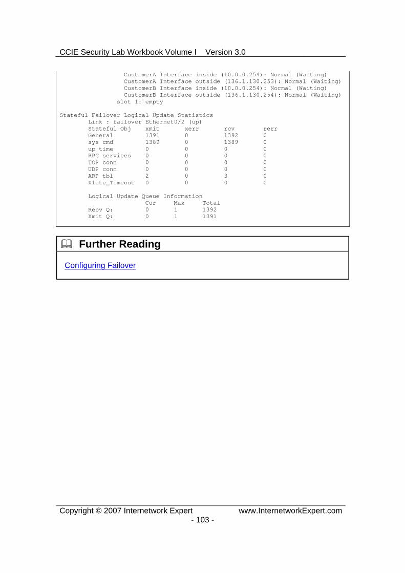
CCIE Security Lab Workbook Volume I Version 3.0
Copyright © 2007 Internetwork Expert www.InternetworkExpert.com- 103 -
CustomerA Interface inside (10.0.0.254): Normal (Waiting) CustomerA Interface outside (136.1.130.253): Normal (Waiting) CustomerB Interface inside (10.0.0.254): Normal (Waiting) CustomerB Interface outside (136.1.130.254): Normal (Waiting) slot 1: empty
Stateful Failover Logical Update Statistics Link : failover Ethernet0/2 (up) Stateful Obj xmit xerr rcv rerr General 1391 0 1392 0 sys cmd 1389 0 1389 0 up time 0 0 0 0 RPC services 0 0 0 0 TCP conn 0 0 0 0 UDP conn 0 0 0 0 ARP tbl 2 0 3 0 Xlate_Timeout 0 0 0 0
Logical Update Queue Information Cur Max Total Recv Q: 0 1 1392 Xmit Q: 0 1 1391
Further Reading
Configuring Failover

CCIE Security Lab Workbook Volume I Version 3.0
Copyright © 2007 Internetwork Expert www.InternetworkExpert.com- 104 -
Filtering with L2 Transparent Firewall
Objective: Configure Layer 2 transparent firewall
ASA1
R1
R2
AAA/CAServer
Inside Outside
Mgmt
136.X.12.0/24 VLAN122
R3.1
.2
.100
136.X.12.0/24 VLAN121
10.0.0.0/24 VLAN120
.12 .12
.12
Directions
Pre-Configuration:
o Create the required VLANs as per the diagram. Configure the respective switchports.
o Configure IP addressing on R1 and R2 as per the diagram.
Enable transparent firewall mode on the ASA unit. Configure the IP address 136.X.12.12/24 for the transparent firewall, and
configure the management interface. Configure the outside and inside interfaces. Permit telnet and pings from the lower security interface.
Final Configuration
ASA1:firewall transparent ip address 136.1.12.12 255.255.255.0 !interface Management 0/0 no shutdown ip address 10.0.0.12 255.255.255.0 !interface Ethernet 0/0

CCIE Security Lab Workbook Volume I Version 3.0
Copyright © 2007 Internetwork Expert www.InternetworkExpert.com- 105 -
no shut nameif outside !interface Ethernet 0/1 no shut nameif inside !! Access-List to apply to outside!access-list OUTSIDE_IN extended permit icmp any any echoaccess-list OUTSIDE_IN extended permit icmp any any echo-replyaccess-list OUTSIDE_IN extended permit tcp any any eq telnet!! Apply the ACLs !access-group OUTSIDE_IN in interface outside
SW1 & SW:vlan 120,121,122 !interface range Fa 0/21 - 23 switchport trunk encapsulation dot1q switchport mode trunk
SW1:!! Configure switchports!interface Fa 0/1 switchport host switchport access vlan 121 !interface Fa 0/2 switchport host switchport access vlan 122 !interface Fa 0/12 description == ASA Management switchport host switchport access vlan 120 !interface Fa 0/13 switchport host switchport access vlan 121 !interface Fa 0/20 switchport host switchport access vlan 120
SW2:!! Configure switchports!interface Fa 0/12 switchport host switchport access vlan 122
R1:interface Ethernet 0/0 no shut ip address 136.1.12.1 255.255.255.0
R2:

CCIE Security Lab Workbook Volume I Version 3.0
Copyright © 2007 Internetwork Expert www.InternetworkExpert.com- 106 -
interface Ethernet 0/0 no shut ip address 136.1.12.2 255.255.255.0
Verification
ASA1(config)# show mac-address-tableinterface mac address type Age(min) ------------------------------------------------------------------outside 0019.5684.9a0e dynamic 5inside 0019.5684.370f dynamic 5outside 0003.e335.1240 dynamic 2inside 0050.73f7.c0c0 dynamic 2
R1#ping 136.1.12.2
Type escape sequence to abort. Sending 5, 100-byte ICMP Echos to 136.1.12.2, timeout is 2 seconds: !!!!!Success rate is 100 percent (5/5), round-trip min/avg/max = 1/3/4 ms
R1#show ip arp Protocol Address Age (min) Hardware Addr Type Interface Internet 136.1.12.1 - 0050.73f7.c0c0 ARPA Ethernet0/0 Internet 136.1.12.2 71 0003.e335.1240 ARPA Ethernet0/0
R2#telnet 136.1.12.1Trying 136.1.12.1 ... Open
Password required, but none set
[Connection to 136.1.12.1 closed by foreign host]
R2#ping 136.1.12.12
Type escape sequence to abort. Sending 5, 100-byte ICMP Echos to 136.1.12.12, timeout is 2 seconds: .!!!!Success rate is 80 percent (4/5), round-trip min/avg/max = 1/2/4 ms
Further Reading
Firewall Mode Overview

CCIE Security Lab Workbook Volume I Version 3.0
Copyright © 2007 Internetwork Expert www.InternetworkExpert.com- 107 -
ARP Inspection with Transparent Firewall
Objective: Configure the transparent firewall to inspect ARP responses.
ASA1
R1
R2
AAA/CAServer
Inside Outside
Mgmt
136.X.12.0/24 VLAN122
R3.1
.2
.100
136.X.12.0/24 VLAN121
10.0.0.0/24 VLAN120
.12 .12
.12
Directions
Configure the devices as per the “PIX/ASA Firewall/Advanced Firewall” “Filtering with Layer 2 Transparent Firewall” scenario.
ARP inspection permits the firewall to check ARP responses for compliance, and prevent ARP spoofing.
Enable ARP inspection with “noflood” option on the ASA firewall. Create two static ARP entries for R1 and R2 routers.
Final Configuration
ASA1:arp outside 136.1.12.2 0003.e335.1240arp inside 136.1.12.1 0050.73f7.c0c0!arp-inspection outside enable no-flood arp-inspection inside enable no-flood
Verification
R1#show ip arpProtocol Address Age (min) Hardware Addr Type Interface Internet 136.1.12.1 - 0050.73f7.c0c0 ARPA Ethernet0/0 Internet 136.1.12.2 82 0003.e335.1240 ARPA Ethernet0/0
R2#conf tEnter configuration commands, one per line. End with CNTL/Z.

CCIE Security Lab Workbook Volume I Version 3.0
Copyright © 2007 Internetwork Expert www.InternetworkExpert.com- 108 -
R2(config)#int e 0/0R2(config-if)#mac-address 0003.e335.1241
R1#ping 136.1.12.2
Type escape sequence to abort. Sending 5, 100-byte ICMP Echos to 136.1.12.2, timeout is 2 seconds: .....Success rate is 0 percent (0/5)
R2(config-if)#mac-address 0003.e335.1240R2(config-if)#
R1#ping 136.1.12.2
Type escape sequence to abort. Sending 5, 100-byte ICMP Echos to 136.1.12.2, timeout is 2 seconds: !!!!!Success rate is 100 percent (5/5), round-trip min/avg/max = 1/3/4 ms
Further Reading
Configuring ARP Inspection
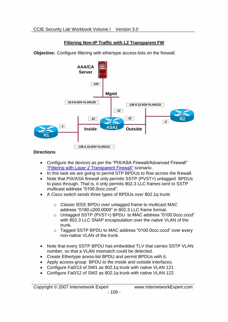
CCIE Security Lab Workbook Volume I Version 3.0
Copyright © 2007 Internetwork Expert www.InternetworkExpert.com- 109 -
Filtering Non-IP Traffic with L2 Transparent FW
Objective: Configure filtering with ethertype access-lists on the firewall.
ASA1
R1
R2
AAA/CAServer
Inside Outside
Mgmt
136.X.12.0/24 VLAN122
R3.1
.2
.100
136.X.12.0/24 VLAN121
10.0.0.0/24 VLAN120
.12 .12
.12
Directions
Configure the devices as per the “PIX/ASA Firewall/Advanced Firewall” “Filtering with Layer 2 Transparent Firewall” scenario.
In this task we are going to permit STP BPDUs to flow across the firewall. Note that PIX/ASA firewall only permits SSTP (PVST+) untagged BPDUs
to pass through. That is, it only permits 802.3 LLC frames sent to SSTP multicast address “0100.0ccc.cccd”.
A Cisco switch sends three types of BPDUs over 802.1q trunk:
o Classic IEEE BPDU over untagged frame to multicast MAC address “0180.c200.0000” in 802.3 LLC frame format.
o Untagged SSTP (PVST+) BPDU to MAC address “0100.0ccc.cccd” with 802.3 LLC SNAP encapsulation over the native VLAN of the trunk.
o Tagged SSTP BPDU to MAC address “0100.0ccc.cccd” over every non-native VLAN of the trunk.
Note that every SSTP BPDU has embedded TLV that carries SSTP VLAN number, so that a VLAN mismatch could be detected.
Create Ethertype acess-list BPDU and permit BPDUs with it. Apply access-group BPDU to the inside and outside interfaces. Configure Fa0/13 of SW1 as 802.1q trunk with native VLAN 121. Configure Fa0/12 of SW2 as 802.1q trunk with native VLAN 122.

CCIE Security Lab Workbook Volume I Version 3.0
Copyright © 2007 Internetwork Expert www.InternetworkExpert.com- 110 -
Final Configuration
SW1:inter Fa0/13 switchport trunk encaps dot1q switchport mode trunk switchport trunk native 121
SW2:inter Fa0/12 switchport trunk encaps dot1q switchport mode trunk switchport trunk native 122
ASA1:access-list BPDU ethertype permit bpdu
access-group BPDU in inter inside access-group BPDU in inter outside
Verification
ASA1(config)# show access-list BPDU access-list BPDU; 1 elements access-list BPDU ethertype permit bpdu (hitcount=98)
SW2:1d13h: %SPANTREE-2-RECV_PVID_ERR: Received BPDU with inconsistent peer vlan id 121 on FastEthernet0/12 VLAN122. 1d13h: %SPANTREE-2-BLOCK_PVID_LOCAL: Blocking FastEthernet0/12 on VLAN0122. Inconsistent local vlan.
SW1:1d13h: %SPANTREE-2-BLOCK_PVID_PEER: Blocking FastEthernet0/13 on VLAN0122. Inconsistent peer vlan. 1d13h: %SPANTREE-2-BLOCK_PVID_LOCAL: Blocking FastEthernet0/13 on VLAN0121. Inconsistent local vlan.
Further Reading
Configuring ARP Inspection

CCIE Security Lab Workbook Volume I Version 3.0
Copyright © 2007 Internetwork Expert www.InternetworkExpert.com- 111 -
Handling Fragmented Traffic
Objective: Tune the firewall fragment inspection parameters.
ASA1
R1
R2
AAA/CAServer
Inside Outside
DMZ
136.X.122.0/24 VLAN122
R3.1
.2
.100
136.X.121.0/24 VLAN121
10.0.0.0/24 VLAN120
.12 .12
.12
RIPv2
Directions
Configure devices as per the scenario “PIX/ASA Firewall/Access Control” ”Common Configuration”.
Permit ICMP traffic through the firewall. Disable the fragmented packets on all interfaces.
Final Configuration
ASA1:access-list OUTSIDE_IN permit icmp any any !access-group OUTSIDE_IN in interface outside !! Disable Fragment reassebly on all interfaces!fragment chain 1 inside fragment chain 1 outside fragment chain 1 dmz

CCIE Security Lab Workbook Volume I Version 3.0
Copyright © 2007 Internetwork Expert www.InternetworkExpert.com- 112 -
Verification
R1#ping 136.1.122.2 size 1500
Type escape sequence to abort. Sending 5, 1500-byte ICMP Echos to 136.1.122.2, timeout is 2 seconds: !!!!!Success rate is 100 percent (5/5), round-trip min/avg/max = 8/9/13 ms
R1#ping 136.1.122.2 size 1510
Type escape sequence to abort. Sending 5, 1510-byte ICMP Echos to 136.1.122.2, timeout is 2 seconds: .....Success rate is 0 percent (0/5)
R2#ping 136.1.121.1
Type escape sequence to abort. Sending 5, 100-byte ICMP Echos to 136.1.121.1, timeout is 2 seconds: !!!!!Success rate is 100 percent (5/5), round-trip min/avg/max = 1/2/4 ms
R2#ping 136.1.121.1 size 1510
Type escape sequence to abort. Sending 5, 1510-byte ICMP Echos to 136.1.121.1, timeout is 2 seconds: .....Success rate is 0 percent (0/5)
Further Reading
Configuring Fragment Size

CCIE Security Lab Workbook Volume I Version 3.0
Copyright © 2007 Internetwork Expert www.InternetworkExpert.com- 113 -
Handling Some Application Issues
Objective: Configure the firewall to handle certain application issues.
ASA1
R1
R2
AAA/CAServer
Inside Outside
DMZ
136.X.122.0/24 VLAN122
R3.1
.2
.100
136.X.121.0/24 VLAN121
10.0.0.0/24 VLAN120
.12 .12
.12
RIPv2
Directions
Configure devices as per the scenario “PIX/ASA Firewall/Access Control” ”Common Configuration”.
The first polular issue usually arise with DNS doctoring scenarios, where the PIX/ASA firewall is configured, for instance, with “alias” command.
Here is the short description:
o Consider server on inside with IP 136.1.121.100 mapped with static command to outside IP 136.1.122.100.
o Consider DNS server on outside, answering DNS queries to server domain name with outside IP 136.1.122.100.
o Configure “alias (inside) 136.1.121.100 136.1.122.100 255.255.255.255” to perform DNS doctoring.
o With this configuration PIX will start responding to ARP queries for 136.1.121.100 on inside interface.
o Configure “sysopt noproxyarp inside” to handle this issue. Note that this cammand disables all proxy ARP replies on mentioned interface.
The second issue commonly arise when inside users try to send e-mail through the PIX/ASA firewall or connect to external FTP servers. Some

CCIE Security Lab Workbook Volume I Version 3.0
Copyright © 2007 Internetwork Expert www.InternetworkExpert.com- 114 -
SMTP/FTP servers may send back the IDENT query over new TCP connection, which is blackholed at the firewall outside interface by default.
This may cause very long wating on connection startup. To remedy such situation you should do the following:
o For inside users, accessing the outside via dynamic NAT configuration (NAT pool on the firewall) configure “service resetoutside” command.
o To handle this issue for inside SMTP server (statically mapped, or bypassing NAT), configure “service resetinbound” command.
Final Configuration
ASA1:static (i,o) 136.1.122.100 136.1.121.100
!! DNS doctoring with alias!alias (inside) 136.1.121.100 136.1.122.100
!! Disable proxy-ARP on inside!sysopt noproxyarp inside
!! Reset TCP connections denied on outside interface! or denied inbound.!service resetinbound service resetoutside
Further Reading
PIX Performance Issues Caused by IDENT ProtocolUnderstanding the alias Command for the Cisco Secure PIX Firewall

CCIE Security Lab Workbook Volume I Version 3.0
Copyright © 2007 Internetwork Expert www.InternetworkExpert.com- 115 -
BGP Through the PIX/ASA Firewall
Objective: Configure BGP session through the PIX/ASA firewall.
ASA1
R1
R2
AAA/CAServer
Inside Outside
DMZ
136.X.122.0/24 VLAN122
R3.1
.2
.100
136.X.121.0/24 VLAN121
10.0.0.0/24 VLAN120
.12 .12
.12
RIPv2
BGP AS 1
BGP AS 2
Lo1: 192.168.1.1/24
Directions
Configure devices as per the scenario “PIX/ASA Firewall/Access Control” ”Common Configuration”.
Pre-Configure as follows:
o Create Loopback1 interface on R1. o Configure outside interface as RIP passive on the firewall. o Configure static NAT mapping of 136.X.121.1 to 136.X.122.1.
Configure BGP on R1 and R2 as per the diagram, using the following guidelines.
o Peer R1 and R2 using the ethernet interfaces IP addresses.o Use static NAT mapping for R1 to peer from R2. o Enable eBGP multihop for peering.
Adverties Loopback1 of R1 into BGP. To provide the transit connectivty through the firewall, advertise it into RIP as well.
Create and apply access-list on outside interface to permit pings to 192.168.1.0/24.
Create and apply route-map NEXT_HOP on R2 to set IP next-hop to 136.X.122.1 for updates received from R1.

CCIE Security Lab Workbook Volume I Version 3.0
Copyright © 2007 Internetwork Expert www.InternetworkExpert.com- 116 -
Final Configuration
R1:interface Loopback 1 ip address 192.168.1.1 255.255.255.0 !! BGP configuration!router bgp 1 neighbor 136.1.122.2 remote-as 2 neighbor 136.1.122.2 ebgp network 192.168.1.0 mask 255.255.255.0 !! Advertise loopback into RIP!router rip network 192.168.1.0
R2:!! route-map to change next-hop!route-map NEXT_HOP set ip next-hop 136.1.122.1 !router bgp 2 neighbor 136.1.122.1 remote-as 1 neighbor 136.1.122.1 ebgp neighbor 136.1.122.1 route-map NEXT_HOP in
ASA1:!! Static & ACL to permit inbound pings!static (inside,outside) 136.1.122.1 136.1.121.1 access-list OUTSIDE_IN permit icmp any 192.168.1.0 255.255.255.0 access-group OUTSIDE_IN in interface outside !! Prevent R2 from learning routes from the ASA!router rip passive-interface outside
Verification
R2#show ip bgp summary BGP router identifier 192.168.5.2, local AS number 2 BGP table version is 2, main routing table version 2 1 network entries using 101 bytes of memory 1 path entries using 48 bytes of memory 1 BGP path attribute entries using 60 bytes of memory 1 BGP AS-PATH entries using 24 bytes of memory 0 BGP route-map cache entries using 0 bytes of memory 0 BGP filter-list cache entries using 0 bytes of memory BGP using 233 total bytes of memory BGP activity 3/2 prefixes, 3/2 paths, scan interval 60 secs

CCIE Security Lab Workbook Volume I Version 3.0
Copyright © 2007 Internetwork Expert www.InternetworkExpert.com- 117 -
Neighbor V AS MsgRcvd MsgSent TblVer InQ OutQ Up/Down State/PfxRcd 136.1.122.1 4 1 19 16 2 0 0 00:02:01 1
R2#sh ip bgpBGP table version is 2, local router ID is 192.168.5.2 Status codes: s suppressed, d damped, h history, * valid, > best, i - internal, r RIB-failure, S Stale Origin codes: i - IGP, e - EGP, ? - incomplete
Network Next Hop Metric LocPrf Weight Path *> 192.168.1.0 136.1.122.1 0 0 1 i
R2# ping 192.168.1.1
Type escape sequence to abort. Sending 5, 100-byte ICMP Echos to 192.168.1.1, timeout is 2 seconds: !!!!!Success rate is 100 percent (5/5), round-trip min/avg/max = 4/4/4 ms
Further Reading
Sample Configurations of BGP Across a PIX Firewall

CCIE Security Lab Workbook Volume I Version 3.0
Copyright © 2007 Internetwork Expert www.InternetworkExpert.com- 118 -
Multicast Routing across the PIX/ASA Firewall
Objective: Configure stub multicast router feature on the PIX/ASA firewall.
ASA1
R1
R2
AAA/CAServer
Inside Outside
DMZ
136.X.122.0/24 VLAN122
R3.1
.2
.100
136.X.121.0/24 VLAN121
10.0.0.0/24 VLAN120
.12 .12
.12
RIPv2
Directions
Configure devices as per the scenario “PIX/ASA Firewall/Access Control” ”Common Configuration”.
In this task the goal is to make R1 hear multicast source at R2. We assume that the firewall and R2 are capable of communicating via PIM, therefore allowing for scalable multicast deployment.
Configure the firewall as follows:
o Enable multicast routing on the firewall. o Enable PIM on outside interface. o Configure RP address 150.1.2.2 o Limit IGMP on inside interface to 100 participants maximum. o Permit ICMP packets from the outside.
Configure R2 as follows:
o Enable multicast routing. o Create new Loopback0 interface with IP address 150.1.2.2/24. o Enable PIM Sparse-mode on Loopback0 and Ethernet 0/0. o Configure RP address to 150.1.2.2.

CCIE Security Lab Workbook Volume I Version 3.0
Copyright © 2007 Internetwork Expert www.InternetworkExpert.com- 119 -
On R1, join Ethernet 0/0 to group 239.0.0.1.
Final Configuration
ASA1:!! Enable multicast routing and PIM!multicast-routing!interface E 0/0 pim !! Configure IGMP on the inside!interface E0/1 igmp version 2 igmp limit 100 !! Configure the RP!pim rp-address 150.1.2.2 !! Permit ICMP traffic from R2!access-list OUTSIDE_IN permit icmp any any !access-group OUTSIDE_IN in interface outside
R2:ip multicat-routing !! Enable PIM on ethernet interface!interface Ethernet0/0 ip pim sparse-mode !interface Loopback0 ip address 150.1.2.2 255.255.255.0 ip pim sparse-mode !ip pim rp-address 150.1.2.2 !router rip network 150.1.0.0
R1:interface Ethernet 0/0 ip igmp join 239.0.0.1
Verification
ASA1(config)# show pim neighbor
Neighbor Address Interface Uptime Expires DR pri Bidir
136.1.122.2 outside 00:16:26 00:01:33 1
ASA1(config)# show mroute

CCIE Security Lab Workbook Volume I Version 3.0
Copyright © 2007 Internetwork Expert www.InternetworkExpert.com- 120 -
Multicast Routing Table Flags: D - Dense, S - Sparse, B - Bidir Group, s - SSM Group, C - Connected, L - Local, I - Received Source Specific Host Report, P - Pruned, R - RP-bit set, F - Register flag, T - SPT-bit set, J - Join SPTTimers: Uptime/Expires Interface state: Interface, State
(*, 224.0.1.40), 00:17:52/never, RP 0.0.0.0, flags: DPC Incoming interface: Null RPF nbr: 0.0.0.0 Outgoing interface list: outside, Null, 00:17:52/never
(*, 239.0.0.1), 00:15:59/never, RP 150.1.2.2, flags: SCJ Incoming interface: outside RPF nbr: 136.1.122.2 Outgoing interface list: inside, Forward, 00:15:59/never
R2#show ip mroute IP Multicast Routing Table Flags: D - Dense, S - Sparse, B - Bidir Group, s - SSM Group, C - Connected, L - Local, P - Pruned, R - RP-bit set, F - Register flag, T - SPT-bit set, J - Join SPT, M - MSDP created entry, X - Proxy Join Timer Running, A - Candidate for MSDP Advertisement, U - URD, I - Received Source Specific Host Report, Z - Multicast Tunnel Y - Joined MDT-data group, y - Sending to MDT-data group Outgoing interface flags: H - Hardware switched Timers: Uptime/Expires Interface state: Interface, Next-Hop or VCD, State/Mode
(*, 239.0.0.1), 00:16:36/00:02:48, RP 150.1.2.2, flags: S Incoming interface: Null, RPF nbr 0.0.0.0 Outgoing interface list: Ethernet0/0, Forward/Sparse, 00:16:36/00:02:48
(*, 224.0.1.40), 00:21:07/00:02:29, RP 150.1.2.2, flags: SPL Incoming interface: Null, RPF nbr 0.0.0.0 Outgoing interface list: Null
R2#ping 239.0.0.1
Type escape sequence to abort. Sending 1, 100-byte ICMP Echos to 239.0.0.1, timeout is 2 seconds:
Reply to request 0 from 136.1.121.1, 8 ms Reply to request 0 from 136.1.121.1, 24 ms
There are two response since we have configured two PIM interfaces.
R2#show ip mroute IP Multicast Routing Table Flags: D - Dense, S - Sparse, B - Bidir Group, s - SSM Group, C - Connected, L - Local, P - Pruned, R - RP-bit set, F - Register flag, T - SPT-bit set, J - Join SPT, M - MSDP created entry, X - Proxy Join Timer Running, A - Candidate for MSDP Advertisement, U - URD, I - Received Source Specific Host Report, Z - Multicast Tunnel Y - Joined MDT-data group, y - Sending to MDT-data group Outgoing interface flags: H - Hardware switched Timers: Uptime/Expires Interface state: Interface, Next-Hop or VCD, State/Mode

CCIE Security Lab Workbook Volume I Version 3.0
Copyright © 2007 Internetwork Expert www.InternetworkExpert.com- 121 -
(*, 239.0.0.1), 00:17:07/stopped, RP 150.1.2.2, flags: S Incoming interface: Null, RPF nbr 0.0.0.0 Outgoing interface list: Ethernet0/0, Forward/Sparse, 00:17:07/00:03:17
(136.1.122.2, 239.0.0.1), 00:00:04/00:02:55, flags: P Incoming interface: Ethernet0/0, RPF nbr 0.0.0.0 Outgoing interface list: Null
(150.1.2.2, 239.0.0.1), 00:00:04/00:03:29, flags: T Incoming interface: Loopback0, RPF nbr 0.0.0.0 Outgoing interface list: Ethernet0/0, Forward/Sparse, 00:00:05/00:03:24
(*, 224.0.1.40), 00:21:39/00:02:58, RP 150.1.2.2, flags: SPL Incoming interface: Null, RPF nbr 0.0.0.0 Outgoing interface list: Null
R2#
ASA1(config)# show mroute
Multicast Routing Table Flags: D - Dense, S - Sparse, B - Bidir Group, s - SSM Group, C - Connected, L - Local, I - Received Source Specific Host Report, P - Pruned, R - RP-bit set, F - Register flag, T - SPT-bit set, J - Join SPTTimers: Uptime/Expires Interface state: Interface, State
(*, 224.0.1.40), 00:19:10/never, RP 0.0.0.0, flags: DPC Incoming interface: Null RPF nbr: 0.0.0.0 Outgoing interface list: outside, Null, 00:19:10/never
(*, 239.0.0.1), 00:17:17/never, RP 150.1.2.2, flags: SCJ Incoming interface: outside RPF nbr: 136.1.122.2 Outgoing interface list: inside, Forward, 00:17:17/never
(136.1.122.2, 239.0.0.1), 00:00:14/00:03:15, flags: SFJT Incoming interface: outside RPF nbr: 136.1.122.2 Immediate Outgoing interface list: Null
(150.1.2.2, 239.0.0.1), 00:00:14/00:03:15, flags: SJT Incoming interface: outside RPF nbr: 136.1.122.2 Immediate Outgoing interface list: Null

CCIE Security Lab Workbook Volume I Version 3.0
Copyright © 2007 Internetwork Expert www.InternetworkExpert.com- 122 -
Further Reading
Configuring Multicast Routing

CCIE Security Lab Workbook Volume I Version 3.0
Copyright © 2007 Internetwork Expert www.InternetworkExpert.com- 123 -
System Monitoring
Objective: Configure Syslog and SNMP services on the ASA firewall.
ASA1
R1
R2
AAA/CAServer
Inside Outside
DMZ
136.X.122.0/24 VLAN122
R3.1
.2
.100
136.X.121.0/24 VLAN121
10.0.0.0/24 VLAN120
.12 .12
.12
RIPv2
Directions
Configure devices as per the scenario “PIX/ASA Firewall/Access Control” ”Common Configuration”.
Configure logging on the firewall as follows:
o Enable logging timestamps. o Configure logging levels:
Debugging for log buffer. Informational for syslog. Critical for telnet monitor. Alerts for Console.
o Configure logging buffer-size of 65536. o Configure logging to syslog host:
Host IP 10.0.0.100 on DMZ interface. Facility 23.
o Enable buffer save on wraps via FTP as follows:

CCIE Security Lab Workbook Volume I Version 3.0
Copyright © 2007 Internetwork Expert www.InternetworkExpert.com- 124 -
Use FTP server 10.0.0.100, root directory. Username anonymous Password [email protected]
o Enable logging globally.
Confiugure SNMP as follows:
o Deny SNMP version 1. Use snmp-map for this task. o Send all SNMP traps to DMZ host 10.0.0.100. o Configure SNMP server community to CISCO. o Configure SNMP server location to “Reno,NV”.
Final Configuration
ASA1:!! Logging Config!logging timestamp logging buffer-size 65536 logging console alerts logging monitor critical logging buffered debugging logging trap informational logging facility 23 logging host dmz 10.0.0.100 !logging ftp-bufferwrap logging ftp-server 10.0.0.100 / anonymous [email protected]!logging on !! Configure SNMP!snmp-server host dmz 10.0.0.100 trap community CISCO snmp-server location Reno,NV snmp-server community CISCO snmp-server enable traps all !! Create snmp-map to deny SNMP version 1!snmp-map asa_snmp_map deny version 1 !! Apply the map to the global policy!policy-map global_policy class inspection_default inspect snmp asa_snmp_map !! Configure NTP!ntp authentication-key 1 md5 CISCO ntp authenticate ntp server 136.1.121.1 key 1

CCIE Security Lab Workbook Volume I Version 3.0
Copyright © 2007 Internetwork Expert www.InternetworkExpert.com- 125 -
R1:ntp master ntp authentication-key 1 md5 CISCO
Verification
AAA/CA Server:
Start tftpd32 application to listen to syslog messages:
Further Reading
Monitoring the Security Appliance

CCIE Security Lab Workbook Volume I Version 3.0
Copyright © 2007 Internetwork Expert www.InternetworkExpert.com- 126 -
DHCP Server
Objective: Configure the PIX/ASA firewall to support dynamic client configuration.
ASA1
R1
R2
AAA/CAServer
Inside Outside
DMZ
136.X.122.0/24 VLAN122
R3.1
.2
.100
136.X.121.0/24 VLAN121
10.0.0.0/24 VLAN120
.12 .12
.12
RIPv2
Directions
Configure devices as per the scenario “PIX/ASA Firewall/Access Control” ”Common Configuration”.
It is possible to configure the PIX/ASA firewall to function as DHCP server (as well as DHCP relay).
The configuration steps are as follows:
o Configure DHCP to use address-range 136.X.121.100-136.X.121.254 on the inside interface.
o Configure DHCP to assign domainname “internetworkexpert.com” to clients.
o Configure DHCP lease duration of 30 minutes (1800 seconds). o Enable DHCP process on the inside interface.
Configure R1 to obtain an IP address via DHCP on its Ethernet interface.
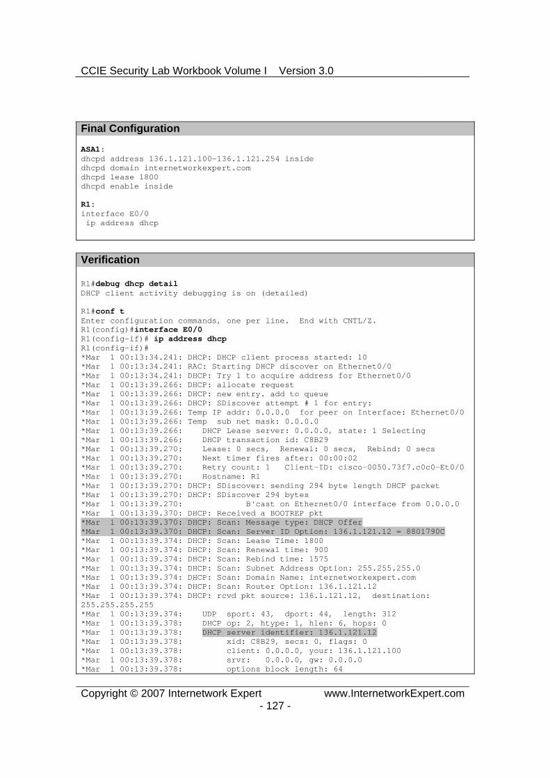
CCIE Security Lab Workbook Volume I Version 3.0
Copyright © 2007 Internetwork Expert www.InternetworkExpert.com- 127 -
Final Configuration
ASA1:dhcpd address 136.1.121.100-136.1.121.254 insidedhcpd domain internetworkexpert.com dhcpd lease 1800dhcpd enable inside
R1:interface E0/0 ip address dhcp
Verification
R1#debug dhcp detail DHCP client activity debugging is on (detailed)
R1#conf tEnter configuration commands, one per line. End with CNTL/Z. R1(config)#interface E0/0R1(config-if)# ip address dhcpR1(config-if)#*Mar 1 00:13:34.241: DHCP: DHCP client process started: 10 *Mar 1 00:13:34.241: RAC: Starting DHCP discover on Ethernet0/0 *Mar 1 00:13:34.241: DHCP: Try 1 to acquire address for Ethernet0/0 *Mar 1 00:13:39.266: DHCP: allocate request *Mar 1 00:13:39.266: DHCP: new entry. add to queue *Mar 1 00:13:39.266: DHCP: SDiscover attempt # 1 for entry: *Mar 1 00:13:39.266: Temp IP addr: 0.0.0.0 for peer on Interface: Ethernet0/0 *Mar 1 00:13:39.266: Temp sub net mask: 0.0.0.0 *Mar 1 00:13:39.266: DHCP Lease server: 0.0.0.0, state: 1 Selecting *Mar 1 00:13:39.266: DHCP transaction id: C8B29 *Mar 1 00:13:39.270: Lease: 0 secs, Renewal: 0 secs, Rebind: 0 secs *Mar 1 00:13:39.270: Next timer fires after: 00:00:02 *Mar 1 00:13:39.270: Retry count: 1 Client-ID: cisco-0050.73f7.c0c0-Et0/0 *Mar 1 00:13:39.270: Hostname: R1 *Mar 1 00:13:39.270: DHCP: SDiscover: sending 294 byte length DHCP packet *Mar 1 00:13:39.270: DHCP: SDiscover 294 bytes*Mar 1 00:13:39.270: B'cast on Ethernet0/0 interface from 0.0.0.0 *Mar 1 00:13:39.370: DHCP: Received a BOOTREP pkt *Mar 1 00:13:39.370: DHCP: Scan: Message type: DHCP Offer *Mar 1 00:13:39.370: DHCP: Scan: Server ID Option: 136.1.121.12 = 8801790C *Mar 1 00:13:39.374: DHCP: Scan: Lease Time: 1800 *Mar 1 00:13:39.374: DHCP: Scan: Renewal time: 900 *Mar 1 00:13:39.374: DHCP: Scan: Rebind time: 1575 *Mar 1 00:13:39.374: DHCP: Scan: Subnet Address Option: 255.255.255.0 *Mar 1 00:13:39.374: DHCP: Scan: Domain Name: internetworkexpert.com *Mar 1 00:13:39.374: DHCP: Scan: Router Option: 136.1.121.12 *Mar 1 00:13:39.374: DHCP: rcvd pkt source: 136.1.121.12, destination:255.255.255.255*Mar 1 00:13:39.374: UDP sport: 43, dport: 44, length: 312 *Mar 1 00:13:39.378: DHCP op: 2, htype: 1, hlen: 6, hops: 0 *Mar 1 00:13:39.378: DHCP server identifier: 136.1.121.12 *Mar 1 00:13:39.378: xid: C8B29, secs: 0, flags: 0 *Mar 1 00:13:39.378: client: 0.0.0.0, your: 136.1.121.100 *Mar 1 00:13:39.378: srvr: 0.0.0.0, gw: 0.0.0.0 *Mar 1 00:13:39.378: options block length: 64
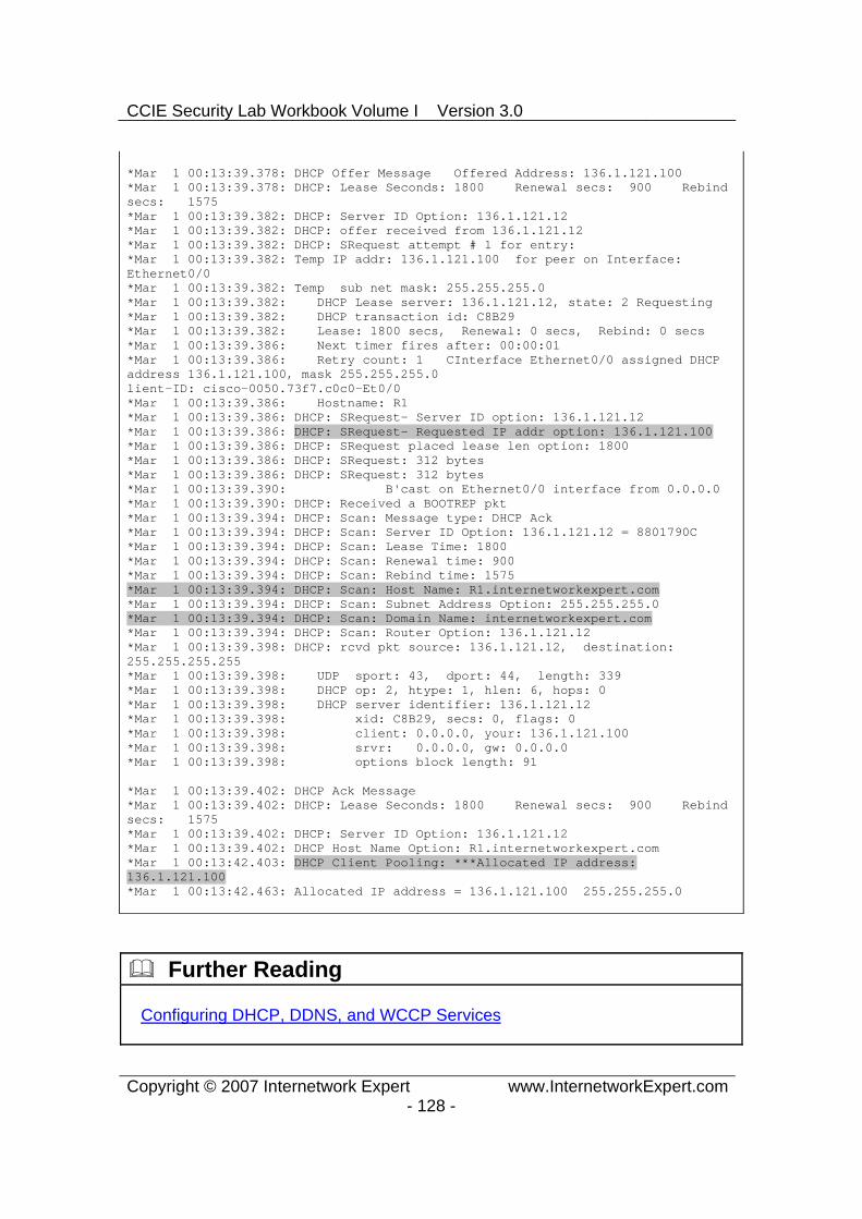
CCIE Security Lab Workbook Volume I Version 3.0
Copyright © 2007 Internetwork Expert www.InternetworkExpert.com- 128 -
*Mar 1 00:13:39.378: DHCP Offer Message Offered Address: 136.1.121.100 *Mar 1 00:13:39.378: DHCP: Lease Seconds: 1800 Renewal secs: 900 Rebind secs: 1575 *Mar 1 00:13:39.382: DHCP: Server ID Option: 136.1.121.12 *Mar 1 00:13:39.382: DHCP: offer received from 136.1.121.12 *Mar 1 00:13:39.382: DHCP: SRequest attempt # 1 for entry: *Mar 1 00:13:39.382: Temp IP addr: 136.1.121.100 for peer on Interface: Ethernet0/0*Mar 1 00:13:39.382: Temp sub net mask: 255.255.255.0 *Mar 1 00:13:39.382: DHCP Lease server: 136.1.121.12, state: 2 Requesting *Mar 1 00:13:39.382: DHCP transaction id: C8B29 *Mar 1 00:13:39.382: Lease: 1800 secs, Renewal: 0 secs, Rebind: 0 secs *Mar 1 00:13:39.386: Next timer fires after: 00:00:01 *Mar 1 00:13:39.386: Retry count: 1 CInterface Ethernet0/0 assigned DHCP address 136.1.121.100, mask 255.255.255.0 lient-ID: cisco-0050.73f7.c0c0-Et0/0 *Mar 1 00:13:39.386: Hostname: R1 *Mar 1 00:13:39.386: DHCP: SRequest- Server ID option: 136.1.121.12 *Mar 1 00:13:39.386: DHCP: SRequest- Requested IP addr option: 136.1.121.100 *Mar 1 00:13:39.386: DHCP: SRequest placed lease len option: 1800 *Mar 1 00:13:39.386: DHCP: SRequest: 312 bytes *Mar 1 00:13:39.386: DHCP: SRequest: 312 bytes *Mar 1 00:13:39.390: B'cast on Ethernet0/0 interface from 0.0.0.0 *Mar 1 00:13:39.390: DHCP: Received a BOOTREP pkt *Mar 1 00:13:39.394: DHCP: Scan: Message type: DHCP Ack *Mar 1 00:13:39.394: DHCP: Scan: Server ID Option: 136.1.121.12 = 8801790C *Mar 1 00:13:39.394: DHCP: Scan: Lease Time: 1800 *Mar 1 00:13:39.394: DHCP: Scan: Renewal time: 900 *Mar 1 00:13:39.394: DHCP: Scan: Rebind time: 1575 *Mar 1 00:13:39.394: DHCP: Scan: Host Name: R1.internetworkexpert.com *Mar 1 00:13:39.394: DHCP: Scan: Subnet Address Option: 255.255.255.0 *Mar 1 00:13:39.394: DHCP: Scan: Domain Name: internetworkexpert.com *Mar 1 00:13:39.394: DHCP: Scan: Router Option: 136.1.121.12 *Mar 1 00:13:39.398: DHCP: rcvd pkt source: 136.1.121.12, destination:255.255.255.255*Mar 1 00:13:39.398: UDP sport: 43, dport: 44, length: 339 *Mar 1 00:13:39.398: DHCP op: 2, htype: 1, hlen: 6, hops: 0 *Mar 1 00:13:39.398: DHCP server identifier: 136.1.121.12 *Mar 1 00:13:39.398: xid: C8B29, secs: 0, flags: 0 *Mar 1 00:13:39.398: client: 0.0.0.0, your: 136.1.121.100 *Mar 1 00:13:39.398: srvr: 0.0.0.0, gw: 0.0.0.0 *Mar 1 00:13:39.398: options block length: 91
*Mar 1 00:13:39.402: DHCP Ack Message *Mar 1 00:13:39.402: DHCP: Lease Seconds: 1800 Renewal secs: 900 Rebind secs: 1575 *Mar 1 00:13:39.402: DHCP: Server ID Option: 136.1.121.12 *Mar 1 00:13:39.402: DHCP Host Name Option: R1.internetworkexpert.com *Mar 1 00:13:42.403: DHCP Client Pooling: ***Allocated IP address: 136.1.121.100*Mar 1 00:13:42.463: Allocated IP address = 136.1.121.100 255.255.255.0
Further Reading
Configuring DHCP, DDNS, and WCCP Services

CCIE Security Lab Workbook Volume I Version 3.0
Copyright © 2007 Internetwork Expert www.InternetworkExpert.com- 129 -
Modular Policy Framework
HTTP Inspection with MPF
Objective: Configure different inspection policies for HTTP traffic on outside and inside interfaces.
Directions
Configure devices as per the scenario “PIX/ASA Firewall/Access Control” ”Common Configuration”.
MPF configuration is similar to MQC configuration on IOS router. You define the class map to match traffic using L3/L4 criterias and use the policy map to define corresponding action.
Unlike IOS, the firewall has additional types of class-maps and policy-maps to implement granular traffic-inspection policies.
Inspection class maps have certain types, and can be used to group classification criterias. Later, they can be configured inside the inspection policy-maps having the same type and associated with inspection policy.
For example, with FTP inspection policy-map. You may utilize class-maps that group together certain FTP commands or file types.

CCIE Security Lab Workbook Volume I Version 3.0
Copyright © 2007 Internetwork Expert www.InternetworkExpert.com- 130 -
The inspection policy-maps may be applied inside L3/L4 policy-maps as inspection rules for selected traffic.
The firewall also has a default traffic inspection policy, which is applied globally for all traffic passing over any interface.
Configure the ASA as follows: o Statically map the IP 10.0.0.100 to 136.1.122.100. o Classify HTTP traffic from inside and outside interfaces as follows:
Create class-map HTTP_FROM_INSIDE to match traffic from inside network to host 10.0.0.100 port 80.
Create class-map HTTP_FROM_OUTSIDE to match traffic from outside network to host 136.1.122.100 port 80.
Use access-lists names HTTP_FROM_INSIDE and HTTP_FROM_OUTSIDE for this tasks.
o Create and apply access-list OUTSIDE_IN to permit HTTP access to 136.1.122.100.
o Create policy-map for HTTP traffic inspection as follows:
Name it HTTP_INSPECT. Reset on protocol violations. Spoof server header with the “Apache/2.2.0 (Unix)”.
Create policy-map for outside interface, name it OUTSIDE. For the class HTTP_FROM_INSIDE configure the following:
o Apply the HTTP inspection with policy-map HTTP_INSPECT.o Limit number of embryonic connections to 100 and maximum
connections to 200.
Create policy-map for inside interface, name it INSIDE. For the class HTTP_FROM_OUTSIDE configure the following:
o Apply the HTTP inspection with policy-map HTTP_INSPECT.o Limit number of embryonic connections to 500 and maximum
connections to 100.
Apply the policy-maps to the respective interfaces.
Final Configuration
ASA1:!! Static mapping!static (dmz,outside) 136.1.122.100 10.0.0.100 netmask 255.255.255.255 !

CCIE Security Lab Workbook Volume I Version 3.0
Copyright © 2007 Internetwork Expert www.InternetworkExpert.com- 131 -
! Define Access-Lists!access-list OUTSIDE_IN permit tcp any host 136.1.122.100 eq www
access-list HTTP_FROM_INSIDE permit tcp 136.1.121.0 255.255.255.0 host 10.0.0.100 eq www
access-list HTTP_FROM_OUTSIDE permit tcp 136.1.122.0 255.255.255.0 host 136.1.122.100 eq www
!! Apply outside ACL!access-group OUTSIDE_IN in interface outside
!! Define class-maps!class-map HTTP_FROM_INSIDE match access-list HTTP_FROM_INSIDE
class-map HTTP_FROM_OUTSIDE match access-list HTTP_FROM_OUTSIDE
!! Define HTTP inspection policy!policy-map type inspect http HTTP_INSPECT parameters spoof-server "Apache/2.2.0 (Unix)" protocol-violation action reset
!! Create policy maps!policy-map OUTSIDE class HTTP_FROM_OUTSIDE inspect http HTTP_INSPECT set connection conn-max 100 embryonic-conn-max 50
policy-map INSIDE class HTTP_FROM_INSIDE inspect http HTTP_INSPECT set connection conn-max 200 embryonic-conn-max 100
!! Apply the policies!service-policy OUTSIDE interface outside service-policy INSIDE interface inside
Verification
R1#telnet 10.0.0.100 80Trying 10.0.0.100, 80 ... Open GET / HTTP/1.1
HTTP/1.1 400 Bad Request Server:Apache/2.2.0 (Unix) Date: Wed, 10 Jan 2007 11:58:13 GMT Connection: close

CCIE Security Lab Workbook Volume I Version 3.0
Copyright © 2007 Internetwork Expert www.InternetworkExpert.com- 132 -
Content-Length: 4009 Content-Type: text/html
<!DOCTYPE HTML PUBLIC "-//W3C//DTD HTML 3.2 Final//EN">
R2#telnet 136.1.122.100 80Trying 136.1.122.100, 80 ... Open GET / HTTP/1.1
HTTP/1.1 400 Bad Request Server:Apache/2.2.0 (Unix) Date: Wed, 10 Jan 2007 11:59:27 GMT Connection: close Content-Length: 4009 Content-Type: text/html
<!DOCTYPE HTML PUBLIC "-//W3C//DTD HTML 3.2 Final//EN">
Further Reading
Using Modular Policy FrameworkConfiguring Application Layer Protocol Inspection

CCIE Security Lab Workbook Volume I Version 3.0
Copyright © 2007 Internetwork Expert www.InternetworkExpert.com- 133 -
Advanced FTP Inspection
Objective: Configure advanced FTP inspection policy.
ASA1
R3
R4
AAA/CAServer
Inside Outside
DMZ
136.X.124.0/24 VLAN124
R3.3
.4
.100
136.X.123.0/24 VLAN123
10.0.0.0/24 VLAN120
.12 .12
.12
RIPv2
Directions
Configure devices as per the scenario “PIX/ASA Firewall/Access Control” ”Common Configuration”.
The overall goal is to limit permitted FTP commands and prevent certain files download.
PIX/ASA firewall use flexible inspection configuration via MPF, that permits very granular and configurable protocol inspection.
Create regexps to match filenames in MPF configuration as follows:
o REG_26XX to match “̂c26.*” o REG_36XX to match “̂c36.*” o REG_28XX to match “̂c28.*”
Create class-map type regexp DENIED_FILES as follows:
o Match regexps REG_26XX, REG_28XX and REG_36XX.
Create classmap type “inspect FTP” named DENIED_COMMANDS as follows:

CCIE Security Lab Workbook Volume I Version 3.0
Copyright © 2007 Internetwork Expert www.InternetworkExpert.com- 134 -
o match requestcommand “DELE”. o match requestcommand “SITE” . o match requestcommand “RMD”.
Create policymap type “inspect FTP” named FTP_INSPECT as follows:
o To add some obfuscation, configure parameters “maskbanner” and “masksystreply”.
o Match files with names in regex of class DENIED_FILES. Reset connection on these events.
o Match command with names in class DENIED_COMMANDS. Reset such connections.
Create L3/L4 class-map FTP and match TCP port 21. Create policy-map OUTSIDE and configure class FTP within. Inspect FTP
and apply FTP inspection policy FTP_INSPECT. Apply policy-map OUTSIDE to the outside interface. Finally, create static NAT mapping and configure access-list to permit FTP
traffic from outside.
Final Configuration
ASA1:!! Regexps!regex REG_26XX "^c26.*" regex REG_36XX "^c36.*" regex REG_28XX "^c28.*" !! Class-map to group regexps!class-map type regex match-any DENIED_FILES match regex REG_26XX match regex REG_28XX match regex REG_36XX !! Class-map to group together the denied commands!class-map type inspect ftp match-all DENIED_COMMANDS match request-command site dele rmd !! FTP inspection policy, not the obfuscation options!policy-map type inspect ftp FTP_INSPECT parameters mask-banner mask-syst-reply match filename regex class DENIED_FILES reset class DENIED_COMMANDS reset !! Class to match FTP port (L3/L4)!

CCIE Security Lab Workbook Volume I Version 3.0
Copyright © 2007 Internetwork Expert www.InternetworkExpert.com- 135 -
class-map FTP match port tcp eq 21 !! Policy map to apply to outside interface!policy-map OUTSIDE class FTP inspect ftp strict FTP_INSPECT !! Apply policy to outside interface!service-policy OUTSIDE interface outside !! Static Mapping to simplify routing!static (dmz,o) 136.1.122.100 10.0.0.100 !! Outside ACL to permit FTP traffic!access-list OUTSIDE_IN permit tcp any host 136.1.122.100 eq 21 access-group OUTSIDE_IN in interface outside
Verification
Test PC:

CCIE Security Lab Workbook Volume I Version 3.0
Copyright © 2007 Internetwork Expert www.InternetworkExpert.com- 136 -

CCIE Security Lab Workbook Volume I Version 3.0
Copyright © 2007 Internetwork Expert www.InternetworkExpert.com- 137 -
Further Reading
Using Modular Policy FrameworkConfiguring Application Layer Protocol Inspection

CCIE Security Lab Workbook Volume I Version 3.0
Copyright © 2007 Internetwork Expert www.InternetworkExpert.com- 138 -
Advanced ESMTP Inspection
Objective: Configure advanced options for ESMTP inspection.
ASA1
R3
R4
AAA/CAServer
Inside Outside
DMZ
136.X.124.0/24 VLAN124
R3.3
.4
.100
136.X.123.0/24 VLAN123
10.0.0.0/24 VLAN120
.12 .12
.12
RIPv2
Directions
Configure devices as per the scenario “PIX/ASA Firewall/Access Control” ”Common Configuration”.
Configure static mapping for DMZ server 10.0.0.100 to the outside IP 136.X.122.100.
Create and apply access-list to outside interface to permit connections from outside to DMZ server via SMTP.
Configure classification criterias as follows:
o Create access-list SMTP_SERVER to match TCP traffic to 136.X.122.100 port 25.
o Create L3 class-map SMTP_SERVER and match access-list SMTP_SERVER within.
o Create regexp SPAMMERS and match the string “(cable|dsl|dialup)”.
Configure inspection policy. Create policy-map SMTP_INSPECT of type “inspect emstp” as follows.
o Enable banner obfuscation parameter.

CCIE Security Lab Workbook Volume I Version 3.0
Copyright © 2007 Internetwork Expert www.InternetworkExpert.com- 139 -
o Configure relay-domain cisco.com and reset non-conforming connections.
o Reset the connection if the number of invalid recipients is greater than 3.
o Reset the connection if sender address match any in regexp SPAMMERS.
Create policy-map OUTSIDE as follows:
o For class SMTP_SERVER inspect ESMTP protocol with custom policy SMTP_INSPECT.
o Sec connection parameters:
Number of embryonic connections to 50. Number of maximum allowed connections to 100.
Apply policy-map to the outside interface.
Final Configuration
SW1:!! Static mapping and access-list to permit SMTP!static (dmz,o) 136.1.122.100 10.0.0.100 access-list OUTSIDE_IN permit tcp any host 136.1.122.100 eq 25 access-group OUTSIDE_IN in interface outside
!! Access-list and L3/4 class-map!access-list SMTP_SERVER permit tcp any host 136.1.122.100 eq 25 class-map SMTP_SERVER match access-list SMTP_SERVER
!! Regexps to catch possible spammers!regex SPAMMERS “(cable|dsl|dialup)”
!! SMTP Inspection Policy!policy-map type inspect esmtp SMTP_INSPECT parameters mask-banner mail-relay cisco.com action drop-connection exit match invalid-recipients count gt 3 reset match sender-address regex SPAMMERS reset
!
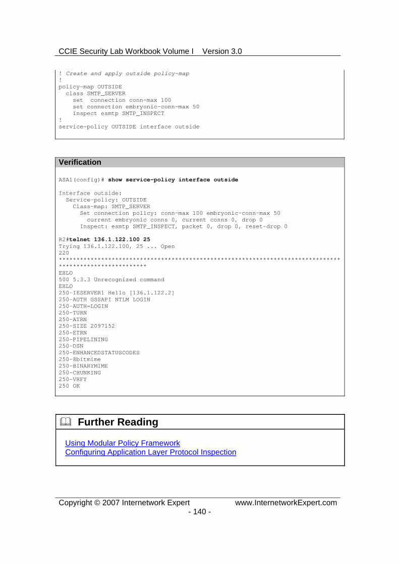
CCIE Security Lab Workbook Volume I Version 3.0
Copyright © 2007 Internetwork Expert www.InternetworkExpert.com- 140 -
! Create and apply outside policy-map!policy-map OUTSIDE class SMTP_SERVER set connection conn-max 100 set connection embryonic-conn-max 50 inspect esmtp SMTP_INSPECT !service-policy OUTSIDE interface outside
Verification
ASA1(config)# show service-policy interface outside
Interface outside: Service-policy: OUTSIDE Class-map: SMTP_SERVER Set connection policy: conn-max 100 embryonic-conn-max 50 current embryonic conns 0, current conns 0, drop 0 Inspect: esmtp SMTP_INSPECT, packet 0, drop 0, reset-drop 0
R2#telnet 136.1.122.100 25Trying 136.1.122.100, 25 ... Open 220*********************************************************************************************************EHLO500 5.3.3 Unrecognized command EHLO250-IESERVER1 Hello [136.1.122.2] 250-AUTH GSSAPI NTLM LOGIN 250-AUTH=LOGIN250-TURN250-ATRN250-SIZE 2097152 250-ETRN250-PIPELINING250-DSN250-ENHANCEDSTATUSCODES250-8bitmime250-BINARYMIME250-CHUNKING250-VRFY250 OK
Further Reading
Using Modular Policy FrameworkConfiguring Application Layer Protocol Inspection

CCIE Security Lab Workbook Volume I Version 3.0
Copyright © 2007 Internetwork Expert www.InternetworkExpert.com- 141 -
Authenticating BGP Session Through the Firewall
Objective: Configure authenticated BGP session through the firewall.
ASA1
R1
R2
AAA/CA Server
Inside Outside
DMZ
136.X.122.0/24 VLAN122
R3.1
.2
.100
136.X.121.0/24 VLAN121
10.0.0.0/24 VLAN120
.12 .12
.12
RIPv2
BGP AS 1
BGP AS 2
Directions
Configure devices as per the scenario “PIX/ASA Firewall/Access Control” ”Common Configuration”.
Configure BGP on R1 and R2 as per the diagram. Peer R1 and R2 using the ethernet interfaces IP addresses. Enable eBGP multihop for peering.
Authenticate BGP peering session using the password “CISCO”. In order to permit authenticated BGP session through the firewall, you
need to tune TCP protocol inspection, and permit TCP option 19 (which is used for authentication) as well as make sure that no TCP sequence number randomization is turned on for BGP connections.
Configure TCP map AUTH_OPTION and permit TCP option 19. Create L3/L4 class-map BGP, and match TCP port 179. Add class BGP to the default global_policy policy-map as follows:
o Disable TCP random sequencing o Apply TCP map AUTH_OPTION
Final Configuration
R1:router bgp 1 neighbor 136.1.122.2 remote-as 2 neighbor 136.1.122.2 ebgp neighbor 136.1.122.2 password CISCO
R2:

CCIE Security Lab Workbook Volume I Version 3.0
Copyright © 2007 Internetwork Expert www.InternetworkExpert.com- 142 -
router bgp 2 neighbor 136.1.121.1 remote-as 1 neighbor 136.1.121.1 ebgp neighbor 136.1.121.1 password CISCO
ASA1:!! TCP options!tcp-map AUTH_OPTION tcp-options range 19 19 allow !! Class to match BGP!class-map BGP match port tcp eq bgp !! Global policy config!policy-map global_policy class BGP set connection random-sequence-number disable set connection advanced-options AUTH_OPTION
Verification
R1#show ip bgp summary BGP router identifier 192.168.10.65, local AS number 1 BGP table version is 1, main routing table version 1
Neighbor V AS MsgRcvd MsgSent TblVer InQ OutQ Up/Down State/PfxRcd 136.1.122.2 4 2 5 6 1 0 0 00:00:23 0
ASA1(config-router)# show conn detail 6 in use, 18 most used Flags: A - awaiting inside ACK to SYN, a - awaiting outside ACK to SYN, B - initial SYN from outside, C - CTIQBE media, D - DNS, d - dump, E - outside back connection, F - outside FIN, f - inside FIN, G - group, g - MGCP, H - H.323, h - H.225.0, I - inbound data, i - incomplete, J - GTP, j - GTP data, K - GTP t3-response k - Skinny media, M - SMTP data, m - SIP media, O - outbound data, P - inside back connection, q - SQL*Net data, R - outside acknowledged FIN, R - UDP SUNRPC, r - inside acknowledged FIN, S - awaiting inside SYN, s - awaiting outside SYN, T - SIP, t - SIP transient, U - up X - inspected by service module TCP outside:136.1.122.2/179 inside:136.1.121.1/11019 flags UIO
Further Reading
Guide for Cisco PIX 6.2 and 6.3 Users Upgrading to Cisco Security Appliance Software Version 7.0
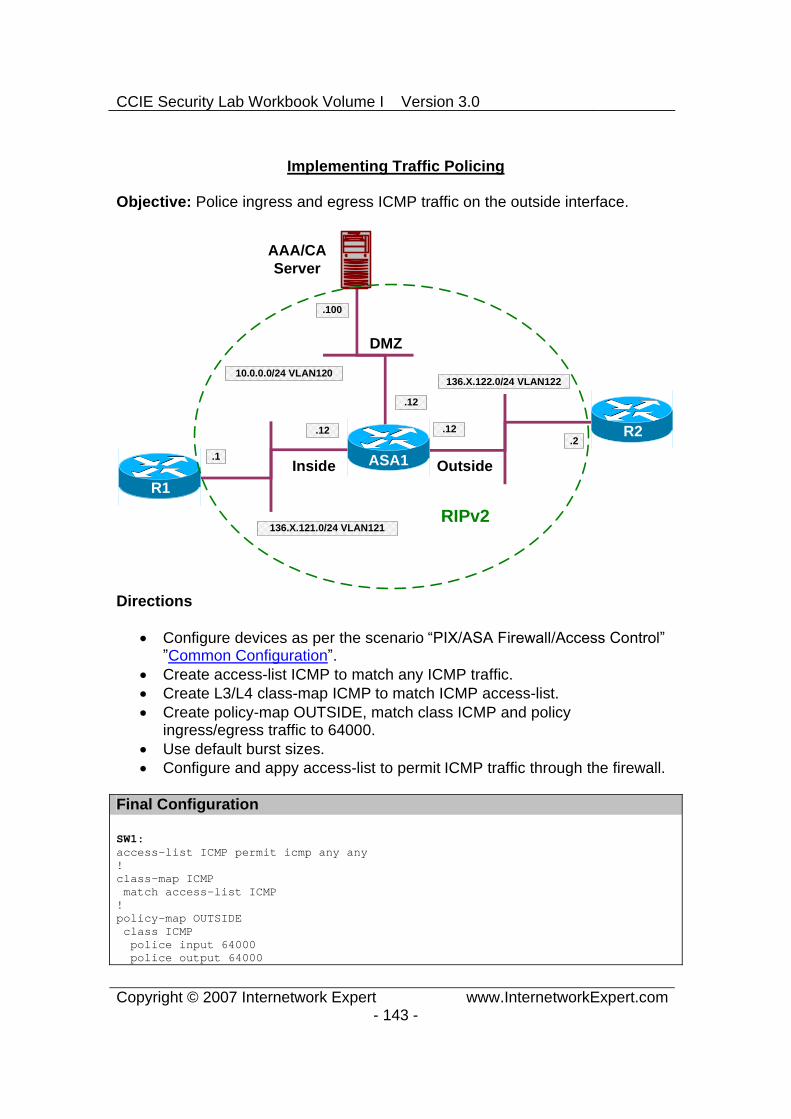
CCIE Security Lab Workbook Volume I Version 3.0
Copyright © 2007 Internetwork Expert www.InternetworkExpert.com- 143 -
Implementing Traffic Policing
Objective: Police ingress and egress ICMP traffic on the outside interface.
ASA1
R1
R2
AAA/CAServer
Inside Outside
DMZ
136.X.122.0/24 VLAN122
R3.1
.2
.100
136.X.121.0/24 VLAN121
10.0.0.0/24 VLAN120
.12 .12
.12
RIPv2
Directions
Configure devices as per the scenario “PIX/ASA Firewall/Access Control” ”Common Configuration”.
Create access-list ICMP to match any ICMP traffic. Create L3/L4 class-map ICMP to match ICMP access-list. Create policy-map OUTSIDE, match class ICMP and policy
ingress/egress traffic to 64000. Use default burst sizes. Configure and appy access-list to permit ICMP traffic through the firewall.
Final Configuration
SW1:access-list ICMP permit icmp any any !class-map ICMP match access-list ICMP !policy-map OUTSIDE class ICMP police input 64000 police output 64000

CCIE Security Lab Workbook Volume I Version 3.0
Copyright © 2007 Internetwork Expert www.InternetworkExpert.com- 144 -
!service-policy OUTSIDE interface outside !! Access-list to permit ICMP in/out!access-list OUTSIDE_IN permit icmp any any access-group OUTSIDE_IN in interface outside
Verification
R1#ping 136.1.122.2 size 1500 repeat 1000
Type escape sequence to abort. Sending 1000, 1500-byte ICMP Echos to 136.1.122.2, timeout is 2 seconds: !!!!!!.!!!!!!.!!!!!!.!!!!!!.!!!!!!.!!!!!.Success rate is 85 percent (35/41), round-trip min/avg/max = 8/9/24 ms
ASA1(config)# show service-policy interface outside
Interface outside: Service-policy: OUTSIDE Class-map: ICMP Input police Interface outside: cir 64000 bps, bc 2000 bytes conformed 0 packets, 0 bytes; actions: transmit exceeded 0 packets, 0 bytes; actions: drop conformed 0 bps, exceed 0 bps Output police Interface outside: cir 64000 bps, bc 2000 bytes conformed 45 packets, 62530 bytes; actions: transmit exceeded 5 packets, 7570 bytes; actions: drop conformed 24 bps, exceed 0 bps
Further Reading
Using Modular Policy FrameworkApplying QoS Policies

CCIE Security Lab Workbook Volume I Version 3.0
Copyright © 2007 Internetwork Expert www.InternetworkExpert.com- 145 -
Implementing Low Latency Queueing
Objective: Provide LLQ services for delay-sensitive traffic.
ASA1
R1
R2
AAA/CAServer
Inside Outside
DMZ
136.X.122.0/24 VLAN122
R3.1
.2
.100
136.X.121.0/24 VLAN121
10.0.0.0/24 VLAN120
.12 .12
.12
RIPv2
Directions
Configure devices as per the scenario “PIX/ASA Firewall/Access Control” ”Common Configuration”.
The goal is to provide LLQ services to voice packets from the outside. The first task is to classify voice traffic using the most appropriate method. Create class-map VOICE to match RTP protocol port range 16384 16383. Create policy-map LLQ and assign class VOICE to priority queue. Attach policy-map LLQ to inside interface (output interface). Tune priority-queue on inside interface to hold up to 5 packets max.
Final Configuration
ASA1:!! Class-map to match voice traffic!class-map VOICE match rtp 16384 16383 !! LLQ policy-map!policy-map LLQ class VOICE priority
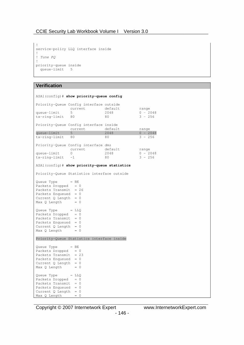
CCIE Security Lab Workbook Volume I Version 3.0
Copyright © 2007 Internetwork Expert www.InternetworkExpert.com- 146 -
!service-policy LLQ interface inside !! Tune PQ!priority-queue inside queue-limit 5
Verification
ASA1(config)# show priority-queue config
Priority-Queue Config interface outside current default range queue-limit 5 2048 0 - 2048 tx-ring-limit 80 80 3 - 256
Priority-Queue Config interface inside current default range queue-limit 5 2048 0 - 2048 tx-ring-limit 80 80 3 - 256
Priority-Queue Config interface dmz current default range queue-limit 0 2048 0 - 2048 tx-ring-limit -1 80 3 - 256
ASA1(config)# show priority-queue statistics
Priority-Queue Statistics interface outside
Queue Type = BE Packets Dropped = 0 Packets Transmit = 26 Packets Enqueued = 0 Current Q Length = 0 Max Q Length = 0
Queue Type = LLQ Packets Dropped = 0 Packets Transmit = 0 Packets Enqueued = 0 Current Q Length = 0 Max Q Length = 0
Priority-Queue Statistics interface inside
Queue Type = BE Packets Dropped = 0 Packets Transmit = 23 Packets Enqueued = 0 Current Q Length = 0 Max Q Length = 0
Queue Type = LLQ Packets Dropped = 0 Packets Transmit = 0 Packets Enqueued = 0 Current Q Length = 0 Max Q Length = 0

CCIE Security Lab Workbook Volume I Version 3.0
Copyright © 2007 Internetwork Expert www.InternetworkExpert.com- 147 -
Further Reading
Using Modular Policy FrameworkApplying QoS Policies

CCIE Security Lab Workbook Volume I Version 3.0
Copyright © 2007 Internetwork Expert www.InternetworkExpert.com- 148 -
TCP Normalization
Objective: Configure TCP normalization parameters for Telnet sessions.
ASA1
R1
R2
AAA/CAServer
Inside Outside
DMZ
136.X.122.0/24 VLAN122
R3.1
.2
.100
136.X.121.0/24 VLAN121
10.0.0.0/24 VLAN120
.12 .12
.12
RIPv2
Directions
Configure devices as per the scenario “PIX/ASA Firewall/Access Control” ”Common Configuration”.
TCP normalization permit the firewall to inspect and control certain TCP stream properties, as well as eliminate certain protocol anomalies.
Create L3/L4 class-map TELNET to match telnet traffic. Create TCP map named “TCP” as follows:
o Check retransmitted packets. o Verify TCP checksums. o Clear all reserverd bits in TCP headers.
Configure class TELNET within policymap “global_policy” and apply TCP map as advanced connection option.
Final Configuration
ASA1:tcp-map TCP check-retransmission checksum-verification reserved-bits clear
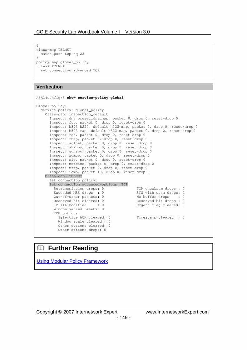
CCIE Security Lab Workbook Volume I Version 3.0
Copyright © 2007 Internetwork Expert www.InternetworkExpert.com- 149 -
!class-map TELNET match port tcp eq 23 !policy-map global_policy class TELNET set connection advanced TCP
Verification
ASA1(config)# show service-policy global
Global policy: Service-policy: global_policy Class-map: inspection_default Inspect: dns preset_dns_map, packet 0, drop 0, reset-drop 0 Inspect: ftp, packet 0, drop 0, reset-drop 0 Inspect: h323 h225 _default_h323_map, packet 0, drop 0, reset-drop 0 Inspect: h323 ras _default_h323_map, packet 0, drop 0, reset-drop 0 Inspect: rsh, packet 0, drop 0, reset-drop 0 Inspect: rtsp, packet 0, drop 0, reset-drop 0 Inspect: sqlnet, packet 0, drop 0, reset-drop 0 Inspect: skinny, packet 0, drop 0, reset-drop 0 Inspect: sunrpc, packet 0, drop 0, reset-drop 0 Inspect: xdmcp, packet 0, drop 0, reset-drop 0 Inspect: sip, packet 0, drop 0, reset-drop 0 Inspect: netbios, packet 0, drop 0, reset-drop 0 Inspect: tftp, packet 0, drop 0, reset-drop 0 Inspect: icmp, packet 10, drop 0, reset-drop 0 Class-map: TELNET Set connection policy: Set connection advanced-options: TCP Retransmission drops: 0 TCP checksum drops : 0 Exceeded MSS drops : 0 SYN with data drops: 0 Out-of-order packets: 0 No buffer drops : 0 Reserved bit cleared: 0 Reserved bit drops : 0 IP TTL modified : 0 Urgent flag cleared: 0 Window varied resets: 0 TCP-options: Selective ACK cleared: 0 Timestamp cleared : 0 Window scale cleared : 0 Other options cleared: 0 Other options drops: 0
Further Reading
Using Modular Policy Framework

CCIE Security Lab Workbook Volume I Version 3.0
Copyright © 2007 Internetwork Expert www.InternetworkExpert.com- 150 -
Management Traffic and MPF
Objective: Configure the firewall for inspection of RADIUS accounting packets.
ASA1
R1
R2
AAA/CAServer
Inside Outside
DMZ
136.X.122.0/24 VLAN122
R3.1
.2
.100
136.X.121.0/24 VLAN121
10.0.0.0/24 VLAN120
.12 .12
.12
RIPv2
Directions
Configure devices as per the scenario “PIX/ASA Firewall/Access Control” ”Common Configuration”.
Configure AAA RADIUS server on DMZ interface with IP 10.0.0.100 and key CISCO.
Create class-map named RADIUS of type management and match UDP port range 1645 1646.
Create policy-map INSPECT_RADIUS of type “inspect radiusaccounting”. Apply the following parameters:
o Validate attribute number 26. o Configure host 10.0.0.100 with key CISCO. o Send Accounting Response.
Assign class RADIUS to global_policy and apply RADIUS accounting inspection with policy-map INSPECT_RADIUS.

CCIE Security Lab Workbook Volume I Version 3.0
Copyright © 2007 Internetwork Expert www.InternetworkExpert.com- 151 -
Final Configuration
ASA1:!! Configure AAA server!aaa-server RADIUS protocol radius aaa-server RADIUS (dmz) host 10.0.0.100 CISCO !! Configure management class-map to match RADIUS ACC packets!class-map type management RADIUS match port udp eqradius-acct !! RADIUS inspection policy!policy-map type inspect radius-accounting RADIUS_INSPECT parameters send response validate-attribute 26 host 10.0.0.100 key CISCO !policy-map global_policy class RADIUS inspect radius-accounting RADIUS_INSPECT
Verification
ASA1(config)# show service-policy global
Global policy: Service-policy: global_policy Class-map: inspection_default Inspect: dns preset_dns_map, packet 0, drop 0, reset-drop 0 Inspect: ftp, packet 0, drop 0, reset-drop 0 Inspect: h323 h225 _default_h323_map, packet 0, drop 0, reset-drop 0 Inspect: h323 ras _default_h323_map, packet 0, drop 0, reset-drop 0 Inspect: rsh, packet 0, drop 0, reset-drop 0 Inspect: rtsp, packet 0, drop 0, reset-drop 0 Inspect: esmtp _default_esmtp_map, packet 0, drop 0, reset-drop 0 Inspect: sqlnet, packet 0, drop 0, reset-drop 0 Inspect: skinny, packet 0, drop 0, reset-drop 0 Inspect: sunrpc, packet 0, drop 0, reset-drop 0 Inspect: xdmcp, packet 0, drop 0, reset-drop 0 Inspect: sip, packet 0, drop 0, reset-drop 0 Inspect: netbios, packet 0, drop 0, reset-drop 0 Inspect: tftp, packet 0, drop 0, reset-drop 0 Class-map: RADIUS Inspect: radius-accounting RADIUS_INSPECT, packet 0
Further Reading
RADIUS Accounting Inspection

CCIE Security Lab Workbook Volume I Version 3.0
Copyright © 2007 Internetwork Expert www.InternetworkExpert.com- 152 -
ICMP Inspection Engine
Objective: Configure the firewall for ICMP traffic inspection with NAT.
ASA1
R1
R2
AAA/CA Server
Inside Outside
DMZ
136.X.122.0/24 VLAN122
R3.1
.2
.100
136.X.121.0/24 VLAN121
10.0.0.0/24 VLAN120
.12 .12
.12
RIPv2
Lo0: 150.X.1.1/24
Directions
Configure devices as per the scenario “PIX/ASA Firewall/Access Control” ”Common Configuration”.
Configure static NAT translation 136.X.121.1 to 136.X.122.1. Create Loopback0 interface on R1 and advertise it into RIP. Create access-list OUTSIDE_IN and permit inbound UDP packets. Apply
this access-list to the outside interface. Perform a traceroute to 150.1.1.1, note the responding IP address. Within “global_policy” and class “inspection_default” enable ICMP
inspection along with ICMP errors. Perform a traceroute to 150.1.1.1, and see how responding address has
changed. Additionally, ICMP inspection permits pings across the firewall, without
explicit ACL configuration on the outside interface.
Final Configuration
ASA1:
!! Static mapping!static (inside,outside) 136.1.122.1 136.1.121.1
!

CCIE Security Lab Workbook Volume I Version 3.0
Copyright © 2007 Internetwork Expert www.InternetworkExpert.com- 153 -
! Access-list to permit inboud traceroute !access-list OUTSIDE_IN permit udp any any access-group OUTSIDE_IN in interface outside
!! Apply ICMP inspection!policy-map global_policy class inspection_default inspect icmp error inspect icmp
Verification
Before the inspection was enabled:
R1#ping 136.1.122.2
Type escape sequence to abort. Sending 5, 100-byte ICMP Echos to 136.1.122.2, timeout is 2 seconds: .....Success rate is 0 percent (0/5) R1#
R2#traceroute 150.1.1.1
Type escape sequence to abort. Tracing the route to 150.1.1.1
1 136.1.121.1 4 msec * 0 msec
After:
R1#ping 136.1.122.2
Type escape sequence to abort. Sending 5, 100-byte ICMP Echos to 136.1.122.2, timeout is 2 seconds: !!!!!Success rate is 100 percent (5/5), round-trip min/avg/max = 100/158/176 ms R1#
R2#traceroute 150.1.1.1
Type escape sequence to abort. Tracing the route to 150.1.1.1
1 136.1.122.1 4 msec * 0 msec
Further Reading
ICMP Inspection