CC130338 Flight Safety Investigation Report
47
1010-CC130-172304 (DFS 2-7) 24 January 2018 CC130338 Flight Safety Investigation Report
Transcript of CC130338 Flight Safety Investigation Report

1010-CC130-172304 (DFS 2-7)
24 January 2018
CC130338
Flight Safety Investigation Report

INTENTIONALLY LEFT BLANK

Flight Safety Investigation Report – CC130338 –8 Mar 2017
CANADIAN ARMED FORCES FLIGHT SAFETY INVESTIGATION REPORT (FSIR)
Final Report
FILE NUMBER: 1010-CC130-172304 (DFS 2-7)
FSIMS OCCURRENCE NUMBER: 172304
DATE OF REPORT: 24 January 2018
OCCURRENCE CATEGORY: "A"
AIRCRAFT TYPE: CC130 Hercules
AIRCRAFT TAIL NUMBER CC130338
DATE OF OCCURRENCE: 8 March 2017
TIME OF OCCURRENCE (L): 1346 Central Standard Time
LOCATION: 0.5 kilometers north of the Yorkton Airport, Saskatchewan
N 51˚ 16.34’ / W102˚ 27.58’
This report was produced under authority of the Minister of National Defence (MND) pursuant to section 4.2 (1)(n) and 4.2 (2) of the Aeronautics Act, and in accordance with the A-GA-135-
001/AA-001, Flight Safety for the Canadian Armed Forces.
The contents of this report shall only be used for the sole purpose of accident prevention. This report was released under the authority of the Director of Flight Safety (DFS), National Defence
Headquarters, pursuant to powers delegated to him by the MND as the Airworthiness Investigative Authority (AIA) for the Canadian Armed Forces under Part II, section 12 of the
Aeronautics Act.

Flight Safety Investigation Report – CC130338 –8 Mar 2017
SYNOPSIS
The accident occurred during a 435 (Transport and Rescue) Squadron CC130H Hercules Search and Rescue training mission. The aircraft departed Winnipeg with a crew of nine and proceeded to the Pelly / Kamsak area of Saskatchewan to complete basic Search and Rescue sequences and then transited to the Yorkton airport with the intent of doing live static line parachute jumps followed by supply drops.
Once in the Yorkton area the aircraft was established at 2,000 feet above ground in level flight at 124 knots indicated airspeed in a flap 50 percent configuration and flown into wind over the desired target. The sky was clear, it was -16o
Celsius and the surface wind was out of the northwest at 19 knots gusting to 24 knots. After completing their briefings and safety checks, the Search and Rescue Technician Team Leader exited the aircraft via the open rear ramp at the pre-determined point. The Team Leader exited using the “ball” style technique. The Search and Rescue Technician Team Member followed a few seconds after the Team Leader using the “reverse arch” (semi-sitting) exit technique.
Immediately after leaving the aircraft the Team Member appeared to interact with the aircraft’s slipstream, causing his left leg to move upwards and his body to roll slightly to the right. As this was happening, the static parachute line system began to deploy his main parachute. The parachute did not deploy normally and the evidence strongly suggests that the main canopy suspension lines became severely twisted. This resulted in an uncontrollable parachute that entered a rapidly descending clockwise spiral.
The Team Member was observed to attempt to untwist the lines, and at one point performed the non-standard action of releasing his Search and Rescue – Personnel Equipment Lowering System bag, presumably to aid in the required kicking motion with his legs. His efforts were unsuccessful and while attempting to clear the twists he likely lost situational awareness of his altitude and descent rate. As a result, he did not take action to cut-away and deploy his reserve parachute before reaching the ground.
The team member was fatally injured when he struck the ground.
The investigation did not find any evidence of an improper pack or a materiel failure of the Team Member’s equipment. Malfunctions during parachute jumps from the lower altitudes (for example 1,500 to 2,000 ft above ground) leave little time and action must be taken quickly to resolve the problem or cut-away the main parachute and deploy the reserve.
Preventive measures are focussed on enhanced training processes and the implementation of an automatic altitude awareness aural warning device.
Flight Safety Investigation Report – CC130338 –8 Mar 2017
i
TABLE OF CONTENTS
1. FACTUAL INFORMATION .................................................................... 1
1.1. HISTORY OF THE FLIGHT ........................................................................... 1
1.2. INJURY TO PERSONNEL ............................................................................. 4
1.3. DAMAGE TO PARACHUTE........................................................................... 4
1.4. COLLATERAL DAMAGE .............................................................................. 5
1.5. PERSONNEL INFORMATION ........................................................................ 5
1.6. CSAR 7(A) PARACHUTE INFORMATION ...................................................... 6
1.7. METEOROLOGICAL INFORMATION ............................................................. 15
1.8. AIDS TO NAVIGATION .............................................................................. 15
1.9. COMMUNICATIONS .................................................................................. 15
1.10. AERODROME INFORMATION ..................................................................... 15
1.11. FLIGHT RECORDERS ............................................................................... 16
1.12. WRECKAGE AND IMPACT INFORMATION .................................................... 16
1.13. MEDICAL ................................................................................................ 16
1.14. FIRE, EXPLOSIVES DEVICES, AND MUNITIONS ........................................... 16
1.15. SURVIVAL ASPECTS ................................................................................ 17
1.16. TEST AND RESEARCH ACTIVITIES ............................................................. 18
1.17. ORGANIZATIONAL AND MANAGEMENT INFORMATION .................................. 19
1.18. ADDITIONAL INFORMATION ...................................................................... 20
1.19. USEFUL OR EFFECTIVE INVESTIGATION TECHNIQUES ................................. 26
2. ANALYSIS ........................................................................................... 27
2.1. GENERAL ............................................................................................... 27
2.2. PARACHUTE DEPLOYMENT ...................................................................... 27
2.3. PARACHUTE MALFUNCTION ..................................................................... 28
2.4. EMERGENCY PROCEDURES ..................................................................... 29
2.5. ARMING OF THE CYPRES 2 AAD .............................................................. 30
2.6. MINIMUM JUMP ALTITUDES ....................................................................... 30
3. CONCLUSIONS .................................................................................. 32
3.1. FINDINGS ............................................................................................... 32
3.2. CAUSE FACTORS .................................................................................... 34
4. PREVENTIVE MEASURES ................................................................. 35
4.1. PREVENTIVE MEASURES TAKEN .............................................................. 35

Flight Safety Investigation Report – CC130338 –8 Mar 2017
ii
4.2. PREVENTIVE MEASURES RECOMMENDED ................................................. 36
4.3. OTHER SAFETY MEASURES RECOMMENDED ............................................. 36
4.4. AIRWORTHINESS INVESTIGATIVE AUTHORITY REMARKS ............................. 37
ANNEXES
ANNEX A - Abbreviations ................................................................................. A-1
ANNEX B – Figures and Tables ....................................................................... B-1

Flight Safety Investigation Report – CC130338 –8 Mar 2017
1/37
1. FACTUAL INFORMATION
1.1. HISTORY OF THE FLIGHT
1.1.1. The occurrence involved the 435 (Transport and Rescue) (T & R) Squadron duty search and rescue (SAR) crew and aircraft CC130338, a SAR configured CC130H Hercules. The crew briefed at 0815 local (L) Central Standard Time (CST) on the day of the occurrence and, after reviewing the weather, generated a plan to conduct crew training in the area of Yorkton, Saskatchewan. The SAR crew comprised two Pilots (aircraft commander and first officer), two Air Combat Systems Officers (ACSOs) (one instructor and one under training), two Flight Engineers (one operational and one undergoing evaluation), a loadmaster (LM) and two SAR Technicians (SAR Techs): a Team Lead (TL) and a Team Member (TM).
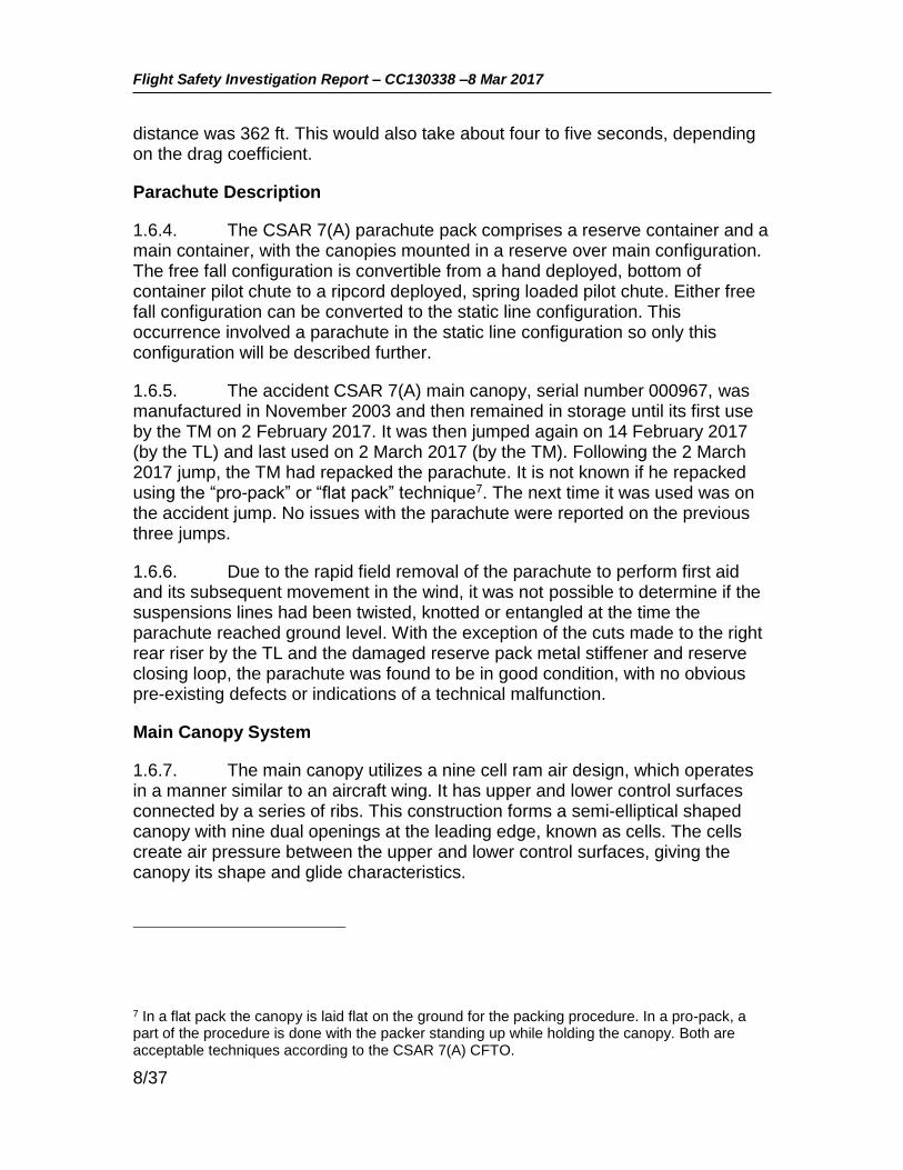
1.1.2. The flight departed Winnipeg at 1100 L and following initial training in the Pelly and Kamsak area, the crew transited to the Yorkton airport (CYQV) for the next training sequence, which was to be a SAR Tech parachute insertion followed by a bundle drop (comprising various equipment required by the SAR Techs on the ground). Enroute to Yorkton the pilots obtained updated weather information from the local automated weather observation station (AWOS). The surface winds were determined to be within the parachute training limit of 25 knots. An area adjacent to the threshold of CYQV Runway 21 (see Figure 1) was picked as the drop zone for the exercise. The TL and TM carried out each other’s safety checks, observed by the LM, and a crew briefing for the drop was completed. Streamers were dropped to determine the exit point for an into-wind jump pattern. All checks were done in accordance with the Standard Manoeuvre

Flight Safety Investigation Report – CC130338 –8 Mar 2017
2/37
Manual (SMM)1. As part of their normal duties, the LM and both ACSOs were in the aft fuselage/ramp area to assist the SAR Techs.
Figure 1: Accident Area Map (Base map from Google Maps)
1.1.3. For the drop the aircraft was flown at an altitude of 2,000 feet above ground level (AGL) at 124 knots indicated airspeed (KIAS) with the flaps set at 50 percent (i.e., the normal CC130H configuration and speed for a live parachute drop). Upon reaching the desired drop point, the TL exited first and without incident using the “ball” position. The TM followed two to three seconds later. Facing aft, (towards the open ramp from inside the fuselage), and using the “reverse arch” position, a semi-seated posture with arms extended, he departed from a position on the ramp centreline or possibly very slightly right of the centreline. No abnormalities with the initial departure or static line deployment were observed but once clear of the ramp, the TM’s body was observed to move
1 Air Mobility Standard Manoeuvre Manual – CC130 E/H Search and Rescue Operations – Change 1 dated 1 July 2014
NORTH
CYQV
Runway 21
Accident Site
CC130H Flight Path

Flight Safety Investigation Report – CC130338 –8 Mar 2017
3/37
into a more supine position, with his right shoulder pivoting down and to the right and his left leg moving upwards.
1.1.4. The static line was observed to pay out cleanly, the parachute pack opened and the parachute began to billow; however, it never fully developed. The left side of the parachute canopy appeared to open normally but the right side, as seen from the aircraft ramp looking aft, did not, and appeared lower than the left side. The parachute immediately began to turn to the right and quickly developed into a rapidly descending right-hand (clockwise) spiral.
1.1.5. While carrying out his own post-deployment procedures (PDP), the TL observed the TM in a tight right spiral descent with his Search and Rescue – Personnel Equipment Lowering System (SAR-PELS) deployed. The TM was observed to manipulate the risers with both hands, bring his hands down to his chest area, return to the risers and lastly bringing hands back down to the chest area before striking the ground in a horizontal or near horizontal position. The entire descent took approximately 37 seconds.
1.1.6. When the pilots did not immediately receive the expected “two good chutes, clear to manoeuvre” call from the LM, the flying pilot queried the LM to which the LM and ACSO instructor both replied that the TM did not have a good exit and that he was in a spiral heading straight down. They then informed the crew that the TM had hit the ground hard. The aircraft captain immediately transmitted a request, via Regina Radio (the flight service station), for emergency services.
1.1.7. Concurrently, the TL manoeuvred his parachute to land as close to the TM as he could, quickly discarded his parachute and then ran to the TM, finding him unresponsive. To provide better access to the TM to perform cardiopulmonary resuscitation (CPR), the TL attempted to release the TM from his parachute by pulling the parachute cut-away pillow, which was found immediately adjacent to its normal stowage location (see Figure 4), and then used the TM’s hook knife to cut the reserve static line (RSL) on the right riser. Once free of the TM, the parachute was then blown by the wind a short distance downwind (see Figure 2). The TM remained unresponsive and the TL continued to perform CPR until further assistance arrived and the TM was pronounced deceased by an Emergency Medical Services (EMS) paramedic.

Flight Safety Investigation Report – CC130338 –8 Mar 2017
4/37
Figure 2: TM Canopy and Harness in situ, looking southeast.
1.1.8. The aircraft commander made the decision to land immediately at the Yorkton airport with the intention of providing any required equipment or assistance by foot. After landing, the aircraft was taxied to and parked at the threshold of Runway 21, which was as close to the accident site as they could get. However, it was quickly realised that the distance to the accident site was too far and had too many obstacles to enable a timely arrival by foot. Unable to provide further support, the aircraft was eventually taxied back to the main ramp and shutdown.
1.2. INJURY TO PERSONNEL
1.2.1. The SAR Tech TM was fatally injured.
1.3. DAMAGE TO PARACHUTE
1.3.1. The parachute was examined in detail by the Canadian Armed Forces (CAF) Senior Parachute Rigger, his staff, and specialists from the Escape Systems section of the Aerospace Engineering Test Establishment. The right rear riser had a significant cut, caused when the TL used the hook knife to cut the RSL in an attempt to release the TM from his parachute to perform first aid.

Flight Safety Investigation Report – CC130338 –8 Mar 2017
5/37
There was a dark brown mark noted on one of the left side suspension lines but the suspension line itself was in good condition. The reserve pack metal stiffener was slightly bent and the reserve closing loop was found snapped apart. There was no other apparent damage to the harness, the suspension lines, the canopy, or the associated hardware. Specifically, there was no evidence (marks, material transfer or other damage) to indicate that a line had become trapped over top of the canopy (known as a “line over”).
1.4. COLLATERAL DAMAGE
Nil
1.5. PERSONNEL INFORMATION
1.5.1. All crew members were qualified and current for the mission. Detailed information for the TL and TM is provided in Table 1.
SAR Tech TL SAR Tech TM
Medical Category Date 26 Aug 16 14 Sep 16
SAR Tech Category expiry date* 28 Aug 17 28 Feb 19
Fixed Wing Parachuting currencies ** Current Current
No. of Static Line Jumps @ 1500’ AGL 5 1
No. of Static Line Jumps @ 2000’ AGL 29 5
Total Static Line Jumps 159 71
Jumps Last 30 Days 34 7
Grand Total Jumps 402 161
Table 1. Personnel Information
* Basic category- Valid for 2 years. ** Quarterly 3 live parachute descents (2 Static / 1 freefall), 2 SAR-PELS jumps ** Semi-annually: Parachute emergencies training to include static line, free fall,
unconventional landing situations and tree let down and a review of the Canadian Forces School of SAR Parachute Training Precis, 1 confined area jump wearing the Bush Suit, SAR-PELS and tree let down device.
** Annually: 1 night jump and 1 open water live jump.
SAR Tech Team Leader
1.5.2. The TL was an experienced SAR Tech, with over seven years operational experience in the role, and had previously served as a TL at several other SAR squadrons before serving at 435 (T&R) Squadron. In addition to being a TL at 435 (T&R) Squadron, he was also the Squadron’s SAR Tech Training

Flight Safety Investigation Report – CC130338 –8 Mar 2017
6/37
Coordinator, in which he coordinated and provided training to the other SAR Techs on Squadron.
SAR Tech Team Member
1.5.3. The TM attended Canadian Forces School of Search and Rescue from July 2015 to June 2016 and graduated with a Restricted Team Member Category. The TM had no parachuting experience prior to attending the SAR Tech course. In July 2016 he was posted to 435 (T&R) Squadron as a SAR Tech and began training to achieve the Operational Team Member Category. An extension to the normal four month upgrade timeline was sought, and approved, to overcome some difficulty he was having with the accuracy of his parachute landings. Additional parachute training was completed and on 9 February 2017 he successfully completed a SAR Tech proficiency check, which included live static parachute jumps with equipment. His performance on the static line jumps exceeded the minimum performance level required. Effective 28 February 2017 the TM was granted an Operational Team Member Category by the Squadron’s Commanding Officer. His last jump prior to the accident, and the last time the occurrence parachute had been used, was a static line jump in Comox, British Columbia on 2 March 2017.
1.5.4. SAR Techs are trained and qualified to repack the main canopy following a jump (the reserve parachutes are always repacked by parachute riggers). The TM had repacked the occurrence parachute on 2 March 2017. The TM had a reputation as a meticulous and careful packer.
1.5.5. The TM had completed the required semi-annual parachute emergency training on 6 March 2017, just two days prior to the accident. It is unknown how many, if any, actual parachute malfunctions the TM had experienced prior to the accident jump.
1.6. CSAR 7(A) PARACHUTE INFORMATION
1.6.1. The aircraft was examined and found to have been configured properly. The static line system and all other aircraft systems functioned normally and will not be discussed further in this report. This section will describe the Canadian Search and Rescue (CSAR) 7(A) parachute system and the SAR-PELS.
Operational Test and Evaluation (OT&E)
1.6.2. The CSAR 7 parachute is a variant of the Sun Path Javelin container/harness with the Military Silhouette MS-300 series main canopy and
Flight Safety Investigation Report – CC130338 –8 Mar 2017
7/37
the Tactical Reserve 335. Operational testing and evaluation (OT&E)2 was completed in 2001/2002 and the parachute was introduced into service in 2003, replacing the CSAR 4 parachute. As part of the OT&E process, static line jumps were conducted with the SAR-PELS and from as low as 1,200 ft AGL. It received its CC130 Hercules technical airworthiness clearance (TAC) in February 2003 and its initial CC130 operational airworthiness clearance (OAC) in August 2003. The CSAR 7 parachute was later equipped with the “skyhook” modification (see para 1.6.19) and became the CSAR 7(A) variant. Its latest OAC3 was approved in October 2014. The OAC stated the minimum approved altitude was 1,200 ft AGL for operational static jumps and 1,500 ft AGL for training static jumps, unchanged from the original TAC/OAC. It also stated that use of the Military Cybernetic Parachute Release (CYPRES) 2 automatic activation device (AAD) was at the individual SAR Tech’s discretion for jumps at 2,000 ft AGL and above. If used in accordance with the original equipment manufacturer’s instructions and CAF issued direction, the risk of using this parachute and the associated equipment, was determined to be at the acceptable level of safety. The OAC also included approval for use of the CSAR 7(A) with the version of SAR-PELS that was in use at the time. Technical and operational airworthiness clearances for use of the CSAR 7(A) with the new SAR-PELS and with the CC130H were issued on 21 January 2014 and 21 July 2014 respectively4,5.
1.6.3. The manufacturer’s technical specifications for the MS-300 series main canopy state that the minimum static deployment altitude is 2,000 ft AGL. The Canadian Forces Technical Order (CFTO)6 for the CSAR 7(A) also states that the minimum static deployment altitude is 2,000 ft. AGL and that the opening distance (height lost during the deployment sequence) in static line mode is 210 ft. This is a minimum value and the altitude loss can be greater, depending on how the parachute is packed and the desired degree of opening shock. During the OT&E it was found that at an exit speed of 130 KIAS the average opening
2 ATES 10081 -01/01 CSAR 7 Project Report -Replacement SAR Parachute OT&E Evaluation SUN PATH Military Javelin 2 July 02
3 3385-23 (SO SAR Sys) 27 October 2014 – OPERATIONAL AIRWORTHINESS CLEARANCE (OAC) – SEARCH AND RESCUE (SAR) PARACHUTES – Revision 1
4 11670-01 (DAEPMFT 6-3-3) 21 January 2014 TECHNICAL AIRWORTHINESS CLEARANCE (TAC) FREE FALL SEARCH AND RESCUE – PERSONAL EQUIPMENT LOWERING SYSTEM (FF SAR-PELS)
5 MESSAGE – COMD 1117 – 211624Z JUL 14 – OAC – FF SAR PELS FOR USE ON CC115, CC130H, CH146, AND CC130J.
6Manual C-22-622-000/MF-001 - CSAR 7(A) PARACHUTE ASSEMBLY- 2010-12-09
Flight Safety Investigation Report – CC130338 –8 Mar 2017
8/37
distance was 362 ft. This would also take about four to five seconds, depending on the drag coefficient.
Parachute Description
1.6.4. The CSAR 7(A) parachute pack comprises a reserve container and a main container, with the canopies mounted in a reserve over main configuration. The free fall configuration is convertible from a hand deployed, bottom of container pilot chute to a ripcord deployed, spring loaded pilot chute. Either free fall configuration can be converted to the static line configuration. This occurrence involved a parachute in the static line configuration so only this configuration will be described further.
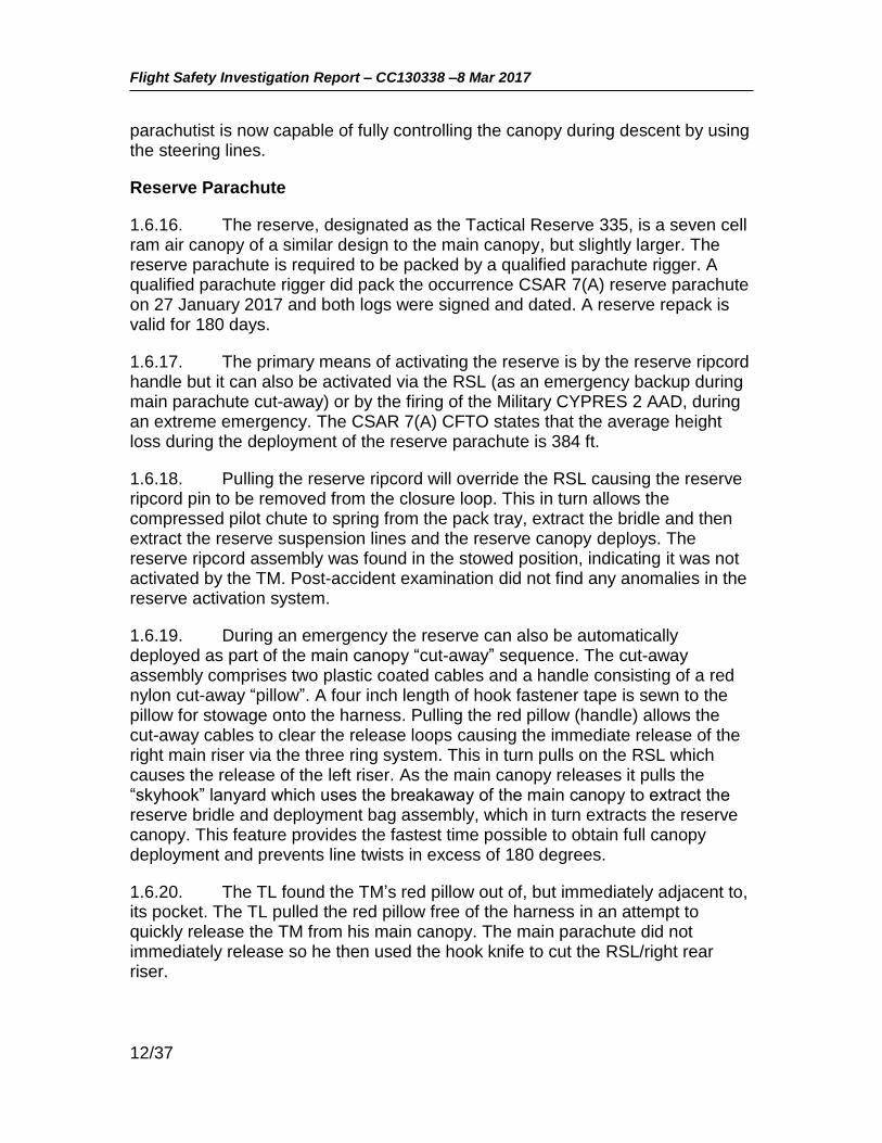
1.6.5. The accident CSAR 7(A) main canopy, serial number 000967, was manufactured in November 2003 and then remained in storage until its first use by the TM on 2 February 2017. It was then jumped again on 14 February 2017 (by the TL) and last used on 2 March 2017 (by the TM). Following the 2 March 2017 jump, the TM had repacked the parachute. It is not known if he repacked using the “pro-pack” or “flat pack” technique7. The next time it was used was on the accident jump. No issues with the parachute were reported on the previous three jumps.
1.6.6. Due to the rapid field removal of the parachute to perform first aid and its subsequent movement in the wind, it was not possible to determine if the suspensions lines had been twisted, knotted or entangled at the time the parachute reached ground level. With the exception of the cuts made to the right rear riser by the TL and the damaged reserve pack metal stiffener and reserve closing loop, the parachute was found to be in good condition, with no obvious pre-existing defects or indications of a technical malfunction.
Main Canopy System
1.6.7. The main canopy utilizes a nine cell ram air design, which operates in a manner similar to an aircraft wing. It has upper and lower control surfaces connected by a series of ribs. This construction forms a semi-elliptical shaped canopy with nine dual openings at the leading edge, known as cells. The cells create air pressure between the upper and lower control surfaces, giving the canopy its shape and glide characteristics.
7 In a flat pack the canopy is laid flat on the ground for the packing procedure. In a pro-pack, a part of the procedure is done with the packer standing up while holding the canopy. Both are acceptable techniques according to the CSAR 7(A) CFTO.

Flight Safety Investigation Report – CC130338 –8 Mar 2017
9/37
Figure 3: CSAR 7(A) Main Canopy Schematic
1.6.8. The canopy is certified for a maximum suspended load of 375 pounds. The main canopy (see Figure 3) is connected to the risers via four braided polyester suspension line groups, each with five suspension lines. The suspension lines distribute a suspended load under the canopy without distorting the canopy’s airfoil shape. Upper control lines converge from points of attachment on the left and right trailing edges of the tail, respectively, to common connection points with the lower control lines. The lines attached to the trailing edge are the steering lines which in turn are connected to a left and right steering toggles.
1.6.9. A rectangular slider, comprised of rip-stop nylon with a large grommet in each corner, is a device that by design slows the opening of the parachute. Groups of suspension lines pass through the applicable corner grommet and the applicable left or right steering toggle line also passes through
Front
Back

Flight Safety Investigation Report – CC130338 –8 Mar 2017
10/37
the applicable (left or right) rear grommets. Below the slider, each group of suspension lines are connected to their respective riser via a stainless steel barrel nut style rapide link. The slider was found to be in excellent condition, relatively new with no apparent damage. All the grommets were in excellent condition. There were no burrs noted that could cause the lines to snag or would have prevented proper movement up or down the suspension lines.
1.6.10. The main riser assembly is made from nylon webbing. The bottom end of each riser incorporates two rings of the three ring release system8, a grommet and a locking loop. A channel is sewn to the back of the rear riser strap for stowage of the main cut-away ripcord cable. The back of the rear riser also incorporates steering line keepers for stowage of excess steering line, and steering line toggle keepers for stowage of steering line toggles. The control lines on the occurrence parachute were noted to be relatively new, in excellent condition, and with no apparent damage. They were routed correctly through the proper slider grommets and the guide rings on the risers. The steering toggles were stowed at the 50% packed position, indicating they were never utilized during the jump. An RSL connector quick release is attached to the right hand riser.
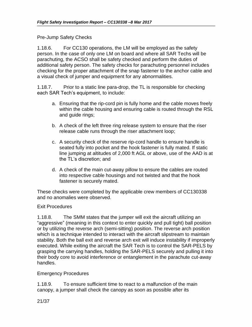
1.6.11. The harness (see Figure 4) is made of wide nylon webbing and is an integral part of the pack. The harness incorporates hardware for the three ring canopy release, D rings and webbing loops for equipment and carrying pockets, and housings for the main, reserve and cut-away ripcords.
8 The three-ring release system allows a malfunctioning main parachute to be cut-away with a single motion. A large bottom ring is securely attached to the skydiver's harness, the middle ring is securely attached to the end of the parachute riser, and the small ring is securely attached to the parachute riser above the middle ring. A semi-rigid cable attached to a release handle passes through the smallest loop. Releasing the cord loop by removing the cable with a tug causes the three-ring system to cascade free and quickly disconnect the riser from the harness.

Flight Safety Investigation Report – CC130338 –8 Mar 2017
11/37
Figure 4: CSAR 7(A) Harness and Pack
Main Canopy Opening Sequence
1.6.12. In the static line configuration, the main parachute assembly is deployed by a 15 ft nylon static line anchored to the aircraft by a snap hook. When the static line reaches the end of its tether and comes under tension, it pulls a pin from the main closure loop. The side, top and bottom flaps of the pack then separate allowing the outer deployment bag, which is attached to and stays with the static line, to be pulled from the main parachute compartment.
1.6.13. As the outer deployment bag is pulled away from the pack it extracts the parachute suspension lines. The inner deployment bag is then extracted from the outer deployment bag and the drogue/slider control line is extracted from the inner deployment bag. Upon full extension of the drogue/slider control line, the main canopy is released from the inner deployment bag.
1.6.14. The drogue parachute is pulled from the outer deployment bag, and the parachutist is now free from the static line and the aircraft. The drogue parachute then fills with air and the drag load from the drogue parachute now permits a controlled deployment/inflation of the main canopy and the slider is now assisted by the drag force of the drogue parachute.
1.6.15. After a complete and normal canopy deployment, the parachutist pulls the steering toggles from the deployment brake loops to release the control lines from the deployment brakes setting and into the full flight setting. The
Hook knife
Static line
Reserve handle
Cut-away “pillow”
Flight Safety Investigation Report – CC130338 –8 Mar 2017
12/37
parachutist is now capable of fully controlling the canopy during descent by using the steering lines.
Reserve Parachute
1.6.16. The reserve, designated as the Tactical Reserve 335, is a seven cell ram air canopy of a similar design to the main canopy, but slightly larger. The reserve parachute is required to be packed by a qualified parachute rigger. A qualified parachute rigger did pack the occurrence CSAR 7(A) reserve parachute on 27 January 2017 and both logs were signed and dated. A reserve repack is valid for 180 days.
1.6.17. The primary means of activating the reserve is by the reserve ripcord handle but it can also be activated via the RSL (as an emergency backup during main parachute cut-away) or by the firing of the Military CYPRES 2 AAD, during an extreme emergency. The CSAR 7(A) CFTO states that the average height loss during the deployment of the reserve parachute is 384 ft.
1.6.18. Pulling the reserve ripcord will override the RSL causing the reserve ripcord pin to be removed from the closure loop. This in turn allows the compressed pilot chute to spring from the pack tray, extract the bridle and then extract the reserve suspension lines and the reserve canopy deploys. The reserve ripcord assembly was found in the stowed position, indicating it was not activated by the TM. Post-accident examination did not find any anomalies in the reserve activation system.
1.6.19. During an emergency the reserve can also be automatically deployed as part of the main canopy “cut-away” sequence. The cut-away assembly comprises two plastic coated cables and a handle consisting of a red nylon cut-away “pillow”. A four inch length of hook fastener tape is sewn to the pillow for stowage onto the harness. Pulling the red pillow (handle) allows the cut-away cables to clear the release loops causing the immediate release of the right main riser via the three ring system. This in turn pulls on the RSL which causes the release of the left riser. As the main canopy releases it pulls the “skyhook” lanyard which uses the breakaway of the main canopy to extract the reserve bridle and deployment bag assembly, which in turn extracts the reserve canopy. This feature provides the fastest time possible to obtain full canopy deployment and prevents line twists in excess of 180 degrees.
1.6.20. The TL found the TM’s red pillow out of, but immediately adjacent to, its pocket. The TL pulled the red pillow free of the harness in an attempt to quickly release the TM from his main canopy. The main parachute did not immediately release so he then used the hook knife to cut the RSL/right rear riser.

Flight Safety Investigation Report – CC130338 –8 Mar 2017
13/37
1.6.21. Should the parachutist for any reason fail to deploy the main canopy, the Military CYPRES 2 AAD, using barometric information (altitude and descent rate), will automatically open the reserve parachute compartment and deploy the reserve pilot chute, which will in turn extract the reserve canopy. The AAD is capable of operating in two modes, Training and Operational. The Training mode is used when the parachutist arm the AAD on the ground and conduct training in the local vicinity. The Operational mode provides the parachutist with the option of arming and setting the AAD while the aircraft is in-flight. Once armed, the parachutist must be descending through 1,000 ft AGL at a rate in excess of 115 feet per second (which equates to approximately 70% of the free-fall speed at that altitude) before the device will activate; therefore, it only provides a back-up reserve deployment in the most extreme of malfunctions where there is either no or very little canopy overhead. The AAD was installed correctly and serviceable.
1.6.22. As indicated previously, the OAC issued in October 20142 stated that for jumps conducted at 2,000 ft AGL and above, use of the AAD was at the discretion of the individual SAR Tech. The SMM in use at the time stated that if static line jumping at altitudes of 2,000 feet AGL or above, use of the AAD was at the TL’s discretion. The AAD was not armed for this jump.
Hook Knife
1.6.23. A hook knife is stowed in a pouch which is secured to the waist band of the harness. If required, it can be used by the parachutist to cut suspension lines during an emergency. The TM’s hook knife was found in its storage pouch.
Search and Rescue - Personal Equipment Lowering System (SAR-PELS)
1.6.24. The SAR-PELS enables the static line deployed SAR Tech to parachute safely from the aircraft while carrying equipment required to conduct SAR operations. It is worn on the front of the jumper when parachuting in static line mode (see Figure 5) and comprises an expandable main pack; a smaller partitioned operational bag; two suspension straps; two quick release snap buckles; a hook knife; and a Lazerbrite safety glow stick. The SAR-PELS are limited to a weight of 75 lbs. The latest version of the SAR-PELS (the one in use during the accident) is larger than the previous version to allow the SAR Tech to carry more equipment. The newer SAR-PELS underwent OT&E in 2011 but was not specifically trialed with the CC130H aircraft. It received its OAC for use with the CSAR 7(A) and the CC130H in July 20144.

Flight Safety Investigation Report – CC130338 –8 Mar 2017
14/37
Figure 5: SAR-PELS attached and released
1.6.25. In static line mode, quick release snap buckle assemblies are used to connect the SAR-PELS pack assembly to corresponding hardware on the front of the CSAR 7(A) parachute harness system. A grip-like loosening handle is provided that allows the operator to loosen the leg straps on the pack assembly.
1.6.26. In normal parachuting operations the SAR-PELS is released during the parachute descent and flown in tow on the tether lanyard. The release is effected by first pulling the leg strap loosening handles away from the body to slacken the leg straps, and second by releasing the quick release snap buckles to disconnect the pack assembly away from the parachute harness. Once released, the SAR-PELS is tethered to the SAR Tech via a braided lanyard approximately 69 inches long (see Figure 5).
1.6.27. In the event of an emergency, the SAR-PELS can be released in flight by grasping and pulling both leg strap loosening handles to slacken the leg straps and then activating the quick release snap buckles. This will allow the SAR-PELS to fall away from the body and be held by just the tether. The tether

Flight Safety Investigation Report – CC130338 –8 Mar 2017
15/37
can then be released by activating the tether snap shackle toggle, allowing the SAR-PELS to fall away from the jumper. In this occurrence, the SAR-PELS was released from the harness during the initial descent, but the tether was not released.
1.7. METEOROLOGICAL INFORMATION
1.7.1. The weather in the vicinity of CYQV at the time of the accident was characterized by a high pressure system with a generally clear sky and a moderate northwesterly surface wind. The specific weather conditions at the airport, broadcast via the AWOS, at the time of the occurrence were as follows:
1.7.2. CYQV AWOS: Winds 290 degrees (magnetic) at 19 gusting 24 knots, sky clear, temperature -16 degrees (C), altimeter 30.12 (Inches Hg).
1.7.3. The accident occurred at 1946Z. The relevant routine aviation weather reports (METARS) for the Yorkton airport were:
METAR CYQV 081900Z AUTO 29017G22KT 9SM CLR M16/M22 A3012 RMK SLP248
METAR CYQV 082000Z AUTO 30017KT 9SM CLR M16/M22 A3013 RMK SLP251=
1.8. AIDS TO NAVIGATION
1.8.1. The crew were manoeuvring visually in the vicinity of the Yorkton Airport and not reliant on any electronic navigation aids.
1.9. COMMUNICATIONS
1.9.1. There is no flight service station physically located at CYQV and the pilots were coordinating their activities at the airport through Regina Radio via the Yorkton very high frequency (VHF) remote communications outlet. The request for emergency services and the Royal Canadian Mounted Police was made by radio through Regina Radio.
1.9.2. The TL had a handheld VHF radio with his kit and used it on the ground to communicate directly with the CC130H crew on a discrete frequency.
1.10. AERODROME INFORMATION
1.10.1. Yorkton Municipal Airport is an uncontrolled airport located approximately 5 km north of the City of Yorkton. Its main (and only paved) runway is oriented 037 / 217 degrees magnetic (Runway 03 / 21) and is 4,800 ft long and at an elevation of 1,635 ft above sea level. The airport is surrounded by a Class E control zone 5 nautical miles in diameter that extends from the surface up to 4,600 ft above sea level. The intended landing point of the SAR Techs was the Runway 21 threshold area.

Flight Safety Investigation Report – CC130338 –8 Mar 2017
16/37
1.11. FLIGHT RECORDERS
1.11.1. The CC130H is equipped with a Sundstrand solid state flight data recorder (FDR) and a Smiths cockpit voice recorder (CVR). The FDR can store 25 or more hours of data and CVR stores two hours of data.
1.11.2. The CVR and FDR were removed from aircraft CC130338 and sent to the National Research Council (NRC) Flight Recorder Playback Laboratory in Ottawa for analysis. The FDR data indicated that at 1346 CST (the time the SAR Techs departed) the aircraft was in level flight at 124 KIAS, at a height of 2,035 ft AGL with the flaps set at 50 percent and flying on a magnetic heading of 311 degrees (approximately perpendicular to the runway direction).
1.11.3. Information on the CVR was used to obtain the AWOS broadcast data and to determine the sequence of events, the completion of checks and the approximate length of time of the TM’s descent under the parachute.
1.11.4. There was no imagery or video taken of the jump from the aircraft (nor was there required to be) and the ground based weather cameras did not capture the sequence of events. Subsequently, 1 Canadian Air Division (1 CAD) directed that all SAR Tech departures from the aircraft be captured by a suitable video recorder onboard the aircraft.
1.12. WRECKAGE AND IMPACT INFORMATION
Not applicable
1.13. MEDICAL
1.13.1. The ground impact forces were immediately fatal to the TM.
1.13.2. An autopsy was completed at the Regina Pasqua Hospital with the 15 Wing Flight Surgeon in attendance. The autopsy, a review of the deceased TM’s medical records, and interviews with persons close to the deceased revealed no relevant medical conditions that would be contributory to the accident. There was no evidence to suggest that the TM was fatigued. Tissue samples were taken and sent to the United States Federal Aviation Administration Civil Aerospace Medical Institute laboratory for toxicological analysis. Toxicology sample testing did not reveal the presence of any substances hazardous to aviation.
1.14. FIRE, EXPLOSIVES DEVICES, AND MUNITIONS
Not applicable

Flight Safety Investigation Report – CC130338 –8 Mar 2017
17/37
1.15. SURVIVAL ASPECTS
1.15.1. The sudden deceleration forces on ground contact were not survivable.
Aviation Life Support Equipment
1.15.2. The TM was wearing long underwear (upper and lower), Danner boots, a SAR flight suit, SAR bush pants, SAR Ace Flying Jacket with liner and SAR Black Diamond gloves. A linear scar was noted on the TM’s right boot. No physical evidence of parachute riser contact with the clothing was found. The TM was wearing the 190P Paramaster helmet, which was equipped with a Petzel headlamp, rear strobe light system and low profile goggles. The helmet was within its inspection cycle but was missing three modifications, none of which had any bearing on the accident. The only significant damage noted to the helmet was cracking and other impact related damage to the right ear cup.
1.15.3. The TM was wearing an approved wrist altimeter. The analogue display is similar to that of a clock with the ‘hour’ marks corresponding to each 1,000 ft AGL increment and the altitudes below 2,500 ft shaded pink (see Figure 6). The altimeter was noted to be reading zero feet at ground level in the landing area.
Figure 6: Parachutist Wrist Altimeter
1.15.4. The TM’s SAR-PELS was well used and minor wear/damage was evident; however, it could not be determined if the damage was pre-existing or occurred on the accident jump. The leg strap lengths were consistent with the amount of adjustment required to fit the TM and there was no physical evidence

Flight Safety Investigation Report – CC130338 –8 Mar 2017
18/37
of any interference between the SAR-PELS and the parachute. The SAR-PELS was relatively light (approximately 20 lbs) and contained the following items:
a. A small internal pack containing a Firefly SOLAS Strobe light, trauma scissors; fold-a-cup; water purification tablets, a Match Cap, tinder, matches and flint; Black Diamond mitts, and two dehydrated civilian pattern ration packets;
b. SAR Overalls Flyers Cold Wet Weather;
c. SAR Overalls Flyers Wet Weather; d. SAR Parka Extreme Cold Weather, with arctic mitts; and
e. Everest balaclava.
Emergency Response
1.15.5. The Royal Canadian Mounted Police and EMS paramedics arrived at the airport approximately 16 minutes after the request for assistance was first sent by the aircraft and then proceeded from there to the accident site. After arriving at the nearest access road, the EMS had to travel a further 200 meters by foot through a field to reach the TM. The total time from the initial EMS request to their arrival on scene was approximately 30 minutes.
1.16. TEST AND RESEARCH ACTIVITIES
1.16.1. The discoloured suspension line, the TM’s right boot and portions of the TM’s flight suit were sent to the Quality Engineering Test Establishment in Gatineau, Quebec to investigate if there was physical evidence of contact between the parachute suspension lines and the TM during the descent.
1.16.2. The dark area noted on the suspension line was determined to be dirt/soil transfer and showed no indication of any boot surface (wax) transfer. This was consistent with the parachute line snagging on a lump of frozen soil after it had been released from the TM (see Figure 1).
1.16.3. Microscopic analysis of the scar on the right boot showed no signs of friction or fibers from the suspension line. The observed damage indicated that it was scratched by a hard surfaced object. A small bundle of polyester fibres was found embedded in the sole of the boot.
1.16.4. Chemical analysis of two of the dark streaks observed on the flight suit could not confirm that the substance was transferred from the sole of either boot. Test results did show that the streaks contained various common

Flight Safety Investigation Report – CC130338 –8 Mar 2017
19/37
environmental elements which could have come from many potential sources and at any time.
1.17. ORGANIZATIONAL AND MANAGEMENT INFORMATION
Mission Approval Launch Authority (MALA)
1.17.1. The MALA process is designed to provide the chain of command and flight crews with an appropriate risk management tool to assist in the evaluation of risks associated with operational or training missions. Prior to the occurrence flight, 435 Squadron completed a MALA for this training mission and the Launch Authority portion was assessed as “Green”, meaning the aircraft commander could self-authorize the mission. The 1 CAD Flight Operations Manual (FOM) calls for the completion of a specific MALA for “complex” SAR Tech parachute training missions. This MALA is not required for approved routine, local airborne training, such as the occurrence flight, and a specific SAR Tech parachuting MALA was therefore not required/completed for this mission.
Record of Airworthiness Risk Management (RARM)
1.17.2. Following this accident and a subsequent SAR Tech parachute incident on 16 March 2017 in which a SAR Tech on an operational jump from a CC130H became entangled in his suspension lines due to improper exit technique (but was able to successfully clear the malfunction), 1 CAD initiated a RARM to further examine the risks associated with use of the SAR-PELS, exit procedures and the CC130H slipstream. The RARM9 was initiated on 17 March 2017 and accepted by the Commander 1 CAD on 13 April 2017. In the worst case (a low altitude jump in which the SAR Tech is unable to recover from the resulting malfunction), the overall risk was assessed to be “Medium”, in which the probability of a hazardous outcome was deemed possible but unlikely to occur over the course of a SAR Tech’s operational career.
1.17.3. To mitigate the risk, the 1 CAD Commander directed immediate changes to SAR-PELS size and minimum jump altitudes (see Section 4 – Preventive Measures). 1 CAD considered that these changes reduced the overall risk level to an “acceptable level of safety”.
9 RARM – ALSE 2017-002 version 2, signed 16 June 2017

Flight Safety Investigation Report – CC130338 –8 Mar 2017
20/37
1.18. ADDITIONAL INFORMATION
Determination of Minimum Jump Altitude
1.18.1. The 1,200 ft minimum altitude for static line jumps during OT&E was based on allowing 300 ft for the canopy to open, 400 ft for the jumper to gain orientation and react to a malfunction, and 300 ft for the reserve to deploy. Using these numbers, the jumper should be under a deployed reserve canopy at 200 ft AGL. For training, a further 300 ft was added to the minimum drop height to account for jumper inexperience, poor exits, or poor packing. Based on these calculations the OT&E report recommended a minimum drop height for operations be 1,200 ft AGL and 1,500 ft for training. These heights were incorporated into the airworthiness clearance for the CSAR 7(A) and the FOM (at the time of the accident).
1.18.2. The investigation did not find any evidence of discussion or risk assessments that addressed the delta between the airworthiness clearance for 1,200 ft as a minimum operational jump altitude or 1,500 ft for training versus the manufacturer’s and CFTO published minimum altitude of 2,000 ft AGL.
1.18.3. Of note, the average opening distance actually observed during the OT&E was about 360 ft (at 130 KIAS) and the CSAR 7(A) CFTO states that the reserve opening distance is 384 ft, which, if the other factors remain the same, could result in a deployed reserve canopy as low as 60 ft AGL for a jump from 1,200 ft AGL. The jumper reaction time is the least precise variable in this calculation.
CC130H Search and Rescue Standard Manoeuvre Manual (SMM)
1.18.4. The purpose of the SMM, which is issued on the authority of the Commander 1 CAD, is to provide direction, guidance and information for the conduct of CC130H SAR operations and training, and includes sections pertaining specifically to SAR Tech parachuting operations. The following paragraphs describe the relevant content of the SMM regarding static line parachute operations that was in effect at the time of the accident. Some of this direction was subsequently modified (see Section 4 – Preventive Measures).
Altitude Limits
1.18.5. Per the original airworthiness clearance and the FOM, the SMM in use at the time of the accident stated that operational jumps shall not be carried out at altitudes of less than 1,200 feet AGL and that static line training jumps shall not be carried out at altitudes of less than 1,500 feet AGL. The occurrence jump was conducted from an altitude of 2,000 feet AGL.
Flight Safety Investigation Report – CC130338 –8 Mar 2017
21/37
Pre-Jump Safety Checks
1.18.6. For CC130 operations, the LM will be employed as the safety person. In the case of only one LM on board and where all SAR Techs will be parachuting, the ACSO shall be safety checked and perform the duties of additional safety person. The safety checks for parachuting personnel includes checking for the proper attachment of the snap fastener to the anchor cable and a visual check of jumper and equipment for any abnormalities.
1.18.7. Prior to a static line para-drop, the TL is responsible for checking each SAR Tech’s equipment, to include:
a. Ensuring that the rip-cord pin is fully home and the cable moves freely within the cable housing and ensuring cable is routed through the RSL and guide rings;
b. A check of the left three ring release system to ensure that the riser release cable runs through the riser attachment loop;
c. A security check of the reserve rip-cord handle to ensure handle is seated fully into pocket and the hook fastener is fully mated. If static line jumping at altitudes of 2,000 ft AGL or above, use of the AAD is at the TL’s discretion; and
d. A check of the main cut-away pillow to ensure the cables are routed into respective cable housings and not twisted and that the hook fastener is securely mated.
These checks were completed by the applicable crew members of CC130338 and no anomalies were observed.
Exit Procedures
1.18.8. The SMM states that the jumper will exit the aircraft utilizing an “aggressive” (meaning in this context to enter quickly and pull tight) ball position or by utilizing the reverse arch (semi-sitting) position. The reverse arch position which is a technique intended to interact with the aircraft slipstream to maintain stability. Both the ball exit and reverse arch exit will induce instability if improperly executed. While exiting the aircraft the SAR Tech is to control the SAR-PELS by grasping the carrying handles, holding the SAR-PELS securely and pulling it into their body core to avoid interference or entanglement in the parachute cut-away handles.
Emergency Procedures
1.18.9. To ensure sufficient time to react to a malfunction of the main canopy, a jumper shall check the canopy as soon as possible after its

Flight Safety Investigation Report – CC130338 –8 Mar 2017
22/37
deployment to detect any malfunction that may have occurred. When a malfunction of the main canopy is encountered, the decision to cut-away the main canopy rests with the jumper. The jumper must recognize, analyze and rectify all malfunctions while maintaining altitude awareness.
1.18.10. The SMM contains a caution that if the jumper feels they are being denied adequate support and cannot maintain adequate control of the canopy, cut-away procedures should be initiated immediately. It also cautions that a decision to cut-away must be made by 1,800 feet, and initiated no lower than 1,500 feet AGL. During operational or training jumps at 1,500 feet AGL or below, the jumper will initiate immediate cut-away procedures for rectification of a total or partial high-speed malfunction. Due to the nature of some slow speed malfunctions, the SMM states the jumper may consider initiating immediate cut-away procedures for rectification.
1.18.11. The SMM states that the decision to cut-away the main canopy is final and advises SAR Techs to never waste valuable time, never stop in the middle of the procedure, never pull the reserve rip cord handle first and never go below 1,500 ft AGL without being in full control of their canopy.
1.18.12. The SMM defines a malfunction as any abnormal operation of the main parachute whereby full support and/or control is denied to the jumper. Partial malfunctions (high speed and low speed) refer to an abnormal deployment in which full support or control of the canopy may be denied. Partial malfunctions are further classified as either:
a. High speed, where full support and control is denied and the jumper maintains a high rate of descent (typically applies to situations where there is no or very little canopy deployed); or
b. Slow speed, where full support and/or control may be denied and the jumper may experience a normal or increased rate of descent.
1.18.13. No demarcation is made between what would be considered a high rate of descent and what would be considered an increased rate of descent. The SMM directs that for high speed malfunctions below 1,500 ft AGL the jumper is to immediately cut-away. In response to a slow speed malfunction the jumper is directed to initiate two attempts to rectify the malfunctions. The jumper’s altitude awareness and ability/inability to carry out a control and manoeuvrability check are the deciding factors whether to initiate immediate cut-away procedures. The SMM describes the specific expected responses to the following malfunctions. The responses for malfunctions that may have been relevant in this occurrence are as follows:
a. Slider Hang-Up: A common occurrence on the CSAR 7(A) canopy due to its design (low opening forces); or possibly caused by incorrect

Flight Safety Investigation Report – CC130338 –8 Mar 2017
23/37
stowing of the slider or drogue/slider control line; or fouled/improperly stowed suspension lines. To rectify the malfunction the jumper shall:
(1) release steering toggles and pump to full brake position. Continue until rectified or until it is obvious it is not having the desired affect;
(2) carry out a control and manoeuvrability check; and
(3) cut-away if necessary.
b. Line Twists: Can be caused by turbulence during parachute deployment, poor exit technique, improperly stowed suspension lines or improper placement of the outer bag in the pack tray. To rectify line twists the jumper shall:
(1) maintain altitude awareness and bicycle kick with legs in opposite direction of twists;
(2) release steering toggles once twists are out;
(3) carry out post-deployment procedures (PDPs) and control and manoeuvrability check; and
(4) cut-away if necessary.
c. Tension Knots: Can be caused by turbulence during deployment or improper packing techniques. To rectify the malfunction the jumper shall:
(1) if necessary, stop canopy rotation by pulling opposing rear riser or releasing steering toggle and applying percentage of brake;
(2) keep canopy straight and level by adequate brake or rear riser, maintain altitude awareness;
(3) grasp affected riser group and pull to chest and release in a snapping motion (twice);
(4) conduct a control and manoeuvrability check; and
(5) cut-away if necessary.
d. Violent Spins: Can be caused by turbulence during deployment, poor exit, broken brake line or premature steering toggle/brake line release or tension knots. To rectify the malfunction the jumper shall:

Flight Safety Investigation Report – CC130338 –8 Mar 2017
24/37
(1) stop canopy rotation by pulling opposing rear riser or releasing stowed steering toggle/brake line and applying percentage of brake;
(2) maintain altitude awareness and initiate corrective action;
(3) conduct a control and manoeuvrability check; and
(4) cut-away if necessary.
e. Slow Speed Combinations: Can be caused by turbulence during deployment, exit position or improper packing techniques. To rectify the malfunctions the jumper shall:
(1) maintain altitude awareness;
(2) initiate corrective action for a specific malfunction starting from the shoulders up;
(3) conduct a control and manoeuvrability check; and
(4) cut-away if necessary.
FOM - SAR Tech Emergency Parachute Training
1.18.14. The 1 CAD FOM specifies that SAR Techs must complete parachute emergency training on a semi-annual basis. This emergency training is to include static and free fall malfunctions, unconventional landing situations, the tree let down procedure and a review of the Canadian Forces School of Search and Rescue Parachute Training Précis document.
1.18.15. The practical portion of the parachute emergency training is done by suspending the SAR Tech off the floor in a parachute harness to simulate hanging in the parachute risers. At 435 (T&R) Squadron, the appointed TL of the day or a designated Training SAR Tech will systematically review the malfunctions stated in the SMM. The malfunctions are read out and the SAR Tech is to go through the procedures as described in the SMM. If there are any incorrect responses on any drill, it is corrected and redone until correct. The TM had successfully completed this training under the direction of the occurrence TL, on 6 March 2017.
FOM – SAR Tech Safe Training Practices
1.18.16. Annex 3.1.1.10.A of the FOM, SAR Tech Safe Training Practices, states that static line training jumps shall not be carried out at altitudes below 1,500 ft AGL and that the maximum surface wind for day land jumps is 25 knots.

Flight Safety Investigation Report – CC130338 –8 Mar 2017
25/37
Historical CSAR 7 Flight Safety Occurrences
1.18.17. Since its introduction into service in 2003, it is conservatively estimated that there have been about 40,000 CSAR 7 static line jumps. A review of the CAF Flight Safety Information Management System (FSIMS) data base found that, for the same period, there have been 25 occurrences reported involving CSAR 7 static line jumps in which a main parachute cut-away was carried out10. All landed successfully with the reserve parachute. There is no significant pattern discernible in the number of occurrences over time, with all years (except 2009) having between one and three occurrences (zero in 2009). In almost all cases the decision to cut-away was made because the main parachute was determined to be uncontrollable due to either line twists, tension knots, entanglements and/or a slider hang up. Three involved simultaneous dual (main/reserve) deployments. All these malfunctions manifested themselves as soon as the parachute opened or tried to open. Minor malfunctions, such as line twists that are quickly cleared, are not uncommon and an accepted inherent risk. They are typically not reported as Flight Safety occurrences unless for some reason it results in an injury to the SAR Tech.
1.18.18. Of the 25 reported cut-aways, eight (32 percent) of the malfunctions were attributed to either actual or suspected parachute packing errors. In seven (28 percent) cases the investigation attributed the malfunction to errors in exit technique that, in combination with the aircraft’s slipstream, resulted in a bad body position as the parachute opened; in turn resulting in line twists, entanglements, or other problems that precluded positive control of the parachute. In four (16 percent) of the occurrences the exit technique was thought to be good but interaction with the aircraft slipstream still resulted in a bad body position as the parachute opened. In six (24 percent) cases the reason for the parachute malfunction could not be conclusively determined. Several investigation narratives stated the jumper was actively maintaining altitude awareness and that the altitude remaining was a determining factor in the ultimate decision to cut-away. The highest cut-away recorded was at 2,800 ft AGL (initial jump altitude of 3,500 ft) and the lowest was at 1,000 ft AGL (initial jump altitude of 3,000 ft). In several cases the altitudes were not reported, but for those that were, the average altitude difference between the initial jump altitude and the cut-away procedure being complete was approximately 1,100 ft. Also notable is that in one case the SAR Tech decided to release his SAR-PELS in an attempt to improve his attempts to kick to aid in clearing line twists. In one other
10 The FSIMS does not track parachute malfunctions other than those that occur to SAR Techs or during aircraft ejections. No malfunctions involving parachutes used by the Army or Special Forces are tracked by the FSIMS.

Flight Safety Investigation Report – CC130338 –8 Mar 2017
26/37
occurrence the SAR Tech considered this course of action but chose instead to immediately cut-away.
1.19. USEFUL OR EFFECTIVE INVESTIGATION TECHNIQUES
Not applicable
Flight Safety Investigation Report – CC130338 –8 Mar 2017
27/37
2. ANALYSIS
2.1. GENERAL
2.1.1. From the available evidence it is clear that while conducting a static line jump from 2,000 ft AGL the TM experienced some type of parachute malfunction that resulted in a rapid spiral descent. No video evidence was available that could definitively determine the nature of the malfunction. However, based on witness testimony, it is evident that he was conscious and attempting to correct the malfunction, but did not cut-away his main parachute, resulting in a continued rapid descent to the ground. Any definitive physical evidence regarding the state of the canopy and suspensions lines was lost when the parachute was removed to perform first aid and subsequently blown by the wind. The analysis will focus on the potential causes for the faulty parachute deployment, the nature of the parachute malfunction, parachute emergency procedures and the inherent risks of relatively low altitude jumps.
2.1.2. The TM was by all accounts very healthy and well rested. He was highly motivated to succeed as a SAR Tech but was inexperienced, having achieved an operational category just one month prior to the accident. Although he had some difficulty with the accuracy of his parachute landings during his operational training, he had overcome those difficulties and, in any event, that phase of the parachute descent was not relevant to the circumstances of this accident and will not be discussed further.
2.2. PARACHUTE DEPLOYMENT
2.2.1. To improve access for the immediate first aid efforts, the parachute was removed by the TL. It was subsequently carried a short distance downwind by the wind, resulting in the unfortunate loss of specific and key evidence with respect to the disposition of the suspension lines and slider when the parachute reached the ground. Nevertheless, a detailed examination of the parachute and other equipment did not reveal any pre-existing materiel defects. The minor damage to the parachute noted during post-accident examination was consistent with the forces it experienced when it struck the ground or the actions of the TL. As part of the standard pre-jump checks, the TM’s parachute and other equipment (e.g. SAR-PELS), once donned, were examined by other crew members and no anomalies were noted. Therefore, it is concluded that the TM departed the aircraft with a serviceable parachute that was worn and adjusted correctly.
2.2.2. Parachute opening malfunctions are typically the result of being packed incorrectly and/or the result of a less than ideal body position as the parachute deploys. Nevertheless, even when both of those are done correctly, the inherent characteristics of an airfoil type parachute and random aerodynamic effects can still result in opening malfunctions. The quality of the main parachute

Flight Safety Investigation Report – CC130338 –8 Mar 2017
28/37
packing could not be determined with certainty. However, the TM had a reputation as a meticulous packer and did not hesitate to seek the expert guidance of the parachute riggers at the unit. The freefall parachute that he had packed was examined and found to be properly packed. Although not conclusive, the available evidence strongly suggests that the TM likely packed his static line parachute correctly and therefore an improper pack did not cause the malfunction.
2.2.3. The TM exited the aircraft using the reverse arch position which is a technique intended to interact with the aircraft slipstream to maintain stability. The counter to this is that if it is improperly executed, it can induce instability. It is critical to depart from the center of the aircraft’s ramp to minimize the potential for slipstream effects. Witnesses noted that the TM departed from either the centerline of the ramp, or possibly just slightly right of the centerline and that after clearing the ramp the TM’s body rotated to the right and into a more supine position as the parachute began to deploy. The most likely reason for this movement was his body’s interaction with the surrounding airflow in an unintended manner. This led to a sub-optimal body position during canopy deployment that in turn caused an abnormal suspension line and main canopy deployment.
2.3. PARACHUTE MALFUNCTION
2.3.1. The observed performance of the parachute fits the SMM definition of a “slow-speed” malfunction (albeit a severe case) in which the jumper is denied adequate support and there is an increased rate of descent. Lift was compromised on only one half of the main canopy, with the resultant differential lift inducing a rapid spiral descent. The TM had not taken out his hook knife and there was no evidence of rope burns on his clothing or equipment; therefore, it does not appear that he or his equipment had become entangled in the main canopy suspension lines. Other than an entanglement, the two primary malfunctions that could cause an asymmetric deployment of the main canopy are a severe line twist or a tension knot. Given the lack of definitive suspension line evidence, the actions of the TM were used to deduce the nature of the malfunction.
2.3.2. The steering toggles were both found in their stowed position which indicates that the TM did not perceive that the malfunction was caused by a tension knot. The TM was observed to do a bicycle kicking motion while pulling at the main risers above his head, which is part of the corrective action for line twists. The TM also took the unusual step of releasing his SAR-PELS early in the descent. This action is not part of any standard emergency procedure but may have been done in an attempt to provide his legs with more freedom to kick. Supporting this conclusion are two separate flight safety reports that document the actions of two other SAR Techs who experienced line twists. One deployed his SAR-PELS in an attempt to aid in his kicking motion, but eventually decided
Flight Safety Investigation Report – CC130338 –8 Mar 2017
29/37
to cut-away, and the other considered it for the same reason, but decided to cut-away instead.
2.3.3. Therefore, based on the available evidence it is concluded that the TM’s sub-optimal body position during his main parachute deployment resulted in an asymmetric deployment, with the right side not fully deployed, which in turn degraded the lift on the right side of the main canopy causing a rapid right spiral. Based on the actions of the TM, the available physical evidence and the opinions of very experienced parachutists and riggers, it is strongly suspected that the malfunction involved coincidental severe line twists which “locked” the suspensions lines unevenly in place, maintaining the asymmetrical deployment.
2.4. EMERGENCY PROCEDURES
2.4.1. It should be noted that while minor malfunctions are not uncommon, severe malfunctions, such as those that would require a cut-away, are rare, and most SAR Techs will go through their entire career without having to exercise that procedure. It is only through the semi-annual emergency drills that SAR Techs refresh themselves on those procedures and the associated actions to carry them out.
2.4.2. The general direction for dealing with parachute emergencies and the specific procedures for dealing with line twists are detailed in the SMM, a document all SAR Techs should be very familiar with. The SMM states that anytime the parachutist feels they are being denied adequate support and cannot maintain adequate control of the canopy, cut-away procedures should be initiated immediately. In the case of line twists, the first step is to maintain altitude awareness and bicycle kick with the legs in the opposite direction of the twists. If the line twists cannot be corrected then the general direction comes into play and the jumper is to cut-away, if necessary (i.e. either controllability or descent rate is not satisfactory). During semi-annual emergency training, these SMM actions were rehearsed, but the importance of continuous altitude awareness by the parachutist was not systematically or specifically emphasized during the conduct of the drills. The TM had completed the required parachute emergency training just two days before the accident so he should have been very familiar with the procedures. It was evident that the TM was actively attempting to correct the malfunction(s), but was unable to and did not cut-away.
2.4.3. The investigation was unable to make a definitive determination of why the TM did not follow the published emergency procedures and cut-away the uncontrollable parachute. Nevertheless, the TM’s actions are strongly suggestive that he believed he could untwist the lines and resolve the issue in time and in attempting to do so, lost situational awareness with respect to his altitude and descent rate. Undoubtedly this was a stressful situation and one of the consequences of acute stress is the tendency to focus on an increasingly narrow portion of one’s operating environment, an effect known as “tunnelling”. This

Flight Safety Investigation Report – CC130338 –8 Mar 2017
30/37
acute stress and resultant anxiety can increase the cognitive load on an individual, which in turn can lead to errors in performance. Therefore, one premise is that he became so focussed on dealing with the malfunction that he did not, or could not, check his wrist altimeter. The portion of the altimeter representing 2,000 ft and below is just 2/12ths of the displayed area and precise interpretation of it, especially under a spiraling parachute and while under stress due to the malfunction, could make it difficult to read accurately. Alternatively, the TM may have been generally aware of his altitude but believed that he was about to regain control of the parachute, despite the low altitude, and therefore it was not necessary to cut-away. Either way, it is evident that his focus on correcting the problem led to a loss of situational awareness regarding his rapidly decreasing altitude. This leads to a conclusion that additional and/or more rigorous training or direction may be warranted to address those situations in which the initial jump altitude is at or below 2,000 ft to ensure the specific emphasis is placed on continuous altitude awareness and realistic, cut-away decision points.
2.5. ARMING OF THE CYPRES 2 AAD
2.5.1. The Cypres 2 AAD is intended to automatically deploy the reserve canopy in situations where the jumper has an excessive rate of descent because very little aerodynamic lift (or none at all) is being generated by the main canopy. The TM’s Cypres 2 AAD was not armed and the CFTO, OAC and SMM (as written at the time) direction was that its use for jumps from 2,000 ft AGL and above was at the discretion of the TL. The TL chose not to arm it. Contrary direction was in the checklist portion of the SMM which stated it was to be armed for jumps from 2,000 ft AGL and above. This discrepancy has been rectified and now both the checklist and the SMM state it is to be armed for all jumps from 2,000 ft AGL and above. Nevertheless, had the Cypres 2 AAD been armed it would not have changed the outcome given that the TM’s descent rate, while excessive, was still only about one half11 of the very high descent rate (115 fps) required to activate the system.
2.6. MINIMUM JUMP ALTITUDES
2.6.1. The investigation found that the currently authorized minimum operational and training jump altitude of 1,500 ft AGL is 500 ft lower than the original equipment manufacturer’s and CSAR 7(A) CFTO published minimum altitude of 2,000 ft AGL. CFTO limitations are normally not to be exceeded. However, lower jump altitudes can provide an operational advantage in that it
11 Approximately 37 seconds elapsed from the TM’s exit to the point when he reached the ground. This equates to an average descent rate of 54 feet per second.

Flight Safety Investigation Report – CC130338 –8 Mar 2017
31/37
enables SAR Techs to parachute to their intended target in those situations in which the cloud ceiling is as low as 1,500 ft, permitting operations that otherwise could not be accomplished. Although OT&E was carried out to prove jumps as low as 1,200 ft were feasible, the investigation could not find any documentation that rationalized or risk assessed these deviations from the published CFTO and manufacturer’s stated minimum jump altitude. This activity should be subjected to a formal assessment of the associated risks and benefits that would allow risk mitigation and acceptance by the appropriate level of command.
2.6.2. The SMM direction on decision and cut-away altitudes is also inconsistent with the currently authorized minimum operational and training jump height of 1,500 ft AGL. Clearly, the 1,800 ft AGL decision altitude and the 1,500 ft action altitude cannot be respected for jumps below 2,000 ft AGL as the canopy takes on average about four to five seconds and 360 ft to open, placing the SAR Tech below the decision altitude before they are actually able to make an informed decision about the status of their parachute. The SMM also states to never go below 1,500 ft without being in full control of your canopy. For any jumps from the current lowest authorized altitude of 1,500 ft AGL this direction cannot be followed since it would be impossible for the jumper to make a determination of whether they are in control or not by 1,500 ft because the main canopy will not be fully deployed until the jumper has descended below 1,200 ft AGL.
2.6.3. While the SMM does discuss the importance of altitude awareness and the decision criteria of when to cut-away, there is still a judgement that must be made quickly and accurately by the parachutist as to whether the problem can be resolved safely, or not, in the altitude available. Sometimes it may be immediately obvious that the parachute has failed (e.g. high speed malfunctions); however, there may also be times when the malfunction falls into a “grey zone” where it may be correctable with a few hundred feet of additional altitude loss, or the jumper perceives that it might be correctable, but the reality turns out differently. The lower the deployment height, the less time (and altitude) you have to deal with unexpected issues (e.g. line twists), make an assessment of the controllability of the main canopy and, if required, cut-away and deploy the reserve canopy. In short, the lower the jump height, the less time to correct potential problems and therefore the greater the risk exposure. As well, the greater the frequency of jumping from lower altitudes the greater the risk exposure. The discordance between the SMM and the currently approved minimum static jump altitudes should be reviewed and either aligned or risk assessed.

Flight Safety Investigation Report – CC130338 –8 Mar 2017
32/37
3. CONCLUSIONS
3.1. FINDINGS
3.1.1. Both the TL and the TM were qualified and current for the planned mission. The TM was relatively inexperienced and had been awarded his TM operational category just one month prior to the accident. [1.5.1, 1.5.3]
3.1.2. The TM, under the supervision of the TL, had completed his semi-annual parachute emergency training two days prior to the accident. [1.5.5]
3.1.3. The TM was qualified to and had packed his own parachute. He had a reputation as a meticulous packer. [1.5.4]
3.1.4. The aircraft and the static line system were serviceable and the aircraft was flown and configured as per the SMM for a live static jump with the exit altitude of 2,035 ft AGL, indicated airspeed of 124 knots and the flaps set at 50 percent. [1.6.1, 1.11.2]
3.1.5. The TM’s parachute showed no evidence of a pre-existing technical deficiency. [1.6.6]
3.1.6. Any definitive physical evidence regarding the state of the canopy and suspensions lines was lost when the parachute was removed to perform first aid and subsequently blown by the wind. [2.1.1]
3.1.7. The TL departed the centreline area of the ramp using the ball position and had a normal canopy deployment. [1.1.3]
3.1.8. The TM departed from the centreline or near centreline area of the ramp and used the reverse arch body position for his exit. [1.1.3]
3.1.9. During the exit from the aircraft the TM’s body interacted with the airflow in an unintended manner, causing his body to move into a sub-optimal position for main canopy deployment. [2.2.3]
3.1.10. The TM’s sub-optimal body position during his main parachute deployment resulted in an asymmetric deployment, with the right side not fully deployed, which in turn degraded the lift on the right side of the main canopy causing a rapid right spiral. [2.3.3]
3.1.11. It is strongly suspected that the malfunction involved coincidental severe line twists which “locked” the suspension lines unevenly in place, maintaining the asymmetrical deployment. [2.3.3]
3.1.12. It was evident that the TM was actively attempting to correct the malfunction(s), but was unable to and did not cut-away. The TM’s observed

Flight Safety Investigation Report – CC130338 –8 Mar 2017
33/37
actions were synonymous with the recommended actions to correct line twists. [2.3.2, 2.3.3]
3.1.13. The TM took the non-standard action of releasing his SAR-PELS in an apparent attempt to improve his ability to kick out the line twists, but was still unable to correct the problem. [2.3.2]
3.1.14. The TM was wearing an approved and properly set wrist altimeter. [1.15.3]
3.1.15. The TM became focused on correcting the malfunction and in doing so lost situational and altitude awareness during the descent and did not cut-away his main canopy. [2.4.3]
3.1.16. The TM received immediately fatal injuries when he struck the ground. [1.13.1]
3.1.17. Immediately after landing, the TL performed CPR on the TM and to aid access to the TM’s body, cut the RSL and removed the TM’s parachute harness, which was subsequently blown downwind, resulting in the loss of any
physical evidence of the actual disposition of the suspension lines. [1.1.7, 2.2.1]
3.1.18. In accordance with the direction in the SMM at the time, the TL elected not to direct the arming of the CYPRES 2 AAD. The TM’s actual descent rate was such that the CYPRES 2 AAD would not have activated even if it were armed. [2.5.1]
3.1.19. The importance of continuous altitude awareness by the jumper and cut-away decision/action altitudes are not specifically emphasized during the conduct of the semi-annual parachute emergency training. [2.4.2]
3.1.20. Although normally minor, malfunctions are a known and accepted risk with the CSAR 7(A) if the parachutist body position is not ideal during the static line deployment of the main canopy. Since the CSAR 7’s operational introduction in 2003, FSIMS data indicates there have been 25 main canopy cut-aways. Fourty-four percent of these were attributed to a sub-optimal body position during canopy deployment, either because of poor exit technique and/or interaction with the airflow surrounding the aircraft. [1.18.17, 1.18.18]
3.1.21. Although OT&E was carried out to prove jumps as low as 1,200 ft were feasible, the investigation could not find any documentation that rationalized or risk assessed these deviations from the published CFTO and manufacture’s stated minimum jump altitude. [2.6.1]
3.1.22. Jumps from altitudes of 2,000 ft AGL and below leave very little time to react to a parachute malfunction and the SMM direction on decision/action points is incongruent with respect to the actual altitudes required for parachute

Flight Safety Investigation Report – CC130338 –8 Mar 2017
34/37
inflation and information available to the parachutist for a jump from 2,000 ft and below. [2.6.2, 2.6.3]
3.2. CAUSE FACTORS
Active Cause Factors
3.2.1. During the exit from the aircraft the TM’s body interacted with the airflow, causing him to move into a sub-optimal position for main canopy deployment. [3.1.9]
3.2.2. The TM’s sub-optimal body position during his main parachute deployment resulted in an asymmetric deployment, with the right side not fully deployed, which in turn degraded the lift on the right side of the main canopy causing a rapid right spiral. Severe line twists which “locked” the suspensions lines in place, maintained the asymmetrical deployment. [3.1.10, 3.1.11]
3.2.3. The TM likely became focused on correcting the malfunction and in doing so lost situational and altitude awareness during the descent and did not cut-away his main canopy. [3.1.15]
Latent Conditions
3.2.4. Although normally minor, malfunctions are a known and accepted risk with the CSAR 7(A) if the parachutist body position is not ideal during the static line deployment of the main canopy. [3.1.20]
3.2.5. The importance of continuous altitude awareness by the jumper and cut-away decision/action altitudes were not specifically emphasized during the conduct of the semi-annual parachute emergency training. [3.1.19]

Flight Safety Investigation Report – CC130338 –8 Mar 2017
35/37
4. PREVENTIVE MEASURES
4.1. PREVENTIVE MEASURES TAKEN
4.1.1. Following the accident and while awaiting initial information from the AIA investigation, Commander 1 CAD temporarily discontinued all training jumps and raised the minimum altitude for operational jumps to 1,500 ft AGL. In addition, all SAR Techs were directed to verbally rehearse high speed malfunction procedures prior to dispatch and conduct a minimum of one parachute emergency procedures training session, irrespective of currency, prior to holding fixed wing SAR duties.
4.1.2. Commander 1 CAD directed the Senior Staff Officer (SSO) SAR to review SAR MALAs for risk assessment factors and make changes if deemed appropriate.
4.1.3. Commander 1 CAD issued message COMD 10, SAR TECH PARACHUTE OPS AND TRAINING DIRECTION on 20 March 2017, which stipulated the conditions under which SAR Tech parachute operations and training would immediately resume, with a deliberate emphasis on altitude awareness. The message was to be made available to all SAR Tech personnel through placement on the unit’s Aircrew Information File until the changes can be captured permanently through amendments to the SMM and FOM. Specific direction included the following:
a. The minimum dispatch altitude for all static line parachute operations is 1,500 ft AGL;
b. Exit from the aircraft are to be as near to the aircraft centerline as possible and centreline markings are to be painted on the CC130H and CC115 ramps [3.2.1];
c. All SAR Tech parachute dispatches will be captured by video (either aircraft mounted or safety person mounted) to aid in individual technique assessment and, if necessary, incident investigation;
d. The CYPRES AAD will be employed for all parachute operations at and above 2,000 ft AGL;
e. All SAR Techs will conduct a parachute malfunction drills training prior to resumption of live parachute operations, with an emphasis on altitude awareness and critical decision points; [3.2.3]
f. CSAR 7 static line parachute packing shall only be carried out via flat packing;

Flight Safety Investigation Report – CC130338 –8 Mar 2017
36/37
g. All SAR Techs shall review static and freefall packing procedures with their SAR Tech TL, delegated representative and section parachute rigger within 30 days of the release of the COMD 10 message;
h. Various amendments to the SAR Tech checklist regarding parachute pre-jump considerations;
i. Transport and Rescue Standards and Evaluation Team (TRSET) to review and recommend amendments to the SMM and FOM regarding SAR Tech safe training practices; [3.2.3, 3.2.5] and
j. SSO SAR and TRSET to review the conditions and standards for employment of audible altimeters and the ability to provide warning of critical decision altitudes [3.2.3].
4.2. PREVENTIVE MEASURES RECOMMENDED
Nil
4.3. OTHER SAFETY MEASURES RECOMMENDED
4.3.1. 1 CAD review and amend, as required, the minimum cut-away decision and action altitudes in consideration of the actual operationally approved altitudes. [3.1.22]
4.3.2. 1 CAD formally risk assess the use of the CSAR 7(A) from altitudes of less than 2,000 ft AGL to determine if the delta between the CFTO and manufacturer’s published minimum altitude and the currently approved minimum operational jump altitudes is acceptable. [3.1.22]
4.3.3. Flight safety investigations often encounter difficulty investigating parachute accidents due to the lack of reliable evidence that can be reviewed by an investigator. It is recommended that a suitable parachute performance recording devices be used by SAR Techs to record performance data during parachute jumps. Aside from a flight safety application, such devices could aid in debriefing SAR Techs as part of deliberate training programs. [3.1.6]
Flight Safety Investigation Report – CC130338 –8 Mar 2017
37/37
4.4. AIRWORTHINESS INVESTIGATIVE AUTHORITY REMARKS
4.4.1. There is a fine and sometimes difficult balance that must be achieved between the operational expectations and demands placed on our SAR personnel, and the potential risks the Royal Canadian Air Force accepts and exposes our personnel to in the performance of these assigned tasks. Parachuting is a core skill set that must be maintained by our SAR Techs, but by its very nature, parachuting activity involves inherent and recognized risks. Through the use of suitable equipment, appropriate procedures and thorough training, these inherent risks are mitigated to the extent possible. It is also a recognized human trait that in very stressful situations individuals can become unintentionally fixated on completing a planned action to the detriment of their overall situational awareness, and it appears that is what happened in this occurrence. However, I believe this tragic accident, although the first of its type in CSAR-7(A) use, was preventable. Through improved training and the potential use technological aids, we can take positive action to prevent a recurrence.
4.4.2. Finally, if due to operational requirements the Royal Canadian Air Force is going to operate equipment outside of the manufacture’s limitations, then the associated risks, if any, need to be properly considered and accepted. Further, our training and procedures may need to be modified to take into account jumps from lower altitudes.
J. Alexander Colonel Airworthiness Investigative Authority

Flight Safety Investigation Report – CC130338 –8 Mar 2017
A-1/3
Annex A 1010-CC130-172304 (DFS 2-7) 24 January 2018
ANNEX A – ABBREVIATIONS
Abbreviation Meaning
1 CAD ............................. 1 Canadian Air Division
AAD ............................. automatic activation device
ACSO ............................. Air Combat Systems Officer
AGL ............................. above ground level
AIA ............................. Airworthiness Investigative Authority
AWOS ............................. automated weather observation system
C ............................. Celsius (degrees)
CAF ............................. Canadian Armed Forces
CFTO ............................. Canadian Forces Technical Order
CPR ............................. Cardiopulmonary resuscitation
CSAR ............................. Canadian Search and Rescue
CST ............................. central standard time
CVR ............................. cockpit voice recorder CYPRES ............................. Cybernetic Parachute Release
EMS ............................. emergency medical services
FDR ............................. flight data recorder
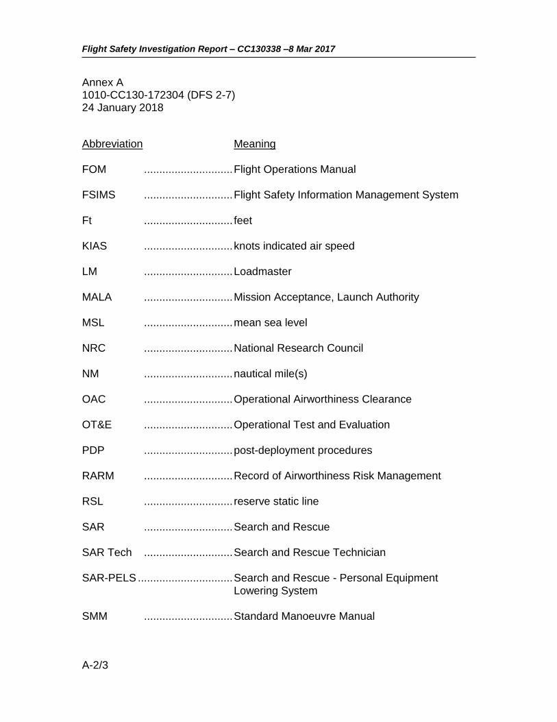
Flight Safety Investigation Report – CC130338 –8 Mar 2017
A-2/3
Annex A 1010-CC130-172304 (DFS 2-7) 24 January 2018
Abbreviation Meaning
FOM ............................. Flight Operations Manual
FSIMS ............................. Flight Safety Information Management System
Ft ............................. feet
KIAS ............................. knots indicated air speed
LM ............................. Loadmaster
MALA ............................. Mission Acceptance, Launch Authority
MSL ............................. mean sea level
NRC ............................. National Research Council
NM ............................. nautical mile(s)
OAC ............................. Operational Airworthiness Clearance
OT&E ............................. Operational Test and Evaluation
PDP ............................. post-deployment procedures
RARM ............................. Record of Airworthiness Risk Management
RSL ............................. reserve static line
SAR ............................. Search and Rescue
SAR Tech ............................. Search and Rescue Technician
SAR-PELS ............................... Search and Rescue - Personal Equipment Lowering System
SMM ............................. Standard Manoeuvre Manual

Flight Safety Investigation Report – CC130338 –8 Mar 2017
A-3/3
Annex A 1010-CC130-172304 (DFS 2-7) 24 January 2018
Abbreviation Meaning
SSO ............................. Senior Staff Officer
T&R ............................. Transport and Rescue
TAC ............................. Technical Airworthiness Clearance
TL ............................. Team Lead
TM ............................. Team Member
TRSET ............................. Transport and Rescue Standards and Evaluation Team
VHF ............................. very-high frequency

Flight Safety Investigation Report – CC130338 –8 Mar 2017
B-1
Annex B 1010-CC130-172304 (DFS 2-7) 24 January 2018
ANNEX B – FIGURES AND TABLES
Figure 1: Accident Area Map (Base map from Google Maps) ............................... 2
Figure 2: TM Canopy and Harness in situ, looking southeast. .............................. 4
Figure 3: CSAR 7(A) Main Canopy Schematic ..................................................... 9
Figure 4: CSAR 7(A) Harness and Pack ............................................................. 11
Figure 5: SAR-PELS attached and released ....................................................... 14
Figure 6: Parachutist Wrist Altimeter ................................................................... 17
Table 1: Personnel Information ............................................................................. 5