Causes of Transfomer Failures
62
UNIVERSITY OF VAASA FACULTY OF TECHNOLOGY ELECTRICAL ENGINEERING Markku Taikina-aho SURVEY OF TRANSFORMER FAILURE CAUSES AND CONSEQUENCES Bachelor’s thesis in Technology for the degree of Bachelor of Science in Technology submitted for inspection in Vaasa, 7 th of September, 2010. Instructor Professor Erkki Antila
-
Upload
patricio-cabo -
Category
Documents
-
view
39 -
download
5
description
distintas causas de fallas de los transformadores
Transcript of Causes of Transfomer Failures
UNIVERSITY OF VAASA
FACULTY OF TECHNOLOGY
ELECTRICAL ENGINEERING
Markku Taikina-aho
SURVEY OF TRANSFORMER FAILURE CAUSES AND CONSEQUENCES
Bachelor’s thesis in Technology for the degree of Bachelor of Science in Technology
submitted for inspection in Vaasa, 7th
of September, 2010.
Instructor Professor Erkki Antila
1
ACKNOWLEDGEMENTS
I’d like to thank Professor Erkki Antila for giving me an interesting topic for my
candidate thesis and for all his guidance and support during the past few months.
I would also like to thank Professor Kimmo Kauhaniemi for his advice and help. I am
also grateful to Energiateollisuus ry (Finnish Energy Industries) and to all companies
that answered my inquiry form and made this research possible.
2
TABLE OF CONTENTS page
ACKNOWLEDGEMENTS 1
ABBREVIATIONS AND SYMBOLS 4
ABSTRACT 5
1. INTRODUCTION 6
2. TRANSFORMER 7
2.1. Definition of a transformer 8
2.2. Connections and vector groups 8
2.3. Transformer structure 11
2.4. Transformer components and materials 12
2.4.1. Transformer core 12
2.4.2. Windings 12
2.4.3. Tap changer 13
2.4.4. Transformer oil 13
3. TRANSFORMER FAILURES AND AGEING 16
3.1. Classification of faults and failure modes 16
3.2. Transformer faults and causes 21
3.3. Transformer insulation ageing and remaining life 24
3.4. Consequences of transformer failure 25
4. TRANSFORMER FAILURE INQUIRY 27
5. RESULTS AND ANALYSIS OF INQUIRY 28
5.1. Component, where failure occurred 29
5.2. Age of the failed transformer 31
5.3. Repair and interruption time of failed transformer 32
5.4. Causes of failures 34
5.5. Consequences of transformer failure 36
5.6. Inspections done to failed transformers 38
3
5.7. Methods that may have prevented the failure 39
6. CONCLUSIONS 42
REFERENCES 44
APPENDICES 46
APPENDIX 1. Inquiry form in Finnish 46
APPENDIX 2. Inquiry form in English 54
4
ABBREVIATIONS AND SYMBOLS
A.C.
D.C.
DGA
DP
Alternating current
Direct current
Dissolved gas analysis
Degree of Polymerization
HV
KAH
LV
MV
High-voltage
Customer outage cost, Keskeytyksestä aiheutunut haitta
Low-voltage
Medium-voltage
5
UNIVERSITY OF VAASA
Faculty of technology
Author: Markku Taikina-aho
Topic of the thesis: Survey of transformer failure causes and
consequences
Instructor: Erkki Antila
Degree: Bachelor of Science in Technology
Department: Department of Electrical Engineering and
Automation
Degree Programme: Degree Programme in Electrical and Energy
Engineering
Major of Subject: Electrical Engineering
Year of Entering the University: 2005
Year of Completing the Thesis: 2010 Pages: 61
ABSTRACT:
Transformers are one of the most important components of the power grid. As
transformers age, their failure risk increases. Therefore, condition management is
needed, and it plays a very important role in preventing these failures and in making the
grid operate correctly.
This thesis aims to clarify transformer failures, their numbers, causes and consequences.
An inquiry related to transformer faults was sent to Finnish grid companies and biggest
industrial plants and to Swedish, Norwegian and Danish grid companies, and to
European transmission system operators. By sending out this inquiry, it was possible to
gather practical information about transformer failures.
It was discovered that the most faulted component of transformer was windings and the
three leading causes for failure were voltage peak/surge, winding failure and insulation
failure. Almost 50 % of transformers failed at the age of 20–40 years. On 38 % of
failures, repair and interruption time was 1–4 hours.
Some of the most severe consequences of failure were transformer oil leak to
environment and transformer fires. The percentage of failed transformers in company
between years 2000 and 2010 was 2.53 % and yearly rate is thus 0.253 %.
The inquiry did show the meaning and the need of condition management.
KEYWORDS: Transformer, Transformer failure, Transformer fault, Condition
management.
6
1. INTRODUCTION
The topic of this thesis is transformer faults. The main purpose of this thesis is to clarify
transformer faults, their reasons, numbers and consequences. This study is a part of
research program arranged by CLEEN ltd (Cluster for Energy and Environment). The
research program is called SGEM (Smart Grids and Energy Markets) and it consists of
several work packages. This thesis belongs to work package 4.5: Condition mana-
gement as real-time process. The topic of the thesis was suggested by Professor Erkki
Antila from the Department of Electrical Engineering and Automation at the University
of Vaasa.
The transformer is one of the most important parts of power-distribution network. When
transformer fault occurs, power delivery to its area is interrupted which causes
inconvenience to power consumers. However, transformer failure may also cause
material damage, environmental damage and even personal injury in the worst case.
Condition management has an important role to prevent damages caused by transformer
faults. When these faults are solved and prevented quickly and properly, power
consumers are content, savings are made and damage caused by fault is minimized.
This thesis consists of six chapters. The following two chapters are meant to introduce
the reader to transformer structure and components and present transformer faults
generally. The fourth chapter presents the inquiry form and the way the inquiry was
done and the fifth chapter presents the results and analysis of the survey. Finally the
conclusions of the survey and thesis are drawn in the last chapter.
The results of this survey are applied both in SGEM program and related research
activities in the universities and industry. Results will also be utilized in VAHA-project
(VAHA–Distribution Automation and ICT development).
7
2. TRANSFORMER
The main purpose of a transformer is to change the magnitude of alternating voltage. As
the transformers became common in the beginning of twentieth century, the result was
that A.C. power displaced D.C. power almost completely. A.C. power systems are fairly
more used to transfer and distribute power than D.C. power systems, mainly due to
good features of the transformers. However, as the electronic power converters are
improved, the usage of D.C. voltages has increased in power transmission of great
distances.
The transformer’s most important functions from the power systems point of view are
adjusting of voltage to a suitable value in different parts of power grid, separation of
different voltage levels from each other and limiting the short-circuit current in
distribution networks. (Korpinen 1998.)
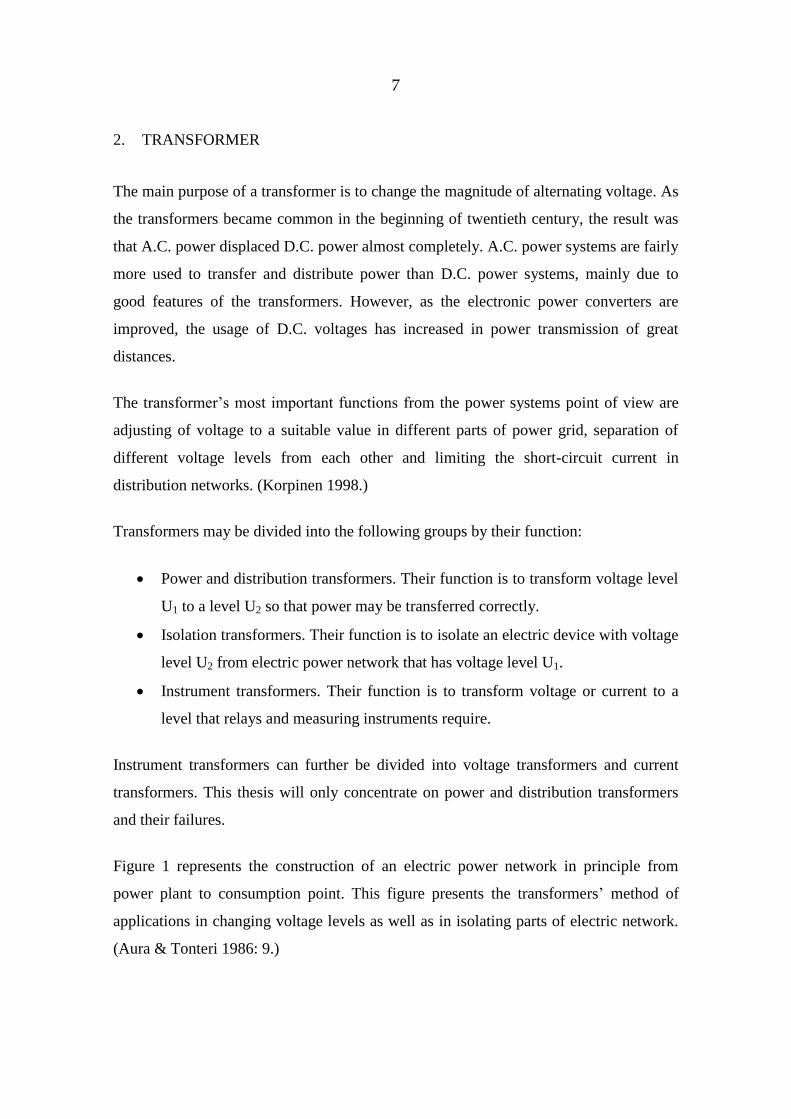
Transformers may be divided into the following groups by their function:
Power and distribution transformers. Their function is to transform voltage level
U1 to a level U2 so that power may be transferred correctly.
Isolation transformers. Their function is to isolate an electric device with voltage
level U2 from electric power network that has voltage level U1.
Instrument transformers. Their function is to transform voltage or current to a
level that relays and measuring instruments require.
Instrument transformers can further be divided into voltage transformers and current
transformers. This thesis will only concentrate on power and distribution transformers
and their failures.
Figure 1 represents the construction of an electric power network in principle from
power plant to consumption point. This figure presents the transformers’ method of
applications in changing voltage levels as well as in isolating parts of electric network.
(Aura & Tonteri 1986: 9.)
8
Figure 1. Transformers in electric power network. 1) Power transformer 2) Power
transformer in medium voltage grid 3) Distribution transformer.
Translated to English. (Aura & Tonteri 2005: 268.)
2.1. Definition of a transformer
A transformer is a static device consisting of a winding, or two or more coupled
windings, with or without a magnetic core, for inducing mutual coupling between
circuits. Transformers are used in electric power systems to transfer power by
electromagnetic induction between circuits at the same frequency with changed values
of voltage and current. (Winders 2002: 1.)
2.2. Connections and vector groups
Phase winding connections of a three-phase transformer may be done using three ways:
9
Y-connection (star connection), where one end of the windings are connected
together in star point.
D-connection (delta connection), where windings are connected in series
(triangle form).
Z-connection (zigzag connection, interconnected star).
Every type of connection has advantages and disadvantages. Zigzag winding is only
used in distribution transformer’s LV-side windings. It acts like a normal Y-connection;
in addition it allows asymmetric loading but does not distort voltage. (ABB Oy 2004:
157, Aura 2005: 282.)
The connections of a three-phase transformer are standardized. These connections are
divided into four groups, which are classified by a number (0, 5, 6, and 11). Every
connection group has 3 different connections, so in practice a transformer may be
connected in 12 different ways.
These vector groups are marked with symbol letters. The letters that represent the
connection are defined as follows:
Y is star-connected HV winding
D is delta-connected HV winding
y is star-connected LV winding
d is delta-connected LV winding
z is zigzag-connected LV winding
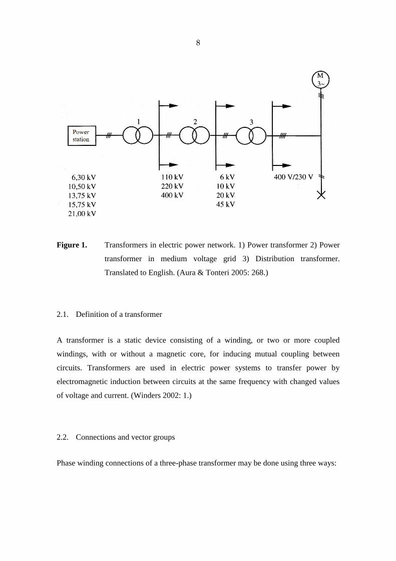
Figure 2 represents standardized vector groups of a three-phase transformer. The most
commonly used vector groups in Finland are marked out. (Aura 2005: 281–282.)
10
Figure 2. Standardized vector groups of a three-phase transformer. Picture
translated to English. (Aura 2005: 281.)
If a transformer has neutral point at the HV-side, it is marked with letter N and LV-side
neutral point with letter n. (Aura 2005:282.)
In addition, independent windings at the HV-side are marked with letters III and the
LV-side with letters iii.
Depending on the type of winding connection, voltage phase displacement follows. This
phase shift is described with clock hour number. The number presents the clock hour of
the LV side phase vectors when the HV side phase vectors point to clock hour 12. For
example, clock notation 11 means that the HV-side phase angle lags the LV by 30
degrees. When clock hour is 0, no phase shift happens. (ABB Oy 2000: 315.)
11
2.3. Transformer structure
Transformers can be divided into power transformers and distribution transformers. The
term power transformer refers to those transformers, which are located between the
generator and distribution circuits. Distribution transformer takes voltage from a
primary distribution circuit and reduces it to a secondary distribution circuit or a
consumer’s service circuit. (Harlow 2004: 2-2, 2-23.)
A transformer has both active and passive parts. Active parts include windings and iron
core, which carry out the primary task of a transformer. Passive parts are such as
supporting structure, insulators, transformer oil and cooling devices.
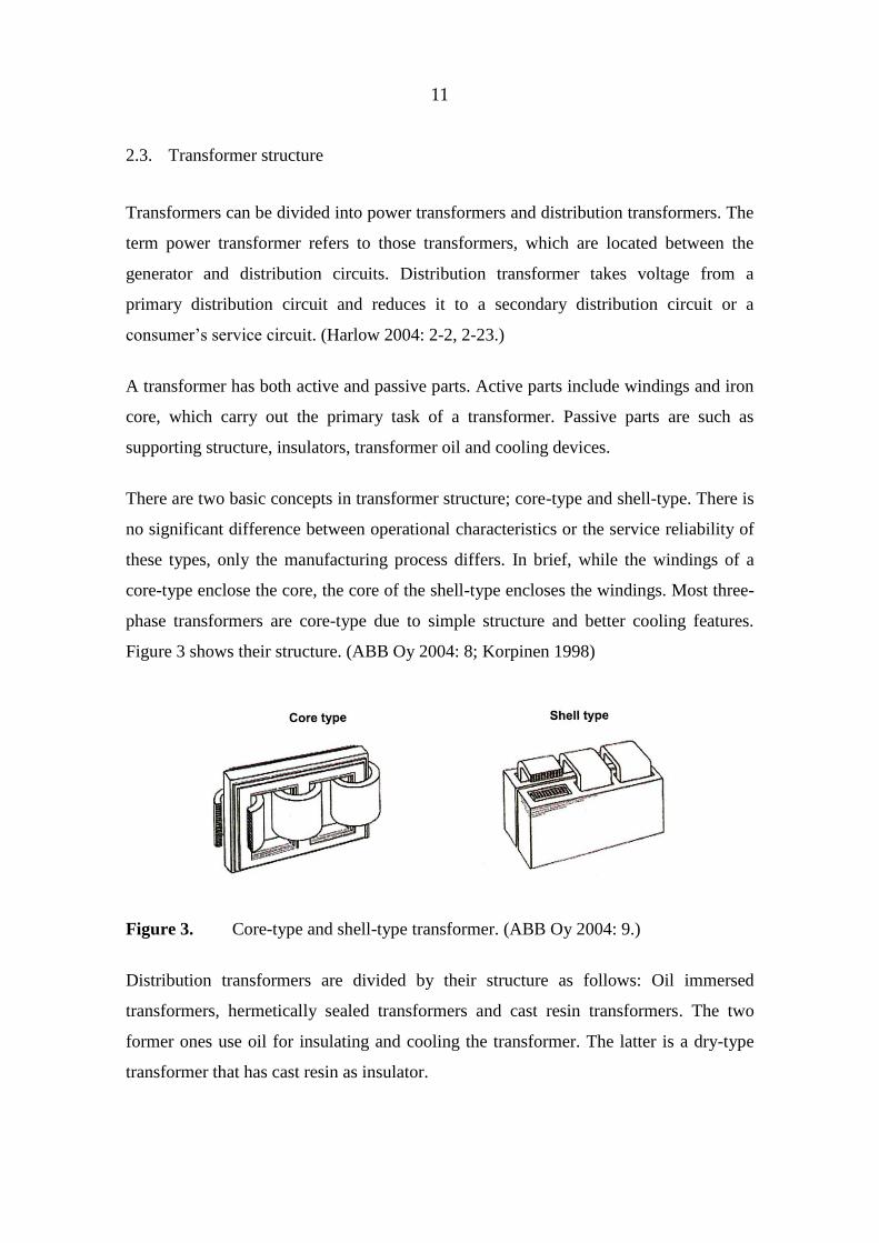
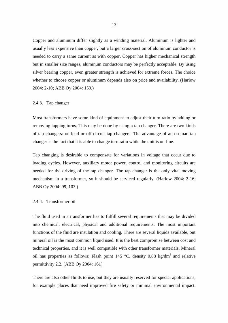
There are two basic concepts in transformer structure; core-type and shell-type. There is
no significant difference between operational characteristics or the service reliability of
these types, only the manufacturing process differs. In brief, while the windings of a
core-type enclose the core, the core of the shell-type encloses the windings. Most three-
phase transformers are core-type due to simple structure and better cooling features.
Figure 3 shows their structure. (ABB Oy 2004: 8; Korpinen 1998)
Figure 3. Core-type and shell-type transformer. (ABB Oy 2004: 9.)
Distribution transformers are divided by their structure as follows: Oil immersed
transformers, hermetically sealed transformers and cast resin transformers. The two
former ones use oil for insulating and cooling the transformer. The latter is a dry-type
transformer that has cast resin as insulator.
12
The most common transformer type is an oil immersed distribution transformer that has
an oil conservator. Hermetically sealed transformers have no oil conservator. The oil
tank is designed to withstand overpressure caused by overload. Typically an inhibitor is
added to the oil to slow down aging. (Korpinen 1998.)
Cast resin transformers are meant to be used in places where liquid filled transformers
are not allowed because of fire or pollution danger. (Aura 2005: 288.)
2.4. Transformer components and materials
As mentioned, a transformer has both active and passive parts. Here, some of the most
important parts are described with a few words.
2.4.1. Transformer core
The function of the core is to provide a magnetic path to channel the flux. It consists of
thin sheets of steel called laminations, which are insulated from each other to reduce
eddy current losses. The insulating coating is thin, less than 4 µm. Also the steel sheets
are thin, their typical thickness varies from 0.18 mm to 0.30 mm.
The core steel has very low carbon content, less than 0.1 %. Carbon has negative
influence on the hysteresis losses and transformer ageing properties. On the other hand,
some silicon is added to the steel to reduce eddy currents. The silicon level is kept
below 3 % because an increased level will make the core brittle. (Harlow 2004: 2-8;
ABB Oy 2004: 159.)
2.4.2. Windings
The windings are conductors that carry current and are wound around the sections of
core. They have to be properly insulated, supported and cooled to function and
withstand operational conditions. The main materials used in transformer windings are
copper and aluminum.
13
Copper and aluminum differ slightly as a winding material. Aluminum is lighter and
usually less expensive than copper, but a larger cross-section of aluminum conductor is
needed to carry a same current as with copper. Copper has higher mechanical strength
but in smaller size ranges, aluminum conductors may be perfectly acceptable. By using
silver bearing copper, even greater strength is achieved for extreme forces. The choice
whether to choose copper or aluminum depends also on price and availability. (Harlow
2004: 2-10; ABB Oy 2004: 159.)
2.4.3. Tap changer
Most transformers have some kind of equipment to adjust their turn ratio by adding or
removing tapping turns. This may be done by using a tap changer. There are two kinds
of tap changers: on-load or off-circuit tap changers. The advantage of an on-load tap
changer is the fact that it is able to change turn ratio while the unit is on-line.
Tap changing is desirable to compensate for variations in voltage that occur due to
loading cycles. However, auxiliary motor power, control and monitoring circuits are
needed for the driving of the tap changer. The tap changer is the only vital moving
mechanism in a transformer, so it should be serviced regularly. (Harlow 2004: 2-16;
ABB Oy 2004: 99, 103.)
2.4.4. Transformer oil
The fluid used in a transformer has to fulfill several requirements that may be divided
into chemical, electrical, physical and additional requirements. The most important
functions of the fluid are insulation and cooling. There are several liquids available, but
mineral oil is the most common liquid used. It is the best compromise between cost and
technical properties, and it is well compatible with other transformer materials. Mineral
oil has properties as follows: Flash point 145 °C, density 0.88 kg/dm3
and relative
permittivity 2.2. (ABB Oy 2004: 161)
There are also other fluids to use, but they are usually reserved for special applications,
for example places that need improved fire safety or minimal environmental impact.
14
They are also 5–6 times more expensive than mineral oil. These fluids are (ABB Oy
2004: 162):
Dimethyl silicone (Flash point 310 °C, density 0.96 kg/dm3, relative permittivity
2.7)
Synthetic ester (Flash point 275 °C, density 0.97 kg/dm3, relative permittivity
3.2)
Synthetic hydrocarbon (Flash point 230 °C, density 0.83 kg/dm3, relative
permittivity 2.1)
Agricultural ester (Flash point 330 °C, density 0.91 kg/dm3, relative permittivity
3.2)
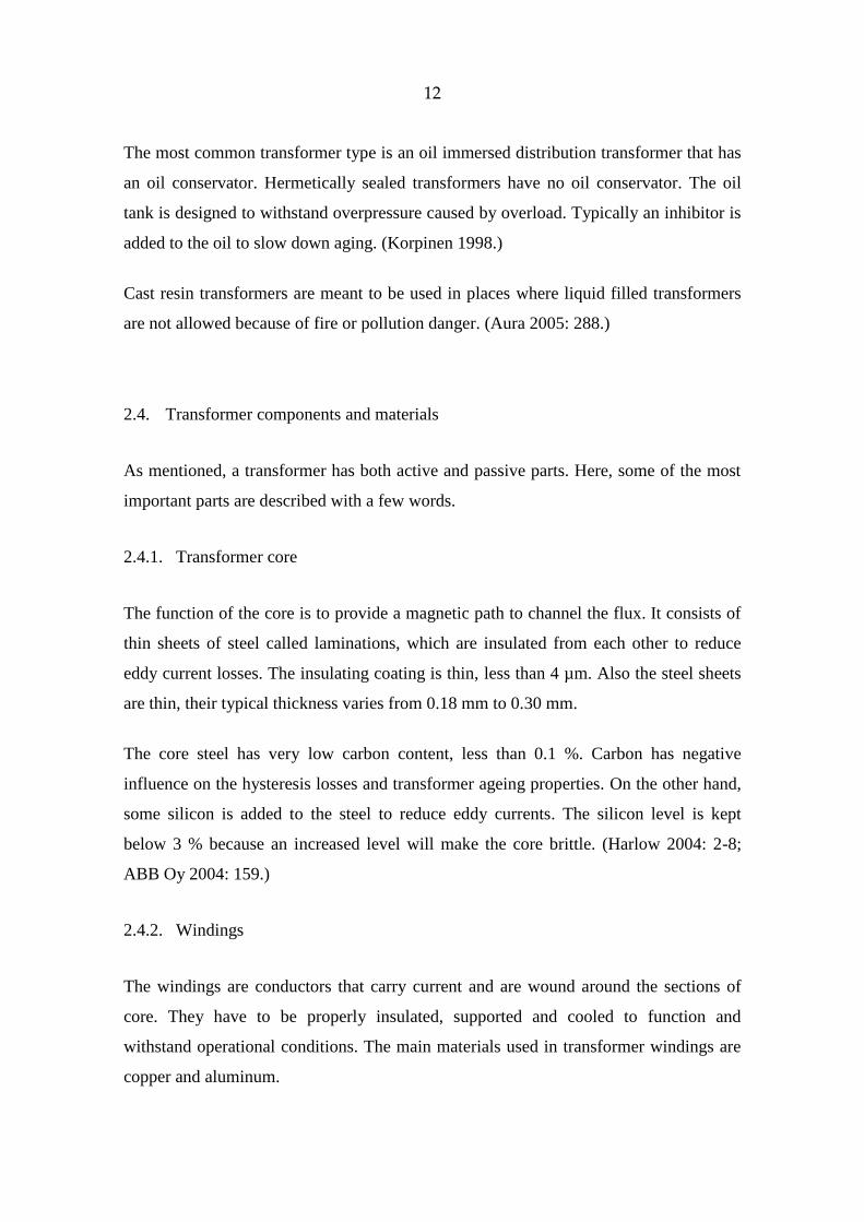
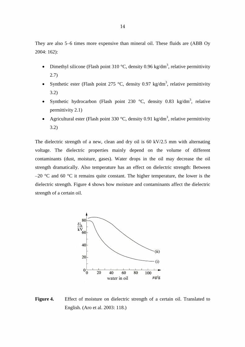
The dielectric strength of a new, clean and dry oil is 60 kV/2.5 mm with alternating
voltage. The dielectric properties mainly depend on the volume of different
contaminants (dust, moisture, gases). Water drops in the oil may decrease the oil
strength dramatically. Also temperature has an effect on dielectric strength: Between
–20 °C and 60 °C it remains quite constant. The higher temperature, the lower is the
dielectric strength. Figure 4 shows how moisture and contaminants affect the dielectric
strength of a certain oil.
Figure 4. Effect of moisture on dielectric strength of a certain oil. Translated to
English. (Aro et al. 2003: 118.)
15
In the figure, curve (i) represents technically clean oil that has contaminants 55 µg/g and
curve (ii) represents the same oil filtered twice.
Like organic matters, oil will also gradually oxidize. High temperature accelerates this
phenomenon. Depending on the composition of the oil, chemical reactions will lead to
different results. Some oils generate acid compounds that damage the paper insulation
while with other oils oxidization will lead to sedimentation, which affects the cooling
properties by weakening it. Also possible partial discharges affect the properties of the
oil. However, the properties of the oil and the possible faults in the transformer can be
defined by analyzing the oil with different means. The most popular method is
dissolved gas analysis (DGA), where the percentages of gases are investigated. These
gases include hydrogen, methane, acetylene, ethylene and ethane, among others. Gas
content rates are used to analyze possible faults. For example, if the oil includes more
hydrogen than methane, it can be assumed that partial discharges have appeared in the
oil. (Aro et al. 2003: 119, 197–198.)
16
3. TRANSFORMER FAILURES AND AGEING
The modern interconnected power system requires reliable power transformers. Their
sizes range from a few kVA to over a few hundred MVA. Power transformers are
usually very reliable and have a relatively long life; 20–35 years. In practice, with
proper maintenance, the life of a transformer may be up to 60 years. However, as
transformers age, their internal condition becomes weaker and the failure risk increases.
The failure of an in-service transformer is dangerous to personnel and the environment
through explosions, fire and oil leakage. It is also costly to repair or replace, and may
bring down revenues significantly. A new transformer has the mechanical and electrical
strength to withstand unusual system conditions, such as lightning strikes and short-
circuits, but as transformers age, their insulation and strength may weaken to the point
where they cannot withstand these conditions any more and failure occurs. In addition, a
certain fault may develop which results in faster ageing and increases the probability of
failure even more.
3.1. Classification of faults and failure modes
A transformer fault may take place as a sum of different conditions and causes. The
definition of transformer failure may be described as follows:
transformer damage in service causes a forced outage
trouble takes place and requires the removal of the transformer for return to a
repair facility, or field repair.
Transformer failures can be basically divided into electrical, mechanical and thermal
failures. The cause of failure can be categorized as internal or external. (Wang &
Vandemaar & Srivastava 2002)
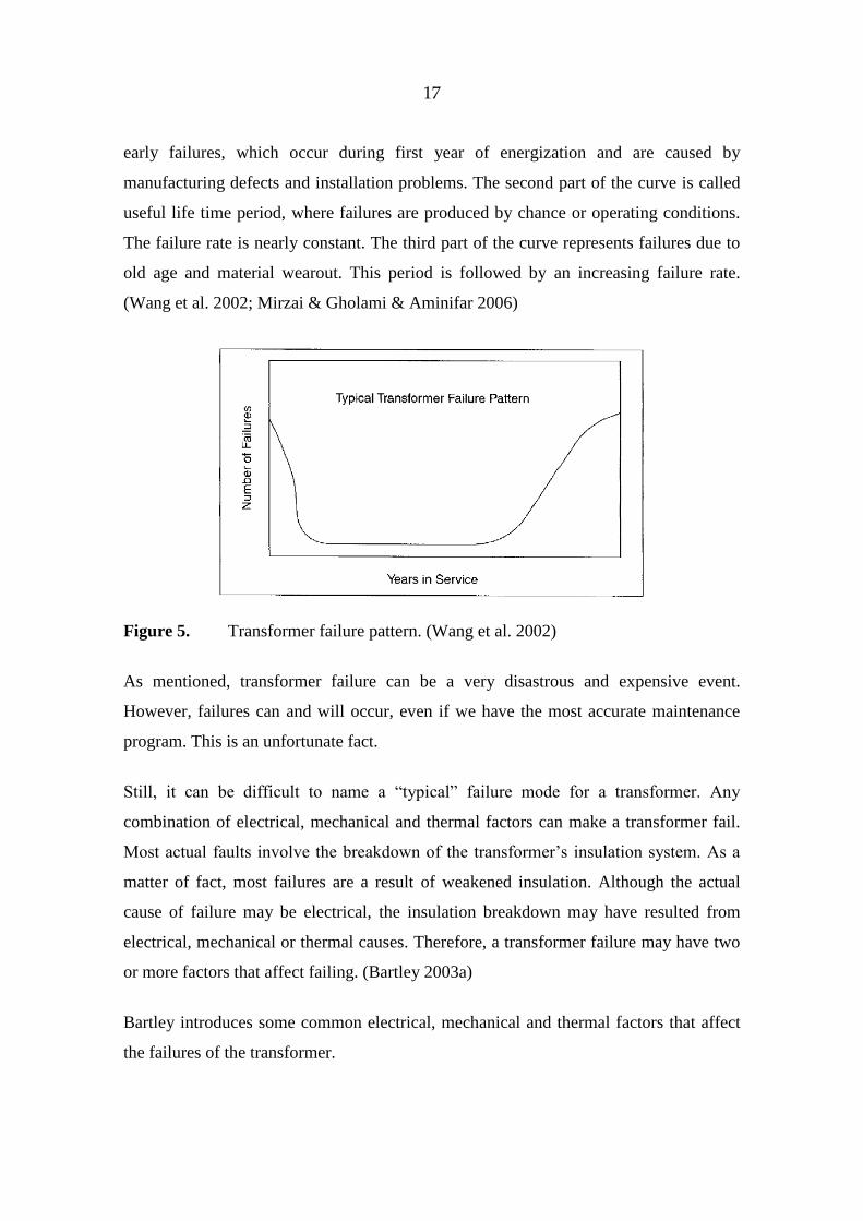
Transformer failures have a pattern called “bathtub”, which is shown in figure 5. The
pattern can be divided into three failure modes. The first part of the curve represents
17
early failures, which occur during first year of energization and are caused by
manufacturing defects and installation problems. The second part of the curve is called
useful life time period, where failures are produced by chance or operating conditions.
The failure rate is nearly constant. The third part of the curve represents failures due to
old age and material wearout. This period is followed by an increasing failure rate.
(Wang et al. 2002; Mirzai & Gholami & Aminifar 2006)
Figure 5. Transformer failure pattern. (Wang et al. 2002)
As mentioned, transformer failure can be a very disastrous and expensive event.
However, failures can and will occur, even if we have the most accurate maintenance
program. This is an unfortunate fact.
Still, it can be difficult to name a “typical” failure mode for a transformer. Any
combination of electrical, mechanical and thermal factors can make a transformer fail.
Most actual faults involve the breakdown of the transformer’s insulation system. As a
matter of fact, most failures are a result of weakened insulation. Although the actual
cause of failure may be electrical, the insulation breakdown may have resulted from
electrical, mechanical or thermal causes. Therefore, a transformer failure may have two
or more factors that affect failing. (Bartley 2003a)
Bartley introduces some common electrical, mechanical and thermal factors that affect
the failures of the transformer.
18
Electrically induced factors typically damage the insulation system of a transformer.
Common factors are (Bartley 2003a):
Transient or sustained over-voltage conditions.
Exposure to voltage surges.
Partial discharge.
Static electrification.
Transformer operation under transient or sustained over-voltage conditions may result
in overstressing the insulation and overheating of the core. Lightning and switching
surges can cause serious damage to a transformer’s electrical and mechanical features
and components. A transformer that has failed due to these conditions generally
displays damage near the line-end terminals. Partial discharge can be described as low
intensity arching and it has the effect of damaging conductors and insulation. Poor
insulator design, manufacturing defects and contamination of the insulation system
cause partial discharges. Static electrification is a problem in very high voltage
transformers (over 345 kV). A static charge is developed between the oil and the metal
components when the oil temperature is low and circulation of the thickened oil
happens rapidly. When the charge increases and becomes greater than the insulating
oil’s dielectric capacity, a flashover happens and destroys the transformer or damages it
severely.
Mechanically induced factors typically cause winding deformation and result in
abrasion or rupturing of a transformer’s insulation. Severe damage may lead to
electrical failure. It depends on the severity of the damage how long a transformer can
function correctly. Winding deformation can be developed in two ways: Shipping
damage or electromechanical forces. Common mechanical factors are (Bartley 2003a):
Hoop buckling of the innermost winding.
Conductor tipping.
Conductor telescoping.
Spiral tightening.
End-ring crushing.
19
Failure of the coil clamping system.
Displacement of a transformer’s incoming and outgoing leads.
Hoop buckling of the innermost winding happens when the conductor will buckle
inward toward the core insulating cylinder. The paper insulation will be damaged in
severe cases of buckling. It depends on the degree of damage whether the failure occurs
immediately. Conductor tipping is a problem in transformers, which have helical
windings made of Continuously Transposed Cable and have paper insulation. Here,
axial forces exceed the CTC bundle’s compressive capability and the bundle tips tearing
open the paper insulation and exposing the conductor. An electrical failure will usually
occur immediately. Conductor telescoping is a problem which is associated with layer
windings made up of thin flat conductors that are supported end-to-end. Axial forces
cause individual conductors to telescope over one another. The paper insulation is
damaged and the entire layer becomes mechanically unstable. Spiral tightening happens
as layer windings tighten as a result of radial forces. This will affect the paper insulation
by damaging it and making it mechanically unstable. End-ring crushing happens when
the winding’s axial forces exceed the mechanical strength of the radial end ring at the
bottom of the winding and cause mechanical instability of the entire winding. Failure of
the coil clamping system happens when the coil clamping system restrains the coils
from movement caused by electromechanical forces. These forces result from large
sudden increases in current flow and they try to spread the winding coils apart axially.
When a coil clamping system fails, depending on the restraining force and current
increase, the transformer may operate normally for a period of time or the failure may
result in severe deformation of the coils and damage the insulation. Electrical failure can
occur immediately. Displacement of a transformer’s incoming and outgoing leads may
happen when the connection of the transformer leads break in the area where they live
the windings. Sometimes the lead supports can break too.
Thermally induced factors have an effect on the loss of physical strength of the
insulation. A well-designed, properly operated and maintained transformer and
insulation system should service for 20 to 30 years or more. Common thermal factors
are (Bartley 2003a):
20
Overload.
Cooling system failure.
Axial oil duct spaces blockage.
Overexcited condition.
Operating of a transformer under challenging temperature conditions.
Cooling system failures may include failures of the oil pumps or directed flow oil
distribution system as well as blocking or fouling of the coolers. Blockage of axial oil
duct spaces limits the amount of cooling oil to the windings in the immediate area.
Operating a transformer in an over-voltage or under-frequency condition may cause
excessive stray magnetic flux to overheat insulation severely.
There are also other ways to classify transformer faults. One way is to classify faults by
their location. This includes faults in the auxiliary equipment, faults in the transformer
windings and connections, and overloads and external short circuits.
Transformer auxiliary equipment includes:
Transformer oil. If the oil drops under normal level exposing energized parts,
severe things may happen.
Gas cushion. If moisture and oxygen can’t access the gas space, oil and
insulation life time is much greater.
Oil pumps and air fans. Oil temperature increase may be a sign of overload or
failure in the cooling system.
Core and winding insulations.
Minor insulation failures can develop into major failures if not taken care of early.
Insulation failure may be caused by damage or poor quality of insulation of laminations
and core bolts, poor quality of insulation between windings, between winding and core,
or conductor insulation. It may have been damaged mechanically or because of ageing
and overloading. Insulation failure may also occur due to poorly made connections or
joints.
21
Winding faults may be divided into two groups that are faults between turns or coil
parts including phase-to-phase faults on the HV and LV terminals or on windings itself
as well as short-circuits between windings, and faults to ground or across winding
including phase-to-earth faults on the HV and LV terminals or on windings.
Mechanical forces or insulation deterioration can cause a point contact, which leads to
short circuit between turns. Excessive overload, loose connections and breakdown of
insulation caused by impulse voltage affect mechanical forces and insulation conditions.
Faults to ground or across windings cause large values of fault currents and oil
decomposition that will generate a lot of gas. Detection of this type of fault is not
difficult, but fast repair is necessary to avoid damage and system instability.
Overloads that last long periods of time result deterioration of insulation, which will
lead to a fault afterwards. Insulation weakens because of temperature rise caused by
overload. (Ravindranath & Chander 2005: 135–137.)
3.2. Transformer faults and causes
When troubleshooting transformer faults and their causes, the following conditions may
be taken into account:
Breakdown of pressure-relief diaphragm results from an internal fault that
causes excessive internal pressures or a too high transformer liquid level.
Bushing failure can result from flashover, resulting from dirt accumulation or
lightning.
Core failure is caused by failures of core lamination, the core itself, clamps etc.
Discoloration of transformer liquid is usually caused by carbonization of the
liquid. Switching, contaminations or core failure effect carbonization.
Gas-sealed transformer troubles mainly include loss of gas, high oxygen
level, or malfunction of the gas regulator. These troubles usually result from gas
leaks, leaky valve seats, or other gas space problems.
22
High exciting current usually results from a short-circuited core or open core
joints.
Incorrect secondary voltage may be due to shorted turns in the transformer,
faulty primary voltage or improper turns ratio.
Internal arcing can be caused by loose connections, dielectric failure, or a low
liquid level that exposes energized parts.
Low dielectric strength may be caused by moisture that reaches the transformer
and condensates.
Moisture condensation is caused by improper ventilation in open-type
transformers. In sealed-type transformers, moisture condensation results from a
cracked diaphragm or leaking gaskets.
Overtemperature may be caused by overcurrent, overvoltage, defective
cooling, low liquid level or sludge in the transformer liquid, high ambient
temperature or a short-circuited core. Clogged air ducts cause overtemperature
in dry-type transformers.
Oxidation of oil is due to high operation temperatures and air. Oxidation will
usually lead to contamination of the transformer liquid.
Transformer liquid leakage is mainly due to improper assembly, filters or
finishing of surfaces, poor joints, bad material or inadequate tightness of parts.
Leakage may occur through screw joints, welds, gaskets etc.
Transformer switching equipment troubles include problems with tap
changers and other switching equipment. These problems can be excessive
contact wear, mechanism overtravel and moisture condensation in the
mechanism liquid, among others.
Winding insulation failure involving short circuits such as phase-to-ground,
phase-to-phase, three-phase with or without ground, or turn-to-turn-type short
circuits. Lightning, short-circuit fault, overload or overcurrent condition,
moisture and contamination of the transformer liquid may cause this failure.
(Gill 2009: 273–275.)
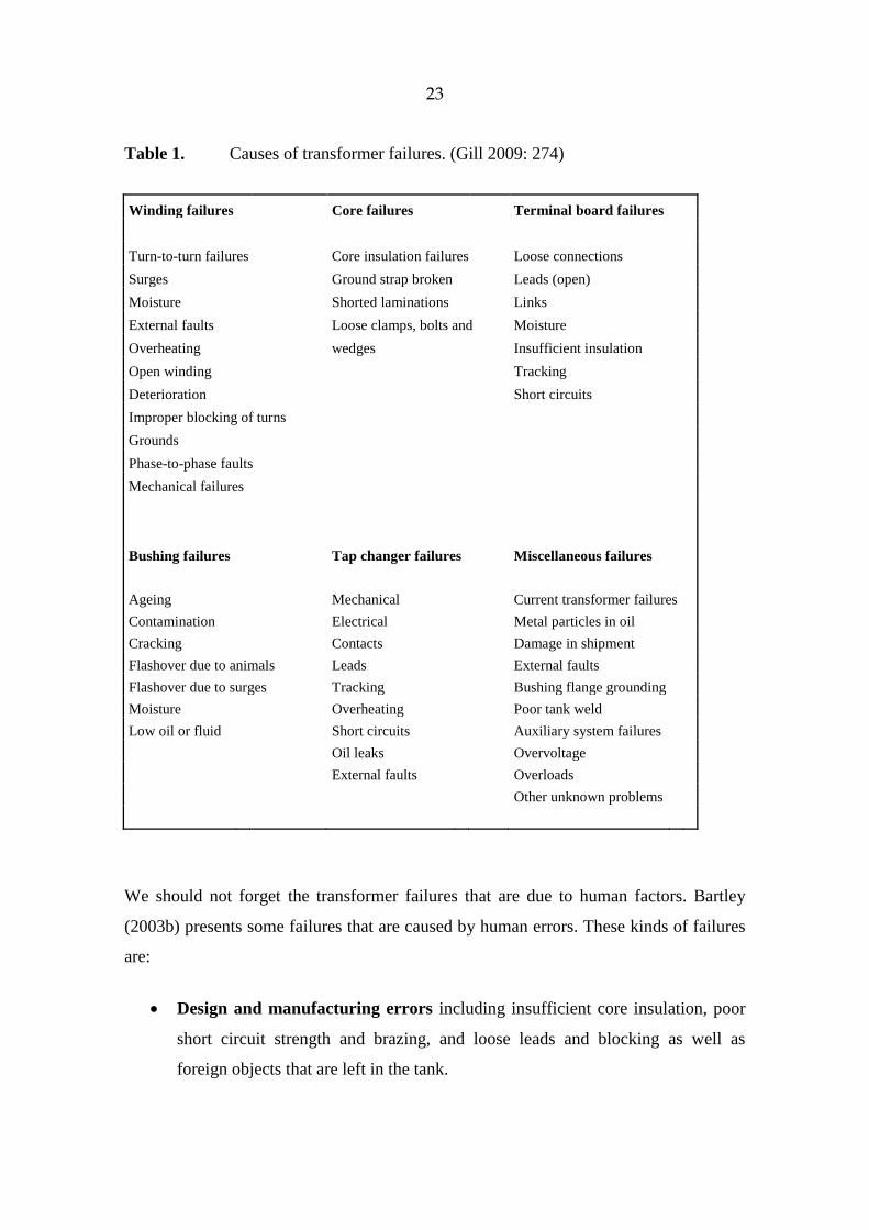
The most common causes of transformer failures are listed in table 1. This table shows
components and faults that arise in them.
23
Table 1. Causes of transformer failures. (Gill 2009: 274)
Winding failures Core failures Terminal board failures
Turn-to-turn failures Core insulation failures Loose connections
Surges
Ground strap broken Leads (open)
Moisture
Shorted laminations
Links
External faults
Loose clamps, bolts and Moisture
Overheating
wedges
Insufficient insulation
Open winding
Tracking
Deterioration
Short circuits
Improper blocking of turns
Grounds
Phase-to-phase faults
Mechanical failures
Bushing failures
Tap changer failures Miscellaneous failures
Ageing
Mechanical
Current transformer failures
Contamination
Electrical
Metal particles in oil
Cracking
Contacts
Damage in shipment
Flashover due to animals Leads
External faults
Flashover due to surges Tracking
Bushing flange grounding
Moisture
Overheating
Poor tank weld
Low oil or fluid
Short circuits
Auxiliary system failures
Oil leaks
Overvoltage
External faults
Overloads
Other unknown problems
We should not forget the transformer failures that are due to human factors. Bartley
(2003b) presents some failures that are caused by human errors. These kinds of failures
are:
Design and manufacturing errors including insufficient core insulation, poor
short circuit strength and brazing, and loose leads and blocking as well as
foreign objects that are left in the tank.
24
Maintenance and operation, which is inadequate or improper. This includes
overloading, moisture and loose connections, as well as improperly set controls,
coolant loss, corrosion and accumulation of dirt and oil. Insufficient
maintenance also includes lack of discovering early troubles.
Ageing was not categorized as a failure cause in the inquiry form sent to the grid
companies.
3.3. Transformer insulation ageing and remaining life
As mentioned, when transformers are ageing their inner condition weakens. This shows
out as transformer oil and insulating system deterioration. Transformer oil is an organic
matter that becomes oxidized as it gets older. Also some metal impurities like copper,
iron and lead, boost oil deterioration. Good transformer oil includes a little inhibite and
it can also be added to the oil to prevent its oxidiation. However, transformer oil ages
easier in higher temperature.
As a result of chemical reactions, transformer oil deteriorates and concretion,
contaminants, water and acid compounds are generated. Water and acid compounds
weaken paper insulation. The measure of paper deterioration is called DP (Degree of
Polymerization). DP of new paper varies from 1000 to 1300. Old transformer insulation
paper can have DP that is only a fifth of its original value. The life of insulation paper is
coming to an end when its DP is 150–200.
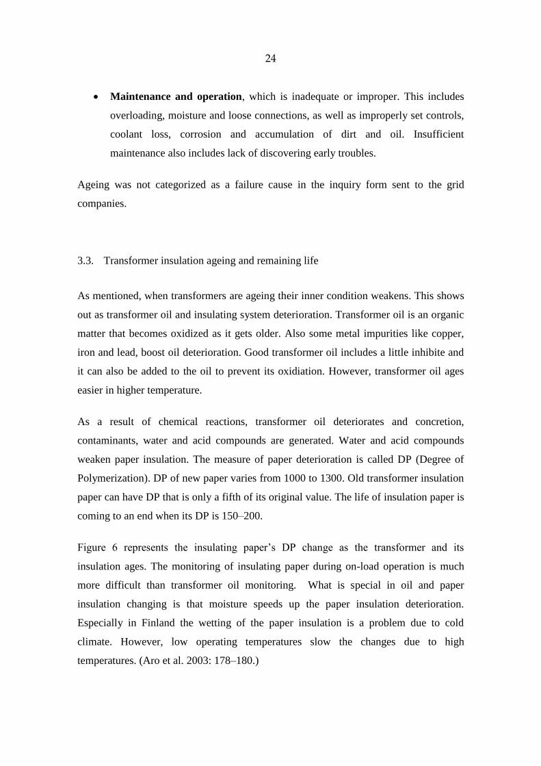
Figure 6 represents the insulating paper’s DP change as the transformer and its
insulation ages. The monitoring of insulating paper during on-load operation is much
more difficult than transformer oil monitoring. What is special in oil and paper
insulation changing is that moisture speeds up the paper insulation deterioration.
Especially in Finland the wetting of the paper insulation is a problem due to cold
climate. However, low operating temperatures slow the changes due to high
temperatures. (Aro et al. 2003: 178–180.)
25
Figure 6. The change of paper insulation’s DP during the transformer’s lifetime.
Translated to English. (Aro et al. 2003: 179).
When transformers age, their remaining life can be calculated by using the Arhennius-
Dakin formula:
Remaining life = TBAe / , (1)
where A is initial life, B is a constant, depending on the properties of the material and T
is the absolute temperature in °K.
However, this method takes only thermal factors into account, so more comprehensive
methods are needed to clarify the remaining life of a trans-former as a whole. This is
where condition assessment and tests are needed to find the other factors affecting the
life of a transformer. (Wang et al. 2002)
3.4. Consequences of transformer failure
Transformer failure may create several consequences. First of all, the failure will cause
damage to the transformer. A transformer can be partially damaged and remain thus
repairable, or it can be totally destroyed with a need for replacement. In some cases,
26
repair or replacement time may be long. Usually transformer failure causes power
delivery interruption to the power consumers of its area. If interruption is long enough,
the grid company has to make up the harm to power consumers.
However, operating transformers in parallel improves reliability on transformer failure;
when one of the transformers gets a fault, power is not interrupted when the load is
moved to other transformer (Vasudevan & Rao & Rao).
Transformer failure can develop a fire or an explosion. In the worst case, this may cause
injuries to bystanders, workers or emergency responders. Environmental harm can also
follow from transformer oil leak. It can damage trees, soil, water and other living things.
(StepUp coalition)
In addition, forest fire or wildfire can be born as a result of transformer fire.
It is clear that the consequences of this kind bring costs. These costs may include
property damage (transformer and other parts nearby), personal injuries, outage costs,
environmental damage correction etc. (StepUp coalition)
However, transformer failure may cause no consequences at all, if the fault is small and
outage can be prevented with a parallel transformer. The consequences depend a lot on
the transformer type and severity of the failure.
27
4. TRANSFORMER FAILURE INQUIRY
At the very beginning of this study it was decided that an inquiry would be sent out to
get some hands-on information about transformer faults. This practical information
would support the theoretical information found in literature. The inquiry was done
using an electronic online form of the University of Vaasa called E-lomake.
The target group of this survey was the electricity grid companies in Finland, Sweden,
Norway and Denmark. Also the inquiry form was sent to the members of ENTSO-E.
Also some of the biggest industrial companies in Finland are taken into account in this
survey.
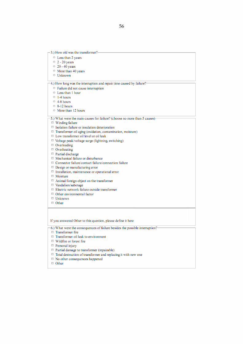
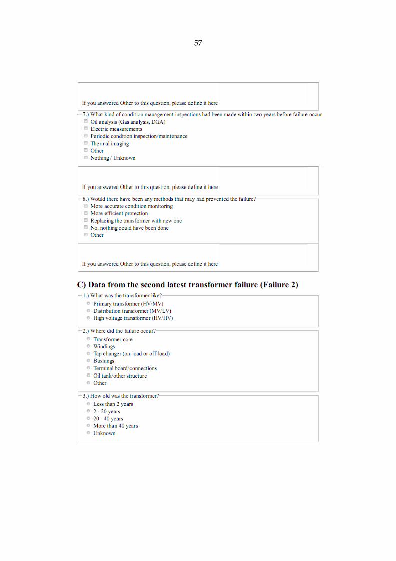
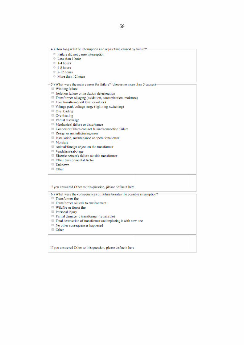
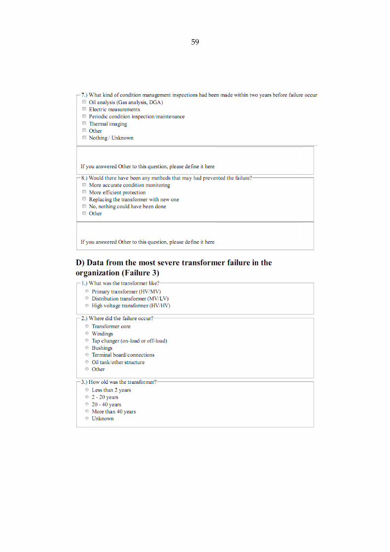
The idea of the inquiry is to clarify transformer failure numbers, their causes and
consequences. The inquiry form is designed to collect some basic information about the
organization’s transformers and two latest failures that have happened. In addition,
information about one of the most severe failures is also gathered, if company has had
one. Details about each failure were asked, such as transformer type, fault place, cause
for failure, transformer age, out-of-service time, consequences, condition assessment
details, and methods that might have prevented the failure. The inquiry form is found at
the end of this study as an appendix. The inquiry was designed to be asked both in
Finnish and English.
E-mail addresses were gathered before sending out this inquiry. The Finnish addresses
were mainly got from the membership register of Energiateollisuus ry.
The inquiry was sent out on 14th of April 2010 (Finland) and on 27th of April 2010
(abroad). Deadline for the answers was 16th of May 2010.
28
5. RESULTS AND ANALYSIS OF INQUIRY
Altogether, the number of the companies that answered to the inquiry was 45. The
companies that responded were mainly from Finland (33 companies). From Finland’s
33 respondents, 7 were industrial companies. 4 companies from Sweden, 6 companies
from Norway, one company from Denmark and one transmission system operator from
Latvia also responded to the inquiry.
Altogether information was gathered from 105 failures. The failures were gathered from
transformers as follows:
Distribution transformers: 65 failures
Power transformers (HV/MV): 27 failures
Power transformers (HV/HV): 8 failures
Industrial transformers: 5 failures
During the years 2000–2010, the companies had a varying number of transformer
failures; from 0 failures to 500 failures depending on the size of the company and the
number of transformers. The average number of transformer failures in a company was
24.53 while the median was 5. If we proportion the happened failures to the number of
transformers in company, the percentage of failed transformers is 2.53 % (0.0253
faults/transformer) on average while the median is 1.83 % (0.0183 faults/transformer) in
ten years. Thus, the yearly failure rate is 0.253 % on average while the median is 0.183
%.
The companies had very few severe transformer failures in recent history. Severe
failures were described as failures which cause personal injuries, environmental
damage, major black-outs or large costs. The average number of severe transformer
failures in a company was 0.6 while the median was 0. The number of severe
transformer failures ranged from 0 to 5. On average, the percentage of severe failures in
a company was 0.34 % (0.0034 severe faults/transformer) during last ten years. Thus,
the yearly number is 0.034 %.
29
It can be said that transformers have a very low failure rate and are thus very reliable.
However, when failure happens, it may be a costly and harmful event depending on the
grade of failure and type of transformer. The results gathered from the inquiry are
presented in the following sections question by question.
The transformer categories are distribution transformers, power transformers and
industrial transformers. Here, different power transformers are treated as one group.
Due to the small amount of industrial transformer answers, the results of this group may
not be statistically valid.
5.1. Component, where failure occurred
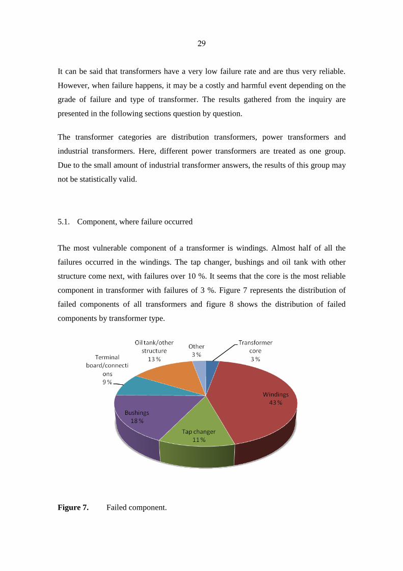
The most vulnerable component of a transformer is windings. Almost half of all the
failures occurred in the windings. The tap changer, bushings and oil tank with other
structure come next, with failures over 10 %. It seems that the core is the most reliable
component in transformer with failures of 3 %. Figure 7 represents the distribution of
failed components of all transformers and figure 8 shows the distribution of failed
components by transformer type.
Figure 7. Failed component.
30
a) b)
c)
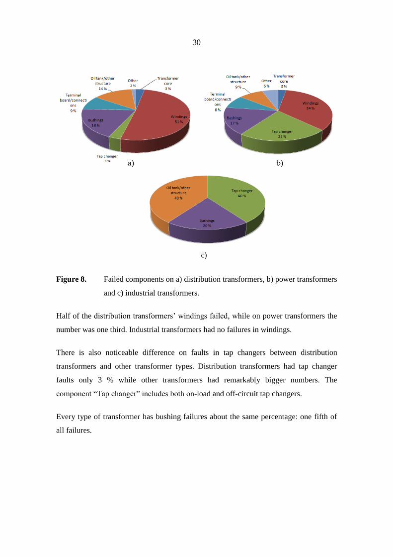
Figure 8. Failed components on a) distribution transformers, b) power transformers
and c) industrial transformers.
Half of the distribution transformers’ windings failed, while on power transformers the
number was one third. Industrial transformers had no failures in windings.
There is also noticeable difference on faults in tap changers between distribution
transformers and other transformer types. Distribution transformers had tap changer
faults only 3 % while other transformers had remarkably bigger numbers. The
component “Tap changer” includes both on-load and off-circuit tap changers.
Every type of transformer has bushing failures about the same percentage: one fifth of
all failures.
31
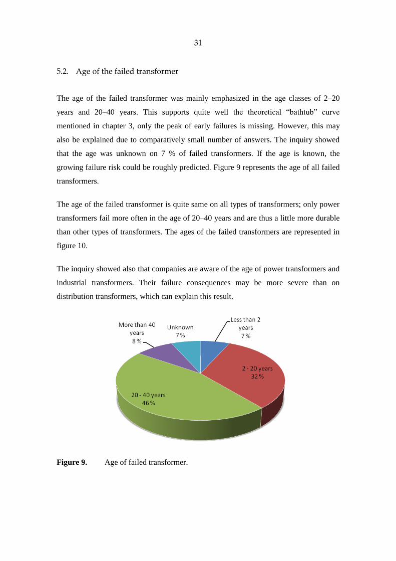
5.2. Age of the failed transformer
The age of the failed transformer was mainly emphasized in the age classes of 2–20
years and 20–40 years. This supports quite well the theoretical “bathtub” curve
mentioned in chapter 3, only the peak of early failures is missing. However, this may
also be explained due to comparatively small number of answers. The inquiry showed
that the age was unknown on 7 % of failed transformers. If the age is known, the
growing failure risk could be roughly predicted. Figure 9 represents the age of all failed
transformers.
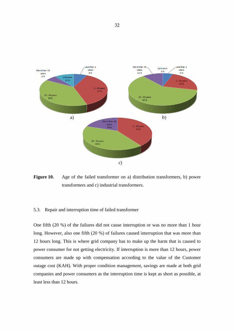
The age of the failed transformer is quite same on all types of transformers; only power
transformers fail more often in the age of 20–40 years and are thus a little more durable
than other types of transformers. The ages of the failed transformers are represented in
figure 10.
The inquiry showed also that companies are aware of the age of power transformers and
industrial transformers. Their failure consequences may be more severe than on
distribution transformers, which can explain this result.
Figure 9. Age of failed transformer.
32
a) b)
c)
Figure 10. Age of the failed transformer on a) distribution transformers, b) power
transformers and c) industrial transformers.
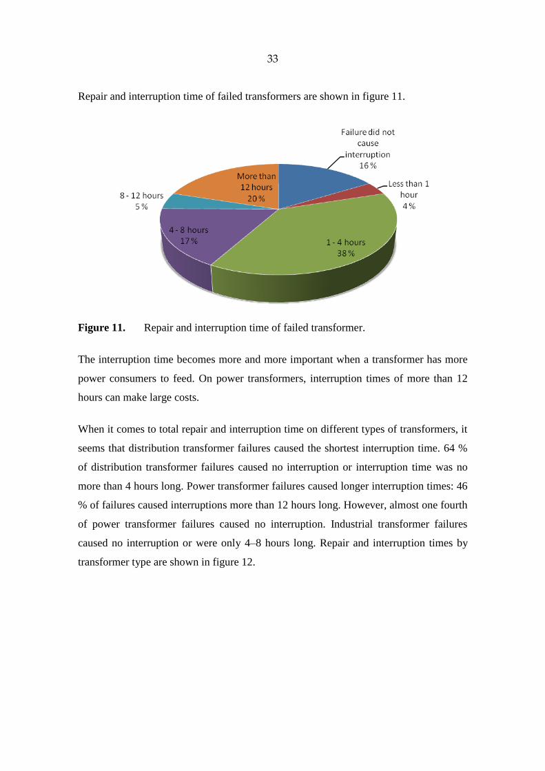
5.3. Repair and interruption time of failed transformer
One fifth (20 %) of the failures did not cause interruption or was no more than 1 hour
long. However, also one fifth (20 %) of failures caused interruption that was more than
12 hours long. This is where grid company has to make up the harm that is caused to
power consumer for not getting electricity. If interruption is more than 12 hours, power
consumers are made up with compensation according to the value of the Customer
outage cost (KAH). With proper condition management, savings are made at both grid
companies and power consumers as the interruption time is kept as short as possible, at
least less than 12 hours.
33
Repair and interruption time of failed transformers are shown in figure 11.
Figure 11. Repair and interruption time of failed transformer.
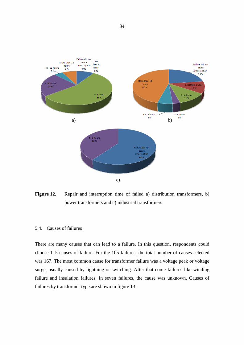
The interruption time becomes more and more important when a transformer has more
power consumers to feed. On power transformers, interruption times of more than 12
hours can make large costs.
When it comes to total repair and interruption time on different types of transformers, it
seems that distribution transformer failures caused the shortest interruption time. 64 %
of distribution transformer failures caused no interruption or interruption time was no
more than 4 hours long. Power transformer failures caused longer interruption times: 46
% of failures caused interruptions more than 12 hours long. However, almost one fourth
of power transformer failures caused no interruption. Industrial transformer failures
caused no interruption or were only 4–8 hours long. Repair and interruption times by
transformer type are shown in figure 12.
34
a) b)
c)
Figure 12. Repair and interruption time of failed a) distribution transformers, b)
power transformers and c) industrial transformers
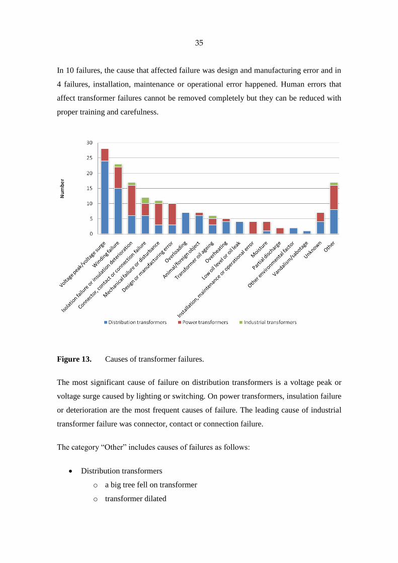
5.4. Causes of failures
There are many causes that can lead to a failure. In this question, respondents could
choose 1–5 causes of failure. For the 105 failures, the total number of causes selected
was 167. The most common cause for transformer failure was a voltage peak or voltage
surge, usually caused by lightning or switching. After that come failures like winding
failure and insulation failures. In seven failures, the cause was unknown. Causes of
failures by transformer type are shown in figure 13.
35
In 10 failures, the cause that affected failure was design and manufacturing error and in
4 failures, installation, maintenance or operational error happened. Human errors that
affect transformer failures cannot be removed completely but they can be reduced with
proper training and carefulness.
Figure 13. Causes of transformer failures.
The most significant cause of failure on distribution transformers is a voltage peak or
voltage surge caused by lighting or switching. On power transformers, insulation failure
or deterioration are the most frequent causes of failure. The leading cause of industrial
transformer failure was connector, contact or connection failure.
The category “Other” includes causes of failures as follows:
Distribution transformers
o a big tree fell on transformer
o transformer dilated
36
o hunter’s bullet pierced oil tank and caused oil leak
o missing over-voltage protection
o too old or broken bushing,
o thunder
Power transformers
o tap changer’s motor fire
o insufficient tolerance of short-circuits
o bushing exploded causing a fire
o core failure because of transportation
o resonance in regulating winding
o too old bushing caused oil leak
o leakage in oil cooler causing short-circuit between winding and earth
o deformed (compressed) winding
o oil circulation pump sucked air causing gas alarm
Industrial transformers
o oil leak because of corrosion and fatigue of structure
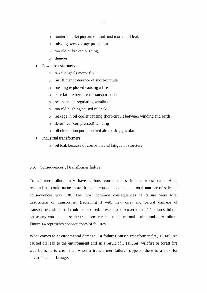
5.5. Consequences of transformer failure
Transformer failure may have serious consequences in the worst case. Here,
respondents could name more than one consequence and the total number of selected
consequences was 138. The most common consequences of failure were total
destruction of transformer (replacing it with new one) and partial damage of
transformer, which still could be repaired. It was also discovered that 17 failures did not
cause any consequences; the transformer remained functional during and after failure.
Figure 14 represents consequences of failures.
What comes to environmental damage, 14 failures caused transformer fire, 15 failures
caused oil leak to the environment and as a result of 3 failures, wildfire or forest fire
was born. It is clear that when a transformer failure happens, there is a risk for
environmental damage.
37
Figure 14. Consequences of transformer failures.
On distribution transformers, the most frequent consequence of failure is the total
destruction of the transformer. Power transformers and industrial transformers are
usually only partially damaged and are thus repairable.
The category “Other” includes consequences as follows:
Distribution transformers
o zero conductor fault to customers
o load moved to other transformer during transformer repair
o 20 kV line switched off because of short-circuit
o transformer change
o on industrial plant, washing water of process got contacted on live parts
Power transformers
o urgent basic maintenance
o load moved to other transformer during transformer change
o damage to LV conductor
38
o replacement of windings
o replacement of all parts except tank and LV bushings
o replacing transformer with spare one
Industrial transformers
o transformer was scrapped and replaced with new one
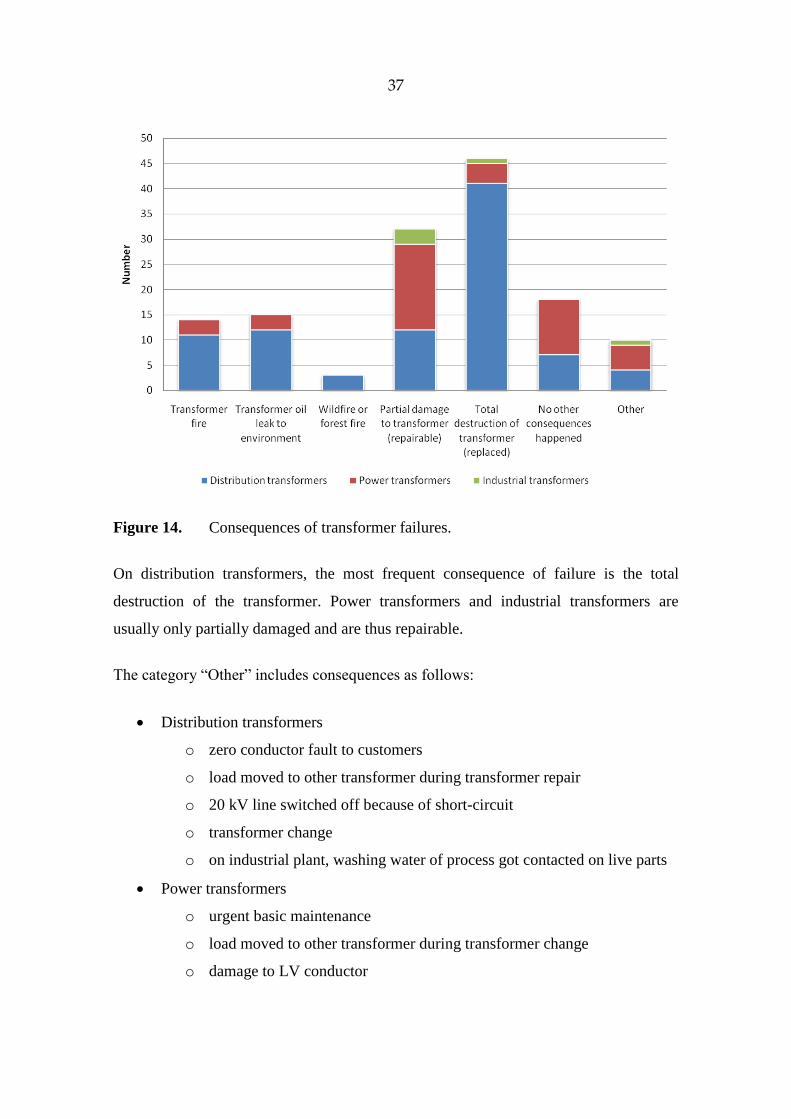
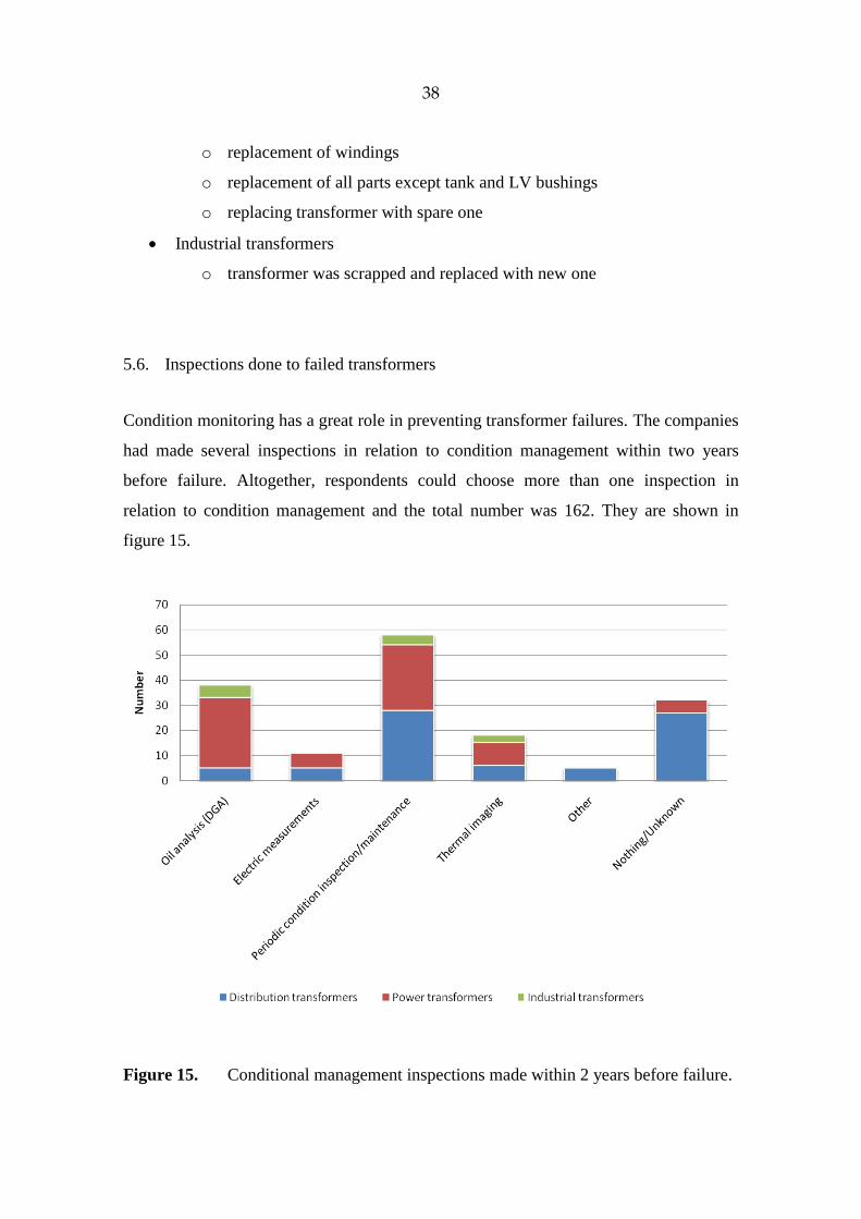
5.6. Inspections done to failed transformers
Condition monitoring has a great role in preventing transformer failures. The companies
had made several inspections in relation to condition management within two years
before failure. Altogether, respondents could choose more than one inspection in
relation to condition management and the total number was 162. They are shown in
figure 15.
Figure 15. Conditional management inspections made within 2 years before failure.
39
It is important to notice that 32 transformers that failed had no condition assessment of
any kind or it was not known. If we want to reduce the risk of failure, some sort of
condition monitoring system should be used. Periodic condition inspection or
maintenance and oil analysis were the most used condition assessment techniques.
Inspections related to condition management were made in different ways depending on
the transformer type. Oil analysis was made mostly on power transformers. Also in 27
distribution transformer failures, condition monitoring was not arranged or it was
unknown.
The category “Other” on distribution transformers includes:
visual inspection of transformer
transformer was already waiting to be replaced due to calculated rate of
overloading
5.7. Methods that may have prevented the failure
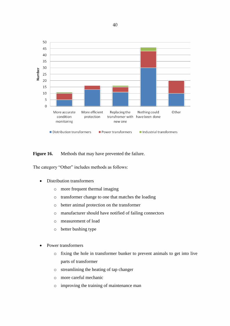
When it comes to means that may have prevented the failure, the leading answer was
“nothing”. From all 109 answers given, 46 answers said that nothing could have been
done. Also here the respondents could choose more than one method. Figure 16 shows
the distribution of failure preventive means.
As we can see, more efficient protection and more accurate condition monitoring are
also good means in preventing the failures. Some transformers should already have been
replaced before failure.
On all types of transformers, the main answer was that nothing could have been done to
prevent the happened failure.
40
Figure 16. Methods that may have prevented the failure.
The category “Other” includes methods as follows:
Distribution transformers
o more frequent thermal imaging
o transformer change to one that matches the loading
o better animal protection on the transformer
o manufacturer should have notified of failing connectors
o measurement of load
o better bushing type
Power transformers
o fixing the hole in transformer bunker to prevent animals to get into live
parts of transformer
o streamlining the heating of tap changer
o more careful mechanic
o improving the training of maintenance man
41
o other type of bushing
o replacing the transformer coolers several years ago
o online gas analysis
o replacing the bushings with new ones
As seen, there is a lot of work in reducing the column “nothing could have been done”.
But other columns can be reduced with proper condition monitoring and more effective
protection, and in some cases, a transformer that comes to the end of its life should be
replaced before failure happens. This is where condition management plays an
important role.
42
6. CONCLUSIONS
The modern power system needs reliable transformers. When transformer failure
happens, consequences may follow from transformer damage to personal injury in the
worst case. In addition, the environmental risk is great with transformer fire, forest fire
and transformer oil leak, not forgetting the harm caused to power consumers by power
delivery interruption to the transformer’s area. There is always a risk that failure brings
large costs.
The aim of this thesis was to clarify transformer faults, causes of them, their numbers
and consequences. It was discovered that transformer failures do not happen frequently.
Fortunately, severe transformer failures happen even less frequently. The consequences
of failure ranged from possible interruption to transformer fire, oil leak and forest fire.
In addition, transformers were usually partially damaged or totally devastated.
It was also discovered that the most vulnerable component of transformer is the
windings by a percentage of 43 % of out of 105 failures. The three main causes for
failure were voltage peak or voltage surge caused by lightning or switching, winding
failure and insulation failure.
Condition management plays a great role in preventing these failures and minimizing
the severity of the consequences including interruption time. The inquiry showed that
companies do use condition monitoring and other inspections to transformers, including
failed ones. On the other hand, it was shown that in more than 30 failures, condition
management inspections were not made at all. This was mainly related to distribution
transformers, but there were also a couple of power transformers where this happened.
However, the importance of condition management is significant in preventing
transformer failures. In the future, the nature and importance of condition management
as a real-time process grows when decentralized power production grows and power is
transmitted to both directions also in the distribution networks.
43
Further research related to transformer failures could be done by clarifying the condition
monitoring techniques. Research could also be done by examining how a fault is born in
the transformer and finding the means to locate and repair them quickly. Also, the
means to prevent failures caused by voltage peaks could be one challenging topic.
Like said before, transformer failures can and will happen whether we want it or not. If
we can repair or replace the transformer before failure with proper condition
management, the power grid remains stable and savings are made at both grid
companies and power consumers.
44
REFERENCES
ABB Oy (2000). Teknisiä tietoja ja taulukoita. 9th edition. Vaasa. 626 p. ISBN 951-
99366-0-2
ABB Oy (2004). Transformer handbook. Zürich. 212 p.
Aro, Martti & Elovaara, Jarmo & Karttunen, Matti & Nousiainen, Kirsi & Palva,
Veikko (2003). Suurjännitetekniikka. 2nd edition. Jyväskylä: Gummerrus
Kirjapaino Oy. 520 p. ISBN 951-672-320-9
Aura, Lauri & Tonteri, Antti J. (1986). Sähkömiehen käsikirja 2 – sähkökoneet.
Porvoo: WSOY. ISBN 951-0-13479-1
Aura, Lauri & Tonteri, Antti J. (2005). Teoreettinen sähkötekniikka ja sähkökoneiden
perusteet. Helsinki: WSOY. 3rd–5th edition. 441 p. ISBN 951-0-21385-3
Bartley, William (2003a). Failure analysis of transformers [online]. The Hartford
Steam Boiler Inspection & Insurance Co. [cited 18 March 2010]. International
Association of Engineering Insurers. 13 p. Available from World Wide Web:
<URL: http://www.imia.com/downloads/external_papers /EP09_2003.pdf>.
Bartley, William (2003b). Analysis of transformer failures [online]. International
association of Engineering Insurers. 36th annual conference. 12 p. Stockholm
2003. [cited 22 March 2010]. Available from World Wide Web:
<URL:http://www.bplglobal.net/eng/knowledge-center/download.aspx?id=191>
Gill, Paul (2009). Electrical power equipment maintenance and testing. 2nd edition.
Boca Raton: CRC press. 961 p. ISBN 978-1-57444-656-2
Harlow, James H. (2004). Electronic Power Transformer Engineering. Boca Raton:
CRC press. ISBN 0-8493-1704-5
Korpinen, Leena (1998). Sähkövoimatekniikkaopus-study handout [online]. Tampere
University of Technology. [cited 8 February 2010]. Available from World Wide
Web: <URL:http://www.leenakorpinen.fi/node/158>.
Mirzai, M. & Gholami, A. & Aminifar, F. (2006). Failure analysis and reliability
calculation for power transformers. Journal of electrical systems. Volume 2,
Issue 1. 1-12 p.
45
Ravindranath, B. & Chander, M. (2005). Power system protection and switchgear. 2nd
edition. New Delhi: New Age International (P) ltd. ISBN 0-85226-758-4
StepUp coalition. How transformer failures affect you [online]. Safer Transformers,
Envirnomental Protection and Upgraded Performance. [cited 18 May 2010]
Available from World Wide Web: <URL: http://www.safertransformers.org/
affect_you.html
Vasudevan, Krishna & Rao, G. Sridhara & Rao, P. Sasidhara. Electrical machines 1 –
web course [online]. Indian Institute of Technology Madras. [cited 4 March
2010]. Available from World Wide Web: <URL:http://nptel.iitm.ac.in/
courses/IIT-MADRAS/Electrical_Machines_I/index.php>.
Wang, M. & Vandemaar, A.J. & Srivastava, K.D. (2002). Review of condition
assessment of power transformers in service. Electrical insulation magazine,
IEEE, Vol. 18, No. 6. 12-25 p.
Winders, John J. Jr. (2002). Power Transformers – Principles and Applications. New
York: Marcel Dekker. 283 p. ISBN 0-8247-0766-4
46
APPENDICES
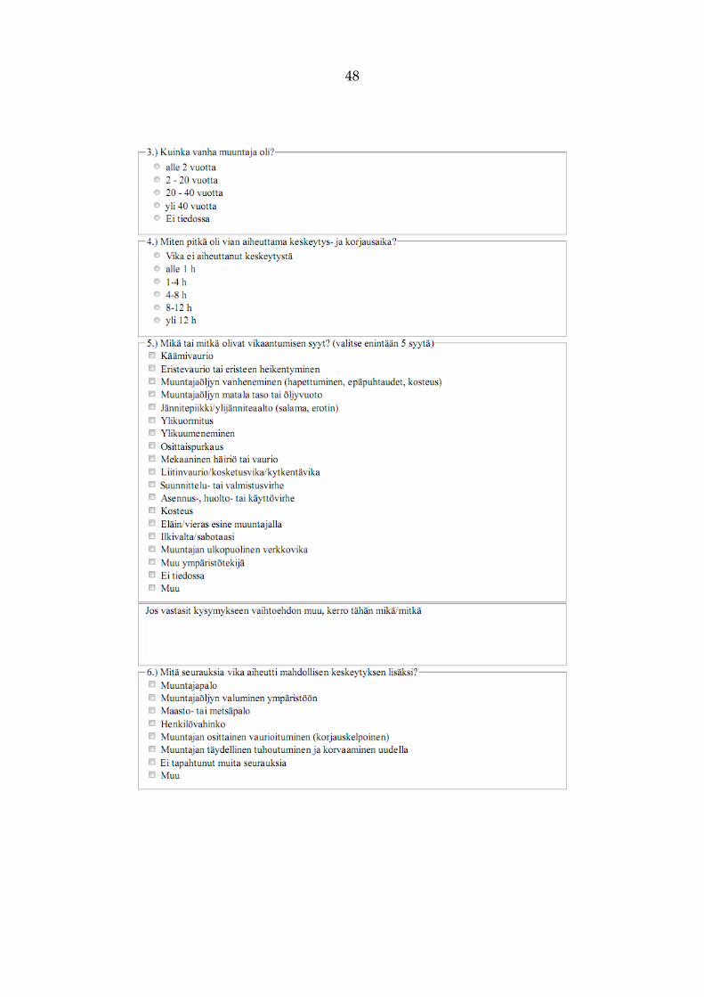
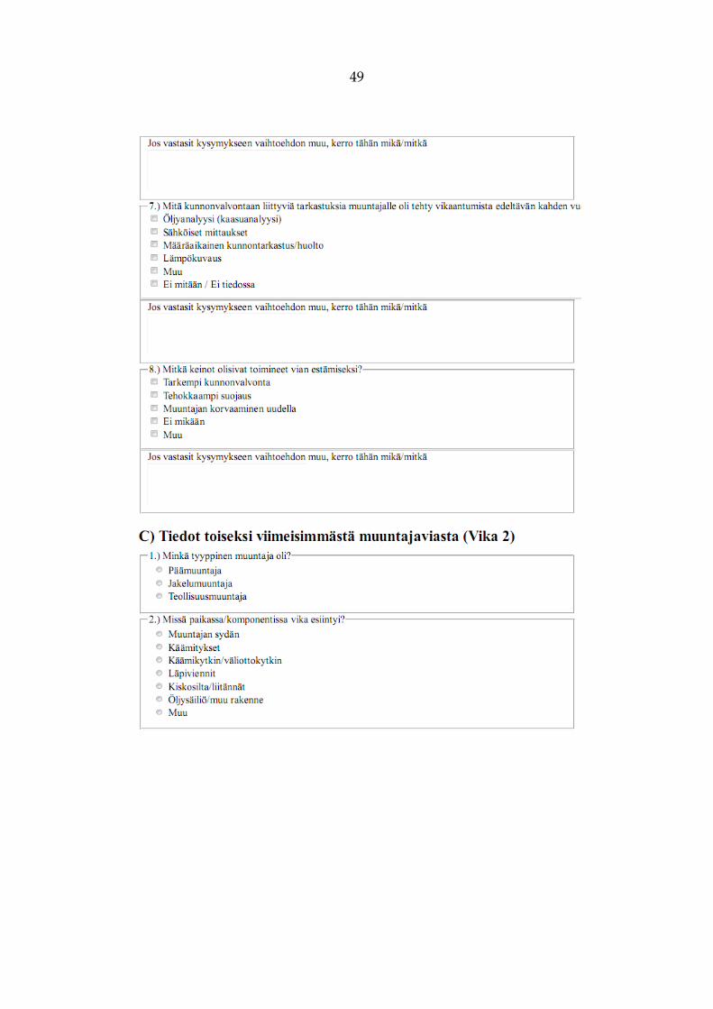
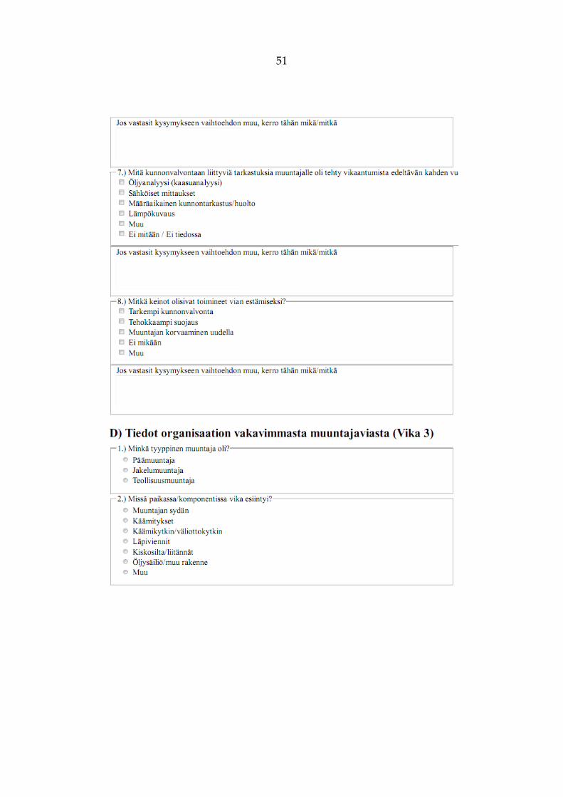
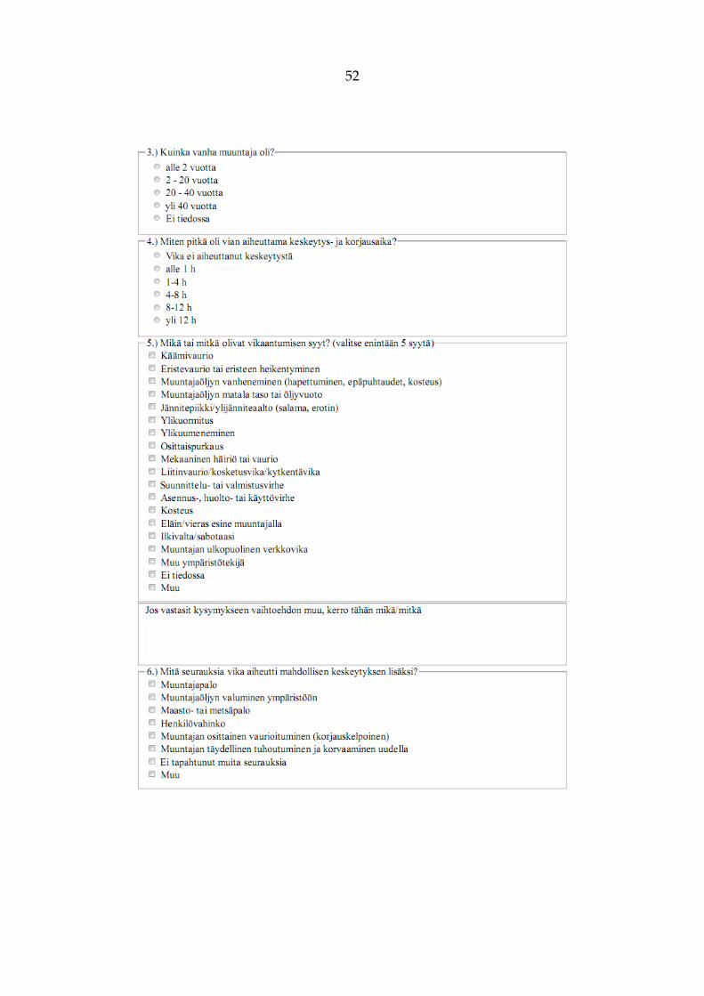
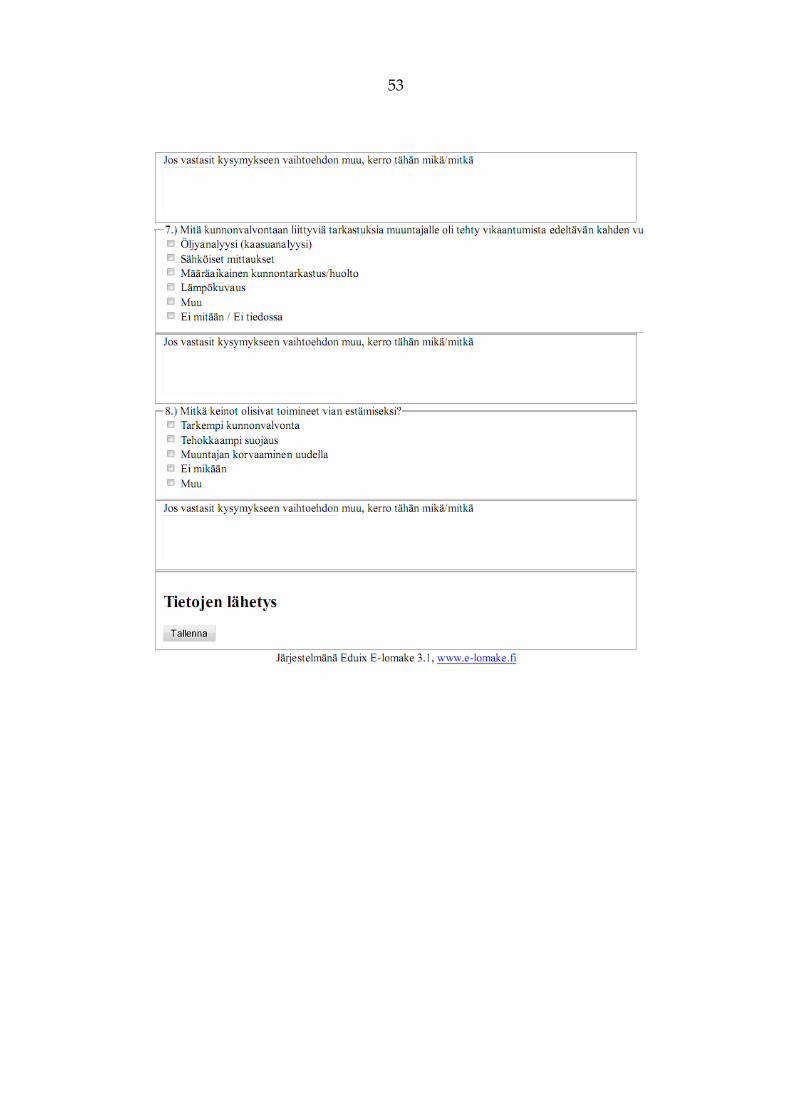
APPENDIX 1. Inquiry form in Finnish
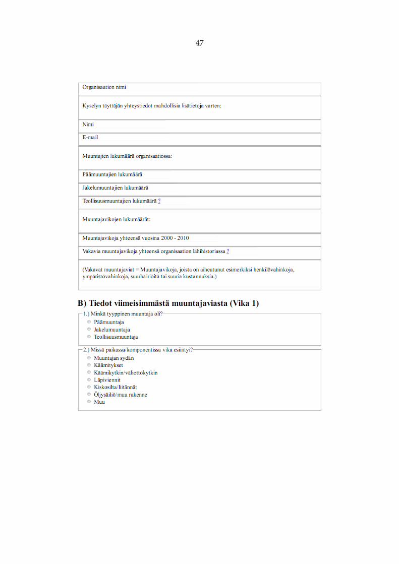
47
48
49

50
51
52
53
54
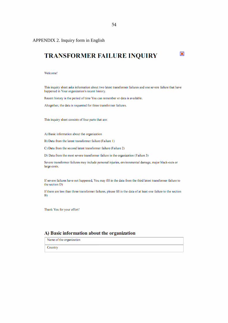
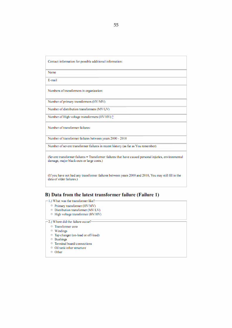
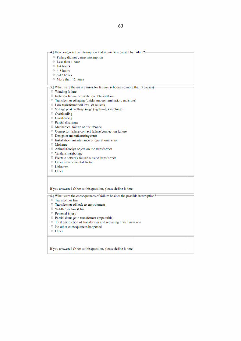
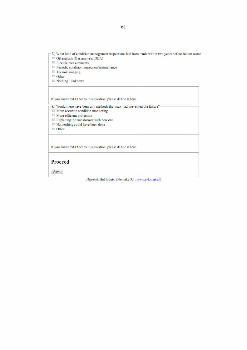
APPENDIX 2. Inquiry form in English
55
56
57
58
59
60
61