Causes of color and designing the color of hard...
12
University of Ljubljana Faculty of Mathematics and Physics
-
Upload
trinhkhanh -
Category
Documents
-
view
224 -
download
1
Transcript of Causes of color and designing the color of hard...

University of LjubljanaFaculty of Mathematics and Physics
Department of Physics
Seminar - 1. year, II. Stage
Causes of color and
designing the color of hard coatings
Author: Nastja Poljan²ek
Mentor: dr. asst. prof. Miha �ekada
Comentor: dr. Peter Panjan
Ljubljana, May 2015
Abstract
Several mechanisms of color creation are described in this seminar. Color is consequence of photon-electroninteraction, some mechanisms can also be described with geometrical optics. In the second part of seminar, designingthe color of hard coatings is presented. There are two mechanisms that cause color of coatings. Intrinsic colors andcoloring trough interference e�ect are presented. CIE 1931 color system is brie�y described.

Contents
1 Introduction 3
2 Causes of colors 32.1 Electron excitation in free atoms and ions, vibrational transitions in
molecules . . . . . . . . . . . . . . . . . . . . . . . . . . . . . . . . . . . . . . 32.2 Electric �eld in�uence in crystals . . . . . . . . . . . . . . . . . . . . . . . . 42.3 Molecular orbit transitions . . . . . . . . . . . . . . . . . . . . . . . . . . . . 42.4 Colors of metals and semiconductors . . . . . . . . . . . . . . . . . . . . . . 42.5 Optical phenomena (refraction, di�raction and interference) . . . . . . . . 5
3 Designing the color of hard coatings 53.1 Intrinsic colors . . . . . . . . . . . . . . . . . . . . . . . . . . . . . . . . . . . 53.2 Interference-based colors . . . . . . . . . . . . . . . . . . . . . . . . . . . . . 6
3.2.1 AlTiN coatings . . . . . . . . . . . . . . . . . . . . . . . . . . . . . . . 73.2.2 Optical constants . . . . . . . . . . . . . . . . . . . . . . . . . . . . . 83.2.3 Color quanti�cation of the samples . . . . . . . . . . . . . . . . . . . 103.2.4 Variation of the color with the angle of view . . . . . . . . . . . . . 10
4 Conclusion 12
5 References 12
.
2
1 Introduction
In my seminar I will present the mechanisms of color creation. Speci�c mechanisms, which are used in sputterdeposition of hard coatings [1 − 2], will be presented in detail. These coatings have a nice look and posses greatproperties such as hardness, wear and thermochemical resistance. They must not tarnish, chip, fade or corrode. Coloris important from decorative aspect, but it can also convey the quality characteristics of the product by creating aunique look on the market. Of course, the importance of well-de�ned color from a decorative point of view is surpassedby other more important technological properties. Hard coatings on various cutting and forming tools wear out withuse. This process can be observed with a naked eye if the coating is colored, so tools can be replaced in time withless interruptions to production lines. To achieve a well-de�ned color in a hard coating, various mechanisms for colorcreation must be known. In my seminar I will present several physical mechanisms of color creation [3− 4]. Speci�cmechanisms of color creation will be presented in detail.
Color is a consequence of interaction between light and free or bound electrons. Such color is called an intrinsiccolor. The other mechanism of coloring in hard coating tehnology is coloring through interference. In that case,thin, fully or partially transparent material is sputtered over material that has intrinsic color. Color of coating isdetermined by a substrate material and also by geometry and composition of a thin �lm. In addition, we must beable to accurately quantify and measure color and color coordinates, which I will describe later. Color creation andhue variation will be presented on a case of AlTiN hard coating sputtered on di�erent substrates.
2 Causes of colors
Color perception is a result of a person's wavelength interpretation. What we consider as colors are in essence di�erentwavelengths of electromagnetic radiation captured by our eyes. The color of an object does not only depend on itsinherent characteristics, which give rise to a color, but also on the color of the light source illuminating it. By default,the light sources discussed in this seminar emit white light, like that of the sun. Mechanisms leading to color creationcan be divided into �ve groups [3]:
a) electron excitation in free atoms and ions, vibrational transitions in molecules,b) electric �eld in�uence in crystals,c) molecular orbit transitions,d) colors of metals and semiconductors,e) optical phenomena (refraction, di�raction and interference).
In all of the above mechanisms there is some sort of electron-photon interaction. In its essence, color is a visualconsequence of material properties. Matter has color if it absorbs wavelengths within the visible spectrum of light.Absorption occurs when electrons are excited from a lower state into one of the higher energy states.
2.1 Electron excitation in free atoms and ions, vibrational transitions in molecules
The �rst mechanism described are the electron transitions in isolated atoms and ions. Atoms and ions can onlyabsorb wavelengths corresponding to discrete energy state transitions. Similarly, when transitioning from a higherenergy state into a lower energy state, the atom emits a photon with the energy matching the energy di�erencebetween both states. Gases, which are composed mostly of free atoms, have highly discrete absorption and emissionspectra. Solid-state matter and liquid matter spectra are continuous. Idealized matter, which absorbs and emitsevery wavelength, is often called a black body. Emission spectrum of a black body depends only on its temperature.Increasing the temperature excites the atoms inside the black body, the result is a black body emission spectrum.When the atoms bond into molecules, new states of excitation occur, such as vibrations and rotations. Absorption ofspeci�c wavelengths is governed by di�erent vibrational and rotational states of the molecule. In the case of a water
3

molecule, the latter absorbs wavelengths predominantly in the red part of the visible spectrum. As a result, waterand ice appear with a bluish hue.
2.2 Electric �eld in�uence in crystals
In the structure of transition metals (for instance Fe, Cr, Cu), a set of unusual electronic states can occur. The innershells of transition metals are only partly occupied, so they can capture free electrons with excitation states insidethe visible spectrum. In the case of ruby and emerald, chromium atoms which replace aluminium atoms inside thebasic molecule, set the visible color. Ruby is mostly made of aluminium oxide. A small percentage of aluminium ionsis replaced by chromium ions. Every chromium ion has three unpaired electrons. The energy of these electrons isdetermined by an electric �eld surrounding them. Electric �eld strength and symmetry are determined by local ions.In ruby, every aluminium or chromium ion resides inside an octahedral cell made of oxygen ions. Oxygen ions in�uencethe excited states of unpaired electrons, so the states are set in the visible parts of the light spectrum, namely violetand yellow-green parts. White light passing through the ruby is therefore absorbed in those regions, so ruby appearsred.
Chromium ions inside emerald are set in di�erent structure, so their unpaired electrons occupy di�erent excitedstates than inside ruby. As a consequence, emerald appears green.
2.3 Molecular orbit transitions
Chemical bond can be formed by pairing of two valence electrons belonging to two atoms. Energy required for anexcitation of such a bound state is usually high; if excited by a photon, the latter would have to originate from theultraviolet region of light spectrum. Such an assumption would be correct only in the case of an electron pair beingbound on the two atoms. Many times, the electron pair is mobile. It can travel along the molecule or molecularorbitals. In such a case, the pair is weakly bound to the atoms, so the excitation energy is lower than in the case of abound pair. One of the coloring mechanisms is charge transfer between two ions. This is the case in a blue sapphire,which is mostly made of aluminium oxide but with added impurities, iron and titanium. In the lowest state, the ironvalence is 2+ while the titanium valence is 4+. If the energy of 2 eV is added, the electron from the iron atom transfersto the titanium atom. The result is an excited state. Such electron transitions constitute a wide absorption band,spanning from yellow to red. Sapphire therefore appears blue.
2.4 Colors of metals and semiconductors
Electrons inside metals and semiconductors are released entirely from attachments to particular atoms or ions andcan move freely throughout a macroscopic volume. The electron density inside a semiconductor in in the order of1023/cm3, so the optical properties of such materials are considerably di�erent from crystals. In metals, all valenceelectrons are equivalent, so they can freely exchange positions. Quantum mechanics forbids those electrons to havethe same energy. At the absolute zero, all the states below Fermi level are occupied, while none are occupied aboveit. If we introduce energy into the system, we can excite electrons to the states above the Fermi level. Metals have analmost continuous spectrum of excited states so they can absorb light with almost any wavelength. Most materialsappear black if they absorb light of all wavelengths. This is not the case with metals. Electrons in metals are excitedby absorbing the photon energy. After the excitation occurs, electrons relax very quickly. Because of these very fasttransitions it appears that metals re�ect light instead of absorbing it. Di�erent surface colors are due to a di�erentnumber of states above the Fermi level in di�erent metals.
Semiconductors also have a continuous band of excited states. On average, one bond is made of four electrons.This is the case in silicon, germanium and DLC (Diamond Like Carbon). The valence band is full, while conduction
4

band is empty. The color of semiconductors depends on the width of their energy gaps. If the band energy gap issmaller than the energy of incident light, the semiconductor has a metallic appearance. When the photon emission isunsuccessful, the semiconductor appears black. If the energy gap is large enough that neither absorption nor emissionoccur, then the material appears colorless. This is a case in diamond. Energy gaps can also lay within the visible partof light spectrum. Semiconductors with large energy gaps can be made to appear colored by doping with impurities.Such impurities can act as electron absorbers or emitters. In both cases, new states between valence and conductionband can form within the energy gap.
2.5 Optical phenomena (refraction, di�raction and interference)
In this section, coloring mechanisms originating from the properties of lightwaves are described.
Di�raction becomes important when the dimensions of obstacles are comparable to the wavelength. At thismechanism the magnitude of the e�ect depends on wavelength of light. Light scatters on small particles and thiscauses a color. Lord Rayleigh showed that incident light is related to the scattered light: Is
I0= const.λ−4 , where Is is
the scattered light, I0 is the incident light and λ is the wavelength of light. We can see, that blue color scatters fourtimes as much as red color. That is the reason why the sky appears blue.
Refraction occurs when light transits from one medium into the optically denser medium or vice versa. Whenlight passes from one medium to another its speed changes. Speed in every material is determined by the interactionof the electromagnetic �eld of the radiation with the electric charges of electrons. For better understanding we canimagine the light ray as a series of plane wave fronts. When one front strikes the surface of the material obliquely, oneedge enters the material and slows down, before the other edge reaches the surface. This results in a change of thedirection when leaving the material. The magnitude of the change depends on the angle at which a light ray reachesthe surface and on the ratio of the speed of light in both materials. This ratio is de�ned as refractive index and is notthe same for all wavelengths. That is why refraction gives a color. Di�erent wavelengths experience di�erent degreesof refraction. We can observe this phenomenon when light passes through a glass prism.
Interference describes the occurrence of visible light patterns resulting from adding (superimposing) two waves ata point. The resulting amplitude is a sum of the amplitudes of both waves. In-phase amplitudes result in constructiveinterference, while waves with the phase di�erence of π result in destructive interference. An example of interferencecan be demonstrated on a case of thin oil �lm on water. Because the �lm is equally thick everywhere, we can seedi�erent wavelengths constructively added at di�erent angles, so the �lm appears rainbow-like.
3 Designing the color of hard coatings
From all the mechanisms described above, only a few can be used in making colored sputtered hard coatings. Protectivecoatings must have high hardness and must be heat and corrosion resistant. Various tribological properties and colors ofcoatings can be achieved by di�erent material combinations. The process of achieving intrinsic coloring and interferencebased colors will be described next.
3.1 Intrinsic colors
In most cases of thin �lm, the produced color is intrinsic. Mechanism of color creation is the same, as described inchapters 2.3 and 2.4.
When the hard coating is TiN, the color appears gold. With changing the nitrogen concentration we can vary thecolor in small portion of color space between metalic gray to gold or even brown. When we incorporate Al, the crystalstructure produces colors of gray, silver or violet depending on Ti and Al ratio.
5
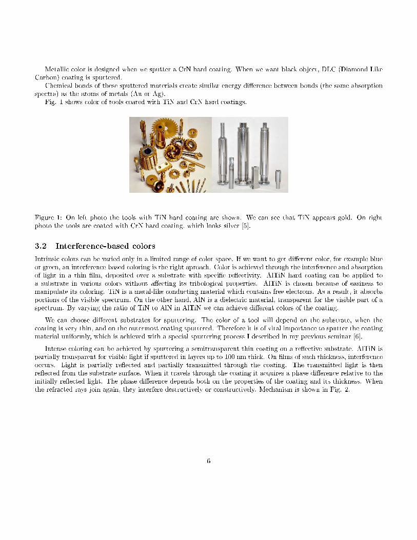
Metallic color is designed when we sputter a CrN hard coating. When we want black object, DLC (Diamond LikeCarbon) coating is sputtered.
Chemical bonds of these sputtered materials create similar energy di�erence between bonds (the same absorptionspectra) as the atoms of metals (Au or Ag).
Fig. 1 shows color of tools coated with TiN and CrN hard coatings.
Figure 1: On left photo the tools with TiN hard coating are shown. We can see that TiN appears gold. On rightphoto the tools are coated with CrN hard coating, which looks silver [5].
3.2 Interference-based colors
Intrinsic colors can be varied only in a limited range of color space. If we want to get di�erent color, for example blueor green, an interference-based coloring is the right aproach. Color is achieved through the interference and absorptionof light in a thin �lm, deposited over a substrate with speci�c re�ectivity. AlTiN hard coating can be applied toa substrate in various colors without a�ecting its tribological properties. AlTiN is chosen because of easiness tomanipulate its coloring. TiN is a metal-like conducting material which contains free electrons. As a result, it absorbsportions of the visible spectrum. On the other hand, AlN is a dielectric material, transparent for the visible part of aspectrum. By varying the ratio of TiN to AlN in AlTiN we can achieve di�erent colors of the coating.
We can choose di�erent substrates for sputtering. The color of a tool will depend on the substrate, when thecoating is very thin, and on the outermost coating sputtered. Therefore it is of vital importance to sputter the coatingmaterial uniformly, which is achieved with a special sputtering process I described in my previous seminar [6].
Intense coloring can be achieved by sputtering a semitransparent thin coating on a re�ective substrate. AlTiN ispartially transparent for visible light if sputtered in layers up to 100 nm thick. On �lms of such thickness, interferenceoccurs. Light is partially re�ected and partially transmitted through the coating. The transmitted light is thenre�ected from the substrate surface. When it travels through the coating it acquires a phase di�erence relative to theinitially re�ected light. The phase di�erence depends both on the properties of the coating and its thickness. Whenthe refracted rays join again, they interfere destructively or constructively. Mechanism is shown in Fig. 2.
6

Figure 2: Schematic of the interference e�ect [5].
In the case of AlTiN sputtering process, both the coating and the substrate have similar physical properties.They both absorb light in the visible spectrum and have complex refractive indices. Re�ectance depends both on thesubstrate and the coating refractive indices, and the thickness of the coating. We will examine a few examples laterto learn how to achieve di�erent colors of a coating.
3.2.1 AlTiN coatings
We can examine AlTiN coatings with di�erent thicknesses, sputtered on di�erent substrates. Substrates were silicon,stainless steel and stainless steel pre-coated with TiN. On all the substrates, coatings of various thicknesses have beensputtered. Coating thicknesses were 25, 35, 43, 48 and 55 nanometres. As seen on the Fig. 3, color depends bothon the substrate material and the coating thickness. If we look at the coating with the thickness of 48 nanometres,we can see that it has a blue color when sputtered on a TiN substrate, a violet one on stainless steel substrate anda light-violet when sputtered on a silicon substrate. On the other hand, we can produce the same color on all of thesubstrates by using coatings of di�erent thicknesses. The coating would have to be the thickest when using siliconsubstrate and the thinnest when using stainless steel pre-coated with TiN.
Figure 3: Photograph of TiN, Stainless Steel (SS) and Si substrates, coated by AlTiN of di�erent thicknesses [5].
7

We can measure re�ectance spectra of di�erent samples. With increasing AlTiN coating thickness the re�ectanceminimum shifts to higher wavelengths. Re�ectance minima can be found at di�erent wavelengths for di�erent sub-strates used. Stainless steel and TiN substrates have re�ectance minima at lower wavelengths compared to the siliconsubstrate.
3.2.2 Optical constants
Colors can be objectively and mathematically described in various ways. They are standardized and measurable withdi�erent systems. One way of color presentation is with CIE 1931 color space [7] which can describe most of theviewable colors. In our eyes we have three kinds of cine cells. First are sensitive to short wavelenghths (420-440nm),the second to medium wavelengths (530-540nm) and the third ones to long wavelengths (560-580nm). Any color canthen be presented as linear combination of cine responses:
C(λ) = x(λ)S + y(λ)M + z(λ)L.
Here S stands for short,M for medium, L for long wavelengths and x, y and z are standard observer color matchingfunctions, presented on Fig. 4.
Figure 4: Standard observer matching functions.
Any color can then be presented in 2D color space by normalization. 2D color space is shown on Fig. 5.
8
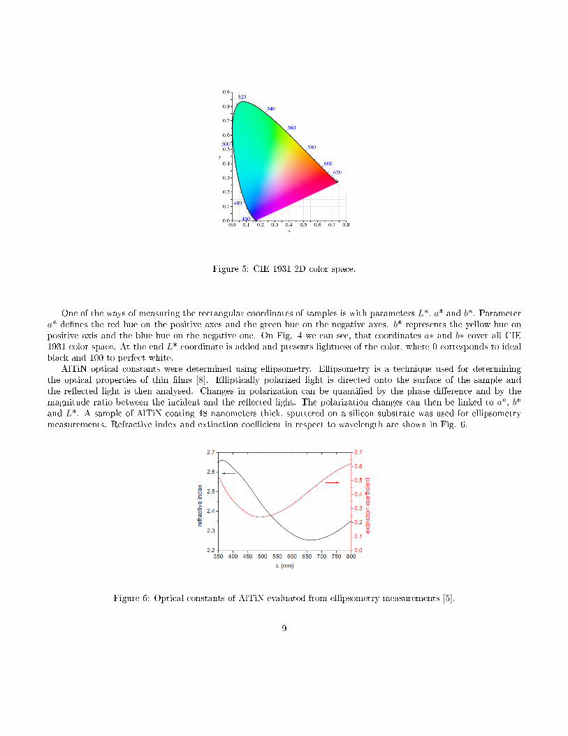
Figure 5: CIE 1931 2D color space.
One of the ways of measuring the rectangular coordinates of samples is with parameters L*, a* and b*. Parametera* de�nes the red hue on the positive axes and the green hue on the negative axes. b* represents the yellow hue onpositive axis and the blue hue on the negative one. On Fig. 4 we can see, that coordinates a∗ and b∗ cover all CIE1931 color space. At the end L* coordinate is added and presents lightness of the color, where 0 corresponds to idealblack and 100 to perfect white.
AlTiN optical constants were determined using ellipsometry. Ellipsometry is a technique used for determiningthe optical properties of thin �lms [8]. Elliptically polarized light is directed onto the surface of the sample andthe re�ected light is then analysed. Changes in polarization can be quanti�ed by the phase di�erence and by themagnitude ratio between the incident and the re�ected light. The polarization changes can then be linked to a*, b*and L*. A sample of AlTiN coating 48 nanometers thick, sputtered on a silicon substrate was used for ellipsometrymeasurements. Refractive index and extinction coe�cient in respect to wavelength are shown in Fig. 6.
Figure 6: Optical constants of AlTiN evaluated from ellipsometry measurements [5].
9

The refractive index quanti�es the phase di�erence between waves, re�ected on di�erent boundaries. The extinctioncoe�cient describes the absorption of light. Typical values of the extinction coe�cients are between 0.25 and 0.6. Wecan see that AlTiN absorbs the least light in the green portion of visible spectrum and absorbs more in the red andblue portions.
3.2.3 Color quanti�cation of the samples
In Fig. 5 we can observe the measured values of L*, a* and b* coordinates. They are shown for each of the substrates.Silicon substrate is shown with a light-blue color, stainless steel substrate is shown with dark blue color while TiN-pre-coated stainless steel is shown with a pink color. We can display a* and b* coordinates separately because theyrepresent hue of the color, while L* does not.
The distance between the origin of coordinate system and the chosen point represents chroma, which is de�ned asc∗ =
√a ∗2 +b∗2. The angle between coordinate a* and vector pointing to the point (a*,b*) is called the hue angle or
the hue of the color: h = arctan(b ∗ /a∗). Saturation is de�ned as s∗ = c ∗ /L∗.
Figure 7: Color coordinates a*,b* and L* measured on di�erent samples [5].
From the plots shown we can see that by varying the substrate material in combination with di�erent coatingthicknesses, we can cover a great part of visible color. Varying the coating thickness gives the variation in color whichis independent of substrate material. Color coordinates change clockwise with increasing coating thickness. TiN pre-coated substrate captures the largest part of the color space. The lowest saturation is observed when silicon substrateis used, while the highest is seen when a TiN pre-coated substrate is used, with a coating thickness of 43 nanometers.By varying AlTiN coating thickness and substrates used, the same hue of color can be achieved. In addition, c* ands* values are di�erent with the same h* values for di�erent substrates used.
3.2.4 Variation of the color with the angle of view
The color viewed depends not only on the coating and substrate properties but also on the total path the light has totravel in a coating, which can be seen also with observing by a naked eye. The path is represented with an angle θ.
10

The larger this observing angle, the larger distance light has to travel inside the coating. Color viewed thus dependson the viewing angle. This e�ect is undesirable, if we want to produce a coating of a single and uniform color.
To observe the color dependence on the viewing angle, L*, a* and b* of the samples at angles between 10° and60° were measured. Measurements are shown on Fig. 8. The samples had an AlTiN coating with thickness of 38nanometers.
Figure 8: Color coordinates with respect to viewing angles [5].
In the case of TiN pre-coated substrate, the color variation can only be seen in a narrow portion of the blue-greencolor space, with lightness being almost constant. Color variation with a silicon substrate is almost the same as withthe TiN pre-coated substrate, while the lightness variation is substantially larger. In a stainless steel substrate, thelargest variation through a portion of color space can be observed. The variation in lightness is also the greatest inthe stainless steel substrate.
To describe the color variation on the viewing angle, color di�erence can be de�ned: ΔE = sqrt(ΔL ∗2 +Δa ∗2+Δb∗2). In Fig. 9 color di�erence in dependence of the viewing angle can be seen for all three di�erent substrates:
Figure 9: Color di�erence in respect to angle of view [5].
11

The lowest color di�erence is observed in the substrate pre-coated with TiN, while the largest belonges to stainlesssteel substrates. By a naked eye we can detect diference in color if the colored objects are placed together if ΔE > 1,while an average human eye can detect ΔE > 5, when colored objects are toghether, but separated with black line.We can detect di�erence in color of two separated objects, when di�erence is ΔE > 20. As seen from the graph, TiNpre-coated substrate is the most suitable for decorative purposes.
4 Conclusion
In this seminar I presented several di�erent mechanisms of color creation. They are a result of interaction between aphoton and an electron. Some of them are described as a consequence of optical phenomena.
It is important to know all the mechanisms of color creation, if we want to manipulate di�erent uniform colors ofobjects which are used in our everyday life. These objects have to possess great properties, such as hardness, corrosion,mechanic and thermochemical resistance. If we want to achieve them, it is not posible to color the objects in anycolor.
PVD decorative coatings that appear in diferent intrinsic colors were described in this seminar. The coloringmechanism based on interference and absorption was described in detail on a case of AlTiN thin �lm sputtered ondi�erent substrates. Detailed optical characterization of these �lms has been presented and also the CIE 1931 colorspace was described in detail.
5 References
.
[1] Panjan P., �ekada M., Za²£ita orodij s trdimi PVD-prevlekami, Institut Joºef Stefan, Ljubljana (2005).[2] Panjan M., Klanj²ek Gunde M., Panjan P.,�ekada M., Designing the color of AlTiN hard coating through
interference e�ect, Surface & Coatings Technology, 245 (2014), 65-72.[3] Nassau K., The Physics and Chemistry of Color: the 15 Mechanisms,The Science of Color, Wiley, (2001).[4] Nassau K., The Causes of Color, Scienti�c American, 243 (1980),106-123.[5] http://www.ijs.si/ctp/ (26.4.2015).[6] Poljan²ek N., Prevleke za za²£ito endoprotez, Seminar, FMF, (2014).[7] CIE, Recommendations in Uniform Color Spaces, Color Di�erence Equations, (1978).[8] http://www.jawoollam.com,(10.4.2015).
12