Catalogue Canalis KTA - Elektro-čelik d.o.o. za ... · Canalis® Catalogue Canalis KTA
205
Prefabricated busbar trunking from 800 to 4000 A Canalis ® Catalogue Canalis KTA << Back
Transcript of Catalogue Canalis KTA - Elektro-čelik d.o.o. za ... · Canalis® Catalogue Canalis KTA
Prefabricated busbar trunking from 800 to 4000 A
Canalis®
CatalogueCanalis KTA
<< Back

3Schneider Electric
Contents
Presentation and description
Panorama of Canalis range K9AE11000/2General K9AE12000/2Run sections K9AE12000/3Disconnectors and run protective devices K9AE12000/4Change of direction sections K9AE12000/5Connection sections K9AE12000/6Connection accessories K9AE12000/12Supports and fi xings K9AE12000/14Tap-off units K9AE13000/2
Catalogue numbers and dimensions
Run components K9AE21010/2Elbow components for changing direction K9AE22010/2Zed components for changing direction K9AE22020/2Canalis interfaces K9AE23000/2Feed units for switchboards and oil immersed transformers K9AE24010/2Feed units for dry-type transformers K9AE24020/2Supports and fi xings K9AE25000/2Tap-off units K9AE26010/2Coupling isolators and protection of the run K9AE26030/2Special products K9AE27000/2
Design guide
Characteristics K9AE39000/2Design guide K9AE31000/2Selection guide K9AE31000/14Degree of protection K9AE32000/2Harmonic currents K9AE33000/2Direct current K9AE34010/2Frequencies K9AE34020/2Measurements and metering K9AE34030/2Fire resistance K9AE35000/2Testing and commissioning procedure K9AE36010/2
Installation guide
Layout advice K9AE41000/2Horizontal distribution K9AE41000/12Rising mains K9AE45000/2Panorama of connection solutions K9AE42000/2Connection to LV switchboards K9AE42000/4Connection to cast resin transformers K9AE43000/2Connection to oil immersed transformers K9AE44000/2
Recommendations
Reception, handling and storage 2Maintenance 2Recycling 3
Introduction
In decentralised distribution, Canalis hits the high note! K9AE01010/3With Canalis, you play all the right notes! K9AE01020/2Canalis, in total harmony with the environment! K9AE01030/2Canalis, fortissimo throughout the range! K9AE01040/2Canalis KT, a display of advantages! K9AE02010/2Canalis KT, everyone to their music! K9AE02020/2Play all the world’s musicwith Canalis! K9AE02030/2With the Canalis tools and services, let us compose your project! K9AE02040/2


PD
2023
82
PD
2023
80
PD
2020
88-1
04
3Schneider Electric
Intr
od
uct
ion
In decentralised distribution, Canalis hits the high note!
Canalis on its second world tourTo better meet your needs, Canalis extends its system solutions.New low and medium power busbar trunking products.Pre-equipped luminaires.Strip lighting.Specially designed cable trays.
A total coordination with theSchneider Electric systemCanalis is now part of a comprehensive offering of Schneider Electric products designed to operate together. This concept covers all low and medium voltage electrical distribution components. The result is an optimised electrical installation with even higher performance through full electrical, mechanical and communication compatibility.With the new Canalis range, you get a complete, tested distribution solution that complies with standards. It is perfectly suited to traditional applications (factories, warehouses, etc.) and to the distribution of electrical power from the incoming transformer on through to all types of loads in offi ces, commercial premises, laboratories, etc.
Canalis KT is changing to provide you with…
… more fl exibility. The adjustable section adapts to the worksite thus making sure you meet deadlines.
bbbbb
b
… ease of connection with the “plug and play” transformer and switchboard connections.
… more assistance. Our teams will assist you throughout your project.
b
b
Canalis moves forward without changing the way you workThe new Canalis range is fully compatible with the existing range.An existing installation can be upgraded without any problem.
More than 50,000 km of Canalis busbar trunking has been sold around the world.
K9AF01010
K9AE01020
PD
2020
43P
D20
2044
PD
2021
55
2 Schneider Electric
Intr
od
uct
ion
With Canalis, you play all the right notes!
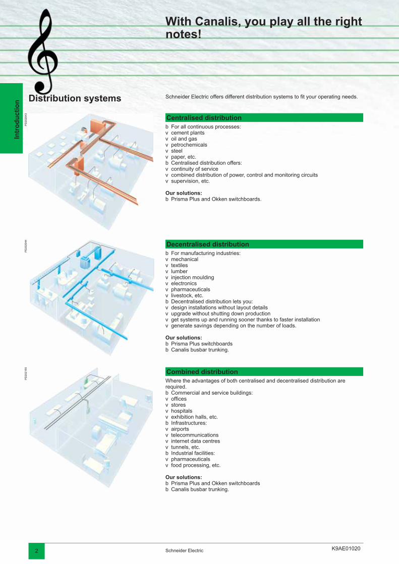
Distribution systems Schneider Electric offers different distribution systems to fi t your operating needs.
Centralised distributionFor all continuous processes:cement plantsoil and gaspetrochemicalssteelpaper, etc.Centralised distribution offers:continuity of servicecombined distribution of power, control and monitoring circuitssupervision, etc.
Our solutions:Prisma Plus and Okken switchboards.
bvvvvvbvvv
b
Decentralised distributionFor manufacturing industries:mechanicaltextileslumberinjection mouldingelectronicspharmaceuticalslivestock, etc.Decentralised distribution lets you:design installations without layout detailsupgrade without shutting down productionget systems up and running sooner thanks to faster installationgenerate savings depending on the number of loads.
Our solutions:Prisma Plus switchboardsCanalis busbar trunking.
bvvvvvvvbvvvv
bb
Combined distributionWhere the advantages of both centralised and decentralised distribution are required.
Commercial and service buildings:offi cesstoreshospitalsexhibition halls, etc.Infrastructures:airportstelecommunicationsinternet data centrestunnels, etc.Industrial facilities:pharmaceuticalsfood processing, etc.
Our solutions:Prisma Plus and Okken switchboardsCanalis busbar trunking.
bvvvvbvvvvbvv
bb
K9AE01020
PD
2023
83P
D20
2427
3Schneider Electric
Intr
od
uct
ion
With Canalis, you play all the right notes!
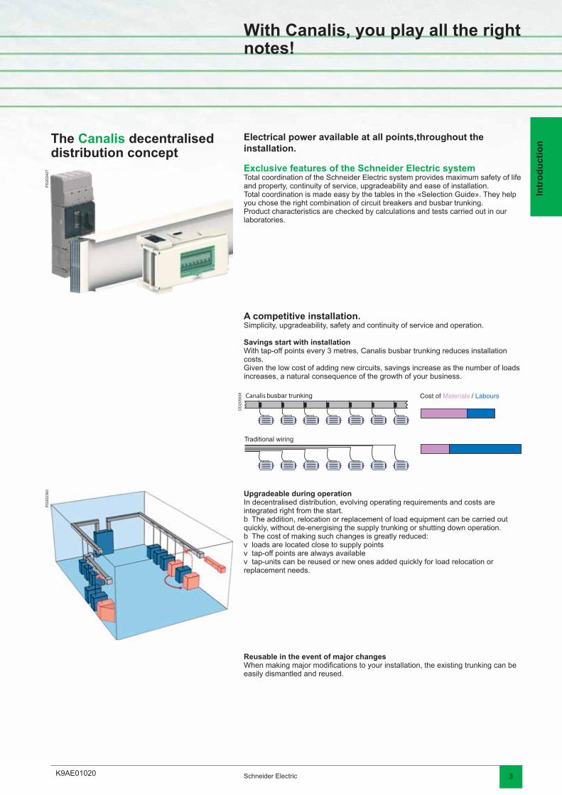
The Canalis decentralised distribution concept
Electrical power available at all points,throughout the installation.
Exclusive features of the Schneider Electric systemTotal coordination of the Schneider Electric system provides maximum safety of life and property, continuity of service, upgradeability and ease of installation.Total coordination is made easy by the tables in the «Selection Guide». They help you chose the right combination of circuit breakers and busbar trunking.Product characteristics are checked by calculations and tests carried out in our laboratories.
A competitive installation.Simplicity, upgradeability, safety and continuity of service and operation.
Savings start with installationWith tap-off points every 3 metres, Canalis busbar trunking reduces installation costs.Given the low cost of adding new circuits, savings increase as the number of loads increases, a natural consequence of the growth of your business.
Upgradeable during operationIn decentralised distribution, evolving operating requirements and costs are integrated right from the start.
The addition, relocation or replacement of load equipment can be carried out quickly, without de-energising the supply trunking or shutting down operation.
The cost of making such changes is greatly reduced:loads are located close to supply pointstap-off points are always availabletap-units can be reused or new ones added quickly for load relocation or
replacement needs.
b
bvvv
Reusable in the event of major changesWhen making major modifi cations to your installation, the existing trunking can be easily dismantled and reused.
DD
2056
58

K9AF01030
DD
2056
75D
D20
5674
2 Schneider Electric
Intr
od
uct
ion
Canalis, in total harmony with the environment!
Safety of life and property With Canalis, no risk in case of fi reThe busbar trunking has a low combustible load. Its construction uses very little consumable material and is halogen free.In the event of a fi re, the busbar trunking does not emit any gas or toxic smoke.
An inherent fi re barrier, the busbar trunking helps prevent the propagation of a fi re through partition walls and fl oors for a duration of 2 hours.
Halogen-sensitive applicationsPublic buildings (infrastructures, hospitals, schools, etc.).Buildings with evacuation diffi culties (high-rises, ships, etc.) and service-activity
buildings.Sensitive processes (production of electronic components, etc.).
Canalis contains no PVCsWhen PVCs burn, they produce large amounts of smoke that can be a serious safety hazard.
Reduced visibility:risk of paniccomplicates rescue workSmoke toxicity:hydrogen chloride gas (highly toxic)carbon monoxide (danger of asphyxiation).
bb
b
bvvbvv
Canalis reduces the risk of exposure to electromagnetic fi eldsAccording to the WHO (World Health Organisation), exposure to electromagnetic fi elds can be a health hazard starting at levels as low as 0.2 micro-Teslas and could represent a long-term risk of cancer. Some countries have created standards that stipulate limits (e.g. 0.2 µT at 1 metre in Sweden).
All electrical conductors generate magnetic fi elds proportional to the distance between them. The design of Canalis busbar trunking with tightly spaced conductors in a metal enclosure helps to considerably reduce radiated electromagnetic fi elds.
The electromagnetic fi eld characteristics of Canalis busbar trunking are well-defi ned and measurements show that they are far below potentially dangerous levels.You will fi nd the magnetic induction values of our products on the “Characteristics” pages.
Example:Consequences of a fi re in a 100 m2 offi ce with electrical distribution by cables.200 kg of cables (i.e. 20 kg of PVC) produces:
4400 m3 of smoke7.5 m3 of hydrochloric acid3.7 kg of corroded steel.
bbb
Health
K9AF01030
DD
2056
73
3Schneider Electric
Intr
od
uct
ion
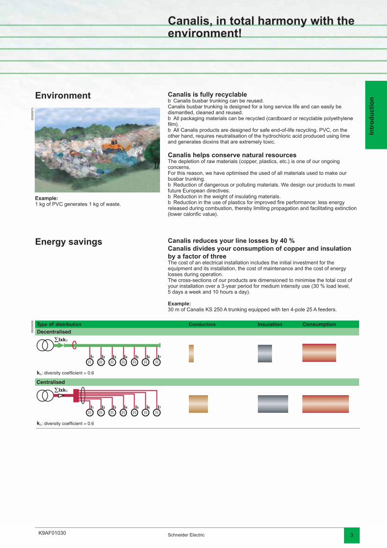
Canalis, in total harmony with the environment!
Environment Canalis is fully recyclableCanalis busbar trunking can be reused.
Canalis busbar trunking is designed for a long service life and can easily be dismantled, cleaned and reused.
All packaging materials can be recycled (cardboard or recyclable polyethylene fi lm).
All Canalis products are designed for safe end-of-life recycling. PVC, on the other hand, requires neutralisation of the hydrochloric acid produced using lime and generates dioxins that are extremely toxic.
Canalis helps conserve natural resourcesThe depletion of raw materials (copper, plastics, etc.) is one of our ongoing concerns.For this reason, we have optimised the used of all materials used to make our busbar trunking.
Reduction of dangerous or polluting materials. We design our products to meet future European directives.
Reduction in the weight of insulating materials.Reduction in the use of plastics for improved fi re performance: less energy
released during combustion, thereby limiting propagation and facilitating extinction (lower calorifi c value).
b
b
b
b
bb
Example:1 kg of PVC generates 1 kg of waste.
Energy savings Canalis reduces your line losses by 40 %Canalis divides your consumption of copper and insulation by a factor of threeThe cost of an electrical installation includes the initial investment for the equipment and its installation, the cost of maintenance and the cost of energy losses during operation.The cross-sections of our products are dimensioned to minimise the total cost of your installation over a 3-year period for medium intensity use (30 % load level,5 days a week and 10 hours a day).
Example:30 m of Canalis KS 250 A trunking equipped with ten 4-pole 25 A feeders.
DD
2056
56
K9AE01040
PD
2023
84
2 Schneider Electric
Intr
od
uct
ion
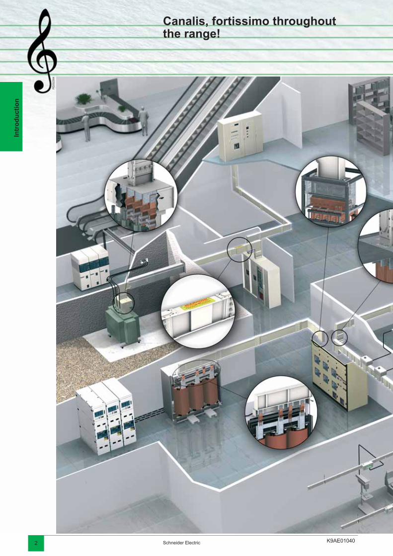
Canalis, fortissimo throughoutthe range!
K9AE01040 3Schneider Electric
Intr
od
uct
ion
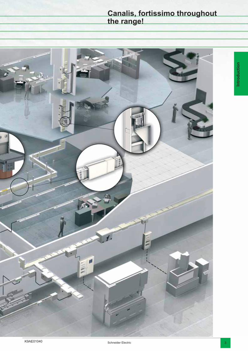
Canalis, fortissimo throughoutthe range!
K9AE02010
PD
2023
85D
D20
2860
2 Schneider Electric
Intr
od
uct
ion
Canalis KT, a display of advantages!
The compact size of Canalis KT means it takes up very little space in the building:
used as a rising main, it takes up only a minimum of space,used for horizontal distribution, it fi ts easily into the building’s structure (false
fl oors, false ceilings, service shafts, etc).
Changes in direction have been designed to optimise the space taken up, contrary to an equivalent installation using cables which requires large bending radii.
Tap-off units, complete with protective devices, are fi tted along the entire length of the busbar trunking thus reducing the fl oor area taken up by the electrical distribution switchboards.
b
vv
b
b
A compact solution
A simple and economical system
The design study is easy to perform as it does not require a detailed layout of each load. Equipment choice is pre-determined and optimised.
Installing the busbar trunking requires 2 or 3 people only, for a time equivalent to that for installing cableways. The time normally needed for laying cables is therefore saved.
Connection to the MV / LV substation is made using a quick fi tting joint block. The tap-off units can be prepared in the workshop thus reducing on-site time. Their connection to the busbar trunking is done in a single plugging-on operation.
Installing busbar trunking lengths can be done as and when building work progresses, thus optimising on-site work and allowing possible unexpected events to be anticipated in advance.
It is also important to note that busbar trunking is a factory tested solution, meaning the time needed for inspecting connections is reduced (visual inspection of tightening torque).
b
b
b
b
b
K9AE02010
PD
2022
29-6
8P
D20
2386
3Schneider Electric
Intr
od
uct
ionComplete safety Busbar trunking temperature rise and short-circuit withstand are known and
independent of the installation. Coordination of the Schneider Electric system results in complete control of the electrical network.
Installation standards UTE C 15-105 chapter B.6.2 and IEC 60 364 chapter 5.523.6 stipulate that above 4 parallel cables, it is preferable to use busbar trunking. Paralleling many cables leads to uneven distribution of currents and the risk of abnormal temperature rise.
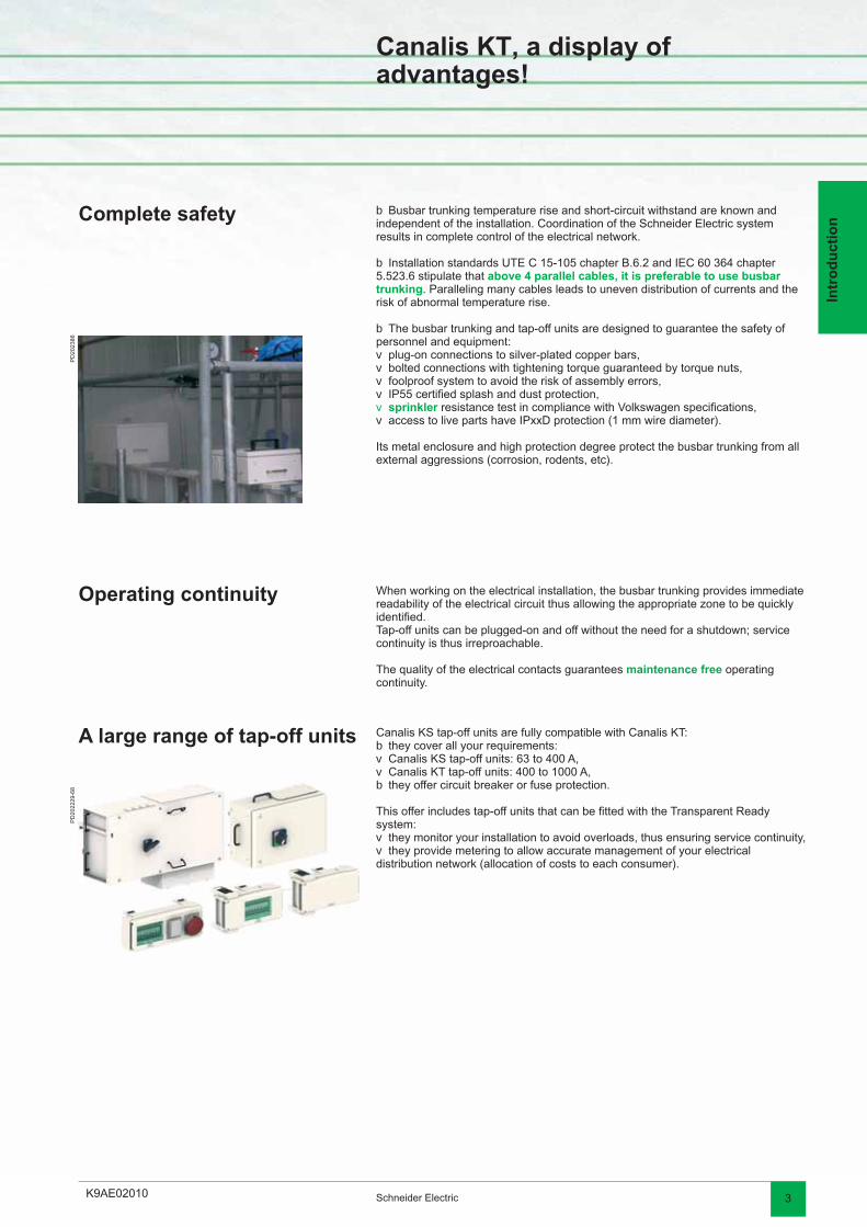
The busbar trunking and tap-off units are designed to guarantee the safety of personnel and equipment:
plug-on connections to silver-plated copper bars,bolted connections with tightening torque guaranteed by torque nuts,foolproof system to avoid the risk of assembly errors,IP55 certifi ed splash and dust protection,sprinkler resistance test in compliance with Volkswagen specifi cations,access to live parts have IPxxD protection (1 mm wire diameter).
Its metal enclosure and high protection degree protect the busbar trunking from all external aggressions (corrosion, rodents, etc).
b
b
b
vvvvvv
Operating continuity When working on the electrical installation, the busbar trunking provides immediate readability of the electrical circuit thus allowing the appropriate zone to be quickly identifi ed.Tap-off units can be plugged-on and off without the need for a shutdown; service continuity is thus irreproachable.
The quality of the electrical contacts guarantees maintenance free operating continuity.
A large range of tap-off units Canalis KS tap-off units are fully compatible with Canalis KT:they cover all your requirements:Canalis KS tap-off units: 63 to 400 A,Canalis KT tap-off units: 400 to 1000 A,they offer circuit breaker or fuse protection.
This offer includes tap-off units that can be fi tted with the Transparent Ready system:
they monitor your installation to avoid overloads, thus ensuring service continuity,they provide metering to allow accurate management of your electrical
distribution network (allocation of costs to each consumer).
bvvb
vv
Canalis KT, a display of advantages!
K9AE02020
PD
2023
91
PD
2023
88
PD
2023
87
PD
2023
89
PD
2023
90
2 Schneider Electric
Intr
od
uct
ion
Canalis KT, everyone to their music!
Key points
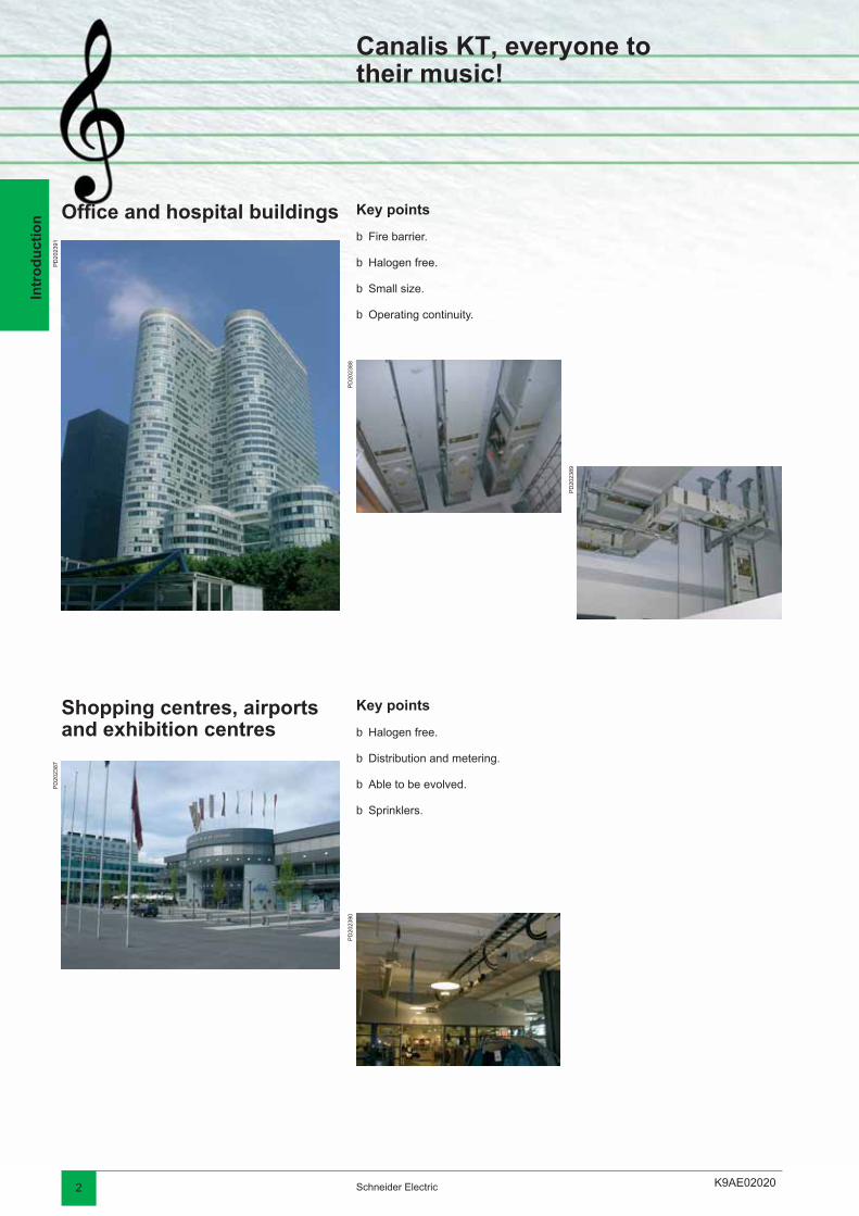
Fire barrier.
Halogen free.
Small size.
Operating continuity.
b
b
b
b
Offi ce and hospital buildings
Key points
Halogen free.
Distribution and metering.
Able to be evolved.
Sprinklers.
b
b
b
b
Shopping centres, airports and exhibition centres

K9AE02020
PD
3950
77-6
8
PD
2023
92
PD
2023
93
1094
05
PD
2023
94
PD
2023
95
3Schneider Electric
Intr
od
uct
ion
Canalis KT, everyone to their music!
Key points
Operating continuity.
Able to be evolved.
Low voltage drops.
Network readability.
b
b
b
b
Car industry andindustrial buildings
Key points
Operating continuity.
High tap-off density.
Able to be evolved.
Network compactness and readability.
b
b
b
b
Internet Data Centers

K9AE020302 Schneider Electric
Intr
od
uct
ion
Play all the world’s musicwith Canalis!
Tertiary
Name Lighting and low current Medium current High current
Country
KDP KBA KBB KN KS KT
Offi ces
PD
2022
44 Air France (headquarters) b b France
Allianz b b Germany
Axa b b France
Chamber of Commerce b b Luxembourg
Commerz Bank b b Germany
Lexel b b b Sweden
Telefónica b b Spain
Trade Center b b Spain
Tour du RDC b b Tunisia
Turning Torso b Sweden
Vodafone b b New Zealand
Internet Data Center
PD
2022
45 Banco Commercial Português b b Portugal
Colt b b France
Digiplex b b Sweden
IBM b b b b Spain, Italy
MCI-Worldcom b b b b Italy, United Kingdom
Hotels and restaurants
PD
2022
46 Hyatt b Tunisia
Mc Donald’s b France
Soldeo Andorra Hotel b b Spain
Hospitals
PD
2022
47 Children Clinic b b Sweden
Brussels University Hospital b Belgium
Derby Hospital b United Kingdom
Oran Hospital b b Algeria
St Joseph Hospital b France
Stockholm Hospital b Sweden
Val de Grâce Hospital b France
Michalon Hospital b b France
Manussia Hospital b Egypt
Supermarkets and hypermarkets
PD
2022
48 Alcampo b b b Spain
Auchan b b b b b b World
B&Q b b b United Kingdom
Carrefour b b b b b b World
Coop b b b Italy
Fnac b b Spain, France
Ikea b b b b b China, Spain, France, Sweden
Mark & Spencer b Belgium, Spain, United Kingdom
Toys’R Us b Spain
K9AE02030 3Schneider Electric
Intr
od
uct
ion
Play all the world’s musicwith Canalis!
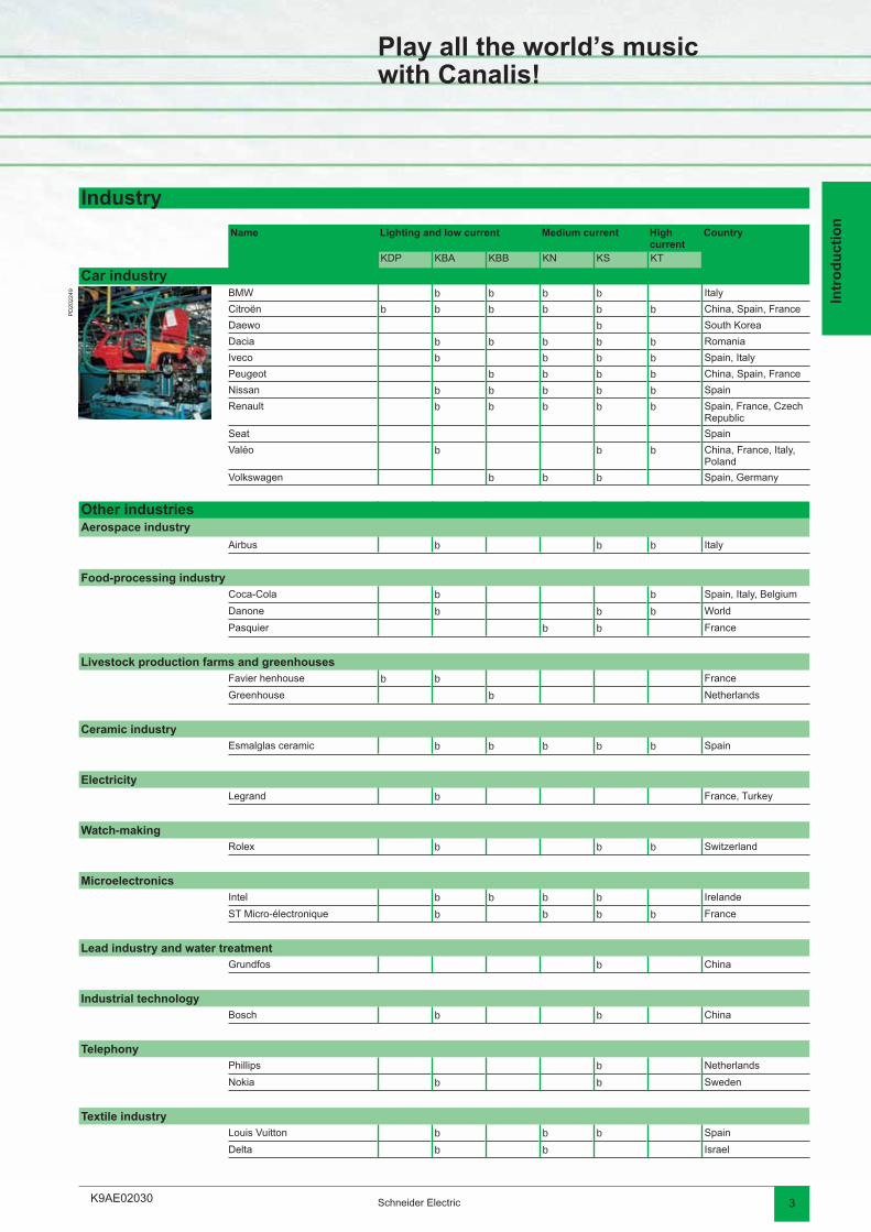
Industry
Name Lighting and low current Medium current High current
Country
KDP KBA KBB KN KS KT
Car industry
PD
2022
49 BMW b b b b Italy
Citroën b b b b b b China, Spain, France
Daewo b South Korea
Dacia b b b b b Romania
Iveco b b b b Spain, Italy
Peugeot b b b b China, Spain, France
Nissan b b b b b Spain
Renault b b b b b Spain, France, Czech Republic
Seat Spain
Valéo b b b China, France, Italy, Poland
Volkswagen b b b Spain, Germany
Other industriesAerospace industry
Airbus b b b Italy
Food-processing industryCoca-Cola b b Spain, Italy, Belgium
Danone b b b World
Pasquier b b France
Livestock production farms and greenhousesFavier henhouse b b France
Greenhouse b Netherlands
Ceramic industryEsmalglas ceramic b b b b b Spain
ElectricityLegrand b France, Turkey
Watch-makingRolex b b b Switzerland
MicroelectronicsIntel b b b b Irelande
ST Micro-électronique b b b b France
Lead industry and water treatmentGrundfos b China
Industrial technologyBosch b b China
TelephonyPhillips b Netherlands
Nokia b b Sweden
Textile industryLouis Vuitton b b b Spain
Delta b b Israel
K9AE020304 Schneider Electric
Intr
od
uct
ion
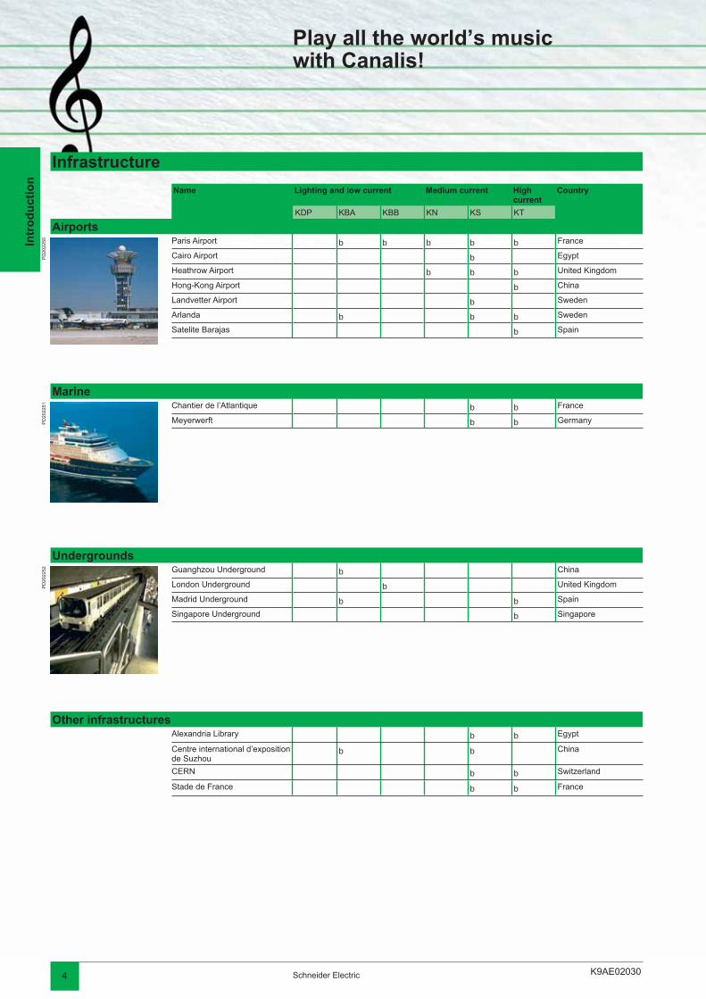
Infrastructure
Name Lighting and low current Medium current High current
Country
KDP KBA KBB KN KS KT
Airports
PD
2022
50 Paris Airport b b b b b France
Cairo Airport b Egypt
Heathrow Airport b b b United Kingdom
Hong-Kong Airport b China
Landvetter Airport b Sweden
Arlanda b b b Sweden
Satelite Barajas b Spain
Marine
PD
2022
51 Chantier de l’Atlantique b b France
Meyerwerft b b Germany
Undergrounds
PD
2022
52 Guanghzou Underground b China
London Underground b United Kingdom
Madrid Underground b b Spain
Singapore Underground b Singapore
Other infrastructuresAlexandria Library b b Egypt
Centre international d’exposition de Suzhou
b b China
CERN b b Switzerland
Stade de France b b France
Play all the world’s musicwith Canalis!

K9AE02030 5Schneider Electric
Intr
od
uct
ion

K9AE020402 Schneider Electric
Intr
od
uct
ion
With the Canalis tools and services, let us compose your project!
Technical fi les The technical fi les have been compiled from completed contracts and provide answers to questions concerning the installation of Canalis busbar trunking in specifi c business sectors.
In data centersReference:ART 3722DESBS001FR
In exhibition centresReference:ART 65946KD0C00CTAFEEN / 65946
In shopping centresReference:Available in your sales offi ce.
In electronics factoriesReference:ART 65944KD0C00CTAFEEN / 65944
In tiles factoriesReference:DEBU005EN
In car plantsReference:Available in your sales offi ce.
In livestock buildingsReference:DESWED105010EN
In greenhousesReference:ART 808260DESWED105013EN
In logistic centresReference:ART 807993DESWED105011EN
In cruise shipsReference:DESWED105014EN
In garagesReference:DESWED103004EN
Find a large range of Cahier Technique publications on the Schneider Electric web site: www.schneider-electric.com.
K9AE02040
PD
2023
96D
D21
0861
3Schneider Electric
Intr
od
uct
ion
With the Canalis tools and services, let us compose your project!
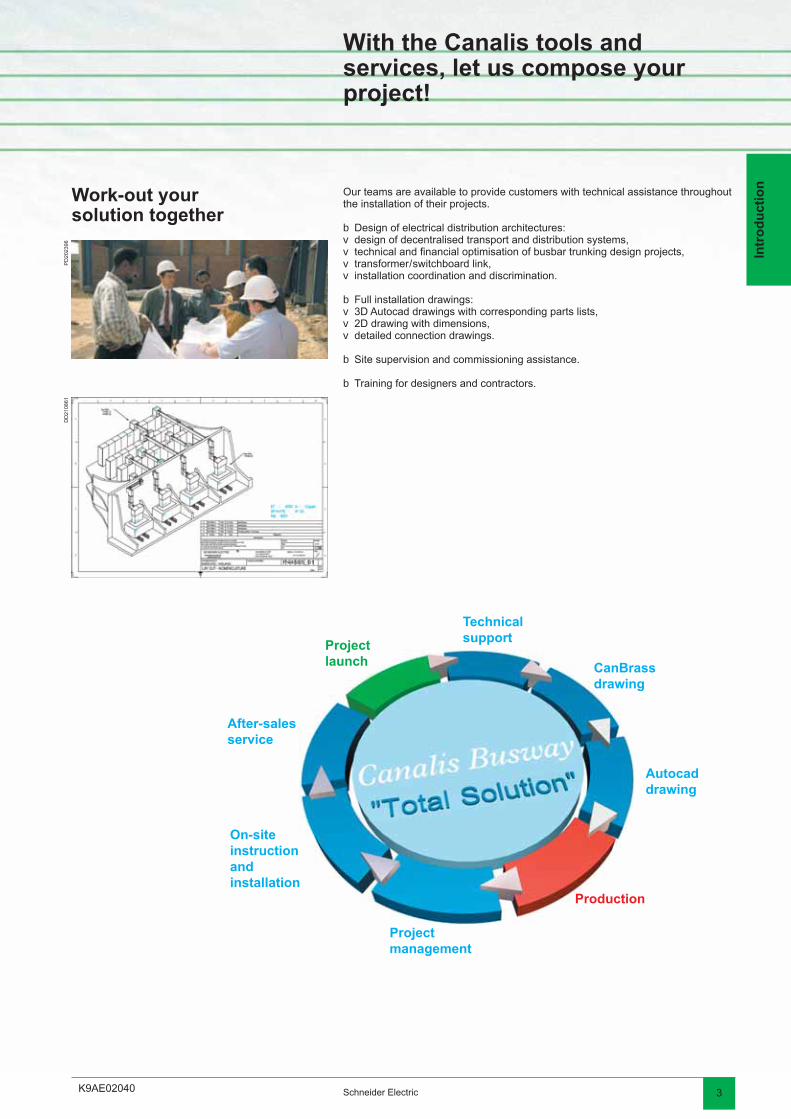
Work-out yoursolution together
Our teams are available to provide customers with technical assistance throughout the installation of their projects.
Design of electrical distribution architectures:design of decentralised transport and distribution systems,technical and fi nancial optimisation of busbar trunking design projects,transformer / switchboard link,installation coordination and discrimination.
Full installation drawings:3D Autocad drawings with corresponding parts lists,2D drawing with dimensions,detailed connection drawings.
Site supervision and commissioning assistance.
Training for designers and contractors.
bvvvv
bvvv
b
b
Project launch
Technical support
CanBrass drawing
Autocad drawing
Production
Project management
On-site instruction and installation
After-sales service
K9AE020404 Schneider Electric
Intr
od
uct
ion
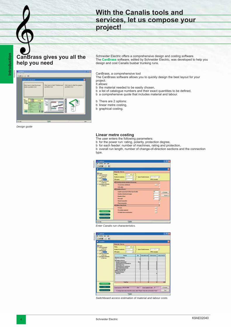
Enter Canalis run characteristics.
With the Canalis tools and services, let us compose your project!
Switchboard access estimation of material and labour costs.
Schneider Electric offers a comprehensive design and costing software.The CanBrass software, edited by Schneider Electric, was developed to help you design and cost Canalis busbar trunking runs.
CanBrass, a comprehensive toolThe CanBrass software allows you to quickly design the best layout for your project.It allows:
the material needed to be easily chosen,a list of catalogue numbers and their exact quantities to be defi ned,a comprehensive quote that includes material and labour.
There are 2 options:linear metre costing,graphical costing.
bbb
bbb
CanBrass gives you all the help you need
Design guide
Linear metre costingThe user enters the following parameters:
for the power run: rating, polarity, protection degree,for each feeder: number of machines, rating and protection,overall run length, number of change-of-direction sections and the connection
type.
bbb
PD
2023
74
PD
2023
75P
D20
2376
K9AE02040 5Schneider Electric
Intr
od
uct
ion
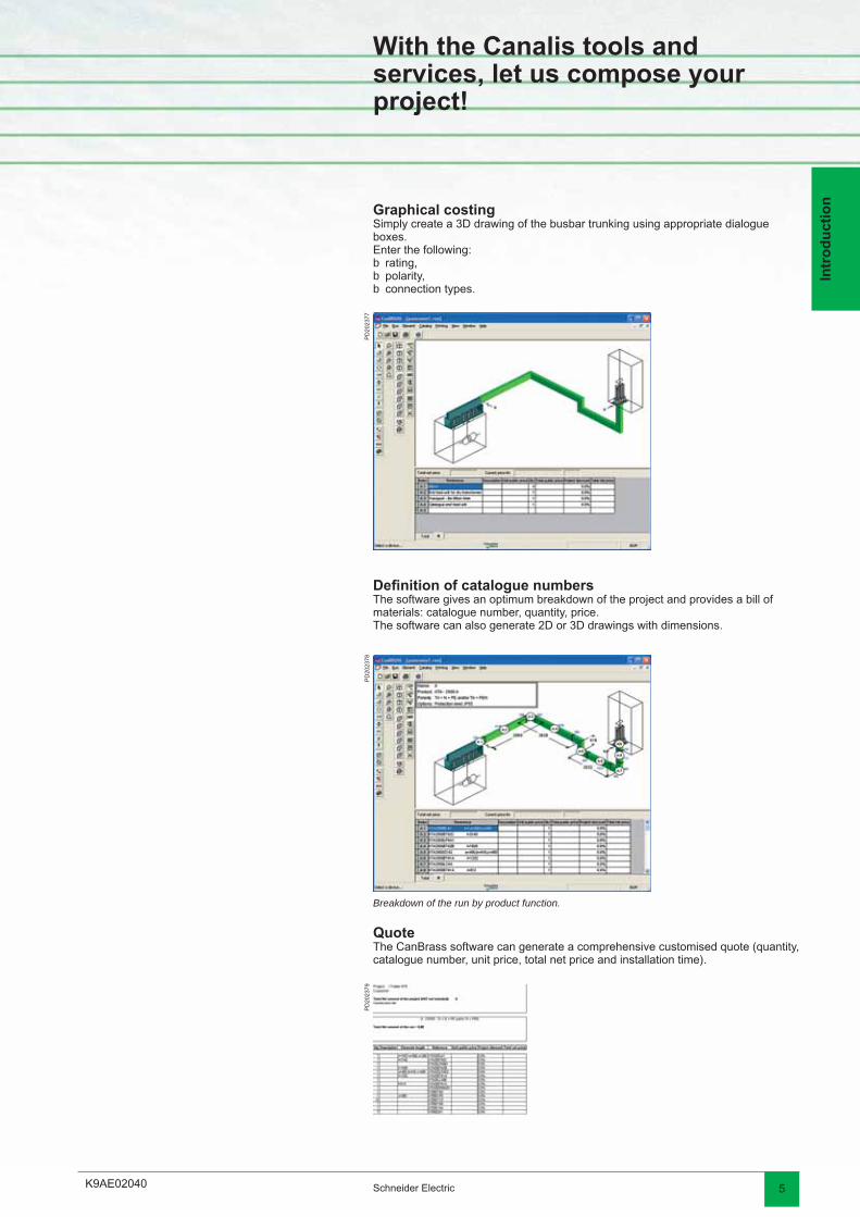
With the Canalis tools and services, let us compose your project!
Defi nition of catalogue numbersThe software gives an optimum breakdown of the project and provides a bill of materials: catalogue number, quantity, price.The software can also generate 2D or 3D drawings with dimensions.
Breakdown of the run by product function.
QuoteThe CanBrass software can generate a comprehensive customised quote (quantity, catalogue number, unit price, total net price and installation time).
Graphical costingSimply create a 3D drawing of the busbar trunking using appropriate dialogue boxes.Enter the following:
rating,polarity,connection types.
bbb
PD
2023
77P
D20
2378
PD
2023
79
K9AE110002 Schneider Electric
Pre
sen
tati
on
Presentation
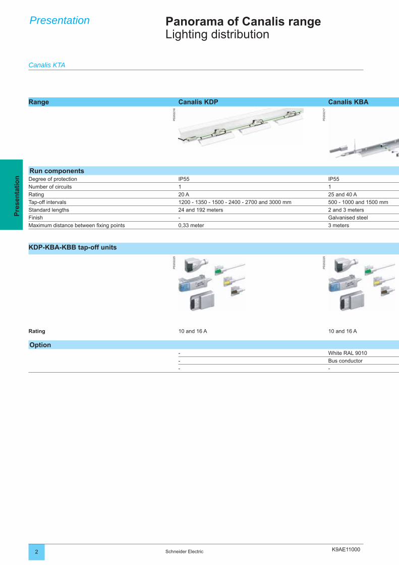
Range Canalis KDP Canalis KBA
PD
2022
16
PD
2022
17
Run componentsDegree of protection IP55 IP55
Number of circuits 1 1
Rating 20 A 25 and 40 A
Tap-off intervals 1200 - 1350 - 1500 - 2400 - 2700 and 3000 mm 500 - 1000 and 1500 mm
Standard lengths 24 and 192 meters 2 and 3 meters
Finish - Galvanised steel
Maximum distance between fi xing points 0,33 meter 3 meters
KDP-KBA-KBB tap-off units
PD
2022
25
PD
2022
25
Rating 10 and 16 A 10 and 16 A
Option- White RAL 9010
- Bus conductor
- -
Panorama of Canalis rangeLighting distribution
Canalis KTA
K9AE11000 3Schneider Electric
Pre
sen
tati
on
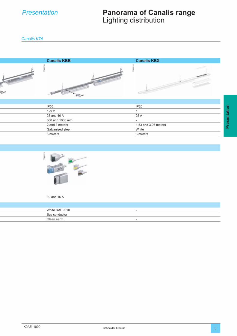
Canalis KBB Canalis KBX
PD
2022
19
PD
2022
20
IP55 IP20
1 or 2 1
25 and 40 A 25 A
500 and 1000 mm -
2 and 3 meters 1,53 and 3,06 meters
Galvanised steel White
5 meters 3 meters
PD
2022
25
10 and 16 A
White RAL 9010 -
Bus conductor -
Clean earth -
Presentation
Canalis KTA
Panorama of Canalis rangeLighting distribution
K9AE110004 Schneider Electric
Pre
sen
tati
on
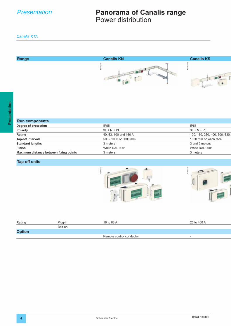
Range Canalis KN Canalis KS
PD
2022
21
PD
2022
22
Run componentsDegree of protection IP55 IP55
Polarity 3L + N + PE 3L + N + PE
Rating 40, 63, 100 and 160 A 100, 160, 250, 400, 500, 630,
Tap-off intervals 500 - 1000 or 3000 mm 1000 mm on each face
Standard lengths 3 meters 3 and 5 meters
Finish White RAL 9001 White RAL 9001
Maximum distance between fi xing points 3 meters 3 meters
Tap-off units
PD
2022
27
PD
2022
28
Rating Plug-in 16 to 63 A 25 to 400 A
Bolt-on
OptionRemote control conductor -
Presentation
Canalis KTA
Panorama of Canalis rangePower distribution
K9AE11000 5Schneider Electric
Pre
sen
tati
on
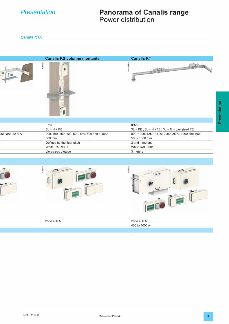
Canalis KS colonne montante Canalis KT
PD
2022
23
PD
2020
88-7
4
IP55 IP55
3L + N + PE 3L + PE ; 3L + N +PE ; 3L + N + oversized PE
800 and 1000 A 100, 160, 250, 400, 500, 630, 800 and 1000 A 800, 1000, 1250, 1600, 2000, 2500, 3200 and 4000
500 mm 500 - 1000 mm
Defi ned by the fl oor pitch 2 and 4 meters
White RAL 9001 White RAL 9001
Lié au pas d’étage 3 meters
PD
2022
28
PD
2022
29
25 to 400 A 25 to 400 A
400 to 1000 A
- -
Presentation
Canalis KTA
Panorama of Canalis rangePower distribution
K9AE11500
PD
2023
12P
D20
2328
2 Schneider Electric
Pre
sen
tati
on
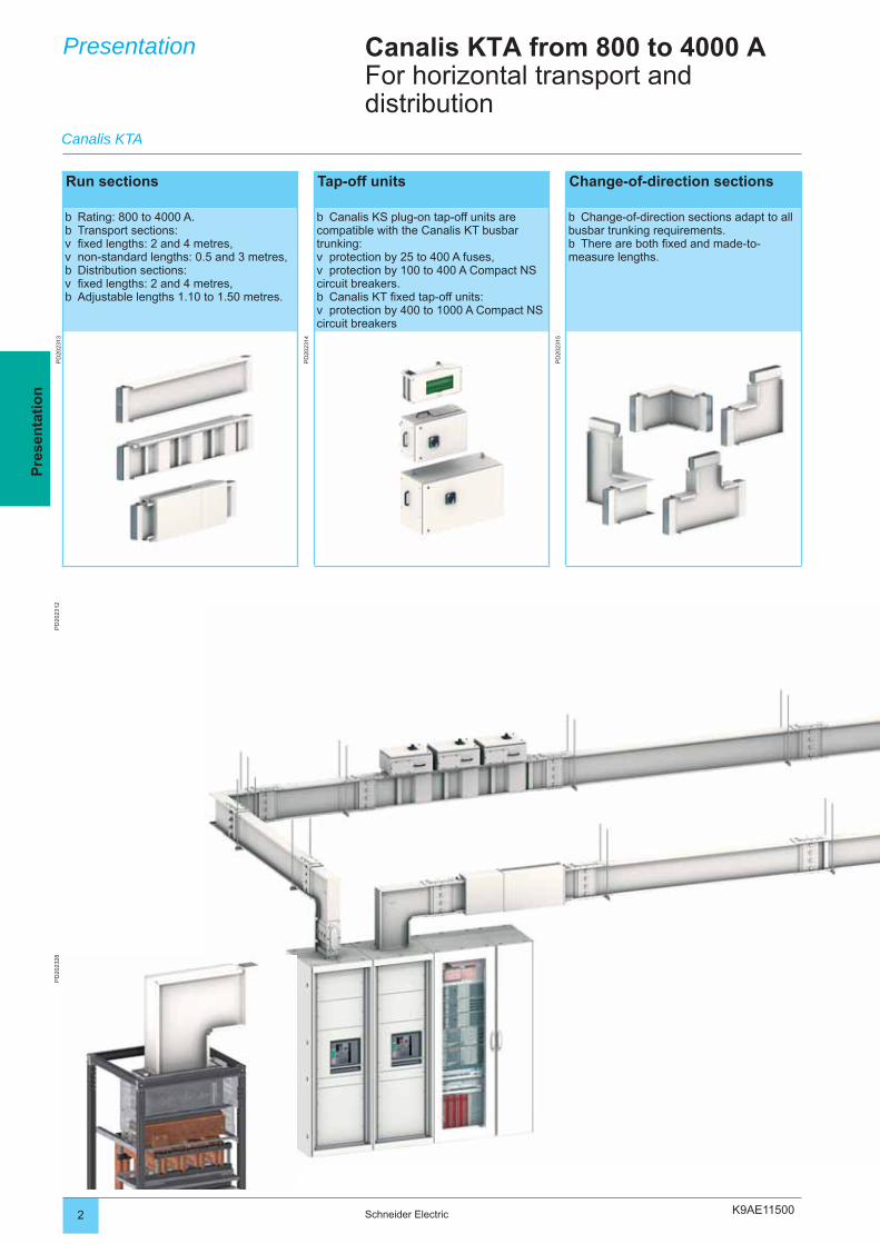
Canalis KTA from 800 to 4000 AFor horizontal transport and distribution
Presentation
Run sections Tap-off units Change-of-direction sections
Rating: 800 to 4000 A.Transport sections:fi xed lengths: 2 and 4 metres,non-standard lengths: 0.5 and 3 metres,Distribution sections:fi xed lengths: 2 and 4 metres,Adjustable lengths 1.10 to 1.50 metres.
bbvvbvb
Canalis KS plug-on tap-off units are compatible with the Canalis KT busbar trunking:
protection by 25 to 400 A fuses,protection by 100 to 400 A Compact NS
circuit breakers.Canalis KT fi xed tap-off units:protection by 400 to 1000 A Compact NS
circuit breakers
b
vv
bv
Change-of-direction sections adapt to all busbar trunking requirements.
There are both fi xed and made-to-measure lengths.
b
b
PD
2023
13
PD
2023
14
PD
2023
15
Canalis KTA
K9AE11500
PD
2023
00
3Schneider Electric
Pre
sen
tati
on
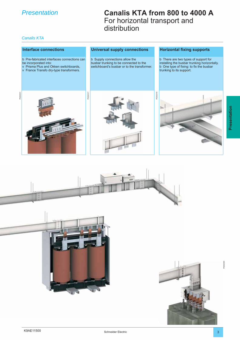
Presentation Canalis KTA from 800 to 4000 AFor horizontal transport and distribution
Interface connections Universal supply connections Horizontal fi xing supports
Pre-fabricated interfaces connections can be incorporated into:
Prisma Plus and Okken switchboards,France Transfo dry-type transformers.
b
vv
Supply connections allow the busbar trunking to be connected to the switchboard’s busbar or to the transformer.
b There are two types of support for installing the busbar trunking horizontally.
One type of fi xing: to fi x the busbar trunking to its support.
b
b
PD
2024
31
PD
2023
17
PD
2023
18
Canalis KTA
K9AE115004 Schneider Electric
Pre
sen
tati
on
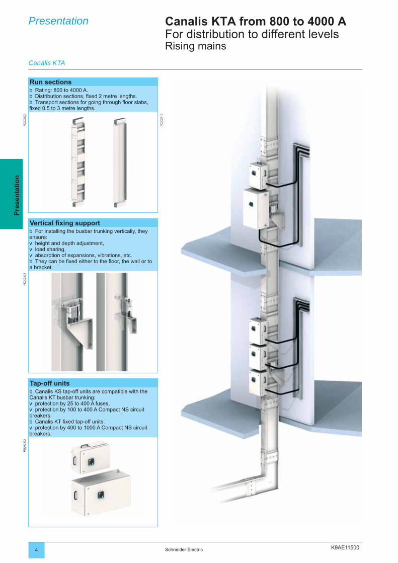
Run sectionsRating: 800 to 4000 A.Distribution sections, fi xed 2 metre lengths.Transport sections for going through fl oor slabs,
fi xed 0.5 to 3 metre lengths.
bbb
PD
2023
20
PD
2023
19
Vertical fi xing supportFor installing the busbar trunking vertically, they
ensure:height and depth adjustment,load sharing,absorption of expansions, vibrations, etc.They can be fi xed either to the fl oor, the wall or to
a bracket.
b
vvvb
PD
2023
21
Tap-off unitsCanalis KS tap-off units are compatible with the
Canalis KT busbar trunking:protection by 25 to 400 A fuses,protection by 100 to 400 A Compact NS circuit
breakers.Canalis KT fi xed tap-off units:protection by 400 to 1000 A Compact NS circuit
breakers.
b
vv
bv
PD
2023
22Presentation Canalis KTA from 800 to 4000 A
For distribution to different levelsRising mains
Canalis KTA
K9AE11500 5Schneider Electric
Pre
sen
tati
on
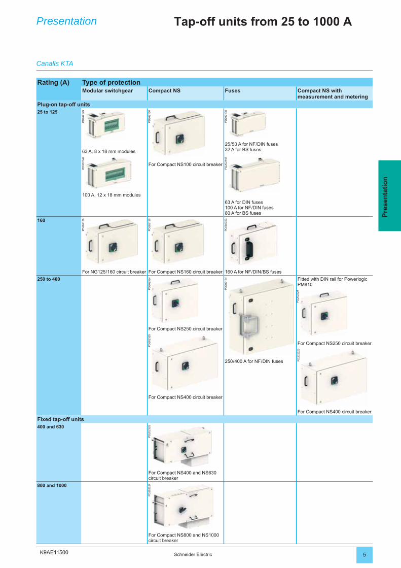
Rating (A) Type of protectionModular switchgear Compact NS Fuses Compact NS with
measurement and metering
Plug-on tap-off units25 to 125
PD
2021
49
PD
2021
50
PD
2021
38
25 / 50 A for NF / DIN fuses32 A for BS fuses63 A, 8 x 18 mm modules
PD
2021
48
PD
2021
47
For Compact NS100 circuit breaker
100 A, 12 x 18 mm modules
63 A for DIN fuses100 A for NF / DIN fuses80 A for BS fuses
160
PD
2021
50
PD
2021
50
PD
2023
23
For NG125 / 160 circuit breaker For Compact NS160 circuit breaker 160 A for NF / DIN / BS fuses
250 to 400
PD
2023
24
PD
2021
84 Fitted with DIN rail for Powerlogic PM810
PD
2023
24
For Compact NS250 circuit breaker
PD
2023
25
For Compact NS250 circuit breaker
PD
2023
25
250 / 400 A for NF / DIN fuses
For Compact NS400 circuit breaker
For Compact NS400 circuit breaker
Fixed tap-off units400 and 630
PD
2023
26
For Compact NS400 and NS630 circuit breaker
800 and 1000
PD
2023
27
For Compact NS800 and NS1000 circuit breaker
Tap-off units from 25 to 1000 APresentation
Canalis KTA
DD
2023
87D
D20
2388
DD
2023
89
DD
2024
34-m
DD
2024
35-m
DD
2024
36-m
DD
2024
45D
D20
2498
2 Schneider Electric
Des
crip
tio
n
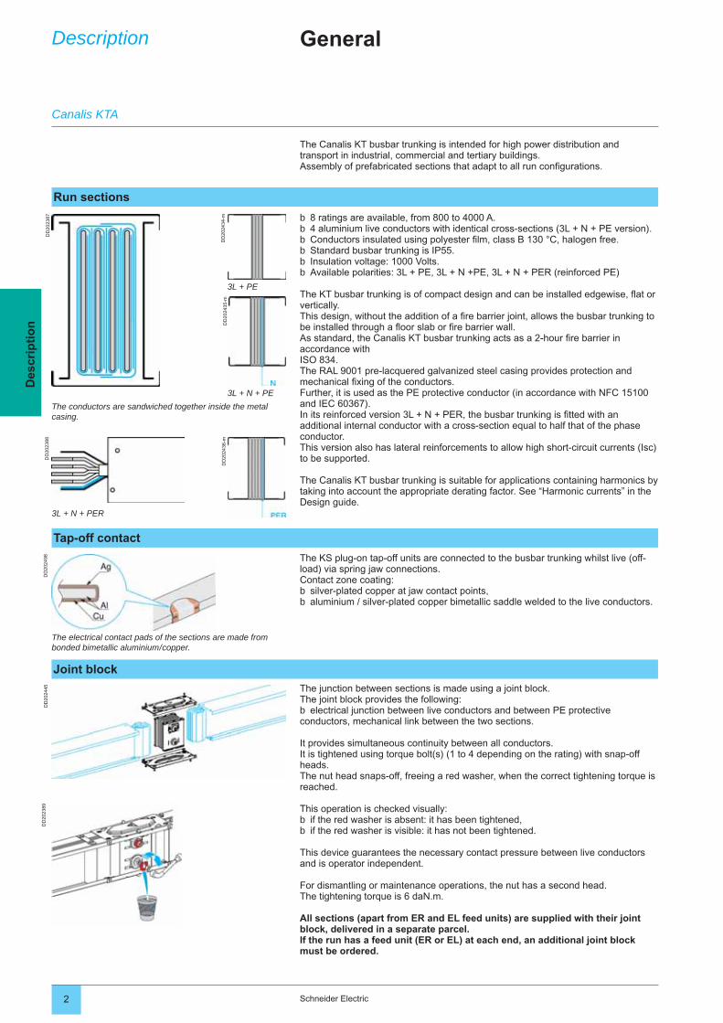
8 ratings are available, from 800 to 4000 A.4 aluminium live conductors with identical cross-sections (3L + N + PE version).Conductors insulated using polyester fi lm, class B 130 °C, halogen free.Standard busbar trunking is IP55.Insulation voltage: 1000 Volts.Available polarities: 3L + PE, 3L + N +PE, 3L + N + PER (reinforced PE)
The KT busbar trunking is of compact design and can be installed edgewise, fl at or vertically.This design, without the addition of a fi re barrier joint, allows the busbar trunking to be installed through a fl oor slab or fi re barrier wall.As standard, the Canalis KT busbar trunking acts as a 2-hour fi re barrier in accordance with ISO 834.The RAL 9001 pre-lacquered galvanized steel casing provides protection and mechanical fi xing of the conductors. Further, it is used as the PE protective conductor (in accordance with NFC 15100 and IEC 60367).In its reinforced version 3L + N + PER, the busbar trunking is fi tted with an additional internal conductor with a cross-section equal to half that of the phase conductor.This version also has lateral reinforcements to allow high short-circuit currents (Isc) to be supported.
The Canalis KT busbar trunking is suitable for applications containing harmonics by taking into account the appropriate derating factor. See “Harmonic currents” in the Design guide.
bbbbbb
The conductors are sandwiched together inside the metal casing.
The electrical contact pads of the sections are made from bonded bimetallic aluminium / copper.
The junction between sections is made using a joint block.The joint block provides the following:
electrical junction between live conductors and between PE protective conductors, mechanical link between the two sections.
It provides simultaneous continuity between all conductors.It is tightened using torque bolt(s) (1 to 4 depending on the rating) with snap-off heads.The nut head snaps-off, freeing a red washer, when the correct tightening torque is reached.
This operation is checked visually:if the red washer is absent: it has been tightened,if the red washer is visible: it has not been tightened.
This device guarantees the necessary contact pressure between live conductors and is operator independent.
For dismantling or maintenance operations, the nut has a second head.The tightening torque is 6 daN.m.
All sections (apart from ER and EL feed units) are supplied with their joint block, delivered in a separate parcel.If the run has a feed unit (ER or EL) at each end, an additional joint block must be ordered.
b
bb
The KS plug-on tap-off units are connected to the busbar trunking whilst live (off-load) via spring jaw connections.Contact zone coating:
silver-plated copper at jaw contact points,aluminium / silver-plated copper bimetallic saddle welded to the live conductors.
bb
3L + N + PER
Description
The Canalis KT busbar trunking is intended for high power distribution and transport in industrial, commercial and tertiary buildings. Assembly of prefabricated sections that adapt to all run confi gurations.
General
3L + PE
3L + N + PE
Run sections
Tap-off contact
Joint block
Canalis KTA
DD
2023
90D
D20
2438
DD
2024
37D
D20
2483
3Schneider Electric
Des
crip
tio
n
Run sections
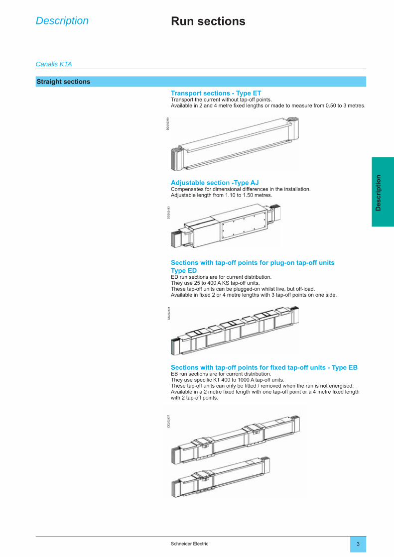
Transport sections - Type ETTransport the current without tap-off points.Available in 2 and 4 metre fi xed lengths or made to measure from 0.50 to 3 metres.
Adjustable section -Type AJCompensates for dimensional differences in the installation.Adjustable length from 1.10 to 1.50 metres.
Sections with tap-off points for plug-on tap-off unitsType EDED run sections are for current distribution. They use 25 to 400 A KS tap-off units.These tap-off units can be plugged-on whilst live, but off-load.Available in fi xed 2 or 4 metre lengths with 3 tap-off points on one side.
Sections with tap-off points for fi xed tap-off units - Type EBEB run sections are for current distribution. They use specifi c KT 400 to 1000 A tap-off units.These tap-off units can only be fi tted / removed when the run is not energised.Available in a 2 metre fi xed length with one tap-off point or a 4 metre fi xed length with 2 tap-off points.
Description
Canalis KTA
Straight sections
DD
2023
91D
D20
2392
DD
2024
39D
D20
2441
DD
2024
40D
D20
2446
DD
2108
11A
DD
2108
13
4 Schneider Electric
Des
crip
tio
n
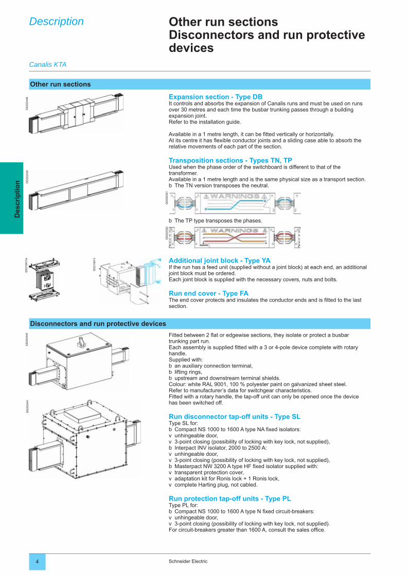
The TP type transposes the phases.b
Expansion section - Type DBIt controls and absorbs the expansion of Canalis runs and must be used on runs over 30 metres and each time the busbar trunking passes through a building expansion joint.Refer to the installation guide.
Available in a 1 metre length, it can be fi tted vertically or horizontally.At its centre it has fl exible conductor joints and a sliding case able to absorb the relative movements of each part of the section.
Transposition sections - Types TN, TPUsed when the phase order of the switchboard is different to that of the transformer.Available in a 1 metre length and is the same physical size as a transport section.
The TN version transposes the neutral.b
Additional joint block - Type YAIf the run has a feed unit (supplied without a joint block) at each end, an additional joint block must be ordered.Each joint block is supplied with the necessary covers, nuts and bolts.
Run end cover - Type FAThe end cover protects and insulates the conductor ends and is fi tted to the last section.
Other run sectionsDisconnectors and run protective devices
Fitted between 2 fl at or edgewise sections, they isolate or protect a busbar trunking part run.Each assembly is supplied fi tted with a 3 or 4-pole device complete with rotary handle.Supplied with:
an auxiliary connection terminal,lifting rings,upstream and downstream terminal shields.
Colour: white RAL 9001, 100 % polyester paint on galvanized sheet steel.Refer to manufacturer’s data for switchgear characteristics.Fitted with a rotary handle, the tap-off unit can only be opened once the device has been switched off.
Run disconnector tap-off units - Type SLType SL for:
Compact NS 1000 to 1600 A type NA fi xed isolators:unhingeable door,3-point closing (possibility of locking with key lock, not supplied),Interpact INV isolator, 2000 to 2500 A:unhingeable door,3-point closing (possibility of locking with key lock, not supplied),Masterpact NW 3200 A type HF fi xed isolator supplied with:transparent protection cover,adaptation kit for Ronis lock + 1 Ronis lock,complete Harting plug, not cabled.
Run protection tap-off units - Type PLType PL for:
Compact NS 1000 to 1600 A type N fi xed circuit-breakers:unhingeable door,3-point closing (possibility of locking with key lock, not supplied).
For circuit-breakers greater than 1600 A, consult the sales offi ce.
bbb
bvvbvvbvvv
bvv
Description
Canalis KTA
Other run sections
Disconnectors and run protective devices
DD
2023
93D
D20
2394
DD
2023
95D
D20
2396
DD
2023
97D
D20
2398
DD
2024
33D
D20
2432
5Schneider Electric
Des
crip
tio
n
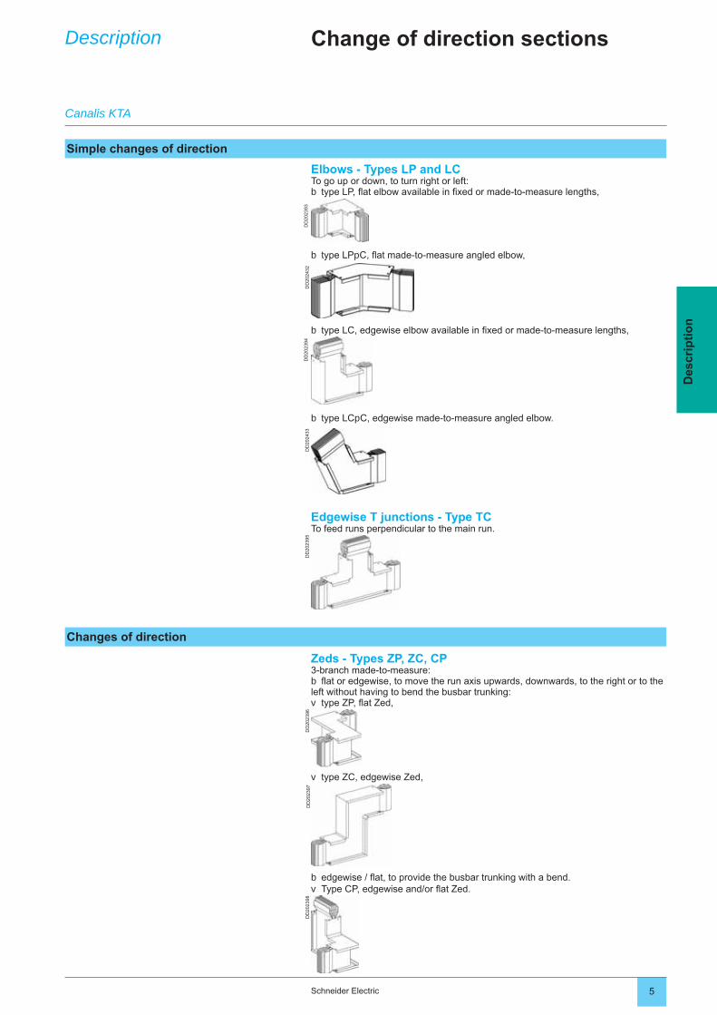
Elbows - Types LP and LCTo go up or down, to turn right or left:
type LP, fl at elbow available in fi xed or made-to-measure lengths,b
Zeds - Types ZP, ZC, CP3-branch made-to-measure:fl at or edgewise, to move the run axis upwards, downwards, to the right or to the
left without having to bend the busbar trunking:type ZP, fl at Zed,
b
v
Edgewise T junctions - Type TCTo feed runs perpendicular to the main run.
Change of direction sectionsDescription
type LPpC, fl at made-to-measure angled elbow,b
type LC, edgewise elbow available in fi xed or made-to-measure lengths,b
type LCpC, edgewise made-to-measure angled elbow.b
type ZC, edgewise Zed,v
edgewise / fl at, to provide the busbar trunking with a bend.Type CP, edgewise and/or fl at Zed.
bv
Canalis KTA
Simple changes of direction
Changes of direction
DD
2023
06D
D20
2310
DD
2023
14
6 Schneider Electric
Des
crip
tio
n
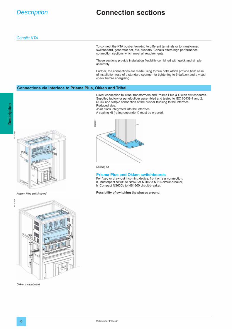
To connect the KTA busbar trunking to different terminals or to transformer, switchboard, generator set, etc. busbars. Canalis offers high performance connection sections which meet all requirements.
These sections provide installation fl exibility combined with quick and simple assembly.
Further, the connections are made using torque bolts which provide both ease of installation (use of a standard spanner for tightening to 6 daN.m) and a visual check before energising.
Direct connection to Trihal transformers and Prisma Plus & Okken switchboards.Supplied factory or panelbuilder assembled and tested to IEC 60439-1 and 2.Quick and simple connection of the busbar trunking to the interface.Reduced size.Joint block integrated into the interface.A sealing kit (rating dependent) must be ordered.
Connection sectionsDescription
Sealing kit
Prisma Plus and Okken switchboardsFor fi xed or draw-out incoming device, front or rear connection:
Masterpact NW08 to NW40 or NT06 to NT16 circuit-breaker,Compact NS630b to NS1600 circuit-breaker.
Possibility of switching the phases around.
bb
Prisma Plus switchboard
Okken switchboard
Canalis KTA
Connections via interface to Prisma Plus, Okken and Trihal
DD
2025
03
7Schneider Electric
Des
crip
tio
n
Connection sectionsDescription
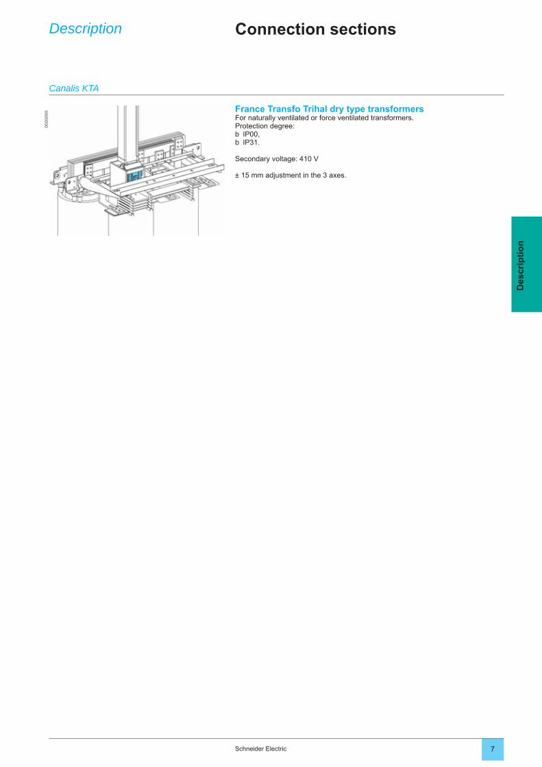
France Transfo Trihal dry type transformersFor naturally ventilated or force ventilated transformers.Protection degree:
IP00,IP31.
Secondary voltage: 410 V
± 15 mm adjustment in the 3 axes.
bb
Canalis KTA
DD
2023
99
DD
2107
77D
D20
2502
8 Schneider Electric
Des
crip
tio
n
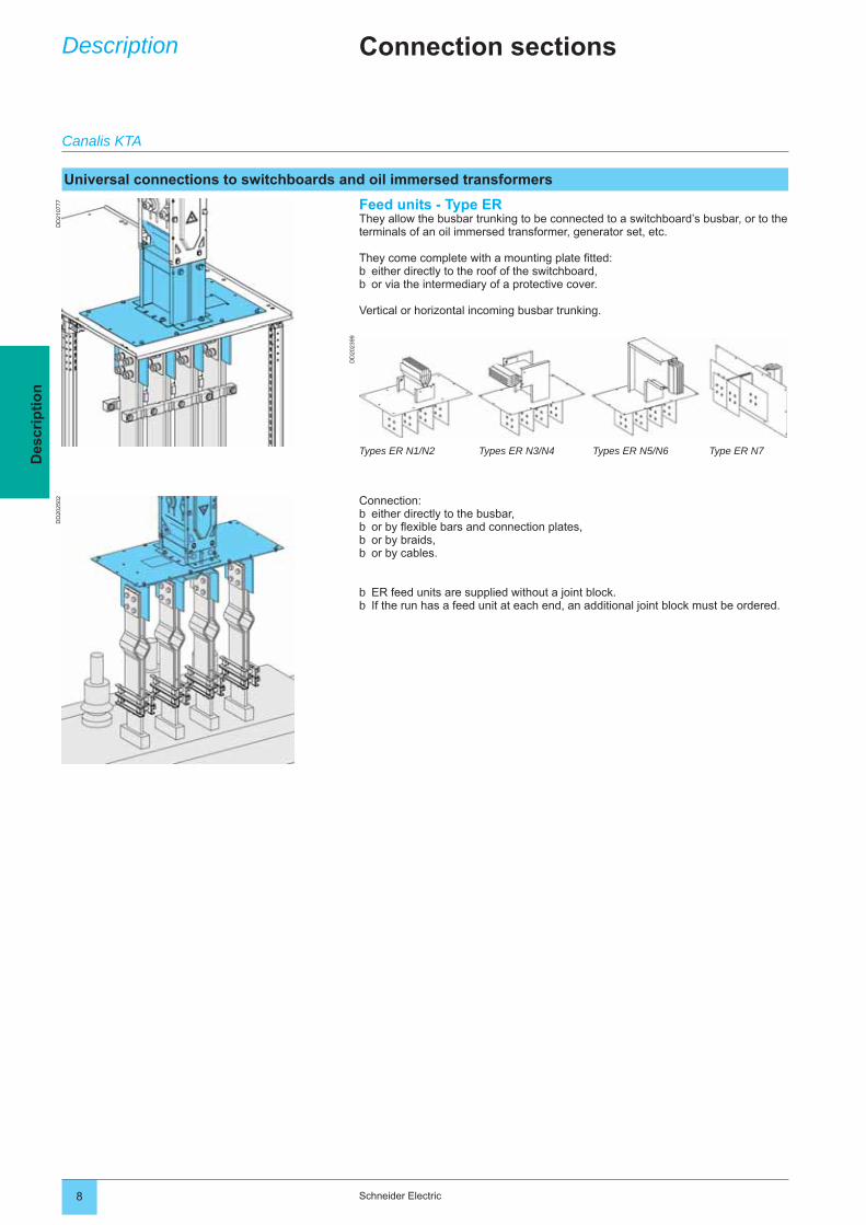
Feed units - Type ERThey allow the busbar trunking to be connected to a switchboard’s busbar, or to the terminals of an oil immersed transformer, generator set, etc.
They come complete with a mounting plate fi tted:either directly to the roof of the switchboard,or via the intermediary of a protective cover.
Vertical or horizontal incoming busbar trunking.
bb
Connection:either directly to the busbar,or by fl exible bars and connection plates,or by braids,or by cables.
ER feed units are supplied without a joint block.If the run has a feed unit at each end, an additional joint block must be ordered.
bbbb
bb
Types ER N1/N2
Connection sectionsDescription
Canalis KTA
Universal connections to switchboards and oil immersed transformers
Types ER N3/N4 Types ER N5/N6 Type ER N7
DD
2023
21D
D20
2325
1027
6 -0
3-d1
1027
6-3
03-d
4D
D20
5623
DD
2056
24
9Schneider Electric
Des
crip
tio
n
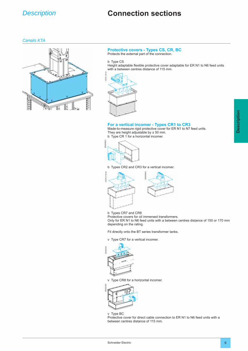
Protective covers - Types CS, CR, BCProtects the external part of the connection.
Type CSHeight adaptable fl exible protective cover adaptable for ER N1 to N6 feed units with a between centres distance of 115 mm.
b
Connection sectionsDescription
For a vertical incomer - Types CR1 to CR3Made-to-measure rigid protective cover for ER N1 to N7 feed units.They are height adjustable by ± 50 mm.
Type CR 1 for a horizontal incomer.b
Types CR7 and CR8Protective covers for oil immersed transformers.Only for ER N1 to N6 feed units with a between centres distance of 150 or 170 mm depending on the rating.
Fit directly onto the BT series transformer tanks.
Type CR7 for a vertical incomer.
b
v
Type BCProtective cover for direct cable connection to ER N1 to N6 feed units with a between centres distance of 115 mm.
v
Type CR8 for a horizontal incomer.v
Canalis KTA
Types CR2 and CR3 for a vertical incomer.b
DD
2024
44
DD
2024
43D
D20
2442
DD
2024
48D
D20
2447
10 Schneider Electric
Des
crip
tio
n
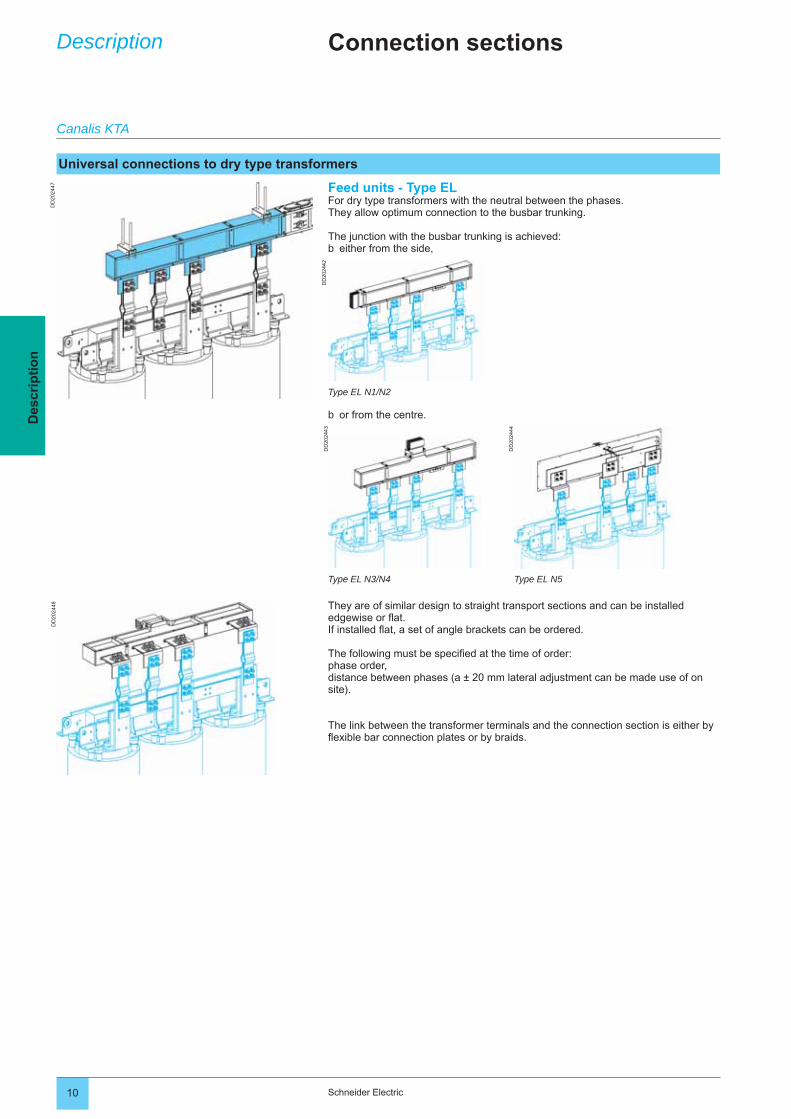
Feed units - Type ELFor dry type transformers with the neutral between the phases.They allow optimum connection to the busbar trunking.
The junction with the busbar trunking is achieved:either from the side,b
Connection sectionsDescription
They are of similar design to straight transport sections and can be installed edgewise or fl at.If installed fl at, a set of angle brackets can be ordered.
The following must be specifi ed at the time of order:phase order,distance between phases (a ± 20 mm lateral adjustment can be made use of on site).
The link between the transformer terminals and the connection section is either by fl exible bar connection plates or by braids.
Type EL N1/N2
or from the centre.b
Type EL N3/N4 Type EL N5
Canalis KTA
Universal connections to dry type transformers
DD
2023
43D
D20
2346
DD
2023
42
11Schneider Electric
Des
crip
tio
n
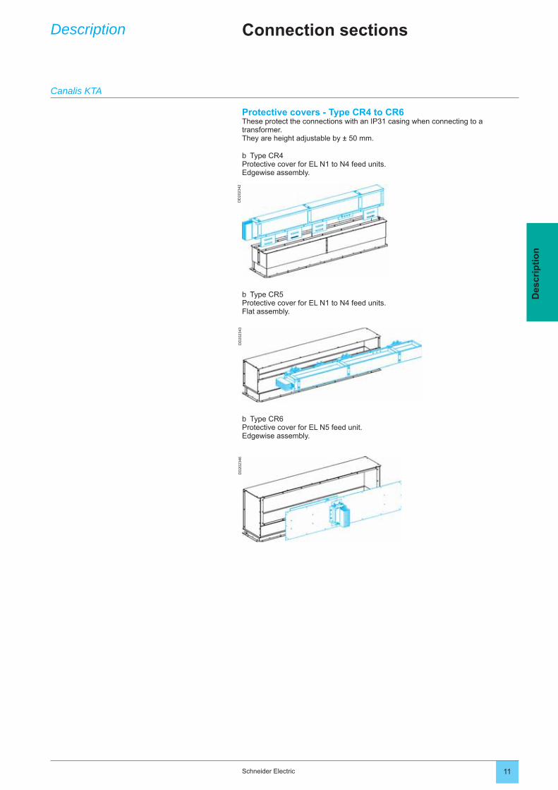
Protective covers - Type CR4 to CR6These protect the connections with an IP31 casing when connecting to a transformer.They are height adjustable by ± 50 mm.
Type CR4Protective cover for EL N1 to N4 feed units.Edgewise assembly.
b
Connection sectionsDescription
Type CR5Protective cover for EL N1 to N4 feed units.Flat assembly.
b
Type CR6Protective cover for EL N5 feed unit.Edgewise assembly.
b
Canalis KTA
DD
2024
00
DD
2024
11
DD
2024
10
DD
2024
03D
D20
2402
DD202401
DD
2023
63D
D20
2478
DD
2107
84
12 Schneider Electric
Des
crip
tio
n
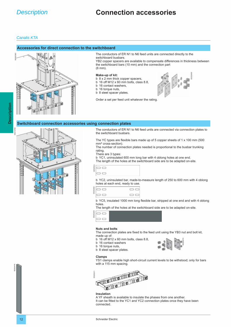
The conductors of ER N1 to N6 feed units are connected directly to the switchboard busbars.YB2 copper spacers are available to compensate differences in thickness between the switchboard bars (10 mm) and the connection part (6 mm).
Make-up of kit:8 x 2 mm thick copper spacers,16 off M12 x 60 mm bolts, class 8.8,16 contact washers,16 torque nuts,8 steel spacer plates.
Order a set per feed unit whatever the rating.
bbbbb
The conductors of ER N1 to N6 feed units are connected via connection plates to the switchboard busbars.
The YC types are fl exible bars made up of 5 copper sheets of 1 x 100 mm (500 mm² cross-section).The number of connection plates needed is proportional to the busbar trunking rating.There are 3 types:
YC1, uninsulated 600 mm long bar with 4 oblong holes at one end.The length of the holes at the switchboard side are to be adapted on-site.b
Connection accessoriesDescription
YC2, uninsulated bar, made-to-measure length of 250 to 600 mm with 4 oblong holes at each end, ready to use.b
YC5, insulated 1000 mm long fl exible bar, stripped at one end and with 4 oblong holes.The length of the holes at the switchboard side are to be adapted on-site.
b
Nuts and boltsThe connection plates are fi xed to the feed unit using the YB3 nut and bolt kit, made up of:
16 off M12 x 60 mm bolts, class 8.8,16 contact washers16 torque nuts,8 steel spacer plates.
ClampsYS1 clamps enable high short-circuit current levels to be withstood; only for bars with a 115 mm spacing.
bbbb
Canalis KTA
Switchboard connection accessories using connection plates
Accessories for direct connection to the switchboard
InsulationA YF sheath is available to insulate the phases from one another.It can be fi tted to the YC1 and YC2 connection plates once they have been connected.
DD
2024
12D
D20
2414
DD
2024
13D
D20
2415
DD
2024
50
13Schneider Electric
Des
crip
tio
n
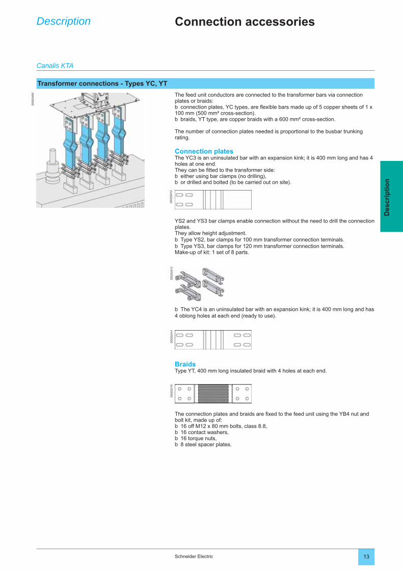
The feed unit conductors are connected to the transformer bars via connection plates or braids:
connection plates, YC types, are fl exible bars made up of 5 copper sheets of 1 x 100 mm (500 mm² cross-section).
braids, YT type, are copper braids with a 600 mm² cross-section.
The number of connection plates needed is proportional to the busbar trunking rating.
Connection platesThe YC3 is an uninsulated bar with an expansion kink; it is 400 mm long and has 4 holes at one end.They can be fi tted to the transformer side:
either using bar clamps (no drilling),or drilled and bolted (to be carried out on site).
b
b
bb
Connection accessoriesDescription
YS2 and YS3 bar clamps enable connection without the need to drill the connection plates.They allow height adjustment.
Type YS2, bar clamps for 100 mm transformer connection terminals.Type YS3, bar clamps for 120 mm transformer connection terminals.
Make-up of kit: 1 set of 8 parts.
bb
The YC4 is an uninsulated bar with an expansion kink; it is 400 mm long and has 4 oblong holes at each end (ready to use).b
BraidsType YT, 400 mm long insulated braid with 4 holes at each end.
The connection plates and braids are fi xed to the feed unit using the YB4 nut and bolt kit, made up of:
16 off M12 x 80 mm bolts, class 8.8,16 contact washers,16 torque nuts,8 steel spacer plates.
bbbb
Canalis KTA
Transformer connections - Types YC, YT
DD202372
DD
2024
84D
D20
2486
DD
2024
85
DD
2023
69D
D20
2368
DD
2024
96
DD
2023
74
14 Schneider Electric
Des
crip
tio
nSupports and fixings
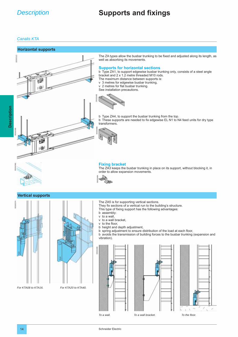
The ZA types allow the busbar trunking to be fi xed and adjusted along its length, as well as absorbing its movements.
Supports for horizontal sectionsType ZA1, to support edgewise busbar trunking only, consists of a steel angle
bracket and 2 x 1.2 metre threaded M10 rods. The maximum distance between supports is:
3 metres for edgewise busbar trunking,2 metres for fl at busbar trunking.
See installation precautions.
b
vv
Fixing bracketThe ZA3 keeps the busbar trunking in place on its support, without blocking it, in order to allow expansion movements.
The ZA5 is for supporting vertical sections.They fi x sections of a vertical run to the building’s structure.This type of fi xing support has the following advantages:
assembly:to a wall,to a wall bracket,to the fl oor,height and depth adjustment,spring adjustment to ensure distribution of the load at each fl oor,avoids the transmission of building forces to the busbar trunking (expansion and
vibration).
bvvvbbb
Description
Type ZA4, to support the busbar trunking from the top.These supports are needed to fi x edgewise EL N1 to N4 feed units for dry type
transformers.
bb
For KTA08 to KTA16. For KTA20 to KTA40.
To a wall. To a wall bracket. To the fl oor.
Canalis KTA
Horizontal supports
Vertical supports
K9AE13000
DD
2104
66D
D20
2012
DD
2102
75D
D21
0276
2 Schneider Electric
Des
crip
tio
nTap-off units
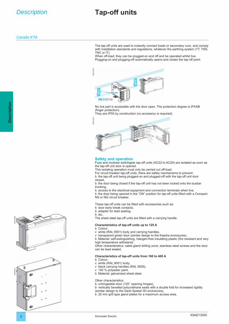
The tap-off units are used to instantly connect loads or secondary runs, and comply with installation standards and regulations, whatever the earthing system (TT, TNS, TNC or IT).When off-load, they can be plugged-on and off and be operated whilst live.Plugging-on and plugging-off automatically opens and closes the tap-off point.
Description
No live part is accessible with the door open. The protection degree is IPXXB (fi nger protection).They are IP55 by construction (no accessory is required).
Safety and operationFuse and modular switchgear tap-off units (AC22 to AC20) are isolated as soon as the tap-off unit door is opened.This isolating operation must only be carried out off-load.For circuit breaker tap-off units, there are safety mechanisms to prevent:
the tap-off unit being plugged-on and plugged-off with the tap-off unit door closed,
the door being closed if the tap-off unit has not been locked onto the busbar trunking,
access to the electrical equipment and connection terminals when live,the door being opened in the “ON” position for tap-off units fi tted with a Compact
NS or NG circuit breaker.
These tap-off units can be fi tted with accessories such as:door early break contacts,adapter for lead sealing,etc.
The sheet steel tap-off units are fi tted with a carrying handle.
Characteristics of tap-off units up to 125 AColour: white (RAL 9001) body and carrying handles,transparent green door (similar design to the Kaedra enclosures).Material: self-extinguishing, halogen-free insulating plastic (fi re resistant and very
high temperature withstand).Other characteristics: cable gland drilling zone, stainless steel screws and the door can be lead sealed.
Characteristics of tap-off units from 160 to 400 AColour:white (RAL 9001) body,black carrying handles (RAL 9005),100 % polyester paint.Material: galvanized sheet steel.
Other characteristics:unhingeable door (120° opening hinges),vertically bevelled polyurethane seals with a double fold for increased rigidity
(similar design to the Sarel Spatial 3D enclosures),25 mm grill type gland plates for a maximum access area.
b
b
bb
bbb
bvvb
bvvvb
bb
b
Canalis KTA
K9AE13000
DD
2104
65D
D21
0461
DD
2021
54D
D21
0454
3Schneider Electric
Des
crip
tio
n
Plug-on tap-off units for circuit breakers
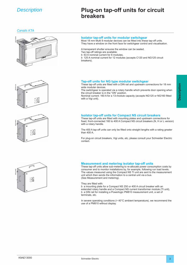
Isolator tap-off units for modular switchgearMost 18 mm Multi 9 modular devices can be fi tted into these tap-off units.They have a window on the front face for switchgear control and visualisation.
A transparent shutter ensures the window can be sealed.Two tap-off ratings are available:
63 A nominal current for 8 modules,125 A nominal current for 12 modules (accepts C120 and NG125 circuit
breakers).
bb
Tap-off units for NG type modular switchgearThese tap-off units are fi tted with a DIN rail and upstream connections for 18 mm wide modular devices.The switchgear is operated via a rotary handle which prevents door opening when the circuit breaker is in the “ON” position.Nominal current: 160 A for a 13-module capacity (accepts NG125 or NG160 fi tted with a Vigi unit).
Isolator tap-off units for Compact NS circuit breakersThese tap-off units are fi tted with mounting plates and upstream connections for fi xed, front-connected 160 to 400 A Compact NS circuit breakers (N, H or L version) with a rotary handle.
The 400 A tap-off units can only be fi tted onto straight lengths with a rating greater than 400 A.
For plug-on circuit breakers, Vigi units, etc, please consult your Schneider Electric contact.
Measurement and metering isolator tap-off unitsThese tap-off units allow sub-metering to re-allocate power consumption costs by consumer and to monitor installations by, for example, following run load levels.The values measured using the Compact NS TI unit are sent to the measurement unit which then sends the information to a central unit via a bus. (See Measurement and metering).
They are fi tted with:a mounting plate for a Compact NS 250 or 400 A circuit breaker with an
extended rotary handle and a Compact NS current transformer module (TI unit),a DIN rail for installing a Powerlogic PM810 measurement unit, a set of
terminals, etc.
In severe operating conditions (> 40°C ambient temperature), we recommend the use of a PM810 without display.
b
b
Description
Canalis KTA
K9AE13000
DD
2104
72D
D20
2012
DD
2104
66
4 Schneider Electric
Des
crip
tio
n
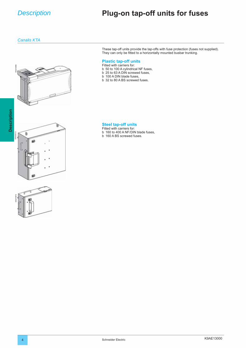
These tap-off units provide the tap-offs with fuse protection (fuses not supplied).They can only be fi tted to a horizontally mounted busbar trunking.
Plastic tap-off unitsFitted with carriers for:
50 to 100 A cylindrical NF fuses,25 to 63 A DIN screwed fuses,100 A DIN blade fuses,32 to 80 A BS screwed fuses.
bbbb
Plug-on tap-off units for fusesDescription
Steel tap-off unitsFitted with carriers for:
160 to 400 A NF / DIN blade fuses,160 A BS screwed fuses.
bb
Canalis KTA
K9AE13000
DD
2024
51D
D20
2497
5Schneider Electric
Des
crip
tio
n
Fixed tap-off units for circuit breakers
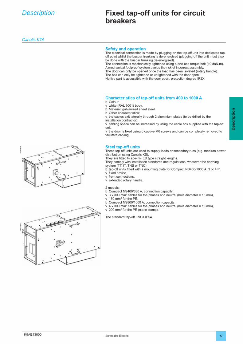
Steel tap-off unitsThese tap-off units are used to supply loads or secondary runs (e.g. medium power distribution using Canalis KS). They are fi tted to specifi c EB type straight lengths.They comply with installation standards and regulations, whatever the earthing system (TT, IT, TNS or TNC):
tap-off units fi tted with a mounting plate for Compact NS400/1000 A, 3 or 4 P:fi xed device,front connections,extended rotary handle.
2 models:Compact NS400/630 A, connection capacity: 3 x 300 mm2 cables for the phases and neutral (hole diameter = 15 mm),150 mm² for the PE,Compact NS800/1000 A, connection capacity:4 x 300 mm2 cables for the phases and neutral (hole diameter = 15 mm),200 mm2 for the PE (cable clamp).
The standard tap-off unit is IP54.
bvvv
bvvbvv
Characteristics of tap-off units from 400 to 1000 AColour:white (RAL 9001) body,Material: galvanized sheet steel.Other characteristics: the cables exit laterally through 2 aluminium plates (to be drilled by the
installation contractor),cabling space can be increased by using the cable box supplied with the tap-off
unit,the door is fi xed using 6 captive M6 screws and can be completely removed to
facilitate cabling.
bvbbv
v
v
Description
Safety and operationThe electrical connection is made by plugging-on the tap-off unit into dedicated tap-off point whilst the busbar trunking is de-energised (plugging-off the unit must also be done with the busbar trunking de-energised).The connection is mechanically tightened using a one-use torque bolt (10 daN.m).A mechanical foolproof system avoids the risk of incorrect assembly.The door can only be opened once the load has been isolated (rotary handle).The bolt can only be tightened or untightened with the door open.No live part is accessible with the door open, protection degree IP2X.
Canalis KTA

K9AE20000 Schneider Electric 3
Cat
alo
gu
e n
um
ber
sD
imen
sio
ns
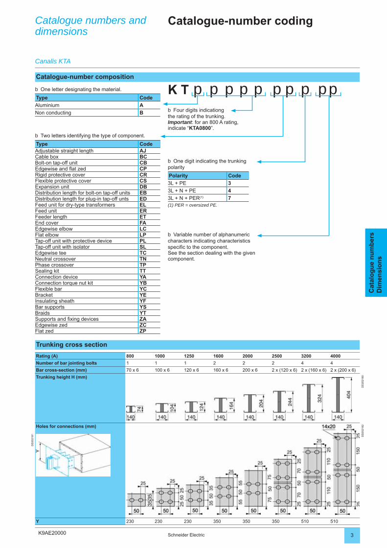
Catalogue-number coding
K T p p p p p p p p ppFour digits indicationg
the rating of the trunking.Important: for an 800 A rating, indicate “KTA0800”.
b
Two letters identifying the type of component.
Type CodeAdjustable straight length AJCable box BCBolt-on tap-off unit CBEdgewise and fl at zed CPRigid protective cover CRFlexible protective cover CSExpansion unit DBDistribution length for bolt-on tap-off units EBDistribution length for plug-in tap-off unts EDFeed unit for dry-type transformers ELFeed unit ERFeeder length ETEnd cover FAEdgewise elbow LCFlat elbow LPTap-off unit with protective device PLTap-off unit with isolator SLEdgewise tee TCNeutral crossover TNPhase crossover TPSealing kit TTConnection device YAConnection torque nut kit YBFlexible bar YCBracket YEInsulating sheath YFBar supports YSBraids YTSupports and fi xing devices ZAEdgewise zed ZCFlat zed ZP
b
One digit indicating the trunking polarity
Polarity Code
3L + PE 3
3L + N + PE 4
3L + N + PER(1) 7(1) PER = oversized PE.
b
Variable number of alphanumeric characters indicating characteristics specifi c to the component.See the section dealing with the given component.
b
Trunking cross section
Rating (A) 800 1000 1250 1600 2000 2500 3200 4000
Number of bar jointing bolts 1 1 1 2 2 2 4 4
Bar cross-section (mm) 70 x 6 100 x 6 120 x 6 160 x 6 200 x 6 2 x (120 x 6) 2 x (160 x 6) 2 x (200 x 6)
Trunking height H (mm)
DD
2021
80
DD
2021
81
Holes for connections (mm)
DD
2021
82
Y 230 230 230 350 350 350 510 510
Catalogue-number composition
One letter designating the material.
Type Code
Aluminium A
Non conducting B
b
Catalogue numbers anddimensions
Canalis KTA
K9AE21010
DD
2107
94
DD
2107
95
DD
2107
96
DD
2107
97
2 Schneider Electric
Cat
alo
gu
e n
um
ber
sD
imen
sio
ns
Catalogue numbers and dimensions
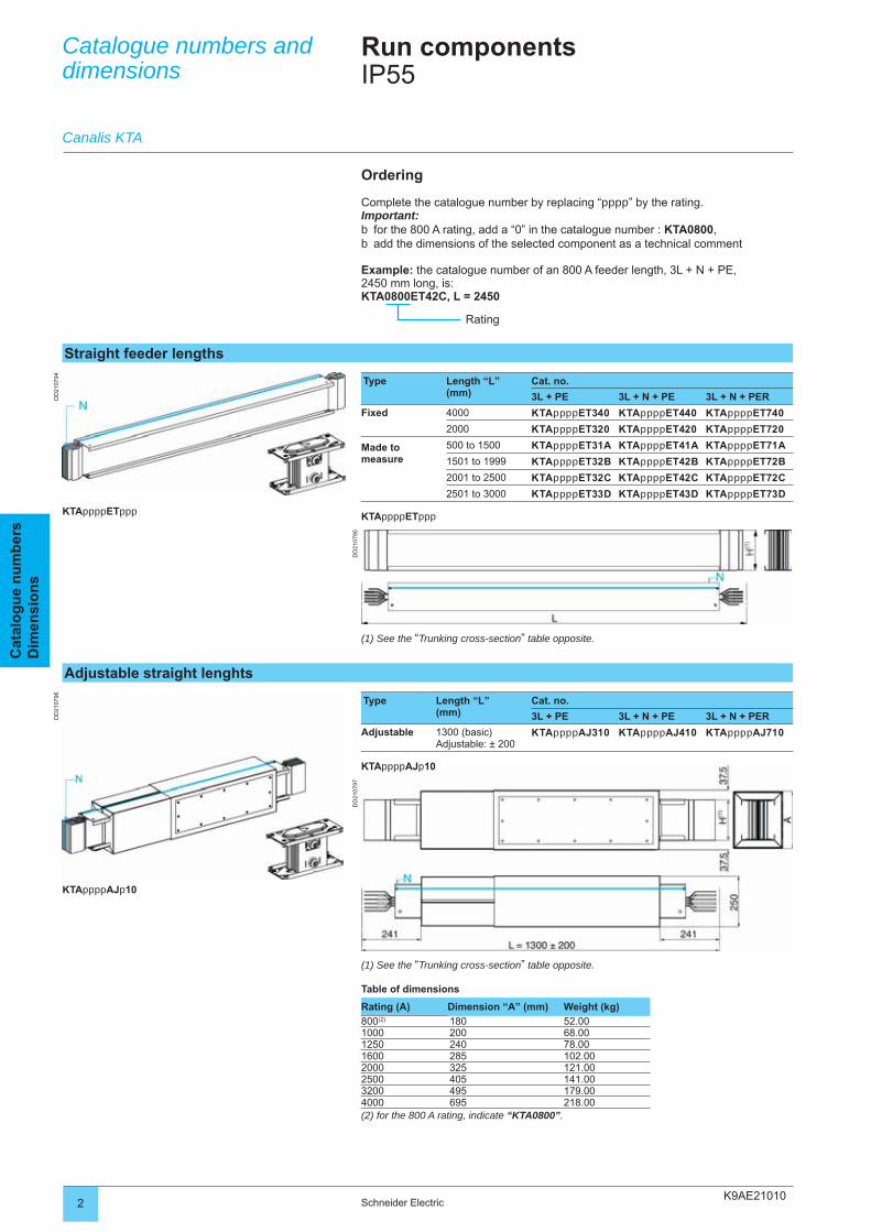
Straight feeder lengths
Run componentsIP55
Type Length “L”(mm)
Cat. no.
3L + PE 3L + N + PE 3L + N + PER
Fixed 4000 KTAppppET340 KTAppppET440 KTAppppET740
2000 KTAppppET320 KTAppppET420 KTAppppET720
Made to measure
500 to 1500 KTAppppET31A KTAppppET41A KTAppppET71A
1501 to 1999 KTAppppET32B KTAppppET42B KTAppppET72B
2001 to 2500 KTAppppET32C KTAppppET42C KTAppppET72C
2501 to 3000 KTAppppET33D KTAppppET43D KTAppppET73D
KTAppppETppp
Ordering
Complete the catalogue number by replacing “pppp” by the rating.Important:
for the 800 A rating, add a “0” in the catalogue number : KTA0800,add the dimensions of the selected component as a technical comment
Example: the catalogue number of an 800 A feeder length, 3L + N + PE,2450 mm long, is:KTA0800ET42C, L = 2450
bb
Rating
(1) See the “Trunking cross-section” table opposite.
Canalis KTA
Adjustable straight lenghts
Type Length “L”(mm)
Cat. no.
3L + PE 3L + N + PE 3L + N + PER
Adjustable 1300 (basic)Adjustable: ± 200
KTAppppAJ310 KTAppppAJ410 KTAppppAJ710
KTAppppAJp10
(1) See the “Trunking cross-section” table opposite.
Table of dimensions
Rating (A) Dimension “A” (mm) Weight (kg)
800(2) 180 52.001000 200 68.001250 240 78.001600 285 102.002000 325 121.002500 405 141.003200 495 179.004000 695 218.00(2) for the 800 A rating, indicate “KTA0800”.
KTAppppETppp
KTAppppAJp10
K9AE21010
DD
2107
98
DD
2107
99D
D21
0800
3Schneider Electric
Cat
alo
gu
e n
um
ber
sD
imen
sio
ns
Catalogue numbers and dimensions
Run componentsIP55
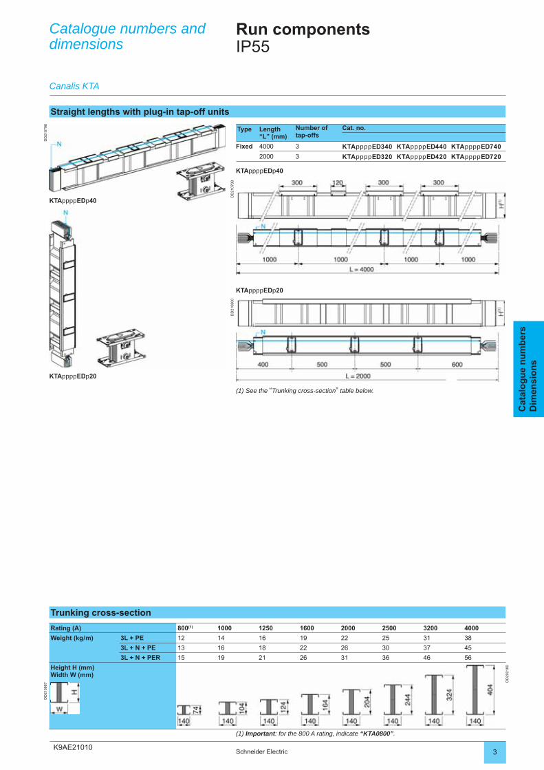
Straight lengths with plug-in tap-off units
Type Length “L” (mm)
Number of tap-offs
Cat. no.
Fixed 4000 3 KTAppppED340 KTAppppED440 KTAppppED740
2000 3 KTAppppED320 KTAppppED420 KTAppppED720
KTAppppEDp40
Trunking cross-section
Rating (A) 800(1) 1000 1250 1600 2000 2500 3200 4000
Weight (kg / m) 3L + PE 12 14 16 19 22 25 31 38
3L + N + PE 13 16 18 22 26 30 37 45
3L + N + PER 15 19 21 26 31 36 46 56
Height H (mm)Width W (mm)
DD
2021
80
DD
2108
67
(1) Important: for the 800 A rating, indicate “KTA0800”.
(1) See the “Trunking cross-section” table below.
Canalis KTA
KTAppppEDp20
KTAppppEDp20
KTAppppEDp40
K9AE21010
DD
2108
01
DD
2108
02D
D21
0803
DD
2107
66
4 Schneider Electric
Cat
alo
gu
e n
um
ber
sD
imen
sio
ns
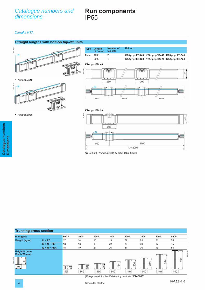
Straight lengths with bolt-on tap-off units
Type Length “L” (mm)
Number of tap-offs
Cat. no.
Fixed 4000 2 KTAppppEB340 KTAppppEB440 KTAppppEB740
2000 1 KTAppppEB320 KTAppppEB420 KTAppppEB720
KTAppppEBp40
(1) See the “Trunking cross-section” table below.
KTAppppEBp20
KTAppppEBp20
KTAppppEBp40
Trunking cross-section
Rating (A) 800(1) 1000 1250 1600 2000 2500 3200 4000
Weight (kg / m) 3L + PE 12 14 16 19 22 25 31 38
3L + N + PE 13 16 18 22 26 30 37 45
3L + N + PER 15 19 21 26 31 36 46 56
Height H (mm)Width W (mm)
DD
2021
80
DD
2108
67
(1) Important: for the 800 A rating, indicate “KTA0800”.
Catalogue numbers and dimensions
Canalis KTA
Run componentsIP55

K9AE210105Schneider Electric
Cat
alo
gu
e n
um
ber
sD
imen
sio
ns
K9AE21020
DD
2108
05
DD
2108
06
DD
2108
07
DD
2108
08
DD
2108
09
DD
2108
10
2 Schneider Electric
Cat
alo
gu
e n
um
ber
sD
imen
sio
ns
Catalogue numbers and dimensions
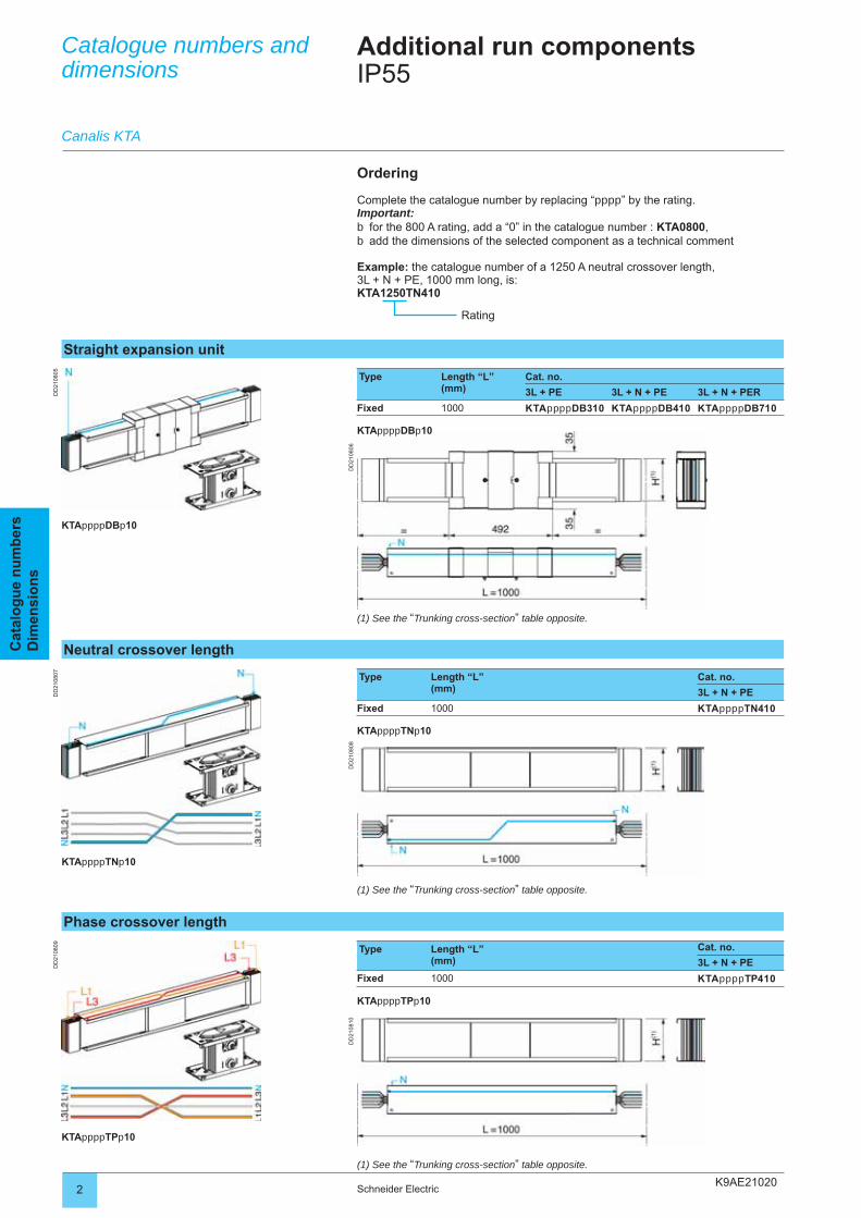
Straight expansion unit
Additional run componentsIP55
Type Length “L”(mm)
Cat. no.
3L + PE 3L + N + PE 3L + N + PER
Fixed 1000 KTAppppDB310 KTAppppDB410 KTAppppDB710
KTAppppDBp10
Ordering
Complete the catalogue number by replacing “pppp” by the rating.Important:
for the 800 A rating, add a “0” in the catalogue number : KTA0800,add the dimensions of the selected component as a technical comment
Example: the catalogue number of a 1250 A neutral crossover length,3L + N + PE, 1000 mm long, is:KTA1250TN410
bb
Rating
(1) See the “Trunking cross-section” table opposite.
Canalis KTA
Neutral crossover length
Type Length “L”(mm)
Cat. no.
3L + N + PE
Fixed 1000 KTAppppTN410
KTAppppTNp10
(1) See the “Trunking cross-section” table opposite.
Phase crossover length
Type Length “L”(mm)
Cat. no.
3L + N + PE
Fixed 1000 KTAppppTP410
KTAppppTPp10
(1) See the “Trunking cross-section” table opposite.
KTAppppDBp10
KTAppppTNp10
KTAppppTPp10
K9AE21020
DD
2108
11
DD
2108
12
DD
2108
13
DD
2108
14D
D21
0868
3Schneider Electric
Cat
alo
gu
e n
um
ber
sD
imen
sio
ns
Catalogue numbers and dimensions
Additional run componentsIP55
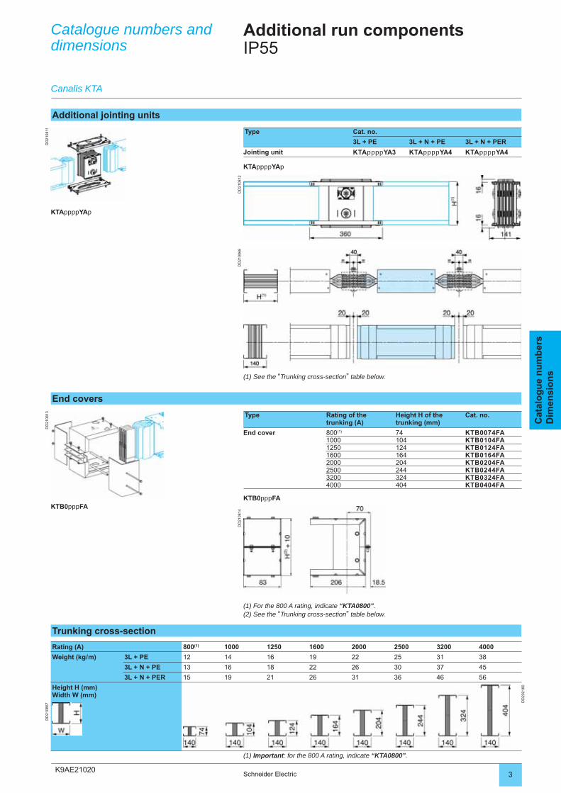
Additional jointing units
Type Cat. no.
3L + PE 3L + N + PE 3L + N + PER
Jointing unit KTAppppYA3 KTAppppYA4 KTAppppYA4
KTAppppYAp
(1) See the “Trunking cross-section” table below.
Canalis KTA
End covers
Type Rating of the trunking (A)
Height H of the trunking (mm)
Cat. no.
End cover 800(1) 74 KTB0074FA1000 104 KTB0104FA1250 124 KTB0124FA1600 164 KTB0164FA2000 204 KTB0204FA2500 244 KTB0244FA3200 324 KTB0324FA4000 404 KTB0404FA
KTB0pppFA
KTAppppYAp
KTB0pppFA
Trunking cross-section
Rating (A) 800(1) 1000 1250 1600 2000 2500 3200 4000
Weight (kg / m) 3L + PE 12 14 16 19 22 25 31 38
3L + N + PE 13 16 18 22 26 30 37 45
3L + N + PER 15 19 21 26 31 36 46 56
Height H (mm)Width W (mm)
DD
2021
80
DD
2108
67
(1) Important: for the 800 A rating, indicate “KTA0800”.
(1) For the 800 A rating, indicate “KTA0800”.(2) See the “Trunking cross-section” table below.
K9AE22010
DD
2108
22D
D21
0824
DD
2108
15D
D21
0816
DD
2108
21D
D21
0823
2 Schneider Electric
Cat
alo
gu
e n
um
ber
sD
imen
sio
ns
Catalogue numbers and dimensions
Elbow components for changing directionIP55
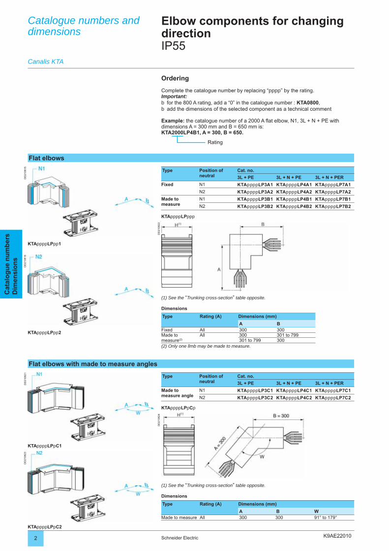
Flat elbows
Type Position of neutral
Cat. no.
3L + PE 3L + N + PE 3L + N + PER
Fixed N1 KTAppppLP3A1 KTAppppLP4A1 KTAppppLP7A1
N2 KTAppppLP3A2 KTAppppLP4A2 KTAppppLP7A2
Made to measure
N1 KTAppppLP3B1 KTAppppLP4B1 KTAppppLP7B1
N2 KTAppppLP3B2 KTAppppLP4B2 KTAppppLP7B2
KTAppppLPppp
Ordering
Complete the catalogue number by replacing “pppp” by the rating.Important:
for the 800 A rating, add a “0” in the catalogue number : KTA0800,add the dimensions of the selected component as a technical comment
Example: the catalogue number of a 2000 A fl at elbow, N1, 3L + N + PE with dimensions A = 300 mm and B = 650 mm is:KTA2000LP4B1, A = 300, B = 650.
bb
Rating
(1) See the “Trunking cross-section” table opposite.
Dimensions
Type Rating (A) Dimensions (mm)
A BFixed All 300 300Made to measure(2)
All 300 301 to 799301 to 799 300
(2) Only one llmb may be made to measure.
Canalis KTA
Flat elbows with made to measure angles
Type Position of neutral
Cat. no.
3L + PE 3L + N + PE 3L + N + PER
Made to measure angle
N1 KTAppppLP3C1 KTAppppLP4C1 KTAppppLP7C1
N2 KTAppppLP3C2 KTAppppLP4C2 KTAppppLP7C2
KTAppppLPpCp
(1) See the “Trunking cross-section” table opposite.
Dimensions
Type Rating (A) Dimensions (mm)
A B WMade to measure All 300 300 91° to 179°
KTAppppLPpp1
KTAppppLPpp2
KTAppppLPpC1
KTAppppLPpC2
K9AE22010
DD
2108
25
DD
2108
26
3Schneider Electric
Cat
alo
gu
e n
um
ber
sD
imen
sio
ns
Catalogue numbers and dimensions
Elbow components for changing directionIP55
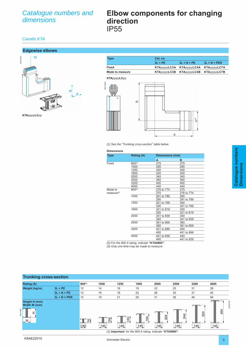
Edgewise elbows
Type Cat. no.
3L + PE 3L + N + PE 3L + N + PER
Fixed KTAppppLC3A KTAppppLC4A KTAppppLC7A
Made to measure KTAppppLC3B KTAppppLC4B KTAppppLC7B
KTAppppLCpp
(1) See the “Trunking cross-section” table below.
Dimensions
Type Rating (A) Dimensions (mm)
A BFixed 800(2) 275 275
1000 290 2901250 300 3001600 320 3202000 340 3402500 360 3603200 400 4004000 440 440
Made to measure(3)
800(2) 276 to 774 275275 276 to 774
1000 291 to 789 290290 291 to 789
1250 301 to 799 300300 301 to 799
1600 321 to 819 320320 321 to 819
2000 341 to 839 340340 341 to 839
2500 361 to 859 360360 361 to 859
3200 401 to 899 400400 401 to 899
4000 441 to 939 440440 441 to 939
(2) For the 800 A rating, indicate “KTA0800”.(3) Only one llmb may be made to measure.
Canalis KTA
KTAppppLCpp
Trunking cross-section
Rating (A) 800(1) 1000 1250 1600 2000 2500 3200 4000
Weight (kg / m) 3L + PE 12 14 16 19 22 25 31 38
3L + N + PE 13 16 18 22 26 30 37 45
3L + N + PER 15 19 21 26 31 36 46 56
Height H (mm)Width W (mm)
DD
2021
80
DD
2108
67
(1) Important: for the 800 A rating, indicate “KTA0800”.
K9AE22010
DD
2108
19
DD
2108
20
4 Schneider Electric
Cat
alo
gu
e n
um
ber
sD
imen
sio
ns
Catalogue numbers and dimensions
Canalis KTA
Elbow components for changing directionIP55
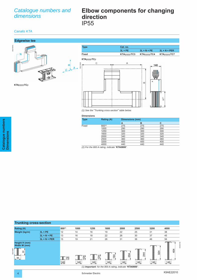
Edgewise tee
Type Cat. no.
3L + PE 3L + N + PE 3L + N + PER
Fixed KTAppppTC3 KTAppppTC4 KTAppppTC7
KTAppppTCp
KTAppppTCp
(1) See the “Trunking cross-section” table below.
Dimensions
Type Rating (A) Dimensions (mm)
A B CFixed 800(2) 275 275 275
1000 290 290 2901250 300 300 3001600 320 320 3202000 340 340 3402500 360 360 3603200 400 400 4004000 440 440 440
(2) For the 800 A rating, indicate “KTA0800”.
Trunking cross-section
Rating (A) 800(1) 1000 1250 1600 2000 2500 3200 4000
Weight (kg / m) 3L + PE 12 14 16 19 22 25 31 38
3L + N + PE 13 16 18 22 26 30 37 45
3L + N + PER 15 19 21 26 31 36 46 56
Height H (mm)Width W (mm)
DD
2021
80
DD
2108
67
(1) Important: for the 800 A rating, indicate “KTA0800”.
K9AE22010 5Schneider Electric
Cat
alo
gu
e n
um
ber
sD
imen
sio
ns
K9AE22020
DD
2021
83
DD
2021
84D
D20
2186
DD
2021
85D
D21
0827
2 Schneider Electric
Cat
alo
gu
e n
um
ber
sD
imen
sio
ns
Catalogue numbers and dimensions
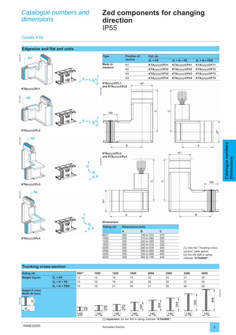
Zed components for changing directionIP55
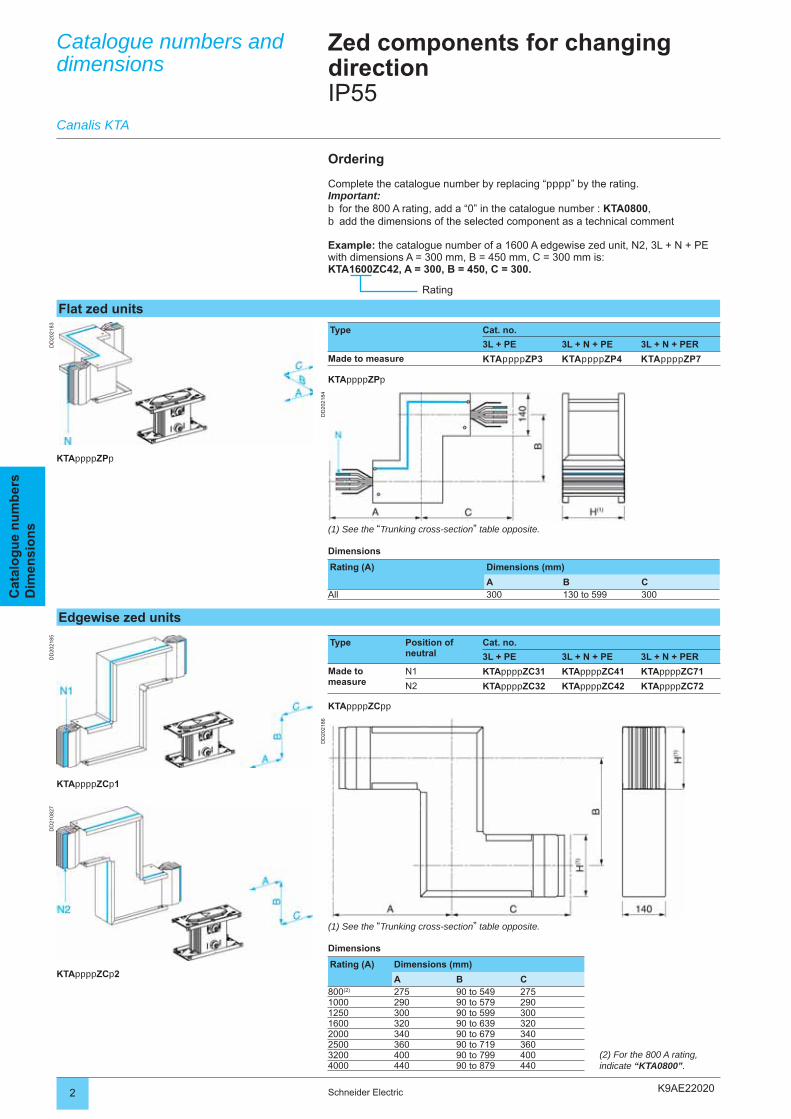
Edgewise zed units
Type Position of neutral
Cat. no.
3L + PE 3L + N + PE 3L + N + PER
Made to measure
N1 KTAppppZC31 KTAppppZC41 KTAppppZC71
N2 KTAppppZC32 KTAppppZC42 KTAppppZC72
KTAppppZCpp
Flat zed units
Type Cat. no.
3L + PE 3L + N + PE 3L + N + PER
Made to measure KTAppppZP3 KTAppppZP4 KTAppppZP7
KTAppppZPp
Ordering
Complete the catalogue number by replacing “pppp” by the rating.Important:
for the 800 A rating, add a “0” in the catalogue number : KTA0800,add the dimensions of the selected component as a technical comment
Example: the catalogue number of a 1600 A edgewise zed unit, N2, 3L + N + PE with dimensions A = 300 mm, B = 450 mm, C = 300 mm is:KTA1600ZC42, A = 300, B = 450, C = 300.
bb
Rating
(1) See the “Trunking cross-section” table opposite.
Dimensions
Rating (A) Dimensions (mm)
A B CAll 300 130 to 599 300
(1) See the “Trunking cross-section” table opposite.
Dimensions
Rating (A) Dimensions (mm)
A B C800(2) 275 90 to 549 2751000 290 90 to 579 2901250 300 90 to 599 3001600 320 90 to 639 3202000 340 90 to 679 3402500 360 90 to 719 3603200 400 90 to 799 4004000 440 90 to 879 440
KTAppppZPp
KTAppppZCp1
KTAppppZCp2
Canalis KTA
(2) For the 800 A rating, indicate “KTA0800”.
K9AE22020
DD
2021
87
DD
2021
88
DD
2108
28D
D21
0829
DD
2108
30
DD
2023
67
3Schneider Electric
Cat
alo
gu
e n
um
ber
sD
imen
sio
ns
Catalogue numbers and dimensions
Zed components for changing directionIP55
Edgewise and fl at zed units
Type Position of neutral
Cat. no.
3L + PE 3L + N + PE 3L + N + PERMade to measure
N1 KTAppppCP31 KTAppppCP41 KTAppppCP71
N2 KTAppppCP32 KTAppppCP42 KTAppppCP72
N3 KTAppppCP33 KTAppppCP43 KTAppppCP73
N4 KTAppppCP34 KTAppppCP44 KTAppppCP74
(1) See the “Trunking cross-section” table below.(2) For the 800 A rating, indicate “KTA0800”.
Canalis KTA
KTAppppCPp1
KTAppppCPp2
KTAppppCPp3
KTAppppCPp4
Trunking cross-section
Rating (A) 800(1) 1000 1250 1600 2000 2500 3200 4000
Weight (kg / m) 3L + PE 12 14 16 19 22 25 31 38
3L + N + PE 13 16 18 22 26 30 37 45
3L + N + PER 15 19 21 26 31 36 46 56
Height H (mm)Width W (mm)
DD
2021
80
DD
2108
67
(1) Important: for the 800 A rating, indicate “KTA0800”.
KTAppppCPp3and KTAppppCPp4
KTAppppCPp1and KTAppppCPp2
Dimensions
Rating (A) Dimensions (mm)
A B C800(2) 300 195 to 574 2751000 300 210 to 589 2901250 300 220 to 599 3001600 300 240 to 619 3202000 300 260 to 639 3402500 300 280 to 659 3603200 300 320 to 699 4004000 300 360 to 739 440
K9AE23000
DD
2023
04D
D20
2306
DD
2023
05D
D20
2307
2 Schneider Electric
Cat
alo
gu
e n
um
ber
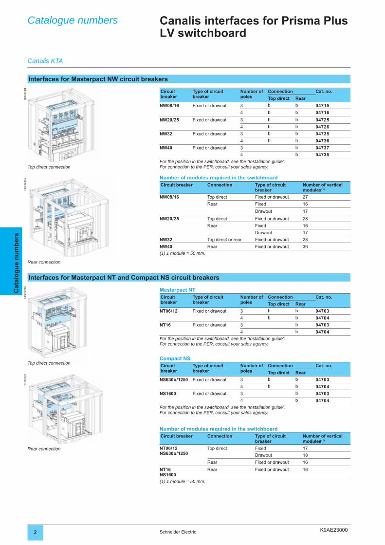
sCatalogue numbers Canalis interfaces for Prisma Plus
LV switchboard
Interfaces for Masterpact NW circuit breakers
Circuit breaker
Type of circuit breaker
Number of poles
Connection Cat. no.
Top direct Rear
NW08 / 16 Fixed or drawout 3 b b 04715
4 b b 04716
NW20 / 25 Fixed or drawout 3 b b 04725
4 b b 04726
NW32 Fixed or drawout 3 b b 04735
4 b b 04736
NW40 Fixed or drawout 3 b 04737
4 b 04738
For the position in the switchboard, see the “Installation guide”.For connection to the PER, consult your sales agency.
Number of modules required in the switchboardCircuit breaker Connection Type of circuit
breakerNumber of vertical modules(1)
NW08 / 16 Top direct Fixed or drawout 27
Rear Fixed 16
Drawout 17
NW20 / 25 Top direct Fixed or drawout 28
Rear Fixed 16
Drawout 17
NW32 Top direct or rear Fixed or drawout 28
NW40 Rear Fixed or drawout 36
(1) 1 module = 50 mm.
Canalis KTA
Interfaces for Masterpact NT and Compact NS circuit breakers
Masterpact NTCircuit breaker
Type of circuit breaker
Number of poles
Connection Cat. no.
Top direct Rear
NT06 / 12 Fixed or drawout 3 b b 04703
4 b b 04704
NT16 Fixed or drawout 3 b 04703
4 b 04704
For the position in the switchboard, see the “Installation guide”.For connection to the PER, consult your sales agency.
Compact NSCircuit breaker
Type of circuit breaker
Number of poles
Connection Cat. no.
Top direct Rear
NS630b / 1250 Fixed or drawout 3 b b 04703
4 b b 04704
NS1600 Fixed or drawout 3 b 04703
4 b 04704
For the position in the switchboard, see the “Installation guide”.For connection to the PER, consult your sales agency.
Number of modules required in the switchboardCircuit breaker Connection Type of circuit
breakerNumber of vertical modules(1)
NT06 / 12NS630b / 1250
Top direct Fixed 17
Drawout 18
Rear Fixed or drawout 16
NT16NS1600
Rear Fixed or drawout 16
(1) 1 module = 50 mm.
Top direct connection
Rear connection
Top direct connection
Rear connection
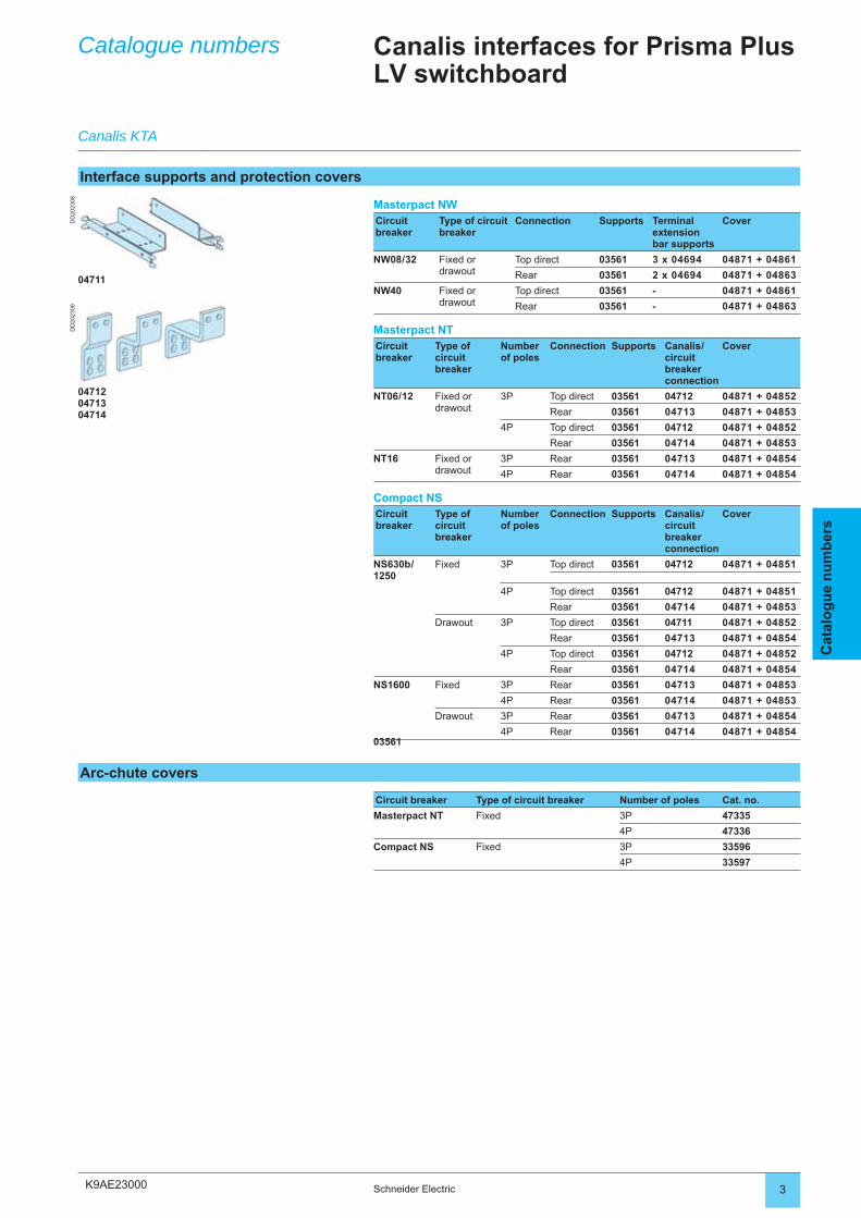
K9AE23000
DD
2023
08D
D20
2309
3Schneider Electric
Cat
alo
gu
e n
um
ber
s
Catalogue numbers
Canalis KTA
Canalis interfaces for Prisma Plus LV switchboard
Interface supports and protection covers
Masterpact NWCircuit breaker
Type of circuit breaker
Connection Supports Terminal extension bar supports
Cover
NW08 / 32 Fixed or drawout
Top direct 03561 3 x 04694 04871 + 04861
Rear 03561 2 x 04694 04871 + 04863
NW40 Fixed or drawout
Top direct 03561 - 04871 + 04861
Rear 03561 - 04871 + 04863
Masterpact NTCircuit breaker
Type of circuit breaker
Number of poles
Connection Supports Canalis /circuit breaker connection
Cover
NT06 / 12 Fixed or drawout
3P Top direct 03561 04712 04871 + 04852
Rear 03561 04713 04871 + 04853
4P Top direct 03561 04712 04871 + 04852
Rear 03561 04714 04871 + 04853
NT16 Fixed or drawout
3P Rear 03561 04713 04871 + 04854
4P Rear 03561 04714 04871 + 04854
Compact NSCircuit breaker
Type of circuit breaker
Number of poles
Connection Supports Canalis /circuit breaker connection
Cover
NS630b /1250
Fixed 3P Top direct 03561 04712 04871 + 04851
4P Top direct 03561 04712 04871 + 04851
Rear 03561 04714 04871 + 04853
Drawout 3P Top direct 03561 04711 04871 + 04852
Rear 03561 04713 04871 + 04854
4P Top direct 03561 04712 04871 + 04852
Rear 03561 04714 04871 + 04854
NS1600 Fixed 3P Rear 03561 04713 04871 + 04853
4P Rear 03561 04714 04871 + 04853
Drawout 3P Rear 03561 04713 04871 + 04854
4P Rear 03561 04714 04871 + 0485403561
04711
047120471304714
Arc-chute covers
Circuit breaker Type of circuit breaker Number of poles Cat. no.
Masterpact NT Fixed 3P 47335
4P 47336
Compact NS Fixed 3P 33596
4P 33597
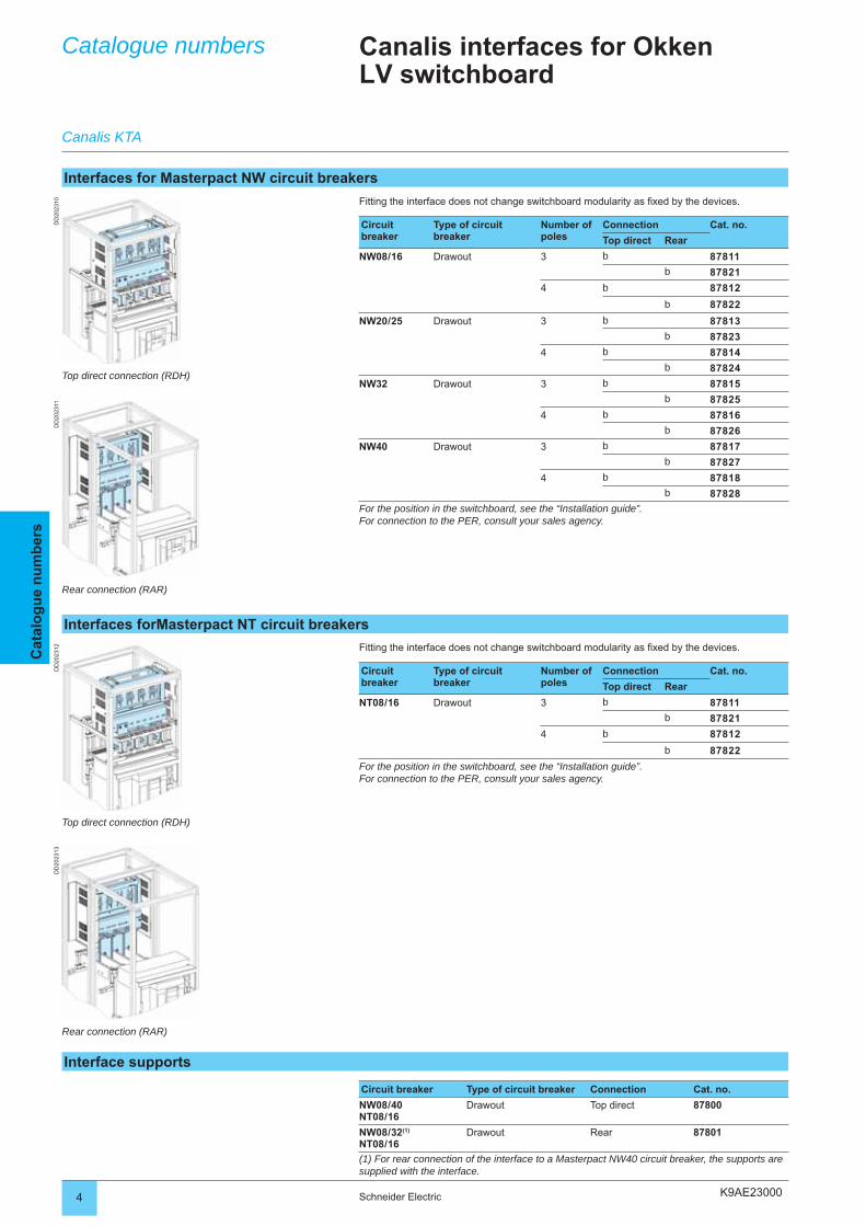
K9AE23000
DD
2023
10D
D20
2312
DD
2023
11D
D20
2313
4 Schneider Electric
Cat
alo
gu
e n
um
ber
sCatalogue numbers Canalis interfaces for Okken
LV switchboard
Interfaces for Masterpact NW circuit breakers
Fitting the interface does not change switchboard modularity as fi xed by the devices.
Circuit breaker
Type of circuit breaker
Number of poles
Connection Cat. no.
Top direct Rear
NW08 / 16 Drawout 3 b 87811
b 87821
4 b 87812
b 87822
NW20 / 25 Drawout 3 b 87813
b 87823
4 b 87814
b 87824
NW32 Drawout 3 b 87815
b 87825
4 b 87816
b 87826
NW40 Drawout 3 b 87817
b 87827
4 b 87818
b 87828
For the position in the switchboard, see the “Installation guide”.For connection to the PER, consult your sales agency.
Canalis KTA
Interfaces forMasterpact NT circuit breakers
Fitting the interface does not change switchboard modularity as fi xed by the devices.
Circuit breaker
Type of circuit breaker
Number of poles
Connection Cat. no.
Top direct Rear
NT08 / 16 Drawout 3 b 87811
b 87821
4 b 87812
b 87822
For the position in the switchboard, see the “Installation guide”.For connection to the PER, consult your sales agency.
Interface supports
Circuit breaker Type of circuit breaker Connection Cat. no.
NW08 / 40NT08 / 16
Drawout Top direct 87800
NW08 / 32(1)
NT08 / 16Drawout Rear 87801
(1) For rear connection of the interface to a Masterpact NW40 circuit breaker, the supports are supplied with the interface.
Top direct connection (RDH)
Rear connection (RAR)
Top direct connection (RDH)
Rear connection (RAR)
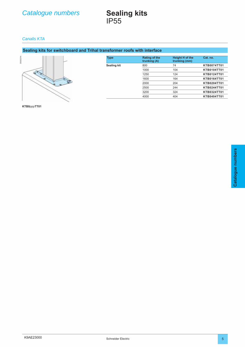
K9AE23000
DD
2023
14
5Schneider Electric
Cat
alo
gu
e n
um
ber
s
Catalogue numbers
Canalis KTA
Sealing kitsIP55
Sealing kits for switchboard and Trihal transformer roofs with interface
Type Rating of the trunking (A)
Height H of the trunking (mm)
Cat. no.
Sealing kit 800 74 KTB0074TT01
1000 104 KTB0104TT01
1250 124 KTB0124TT01
1600 164 KTB0164TT01
2000 204 KTB0204TT01
2500 244 KTB0244TT01
3200 324 KTB0324TT01
4000 404 KTB0404TT01
KTB0pppTT01
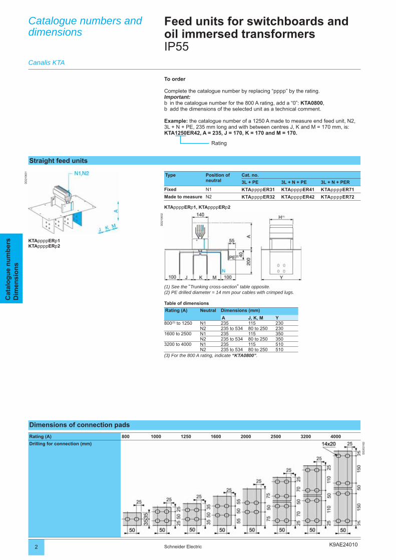
K9AE24010
DD
2108
31
DD
2108
32
2 Schneider Electric
Cat
alo
gu
e n
um
ber
sD
imen
sio
ns
Catalogue numbers and dimensions
Feed units for switchboards and oil immersed transformersIP55
Straight feed units
Type Position of neutral
Cat. no.
3L + PE 3L + N + PE 3L + N + PER
Fixed N1 KTAppppER31 KTAppppER41 KTAppppER71
Made to measure N2 KTAppppER32 KTAppppER42 KTAppppER72
KTAppppERp1, KTAppppERp2
To order
Complete the catalogue number by replacing “pppp” by the rating.Important:
in the catalogue number for the 800 A rating, add a “0”: KTA0800,add the dimensions of the selected unit as a technical comment.
Example: the catalogue number of a 1250 A made to measure end feed unit, N2, 3L + N + PE, 235 mm long and with between centres J, K and M = 170 mm, is: KTA1250ER42, A = 235, J = 170, K = 170 and M = 170.
bb
Rating
(1) See the “Trunking cross-section” table opposite.(2) PE drilled diameter = 14 mm pour cables with crimped lugs.
Table of dimensions
Rating (A) Neutral Dimensions (mm)
A J, K, M Y800(3) to 1250 N1 235 115 230
N2 235 to 534 80 to 250 2301600 to 2500 N1 235 115 350
N2 235 to 534 80 to 250 3503200 to 4000 N1 235 115 510
N2 235 to 534 80 to 250 510(3) For the 800 A rating, indicate “KTA0800”.
KTAppppERp1KTAppppERp2
Canalis KTA
Dimensions of connection pads
Rating (A) 800 1000 1250 1600 2000 2500 3200 4000
Drilling for connection (mm)
DD
2021
82
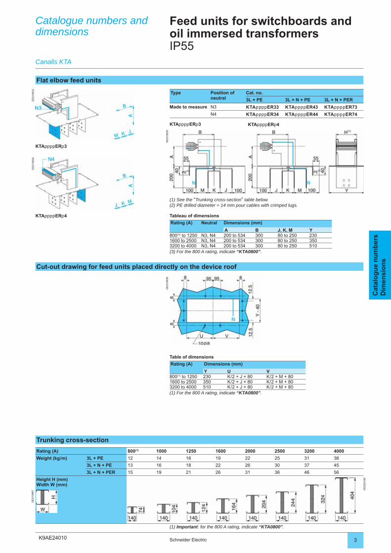
K9AE24010
DD
2108
33
DD
2108
35
DD
2108
34
DD
2108
36
3Schneider Electric
Cat
alo
gu
e n
um
ber
sD
imen
sio
ns
Flat elbow feed units
Type Position of neutral
Cat. no.
3L + PE 3L + N + PE 3L + N + PER
Made to measure N3 KTAppppER33 KTAppppER43 KTAppppER73
N4 KTAppppER34 KTAppppER44 KTAppppER74
KTAppppERp3
(1) See the “Trunking cross-section” table below.(2) PE drilled diameter = 14 mm pour cables with crimped lugs.
Tableau of dimensions
Rating (A) Neutral Dimensions (mm)
A B J, K, M Y800(3) to 1250 N3, N4 200 to 534 300 80 to 250 2301600 to 2500 N3, N4 200 to 534 300 80 to 250 3503200 to 4000 N3, N4 200 to 534 300 80 to 250 510(3) For the 800 A rating, indicate “KTA0800”.
KTAppppERp3
KTAppppERp4
Catalogue numbers and dimensions
Canalis KTA
Feed units for switchboards and oil immersed transformersIP55
Cut-out drawing for feed units placed directly on the device roof
Table of dimensions
Rating (A) Dimensions (mm)
Y U V800(1) to 1250 230 K / 2 + J + 80 K / 2 + M + 801600 to 2500 350 K / 2 + J + 80 K / 2 + M + 803200 to 4000 510 K / 2 + J + 80 K / 2 + M + 80(1) For the 800 A rating, indicate “KTA0800”.
KTAppppERp4
Trunking cross-section
Rating (A) 800(1) 1000 1250 1600 2000 2500 3200 4000
Weight (kg / m) 3L + PE 12 14 16 19 22 25 31 38
3L + N + PE 13 16 18 22 26 30 37 45
3L + N + PER 15 19 21 26 31 36 46 56
Height H (mm)Width W (mm)
DD
2021
80
DD
2108
67
(1) Important: for the 800 A rating, indicate “KTA0800”.
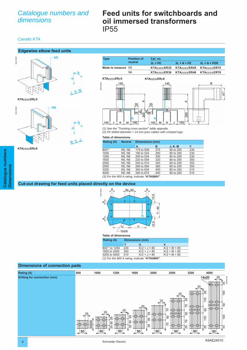
K9AE24010
DD
2108
39
DD
2108
37D
D21
0838
DD
2108
36
4 Schneider Electric
Cat
alo
gu
e n
um
ber
sD
imen
sio
ns
Edgewise elbow feed units
Type Position of neutral
Cat. no.
3L + PE 3L + N + PE 3L + N + PER
Made to measure N5 KTAppppER35 KTAppppER45 KTAppppER75
N6 KTAppppER36 KTAppppER46 KTAppppER76
KTAppppERp5
KTAppppERp5
KTAppppERp6
(1) See the “Trunking cross-section” table opposite.(2) PE drilled diameter = 14 mm pour cables with crimped lugs.
Table of dimensions
Rating (A) Neutral Dimensions (mm)
A B J, K, M Y800(3) N5, N6 175 to 509 275 80 to 250 2301000 N5, N6 190 to 524 290 80 to 250 2301250 N5, N6 200 to 534 300 80 to 250 2301600 N5, N6 220 to 554 320 80 to 250 3502000 N5, N6 240 to 574 340 80 to 250 3502500 N5, N6 260 to 594 360 80 to 250 3503200 N5, N6 300 to 634 400 80 to 250 5104000 N5, N6 340 to 674 440 80 to 250 510(3) For the 800 A rating, indicate “KTA0800”.
Cut-out drawing for feed units placed directly on the device
Table of dimensions
Rating (A) Dimensions (mm)
Y U V800(1) to 1250 230 K / 2 + J + 80 K / 2 + M + 801600 to 2500 350 K / 2 + J + 80 K / 2 + M + 803200 to 4000 510 K / 2 + J + 80 K / 2 + M + 80(1) For the 800 A rating, indicate “KTA0800”.
Catalogue numbers and dimensions
Canalis KTA
Feed units for switchboards and oil immersed transformersIP55
KTAppppERp6
Dimensions of connection pads
Rating (A) 800 1000 1250 1600 2000 2500 3200 4000
Drilling for connection (mm)
DD
2021
82
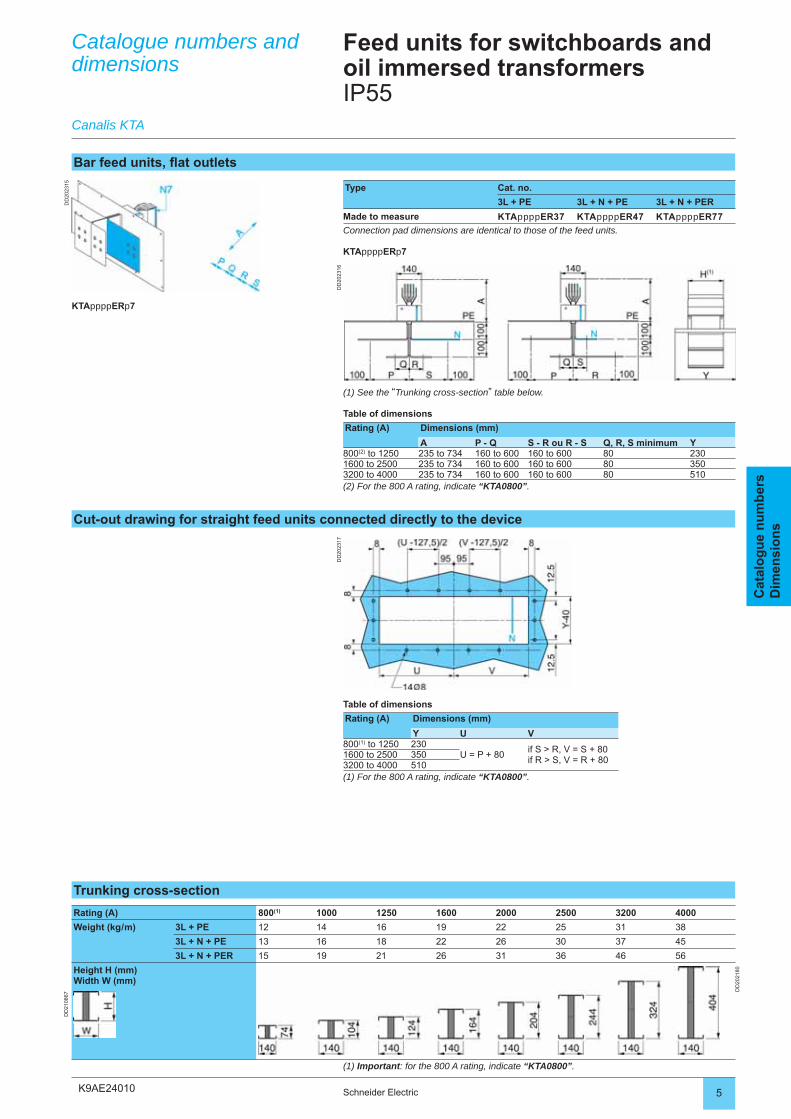
K9AE24010
DD
2023
16
DD
2023
15
DD
2023
17
5Schneider Electric
Cat
alo
gu
e n
um
ber
sD
imen
sio
ns
Catalogue numbers and dimensions
Canalis KTA
Feed units for switchboards and oil immersed transformersIP55
Bar feed units, fl at outlets
Type Cat. no.
3L + PE 3L + N + PE 3L + N + PER
Made to measure KTAppppER37 KTAppppER47 KTAppppER77
Connection pad dimensions are identical to those of the feed units.
KTAppppERp7
KTAppppERp7
(1) See the “Trunking cross-section” table below.
Table of dimensions
Rating (A) Dimensions (mm)
A P - Q S - R ou R - S Q, R, S minimum Y800(2) to 1250 235 to 734 160 to 600 160 to 600 80 2301600 to 2500 235 to 734 160 to 600 160 to 600 80 3503200 to 4000 235 to 734 160 to 600 160 to 600 80 510(2) For the 800 A rating, indicate “KTA0800”.
Cut-out drawing for straight feed units connected directly to the device
Table of dimensions
Rating (A) Dimensions (mm)
Y U V800(1) to 1250 230
U = P + 80if S > R, V = S + 80if R > S, V = R + 80
1600 to 2500 3503200 to 4000 510(1) For the 800 A rating, indicate “KTA0800”.
Trunking cross-section
Rating (A) 800(1) 1000 1250 1600 2000 2500 3200 4000
Weight (kg / m) 3L + PE 12 14 16 19 22 25 31 38
3L + N + PE 13 16 18 22 26 30 37 45
3L + N + PER 15 19 21 26 31 36 46 56
Height H (mm)Width W (mm)
DD
2021
80
DD
2108
67
(1) Important: for the 800 A rating, indicate “KTA0800”.
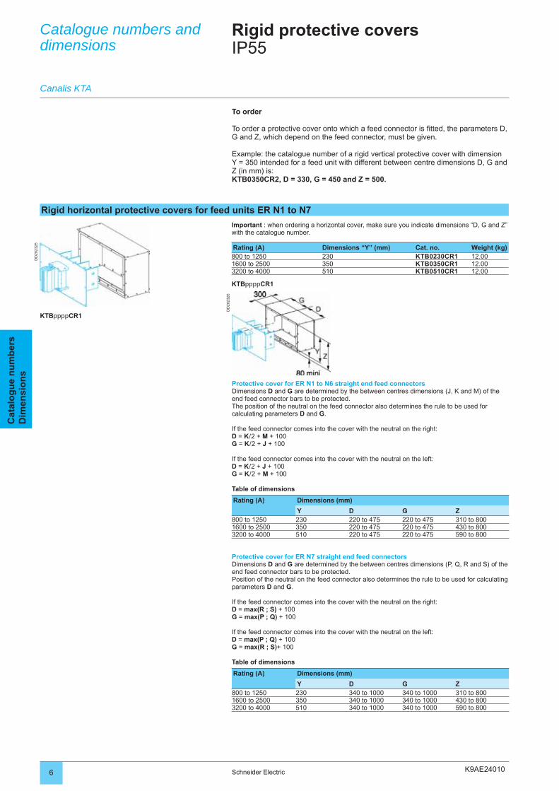
K9AE24010
DD
2023
26
DD
2023
25
6 Schneider Electric
Cat
alo
gu
e n
um
ber
sD
imen
sio
ns
Rigid horizontal protective covers for feed units ER N1 to N7
Important : when ordering a horizontal cover, make sure you indicate dimensions “D, G and Z” with the catalogue number.
Rating (A) Dimensions “Y” (mm) Cat. no. Weight (kg)800 to 1250 230 KTB0230CR1 12.001600 to 2500 350 KTB0350CR1 12.003200 to 4000 510 KTB0510CR1 12.00
KTBppppCR1
KTBppppCR1
Protective cover for ER N1 to N6 straight end feed connectorsDimensions D and G are determined by the between centres dimensions (J, K and M) of the end feed connector bars to be protected.The position of the neutral on the feed connector also determines the rule to be used for calculating parameters D and G.
If the feed connector comes into the cover with the neutral on the right:D = K / 2 + M + 100G = K / 2 + J + 100
If the feed connector comes into the cover with the neutral on the left:D = K / 2 + J + 100G = K / 2 + M + 100
Table of dimensions
Rating (A) Dimensions (mm)
Y D G Z800 to 1250 230 220 to 475 220 to 475 310 to 8001600 to 2500 350 220 to 475 220 to 475 430 to 8003200 to 4000 510 220 to 475 220 to 475 590 to 800
Protective cover for ER N7 straight end feed connectorsDimensions D and G are determined by the between centres dimensions (P, Q, R and S) of the end feed connector bars to be protected.Position of the neutral on the feed connector also determines the rule to be used for calculating parameters D and G.
If the feed connector comes into the cover with the neutral on the right:D = max(R ; S) + 100G = max(P ; Q) + 100
If the feed connector comes into the cover with the neutral on the left:D = max(P ; Q) + 100G = max(R ; S)+ 100
Table of dimensions
Rating (A) Dimensions (mm)
Y D G Z800 to 1250 230 340 to 1000 340 to 1000 310 to 8001600 to 2500 350 340 to 1000 340 to 1000 430 to 8003200 to 4000 510 340 to 1000 340 to 1000 590 to 800
Catalogue numbers and dimensions
Canalis KTA
Rigid protective coversIP55
To order
To order a protective cover onto which a feed connector is fi tted, the parameters D, G and Z, which depend on the feed connector, must be given.
Example: the catalogue number of a rigid vertical protective cover with dimension Y = 350 intended for a feed unit with different between centre dimensions D, G and Z (in mm) is:KTB0350CR2, D = 330, G = 450 and Z = 500.
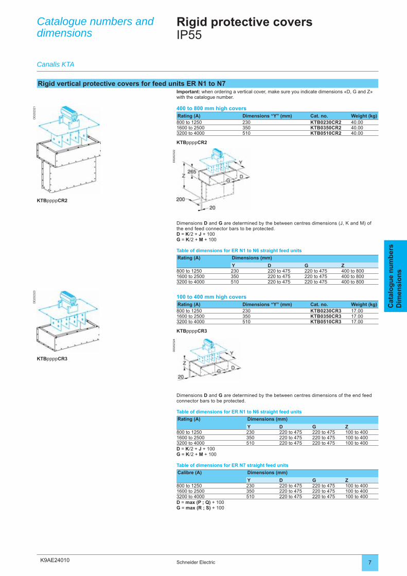
K9AE24010
DD
2023
22
DD
2023
21
DD
2023
24
DD
2023
23
7Schneider Electric
Cat
alo
gu
e n
um
ber
sD
imen
sio
ns
Rigid vertical protective covers for feed units ER N1 to N7Important: when ordering a vertical cover, make sure you indicate dimensions «D, G and Z» with the catalogue number.
400 to 800 mm high coversRating (A) Dimensions “Y” (mm) Cat. no. Weight (kg)800 to 1250 230 KTB0230CR2 40.001600 to 2500 350 KTB0350CR2 40.003200 to 4000 510 KTB0510CR2 40.00
KTBppppCR2
Dimensions D and G are determined by the between centres dimensions (J, K and M) of the end feed connector bars to be protected.D = K / 2 + J + 100G = K / 2 + M + 100
Table of dimensions for ER N1 to N6 straight feed units
Rating (A) Dimensions (mm)
Y D G Z800 to 1250 230 220 to 475 220 to 475 400 to 8001600 to 2500 350 220 to 475 220 to 475 400 to 8003200 to 4000 510 220 to 475 220 to 475 400 to 800
100 to 400 mm high coversRating (A) Dimensions “Y” (mm) Cat. no. Weight (kg)800 to 1250 230 KTB0230CR3 17.001600 to 2500 350 KTB0350CR3 17.003200 to 4000 510 KTB0510CR3 17.00
KTBppppCR3
Catalogue numbers and dimensions
Canalis KTA
Rigid protective coversIP55
KTBppppCR2
KTBppppCR3
Dimensions D and G are determined by the between centres dimensions of the end feed connector bars to be protected.
Table of dimensions for ER N1 to N6 straight feed units
Rating (A) Dimensions (mm)
Y D G Z800 to 1250 230 220 to 475 220 to 475 100 to 4001600 to 2500 350 220 to 475 220 to 475 100 to 4003200 to 4000 510 220 to 475 220 to 475 100 to 400D = K / 2 + J + 100G = K / 2 + M + 100
Table of dimensions for ER N7 straight feed units
Calibre (A) Dimensions (mm)
Y D G Z800 to 1250 230 220 to 475 220 to 475 100 to 4001600 to 2500 350 220 to 475 220 to 475 100 to 4003200 to 4000 510 220 to 475 220 to 475 100 to 400D = max (P ; Q) + 100G = max (R ; S) + 100
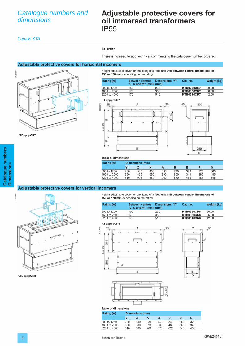
K9AE24010
DD
2028
72
DD
2028
71D
D20
2869
DD
2028
70
8 Schneider Electric
Cat
alo
gu
e n
um
ber
sD
imen
sio
ns
Adjustable protective covers for horizontal incomers
Height adjustable cover for the fi tting of a feed unit with between centre dimensions of 150 or 170 mm depending on the rating.
Rating (A) Between centres “J, K and M” (mm)
Dimensions “Y” (mm)
Cat. no. Weight (kg)
800 to 1250 150 230 KTB0230CR7 30.001600 to 2500 170 350 KTB0350CR7 36.003200 to 4000 170 510 KTB0510CR7 42.00
KTBppppCR7
Table of dimensions
Rating (A) Dimensions (mm)
Y Z X A B E F G800 to 1250 230 565 450 830 740 320 125 3651600 to 2500 350 825 650 890 800 340 265 4853200 to 4000 510 905 650 960 870 450 185 645
Catalogue numbers and dimensions
Canalis KTA
Adjustable protective covers for oil immersed transformersIP55
KTBppppCR7
To order
There is no need to add technical comments to the catalogue number ordered.
Adjustable protective covers for vertical incomers
Height adjustable cover for the fi tting of a feed unit with between centre dimensions of 150 or 170 mm depending on the rating.
Rating (A) Between centres “J, K and M” (mm)
Dimensions “Y” (mm)
Cat. no. Weight (kg)
800 to 1250 150 230 KTB0230CR8 30.001600 to 2500 170 350 KTB0350CR8 36.003200 to 4000 170 510 KTB0510CR8 42.00
KTBppppCR8
Table of dimensions
Rating (A) Dimensions (mm)
Y Z A B C D E800 to 1250 230 600 830 740 340 260 3201600 to 2500 350 600 890 800 460 380 3403200 to 4000 510 600 960 870 620 540 450
KTBppppCR8
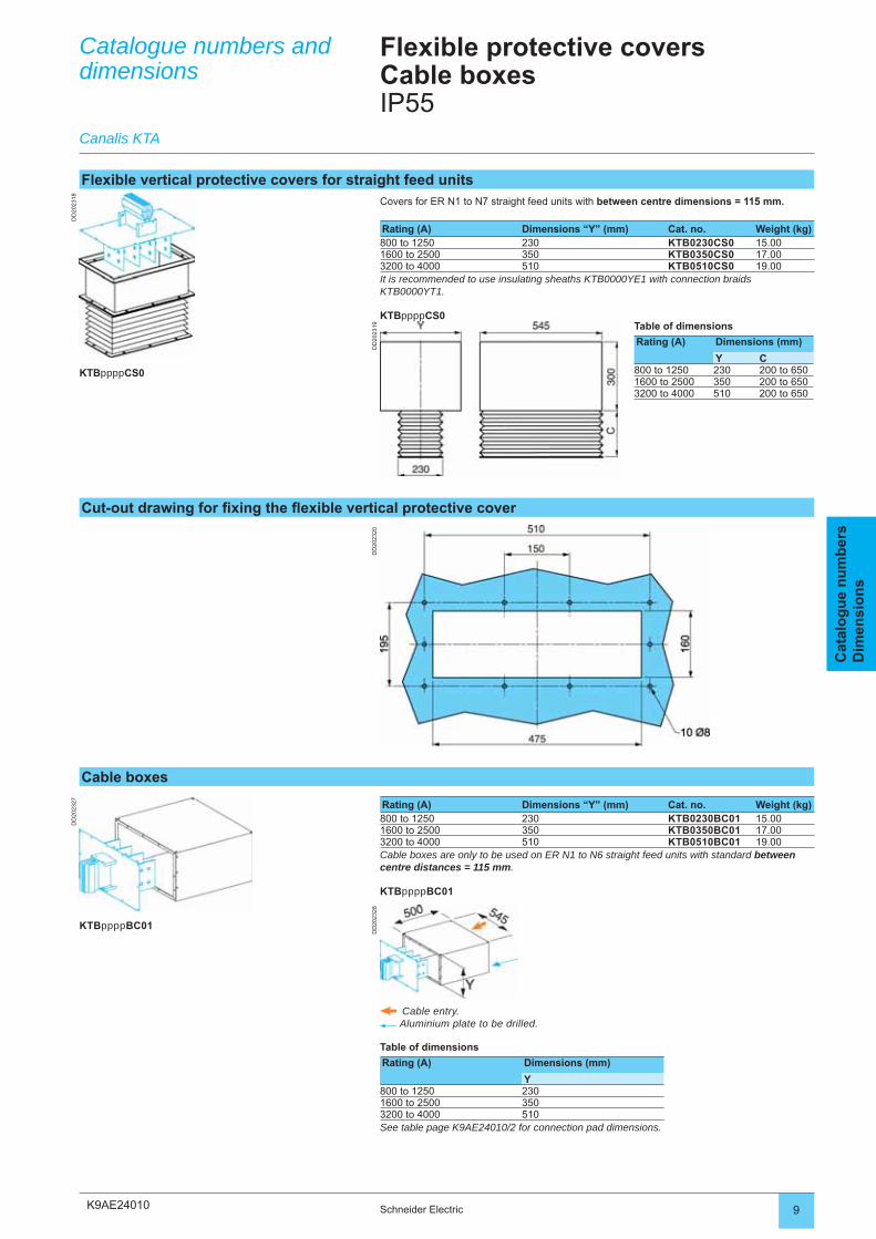
K9AE24010
DD
2023
28
DD
2023
27
DD
2023
19
DD
2023
18
DD
2023
20
9Schneider Electric
Cat
alo
gu
e n
um
ber
sD
imen
sio
ns
Cable boxes
Rating (A) Dimensions “Y” (mm) Cat. no. Weight (kg)800 to 1250 230 KTB0230BC01 15.001600 to 2500 350 KTB0350BC01 17.003200 to 4000 510 KTB0510BC01 19.00Cable boxes are only to be used on ER N1 to N6 straight feed units with standard between centre distances = 115 mm.
KTBppppBC01
Cable entry. Aluminium plate to be drilled.
Table of dimensions
Rating (A) Dimensions (mm)
Y800 to 1250 2301600 to 2500 3503200 to 4000 510See table page K9AE24010/2 for connection pad dimensions.
Catalogue numbers and dimensions
Canalis KTA
Flexible protective covers Cable boxesIP55
KTBppppBC01
Flexible vertical protective covers for straight feed unitsCovers for ER N1 to N7 straight feed units with between centre dimensions = 115 mm.
Rating (A) Dimensions “Y” (mm) Cat. no. Weight (kg)800 to 1250 230 KTB0230CS0 15.001600 to 2500 350 KTB0350CS0 17.003200 to 4000 510 KTB0510CS0 19.00It is recommended to use insulating sheaths KTB0000YE1 with connection braids KTB0000YT1.
KTBppppCS0
KTBppppCS0
Table of dimensions
Rating (A) Dimensions (mm)
Y C800 to 1250 230 200 to 6501600 to 2500 350 200 to 6503200 to 4000 510 200 to 650
Cut-out drawing for fi xing the fl exible vertical protective cover
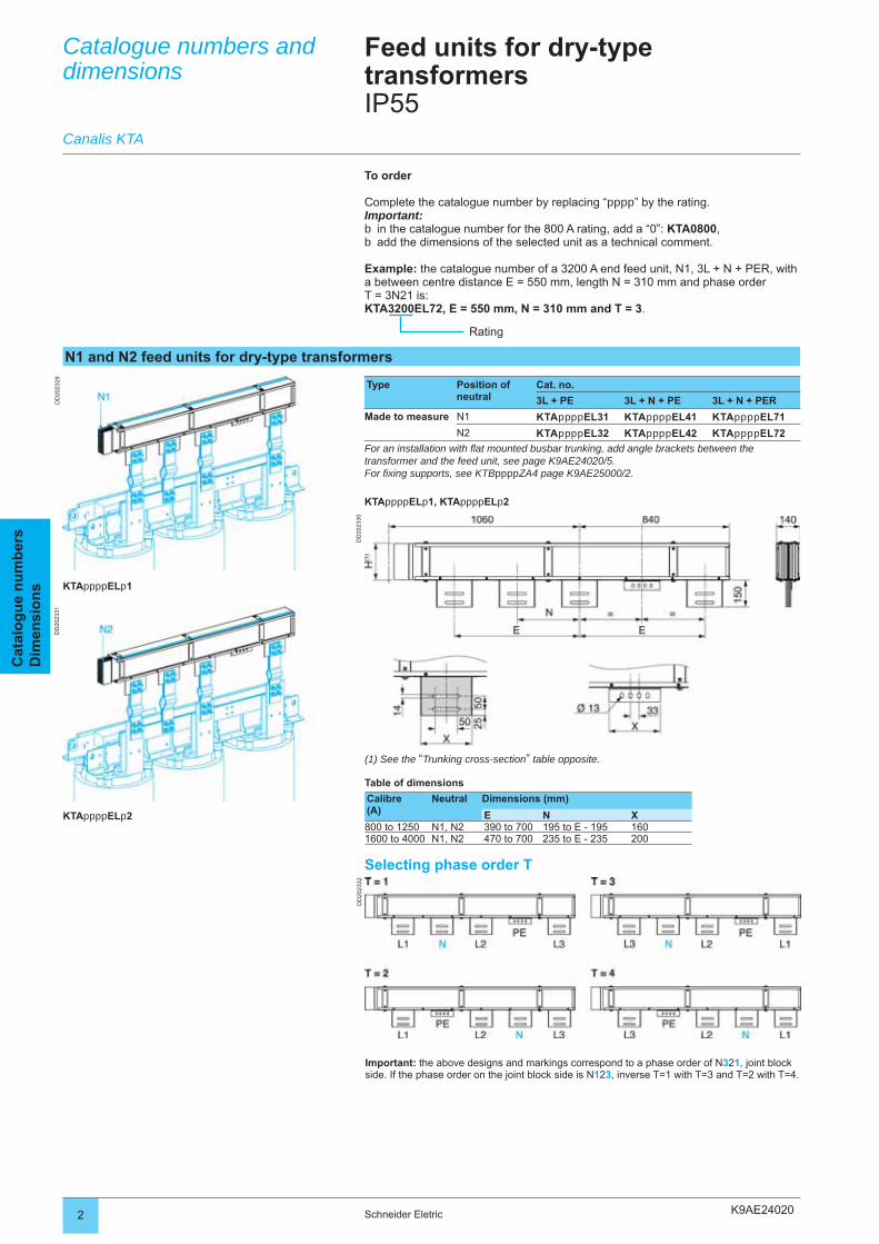
K9AE24020
DD
2023
29
DD
2023
30
DD
2023
31
DD
2023
32
2 Schneider Eletric
Cat
alo
gu
e n
um
ber
sD
imen
sio
ns
Catalogue numbers and dimensions
Feed units for dry-type transformersIP55
N1 and N2 feed units for dry-type transformers
Type Position of neutral
Cat. no.
3L + PE 3L + N + PE 3L + N + PER
Made to measure N1 KTAppppEL31 KTAppppEL41 KTAppppEL71
N2 KTAppppEL32 KTAppppEL42 KTAppppEL72
For an installation with fl at mounted busbar trunking, add angle brackets between the transformer and the feed unit, see page K9AE24020/5.For fi xing supports, see KTBppppZA4 page K9AE25000/2.
KTAppppELp1, KTAppppELp2
To order
Complete the catalogue number by replacing “pppp” by the rating.Important:
in the catalogue number for the 800 A rating, add a “0”: KTA0800,add the dimensions of the selected unit as a technical comment.
Example: the catalogue number of a 3200 A end feed unit, N1, 3L + N + PER, with a between centre distance E = 550 mm, length N = 310 mm and phase orderT = 3N21 is:KTA3200EL72, E = 550 mm, N = 310 mm and T = 3.
bb
Rating
(1) See the “Trunking cross-section” table opposite.
Table of dimensions
Calibre(A)
Neutral Dimensions (mm)
E N X800 to 1250 N1, N2 390 to 700 195 to E - 195 1601600 to 4000 N1, N2 470 to 700 235 to E - 235 200
Selecting phase order T
KTAppppELp1
Canalis KTA
KTAppppELp2
Important: the above designs and markings correspond to a phase order of N321, joint block side. If the phase order on the joint block side is N123, inverse T=1 with T=3 and T=2 with T=4.
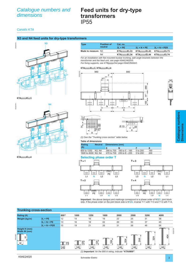
K9AE24020
DD
2023
33
DD
2023
35
DD
2023
34
DD
2023
36
3Schneider Eletric
Cat
alo
gu
e n
um
ber
sD
imen
sio
ns
N3 and N4 feed units for dry-type transformers
Type Position of neutral
Cat. no.
3L + PE 3L + N + PE 3L + N + PER
Made to measure N3 KTAppppEL33 KTAppppEL43 KTAppppEL73
N4 KTAppppEL34 KTAppppEL44 KTAppppEL74
For an installation with fl at mounted busbar trunking, add angle brackets between the transformer and the feed unit, see page K9AE24020/5.For fi xing supports, see KTBppppZA4 page K9AE25000/2.
KTAppppELp3, KTAppppELp4
(1) See the “Trunking cross-section” table below.
Table of dimensions
Rating(A)
Neutral Dimensions (mm)
E N F X800 to 1250 N3, N4 390 to 700 195 to E - 195 0 to 200 1601600 to 4000 N3, N4 470 to 700 235 to E - 235 0 to 200 200
Selecting phase order T
KTAppppELp3
KTAppppELp4
Catalogue numbers and dimensions
Canalis KTA
Feed units for dry-type transformersIP55
Trunking cross-section
Rating (A) 800(1) 1000 1250 1600 2000 2500 3200 4000
Weight (kg / m) 3L + PE 12 14 16 19 22 25 31 38
3L + N + PE 13 16 18 22 26 30 37 45
3L + N + PER 15 19 21 26 31 36 46 56
Height H (mm)Width W (mm)
DD
2021
80
DD
2108
67
(1) Important: for the 800 A rating, indicate “KTA0800”.
Important : the above designs and markings correspond to a phase order of N321, joint block side. If the phase order on the joint block side is N123, inverse T=1 with T=3 and T=2 with T=4.
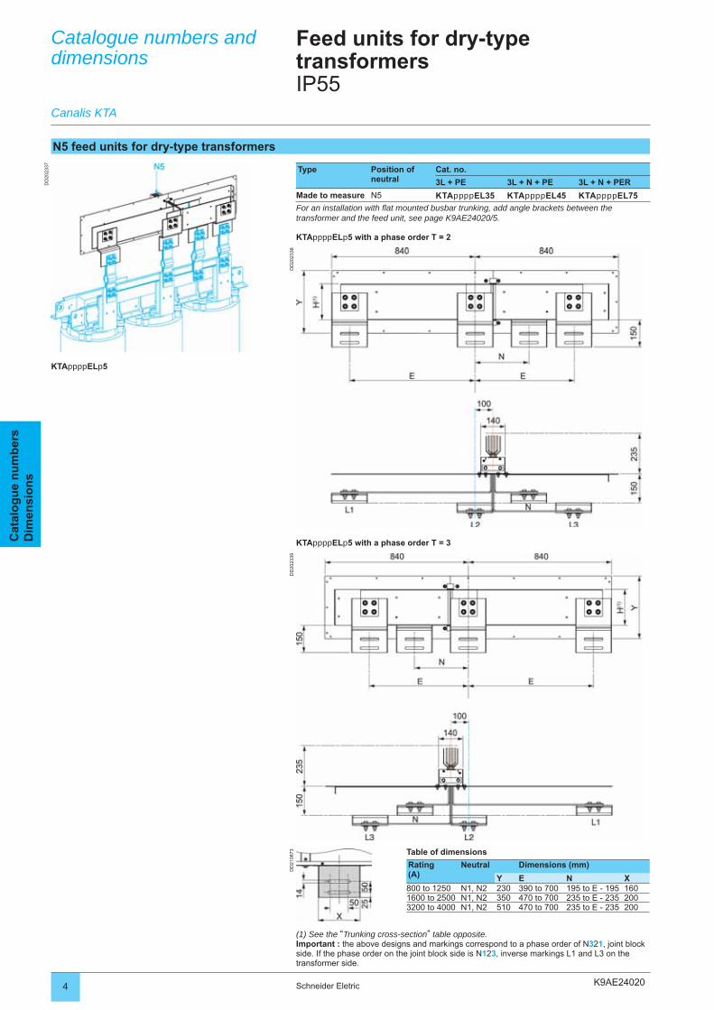
K9AE24020
DD
2023
38
DD
2023
37
DD
2023
39D
D21
0873
4 Schneider Eletric
Cat
alo
gu
e n
um
ber
sD
imen
sio
ns
N5 feed units for dry-type transformers
Type Position of neutral
Cat. no.
3L + PE 3L + N + PE 3L + N + PER
Made to measure N5 KTAppppEL35 KTAppppEL45 KTAppppEL75
For an installation with fl at mounted busbar trunking, add angle brackets between the transformer and the feed unit, see page K9AE24020/5.
KTAppppELp5 with a phase order T = 2
KTAppppELp5
(1) See the “Trunking cross-section” table opposite.Important : the above designs and markings correspond to a phase order of N321, joint block side. If the phase order on the joint block side is N123, inverse markings L1 and L3 on the transformer side.
Catalogue numbers and dimensions
Canalis KTA
Feed units for dry-type transformersIP55
KTAppppELp5 with a phase order T = 3
Table of dimensions
Rating(A)
Neutral Dimensions (mm)
Y E N X800 to 1250 N1, N2 230 390 to 700 195 to E - 195 1601600 to 2500 N1, N2 350 470 to 700 235 to E - 235 2003200 to 4000 N1, N2 510 470 to 700 235 to E - 235 200
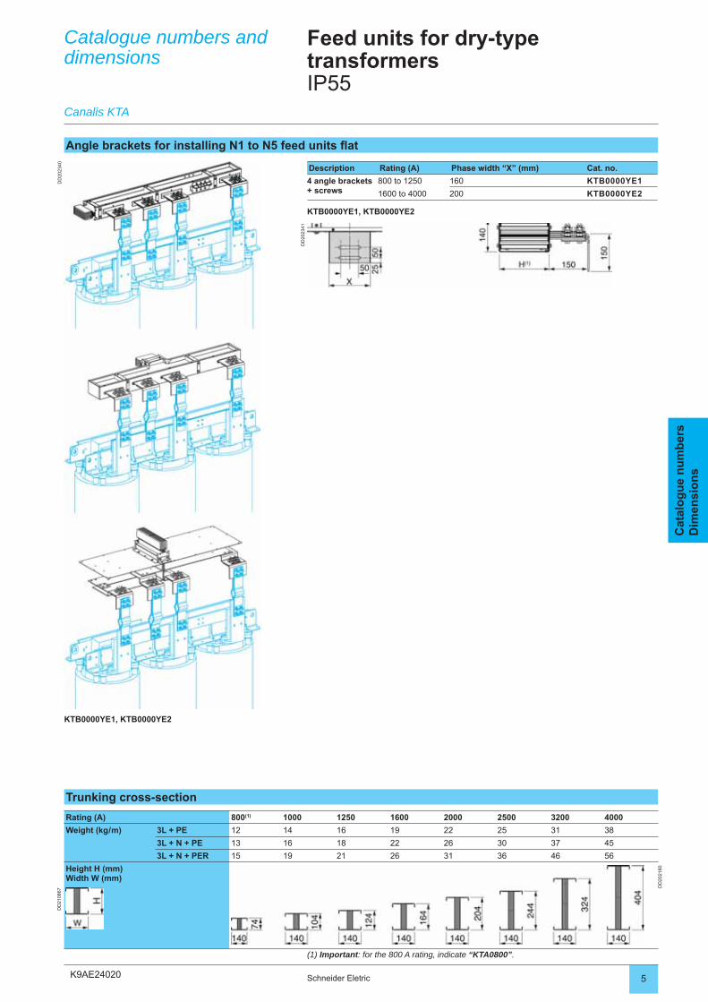
K9AE24020
DD
2023
40
DD
2023
41
5Schneider Eletric
Cat
alo
gu
e n
um
ber
sD
imen
sio
ns
Catalogue numbers and dimensions
Canalis KTA
Feed units for dry-type transformersIP55
Angle brackets for installing N1 to N5 feed units fl at
Description Rating (A) Phase width “X” (mm) Cat. no.
4 angle brackets + screws
800 to 1250 160 KTB0000YE1
1600 to 4000 200 KTB0000YE2
KTB0000YE1, KTB0000YE2
KTB0000YE1, KTB0000YE2
Trunking cross-section
Rating (A) 800(1) 1000 1250 1600 2000 2500 3200 4000
Weight (kg / m) 3L + PE 12 14 16 19 22 25 31 38
3L + N + PE 13 16 18 22 26 30 37 45
3L + N + PER 15 19 21 26 31 36 46 56
Height H (mm)Width W (mm)
DD
2021
80
DD
2108
67
(1) Important: for the 800 A rating, indicate “KTA0800”.
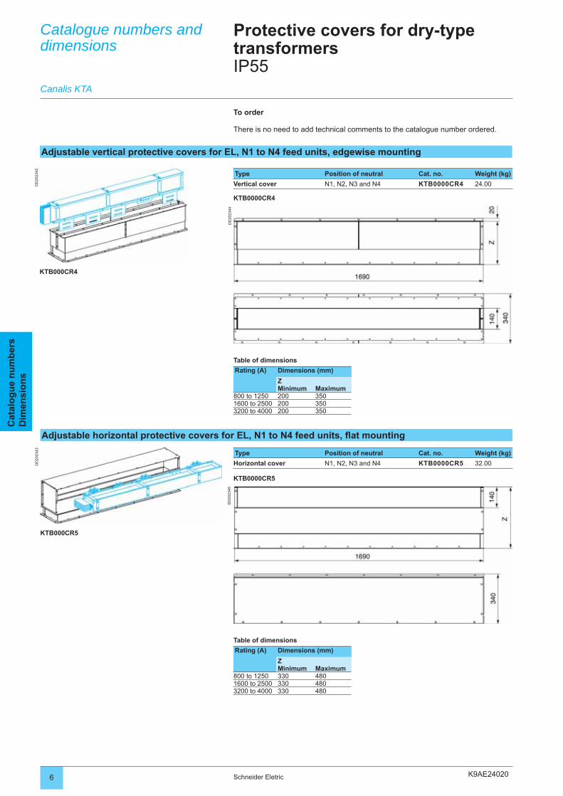
K9AE24020
DD
2023
42
DD
2023
44
DD
2023
43
DD
2023
45
6 Schneider Eletric
Cat
alo
gu
e n
um
ber
sD
imen
sio
ns
Protective covers for dry-type transformersIP55
Table of dimensions
Rating (A) Dimensions (mm)
ZMinimum Maximum
800 to 1250 200 3501600 to 2500 200 3503200 to 4000 200 350
Type Position of neutral Cat. no. Weight (kg)
Horizontal cover N1, N2, N3 and N4 KTB0000CR5 32.00
KTB0000CR5
KTB000CR5
Table of dimensions
Rating (A) Dimensions (mm)
ZMinimum Maximum
800 to 1250 330 4801600 to 2500 330 4803200 to 4000 330 480
Catalogue numbers and dimensions
Adjustable vertical protective covers for EL, N1 to N4 feed units, edgewise mounting
Canalis KTA
Type Position of neutral Cat. no. Weight (kg)
Vertical cover N1, N2, N3 and N4 KTB0000CR4 24.00
KTB0000CR4
KTB000CR4
To order
There is no need to add technical comments to the catalogue number ordered.
Adjustable horizontal protective covers for EL, N1 to N4 feed units, fl at mounting
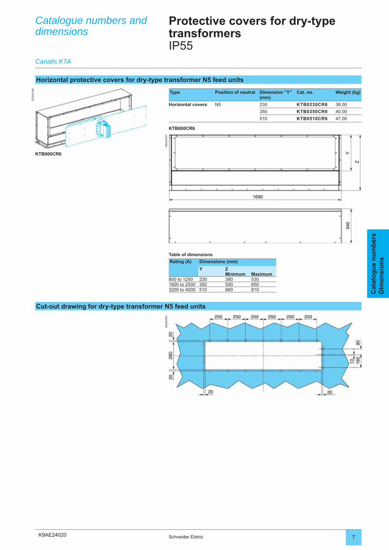
K9AE24020
DD
2023
46
DD
2023
47D
D20
2501
7Schneider Eletric
Cat
alo
gu
e n
um
ber
sD
imen
sio
ns
Catalogue numbers and dimensions
Canalis KTA
Protective covers for dry-type transformersIP55
Horizontal protective covers for dry-type transformer N5 feed units
Type Position of neutral Dimension “Y” (mm)
Cat. no. Weight (kg)
Horizontal covers N5 230 KTB0230CR6 38.00
350 KTB0350CR6 40.00
510 KTB0510CR6 47.00
KTB000CR6
KTB000CR6
Cut-out drawing for dry-type transformer N5 feed units
Table of dimensions
Rating (A) Dimensions (mm)
Y ZMinimum Maximum
800 to 1250 230 380 5301600 to 2500 350 500 6503200 to 4000 510 660 810
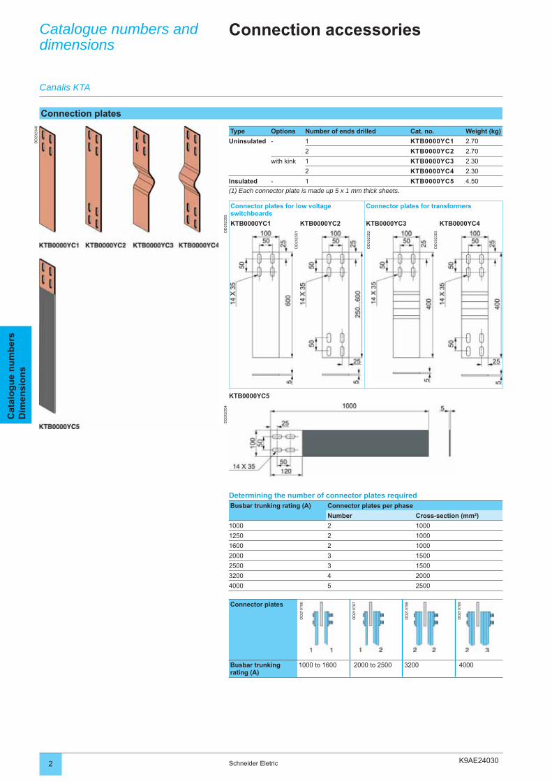
K9AE24030
DD
2023
48
DD
2023
50D
D20
2354
2 Schneider Eletric
Cat
alo
gu
e n
um
ber
sD
imen
sio
ns
Catalogue numbers and dimensions
Connection accessories
Connection plates
Type Options Number of ends drilled Cat. no. Weight (kg)
Uninsulated - 1 KTB0000YC1 2.70
2 KTB0000YC2 2.70
with kink 1 KTB0000YC3 2.30
2 KTB0000YC4 2.30
Insulated - 1 KTB0000YC5 4.50
(1) Each connector plate is made up 5 x 1 mm thick sheets.
Connector plates for low voltage switchboards
Connector plates for transformers
KTB0000YC1 KTB0000YC2 KTB0000YC3 KTB0000YC4
DD
2023
51
DD
2023
52
DD
2023
53
KTB0000YC5
Canalis KTA
Determining the number of connector plates requiredBusbar trunking rating (A) Connector plates per phase
Number Cross-section (mm2)
1000 2 1000
1250 2 1000
1600 2 1000
2000 3 1500
2500 3 1500
3200 4 2000
4000 5 2500
Connector plates
DD
2107
86
DD
2107
87
DD
2107
88
DD
2107
89
Busbar trunking rating (A)
1000 to 1600 2000 to 2500 3200 4000
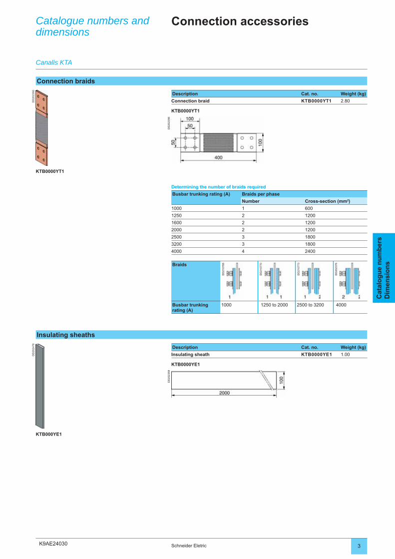
K9AE24030
DD
2023
55
DD
2023
56
DD
2024
78
DD
2023
58
3Schneider Eletric
Cat
alo
gu
e n
um
ber
sD
imen
sio
ns
Connection accessories
Description Cat. no. Weight (kg)
Connection braid KTB0000YT1 2.80
KTB0000YT1
KTB0000YT1
Catalogue numbers and dimensions
Canalis KTA
Determining the number of braids required
Busbar trunking rating (A) Braids per phase
Number Cross-section (mm2)
1000 1 600
1250 2 1200
1600 2 1200
2000 2 1200
2500 3 1800
3200 3 1800
4000 4 2400
Braids
DD
2107
68
DD
2107
70
DD
2107
73
DD
2023
76
Busbar trunking rating (A)
1000 1250 to 2000 2500 to 3200 4000
Connection braids
Insulating sheaths
Description Cat. no. Weight (kg)
Insulating sheath KTB0000YE1 1.00
KTB0000YE1
KTB000YE1
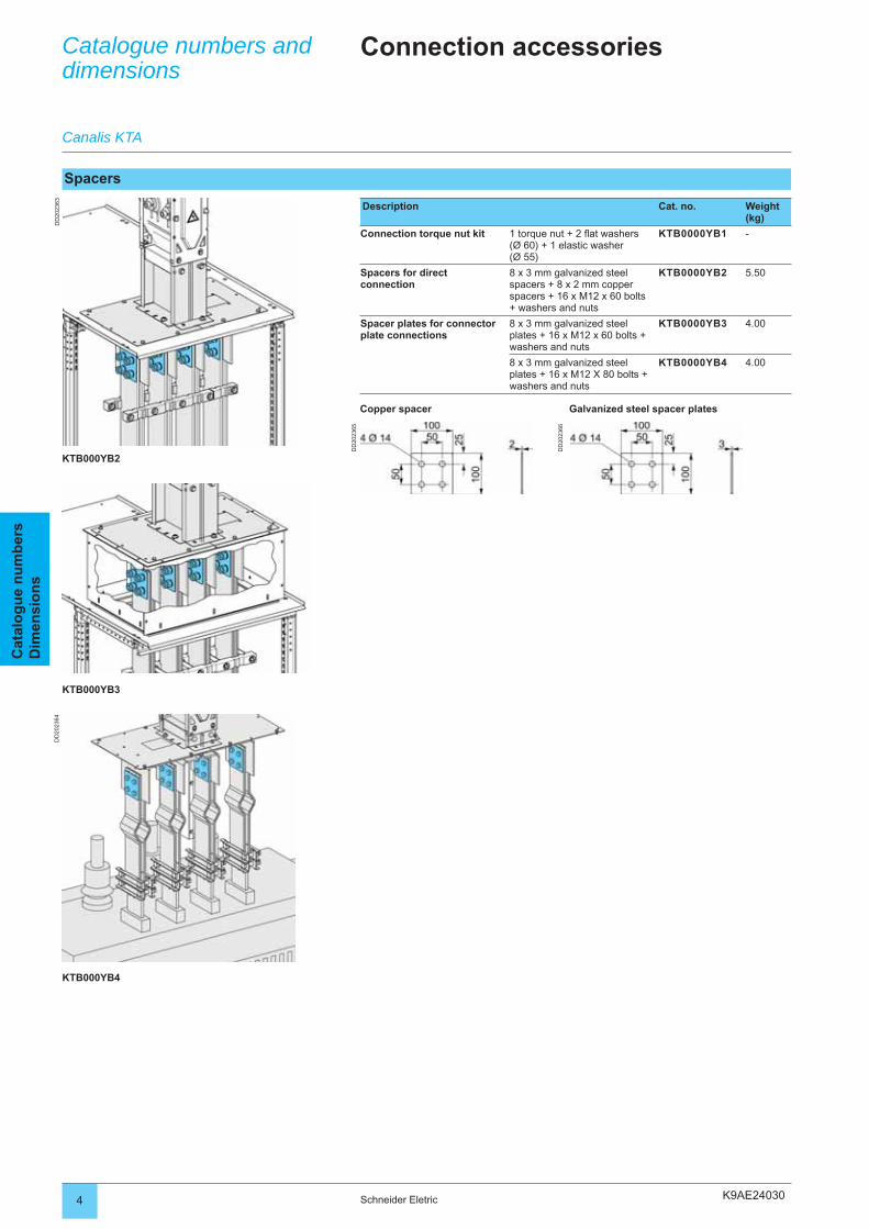
K9AE24030
DD
2023
63
DD
2023
65
DD
2023
64
DD
2023
66
4 Schneider Eletric
Cat
alo
gu
e n
um
ber
sD
imen
sio
ns
Catalogue numbers and dimensions
Connection accessories
Canalis KTA
Spacers
Description Cat. no. Weight (kg)
Connection torque nut kit 1 torque nut + 2 fl at washers (Ø 60) + 1 elastic washer (Ø 55)
KTB0000YB1 -
Spacers for direct connection
8 x 3 mm galvanized steel spacers + 8 x 2 mm copper spacers + 16 x M12 x 60 bolts + washers and nuts
KTB0000YB2 5.50
Spacer plates for connector plate connections
8 x 3 mm galvanized steel plates + 16 x M12 x 60 bolts + washers and nuts
KTB0000YB3 4.00
8 x 3 mm galvanized steel plates + 16 x M12 X 80 bolts + washers and nuts
KTB0000YB4 4.00
Copper spacer Galvanized steel spacer plates
KTB000YB2
KTB000YB3
KTB000YB4
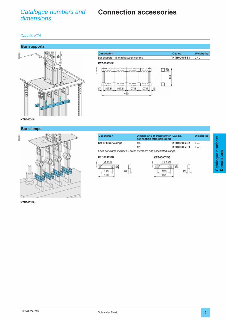
K9AE24030
DD
2023
59
DD
2023
60
DD
2023
61
DD
2023
62
DD
2025
00
5Schneider Eletric
Cat
alo
gu
e n
um
ber
sD
imen
sio
ns
Bar supports
Description Cat. no. Weight (kg)
Bar support, 115 mm between centres KTB0000YS1 2.40
KTB0000YS1
KTB000YS1
Bar clamps
Description Dimensions of transformer connection terminals (mm)
Cat. no. Weight (kg)
Set of 8 bar clamps 100 KTB0000YS2 6.40
120 KTB0000YS3 6.40
Each bar clamp includes 2 cross members and associated fi xings.
KTB0000YS2 KTB0000YS3
KTB000YSp
Catalogue numbers and dimensions
Connection accessories
Canalis KTA
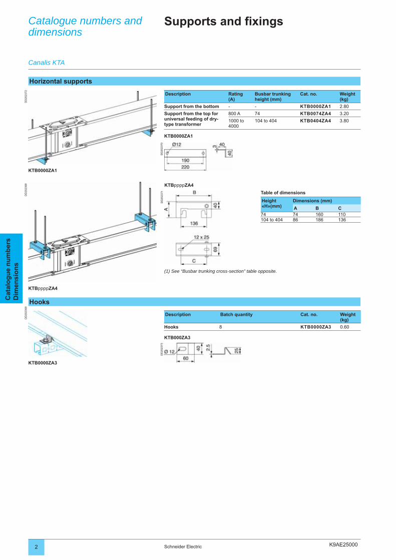
K9AE25000
DD
2023
68D
D20
2369
DD
2023
70D
D20
2371
DD
2023
72
DD
2023
73
2 Schneider Electric
Cat
alo
gu
e n
um
ber
sD
imen
sio
ns
Catalogue numbers and dimensions
Supports and fixings
Horizontal supports
Description Rating(A)
Busbar trunking height (mm)
Cat. no. Weight (kg)
Support from the bottom - - KTB0000ZA1 2.80
Support from the top for universal feeding of dry-type transformer
800 A 74 KTB0074ZA4 3.20
1000 to 4000
104 to 404 KTB0404ZA4 3.80
KTB0000ZA1
KTBppppZA4
Canalis KTA
Hooks
Description Batch quantity Cat. no. Weight (kg)
Hooks 8 KTB0000ZA3 0.60
KTB000ZA3
KTB0000ZA3
KTB0000ZA1
KTBppppZA4
(1) See “Busbar trunking cross-section” table opposite.
Table of dimensions
Height «H»(mm)
Dimensions (mm)
A B C74 74 160 110104 to 404 86 186 136
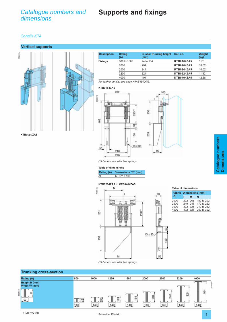
K9AE25000
DD
2023
74
DD
2023
75D
D20
2499
3Schneider Electric
Cat
alo
gu
e n
um
ber
sD
imen
sio
ns
Catalogue numbers and dimensions
Supports and fixings
Vertical supports
Description Rating(A)
Busbar trunking height (mm)
Cat. no. Weight (kg)
Fixings 800 to 1600 74 to 164 KTB0164ZA5 5.75
2000 204 KTB0204ZA5 10.02
2500 244 KTB0244ZA5 10.62
3200 324 KTB0324ZA5 11.82
4000 404 KTB0404ZA5 12.58
For further details, see page K9AE45000/2.
KTB0164ZA5
Canalis KTA
Trunking cross-section
Rating (A) 800 1000 1250 1600 2000 2500 3200 4000
Height H (mm)Width W (mm)
DD
2021
80
DD
2108
67
(1) Dimensions with free springs.
Table of dimensions
Rating (A) Dimensions “Y” (mm)
All 50 < Y < 100
KTB0204ZA5 to KTB0404ZA5
(1) Dimensions with free springs.
Table of dimensions
Rating (A)
Dimensions (mm)
L M N2000 202 205 152 to 2022500 240 245 172 to 2223000 322 325 212 to 2624000 402 325 252 to 302
KTBppppZA5
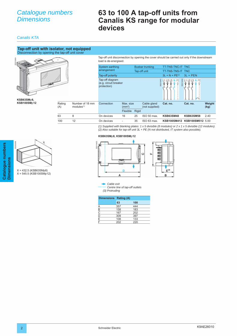
K9AE26010
DD
2104
54
DD
2104
55
DD
2020
08
2 Schneider Electric
Cat
alo
gu
e n
um
ber
sD
imen
sio
ns
Catalogue numbersDimensions
63 to 100 A tap-off units from Canalis KS range for modular devices
System earthing arrangement
Busbar trunking TT-TNS-TNC-IT TNC
Tap-off unit TT-TNS-TNS-IT TNC
Tap-off polarity 3L + N + PE(2) 3L + PEN
Tap-off diagram(e.g. circuit breaker protection) D
D21
0451
DD
2104
52
Rating(A)
Number of 18 mm modules(1)
Connection Max. size (mm2)
Cable gland(not supplied)
Cat. no. Cat. no. Weight (kg)
Flexible Rigid
63 8 On devices 16 25 ISO 50 max. KSB63SM48 KSB63SM58 2.40
100 12 On devices - 35 ISO 63 max. KSB100SM412 KSB100SM512 5.00
Tap-off unit with isolator, not equippedDisconnection by opening the tap-off unit cover
Tap-off unit disconnection by opening the cover should be carried out only if the downstream load is de-energised.
Dimensions Rating (A)
63 100A 357 444B 158 183C 167 202D 309 397E 108 133F 202 220
(1) Supplied with blanking plates: 1 x 5 divisible (8 modules) or 2 x 1 x 5 divisible (12 modules).(2) Also suitable for tap-off unit 3L + PE (N not distributed, IT system also possible).
KSB63SMp8, KSB100SMp12
Canalis KTA
KSB63SMp8,KSB100SMp12
Cable exitCentre line of tap-off outlets
(3) Protruding
X = 432.5 (KSB63SMp8)X = 545.5 (KSB100SMp12)
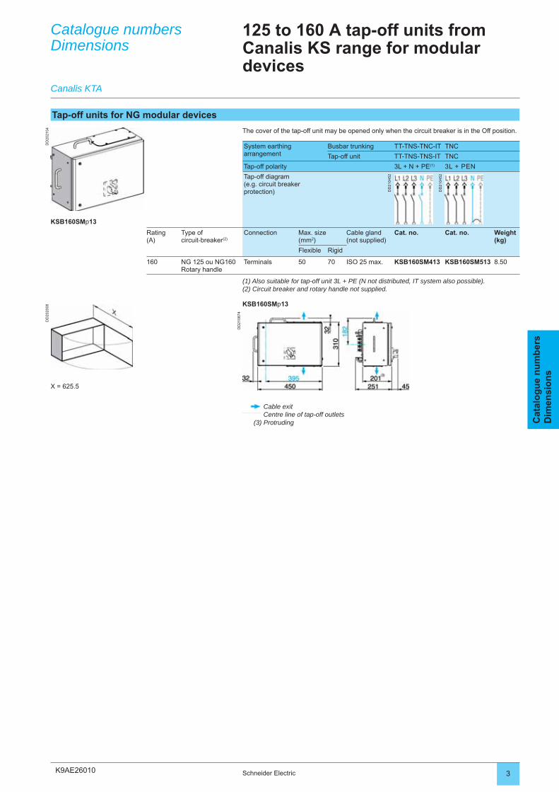
K9AE26010
DD
2021
54D
D20
2008
DD
2108
74
3Schneider Electric
Cat
alo
gu
e n
um
ber
sD
imen
sio
ns
Catalogue numbersDimensions
125 to 160 A tap-off units from Canalis KS range for modular devices
System earthing arrangement
Busbar trunking TT-TNS-TNC-IT TNC
Tap-off unit TT-TNS-TNS-IT TNC
Tap-off polarity 3L + N + PE(1) 3L + PEN
Tap-off diagram(e.g. circuit breaker protection) D
D21
0452
DD
2104
52
Rating(A)
Type ofcircuit-breaker(2)
Connection Max. size(mm2)
Cable gland(not supplied)
Cat. no. Cat. no. Weight (kg)
Flexible Rigid
160 NG 125 ou NG160Rotary handle
Terminals 50 70 ISO 25 max. KSB160SM413 KSB160SM513 8.50
Tap-off units for NG modular devices
The cover of the tap-off unit may be opened only when the circuit breaker is in the Off position.
Canalis KTA
(1) Also suitable for tap-off unit 3L + PE (N not distributed, IT system also possible).(2) Circuit breaker and rotary handle not supplied.
KSB160SMp13
KSB160SMp13
Cable exitCentre line of tap-off outlets
(3) Protruding
X = 625.5
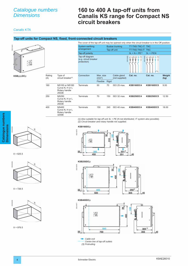
K9AE26010
DD
2104
61
DD
2108
75
DD
2020
08
DD
2108
76
DD
2020
08
DD
2108
77
DD
2020
08
4 Schneider Electric
Cat
alo
gu
e n
um
ber
sD
imen
sio
ns
Catalogue numbersDimensions
Canalis KTA
160 to 400 A tap-off units from Canalis KS range for Compact NS circuit breakers
Tap-off units for Compact NS, fi xed, front-connected circuit breakersThe cover of the tap-off unit may be opened only when the circuit breaker is in the Off position.
System earthing arrangement
Busbar trunking TT-TNS-TNC-IT TNC
Tap-off unit TT-TNS-TNS-IT TNC
Tap-off polarity 3L + N + PE(1) 3L + PEN
Tap-off diagram(e.g. circuit breaker protection) D
D21
0452
DD
2104
52
Rating(A)
Type ofcircuit breaker(2)
Connection Max. size (mm2)
Cable gland(not supplied)
Cat. no. Cat. no. Weight (kg)
Flexible Rigid
160 NS100 or NS160Curve N, H or LRotary handle 29338
Terminals 50 70 ISO 25 max. KSB160DC4 KSB160DC5 9.00
250 NS250Curve N, H or LRotary handle29338
Terminals 70 150 ISO 32 max. KSB250DC4 KSB250DC5 12.50
400 NS400Curve N, H or LRotary handle32598
Terminals 150 240 ISO 40 max. KSB400DC4 KSB400DC5 18.00
(1) Also suitable for tap-off unit 3L + PE (N not distributed, IT system also possible).(2) Circuit breaker and rotary handle not supplied.
KSB160DCp
X = 625.5
KSB250DCp
X = 726.5
KSB400DCp
X = 976.5
Cable exitCentre line of tap-off outlets
(3) Protruding
KSBpppDCp
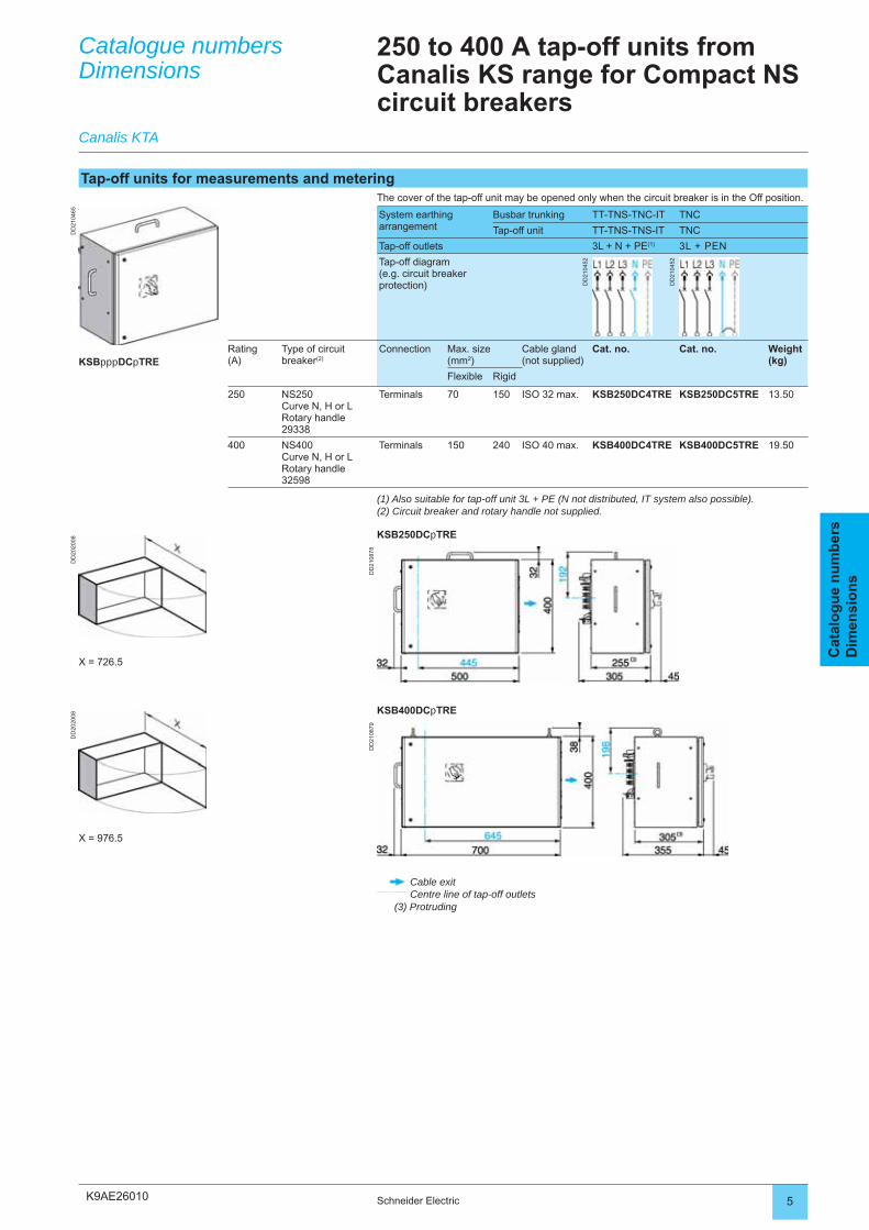
K9AE26010
DD
2104
65
DD
2108
78
DD
2020
08
DD
2108
79
DD
2020
08
5Schneider Electric
Cat
alo
gu
e n
um
ber
sD
imen
sio
ns
Catalogue numbersDimensions
Canalis KTA
250 to 400 A tap-off units from Canalis KS range for Compact NS circuit breakers
Tap-off units for measurements and meteringThe cover of the tap-off unit may be opened only when the circuit breaker is in the Off position.
System earthingarrangement
Busbar trunking TT-TNS-TNC-IT TNC
Tap-off unit TT-TNS-TNS-IT TNC
Tap-off outlets 3L + N + PE(1) 3L + PEN
Tap-off diagram(e.g. circuit breaker protection) D
D21
0452
DD
2104
52
Rating(A)
Type of circuit breaker(2)
Connection Max. size (mm2)
Cable gland(not supplied)
Cat. no. Cat. no. Weight (kg)
Flexible Rigid
250 NS250Curve N, H or LRotary handle29338
Terminals 70 150 ISO 32 max. KSB250DC4TRE KSB250DC5TRE 13.50
400 NS400Curve N, H or LRotary handle32598
Terminals 150 240 ISO 40 max. KSB400DC4TRE KSB400DC5TRE 19.50
(1) Also suitable for tap-off unit 3L + PE (N not distributed, IT system also possible).(2) Circuit breaker and rotary handle not supplied.
KSB250DCpTRE
X = 726.5
KSBpppDCpTRE
KSB400DCpTRE
X = 976.5
Cable exitCentre line of tap-off outlets
(3) Protruding
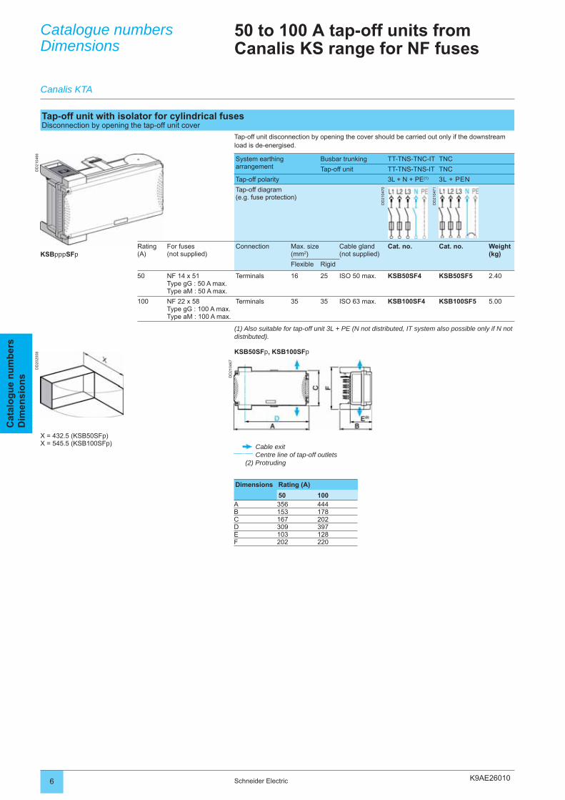
K9AE26010
DD
2104
66
DD
2104
67
DD
2020
08
6 Schneider Electric
Cat
alo
gu
e n
um
ber
sD
imen
sio
ns
Catalogue numbersDimensions
Canalis KTA
50 to 100 A tap-off units from Canalis KS range for NF fuses
Tap-off unit with isolator for cylindrical fusesDisconnection by opening the tap-off unit cover
Tap-off unit disconnection by opening the cover should be carried out only if the downstream load is de-energised.
System earthing arrangement
Busbar trunking TT-TNS-TNC-IT TNC
Tap-off unit TT-TNS-TNS-IT TNC
Tap-off polarity 3L + N + PE(1) 3L + PEN
Tap-off diagram(e.g. fuse protection)
DD
2104
70
DD
2104
71
Rating(A)
For fuses(not supplied)
Connection Max. size (mm2)
Cable gland(not supplied)
Cat. no. Cat. no. Weight (kg)
Flexible Rigid
50 NF 14 x 51Type gG : 50 A max.Type aM : 50 A max.
Terminals 16 25 ISO 50 max. KSB50SF4 KSB50SF5 2.40
100 NF 22 x 58Type gG : 100 A max.Type aM : 100 A max.
Terminals 35 35 ISO 63 max. KSB100SF4 KSB100SF5 5.00
(1) Also suitable for tap-off unit 3L + PE (N not distributed, IT system also possible only if N not distributed).
KSB50SFp, KSB100SFp
KSBpppSFp
X = 432.5 (KSB50SFp)X = 545.5 (KSB100SFp) Cable exit
Centre line of tap-off outlets(2) Protruding
Dimensions Rating (A)
50 100A 356 444B 153 178C 167 202D 309 397E 103 128F 202 220
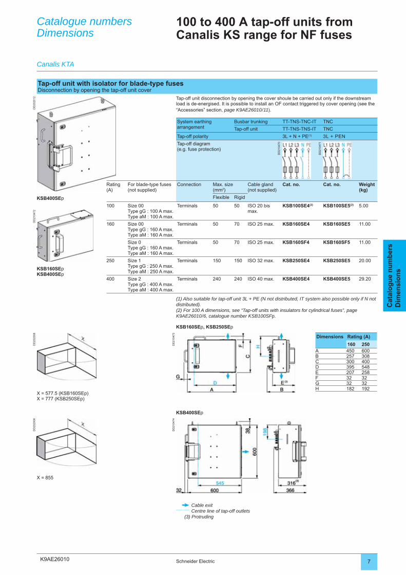
K9AE26010
DD
2020
12D
D21
0472
DD
2104
73
DD
2020
08
DD
2104
74
DD
2020
08
7Schneider Electric
Cat
alo
gu
e n
um
ber
sD
imen
sio
ns
Catalogue numbersDimensions
Canalis KTA
100 to 400 A tap-off units from Canalis KS range for NF fuses
Tap-off unit with isolator for blade-type fusesDisconnection by opening the tap-off unit cover
Tap-off unit disconnection by opening the cover shoule be carried out only if the downstream load is de-energised. It is possible to install an OF contact triggered by cover opening (see the “Accessories” section, page K9AE26010 / 11).
System earthing arrangement
Busbar trunking TT-TNS-TNC-IT TNC
Tap-off unit TT-TNS-TNS-IT TNC
Tap-off polarity 3L + N + PE(1) 3L + PEN
Tap-off diagram(e.g. fuse protection)
DD
2104
70
DD
2104
71
Rating(A)
For blade-type fuses (not supplied)
Connection Max. size (mm2)
Cable gland(not supplied)
Cat. no. Cat. no. Weight (kg)
Flexible Rigid
100 Size 00Type gG : 100 A max.Type aM : 100 A max.
Terminals 50 50 ISO 20 bis max.
KSB100SE4(2) KSB100SE5(2) 5.00
160 Size 00Type gG : 160 A max.Type aM : 160 A max.
Terminals 50 70 ISO 25 max. KSB160SE4 KSB160SE5 11.00
Size 0Type gG : 160 A max.Type aM : 160 A max.
Terminals 50 70 ISO 25 max. KSB160SF4 KSB160SF5 11.00
250 Size 1Type gG : 250 A max.Type aM : 250 A max.
Terminals 150 150 ISO 32 max. KSB250SE4 KSB250SE5 20.00
400 Size 2Type gG : 400 A max.Type aM : 400 A max.
Terminals 240 240 ISO 40 max. KSB400SE4 KSB400SE5 29.20
(1) Also suitable for tap-off unit 3L + PE (N not distributed, IT system also possible only if N not distributed).(2) For 100 A dimensions, see “Tap-off units with insulators for cylindrical fuses”, page K9AE26010 / 6, catalogue number KSB100SFp.
KSB160SEp, KSB250SEp
KSB400SEp
KSB160SEpKSB400SEp
Dimensions Rating (A)
160 250A 450 600B 257 308C 300 400D 395 548E 207 258F 32 32G 32 32H 182 192
X = 577.5 (KSB160SEp)X = 777 (KSB250SEp)
KSB400SEp
X = 855
Cable exitCentre line of tap-off outlets
(3) Protruding
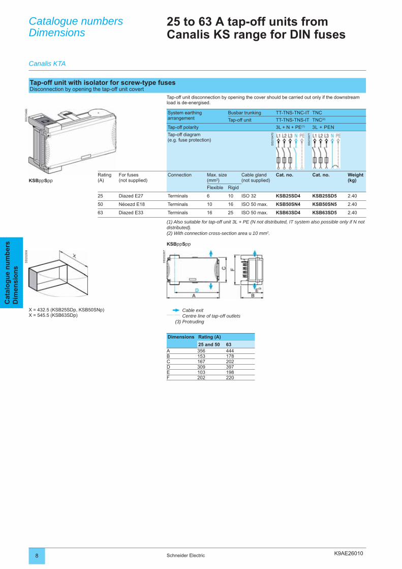
K9AE26010
DD
2104
66
DD
2022
67
DD
2020
08
8 Schneider Electric
Cat
alo
gu
e n
um
ber
sD
imen
sio
ns
Catalogue numbersDimensions
Canalis KTA
25 to 63 A tap-off units from Canalis KS range for DIN fuses
Tap-off unit with isolator for screw-type fusesDisconnection by opening the tap-off unit covert
Tap-off unit disconnection by opening the cover should be carried out only if the downstream load is de-energised.
System earthingarrangement
Busbar trunking TT-TNS-TNC-IT TNC
Tap-off unit TT-TNS-TNS-IT TNC(2)
Tap-off polarity 3L + N + PE(1) 3L + PEN
Tap-off diagram(e.g. fuse protection)
DD
2104
70
DD
2104
71
Rating(A)
For fuses(not supplied)
Connection Max. size (mm2)
Cable gland(not supplied)
Cat. no. Cat. no. Weight (kg)
Flexible Rigid
25 Diazed E27 Terminals 6 10 ISO 32 KSB25SD4 KSB25SD5 2.40
50 Néoezd E18 Terminals 10 16 ISO 50 max. KSB50SN4 KSB50SN5 2.40
63 Diazed E33 Terminals 16 25 ISO 50 max. KSB63SD4 KSB63SD5 2.40
(1) Also suitable for tap-off unit 3L + PE (N not distributed, IT system also possible only if N not distributed).(2) With connection cross-section area u 10 mm2.
KSBppSpp
KSBppSpp
X = 432.5 (KSB25SDp, KSB50SNp)X = 545.5 (KSB63SDp)
Cable exitCentre line of tap-off outlets
(3) Protruding
Dimensions Rating (A)
25 and 50 63A 356 444B 153 178C 167 202D 309 397E 103 198F 202 220
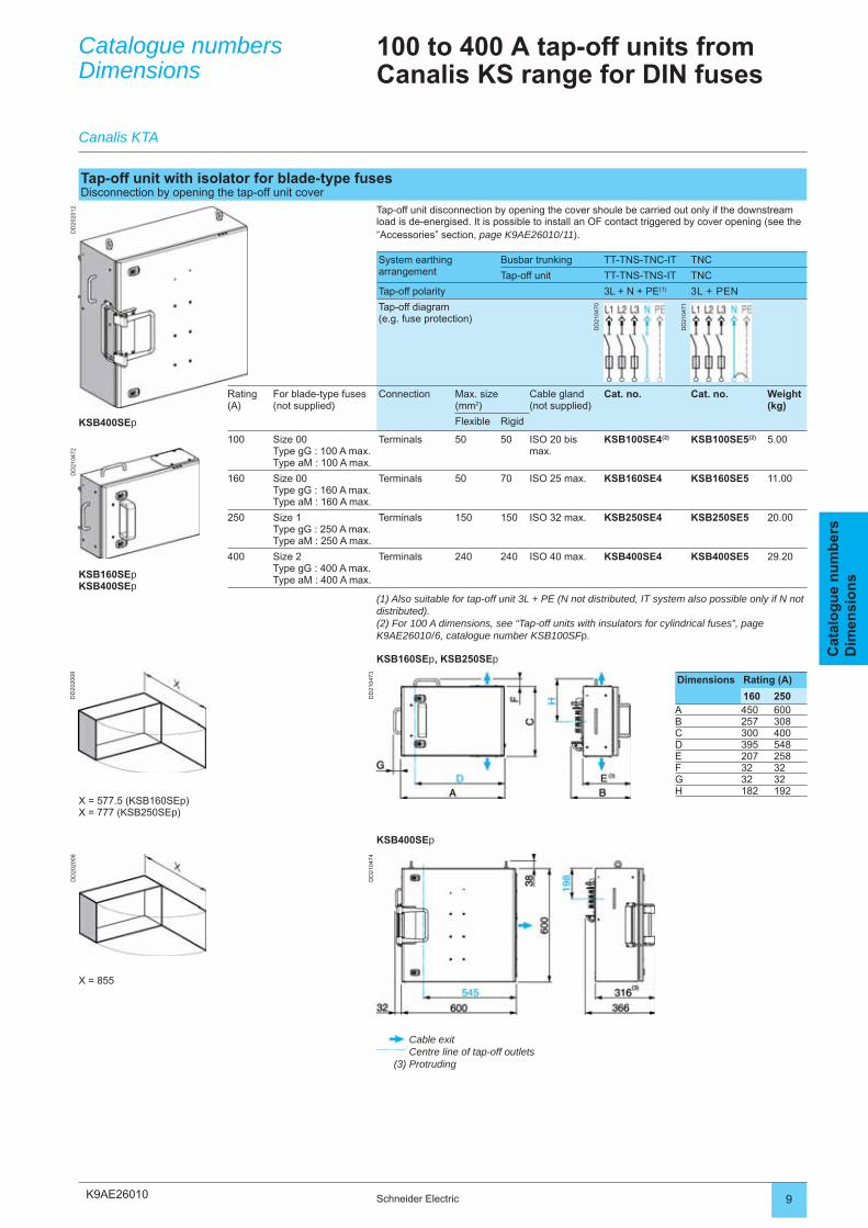
K9AE26010
DD
2020
12D
D21
0472
DD
2104
73D
D21
0474
DD
2020
08D
D20
2008
9Schneider Electric
Cat
alo
gu
e n
um
ber
sD
imen
sio
ns
Catalogue numbersDimensions
Canalis KTA
100 to 400 A tap-off units from Canalis KS range for DIN fuses
Tap-off unit with isolator for blade-type fusesDisconnection by opening the tap-off unit cover
Tap-off unit disconnection by opening the cover shoule be carried out only if the downstream load is de-energised. It is possible to install an OF contact triggered by cover opening (see the “Accessories” section, page K9AE26010 / 11).
System earthing arrangement
Busbar trunking TT-TNS-TNC-IT TNC
Tap-off unit TT-TNS-TNS-IT TNC
Tap-off polarity 3L + N + PE(1) 3L + PEN
Tap-off diagram(e.g. fuse protection)
DD
2104
70
DD
2104
71
Rating(A)
For blade-type fuses (not supplied)
Connection Max. size (mm2)
Cable gland(not supplied)
Cat. no. Cat. no. Weight (kg)
Flexible Rigid
100 Size 00Type gG : 100 A max.Type aM : 100 A max.
Terminals 50 50 ISO 20 bis max.
KSB100SE4(2) KSB100SE5(2) 5.00
160 Size 00Type gG : 160 A max.Type aM : 160 A max.
Terminals 50 70 ISO 25 max. KSB160SE4 KSB160SE5 11.00
250 Size 1Type gG : 250 A max.Type aM : 250 A max.
Terminals 150 150 ISO 32 max. KSB250SE4 KSB250SE5 20.00
400 Size 2Type gG : 400 A max.Type aM : 400 A max.
Terminals 240 240 ISO 40 max. KSB400SE4 KSB400SE5 29.20
(1) Also suitable for tap-off unit 3L + PE (N not distributed, IT system also possible only if N not distributed).(2) For 100 A dimensions, see “Tap-off units with insulators for cylindrical fuses”, page K9AE26010 / 6, catalogue number KSB100SFp.
KSB160SEp, KSB250SEp
KSB400SEp
KSB160SEpKSB400SEp
Dimensions Rating (A)
160 250A 450 600B 257 308C 300 400D 395 548E 207 258F 32 32G 32 32H 182 192
X = 577.5 (KSB160SEp)X = 777 (KSB250SEp)
KSB400SEp
X = 855
Cable exitCentre line of tap-off outlets
(3) Protruding
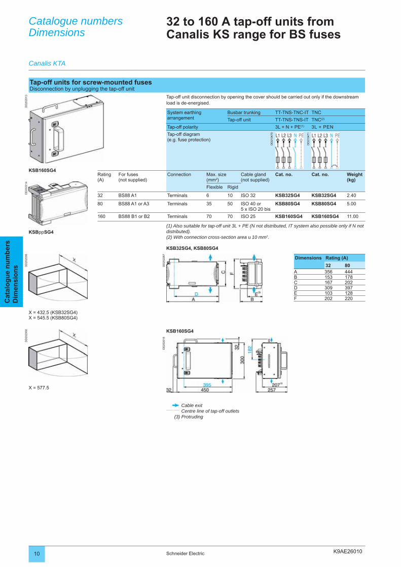
K9AE26010
DD
2020
13D
D20
2014
DD
2022
67
DD
2020
08
DD
2020
15
DD
2020
08
10 Schneider Electric
Cat
alo
gu
e n
um
ber
sD
imen
sio
ns
Catalogue numbersDimensions
Canalis KTA
32 to 160 A tap-off units from Canalis KS range for BS fuses
Tap-off units for screw-mounted fusesDisconnection by unplugging the tap-off unit
Tap-off unit disconnection by opening the cover should be carried out only if the downstream load is de-energised.
System earthing arrangement
Busbar trunking TT-TNS-TNC-IT TNC
Tap-off unit TT-TNS-TNS-IT TNC(2)
Tap-off polarity 3L + N + PE(1) 3L + PEN
Tap-off diagram(e.g. fuse protection)
DD
2104
70
DD
2104
71
Rating(A)
For fuses(not supplied)
Connection Max. size (mm2)
Cable gland(not supplied)
Cat. no. Cat. no. Weight (kg)
Flexible Rigid
32 BS88 A1 Terminals 6 10 ISO 32 KSB32SG4 KSB32SG4 2.40
80 BS88 A1 or A3 Terminals 35 50 ISO 40 or 5 x ISO 20 bis
KSB80SG4 KSB80SG4 5.00
160 BS88 B1 or B2 Terminals 70 70 ISO 25 KSB160SG4 KSB160SG4 11.00
(1) Also suitable for tap-off unit 3L + PE (N not distributed, IT system also possible only if N not distributed).(2) With connection cross-section area u 10 mm2.
KSB32SG4, KSB80SG4
KSB160SG4
KSBppSG4
X = 432.5 (KSB32SG4)X = 545.5 (KSB80SG4)
Dimensions Rating (A)
32 80A 356 444B 153 178C 167 202D 309 397E 103 128F 202 220
KSB160SG4
X = 577.5
Cable exitCentre line of tap-off outlets
(3) Protruding
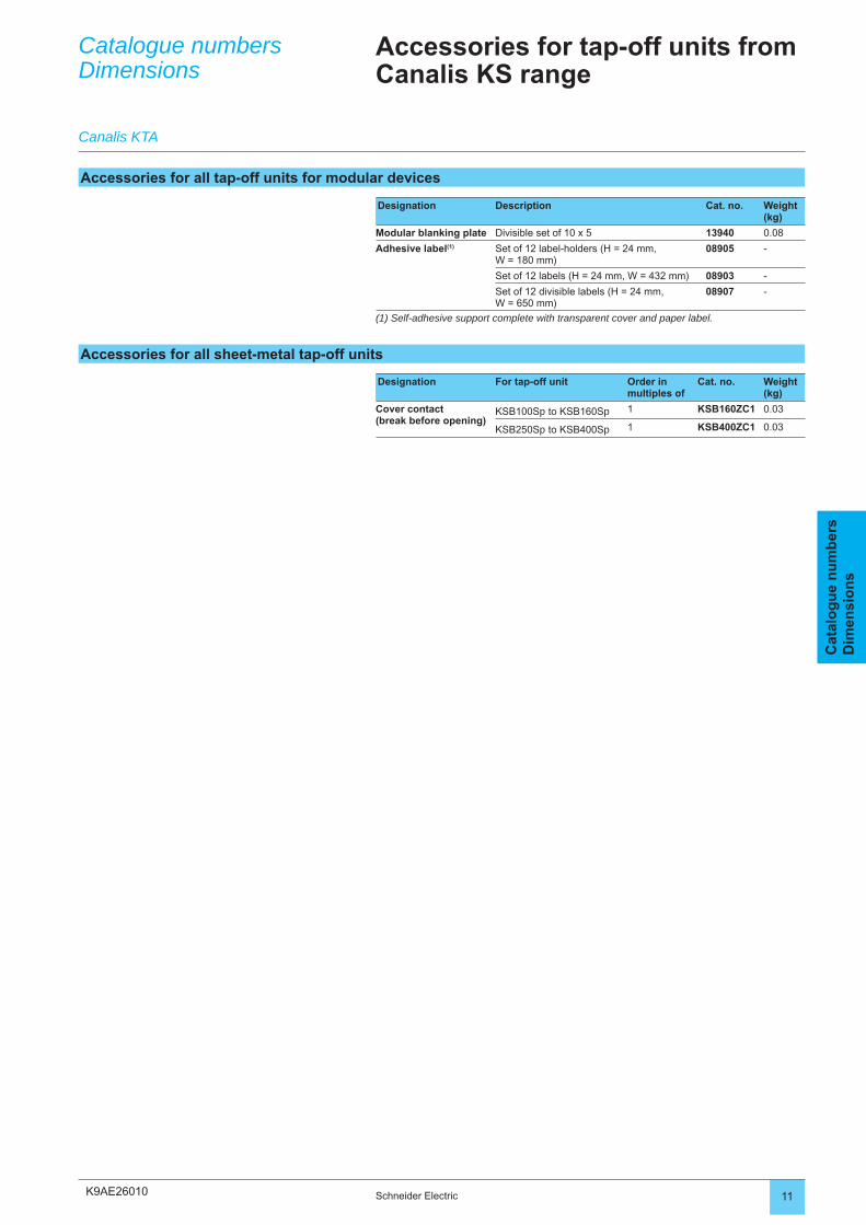
K9AE26010 11Schneider Electric
Cat
alo
gu
e n
um
ber
sD
imen
sio
ns
Catalogue numbersDimensions
Canalis KTA
Accessories for tap-off units from Canalis KS range
Accessories for all tap-off units for modular devices
Designation Description Cat. no. Weight (kg)
Modular blanking plate Divisible set of 10 x 5 13940 0.08
Adhesive label(1) Set of 12 label-holders (H = 24 mm, W = 180 mm)
08905 -
Set of 12 labels (H = 24 mm, W = 432 mm) 08903 -
Set of 12 divisible labels (H = 24 mm, W = 650 mm)
08907 -
(1) Self-adhesive support complete with transparent cover and paper label.
Accessories for all sheet-metal tap-off units
Designation For tap-off unit Order in multiples of
Cat. no. Weight (kg)
Cover contact(break before opening)
KSB100Sp to KSB160Sp 1 KSB160ZC1 0.03
KSB250Sp to KSB400Sp 1 KSB400ZC1 0.03
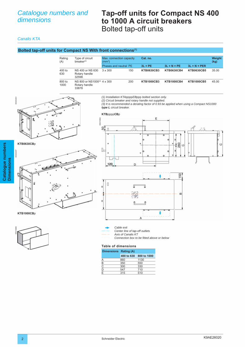
K9AE26020
DD
2024
51
DD
2104
62
DD
2024
97D
D21
0880
2 Schneider Electric
Cat
alo
gu
e n
um
ber
sD
imen
sio
ns
Catalogue numbers and dimensions
Tap-off units for Compact NS 400 to 1000 A circuit breakersBolted tap-off units
Rating(A)
Type of circuit breaker(2)
Max. connection capacity (mm2)
Cat. no. Weight (kg)
Phases and neutral PE 3L + PE 3L + N + PE 3L + N + PER
400 to630
NS 400 or NS 630Rotary handle 32598
3 x 300 150 KTB0630CB3 KTB0630CB4 KTB0630CB5 35.00
800 to 1000
NS 800 or NS1000(3)
Rotary handle33878
4 x 300 200 KTB1000CB3 KTB1000CB4 KTB1000CB5 45.00
Bolted tap-off units for Compact NS With front connections(1)
Canalis KTA
KTB0630CBp
Cable exitCenter line of tap-off outletsAxis of Canalis KTConnection box to be fi tted above or below
(1) Installation KTAppppEBppp bolted section only.(2) Circuit breaker and rotary handle not supplied.(3) It is recommended a derating factor of 0.93 be applied when using a Compact NS1000type L circuit breaker.
KTBppppCBp
Table of dimensions
Dimensions Rating (A)
400 to 630 800 to 1000A 860 1130B 350 550C 300 330D 547 710E 315 510
KTB1000CBp
K9AE26020 3Schneider Electric
Cat
alo
gu
e n
um
ber
sD
imen
sio
ns
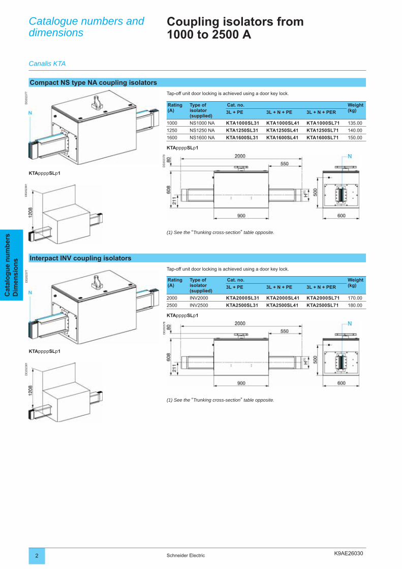
K9AE26030
DD
2023
77
DD
2023
78
DD
2023
81D
D20
2381
DD
2023
77
DD
2023
78
2 Schneider Electric
Réf
éren
ces
En
com
bre
men
tsC
atal
og
ue
nu
mb
ers
Dim
ensi
on
sCatalogue numbers and dimensions
Coupling isolators from1000 to 2500 A
Tap-off unit door locking is achieved using a door key lock.
Rating (A)
Type of isolator (supplied)
Cat. no. Weight (kg)3L + PE 3L + N + PE 3L + N + PER
1000 NS1000 NA KTA1000SL31 KTA1000SL41 KTA1000SL71 135.00
1250 NS1250 NA KTA1250SL31 KTA1250SL41 KTA1250SL71 140.00
1600 NS1600 NA KTA1600SL31 KTA1600SL41 KTA1600SL71 150.00
KTAppppSLp1
Compact NS type NA coupling isolators
Canalis KTA
KTAppppSLp1
(1) See the “Trunking cross-section” table opposite.
Interpact INV coupling isolators
Tap-off unit door locking is achieved using a door key lock.
Rating (A)
Type of isolator (supplied)
Cat. no. Weight (kg)3L + PE 3L + N + PE 3L + N + PER
2000 INV2000 KTA2000SL31 KTA2000SL41 KTA2000SL71 170.00
2500 INV2500 KTA2500SL31 KTA2500SL41 KTA2500SL71 180.00
KTAppppSLp1
KTAppppSLp1
(1) See the “Trunking cross-section” table opposite.
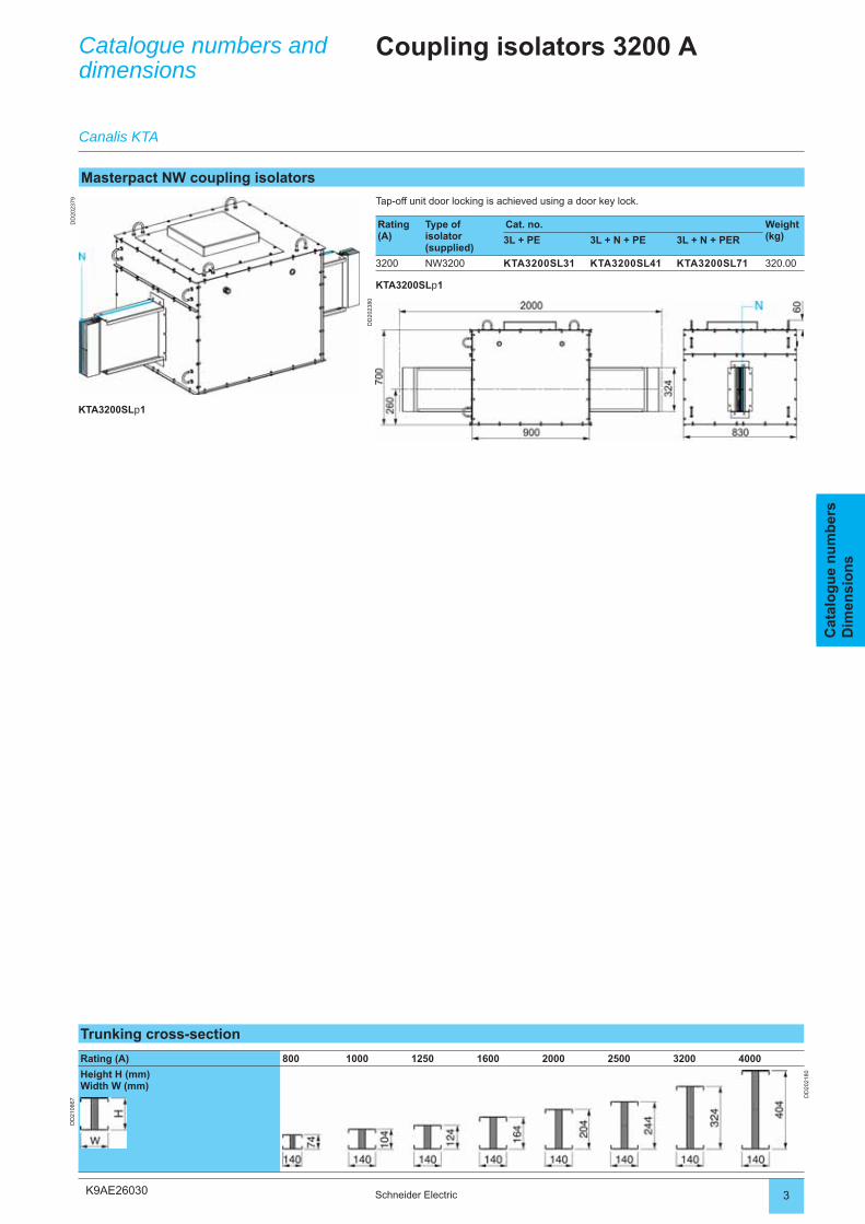
K9AE26030
DD
2023
79
DD
2023
80
3Schneider Electric
Réf
éren
ces
En
com
bre
men
tsC
atal
og
ue
nu
mb
ers
Dim
ensi
on
s
Catalogue numbers and dimensions
Coupling isolators 3200 A
Tap-off unit door locking is achieved using a door key lock.
Rating (A)
Type of isolator (supplied)
Cat. no. Weight (kg)3L + PE 3L + N + PE 3L + N + PER
3200 NW3200 KTA3200SL31 KTA3200SL41 KTA3200SL71 320.00
KTA3200SLp1
Masterpact NW coupling isolators
Canalis KTA
KTA3200SLp1
Trunking cross-section
Rating (A) 800 1000 1250 1600 2000 2500 3200 4000
Height H (mm)Width W (mm)
DD
2021
80
DD
2108
67
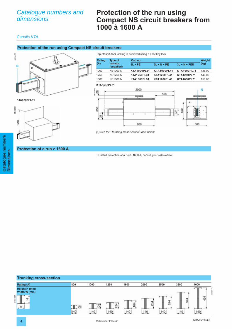
K9AE26030
DD
2023
77
DD
2023
78
DD
2023
81
4 Schneider Electric
Réf
éren
ces
En
com
bre
men
tsC
atal
og
ue
nu
mb
ers
Dim
ensi
on
sCatalogue numbers and dimensions
Protection of the run using Compact NS circuit breakers from1000 à 1600 A
Tap-off unit door locking is achieved using a door key lock.
Rating (A)
Type of isolator (supplied)
Cat. no. Weight (kg)3L + PE 3L + N + PE 3L + N + PER
1000 NS1000 N KTA1000PL31 KTA1000PL41 KTA1000PL71 135.00
1250 NS1250 N KTA1250PL31 KTA1250PL41 KTA1250PL71 140.00
1600 NS1600 N KTA1600PL31 KTA1600PL41 KTA1600PL71 150.00
KTAppppPLp1
Protection of the run using Compact NS circuit breakers
Canalis KTA
KTAppppPLp1
Protection of a run > 1600 A
(1) See the “Trunking cross-section” table below.
To install protection of a run > 1600 A, consult your sales offi ce.
Trunking cross-section
Rating (A) 800 1000 1250 1600 2000 2500 3200 4000
Height H (mm)Width W (mm)
DD
2021
80
DD
2108
67

K9AE26030 5Schneider Electric
Réf
éren
ces
En
com
bre
men
tsC
atal
og
ue
nu
mb
ers
Dim
ensi
on
s
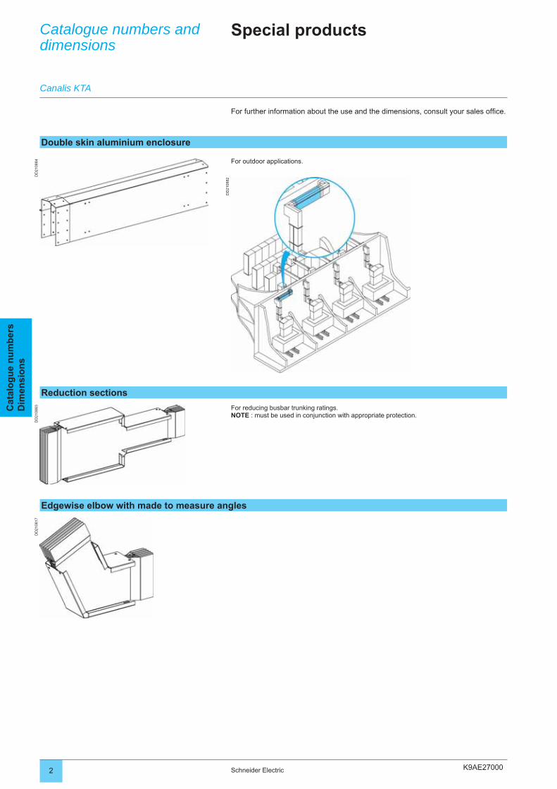
K9AE27000
DD
2108
84
DD
2108
82
DD
2108
17D
D21
0883
2 Schneider Electric
Cat
alo
gu
e n
um
ber
sD
imen
sio
ns
Catalogue numbers and dimensions
Special products
For outdoor applications.
Double skin aluminium enclosure
Canalis KTA
Reduction sections
For reducing busbar trunking ratings.NOTE : must be used in conjunction with appropriate protection.
For further information about the use and the dimensions, consult your sales offi ce.
Edgewise elbow with made to measure angles
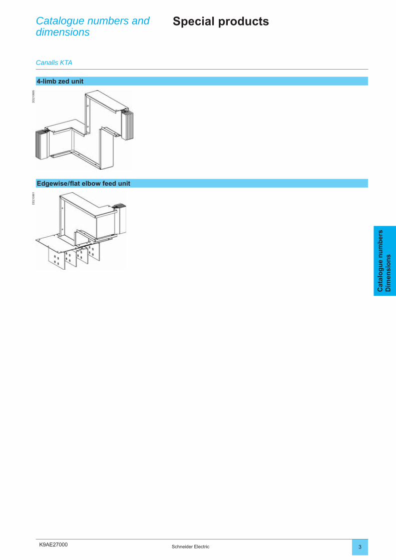
K9AE27000
DD
2108
85D
D21
0881
3Schneider Electric
Cat
alo
gu
e n
um
ber
sD
imen
sio
ns
4-limb zed unit
Edgewise / fl at elbow feed unit
Catalogue numbers and dimensions
Canalis KTA
Special products
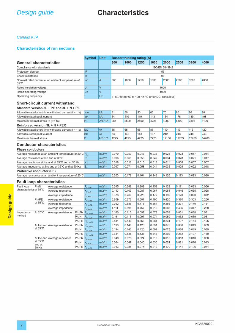
K9AE390002 Schneider Electric
Des
ign
gu
ide
Design guide Characteristics
Characteristics of run sections
Symbol Unit Busbar trunking rating (A)
General characteristics 800 1000 1250 1600 2000 2500 3200 4000
Compliance with standards IEC / EN 60439-2
Protection degree IP 55
Shock resistance IK 08
Nominal rated current at an ambient temperature of 35°C
Inc A 800 1000 1250 1600 2000 2500 3200 4000
Rated insulation voltage Ui V 1000
Rated operating voltage Ue V 1000
Operating frequency f Hz c 50 / 60 (for 60 to 400 Hz AC or for DC, consult us)
Short-circuit current withstandStandard version 3L + PE and 3L + N + PEAllowable rated short-time withstand current (t = 1 s) Icw kA 31 50 50 65 70 80 86 90
Allowable rated peak current Ipk kA 64 110 110 143 154 176 189 198
Maximum thermal stress I2t (t = 1s) I2t A2s 106 961 2500 2500 4225 4900 6400 7396 8100
Reinforced version 3L + N + PERAllowable rated short-time withstand current (t = 1 s) Icw kA 35 65 65 85 110 113 113 120
Allowable rated peak current Ipk kA 73 143 143 187 242 248 248 246
Maximum thermal stress I2t A2S.106 1225 4225 4225 7225 12100 12769 12769 14400
Conductor characteristicsPhase conductorsAverage resistance at an ambient temperature of 20°C R
20mΩ / m 0.079 0.057 0.046 0.035 0.028 0.023 0.017 0.014
Average resistance at Inc and at 35°C R1
mΩ / m 0.096 0.069 0.056 0.042 0.034 0.028 0.021 0.017
Average reactance at Inc and at 35°C and at 50 Hz X1
mΩ / m 0.018 0.016 0.015 0.013 0.011 0.008 0.007 0.007
Average impedance at Inc and at 35°C and at 50 Hz Z1
mΩ / m 0.097 0.071 0.058 0.044 0.035 0.029 0.022 0.018
Protective conductor (PE)Average resistance at an ambient temperature of 20°C mΩ / m 0.203 0.178 0.164 0.143 0.126 0.113 0.093 0.080
Fault loop characteristicsFault loop characteristics
Ph / N at 35°C
Average resistance R0 ph / N
mΩ / m 0.345 0.248 0.209 0.159 0.128 0.111 0.083 0.066
Average reactance X0 ph / N
mΩ / m 0.143 0.103 0.087 0.067 0.054 0.046 0.035 0.028
Average impedance Z0 ph / N
mΩ / m 0.373 0.269 0.226 0.172 0.139 0.120 0.090 0.072
Ph / PE at 35°C
Average resistance R0 ph / PE
mΩ / m 0.809 0.676 0.587 0.490 0.420 0.370 0.303 0.256
Average reactance X0 ph / PE
mΩ / m 0.762 0.586 0.478 0.364 0.286 0.231 0.170 0.131
Average impedance Z0 ph / PE
mΩ / m 1.111 0.895 0.757 0.610 0.508 0.436 0.347 0.288
Impedance method
At 20°C Average resistance Ph / Ph Rb0 ph / ph
mΩ / m 0.160 0.115 0.097 0.073 0.059 0.051 0.038 0.031
Ph / N Rb0 ph / N
mΩ / m 0.161 0.115 0.097 0.074 0.059 0.052 0.039 0.031
Ph / PE Rb0 ph / PE
mΩ / m 0.531 0.440 0.353 0.281 0.231 0.197 0.154 0.125
At Inc and at 35°C
Average resistance Ph / Ph Rb0 ph / ph
mΩ / m 0.193 0.140 0.120 0.091 0.075 0.066 0.049 0.039
Ph / N Rb0 ph / N
mΩ / m 0.194 0.140 0.120 0.092 0.075 0.066 0.049 0.039
Ph / PE Rb0 ph / PE
mΩ / m 0.641 0.535 0.438 0.348 0.292 0.252 0.197 0.160
At Inc and at 35°C and at 50 Hz
Average reactance Ph / Ph Xb ph / ph
mΩ / m 0.040 0.029 0.024 0.019 0.015 0.013 0.010 0.008
Ph / N Xb ph / N
mΩ / m 0.064 0.047 0.040 0.030 0.024 0.021 0.016 0.013
Ph / PE Xb ph / PE
mΩ / m 0.043 0.086 0.275 0.212 0.170 0.141 0.106 0.084
Canalis KTA
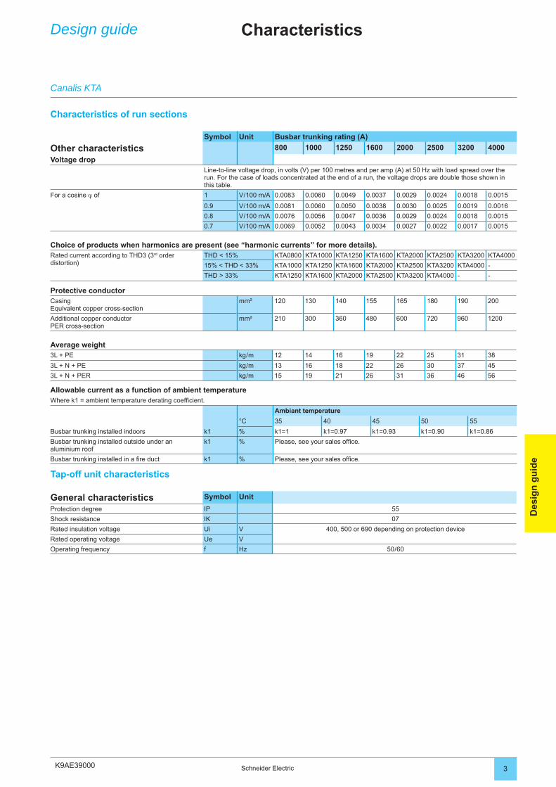
K9AE39000 3Schneider Electric
Des
ign
gu
ide
Characteristics of run sections
Symbol Unit Busbar trunking rating (A)
Other characteristics 800 1000 1250 1600 2000 2500 3200 4000
Voltage dropLine-to-line voltage drop, in volts (V) per 100 metres and per amp (A) at 50 Hz with load spread over the run. For the case of loads concentrated at the end of a run, the voltage drops are double those shown in this table.
For a cosine ϕ of 1 V / 100 m / A 0.0083 0.0060 0.0049 0.0037 0.0029 0.0024 0.0018 0.0015
0.9 V / 100 m / A 0.0081 0.0060 0.0050 0.0038 0.0030 0.0025 0.0019 0.0016
0.8 V / 100 m / A 0.0076 0.0056 0.0047 0.0036 0.0029 0.0024 0.0018 0.0015
0.7 V / 100 m / A 0.0069 0.0052 0.0043 0.0034 0.0027 0.0022 0.0017 0.0015
Choice of products when harmonics are present (see “harmonic currents” for more details).Rated current according to THD3 (3rd order distortion)
THD < 15% KTA0800 KTA1000 KTA1250 KTA1600 KTA2000 KTA2500 KTA3200 KTA4000
15% < THD < 33% KTA1000 KTA1250 KTA1600 KTA2000 KTA2500 KTA3200 KTA4000 -
THD > 33% KTA1250 KTA1600 KTA2000 KTA2500 KTA3200 KTA4000 - -
Protective conductorCasingEquivalent copper cross-section
mm² 120 130 140 155 165 180 190 200
Additional copper conductorPER cross-section
mm² 210 300 360 480 600 720 960 1200
Average weight3L + PE kg / m 12 14 16 19 22 25 31 38
3L + N + PE kg / m 13 16 18 22 26 30 37 45
3L + N + PER kg / m 15 19 21 26 31 36 46 56
Allowable current as a function of ambient temperatureWhere k1 = ambient temperature derating coeffi cient.
Ambiant temperature
°C 35 40 45 50 55
Busbar trunking installed indoors k1 % k1=1 k1=0.97 k1=0.93 k1=0.90 k1=0.86
Busbar trunking installed outside under an aluminium roof
k1 % Please, see your sales offi ce.
Busbar trunking installed in a fi re duct k1 % Please, see your sales offi ce.
Tap-off unit characteristics
General characteristics Symbol Unit
Protection degree IP 55
Shock resistance IK 07
Rated insulation voltage Ui V 400, 500 or 690 depending on protection device
Rated operating voltage Ue V
Operating frequency f Hz 50 / 60
Design guide
Canalis KTA
Characteristics
K9AE31000
DD202142
2 Schneider Eletric
Des
ign
gu
ide
Design guide Determining the ratingProviding power distribution using Canalis
Apart from extreme atmospheres, Canalis can be installed anywhere!The order described below is only aimed at presenting the different stages for a simple installation. For a detailed design, it is necessary to use appropriate tools, approved by control bodies, in compliance with local installation standards.The Ecodial software, edited by Schneider Electric, meets this requirement perfectly.
Design order:1 – Defi ne run layouts.2 – Identify external infl uences.3 – Determine the current rating (Ib).4 – Calculate the nominal current (In) taking into account derating coeffi cients.5 – Choose the busbar trunking rating.6 – Check the rating with respect to allowable voltage drop.7 – Check busbar trunking overloads.8 – Check the rating with respect to short-circuit withstand current.9 – Choose the source and feeder circuit breakers.
Protection degreeCanalis KT busbar trunking is IP55 and IPxxD by construction.This protection degree protects the busbar trunking against:
dust,penetration by a 1mm diameter wire,water projections from all directions.
It can be installed in almost all premises; for more details see the “Determining the protection degree” pages.
Wherever the busbar trunking must pass outside the building, an aluminium roof can be supplied; consult your Schneider Electric distributor for information concerning this option.
Corrosive atmosphereThe busbar trunking has been qualifi ed for industrial atmospheres.For sulphurous atmospheres such as sulphur dioxide (SO2) and hydrogen sulphide (H2S), there is a suitable Canalis KT solution; consult your Schneider Electric distributor for more information on this option.Example: paper mills, water treatment works, etc.
bbb
The layout of the distribution runs depends on the position of the loads and where the source is located.Load protection is placed in the tap-off boxes, at the point of use.
A single and same Canalis busbar trunking supplies a group of loads of different ratings.
Schneider Electric has tools you can use to help you choose the architecture best suited to your application:
the Idpro software to simulate the organisation of your electrical networks, application orientated technical guides (car industry, data centers, shopping
centres, etc).
bb
Canalis KTA
1 - Canalis busbar trunking layout
2 - Identifi cation of external infl uences
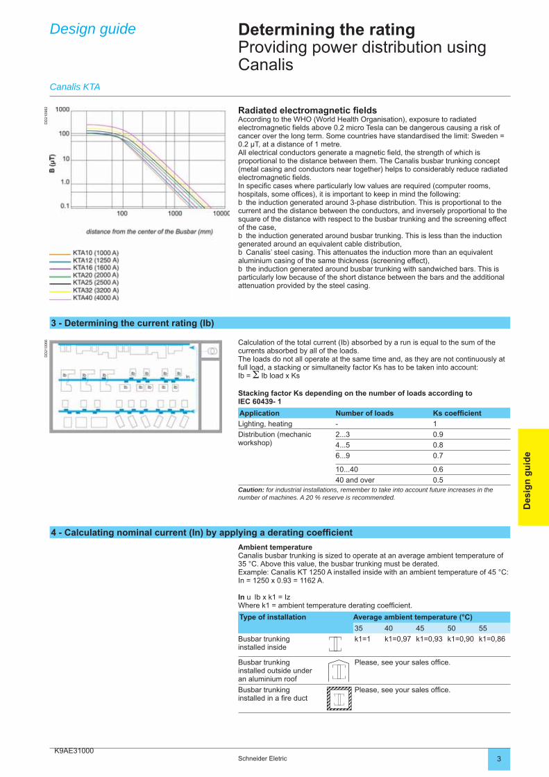
K9AE31000
DD
2100
66
3Schneider Eletric
Des
ign
gu
ide
Design guide Determining the ratingProviding power distribution using Canalis
Calculation of the total current (Ib) absorbed by a run is equal to the sum of the currents absorbed by all of the loads.The loads do not all operate at the same time and, as they are not continuously at full load, a stacking or simultaneity factor Ks has to be taken into account:Ib = Σ Ib load x Ks
Stacking factor Ks depending on the number of loads according to IEC 60439- 1
Application Number of loads Ks coeffi cient
Lighting, heating - 1
Distribution (mechanic workshop)
2...3 0.9
4...5 0.8
6...9 0.7
10...40 0.6
40 and over 0.5Caution: for industrial installations, remember to take into account future increases in the number of machines. A 20 % reserve is recommended.
Radiated electromagnetic fi eldsAccording to the WHO (World Health Organisation), exposure to radiated electromagnetic fi elds above 0.2 micro Tesla can be dangerous causing a risk of cancer over the long term. Some countries have standardised the limit: Sweden = 0.2 µT, at a distance of 1 metre.All electrical conductors generate a magnetic fi eld, the strength of which is proportional to the distance between them. The Canalis busbar trunking concept (metal casing and conductors near together) helps to considerably reduce radiated electromagnetic fi elds.In specifi c cases where particularly low values are required (computer rooms, hospitals, some offi ces), it is important to keep in mind the following:
the induction generated around 3-phase distribution. This is proportional to the current and the distance between the conductors, and inversely proportional to the square of the distance with respect to the busbar trunking and the screening effect of the case,
the induction generated around busbar trunking. This is less than the induction generated around an equivalent cable distribution,
Canalis’ steel casing. This attenuates the induction more than an equivalent aluminium casing of the same thickness (screening effect),
the induction generated around busbar trunking with sandwiched bars. This is particularly low because of the short distance between the bars and the additional attenuation provided by the steel casing.
b
b
b
b
Ambient temperatureCanalis busbar trunking is sized to operate at an average ambient temperature of 35 °C. Above this value, the busbar trunking must be derated.Example: Canalis KT 1250 A installed inside with an ambient temperature of 45 °C: In = 1250 x 0.93 = 1162 A.
In u Ib x k1 = IzWhere k1 = ambient temperature derating coeffi cient.
Type of installation Average ambient temperature (°C)
35 40 45 50 55
Busbar trunkinginstalled inside
k1=1 k1=0,97 k1=0,93 k1=0,90 k1=0,86
Busbar trunkinginstalled outside under an aluminium roof
Please, see your sales offi ce.
Busbar trunkinginstalled in a fi re duct
Please, see your sales offi ce.
Canalis KTA
3 - Determining the current rating (Ib)
4 - Calculating nominal current (ln) by applying a derating coeffi cient
DD
2109
82
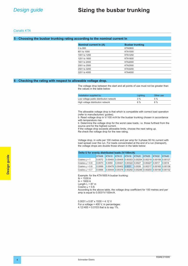
K9AE310004 Schneider Eletric
Des
ign
gu
ide
Sizing the busbar trunking
The voltage drop between the start and all points of use must not be greater than the values in the table below:
Installation supplied by: Lighting Other use
Low voltage public distribution network 3 % 5 %
High voltage distribution network 6 % 8 %
The allowable voltage drop is that which is compatible with correct load operation (refer to manufacturers’ guides).
Read voltage drop in V / 100 m / A for the busbar trunking chosen in accordance with temperature rise.
Determine the voltage drop for the worst case loads, i.e. those furthest from the source and for the highest current. If the voltage drop exceeds allowable limits, choose the next rating up.Re-check the voltage drop for the new rating.
Voltage drop, in volts per 100 metres and per amp for 3-phase 50 Hz current with load spread over the run. For loads concentrated at the end of a run (transport), the voltage drops are double those shown in the table below:
Delta U for evenly distributed loads (V / 100m / A)KTA08 KTA10 KTA12 KTA16 KTA20 KTA25 KTA32 KTA40
Cosine ϕ = 1 0.0072 0.00493 0.00405 0.00303 0.00254 0.00219 0.00158 0.00127
Cosine ϕ = 0.9 0.0073 0.0050 0.00421 0.00322 0.0027 0.00227 0.0017 0.0014
Cosine ϕ = 0.8 0.0069 0.00478 0.00402 0.0031 0.0026 0.00217 0.00165 0.00138
Cosine ϕ = 0.7 0.0064 0.00444 0.00376 0.00292 0.00246 0.00203 0.00156 0.00132
Example: for the KTA1600 A busbar trunking: Ib = 1530 AIn = 1600 ALength L = 87 mCosine ϕ = 0.8.According to the above table, the voltage drop coeffi cient for 100 metres and per amp is equal to 0.0031V / 100m / A.
0.0031 x 0.87 x 1530 = 4.12 VFor a voltage = 400 V, in percentages:4.12 / 400 = 0.0103 that is to say 1%.
b
b
Design guide
Nominal current In (A) Busbar trunking0 to 800 KTA0800
801 to 1000 KTA1000
1001 to 1250 KTA1250
1251 to 1600 KTA1600
1601 to 2000 KTA2000
2001 to 2500 KTA2500
2501 to 3200 KTA3200
3201 to 4000 KTA4000
Canalis KTA
6 - Checking the rating with respect to allowable voltage drop.
5 - Choosing the busbar trunking rating according to the nominal current ln
K9AE310005Schneider Eletric
Des
ign
gu
ide
Short-circuit current withstand is shown in the table below.This value must be greater than the prospective short-circuit current, at all points of the installation.
Calculate the short-circuit current value at the worst case points.Check the chosen rating allows the busbar trunking to cope with this short-circuit
current. If this is not the case, there are 2 possible solutions:choose a higher rating busbar trunking and re-check,provide a peak current limiting protection system upstream of the busbar
trunking.
Standard version 3L + N + PE or 3L + PEUnit KTA08 KTA10 KTA12 KTA16 KTA20 KTA25 KTA30 KTA40
Allowable rated short-time withstand current (t =1s)
Icw kArms / 1s 31 50 50 65 70 80 86 90
Allowable rated peak current
Ipk k 64 110 110 143 154 176 189 198
Maximum thermal stress
I2t A2s.106 961 2500 2500 4225 4900 6400 7396 8100
Reinforced version 3L + N+ PERAllowable rated short-time withstand current (t=1s)
Icw kArms / 1s 35 65 65 85 110 113 113 120
Allowable rated peak current
Ipk k 73 143 143 187 242 248 248 264
Maximum thermal stress
I2t A2s.106 1225 4225 4225 7225 12100 12769 12769 14400
Canalis KT is more than sized to cope with short-circuit currents. Some specifi c cases require checks to be carried out: transformers in parallel, low rating Canalis installed close to a transformer, etc.
bb
bbb
To allow for extensions, the busbar trunking is generally protected at its nominal current Inc (or its allowable current Iz if the ambient temperature coeffi cient k1 is applied).
Circuit breaker protection: adjust Ir of the circuit breaker such that:
Iz = Ib x k1 y Ir y Inc
Circuit breaker protection allows the Canalis busbar trunking to be used at full capacity because the standardised nominal current In of the circuit breaker is In y Inc / K2 where K2 = 1.
Protection using gG (gI) fuse:determine the standardised nominal current In of the fuse such that: In y Inc / K2where K2 = 1.1.choose the standardised rating In that is equal to or just lower.
Check the following condition: In u Ib x k1 = Iz. If this condition is not met, choose the busbar trunking with the next rating up.
Note: using gI fuses for protection means reducing the busbar trunking’s allowable current.
bv
bvvv
Design guide Sizing the busbar trunking
Canalis KTA
8 - Checking the rating and choice of circuit breaker with respect to short-circuit withstand current
7 - Protecting against busbar trunking overloads.
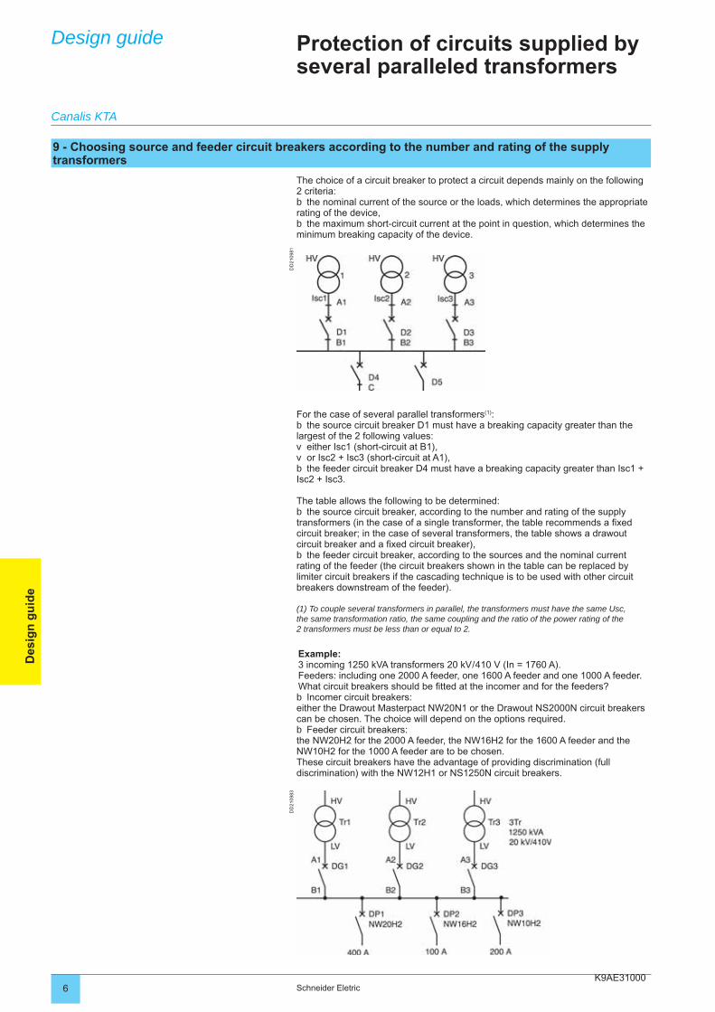
K9AE310006 Schneider Eletric
Des
ign
gu
ide
Design guide Protection of circuits supplied by several paralleled transformers
The choice of a circuit breaker to protect a circuit depends mainly on the following 2 criteria:
the nominal current of the source or the loads, which determines the appropriate rating of the device,
the maximum short-circuit current at the point in question, which determines the minimum breaking capacity of the device.
b
b
For the case of several parallel transformers(1):the source circuit breaker D1 must have a breaking capacity greater than the
largest of the 2 following values:either Isc1 (short-circuit at B1),or Isc2 + Isc3 (short-circuit at A1),the feeder circuit breaker D4 must have a breaking capacity greater than Isc1 +
Isc2 + Isc3.
The table allows the following to be determined:the source circuit breaker, according to the number and rating of the supply
transformers (in the case of a single transformer, the table recommends a fi xed circuit breaker; in the case of several transformers, the table shows a drawout circuit breaker and a fi xed circuit breaker),
the feeder circuit breaker, according to the sources and the nominal current rating of the feeder (the circuit breakers shown in the table can be replaced by limiter circuit breakers if the cascading technique is to be used with other circuit breakers downstream of the feeder).
(1) To couple several transformers in parallel, the transformers must have the same Usc, the same transformation ratio, the same coupling and the ratio of the power rating of the 2 transformers must be less than or equal to 2.
Example:3 incoming 1250 kVA transformers 20 kV / 410 V (In = 1760 A).Feeders: including one 2000 A feeder, one 1600 A feeder and one 1000 A feeder.What circuit breakers should be fi tted at the incomer and for the feeders?
Incomer circuit breakers:either the Drawout Masterpact NW20N1 or the Drawout NS2000N circuit breakers can be chosen. The choice will depend on the options required.
Feeder circuit breakers:the NW20H2 for the 2000 A feeder, the NW16H2 for the 1600 A feeder and the NW10H2 for the 1000 A feeder are to be chosen.These circuit breakers have the advantage of providing discrimination (full discrimination) with the NW12H1 or NS1250N circuit breakers.
b
vvb
b
b
b
b
Canalis KTA
9 - Choosing source and feeder circuit breakers according to the number and rating of the supply transformers
DD
2109
83D
D21
0981
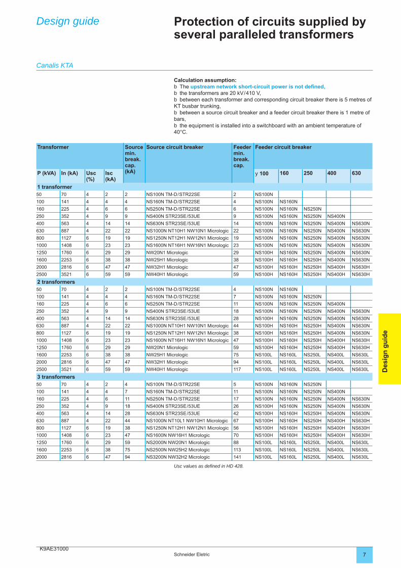
K9AE310007Schneider Eletric
Des
ign
gu
ide
Design guide Protection of circuits supplied by several paralleled transformers
Calculation assumption:The upstream network short-circuit power is not defi ned,the transformers are 20 kV / 410 V,between each transformer and corresponding circuit breaker there is 5 metres of
KT busbar trunking,between a source circuit breaker and a feeder circuit breaker there is 1 metre of
bars,the equipment is installed into a switchboard with an ambient temperature of
40°C.
bbb
b
b
Canalis KTA
Transformer Source min. break. cap. (kA)
Source circuit breaker Feeder min. break. cap.
Feeder circuit breaker
P (kVA) In (kA) Usc (%)
Isc (kA)
y 100 160 250 400 630
1 transformer50 70 4 2 2 NS100N TM-D / STR22SE 2 NS100N
100 141 4 4 4 NS160N TM-D / STR22SE 4 NS100N NS160N
160 225 4 6 6 NS250N TM-D / STR22SE 6 NS100N NS160N NS250N
250 352 4 9 9 NS400N STR23SE / 53UE 9 NS100N NS160N NS250N NS400N
400 563 4 14 14 NS630N STR23SE / 53UE 14 NS100N NS160N NS250N NS400N NS630N
630 887 4 22 22 NS1000N NT10H1 NW10N1 Micrologic 22 NS100N NS160N NS250N NS400N NS630N
800 1127 6 19 19 NS1250N NT12H1 NW12N1 Micrologic 19 NS100N NS160N NS250N NS400N NS630N
1000 1408 6 23 23 NS1600N NT16H1 NW16N1 Micrologic 23 NS100N NS160N NS250N NS400N NS630N
1250 1760 6 29 29 NW20N1 Micrologic 29 NS100H NS160N NS250N NS400N NS630N
1600 2253 6 38 38 NW25H1 Micrologic 38 NS100H NS160H NS250H NS400N NS630N
2000 2816 6 47 47 NW32H1 Micrologic 47 NS100H NS160H NS250H NS400H NS630H
2500 3521 6 59 59 NW40H1 Micrologic 59 NS100H NS160H NS250H NS400H NS630H
2 transformers50 70 4 2 2 NS100N TM-D / STR22SE 4 NS100N NS160N
100 141 4 4 4 NS160N TM-D / STR22SE 7 NS100N NS160N NS250N
160 225 4 6 6 NS250N TM-D / STR22SE 11 NS100N NS160N NS250N NS400N
250 352 4 9 9 NS400N STR23SE / 53UE 18 NS100N NS160N NS250N NS400N NS630N
400 563 4 14 14 NS630N STR23SE / 53UE 28 NS100H NS160N NS250N NS400N NS630N
630 887 4 22 22 NS1000N NT10H1 NW10N1 Micrologic 44 NS100H NS160H NS250H NS400N NS630N
800 1127 6 19 19 NS1250N NT12H1 NW12N1 Micrologic 38 NS100H NS160H NS250H NS400N NS630N
1000 1408 6 23 23 NS1600N NT16H1 NW16N1 Micrologic 47 NS100H NS160H NS250H NS400H NS630H
1250 1760 6 29 29 NW20N1 Micrologic 59 NS100H NS160H NS250H NS400H NS630H
1600 2253 6 38 38 NW25H1 Micrologic 75 NS100L NS160L NS250L NS400L NS630L
2000 2816 6 47 47 NW32H1 Micrologic 94 NS100L NS160L NS250L NS400L NS630L
2500 3521 6 59 59 NW40H1 Micrologic 117 NS100L NS160L NS250L NS400L NS630L
3 transformers 50 70 4 2 4 NS100N TM-D / STR22SE 5 NS100N NS160N NS250N
100 141 4 4 7 NS160N TM-D / STR22SE 11 NS100N NS160N NS250N NS400N
160 225 4 6 11 NS250N TM-D / STR22SE 17 NS100N NS160N NS250N NS400N NS630N
250 352 4 9 18 NS400N STR23SE / 53UE 26 NS100H NS160N NS250N NS400N NS630N
400 563 4 14 28 NS630N STR23SE / 53UE 42 NS100H NS160H NS250H NS400N NS630N
630 887 4 22 44 NS1000N NT10L1 NW10H1 Micrologic 67 NS100H NS160H NS250H NS400H NS630H
800 1127 6 19 38 NS1250N NT12H1 NW12N1 Micrologic 56 NS100H NS160H NS250H NS400H NS630H
1000 1408 6 23 47 NS1600N NW16H1 Micrologic 70 NS100H NS160H NS250H NS400H NS630H
1250 1760 6 29 59 NS2000N NW20N1 Micrologic 88 NS100L NS160L NS250L NS400L NS630L
1600 2253 6 38 75 NS2500N NW25H2 Micrologic 113 NS100L NS160L NS250L NS400L NS630L
2000 2816 6 47 94 NS3200N NW32H2 Micrologic 141 NS100L NS160L NS250L NS400L NS630L
Usc values as defi ned in HD 428.
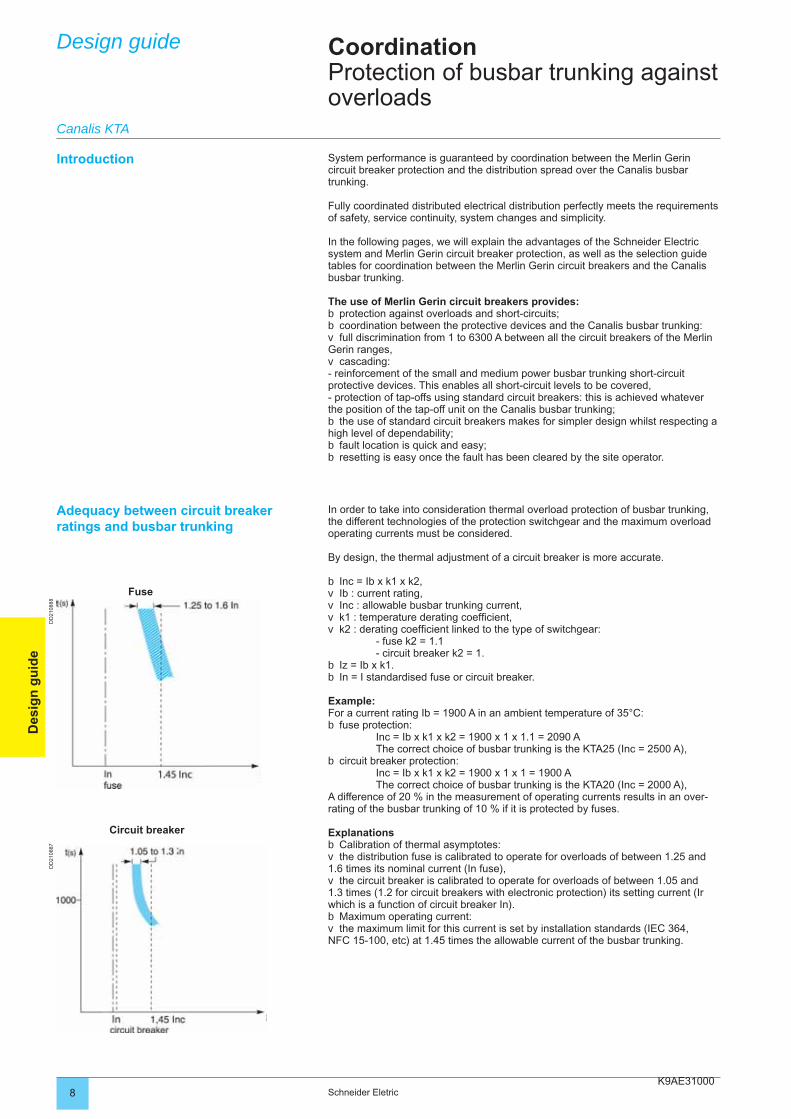
K9AE310008 Schneider Eletric
Des
ign
gu
ide
Design guide
System performance is guaranteed by coordination between the Merlin Gerin circuit breaker protection and the distribution spread over the Canalis busbar trunking.
Fully coordinated distributed electrical distribution perfectly meets the requirements of safety, service continuity, system changes and simplicity.
In the following pages, we will explain the advantages of the Schneider Electric system and Merlin Gerin circuit breaker protection, as well as the selection guide tables for coordination between the Merlin Gerin circuit breakers and the Canalis busbar trunking.
The use of Merlin Gerin circuit breakers provides:protection against overloads and short-circuits;coordination between the protective devices and the Canalis busbar trunking:full discrimination from 1 to 6300 A between all the circuit breakers of the Merlin
Gerin ranges,cascading:
- reinforcement of the small and medium power busbar trunking short-circuit protective devices. This enables all short-circuit levels to be covered,- protection of tap-offs using standard circuit breakers: this is achieved whatever the position of the tap-off unit on the Canalis busbar trunking;
the use of standard circuit breakers makes for simpler design whilst respecting a high level of dependability;
fault location is quick and easy;resetting is easy once the fault has been cleared by the site operator.
bbv
v
b
bb
CoordinationProtection of busbar trunking against overloads
Introduction
Adequacy between circuit breaker ratings and busbar trunking
In order to take into consideration thermal overload protection of busbar trunking, the different technologies of the protection switchgear and the maximum overload operating currents must be considered.
By design, the thermal adjustment of a circuit breaker is more accurate.
Inc = Ib x k1 x k2,Ib : current rating,Inc : allowable busbar trunking current,k1 : temperature derating coeffi cient,k2 : derating coeffi cient linked to the type of switchgear:
- fuse k2 = 1.1 - circuit breaker k2 = 1.
Iz = Ib x k1.In = I standardised fuse or circuit breaker.
Example:For a current rating Ib = 1900 A in an ambient temperature of 35°C:
fuse protection: Inc = Ib x k1 x k2 = 1900 x 1 x 1.1 = 2090 A The correct choice of busbar trunking is the KTA25 (Inc = 2500 A),
circuit breaker protection: Inc = Ib x k1 x k2 = 1900 x 1 x 1 = 1900 A The correct choice of busbar trunking is the KTA20 (Inc = 2000 A),A difference of 20 % in the measurement of operating currents results in an over-rating of the busbar trunking of 10 % if it is protected by fuses.
ExplanationsCalibration of thermal asymptotes:the distribution fuse is calibrated to operate for overloads of between 1.25 and
1.6 times its nominal current (In fuse),the circuit breaker is calibrated to operate for overloads of between 1.05 and
1.3 times (1.2 for circuit breakers with electronic protection) its setting current (Ir which is a function of circuit breaker In).
Maximum operating current:the maximum limit for this current is set by installation standards (IEC 364,
NFC 15-100, etc) at 1.45 times the allowable current of the busbar trunking.
bvvvv
bb
b
b
bv
v
bv
Fuse
Circuit breaker
Canalis KTA
DD
2108
88D
D21
0887
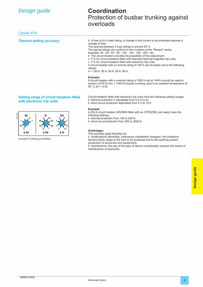
K9AE31000
DD
2106
03
9Schneider Eletric
Des
ign
gu
ide
Design guide CoordinationProtection of busbar trunking against overloads
Thermal setting accuracy A fuse is for a fi xed rating, a change in the current to be protected requires a change of fuse. The spacing between 2 fuse ratings is around 25 %. The typical ratings are conform to the numbers of the “Renard” series.Example: 40 - 50 - 63 - 80 - 100 - 125 - 160 - 200 - etc.
The circuit breaker provides the possibility of fi ne adjustment:5 % for circuit breakers fi tted with standard thermal-magnetic trip units,3 % for circuit breakers fi tted with electronic trip units.
A circuit breaker with a nominal rating of 100 A can be easily set to the following values:Ir = 100 A, 95 A, 90 A, 85 A, 80 A.
Example:A circuit breaker with a nominal rating of 1600 A set at 1440 A would be used to protect a KTA16 (Inc = 1440 A) busbar trunking used in an ambient temperature of 50° C (k1 = 0.9).
b
bvv
Setting range of circuit breakers fi tted with electronic trip units
Circuit breakers fi tted with electronic trip units have the following setting ranges:thermal protection Ir adjustable from 0.4 In to In,short-circuit protection adjustable from 2 Ir to 10 Ir
Example:A 250 A circuit breaker (NS250N fi tted with an STR22SE) can easily have the following settings:
thermal protection from 100 to 250 A,short-circuit protection from 200 to 2500 A.
AvdantagesThis provides great fl exibility for:
modifi cations (fl exibility), extensions (installation changes): the protective devices easily adapt to the load to be protected and to the earthing system (protection of personnel and equipment),
maintenance, the use of this type of device considerably reduces the stocks of maintenance components.
bb
bb
b
b
Example of setting possibilities
Canalis KTA
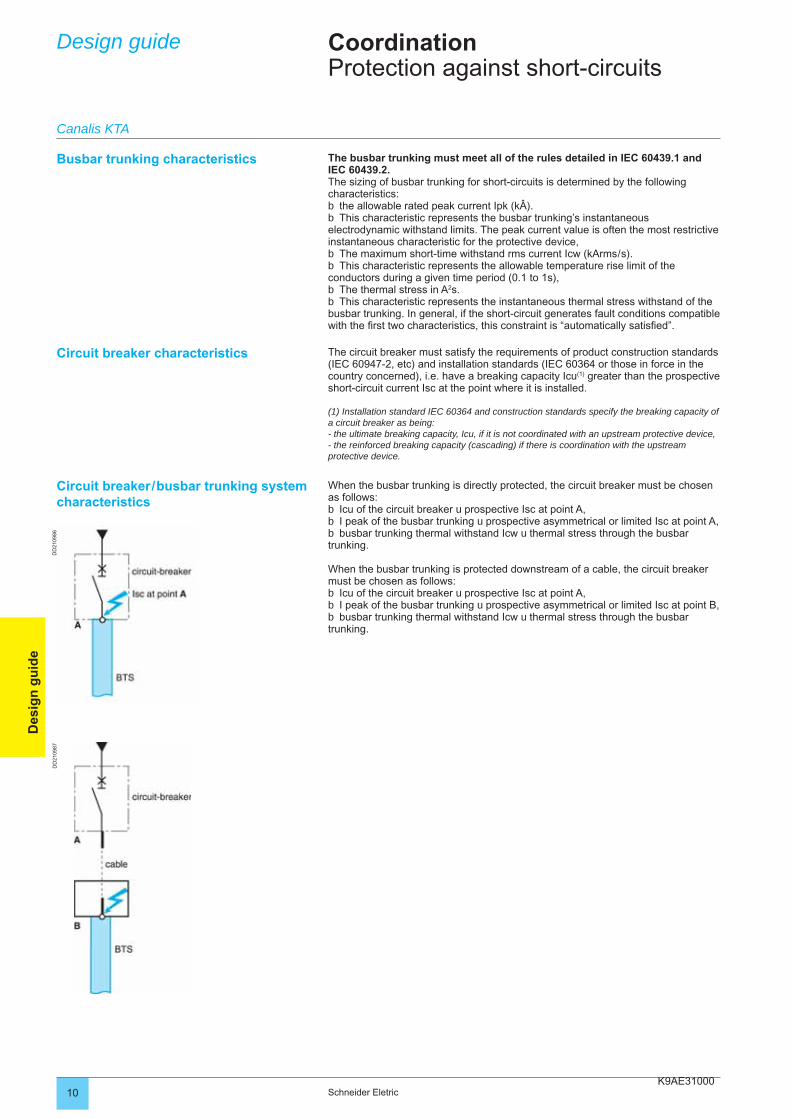
K9AE3100010 Schneider Eletric
Des
ign
gu
ide
Design guide CoordinationProtection against short-circuits
Busbar trunking characteristics The busbar trunking must meet all of the rules detailed in IEC 60439.1 and IEC 60439.2.The sizing of busbar trunking for short-circuits is determined by the following characteristics:
the allowable rated peak current Ipk (kÂ).This characteristic represents the busbar trunking’s instantaneous
electrodynamic withstand limits. The peak current value is often the most restrictive instantaneous characteristic for the protective device,
The maximum short-time withstand rms current Icw (kArms / s).This characteristic represents the allowable temperature rise limit of the
conductors during a given time period (0.1 to 1s),The thermal stress in A2s.This characteristic represents the instantaneous thermal stress withstand of the
busbar trunking. In general, if the short-circuit generates fault conditions compatible with the fi rst two characteristics, this constraint is “automatically satisfi ed”.
bb
bb
bb
Circuit breaker characteristics The circuit breaker must satisfy the requirements of product construction standards (IEC 60947-2, etc) and installation standards (IEC 60364 or those in force in the country concerned), i.e. have a breaking capacity Icu(1) greater than the prospective short-circuit current Isc at the point where it is installed.
(1) Installation standard IEC 60364 and construction standards specify the breaking capacity of a circuit breaker as being:- the ultimate breaking capacity, Icu, if it is not coordinated with an upstream protective device,- the reinforced breaking capacity (cascading) if there is coordination with the upstream protective device.
Circuit breaker / busbar trunking system characteristics
When the busbar trunking is directly protected, the circuit breaker must be chosen as follows:
Icu of the circuit breaker u prospective Isc at point A,I peak of the busbar trunking u prospective asymmetrical or limited Isc at point A,busbar trunking thermal withstand Icw u thermal stress through the busbar
trunking.
When the busbar trunking is protected downstream of a cable, the circuit breaker must be chosen as follows:
Icu of the circuit breaker u prospective Isc at point A,I peak of the busbar trunking u prospective asymmetrical or limited Isc at point B,busbar trunking thermal withstand Icw u thermal stress through the busbar
trunking.
bbb
bbb
Canalis KTA
DD
2109
86D
D21
0987
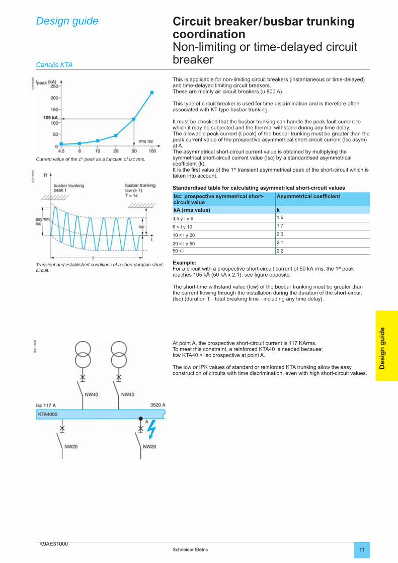
K9AE3100011Schneider Eletric
Des
ign
gu
ide
Design guide Circuit breaker / busbar trunking coordinationNon-limiting or time-delayed circuit breaker
This is applicable for non-limiting circuit breakers (instantaneous or time-delayed) and time-delayed limiting circuit breakers. These are mainly air circuit breakers (u 800 A).
This type of circuit breaker is used for time discrimination and is therefore often associated with KT type busbar trunking.
It must be checked that the busbar trunking can handle the peak fault current to which it may be subjected and the thermal withstand during any time delay.The allowable peak current (I peak) of the busbar trunking must be greater than the peak current value of the prospective asymmetrical short-circuit current (Isc asym) at A.The asymmetrical short-circuit current value is obtained by multiplying the symmetrical short-circuit current value (Isc) by a standardised asymmetrical coeffi cient (k).It is the fi rst value of the 1st transient asymmetrical peak of the short-circuit which is taken into account.
Standardised table for calculating asymmetrical short-circuit values
Isc: prospective symmetrical short-circuit value
Asymmetrical coeffi cient
kA (rms value) k
4,5 y I y 6 1.5
6 < I y 10 1.7
10 < I y 20 2.0
20 < I y 50 2.1
50 < I 2.2
Example:For a circuit with a prospective short-circuit current of 50 kA rms, the 1st peak reaches 105 k (50 kA x 2.1), see fi gure opposite.
The short-time withstand value (Icw) of the busbar trunking must be greater than the current fl owing through the installation during the duration of the short-circuit (Isc) (duration T - total breaking time - including any time delay).
At point A, the prospective short-circuit current is 117 KArms.To meet this constraint, a reinforced KTA40 is needed because:Icw KTA40 > Isc prospective at point A.
The Icw or IPK values of standard or reinforced KTA trunking allow the easy construction of circuits with time discrimination, even with high short-circuit values.
Canalis KTA
Current value of the 1st peak as a function of Isc rms.
Transient and established conditions of a short duration short-circuit.
DD
2109
88D
D21
0989
DD
2109
90
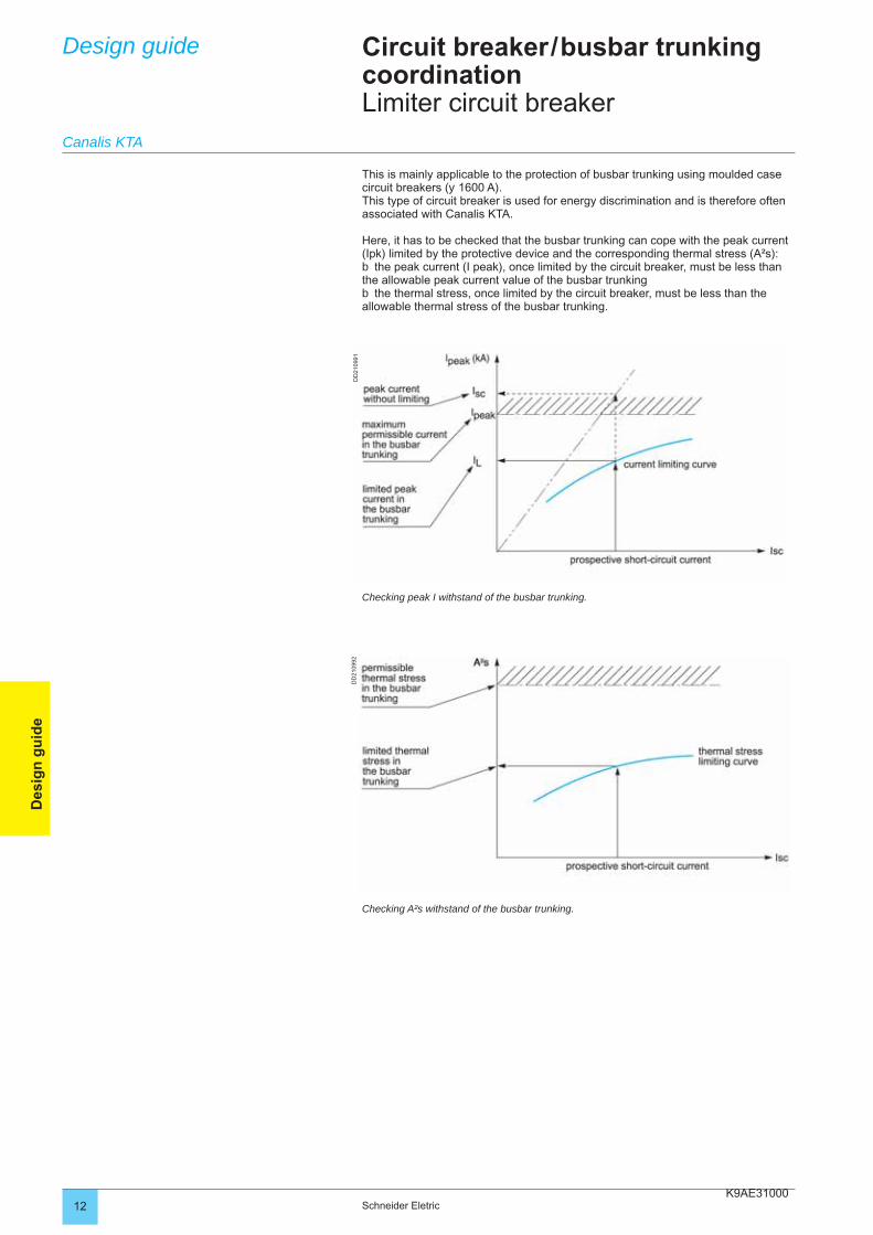
K9AE3100012 Schneider Eletric
Des
ign
gu
ide
Circuit breaker / busbar trunking coordinationLimiter circuit breaker
Design guide
This is mainly applicable to the protection of busbar trunking using moulded case circuit breakers (y 1600 A).This type of circuit breaker is used for energy discrimination and is therefore often associated with Canalis KTA.
Here, it has to be checked that the busbar trunking can cope with the peak current (Ipk) limited by the protective device and the corresponding thermal stress (A²s):
the peak current (I peak), once limited by the circuit breaker, must be less than the allowable peak current value of the busbar trunking
the thermal stress, once limited by the circuit breaker, must be less than the allowable thermal stress of the busbar trunking.
b
b
Checking peak I withstand of the busbar trunking.
Checking A²s withstand of the busbar trunking.
Canalis KTA
DD
2109
92D
D21
0991
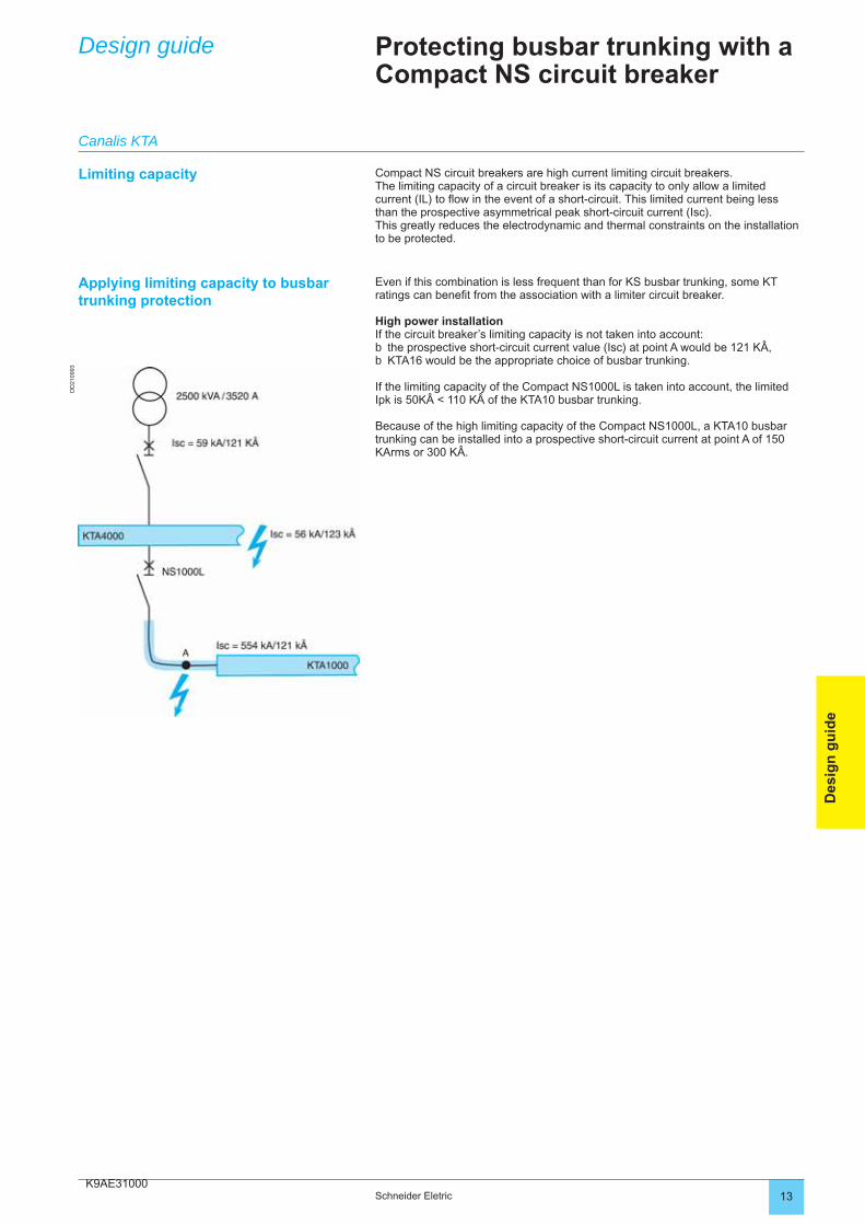
K9AE3100013Schneider Eletric
Des
ign
gu
ide
Design guide Protecting busbar trunking with a Compact NS circuit breaker
Limiting capacity Compact NS circuit breakers are high current limiting circuit breakers.The limiting capacity of a circuit breaker is its capacity to only allow a limited current (IL) to fl ow in the event of a short-circuit. This limited current being less than the prospective asymmetrical peak short-circuit current (Isc).This greatly reduces the electrodynamic and thermal constraints on the installation to be protected.
Applying limiting capacity to busbar trunking protection
Even if this combination is less frequent than for KS busbar trunking, some KT ratings can benefi t from the association with a limiter circuit breaker.
High power installationIf the circuit breaker’s limiting capacity is not taken into account:
the prospective short-circuit current value (Isc) at point A would be 121 KÂ,KTA16 would be the appropriate choice of busbar trunking.
If the limiting capacity of the Compact NS1000L is taken into account, the limited Ipk is 50KÂ < 110 KÂ of the KTA10 busbar trunking.
Because of the high limiting capacity of the Compact NS1000L, a KTA10 busbar trunking can be installed into a prospective short-circuit current at point A of 150 KArms or 300 KÂ.
bb
Canalis KTA
DD
2109
93
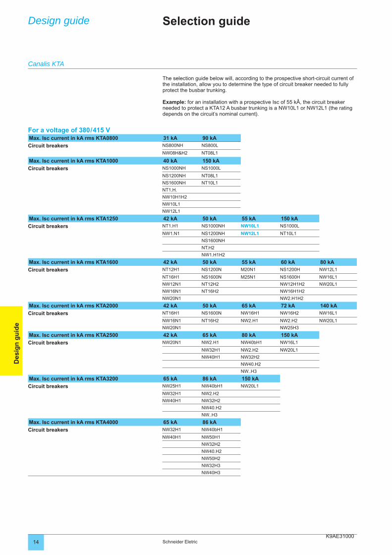
K9AE3100014 Schneider Eletric
Des
ign
gu
ide
Design guide Selection guide
The selection guide below will, according to the prospective short-circuit current of the installation, allow you to determine the type of circuit breaker needed to fully protect the busbar trunking.
Example: for an installation with a prospective Isc of 55 kÂ, the circuit breaker needed to protect a KTA12 A busbar trunking is a NW10L1 or NW12L1 (the rating depends on the circuit’s nominal current).
For a voltage of 380 / 415 VMax. Isc current in kA rms KTA0800 31 kA 90 kA
Circuit breakers NS800NH NS800L
NW08H&H2 NT08L1
Max. Isc current in kA rms KTA1000 40 kA 150 kA
Circuit breakers NS1000NH NS1000L
NS1200NH NT08L1
NS1600NH NT10L1
NT1.H.
NW10H1H2
NW10L1
NW12L1
Max. Isc current in kA rms KTA1250 42 kA 50 kA 55 kA 150 kA
Circuit breakers NT1.H1 NS1000NH NW10L1 NS1000L
NW1.N1 NS1200NH NW12L1 NT10L1
NS1600NH
NT.H2
NW1.H1H2
Max. Isc current in kA rms KTA1600 42 kA 50 kA 55 kA 60 kA 80 kA
Circuit breakers NT12H1 NS1200N M20N1 NS1200H NW12L1
NT16H1 NS1600N M25N1 NS1600H NW16L1
NW12N1 NT12H2 NW12H1H2 NW20L1
NW16N1 NT16H2 NW16H1H2
NW20N1 NW2.H1H2
Max. Isc current in kA rms KTA2000 42 kA 50 kA 65 kA 72 kA 140 kA
Circuit breakers NT16H1 NS1600N NW16H1 NW16H2 NW16L1
NW16N1 NT16H2 NW2.H1 NW2.H2 NW20L1
NW20N1 NW25H3
Max. Isc current in kA rms KTA2500 42 kA 65 kA 80 kA 150 kA
Circuit breakers NW20N1 NW2.H1 NW40bH1 NW16L1
NW32H1 NW2.H2 NW20L1
NW40H1 NW32H2
NW40.H2
NW..H3
Max. Isc current in kA rms KTA3200 65 kA 86 kA 150 kA
Circuit breakers NW25H1 NW40bH1 NW20L1
NW32H1 NW2.H2
NW40H1 NW32H2
NW40.H2
NW..H3
Max. Isc current in kA rms KTA4000 65 kA 86 kA
Circuit breakers NW32H1 NW40bH1
NW40H1 NW50H1
NW32H2
NW40.H2
NW50H2
NW32H3
NW40H3
Canalis KTA
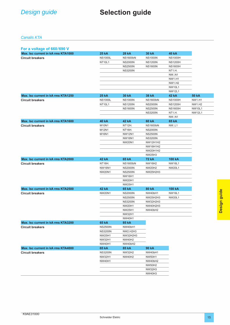
K9AE3100015Schneider Eletric
Des
ign
gu
ide
Design guide Selection guide
Canalis KTA
For a voltage of 660 / 690 VMax. Isc current in kA rms KTA1000 25 kA 28 kA 30 kA 40 kA
Circuit breakers NS1000L NS1600bN NS1000N NS1000H
NT10L1 NS2000N NS1200N NS1200H
NS2500N NS1600N NS1600H
NS3200N NT1.H.
NW..N1
NW1.H1
NW1.H2
NW10L1
NW12L1
Max. Isc current in kA rms KTA1250 25 kA 30 kA 38 kA 42 kA 50 kA
Circuit breakers NS1000L NS1000N NS1600bN NS1000H NW1.H1
NT10L1 NS1200N NS2000N NS1200H NW1.H2
NS1600N NS2500N NS1600H NW10L1
NS3200N NT1.H. NW12L1
NW..N1
Max. Isc current in kA rms KTA1600 40 kA 42 kA 60 kA 65 kA
Circuit breakers M10N1 NT12H. NS1600bN NW..L1
M12N1 NT16H. NS2000N
M16N1 NW12N1 NS2500N
NW16N1 NS3200N
NW20N1 NW12H1H2
NW16H1H2
NW20H1H2
NW25H3
Max. Isc current in kA rms KTA2000 42 kA 65 kA 72 kA 100 kA
Circuit breakers NT16H. NS1600bN NW16H2 NW16L1
NW16N1 NS2000N NW20H2 NW20L1
NW20N1 NS2500N NW25H2H3
NW16H1
NW20H1
NW25H1
Max. Isc current in kA rms KTA2500 42 kA 65 kA 80 kA 100 kA
Circuit breakers NW20N1 NS2000N NW40bH1 NW16L1
NS2500N NW25H2H3 NW20L1
NS3200N NW32H2H3
NW20H1 NW40H2H3
NW25H1 NW40bH2
NW32H1
NW40H1
Max. Isc current in kA rms KTA3200 65 kA 85 kA
Circuit breakers NS2500N NW40bH1
NS3200N NW2.H2H3
NW25H1 NW32H2H3
NW32H1 NW40H2
NW40H1 NW40bH2
Max. Isc current in kA rms KTA4000 65 kA 85 kA 90 kA
Circuit breakers NS3200N NW32H2 NW40bH1
NW32H1 NW40H2 NW50H1
NW40H1 NW40bH2
NW50H2
NW32H3
NW40H3
K9AE320002 Schneider Electric
Des
ign
gu
ide
Design guide
Canalis KTA
Degree of protection
Standard IEC 60529 (February 2001) indicates the degree of protection provided by electrical equipment enclosures against accidental direct contact with live parts and against the ingress of solid foreign objects or water.
This standard does not apply to protection against the risk of explosion or conditions such as humidity, corrosive gases, fungi or vermin.
The IP code comprises 2 characteristic numerals and may include an additional letter when the actual protection of persons against direct contact with live parts is better than that indicated by the fi rst numeral.
The fi rst numeral characterises the protection of the equipment against penetration of solid objects and the protection of people.The second numeral characterises the protection of the equipment against penetration of water with harmful effects.
Remarks concerning the degree of protection IPThe degree of protection IP must always be read and understood numeral by numeral and not as a whole.For example, an IP31 enclosure is suitable for an environment that requires a minimum degree of protection IP21. However an IP30 wall-mount enclosure is not suitable.
The degrees of protection indicated in this catalogue are valid for the enclosures as presented. However, the indicated degree of protection is guaranteed only when the installation and device mounting are carried out in accordance with professional standard practice.
Additional letterProtection of persons against direct contact with live parts.
The additional letter is used only if the actual protection of persons is higher than that indicated by the fi rst characteristic numeral of the IP code.If only the protection of persons is of interest, the two characteristic numerals are replaced by the letter “X”, e.g. IPxxB.
Degree of protection IK Standard IEC 62-262 defi nes a coding system (IK code) indicating the degree of protection provided by electrical equipment enclosures against external mechanical impact.
Installation standard IEC 60-364 provides a cross-reference between the various degrees of protection and the environmental conditions classifi cation, relating to the selection of equipment according to external factors.
IK codeppThe IK code comprises 2 characteristic numerals (e.g. IK05).
Practical guide UTE C 15-103 shows, in the form of tables, the characteristics required for electrical equipment (including minimum degrees of protection), according to the locations in which they are installed.
Standard IEC 60364-5-51 categorises a large number of external infl uences to which electrical installations can be subjected, for instance the presence of water, solid objects, shocks, vibrations and corrosive substances.The importance of these infl uences depends on the installation conditions. For example, the presence of water can vary from a few drops to total immersion.
Degree of protection IP
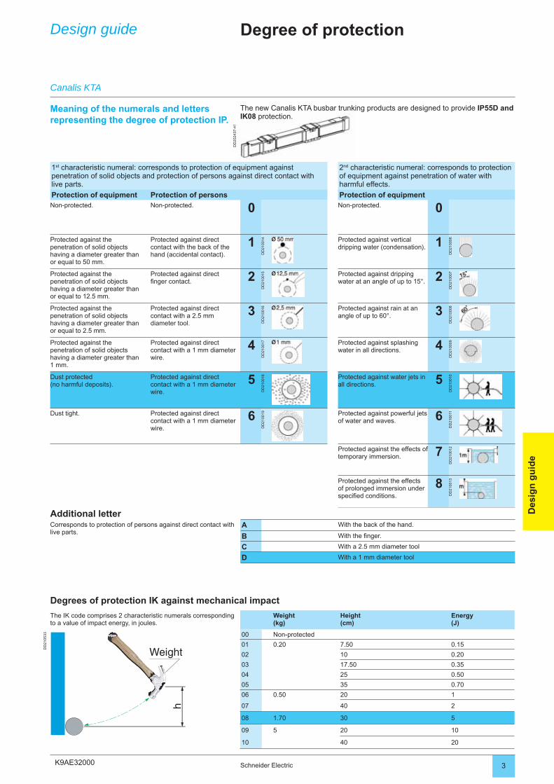
K9AE32000
DD
2024
37-4
1
3Schneider Electric
Des
ign
gu
ide
Design guide
1st characteristic numeral: corresponds to protection of equipment against penetration of solid objects and protection of persons against direct contact with live parts.
2nd characteristic numeral: corresponds to protection of equipment against penetration of water with harmful effects.
Protection of equipment Protection of persons Protection of equipmentNon-protected. Non-protected. 0 Non-protected. 0
Protected against the penetration of solid objects having a diameter greater than or equal to 50 mm.
Protected against direct contact with the back of the hand (accidental contact).
1D
D21
0014 Protected against vertical
dripping water (condensation). 1
DD
2100
06
Protected against the penetration of solid objects having a diameter greater than or equal to 12.5 mm.
Protected against directfi nger contact. 2
DD
2100
15 Protected against dripping water at an angle of up to 15°. 2
DD
2100
07
Protected against the penetration of solid objects having a diameter greater than or equal to 2.5 mm.
Protected against direct contact with a 2.5 mm diameter tool.
3
DD
2100
16 Protected against rain at an angle of up to 60°. 3
DD
2100
08
Protected against the penetration of solid objects having a diameter greater than 1 mm.
Protected against direct contact with a 1 mm diameter wire.
4
DD
2100
17 Protected against splashing water in all directions. 4
DD
2100
09
Dust protected(no harmful deposits).
Protected against direct contact with a 1 mm diameter wire.
5
DD
2100
18 Protected against water jets in all directions. 5
DD
2100
10
Dust tight. Protected against direct contact with a 1 mm diameter wire.
6
DD
2100
19 Protected against powerful jets of water and waves. 6
DD
2100
11Protected against the effects of temporary immersion. 7
DD
2100
12
Protected against the effects of prolonged immersion under specifi ed conditions.
8
DD
2100
13
Additional letterCorresponds to protection of persons against direct contact with live parts.
A With the back of the hand.
B With the fi nger.
C With a 2.5 mm diameter tool
D With a 1 mm diameter tool
Degrees of protection IK against mechanical impact
The IK code comprises 2 characteristic numerals corresponding to a value of impact energy, in joules.
Weight(kg)
Height(cm)
Energy(J)
DD
2105
33 00 Non-protected
01 0.20 7.50 0.15
02 10 0.20
03 17.50 0.35
04 25 0.50
05 35 0.70
06 0.50 20 1
07 40 2
08 1.70 30 5
09 5 20 10
10 40 20
The new Canalis KTA busbar trunking products are designed to provide IP55D and IK08 protection.
Meaning of the numerals and letters representing the degree of protection IP.
Degree of protection
Canalis KTA
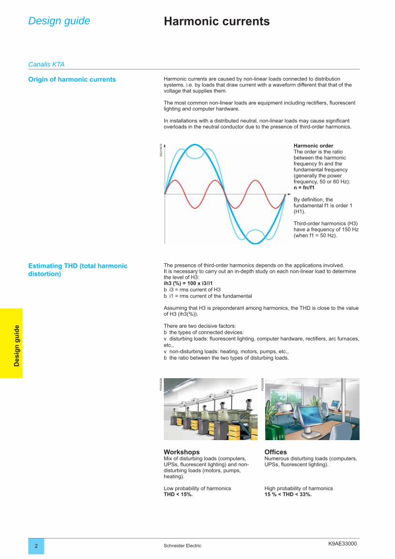
K9AE33000
DD
2106
79P
D20
2028
PD
2020
29
2 Schneider Electric
Des
ign
gu
ide
Design guide Harmonic currents
Harmonic currents are caused by non-linear loads connected to distribution systems, i.e. by loads that draw current with a waveform different that that of the voltage that supplies them.
The most common non-linear loads are equipment including rectifi ers, fl uorescent lighting and computer hardware. In installations with a distributed neutral, non-linear loads may cause signifi cant overloads in the neutral conductor due to the presence of third-order harmonics.
Harmonic orderThe order is the ratio between the harmonic frequency fn and the fundamental frequency (generally the power frequency, 50 or 60 Hz):n = fn / f1
By defi nition, the fundamental f1 is order 1 (H1).
Third-order harmonics (H3) have a frequency of 150 Hz (when f1 = 50 Hz).
The presence of third-order harmonics depends on the applications involved.It is necessary to carry out an in-depth study on each non-linear load to determine the level of H3: ih3 (%) = 100 x i3 / i1
i3 = rms current of H3i1 = rms current of the fundamental
Assuming that H3 is preponderant among harmonics, the THD is close to the value of H3 (ih3(%)).
There are two decisive factors:the types of connected devices: disturbing loads: fl uorescent lighting, computer hardware, rectifi ers, arc furnaces,
etc.,non-disturbing loads: heating, motors, pumps, etc.,the ratio between the two types of disturbing loads.
bb
bv
vb
WorkshopsMix of disturbing loads (computers, UPSs, fl uorescent lighting) and non-disturbing loads (motors, pumps, heating).
Low probability of harmonicsTHD < 15%.
Offi cesNumerous disturbing loads (computers,UPSs, fl uorescent lighting).
High probability of harmonics15 % < THD < 33%.
Origin of harmonic currents
Estimating THD (total harmonic distortion)
Canalis KTA
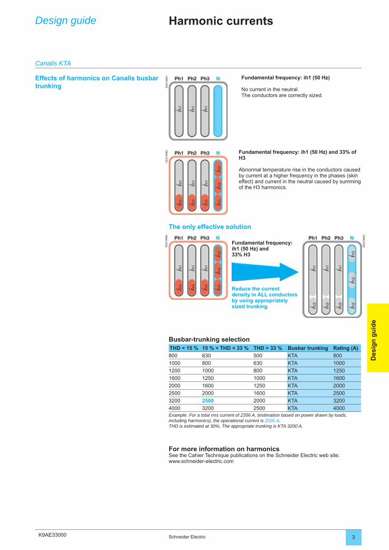
K9AE33000
DD
2106
81D
D21
0680
DD
2106
80
DD
2106
83
3Schneider Electric
Des
ign
gu
ide
Design guide Harmonic currents
Effects of harmonics on Canalis busbar trunking
Fundamental frequency: ih1 (50 Hz)
No current in the neutral. The conductors are correctly sized.
Fundamental frequency: ih1 (50 Hz) and 33% of H3
Abnormal temperature rise in the conductors caused by current at a higher frequency in the phases (skin effect) and current in the neutral caused by summing of the H3 harmonics.
Fundamental frequency:ih1 (50 Hz) and33% H3
Reduce the current density in ALL conductors by using appropriately sized trunking.
Busbar-trunking selectionTHD < 15 % 15 % < THD < 33 % THD > 33 % Busbar trunking Rating (A)
800 630 500 KTA 800
1000 800 630 KTA 1000
1200 1000 800 KTA 1250
1600 1250 1000 KTA 1600
2000 1600 1250 KTA 2000
2500 2000 1600 KTA 2500
3200 2500 2000 KTA 3200
4000 3200 2500 KTA 4000Example. For a total rms current of 2356 A, (estimation based on power drawn by loads, including harmonics), the operational current is 2500 A.THD is estimated at 30%. The appropriate trunking is KTA 3200 A.
For more information on harmonicsSee the Cahier Technique publications on the Schneider Electric web site:www.schneider-electric.com
Canalis KTA
The only effective solution
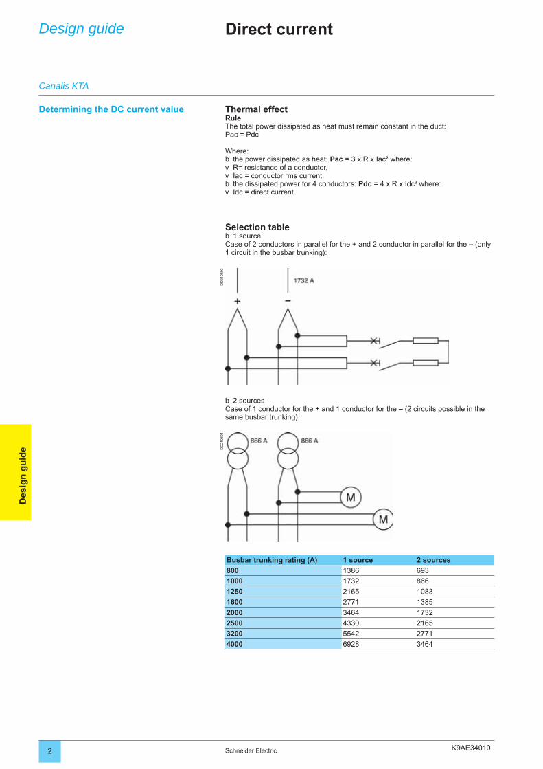
K9AE34010
DD
2108
93D
D21
0894
2 Schneider Electric
Des
ign
gu
ide
Design guide Direct current
Determining the DC current value Thermal effectRuleThe total power dissipated as heat must remain constant in the duct:Pac = Pdc
Where: the power dissipated as heat: Pac = 3 x R x Iac² where:R= resistance of a conductor,Iac = conductor rms current,the dissipated power for 4 conductors: Pdc = 4 x R x Idc² where:Idc = direct current.
Selection table1 source
Case of 2 conductors in parallel for the + and 2 conductor in parallel for the – (only 1 circuit in the busbar trunking):
bvvbv
b
Busbar trunking rating (A) 1 source 2 sources
800 1386 693
1000 1732 866
1250 2165 1083
1600 2771 1385
2000 3464 1732
2500 4330 2165
3200 5542 2771
4000 6928 3464
2 sourcesCase of 1 conductor for the + and 1 conductor for the – (2 circuits possible in the same busbar trunking):
b
Canalis KTA
K9AE34010 3Schneider Electric
Des
ign
gu
ide
Design guide Direct current
ProtectionWith DC, there is no zero crossing point of the voltage and current to facilitate arc extinction in the protective device. The arcing time is longer and the energy that has to be absorbed is higher than for AC.The voltage of the DC arc must rise to the source voltage very quickly in order to “put out” the short-circuit current.“Shortened” electrical equation: U network = R x Isc + Uarc where:
Isc = U network - Uarc,R = 0 when Uarc = U network.
Use with specifi c switchgearA quick rise in arcing voltage can be achieved by using series fuses, one fuse on the + and one fuse on the – of each circuit.For some current rating and fuse characteristics, the placing of two fuses in series on each polarity may be specifi ed (highly inductive circuit).In some cases, two fuses must be placed in parallel for each polarity.
bb
Canalis KTA
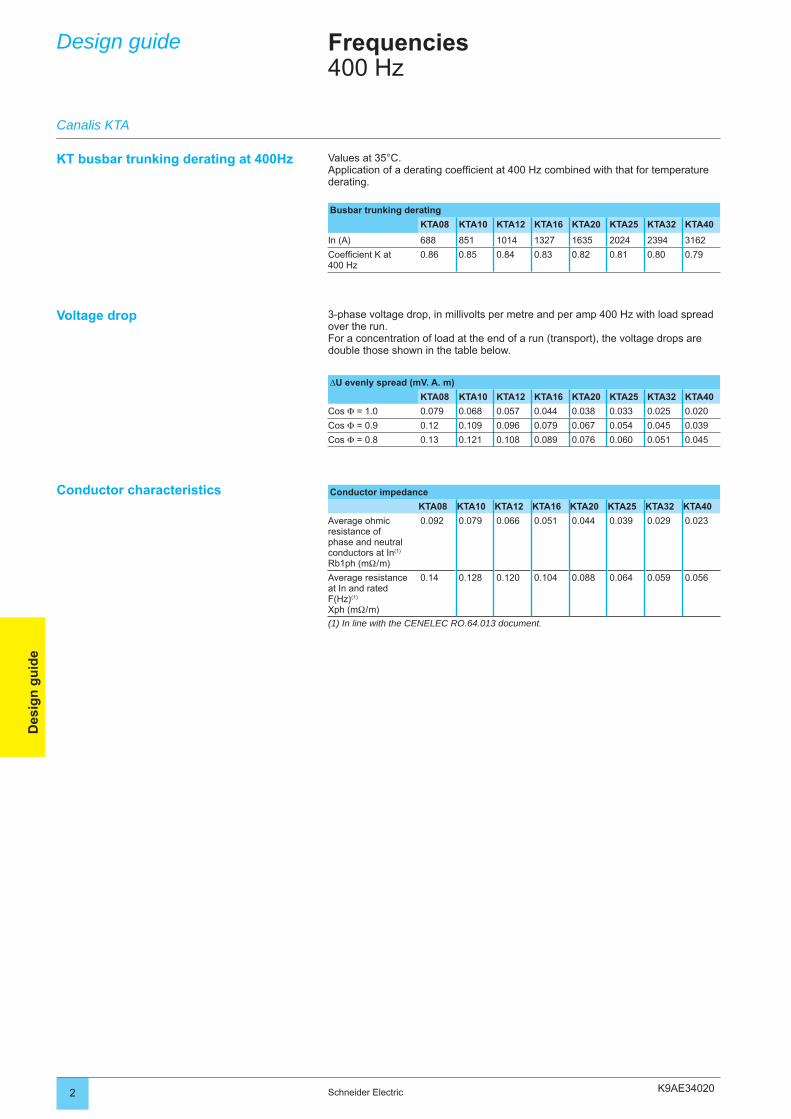
2 Schneider Electric
Des
ign
gu
ide
Design guide Frequencies400 Hz
KT busbar trunking derating at 400Hz
Conductor impedance
KTA08 KTA10 KTA12 KTA16 KTA20 KTA25 KTA32 KTA40
Average ohmic resistance of phase and neutral conductors at In(1) Rb1ph (mΩ / m)
0.092 0.079 0.066 0.051 0.044 0.039 0.029 0.023
Average resistance at In and rated F(Hz)(1)
Xph (mΩ / m)
0.14 0.128 0.120 0.104 0.088 0.064 0.059 0.056
(1) In line with the CENELEC RO.64.013 document.
3-phase voltage drop, in millivolts per metre and per amp 400 Hz with load spread over the run. For a concentration of load at the end of a run (transport), the voltage drops are double those shown in the table below.
∆U evenly spread (mV. A. m)
KTA08 KTA10 KTA12 KTA16 KTA20 KTA25 KTA32 KTA40
Cos Φ = 1.0 0.079 0.068 0.057 0.044 0.038 0.033 0.025 0.020
Cos Φ = 0.9 0.12 0.109 0.096 0.079 0.067 0.054 0.045 0.039
Cos Φ = 0.8 0.13 0.121 0.108 0.089 0.076 0.060 0.051 0.045
Values at 35°C.Application of a derating coeffi cient at 400 Hz combined with that for temperature derating.
Busbar trunking derating
KTA08 KTA10 KTA12 KTA16 KTA20 KTA25 KTA32 KTA40
In (A) 688 851 1014 1327 1635 2024 2394 3162
Coeffi cient K at 400 Hz
0.86 0.85 0.84 0.83 0.82 0.81 0.80 0.79
Voltage drop
Conductor characteristics
Canalis KTA
K9AE34020
3Schneider Electric
Des
ign
gu
ide
K9AE34020
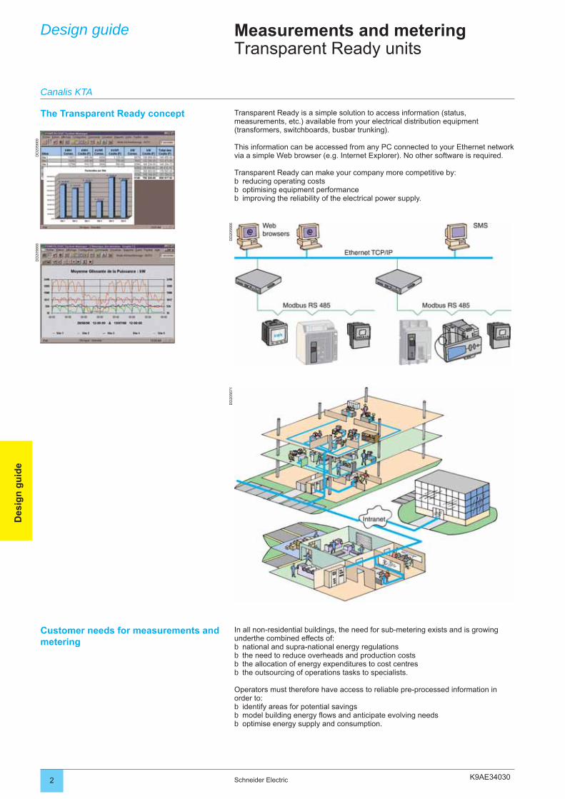
K9AE34030
DD
2056
69D
D20
5668
DD
2056
66D
D20
5671
2 Schneider Electric
Des
ign
gu
ide
Design guide Measurements and meteringTransparent Ready units
The Transparent Ready concept Transparent Ready is a simple solution to access information (status, measurements, etc.) available from your electrical distribution equipment (transformers, switchboards, busbar trunking).
This information can be accessed from any PC connected to your Ethernet network via a simple Web browser (e.g. Internet Explorer). No other software is required.
Transparent Ready can make your company more competitive by:reducing operating costsoptimising equipment performanceimproving the reliability of the electrical power supply.
bbb
Customer needs for measurements and metering
In all non-residential buildings, the need for sub-metering exists and is growing underthe combined effects of:
national and supra-national energy regulationsthe need to reduce overheads and production coststhe allocation of energy expenditures to cost centresthe outsourcing of operations tasks to specialists.
Operators must therefore have access to reliable pre-processed information in order to:
identify areas for potential savingsmodel building energy fl ows and anticipate evolving needsoptimise energy supply and consumption.
bbbb
bbb
Canalis KTA
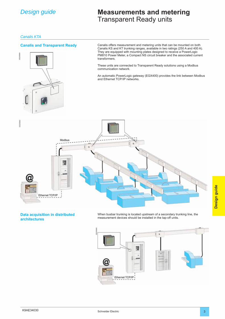
K9AE34030
DD
2056
64D
D20
5663
DD
2056
65
3Schneider Electric
Des
ign
gu
ide
Design guide Measurements and meteringTransparent Ready units
Canalis and Transparent Ready Canalis offers measurement and metering units that can be mounted on both Canalis KS and KT trunking ranges, available in two ratings (250 A and 400 A).They are equipped with mounting plates designed to receive a PowerLogic PM810 Power Meter, a Compact NS circuit breaker and the associated current transformers.
These units are connected to Transparent Ready solutions using a Modbus communication network.
An automatic PowerLogic gateway (EGX400) provides the link between Modbus and Ethernet TCP / IP networks.
Data acquisition in distributed architectures
When busbar trunking is located upstream of a secondary trunking line, themeasurement devices should be installed in the tap-off units.
Canalis KTA
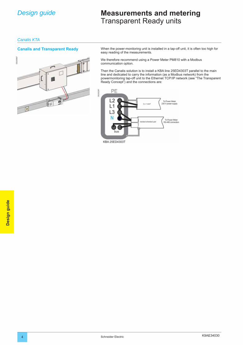
K9AE34030
DD
2056
67
DD
2022
87
4 Schneider Electric
Des
ign
gu
ide
Design guide Measurements and meteringTransparent Ready units
Canalis and Transparent Ready When the power-monitoring unit is installed in a tap-off unit, it is often too high for easy reading of the measurements.
We therefore recommend using a Power Meter PM810 with a Modbus communication option.
Then the Canalis solution is to install a KBA line 25ED4303T parallel to the main line and dedicated to carry the information (as a Modbus network) from the powermonitoring tap-off unit to the Ethernet TCP / IP network (see “The Transparent Ready Concept”) and the connections are:
Canalis KTA
K9AE34030 5Schneider Electric
Des
ign
gu
ide
Design guide Measurements and metering
Canalis KTA
K9AE350002 Schneider Electric
Des
ign
gu
ide
Design guide Fire resistance
Insulating material resistance test to abnormal temperatures
ObjectiveTo check a material will not be suspected as being the origin of a secondary fi re outbreak.
As defi ned in standards § 8.2.13 IEC 60439-2 and IEC 60695-2-10 and 2-13.
MethodApplication of an incandescent wire at 960°C for 30 seconds on the insulating materials in contact with live parts.
Result criteriaThe specimen is considered to have passed the incandescent wire test if:
if there is no visible fl ame and no sustained incandescence,the specimen’s fl ames and incandescence go out within 30 seconds of the
incandescent wire being removed.
Flame propagation resistance test
ObjectiveTo check a busbar trunking will not create secondary fi re outbreaks.
As defi ned in standards § 8.2.14 IEC 60439-2 and IEC 60332 part 3.
MethodApplication of a fl ame at 800°C for 40 minutes on a straight length of busbar
trunking whose centre is located 2.5 metres from the edge of the burner.
Result criteriaThe specimen is considered to have passed the test if:
combustion does not occur,the maximum extent of the burned part (external and internal) of the busbar
trunking does not go beyond 2.5 metres above the lower edge of the burner.
bb
b
bb
Defi nition of tests
As required by standards, Canalis KT busbar trunking complies with:material resistance to abnormal temperatures,fl ame propagation resistance,2 hour fi re barrier function when going through a partition wall,conservation of all circuits for 1 h 30.
bbbb
Canalis KTA
K9AE35000 3Schneider Electric
Des
ign
gu
ide
Design guide Fire resistance
Fire barrier test through a partition wall
ObjectiveTo check a busbar trunking will not propagate a fi re from one room to another by crossing a fi re barrier wall for 60, 120, 180, or 240 minutes.
MethodThe fi re barrier busbar trunking section to be tested is placed in an oven which executes a standardised temperature-time curve (EN 1366-3).
Result criteriaThe specimen is considered to have passed the test if:
there are no fl ames behind the fi re barrier,there is no smoke or gas behind the fi re barrier (not requested by the standard;
can appear as a remark in the test report),the temperature rise of the casing behind the fi re barrier does not exceed 180°C.
Conservation of all circuits in fi re conditions test
ObjectiveTo check all the busbar trunking’s electrical circuits are preserved in fi re conditions.
MethodIts entire length inserted, the busbar trunking is taken as a specimen in an insulating sheath.
Result criteriaThe specimen is considered to have passed the test if:
conductor continuity is preserved,there is no short-circuit between conductors.
bb
b
bb
Canalis KTA
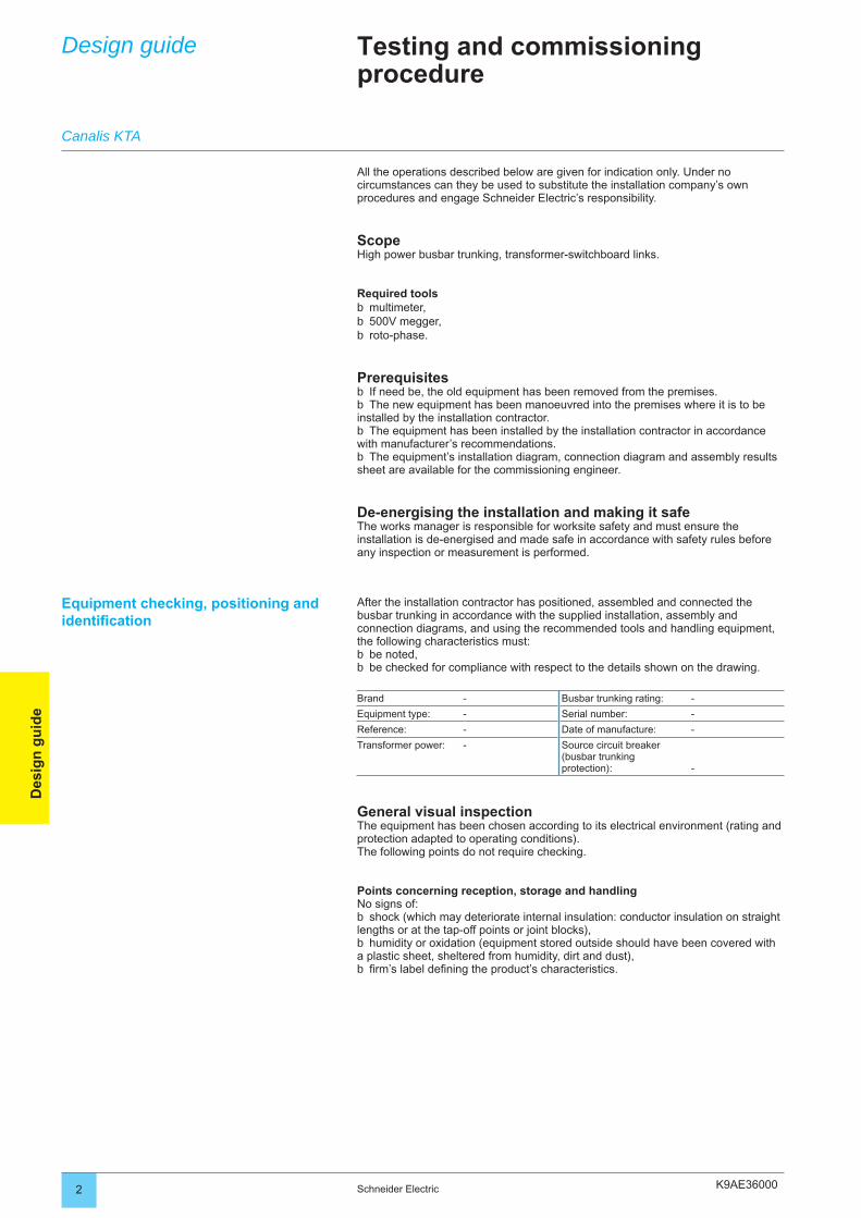
K9AE360002 Schneider Electric
Des
ign
gu
ide
Design guide Testing and commissioning procedure
All the operations described below are given for indication only. Under no circumstances can they be used to substitute the installation company’s own procedures and engage Schneider Electric’s responsibility.
ScopeHigh power busbar trunking, transformer-switchboard links.
Required toolsmultimeter,500V megger,roto-phase.
PrerequisitesIf need be, the old equipment has been removed from the premises.The new equipment has been manoeuvred into the premises where it is to be
installed by the installation contractor.The equipment has been installed by the installation contractor in accordance
with manufacturer’s recommendations.The equipment’s installation diagram, connection diagram and assembly results
sheet are available for the commissioning engineer.
De-energising the installation and making it safeThe works manager is responsible for worksite safety and must ensure the installation is de-energised and made safe in accordance with safety rules before any inspection or measurement is performed.
bbb
bb
b
b
After the installation contractor has positioned, assembled and connected the busbar trunking in accordance with the supplied installation, assembly and connection diagrams, and using the recommended tools and handling equipment, the following characteristics must:
be noted,be checked for compliance with respect to the details shown on the drawing.
Brand - Busbar trunking rating: -
Equipment type: - Serial number: -
Reference: - Date of manufacture: -
Transformer power: - Source circuit breaker (busbar trunking protection): -
General visual inspectionThe equipment has been chosen according to its electrical environment (rating and protection adapted to operating conditions). The following points do not require checking.
Points concerning reception, storage and handlingNo signs of:
shock (which may deteriorate internal insulation: conductor insulation on straight lengths or at the tap-off points or joint blocks),
humidity or oxidation (equipment stored outside should have been covered with a plastic sheet, sheltered from humidity, dirt and dust),fi rm’s label defi ning the product’s characteristics.
bb
b
b
b
Equipment checking, positioning and identifi cation
Canalis KTA
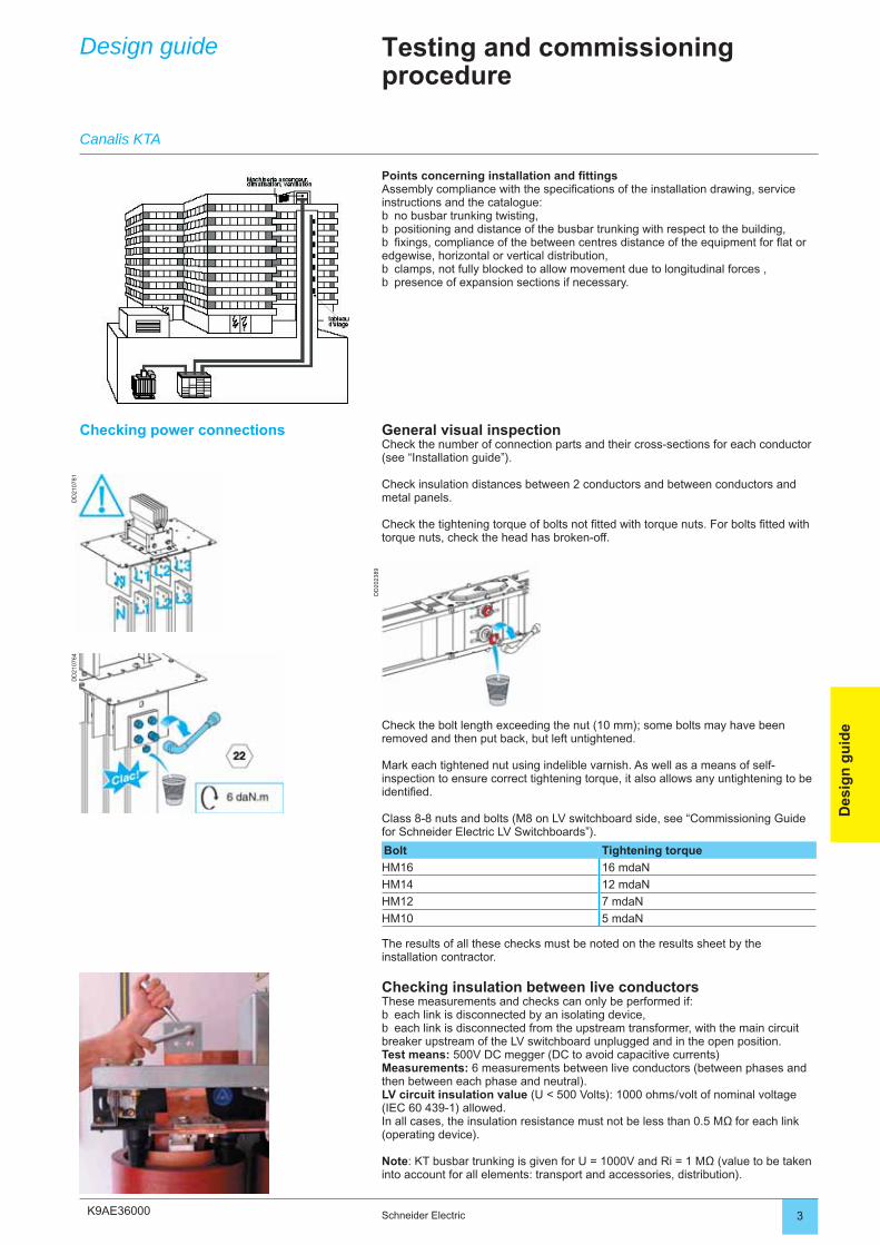
K9AE36000
DD
2107
81D
D21
0764
DD
2023
89
3Schneider Electric
Des
ign
gu
ide
Design guide Testing and commissioning procedure
Points concerning installation and fi ttingsAssembly compliance with the specifi cations of the installation drawing, service instructions and the catalogue:
no busbar trunking twisting,positioning and distance of the busbar trunking with respect to the building,fi xings, compliance of the between centres distance of the equipment for fl at or
edgewise, horizontal or vertical distribution,clamps, not fully blocked to allow movement due to longitudinal forces ,presence of expansion sections if necessary.
bbb
bb
Checking power connections General visual inspectionCheck the number of connection parts and their cross-sections for each conductor (see “Installation guide”).
Check insulation distances between 2 conductors and between conductors and metal panels.
Check the tightening torque of bolts not fi tted with torque nuts. For bolts fi tted with torque nuts, check the head has broken-off.
Canalis KTA
Check the bolt length exceeding the nut (10 mm); some bolts may have been removed and then put back, but left untightened.
Mark each tightened nut using indelible varnish. As well as a means of self-inspection to ensure correct tightening torque, it also allows any untightening to be identifi ed.
Class 8-8 nuts and bolts (M8 on LV switchboard side, see “Commissioning Guide for Schneider Electric LV Switchboards”).
Bolt Tightening torque
HM16 16 mdaN
HM14 12 mdaN
HM12 7 mdaN
HM10 5 mdaN
The results of all these checks must be noted on the results sheet by the installation contractor.
Checking insulation between live conductorsThese measurements and checks can only be performed if:
each link is disconnected by an isolating device,each link is disconnected from the upstream transformer, with the main circuit
breaker upstream of the LV switchboard unplugged and in the open position.Test means: 500V DC megger (DC to avoid capacitive currents)Measurements: 6 measurements between live conductors (between phases and then between each phase and neutral).LV circuit insulation value (U < 500 Volts): 1000 ohms / volt of nominal voltage (IEC 60 439-1) allowed. In all cases, the insulation resistance must not be less than 0.5 MΩ for each link (operating device).
Note: KT busbar trunking is given for U = 1000V and Ri = 1 MΩ (value to be taken into account for all elements: transport and accessories, distribution).
bb
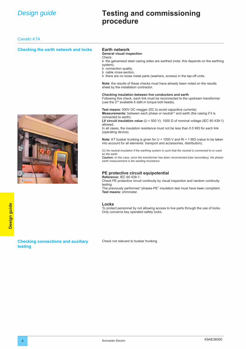
K9AE360004 Schneider Electric
Des
ign
gu
ide
Design guide Testing and commissioning procedure
Checking the earth network and locks Earth networkGeneral visual inspectionCheck:
the galvanised steel casing sides are earthed (note: this depends on the earthing system),
connection quality,cable cross-section,there are no loose metal parts (washers, screws) in the tap-off units.
Note: the results of these checks must have already been noted on the results sheet by the installation contractor.
Checking insulation between live conductors and earthFollowing this check, each link must be reconnected to the upstream transformer (use the 2nd available 6 daN.m torque bolt heads).
Test means: 500V DC megger (DC to avoid capacitive currents)Measurements: between each phase or neutral(1) and earth (the casing if it is connected to earth).LV circuit insulation value (U < 500 V): 1000 Ω of nominal voltage (IEC 60 439-1) allowed. In all cases, the insulation resistance must not be less than 0.5 MΩ for each link (operating device).
Note: KT busbar trunking is given for U = 1000 V and Ri = 1 MΩ (value to be taken into account for all elements: transport and accessories, distribution).
(1) No neutral insulation if the earthing system is such that the neutral is connected to or used as the earth. Caution: In this case, once the transformer has been reconnected (star secondary), the phase-earth measurement is the winding resistance.
PE protective circuit equipotentialReference: IEC 60 439-1:Check PE protective circuit continuity by visual inspection and random continuity testing. The previously performed “phases-PE” insulation test must have been compliant.Test means: ohmmeter.
LocksTo protect personnel by not allowing access to live parts through the use of locks.Only concerns key operated safety locks.
b
bbb
Checking connections and auxiliary testing
Check not relevant to busbar trunking.
Canalis KTA

K9AE36000 5Schneider Electric
Des
ign
gu
ide
Design guide Testing and commissioning procedure
De-energised equipment operating tests Checking source circuit breaker protection settingsCompliance check in accordance with the installation drawing specifi cations:
Imax thermal,In magnetic.
Note: this check is only to be performed if the busbar trunking is commissioned at the same time as the transformer: the source circuit breaker protection setting checks are related to transformer commissioning.Check not relevant if the transformer has already been commissioned.
If this check is successful, the busbar trunking can be commissioned and the energised operating tests performed with the appropriate protective equipment
bb
Commissioning and energised equipment operating tests
NOTE: commissioning can only be carried out by personnel with appropriate authorisations.
Preliminary operation: energising the off-load transformer.Closing the source circuit breaker.
Checking phase orderObjective: to detect, in order to correct, an inversion of the phases or neutral amongst the busbar trunking’s 4 incoming and outgoing connections with respect to the transformer output.
Test means: roto-phase or 3-phase harmonic analyser.
If busbar trunking energising is successful, a progressive start-up of the factory must be requested to defi nitively validate commissioning.
If unsuccessful, the previous checks must be carried out again to try and locate the fault. Before undertaking this, the equipment must once again be made safe.
Final putting into service testThis test is performed once the busbar trunking has been energised. The progressive start-up of loads will highlight any undesirable phenomena due to the increased average load.
Real life operating testOnce the high power busbar trunking has been energised, the other busbar trunking must be gradually put into service starting with those furthest from the load, then each load itself, those with high pull-in currents, then the lighting, contactors, heating, motors, etc.
There must not be excessive vibration, and no sparkovers should be observed.
The test simply consists of checking correct busbar trunking operation according to:
the average number of machines in operation,the load variation of each individual load,the simultaneous operation of machines (superimposing of peaks).
If everything is in order, the busbar trunking is declared “in-service”.Testing is completed.
bbb
Canalis KTA
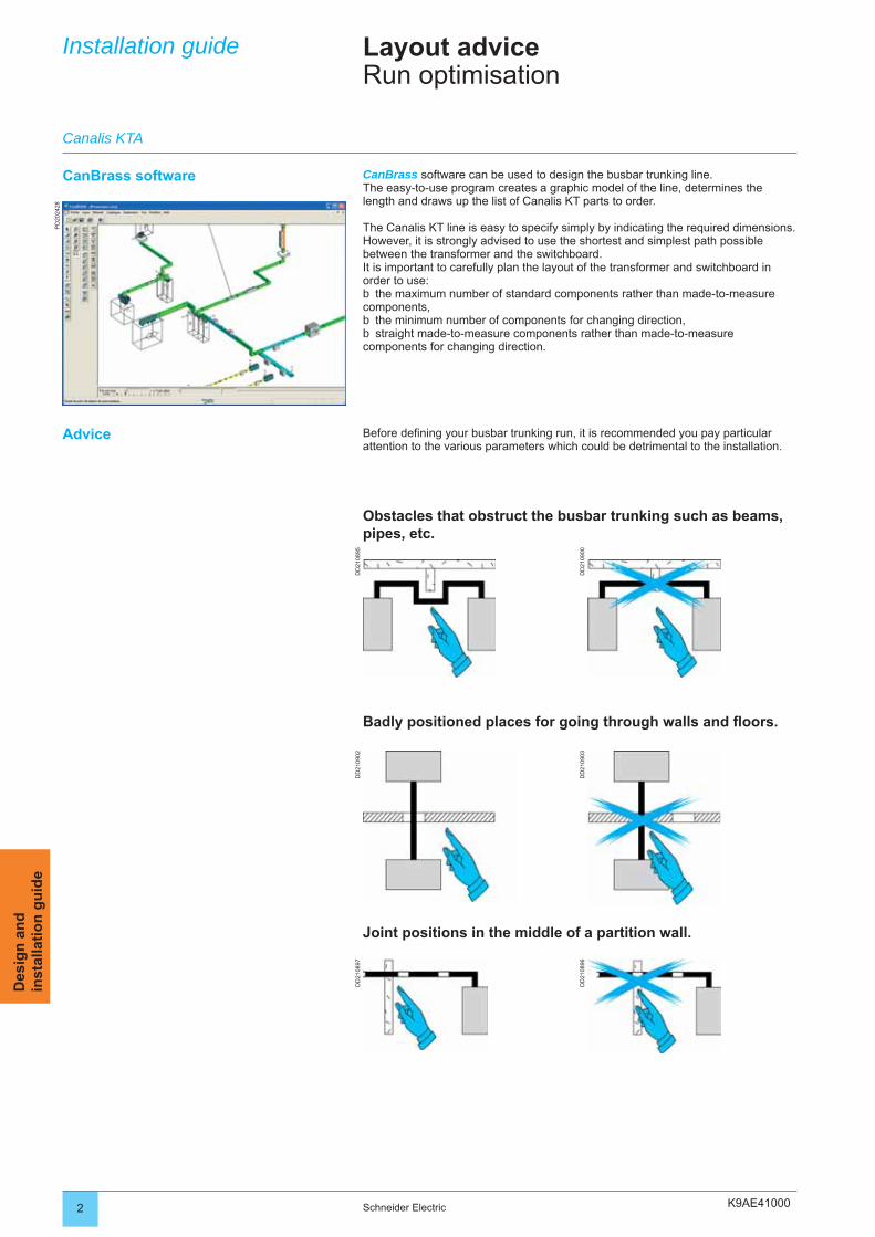
K9AE41000
DD
2108
95
DD
2109
00
DD
2109
02
DD
2109
03
DD
2108
97
DD
2108
96
PD
2024
28
2 Schneider Electric
Des
ign
an
din
stal
lati
on
gu
ideLayout adviceRun optimisation
Installation guide
Canalis KTA
Before defi ning your busbar trunking run, it is recommended you pay particular attention to the various parameters which could be detrimental to the installation.
Obstacles that obstruct the busbar trunking such as beams, pipes, etc.
Badly positioned places for going through walls and fl oors.
Joint positions in the middle of a partition wall.
CanBrass software can be used to design the busbar trunking line.The easy-to-use program creates a graphic model of the line, determines the length and draws up the list of Canalis KT parts to order.
The Canalis KT line is easy to specify simply by indicating the required dimensions.However, it is strongly advised to use the shortest and simplest path possible between the transformer and the switchboard.It is important to carefully plan the layout of the transformer and switchboard in order to use:
the maximum number of standard components rather than made-to-measure components,
the minimum number of components for changing direction,straight made-to-measure components rather than made-to-measure
components for changing direction.
b
bb
CanBrass software
Advice
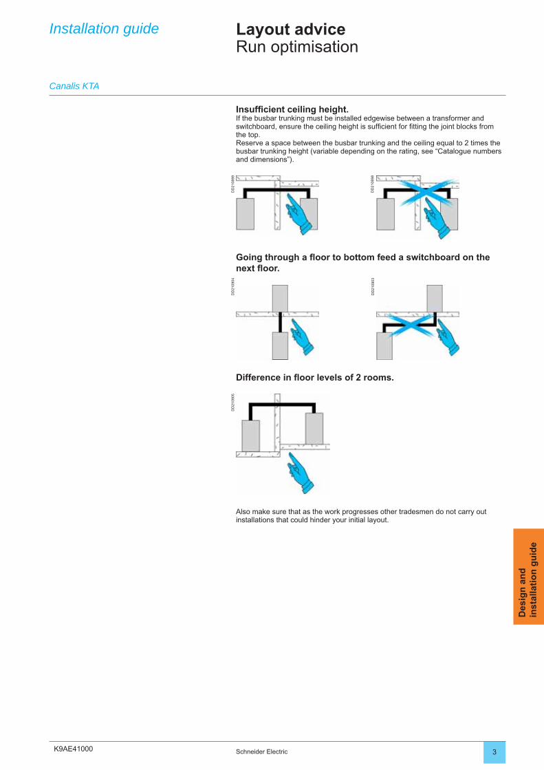
K9AE41000
DD
2108
99
DD
2108
98
DD
2109
04
DD
2109
03
DD
2109
05
3Schneider Electric
Des
ign
an
din
stal
lati
on
gu
ide
Insuffi cient ceiling height.If the busbar trunking must be installed edgewise between a transformer and switchboard, ensure the ceiling height is suffi cient for fi tting the joint blocks from the top.Reserve a space between the busbar trunking and the ceiling equal to 2 times the busbar trunking height (variable depending on the rating, see “Catalogue numbers and dimensions”).
Going through a fl oor to bottom feed a switchboard on the next fl oor.
Difference in fl oor levels of 2 rooms.
Also make sure that as the work progresses other tradesmen do not carry out installations that could hinder your initial layout.
Installation guide
Canalis KTA
Layout adviceRun optimisation
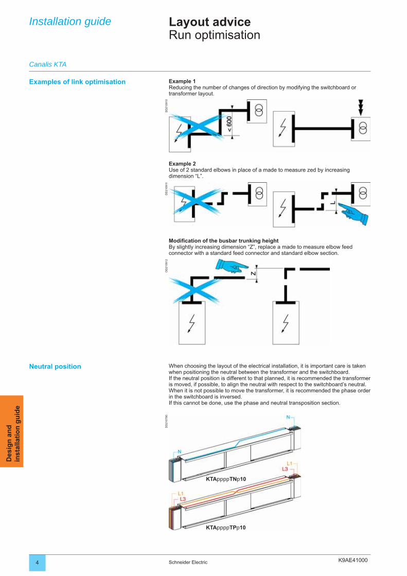
K9AE41000
KTAppppTNp10
KTAppppTPp10
DD
2109
10D
D21
0911
DD
2109
12D
D21
0780
4 Schneider Electric
Des
ign
an
din
stal
lati
on
gu
ideLayout adviceRun optimisation
Installation guide
Canalis KTA
Example 2Use of 2 standard elbows in place of a made to measure zed by increasing dimension “L”.
Example 1Reducing the number of changes of direction by modifying the switchboard or transformer layout.
Examples of link optimisation
Modifi cation of the busbar trunking heightBy slightly increasing dimension “Z”, replace a made to measure elbow feed connector with a standard feed connector and standard elbow section.
Neutral position When choosing the layout of the electrical installation, it is important care is taken when positioning the neutral between the transformer and the switchboard.If the neutral position is different to that planned, it is recommended the transformer is moved, if possible, to align the neutral with respect to the switchboard’s neutral.When it is not possible to move the transformer, it is recommended the phase order in the switchboard is inversed.If this cannot be done, use the phase and neutral transposition section.
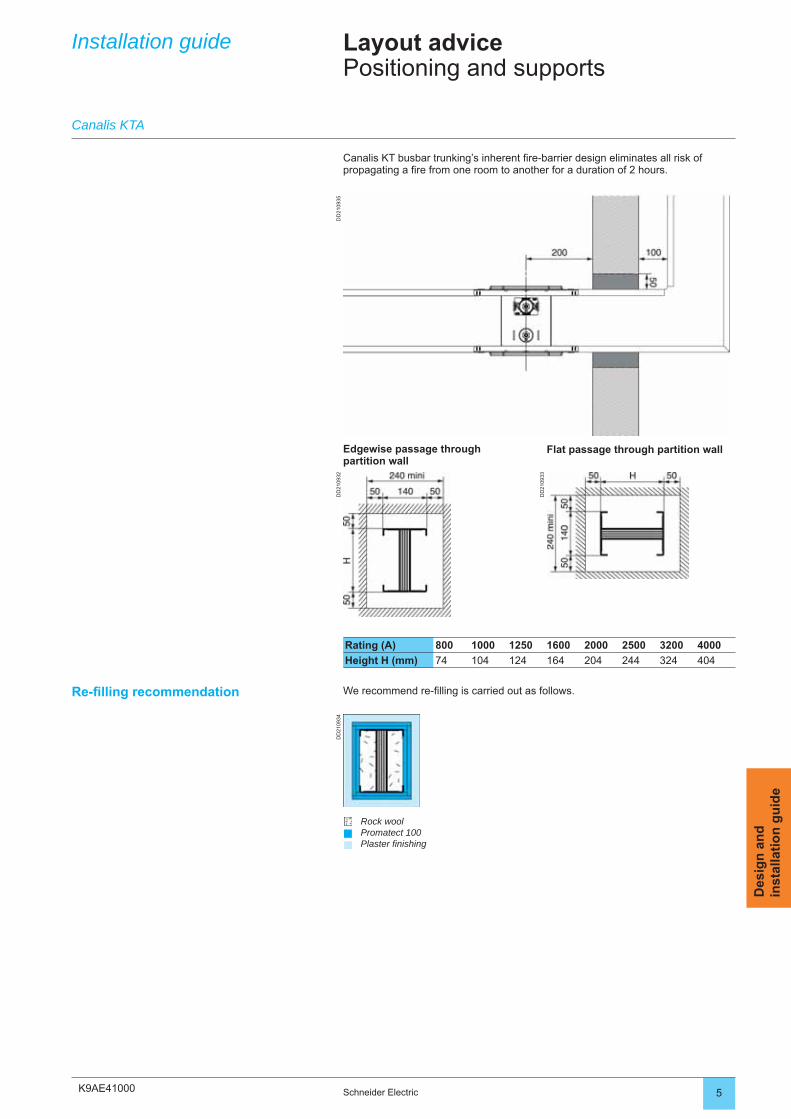
K9AE41000
DD
2109
35D
D21
0932
DD
2109
33
DD
2109
34
5Schneider Electric
Des
ign
an
din
stal
lati
on
gu
ide
Installation guide Layout advicePositioning and supports
Canalis KT busbar trunking’s inherent fi re-barrier design eliminates all risk of propagating a fi re from one room to another for a duration of 2 hours.
Canalis KTA
Rating (A) 800 1000 1250 1600 2000 2500 3200 4000
Height H (mm) 74 104 124 164 204 244 324 404
Edgewise passage through partition wall
Flat passage through partition wall
We recommend re-fi lling is carried out as follows.
Rock woolPromatect 100Plaster fi nishing
Re-fi lling recommendation
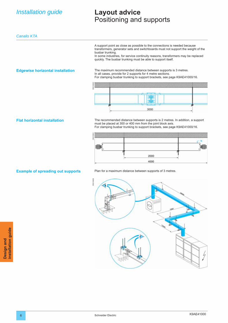
K9AE41000
DD
2109
30D
D21
0931
DD
2109
29
6 Schneider Electric
Des
ign
an
din
stal
lati
on
gu
ide
Installation guide Layout advicePositioning and supports
A support point as close as possible to the connections is needed because transformers, generator sets and switchboards must not support the weight of the busbar trunking.In some industries, for service continuity reasons, transformers may be replaced quickly. The busbar trunking must be able to support itself.
Flat horizontal installation
Canalis KTA
Example of spreading out supports
Edgewise horizontal installation The maximum recommended distance between supports is 3 metres.In all cases, provide for 2 supports for 4 metre sections.For clamping busbar trunking to support brackets, see page K9AE41000/16.
The recommended distance between supports is 2 metres. In addition, a support must be placed at 300 or 400 mm from the joint block axis.For clamping busbar trunking to support brackets, see page K9AE41000/16.
Plan for a maximum distance between supports of 3 metres.
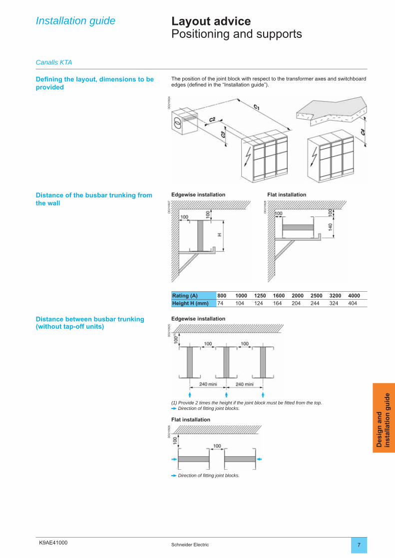
K9AE41000
DD
2109
24D
D21
0927
DD
2109
28
DD
2109
25D
D21
0926
7Schneider Electric
Des
ign
an
din
stal
lati
on
gu
ide
Installation guide Layout advicePositioning and supports
Defi ning the layout, dimensions to be provided
Distance of the busbar trunking from the wall
Rating (A) 800 1000 1250 1600 2000 2500 3200 4000
Height H (mm) 74 104 124 164 204 244 324 404
Distance between busbar trunking(without tap-off units)
Edgewise installation
Canalis KTA
The position of the joint block with respect to the transformer axes and switchboard edges (defi ned in the “Installation guide”).
Edgewise installation Flat installation
(1) Provide 2 times the height if the joint block must be fi tted from the top. Direction of fi tting joint blocks.
Flat installation
Direction of fi tting joint blocks.
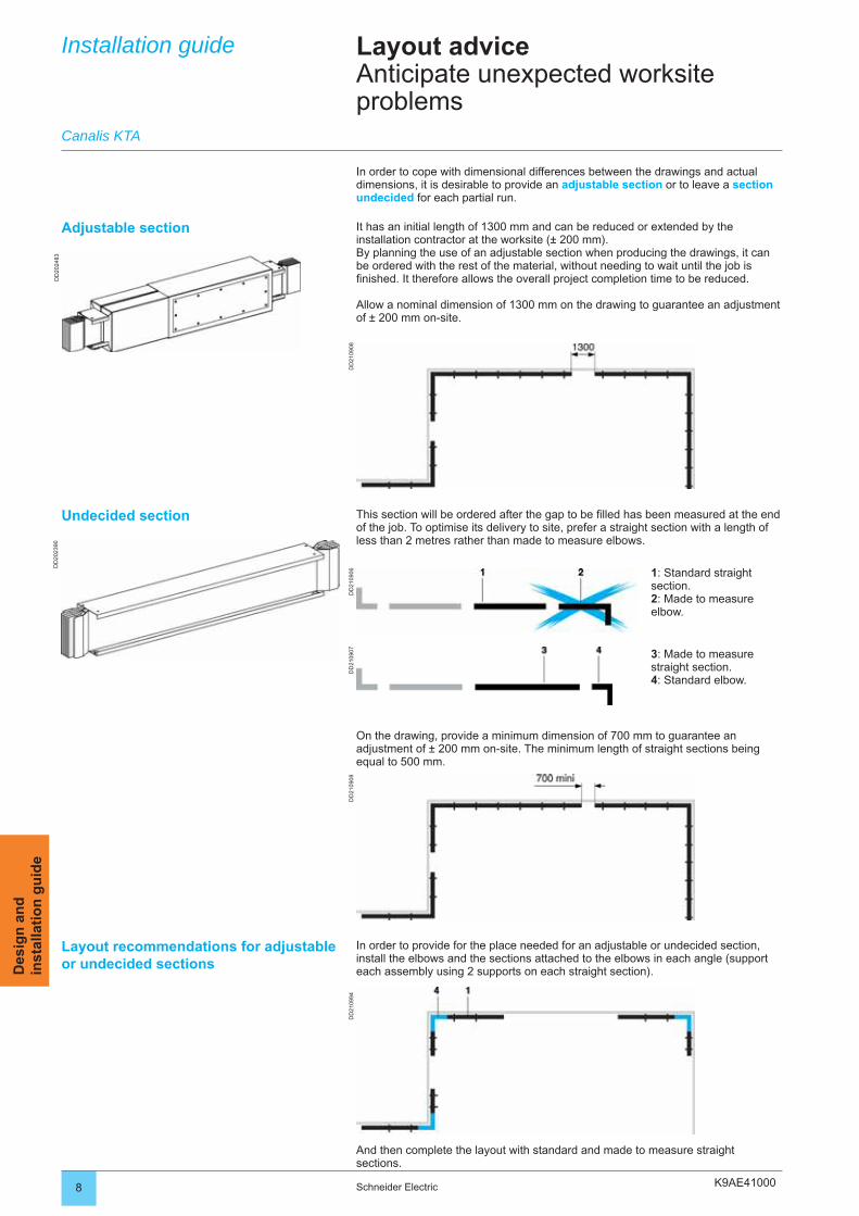
K9AE41000
DD
2024
83D
D20
2390
DD
2109
08D
D21
0906
DD
2109
07D
D21
0908
DD
2109
94
8 Schneider Electric
Des
ign
an
din
stal
lati
on
gu
ide
In order to cope with dimensional differences between the drawings and actual dimensions, it is desirable to provide an adjustable section or to leave a section undecided for each partial run.
1: Standard straight section.2: Made to measure elbow.
3: Made to measure straight section.4: Standard elbow.
Layout adviceAnticipate unexpected worksite problems
Installation guide
Canalis KTA
On the drawing, provide a minimum dimension of 700 mm to guarantee an adjustment of ± 200 mm on-site. The minimum length of straight sections being equal to 500 mm.
In order to provide for the place needed for an adjustable or undecided section, install the elbows and the sections attached to the elbows in each angle (support each assembly using 2 supports on each straight section).
This section will be ordered after the gap to be fi lled has been measured at the end of the job. To optimise its delivery to site, prefer a straight section with a length of less than 2 metres rather than made to measure elbows.
And then complete the layout with standard and made to measure straight sections.
Adjustable section It has an initial length of 1300 mm and can be reduced or extended by the installation contractor at the worksite (± 200 mm).By planning the use of an adjustable section when producing the drawings, it can be ordered with the rest of the material, without needing to wait until the job is fi nished. It therefore allows the overall project completion time to be reduced.
Allow a nominal dimension of 1300 mm on the drawing to guarantee an adjustment of ± 200 mm on-site.
Undecided section
Layout recommendations for adjustable or undecided sections
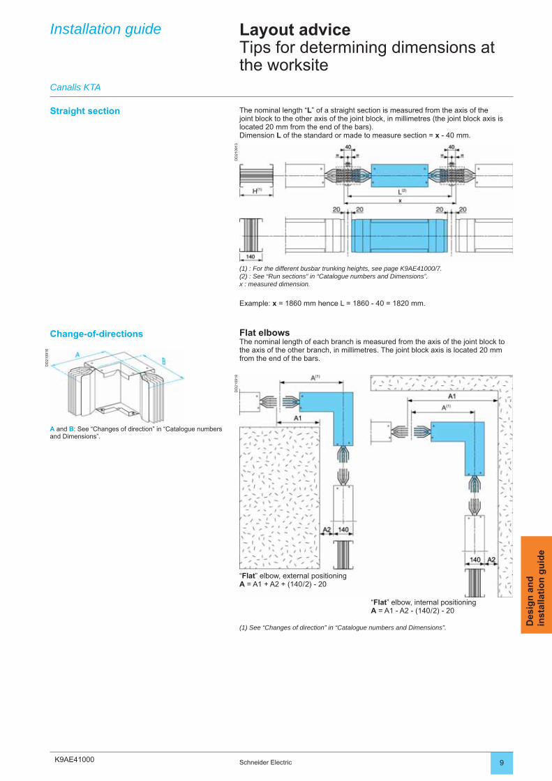
K9AE41000
DD
2109
13
DD
2109
16
DD
2109
18
9Schneider Electric
Des
ign
an
din
stal
lati
on
gu
ide
Installation guide Layout adviceTips for determining dimensions at the worksite
The nominal length “L” of a straight section is measured from the axis of the joint block to the other axis of the joint block, in millimetres (the joint block axis is located 20 mm from the end of the bars).Dimension L of the standard or made to measure section = x - 40 mm.
(1) : For the different busbar trunking heights, see page K9AE41000/7.(2) : See “Run sections” in “Catalogue numbers and Dimensions”.x : measured dimension.
Example: x = 1860 mm hence L = 1860 - 40 = 1820 mm.
Straight section
Canalis KTA
Flat elbowsThe nominal length of each branch is measured from the axis of the joint block to the axis of the other branch, in millimetres. The joint block axis is located 20 mm from the end of the bars.
“Flat” elbow, external positioningA = A1 + A2 + (140 / 2) - 20
“Flat” elbow, internal positioningA = A1 - A2 - (140 / 2) - 20
Change-of-directions
(1) See “Changes of direction” in “Catalogue numbers and Dimensions”.
A and B: See “Changes of direction” in “Catalogue numbers and Dimensions”.
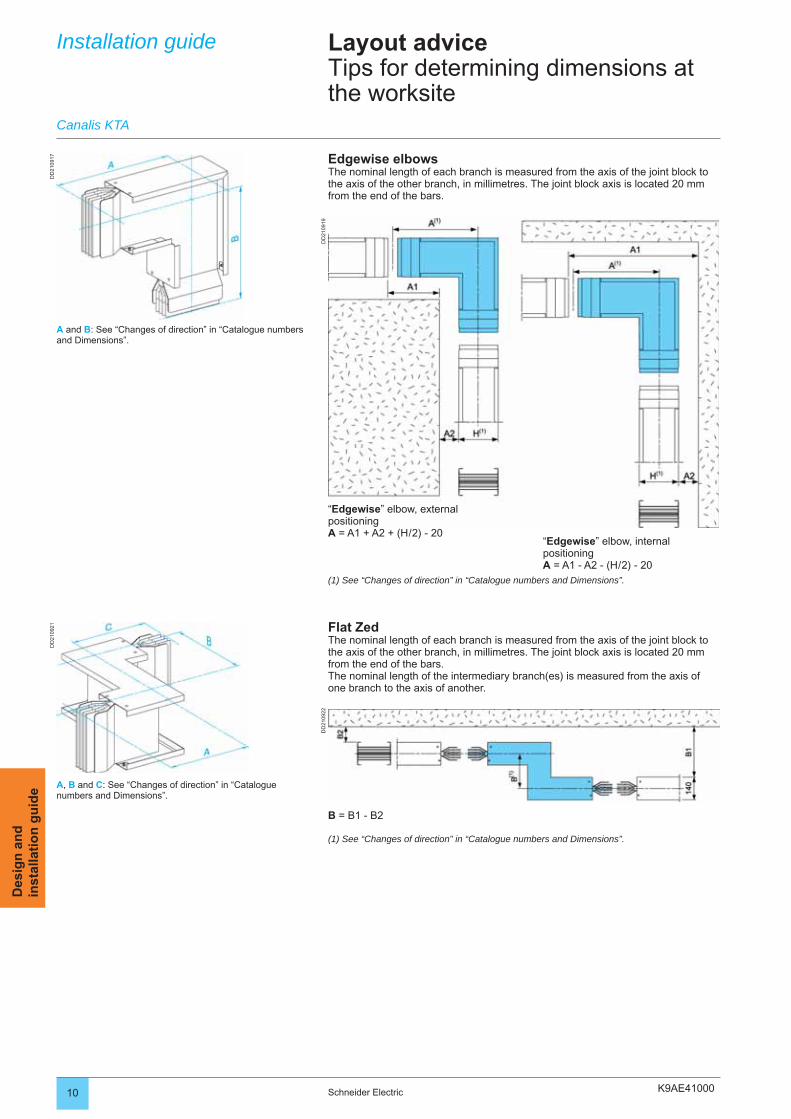
K9AE41000
DD
2109
17
DD
2109
19
DD
2109
21
DD
2109
22
10 Schneider Electric
Des
ign
an
din
stal
lati
on
gu
ide
Installation guide Layout adviceTips for determining dimensions at the worksite
“Edgewise” elbow, external positioningA = A1 + A2 + (H / 2) - 20
“Edgewise” elbow, internal positioningA = A1 - A2 - (H / 2) - 20
Canalis KTA
(1) See “Changes of direction” in “Catalogue numbers and Dimensions”.
A and B: See “Changes of direction” in “Catalogue numbers and Dimensions”.
Edgewise elbowsThe nominal length of each branch is measured from the axis of the joint block to the axis of the other branch, in millimetres. The joint block axis is located 20 mm from the end of the bars.
Flat ZedThe nominal length of each branch is measured from the axis of the joint block to the axis of the other branch, in millimetres. The joint block axis is located 20 mm from the end of the bars.The nominal length of the intermediary branch(es) is measured from the axis of one branch to the axis of another.
B = B1 - B2
(1) See “Changes of direction” in “Catalogue numbers and Dimensions”.
A, B and C: See “Changes of direction” in “Catalogue numbers and Dimensions”.
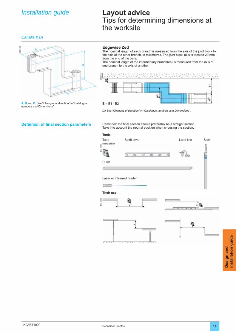
K9AE41000
DD
2109
20
DD
2109
23D
D21
0914
DD
2109
15
11Schneider Electric
Des
ign
an
din
stal
lati
on
gu
ide
Stick
Reminder: the fi nal section should preferably be a straight section. Take into account the neutral position when choosing the section.
Tools
Tape measure
Spirit level Lead line
Ruler
Laser or infra-red reader
Their use
Defi nition of fi nal section parameters
Installation guide Layout adviceTips for determining dimensions at the worksite
Edgewise ZedThe nominal length of each branch is measured from the axis of the joint block to the axis of the other branch, in millimetres. The joint block axis is located 20 mm from the end of the bars.The nominal length of the intermediary branch(es) is measured from the axis of one branch to the axis of another.
Canalis KTA
B = B1 - B2
(1) See “Changes of direction” in “Catalogue numbers and Dimensions”.
A, B and C: See “Changes of direction” in “Catalogue numbers and Dimensions”.
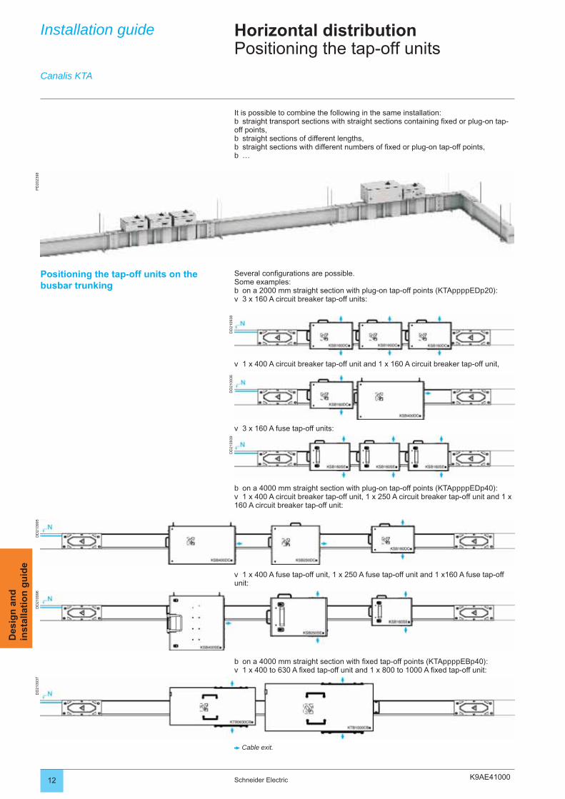
K9AE41000
PD
2023
98
DD
2109
38D
D21
0936
DD
2109
39
DD
2109
37D
D21
0995
DD
2109
96
12 Schneider Electric
Des
ign
an
din
stal
lati
on
gu
ide
Installation guide Horizontal distributionPositioning the tap-off units
It is possible to combine the following in the same installation:straight transport sections with straight sections containing fi xed or plug-on tap-
off points,straight sections of different lengths,straight sections with different numbers of fi xed or plug-on tap-off points,…
b
bbb
Canalis KTA
Positioning the tap-off units on the busbar trunking
Several confi gurations are possible.Some examples:
on a 2000 mm straight section with plug-on tap-off points (KTAppppEDp20):3 x 160 A circuit breaker tap-off units:
bv
1 x 400 A circuit breaker tap-off unit and 1 x 160 A circuit breaker tap-off unit,v
3 x 160 A fuse tap-off units:v
on a 4000 mm straight section with fi xed tap-off points (KTAppppEBp40):1 x 400 to 630 A fi xed tap-off unit and 1 x 800 to 1000 A fi xed tap-off unit:
bv
Cable exit.
on a 4000 mm straight section with plug-on tap-off points (KTAppppEDp40):1 x 400 A circuit breaker tap-off unit, 1 x 250 A circuit breaker tap-off unit and 1 x
160 A circuit breaker tap-off unit:
bv
1 x 400 A fuse tap-off unit, 1 x 250 A fuse tap-off unit and 1 x160 A fuse tap-off unit:v
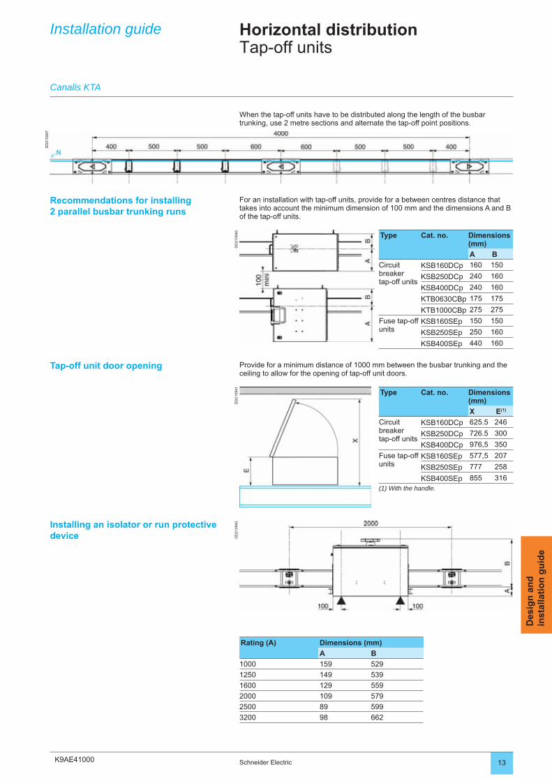
K9AE41000
DD
2109
40D
D21
0942
DD
2109
41
DD
2109
97
13Schneider Electric
Des
ign
an
din
stal
lati
on
gu
ide
Recommendations for installing 2 parallel busbar trunking runs
For an installation with tap-off units, provide for a between centres distance that takes into account the minimum dimension of 100 mm and the dimensions A and B of the tap-off units.
Tap-off unit door opening Provide for a minimum distance of 1000 mm between the busbar trunking and the ceiling to allow for the opening of tap-off unit doors.
Installing an isolator or run protective device
Rating (A) Dimensions (mm)
A B
1000 159 529
1250 149 539
1600 129 559
2000 109 579
2500 89 599
3200 98 662
When the tap-off units have to be distributed along the length of the busbar trunking, use 2 metre sections and alternate the tap-off point positions.
Type Cat. no. Dimensions (mm)
A B
Circuit breaker tap-off units
KSB160DCp 160 150
KSB250DCp 240 160
KSB400DCp 240 160
KTB0630CBp 175 175
KTB1000CBp 275 275
Fuse tap-off units
KSB160SEp 150 150
KSB250SEp 250 160
KSB400SEp 440 160
Type Cat. no. Dimensions (mm)
X E(1)
Circuit breaker tap-off units
KSB160DCp 625.5 246
KSB250DCp 726.5 300
KSB400DCp 976,5 350
Fuse tap-off units
KSB160SEp 577,5 207
KSB250SEp 777 258
KSB400SEp 855 316(1) With the handle.
Installation guide
Canalis KTA
Horizontal distributionTap-off units
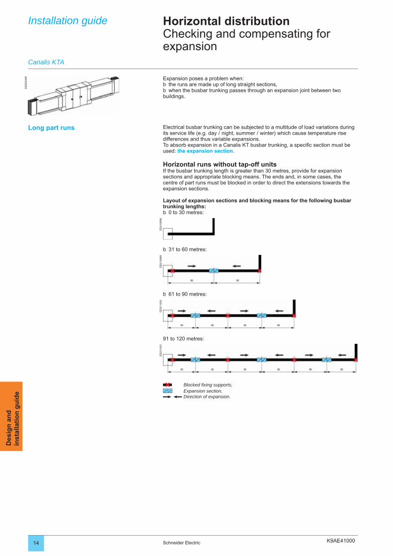
K9AE41000
DD
2024
46
DD
2109
98D
D21
0999
DD
2110
00D
D21
1001
14 Schneider Electric
Des
ign
an
din
stal
lati
on
gu
ide
Expansion poses a problem when:the runs are made up of long straight sections,when the busbar trunking passes through an expansion joint between two
buildings.
bb
Installation guide
Canalis KTA
Horizontal distributionChecking and compensating for expansion
31 to 60 metres:b
61 to 90 metres:b
91 to 120 metres:
Blocked fi xing supports,Expansion section,Direction of expansion.
Electrical busbar trunking can be subjected to a multitude of load variations during its service life (e.g. day / night, summer / winter) which cause temperature rise differences and thus variable expansions.To absorb expansion in a Canalis KT busbar trunking, a specifi c section must be used: the expansion section.
Horizontal runs without tap-off unitsIf the busbar trunking length is greater than 30 metres, provide for expansion sections and appropriate blocking means. The ends and, in some cases, the centre of part runs must be blocked in order to direct the extensions towards the expansion sections.
Layout of expansion sections and blocking means for the following busbar trunking lengths:
0 to 30 metres:b
Long part runs
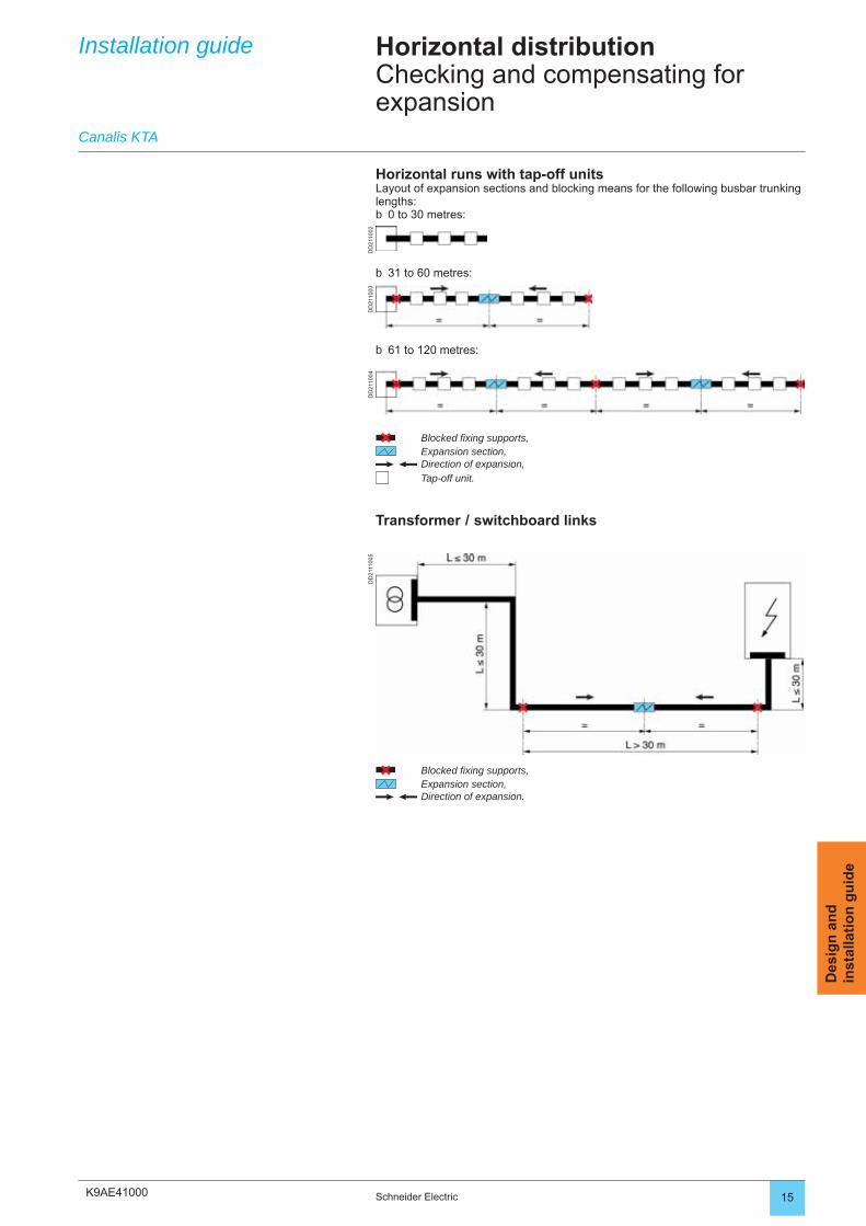
K9AE41000
DD
2110
02D
D21
1003
DD
2110
04D
D21
1100
5
15Schneider Electric
Des
ign
an
din
stal
lati
on
gu
ide
31 to 60 metres:b
61 to 120 metres:b
Blocked fi xing supports,Expansion section,Direction of expansion,Tap-off unit.
Transformer / switchboard links
Horizontal runs with tap-off unitsLayout of expansion sections and blocking means for the following busbar trunking lengths:
0 to 30 metres:b
Installation guide
Canalis KTA
Horizontal distributionChecking and compensating for expansion
Blocked fi xing supports,Expansion section,Direction of expansion.
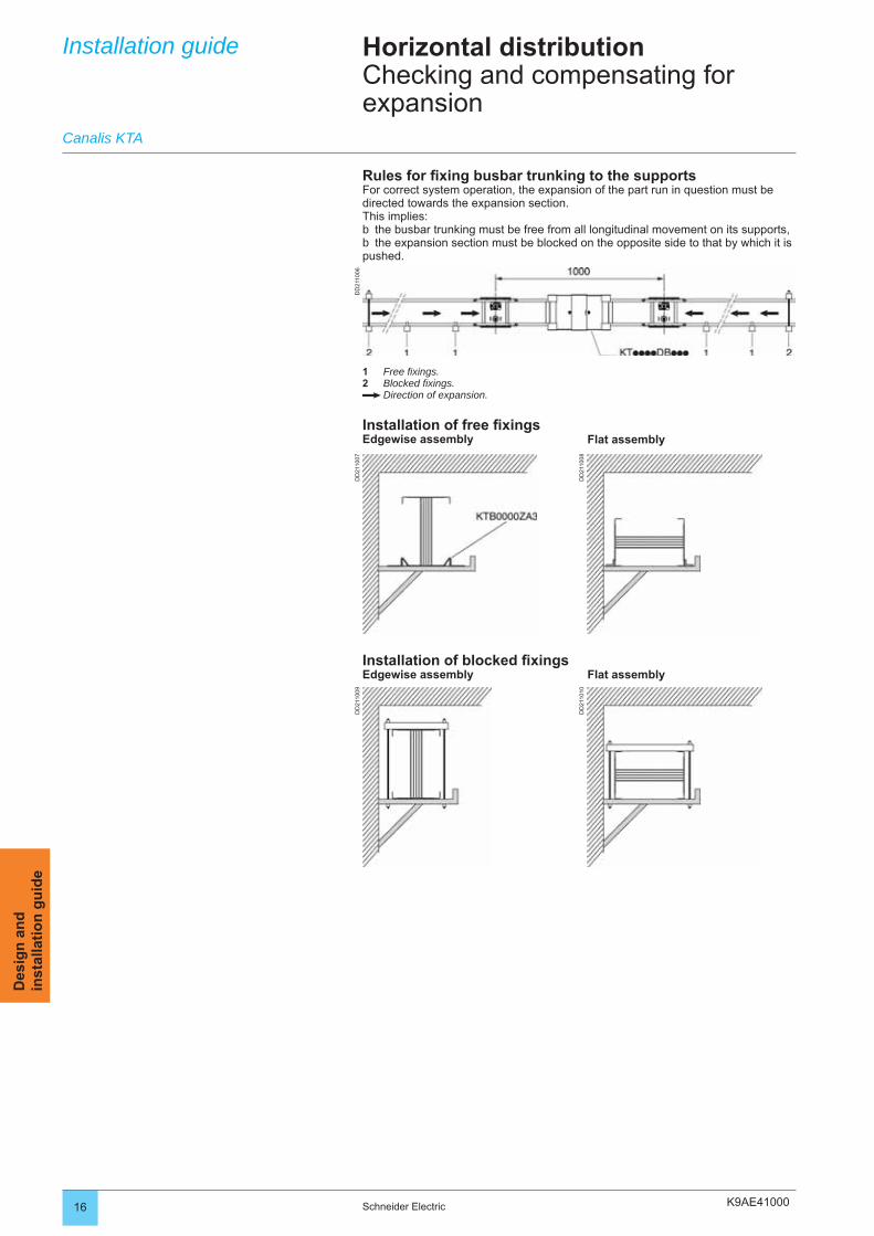
K9AE41000
DD
2110
07
DD
2110
08
DD
2110
09
DD
2110
10
DD
2110
06
16 Schneider Electric
Des
ign
an
din
stal
lati
on
gu
ide
Installation guide
Canalis KTA
Horizontal distributionChecking and compensating for expansion
Rules for fi xing busbar trunking to the supportsFor correct system operation, the expansion of the part run in question must be directed towards the expansion section.This implies:
the busbar trunking must be free from all longitudinal movement on its supports,the expansion section must be blocked on the opposite side to that by which it is
pushed.
bb
1 Free fi xings.2 Blocked fi xings.
Direction of expansion.
Installation of free fi xingsEdgewise assembly Flat assembly
Installation of blocked fi xingsEdgewise assembly Flat assembly
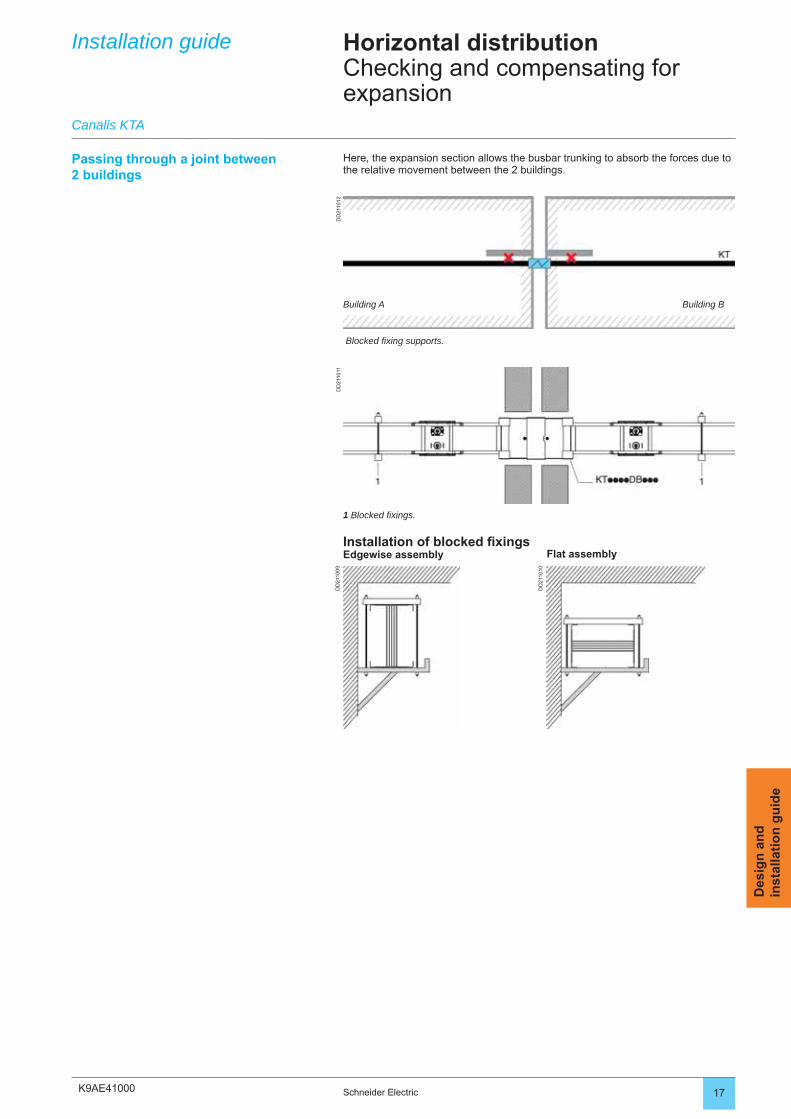
K9AE41000
DD
2110
09
DD
2110
10
DD
2110
11D
D21
1012
17Schneider Electric
Des
ign
an
din
stal
lati
on
gu
ide
Installation guide
Canalis KTA
Horizontal distributionChecking and compensating for expansion
Passing through a joint between 2 buildings
Here, the expansion section allows the busbar trunking to absorb the forces due to the relative movement between the 2 buildings.
1 Blocked fi xings.
Installation of blocked fi xingsEdgewise assembly Flat assembly
Building A Building B
Blocked fi xing supports.
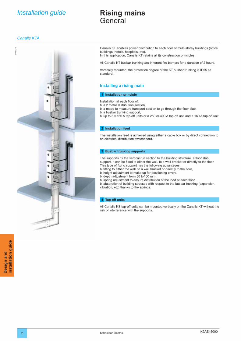
K9AE45000
PD
2023
19
2 Schneider Electric
Des
ign
an
din
stal
lati
on
gu
ide
Installation guide Rising mainsGeneral
Canalis KT enables power distribution to each fl oor of multi-storey buildings (offi ce buildings, hotels, hospitals, etc).In this application, Canalis KT retains all its construction principles:
All Canalis KT busbar trunking are inherent fi re barriers for a duration of 2 hours.
Vertically mounted, the protection degree of the KT busbar trunking is IP55 as standard.
Installing a rising main
1 Installation principle
Installation at each fl oor of:a 2 metre distribution section,a made to measure transport section to go through the fl oor slab,a busbar trunking support,up to 3 x 160 A tap-off units or a 250 or 400 A tap-off unit and a 160 A tap-off unit.
2 Installation feed
The installation feed is achieved using either a cable box or by direct connection to an electrical distribution switchboard.
3 Busbar trunking supports
The supports fi x the vertical run section to the building structure. a fl oor slab support. It can be fi xed to either the wall, to a wall bracket or directly to the fl oor,This type of fi xing support has the following advantages:fi tting to either the wall, to a wall bracket or directly to the fl oor,height adjustment to make up for positioning errors,depth adjustment from 50 to100 mm,spring adjustment to ensure distribution of the load at each fl oor,absorption of building stresses with respect to the busbar trunking (expansion,
vibration, etc) thanks to the springs.
4 Tap-off units
All Canalis KS tap-off units can be mounted vertically on the Canalis KT without the risk of interference with the supports.
bbbb
bbbbb
Canalis KTA
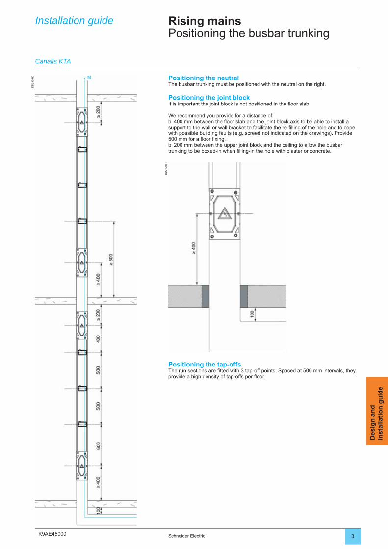
K9AE45000
DD
2109
60
DD
2109
61
3Schneider Electric
Des
ign
an
din
stal
lati
on
gu
ide
Rising mainsPositioning the busbar trunking
Installation guide
Positioning the neutralThe busbar trunking must be positioned with the neutral on the right.
Positioning the joint blockIt is important the joint block is not positioned in the fl oor slab.
We recommend you provide for a distance of: 400 mm between the fl oor slab and the joint block axis to be able to install a
support to the wall or wall bracket to facilitate the re-fi lling of the hole and to cope with possible building faults (e.g. screed not indicated on the drawings). Provide 500 mm for a fl oor fi xing.
200 mm between the upper joint block and the ceiling to allow the busbar trunking to be boxed-in when fi lling-in the hole with plaster or concrete.
b
b
Positioning the tap-offsThe run sections are fi tted with 3 tap-off points. Spaced at 500 mm intervals, they provide a high density of tap-offs per fl oor.
Canalis KTA
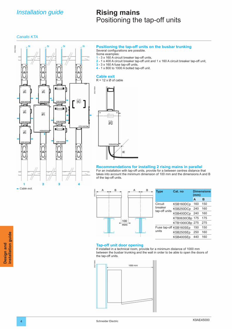
K9AE45000
DD
2109
62
DD
2109
64D
D21
0954
DD
2109
63
4 Schneider Electric
Des
ign
an
din
stal
lati
on
gu
ide
Installation guide Rising mainsPositioning the tap-off units
Positioning the tap-off units on the busbar trunkingSeveral confi gurations are possible.Some examples:1 - 3 x 160 A circuit breaker tap-off units,2 - 1 x 400 A circuit breaker tap-off unit and 1 x 160 A circuit breaker tap-off unit,3 - 3 x 160 A fuse tap-off units,4 - 1 x 800 to 1000 A bolted tap-off unit.
Cable exitR = 12 x Ø of cable
Canalis KTA
Tap-off unit door openingIf installed in a technical room, provide for a minimum distance of 1000 mm between the busbar trunking and the wall in order to be able to open the doors of the tap-off units.
Recommendations for installing 2 rising mains in parallelFor an installation with tap-off units, provide for a between centres distance that takes into account the minimum dimension of 100 mm and the dimensions A and B of the tap-off units.
Cable exit.Type Cat. no Dimensions
(mm)
A B
Circuit breaker tap-off units
KSB160DCp 160 150
KSB250DCp 240 160
KSB400DCp 240 160
KTB0630CBp 175 175
KTB1000CBp 275 275
Fuse tap-off units
KSB160SEp 150 150
KSB250SEp 250 160
KSB400SEp 440 160
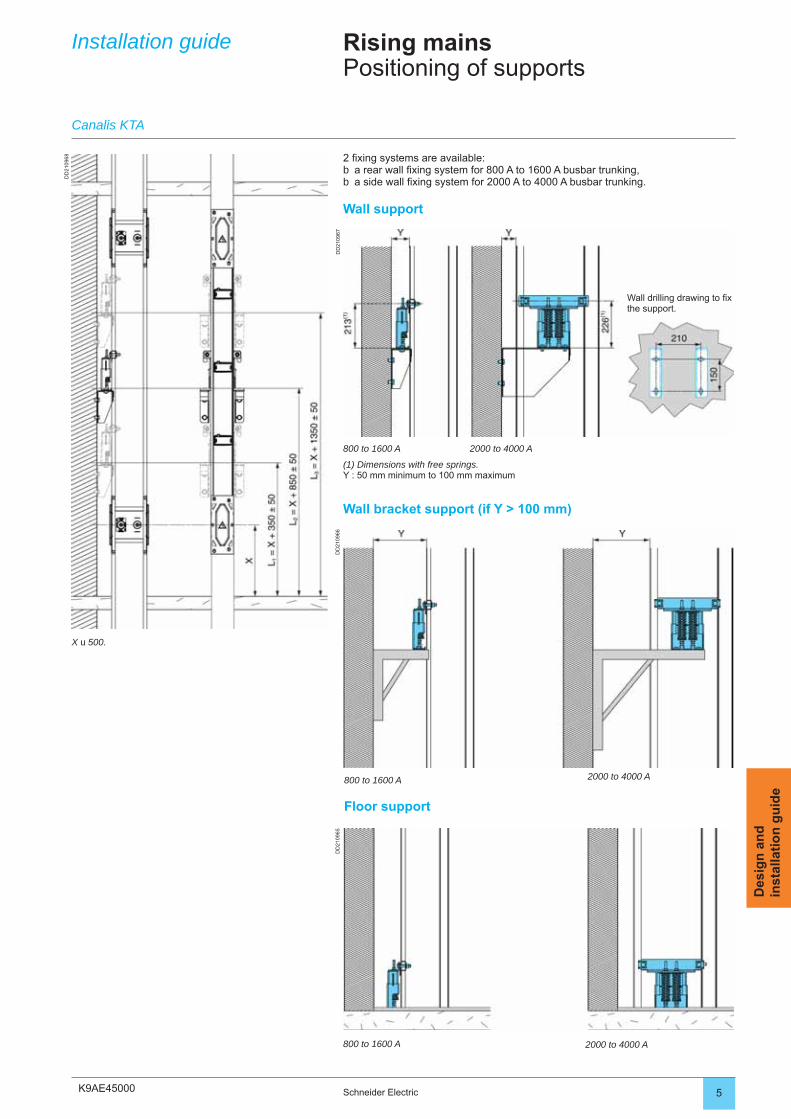
K9AE45000
DD
2109
68
DD
2109
67D
D21
0966
DD
2109
65
5Schneider Electric
Des
ign
an
din
stal
lati
on
gu
ide
Installation guide Rising mainsPositioning of supports
2 fi xing systems are available:a rear wall fi xing system for 800 A to 1600 A busbar trunking,a side wall fi xing system for 2000 A to 4000 A busbar trunking.
Wall support
bb
Canalis KTA
X u 500.
800 to 1600 A
(1) Dimensions with free springs.Y : 50 mm minimum to 100 mm maximum
800 to 1600 A
2000 to 4000 A
Wall bracket support (if Y > 100 mm)
2000 to 4000 A
Floor support
800 to 1600 A 2000 to 4000 A
Wall drilling drawing to fi x the support.
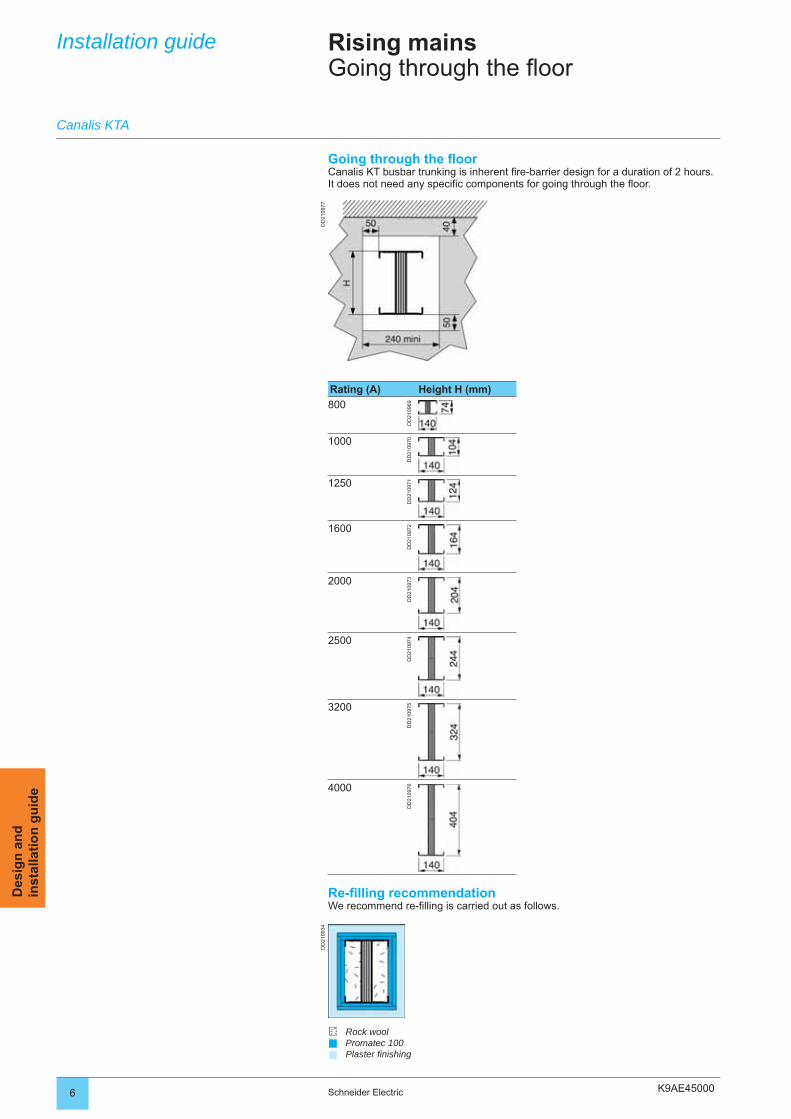
K9AE45000
DD
2109
77D
D21
0934
6 Schneider Electric
Des
ign
an
din
stal
lati
on
gu
ide
Installation guide Rising mainsGoing through the floor
Going through the fl oorCanalis KT busbar trunking is inherent fi re-barrier design for a duration of 2 hours. It does not need any specifi c components for going through the fl oor.
Canalis KTA
Rating (A) Height H (mm)
800D
D21
0969
1000
DD
2109
70
1250
DD
2109
71
1600
DD
2109
72
2000
DD
2109
73
2500
DD
2109
74
3200
DD
2109
75
4000
DD
2109
76
Re-fi lling recommendationWe recommend re-fi lling is carried out as follows.
Rock woolPromatec 100Plaster fi nishing
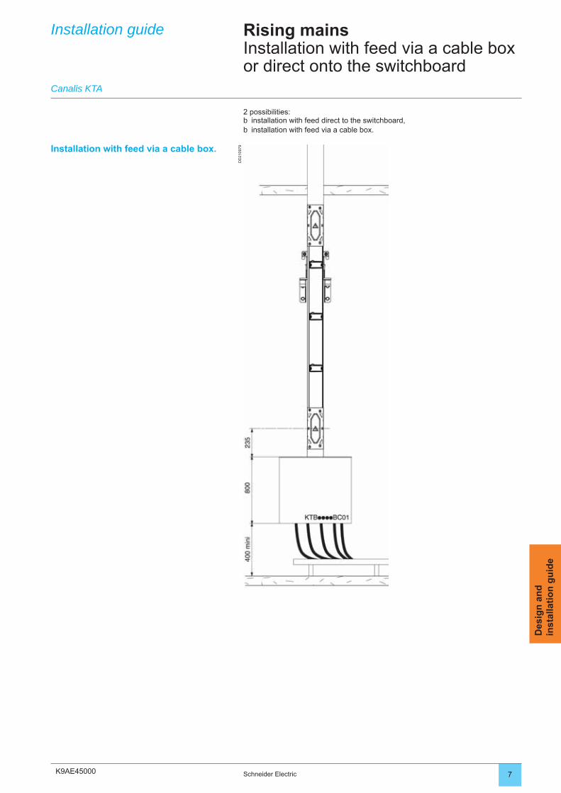
K9AE45000
DD
2109
79
7Schneider Electric
Des
ign
an
din
stal
lati
on
gu
ide
Installation guide Rising mainsInstallation with feed via a cable box or direct onto the switchboard
Canalis KTA
2 possibilities:installation with feed direct to the switchboard,installation with feed via a cable box.
bb
Installation with feed via a cable box.
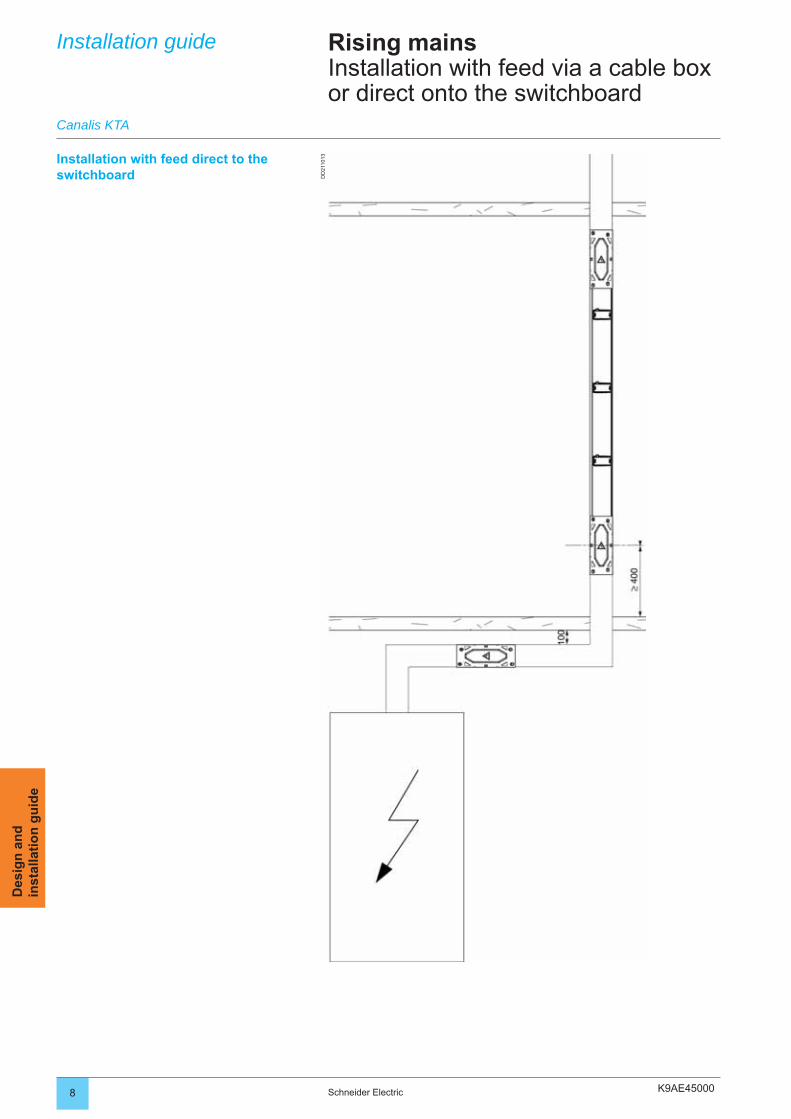
K9AE45000
DD
2110
13
8 Schneider Electric
Des
ign
an
din
stal
lati
on
gu
ide
Installation guide
Canalis KTA
Rising mainsInstallation with feed via a cable box or direct onto the switchboard
Installation with feed direct to the switchboard

K9AE45000 9Schneider Electric
Des
ign
an
din
stal
lati
on
gu
ide
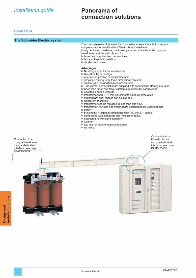
K9AE42000
PD
2024
32
2 Schneider Electric
Des
ign
an
din
stal
lati
on
gu
ide
Installation guide Panorama ofconnection solutions
The Schneider Electric systemThe comprehensive Schneider Electric system makes it simple to design a complete transformer / Canalis KT / switchboard installation.Using dedicated interfaces, the trunking connects directly to the dry-type transformer and the switchboard for:
tested and standardised connections,fast and fl exible installation,shorter lead times.
AdvantagesNo design work for the connections.Simplifi ed layout design:pre-defi ned position of the jointing unit,simplifi ed routing (only three dimensions required),smaller size (no additional covers required).Transformer and switchboard supplied with connections already mounted.Short lead times and fewer catalogue numbers for connections.Adaptable on the worksite:transformer end: ± 15 mm adjustments along all three axes,switchboard end: phases can be inverted.Continuity of service:transformer can be replaced in less than one hour,transformer, trunking and switchboard designed to be used together.Safety:trunking fully tested in compliance with IEC 60439-1 and 2,compliance with standards and installation rules,excellent fi re-withstand capability.Comfort:low level of electromagnetic radiation,no noise.
bbb
bbvvvbbbvvbvvbvvvbvv
Canalis KTA
Connection to a dry-type transformer using a dedicated interface, see page K9AE43000/4.
Connection to an LV switchboard using a dedicated interface, see page K9AE42000/6.
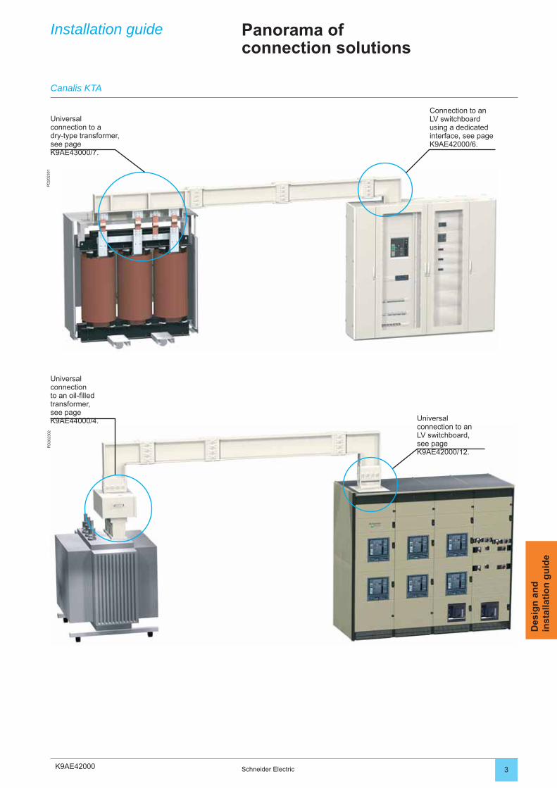
K9AE42000
PD
2023
01P
D20
2302
3Schneider Electric
Des
ign
an
din
stal
lati
on
gu
ide
Universal connection to a dry-type transformer, see page K9AE43000/7.
Connection to an LV switchboard using a dedicated interface, see page K9AE42000/6.
Universal connection to an oil-fi lled transformer, see page K9AE44000/4. Universal
connection to an LV switchboard, see page K9AE42000/12.
Installation guide Panorama ofconnection solutions
Canalis KTA
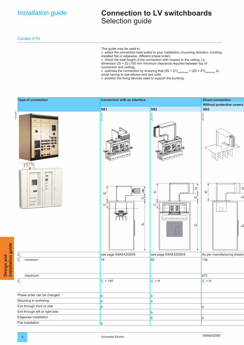
K9AE420004 Schneider Electric
Des
ign
an
din
stal
lati
on
gu
ide
Installation guide Connection to LV switchboardsSelection guide
Type of connection Connection with an interface Direct connection
Without protective covers
SB1 SB2 SB3
PD
2023
04
DD
21v0
753
DD
2107
54
DD
2107
55
Z0
see page K9AE42000/6 see page K9AE42000/6 As per manufacturing drawing
Z1 minimum 74 82 138
maximum - - 472
Z2
Z1 + 140 Z
1 + H Z
1 + H
Phase order can be changed b bMounting in workshop b bExit through front or rear b bExit through left or right side bEdgewise installation b bFlat installation b
Canalis KTA
This guide may be used to:select the connection best suited to your installation (incoming direction, trunking
installed fl at or edgewise, different phase order),check the total height of the connection with respect to the ceiling, i.e.
dimension Z0 + Z2 (100 mm minimum clearance required between top of connection and ceiling),
optimise the connection by ensuring that (Z0 + Z1)switchboard
= (Z0 + Z1)transformer
to avoid having to use elbows and zed units,
position the fi xing devices used to support the trunking.
v
v
v
v
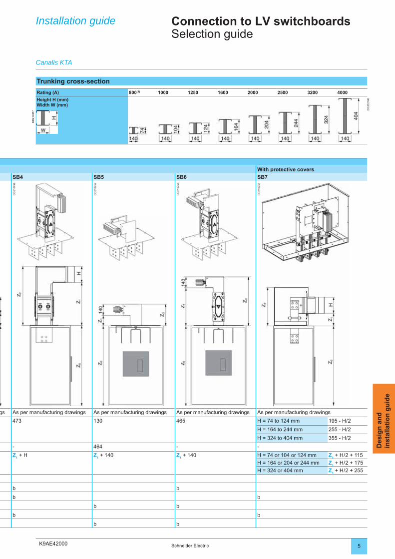
K9AE42000 5Schneider Electric
Des
ign
an
din
stal
lati
on
gu
ide
With protective covers
SB4 SB5 SB6 SB7
DD
2107
56
DD
2107
57
DD
2107
58
DD
2107
59
gs As per manufacturing drawings As per manufacturing drawings As per manufacturing drawings As per manufacturing drawings
473 130 465 H = 74 to 124 mm 195 - H / 2
H = 164 to 244 mm 255 - H / 2
H = 324 to 404 mm 355 - H / 2
- 464 - -
Z1 + H Z
1 + 140 Z
1 + 140 H = 74 or 104 or 124 mm Z
1 + H / 2 + 115
H = 164 or 204 or 244 mm Z1 + H / 2 + 175
H = 324 or 404 mm Z1 + H / 2 + 255
b b
b b
b b
b b
b b
Installation guide Connection to LV switchboardsSelection guide
Canalis KTA
Trunking cross-section
Rating (A) 800(1) 1000 1250 1600 2000 2500 3200 4000
Height H (mm)Width W (mm)
DD
2021
80
DD
2108
67
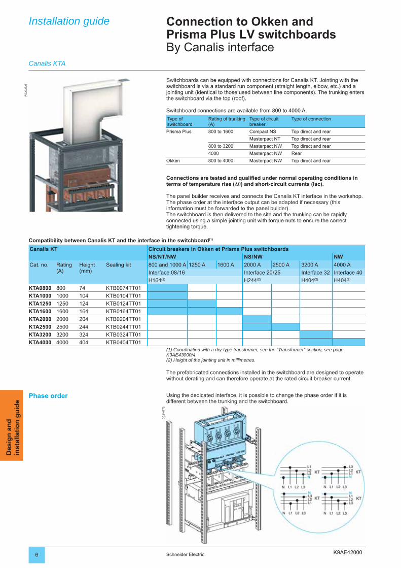
K9AE42000
PD
2023
28
DD
2107
72
6 Schneider Electric
Des
ign
an
din
stal
lati
on
gu
ide
Installation guide Connection to Okken andPrisma Plus LV switchboardsBy Canalis interface
Switchboards can be equipped with connections for Canalis KT. Jointing with the switchboard is via a standard run component (straight length, elbow, etc.) and a jointing unit (identical to those used between line components). The trunking enters the switchboard via the top (roof).
Switchboard connections are available from 800 to 4000 A.
Type of switchboard
Rating of trunking (A)
Type of circuit breaker
Type of connection
Prisma Plus 800 to 1600 Compact NS Top direct and rear
Masterpact NT Top direct and rear
800 to 3200 Masterpact NW Top direct and rear
4000 Masterpact NW Rear
Okken 800 to 4000 Masterpact NW Top direct and rear
Connections are tested and qualifi ed under normal operating conditions in terms of temperature rise (Δθ) and short-circuit currents (Isc).
The panel builder receives and connects the Canalis KT interface in the workshop. The phase order at the interface output can be adapted if necessary (this information must be forwarded to the panel builder).The switchboard is then delivered to the site and the trunking can be rapidly connected using a simple jointing unit with torque nuts to ensure the correct tightening torque.
Compatibility between Canalis KT and the interface in the switchboard(1)
Canalis KT Circuit breakers in Okken et Prisma Plus switchboards
NS / NT / NW NS / NW NW
Cat. no. Rating (A)
Height (mm)
Sealing kit 800 and 1000 A 1250 A 1600 A 2000 A 2500 A 3200 A 4000 A
Interface 08 / 16 Interface 20 / 25 Interface 32 Interface 40
H164(2) H244(2) H404(2) H404(2)
KTA0800 800 74 KTB0074TT01
KTA1000 1000 104 KTB0104TT01
KTA1250 1250 124 KTB0124TT01
KTA1600 1600 164 KTB0164TT01
KTA2000 2000 204 KTB0204TT01
KTA2500 2500 244 KTB0244TT01
KTA3200 3200 324 KTB0324TT01
KTA4000 4000 404 KTB0404TT01(1) Coordination with a dry-type transformer, see the “Transformer” section, see page K9AE43000/4.(2) Height of the jointing unit in millimetres.
The prefabricated connections installed in the switchboard are designed to operate without derating and can therefore operate at the rated circuit breaker current.
Canalis KTA
Phase order Using the dedicated interface, it is possible to change the phase order if it is different between the trunking and the switchboard.
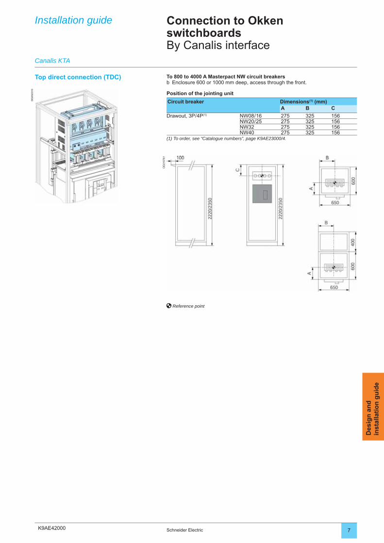
K9AE42000
DD
2023
10
DD
2107
61
7Schneider Electric
Des
ign
an
din
stal
lati
on
gu
ide
Installation guide Connection to Okken switchboardsBy Canalis interface
To 800 to 4000 A Masterpact NW circuit breakersEnclosure 600 or 1000 mm deep, access through the front.
Position of the jointing unit
Circuit breaker Dimensions(1) (mm)A B C
Drawout, 3P / 4P(1) NW08 / 16 275 325 156NW20 / 25 275 325 156NW32 275 325 156NW40 275 325 156
(1) To order, see “Catalogue numbers”, page K9AE23000/4.
b
Reference point
Top direct connection (TDC)
Canalis KTA
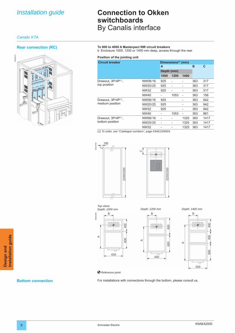
K9AE42000
DD
2023
11
DD
2107
63D
D20
2384
8 Schneider Electric
Des
ign
an
din
stal
lati
on
gu
ide
Rear connection (RC) To 800 to 4000 A Masterpact NW circuit breakersEnclosure 1000, 1200 or 1400 mm deep, access through the rear.
Position of the jointing unit
Circuit breaker Dimensions(1) (mm)A B C
Depth (mm)
1000 1200 1400
Drawout, 3P / 4P(1) ,top position
NW08 / 16 925 - - 363 317
NW20 / 25 925 - - 363 317
NW32 925 - - 363 317
NW40 - 1053 - 363 156
Drawout, 3P / 4P(1) ,medium position
NW08 / 16 925 - 363 942
NW20 / 25 925 - 363 942
NW32 925 - 363 942
NW40 - 1053 - 363 881
Drawout, 3P / 4P(1) ,bottom position
NW08 / 16 - - 1325 363 1417
NW20 / 25 - - 1325 363 1417
NW32 - - 1325 363 1417(1) To order, see “Catalogue numbers”, page K9AE23000/4.
b
Reference point
Installation guide Connection to Okken switchboardsBy Canalis interface
Bottom connection For installations with connections through the bottom, please consult us.
Canalis KTA
Top viewsDepth: 1000 mm Depth: 1200 mm Depth: 1400 mm
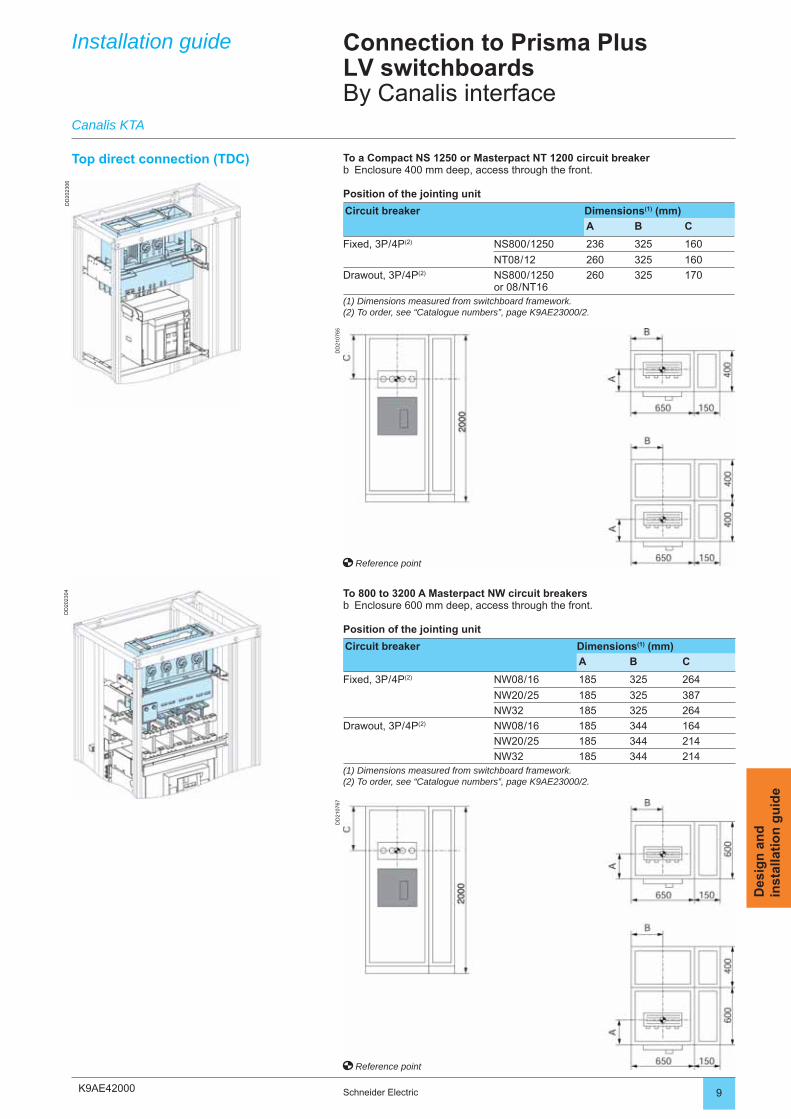
K9AE42000
DD
2023
06
DD
2107
65
DD
2023
04
DD
2107
67
9Schneider Electric
Des
ign
an
din
stal
lati
on
gu
ide
Installation guide Connection to Prisma PlusLV switchboardsBy Canalis interface
To a Compact NS 1250 or Masterpact NT 1200 circuit breakerEnclosure 400 mm deep, access through the front.
Position of the jointing unit
Circuit breaker Dimensions(1) (mm)
A B C
Fixed, 3P / 4P(2) NS800 / 1250 236 325 160
NT08 / 12 260 325 160
Drawout, 3P / 4P(2) NS800 / 1250 or 08 / NT16
260 325 170
(1) Dimensions measured from switchboard framework.(2) To order, see “Catalogue numbers”, page K9AE23000/2.
b
To 800 to 3200 A Masterpact NW circuit breakersEnclosure 600 mm deep, access through the front.
Position of the jointing unit
Circuit breaker Dimensions(1) (mm)
A B C
Fixed, 3P / 4P(2) NW08 / 16 185 325 264
NW20 / 25 185 325 387
NW32 185 325 264
Drawout, 3P / 4P(2) NW08 / 16 185 344 164
NW20 / 25 185 344 214
NW32 185 344 214(1) Dimensions measured from switchboard framework.(2) To order, see “Catalogue numbers”, page K9AE23000/2.
b
Top direct connection (TDC)
Reference point
Reference point
Canalis KTA
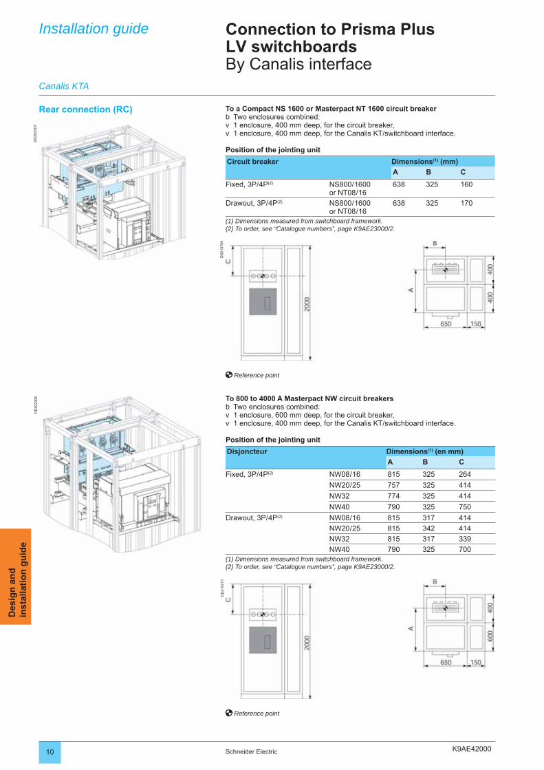
K9AE42000
DD
2023
07
DD
2107
69
DD
2023
05
DD
2107
71
10 Schneider Electric
Des
ign
an
din
stal
lati
on
gu
ide
Installation guide Connection to Prisma PlusLV switchboardsBy Canalis interface
Rear connection (RC) To a Compact NS 1600 or Masterpact NT 1600 circuit breakerTwo enclosures combined:1 enclosure, 400 mm deep, for the circuit breaker,1 enclosure, 400 mm deep, for the Canalis KT/switchboard interface.
Position of the jointing unit
Circuit breaker Dimensions(1) (mm)
A B C
Fixed, 3P / 4P(2) NS800 / 1600or NT08 / 16
638 325 160
Drawout, 3P / 4P(2) NS800 / 1600or NT08 / 16
638 325 170
(1) Dimensions measured from switchboard framework.(2) To order, see “Catalogue numbers”, page K9AE23000/2.
bvv
To 800 to 4000 A Masterpact NW circuit breakersTwo enclosures combined:1 enclosure, 600 mm deep, for the circuit breaker,1 enclosure, 400 mm deep, for the Canalis KT/switchboard interface.
Position of the jointing unit
Disjoncteur Dimensions(1) (en mm)
A B C
Fixed, 3P / 4P(2) NW08 / 16 815 325 264
NW20 / 25 757 325 414
NW32 774 325 414
NW40 790 325 750
Drawout, 3P / 4P(2) NW08 / 16 815 317 414
NW20 / 25 815 342 414
NW32 815 317 339
NW40 790 325 700(1) Dimensions measured from switchboard framework.(2) To order, see “Catalogue numbers”, page K9AE23000/2.
bvv
Reference point
Reference point
Canalis KTA
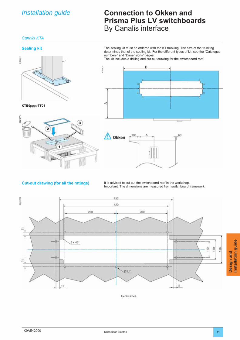
K9AE42000
DD
2023
14D
D21
0774
DD
2107
75
DD
2107
76
11Schneider Electric
Des
ign
an
din
stal
lati
on
gu
ide
Installation guide Connection to Okken andPrisma Plus LV switchboardsBy Canalis interface
The sealing kit must be ordered with the KT trunking. The size of the trunking determines that of the sealing kit. For the different types of kit, see the “Catalogue numbers” and “Dimensions” pages.The kit includes a drilling and cut-out drawing for the switchboard roof.
Sealing kit
Cut-out drawing (for all the ratings) It is advised to cut out the switchboard roof in the workshop.Important. The dimensions are measured from switchboard framework.
Centre lines.
Canalis KTA
KTB0ppppTT01
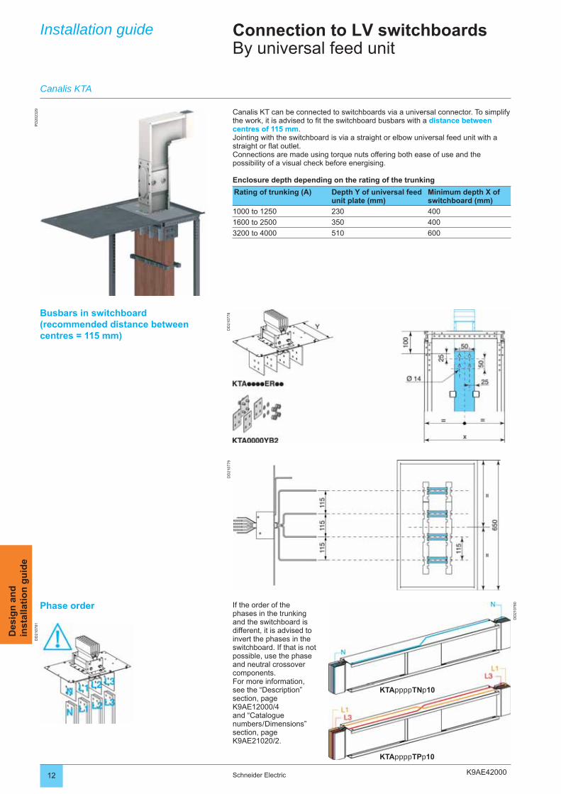
K9AE42000
PD
2023
29
DD
2107
78D
D21
0779
DD
2107
80
DD
2107
81
12 Schneider Electric
Des
ign
an
din
stal
lati
on
gu
ide
Installation guide Connection to LV switchboardsBy universal feed unit
Canalis KT can be connected to switchboards via a universal connector. To simplify the work, it is advised to fi t the switchboard busbars with a distance between centres of 115 mm.Jointing with the switchboard is via a straight or elbow universal feed unit with a straight or fl at outlet.Connections are made using torque nuts offering both ease of use and the possibility of a visual check before energising.
Enclosure depth depending on the rating of the trunking
Rating of trunking (A) Depth Y of universal feed unit plate (mm)
Minimum depth X of switchboard (mm)
1000 to 1250 230 400
1600 to 2500 350 400
3200 to 4000 510 600
Busbars in switchboard(recommended distance between centres = 115 mm)
Phase order If the order of the phases in the trunking and the switchboard is different, it is advised to invert the phases in the switchboard. If that is not possible, use the phase and neutral crossover components.For more information, see the “Description” section, page K9AE12000/4 and “Catalogue numbers / Dimensions” section, page K9AE21020/2.
Canalis KTA
KTAppppTNp10
KTAppppTPp10
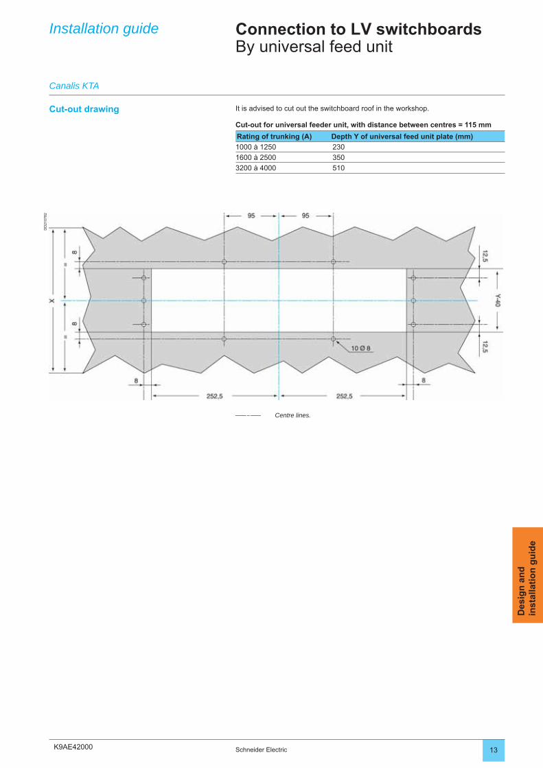
K9AE42000
DD
2107
82
13Schneider Electric
Des
ign
an
din
stal
lati
on
gu
ide
Installation guide Connection to LV switchboardsBy universal feed unit
Cut-out drawing It is advised to cut out the switchboard roof in the workshop.
Cut-out for universal feeder unit, with distance between centres = 115 mm
Rating of trunking (A) Depth Y of universal feed unit plate (mm)
1000 à 1250 230
1600 à 2500 350
3200 à 4000 510
Centre lines.
Canalis KTA
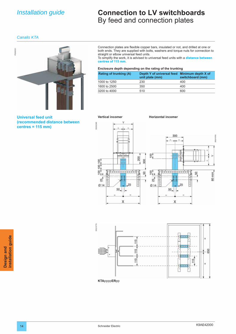
K9AE42000
PD
2023
31
DD
2107
83
DD
2107
79D
D20
2385
14 Schneider Electric
Des
ign
an
din
stal
lati
on
gu
ide
Installation guide Connection to LV switchboardsBy feed and connection plates
Connection plates are fl exible copper bars, insulated or not, and drilled at one or both ends. They are supplied with bolts, washers and torque nuts for connection to straight or elbow universal feed units.To simplify the work, it is advised to universal feed units with a distance between centres of 115 mm.
Enclosure depth depending on the rating of the trunking
Rating of trunking (A) Depth Y of universal feed unit plate (mm)
Minimum depth X of switchboard (mm)
1000 to 1250 230 400
1600 to 2500 350 400
3200 to 4000 510 600
Vertical incomer
Canalis KTA
Horizontal incomerUniversal feed unit(recommended distance between centres = 115 mm)
KTAppppERpp
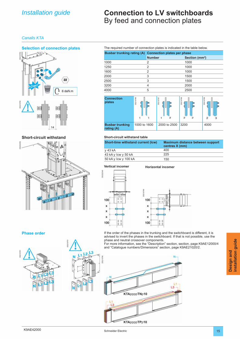
K9AE42000
DD
2107
85
DD
2107
90
DD
2107
91
DD
2107
80DD
2107
81D
D21
0764
DD
2023
59
DD
2023
49
15Schneider Electric
Des
ign
an
din
stal
lati
on
gu
ide
Short-circuit withstand Short-circuit withstand table
Short-time withstand current (Icw) Maximum distance between support centres X (mm)
y 43 kA 400
43 kA y Icw y 50 kA 225
50 kA y Icw y 100 kA 150
Phase order If the order of the phases in the trunking and the switchboard is different, it is advised to invert the phases in the switchboard. If that is not possible, use the phase and neutral crossover components.For more information, see the “Description” section, section, page K9AE12000/4 and “Catalogue numbers / Dimensions” section, page K9AE21020/2.
Installation guide Connection to LV switchboardsBy feed and connection plates
Canalis KTA
KTAppppTNp10
KTAppppTPp10
Vertical incomer Horizontal incomer
Selection of connection plates The required number of connection plates is indicated in the table below.
Busbar trunking rating (A) Connection plates per phase
Number Section (mm2)
1000 2 1000
1250 2 1000
1600 2 1000
2000 3 1500
2500 3 1500
3200 4 2000
4000 5 2500
Connectionplates
DD
2107
86
DD
2107
87
DD
2107
88
DD
2107
89
Busbar trunking rating (A)
1000 to 1600 2000 to 2500 3200 4000
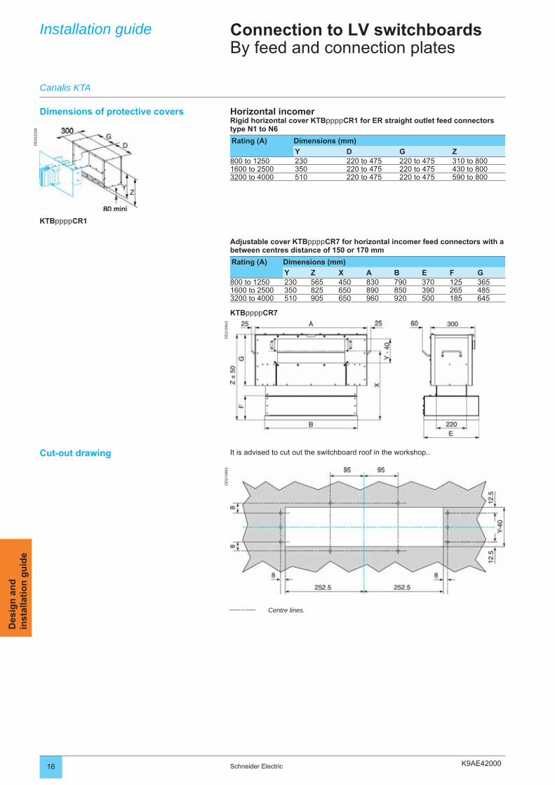
K9AE42000
DD
2023
26
DD
2109
53D
D21
0943
16 Schneider Electric
Des
ign
an
din
stal
lati
on
gu
ide
Installation guide Connection to LV switchboardsBy feed and connection plates
Dimensions of protective covers Horizontal incomerRigid horizontal cover KTBppppCR1 for ER straight outlet feed connectors type N1 to N6
Rating (A) Dimensions (mm)
Y D G Z800 to 1250 230 220 to 475 220 to 475 310 to 8001600 to 2500 350 220 to 475 220 to 475 430 to 8003200 to 4000 510 220 to 475 220 to 475 590 to 800
Canalis KTA
Adjustable cover KTBppppCR7 for horizontal incomer feed connectors with a between centres distance of 150 or 170 mm
Rating (A) Dimensions (mm)
Y Z X A B E F G800 to 1250 230 565 450 830 790 370 125 3651600 to 2500 350 825 650 890 850 390 265 4853200 to 4000 510 905 650 960 920 500 185 645
KTBppppCR7
KTBppppCR1
Cut-out drawing It is advised to cut out the switchboard roof in the workshop..
Centre lines.
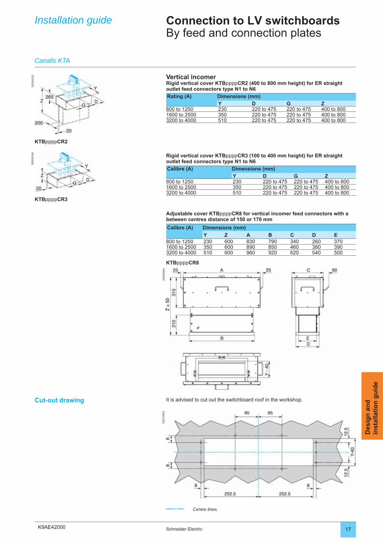
K9AE42000
DD
2023
22D
D20
2324
DD
2029
44D
D21
0953
17Schneider Electric
Des
ign
an
din
stal
lati
on
gu
ide
Cut-out drawing It is advised to cut out the switchboard roof in the workshop.
Centre lines.
Installation guide
Canalis KTA
Connection to LV switchboardsBy feed and connection plates
Rigid vertical cover KTBppppCR3 (100 to 400 mm height) for ER straight outlet feed connectors type N1 to N6
Calibre (A) Dimensions (mm)
Y D G Z800 to 1250 230 220 to 475 220 to 475 400 to 8001600 to 2500 350 220 to 475 220 to 475 400 to 8003200 to 4000 510 220 to 475 220 to 475 400 to 800
Adjustable cover KTBppppCR8 for vertical incomer feed connectors with a between centres distance of 150 or 170 mm
Calibre (A) Dimensions (mm)
Y Z A B C D E800 to 1250 230 600 830 790 340 260 3701600 to 2500 350 600 890 850 460 380 3903200 to 4000 510 600 960 920 620 540 500
KTBppppCR8
KTBppppCR3
Vertical incomerRigid vertical cover KTBppppCR2 (400 to 800 mm height) for ER straight outlet feed connectors type N1 to N6
Rating (A) Dimensions (mm)
Y D G Z800 to 1250 230 220 to 475 220 to 475 400 to 8001600 to 2500 350 220 to 475 220 to 475 400 to 8003200 to 4000 510 220 to 475 220 to 475 400 to 800
KTBppppCR2
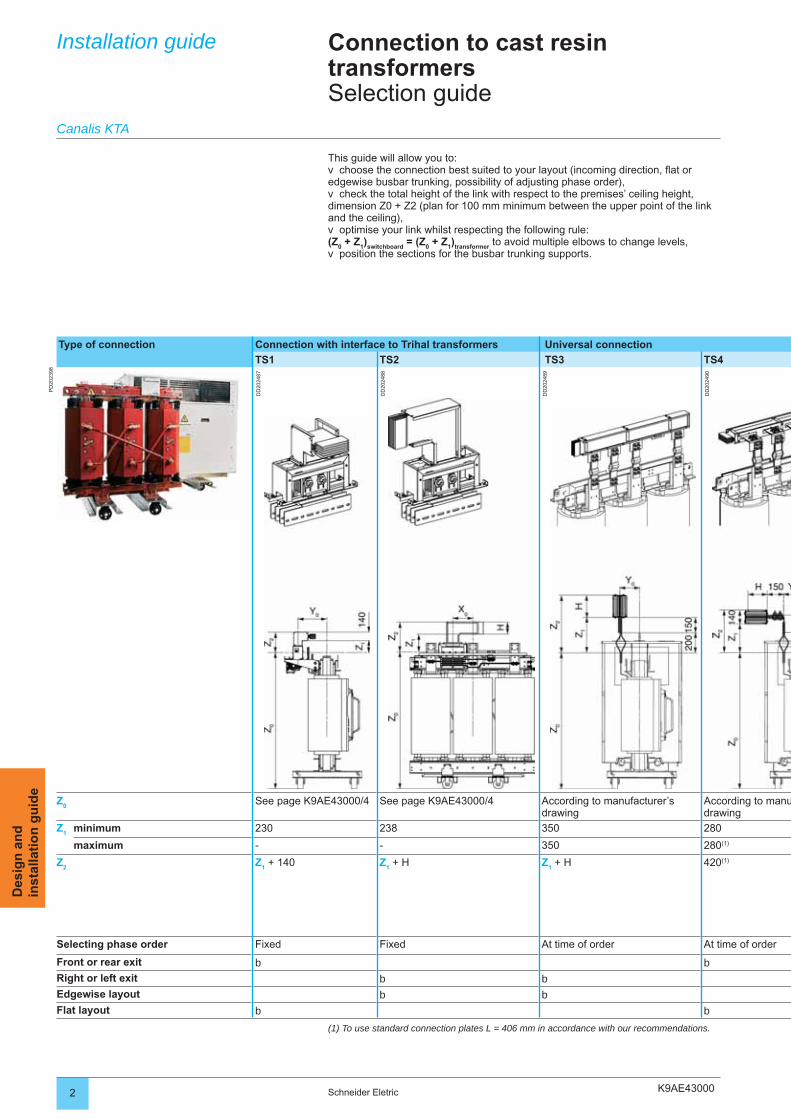
K9AE430002 Schneider Eletric
Des
ign
an
din
stal
lati
on
gu
ide
Installation guide Connection to cast resin transformersSelection guide
Type of connection Connection with interface to Trihal transformers Universal connection
TS1 TS2 TS3 TS4
PD
2023
98
DD
2024
87
DD
2024
88
DD
2024
89
DD
2024
90
Z0
See page K9AE43000/4 See page K9AE43000/4 According to manufacturer’s drawing
According to manudrawing
Z1 minimum 230 238 350 280
maximum - - 350 280(1)
Z2
Z1 + 140 Z
1 + H Z
1 + H 420(1)
Selecting phase order Fixed Fixed At time of order At time of order
Front or rear exit b bRight or left exit b bEdgewise layout b bFlat layout b b
Canalis KTA
This guide will allow you to:choose the connection best suited to your layout (incoming direction, fl at or
edgewise busbar trunking, possibility of adjusting phase order),check the total height of the link with respect to the premises’ ceiling height,
dimension Z0 + Z2 (plan for 100 mm minimum between the upper point of the link and the ceiling),
optimise your link whilst respecting the following rule: (Z
0 + Z
1)
switchboard = (Z
0 + Z
1)
transformer to avoid multiple elbows to change levels,
position the sections for the busbar trunking supports.
v
v
v
v
(1) To use standard connection plates L = 406 mm in accordance with our recommendations.
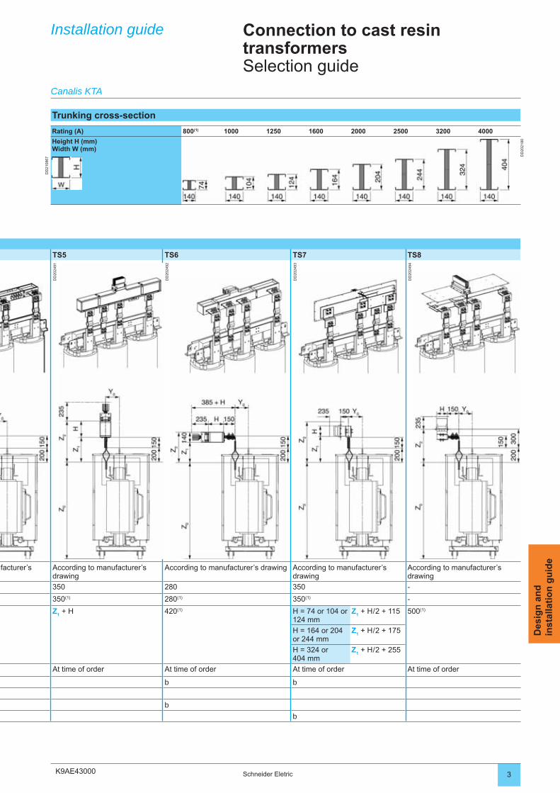
K9AE43000 3Schneider Eletric
Des
ign
an
din
stal
lati
on
gu
ide
TS5 TS6 TS7 TS8
DD
2024
91
DD
2024
92
DD
2024
93
DD
2024
94
ufacturer’s According to manufacturer’s drawing
According to manufacturer’s drawing According to manufacturer’s drawing
According to manufacturer’s drawing
350 280 350 -
350(1) 280(1) 350(1) -
Z1 + H 420(1) H = 74 or 104 or
124 mmZ
1 + H / 2 + 115 500(1)
H = 164 or 204 or 244 mm
Z1 + H / 2 + 175
H = 324 or404 mm
Z1 + H / 2 + 255
At time of order At time of order At time of order At time of order
b b
b
b
Installation guide Connection to cast resin transformersSelection guide
Canalis KTA
Trunking cross-section
Rating (A) 800(1) 1000 1250 1600 2000 2500 3200 4000
Height H (mm)Width W (mm)
DD
2021
80
DD
2108
67
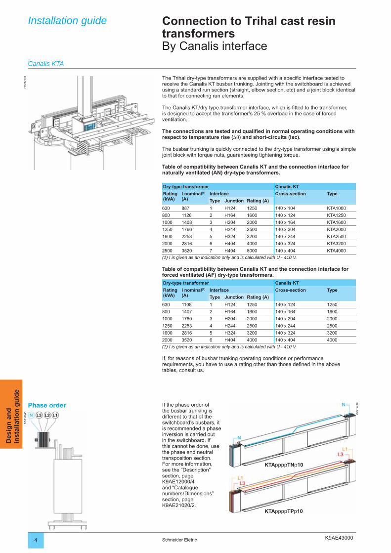
K9AE43000
PD
2025
03D
D21
0945 DD
2107
80
4 Schneider Eletric
Des
ign
an
din
stal
lati
on
gu
ide
Installation guide Connection to Trihal cast resin transformersBy Canalis interface
The Trihal dry-type transformers are supplied with a specifi c interface tested to receive the Canalis KT busbar trunking. Jointing with the switchboard is achieved using a standard run section (straight, elbow section, etc) and a joint block identical to that for connecting run elements.
The Canalis KT / dry type transformer interface, which is fi tted to the transformer, is designed to accept the transformer’s 25 % overload in the case of forced ventilation.
The connections are tested and qualifi ed in normal operating conditions with respect to temperature rise (Δθ) and short-circuits (Isc).
The busbar trunking is quickly connected to the dry-type transformer using a simple joint block with torque nuts, guaranteeing tightening torque.
Table of compatibility between Canalis KT and the connection interface for naturally ventilated (AN) dry-type transformers.
Dry-type transformer Canalis KT
Rating (kVA)
l nominal(1)
(A)Interface Cross-section Type
Type Junction Rating (A)
630 887 1 H124 1250 140 x 104 KTA1000
800 1126 2 H164 1600 140 x 124 KTA1250
1000 1408 3 H204 2000 140 x 164 KTA1600
1250 1760 4 H244 2500 140 x 204 KTA2000
1600 2253 5 H324 3200 140 x 244 KTA2500
2000 2816 6 H404 4000 140 x 324 KTA3200
2500 3520 7 H404 5000 140 x 404 KTA4000
(1) I is given as an indication only and is calculated with U - 410 V.
Table of compatibility between Canalis KT and the connection interface for forced ventilated (AF) dry-type transformers.
Dry-type transformer Canalis KT
Rating (kVA)
l nominal(1)
(A)Interface Cross-section Type
Type Junction Rating (A)
630 1108 1 H124 1250 140 x 124 1250
800 1407 2 H164 1600 140 x 164 1600
1000 1760 3 H204 2000 140 x 204 2000
1250 2253 4 H244 2500 140 x 244 2500
1600 2816 5 H324 3200 140 x 324 3200
2000 3520 6 H404 4000 140 x 404 4000
(1) I is given as an indication only and is calculated with U - 410 V.
If, for reasons of busbar trunking operating conditions or performance requirements, you have to use a rating other than those defi ned in the above tables, consult us.
Canalis KTA
Phase order If the phase order of the busbar trunking is different to that of the switchboard’s busbars, it is recommended a phase inversion is carried out in the switchboard. If this cannot be done, use the phase and neutral transposition section.For more information, see the “Description” section, page K9AE12000/4 and “Catalogue numbers / Dimensions” section, page K9AE21020/2.
KTAppppTNp10
KTAppppTPp10
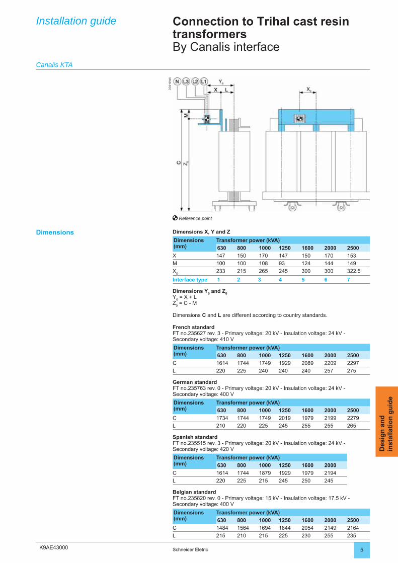
K9AE43000
DD
2109
46
5Schneider Eletric
Des
ign
an
din
stal
lati
on
gu
ide
Installation guide Connection to Trihal cast resin transformersBy Canalis interface
Dimensions X, Y and Z
Dimensions (mm)
Transformer power (kVA)
630 800 1000 1250 1600 2000 2500
X 147 150 170 147 150 170 153
M 100 100 108 93 124 144 149
X0
233 215 265 245 300 300 322.5
Interface type 1 2 3 4 5 6 7
Dimensions Y0 and Z
0Y
0 = X + L
Z0 = C - M
Dimensions C and L are different according to country standards.
French standardFT no.235627 rev. 3 - Primary voltage: 20 kV - Insulation voltage: 24 kV -Secondary voltage: 410 V
Dimensions (mm)
Transformer power (kVA)
630 800 1000 1250 1600 2000 2500
C 1614 1744 1749 1929 2089 2209 2297
L 220 225 240 240 240 257 275
German standardFT no.235763 rev. 0 - Primary voltage: 20 kV - Insulation voltage: 24 kV - Secondary voltage: 400 V
Dimensions (mm)
Transformer power (kVA)
630 800 1000 1250 1600 2000 2500
C 1734 1744 1749 2019 1979 2199 2279
L 210 220 225 245 255 255 265
Spanish standardFT no.235515 rev. 3 - Primary voltage: 20 kV - Insulation voltage: 24 kV - Secondary voltage: 420 V
Dimensions (mm)
Transformer power (kVA)
630 800 1000 1250 1600 2000
C 1614 1744 1879 1929 1979 2194
L 220 225 215 245 250 245
Belgian standardFT no.235820 rev. 0 - Primary voltage: 15 kV - Insulation voltage: 17.5 kV - Secondary voltage: 400 V
Dimensions (mm)
Transformer power (kVA)
630 800 1000 1250 1600 2000 2500
C 1484 1564 1694 1844 2054 2149 2164
L 215 210 215 225 230 255 235
Dimensions
Canalis KTA
Reference point
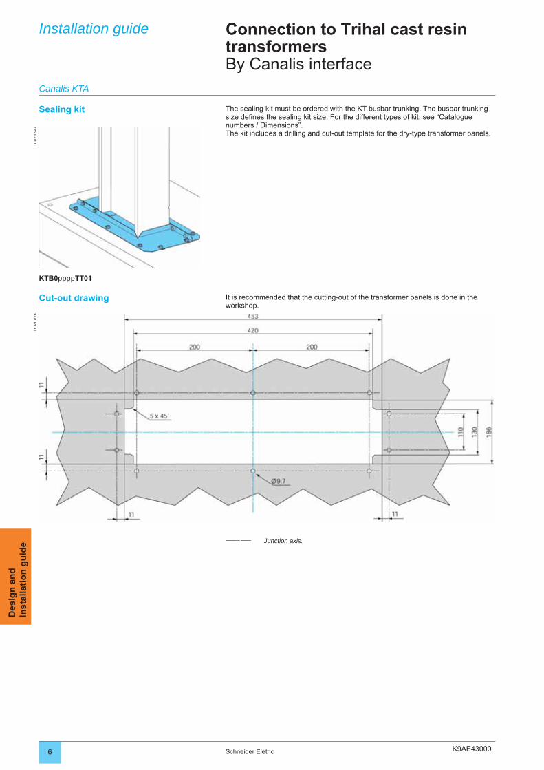
K9AE43000
DD
2109
47D
D21
0776
6 Schneider Eletric
Des
ign
an
din
stal
lati
on
gu
ide
Installation guide Connection to Trihal cast resin transformersBy Canalis interface
The sealing kit must be ordered with the KT busbar trunking. The busbar trunking size defi nes the sealing kit size. For the different types of kit, see “Catalogue numbers / Dimensions”.The kit includes a drilling and cut-out template for the dry-type transformer panels.
Sealing kit
Cut-out drawing It is recommended that the cutting-out of the transformer panels is done in the workshop.
Junction axis.
Canalis KTA
KTB0ppppTT01
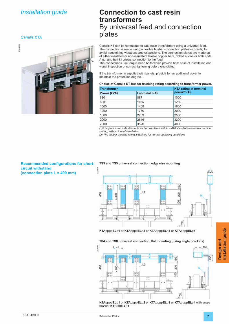
K9AE43000
PD
2023
30
DD
2109
49D
D21
0948
7Schneider Eletric
Des
ign
an
din
stal
lati
on
gu
ide
Installation guide Connection to cast resin transformersBy universal feed and connection plates
Canalis KT can be connected to cast resin transformers using a universal feed.The connection is made using a fl exible busbar (connection plates or braids) to avoid transmitting vibrations and expansions. The connection plates are made up of either insulated or non-insulated fl exible copper bars, drilled at one or both ends. A nut and bolt kit allows connection to the feed.The connections use torque-head bolts which provide both ease of installation and visual inspection of correct tightening before energising.
If the transformer is supplied with panels, provide for an additional cover to maintain the protection degree.
Choice of Canalis KT busbar trunking rating according to transformer power.
Transformer KTA rating at nominal power(2) (A)Power (kVA) I nominal(1) (A)
630 887 1000
800 1126 1250
1000 1408 1600
1250 1760 2000
1600 2253 2500
2000 2816 3200
2500 3520 4000(1) I is given as an indication only and is calculated with U = 410 V and at transformer nominal setting, without forced ventilation.(2) The busbar trunking rating is defi ned for normal operating conditions.
Recommended confi gurations for short-circuit withstand(connection plate L = 400 mm)
Canalis KTA
TS3 and TS5 universal connection, edgewise mounting
KTAppppELp1 or KTAppppELp2 or KTAppppELp3 or KTAppppELp4
TS4 and TS6 universal connection, fl at mounting (using angle brackets)
KTAppppELp1 or KTAppppELp2 or KTAppppELp3 or KTAppppELp4 with angle bracket KTB0000YE1
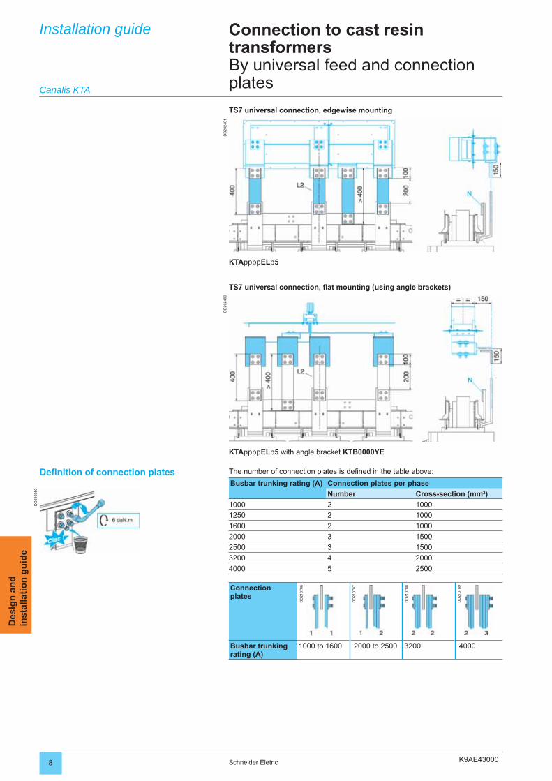
K9AE43000
DD
2024
81D
D20
2480
DD
2109
50
8 Schneider Eletric
Des
ign
an
din
stal
lati
on
gu
ide
Installation guide Connection to cast resin transformersBy universal feed and connection platesCanalis KTA
KTAppppELp5 with angle bracket KTB0000YE
Defi nition of connection plates The number of connection plates is defi ned in the table above:
Busbar trunking rating (A) Connection plates per phase
Number Cross-section (mm2)
1000 2 1000
1250 2 1000
1600 2 1000
2000 3 1500
2500 3 1500
3200 4 2000
4000 5 2500
Connectionplates
DD
2107
86
DD
2107
87
DD
2107
88
DD
2107
89
Busbar trunking rating (A)
1000 to 1600 2000 to 2500 3200 4000
TS7 universal connection, edgewise mounting
KTAppppELp5
TS7 universal connection, fl at mounting (using angle brackets)
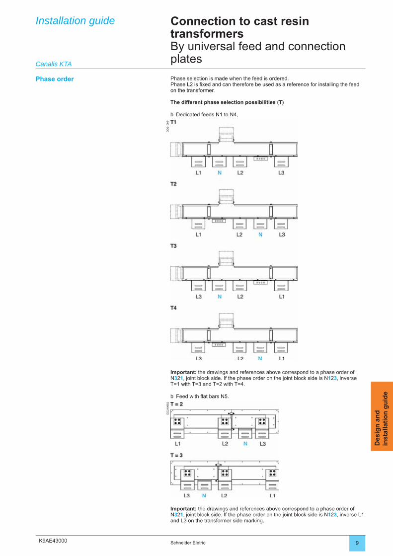
K9AE43000
DD
2109
51D
D21
0952
9Schneider Eletric
Des
ign
an
din
stal
lati
on
gu
ide
Installation guide
Canalis KTA
Phase order
Connection to cast resin transformersBy universal feed and connection plates
Phase selection is made when the feed is ordered.Phase L2 is fi xed and can therefore be used as a reference for installing the feed on the transformer.
The different phase selection possibilities (T)
Dedicated feeds N1 to N4,b
Important: the drawings and references above correspond to a phase order of N321, joint block side. If the phase order on the joint block side is N123, inverse T=1 with T=3 and T=2 with T=4.
Feed with fl at bars N5.b
Important: the drawings and references above correspond to a phase order of N321, joint block side. If the phase order on the joint block side is N123, inverse L1 and L3 on the transformer side marking.
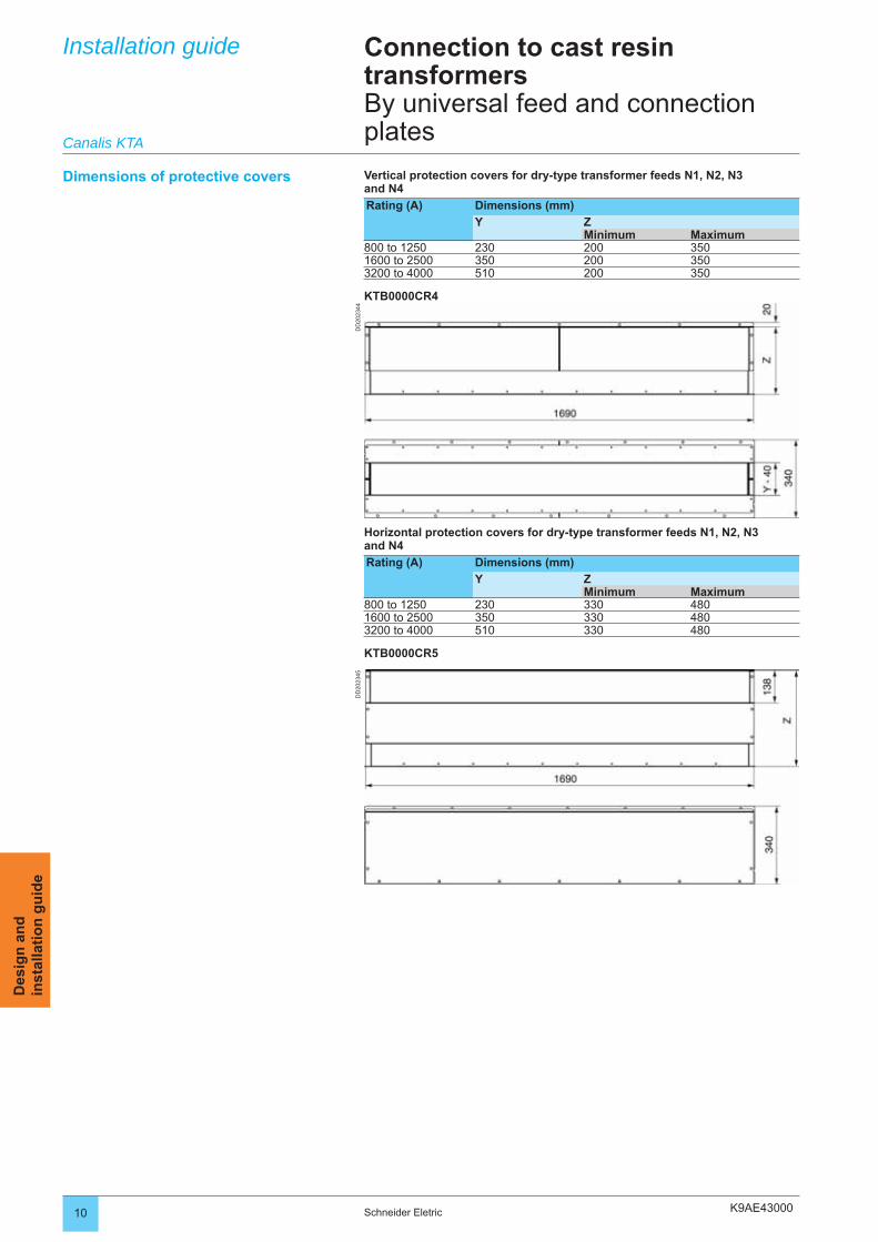
K9AE43000
DD
2023
45D
D20
2344
10 Schneider Eletric
Des
ign
an
din
stal
lati
on
gu
ide
Installation guide Connection to cast resin transformersBy universal feed and connection plates
Dimensions of protective covers Vertical protection covers for dry-type transformer feeds N1, N2, N3 and N4
Rating (A) Dimensions (mm)
Y ZMinimum Maximum
800 to 1250 230 200 3501600 to 2500 350 200 3503200 to 4000 510 200 350
KTB0000CR4
Canalis KTA
Horizontal protection covers for dry-type transformer feeds N1, N2, N3 and N4
Rating (A) Dimensions (mm)
Y ZMinimum Maximum
800 to 1250 230 330 4801600 to 2500 350 330 4803200 to 4000 510 330 480
KTB0000CR5
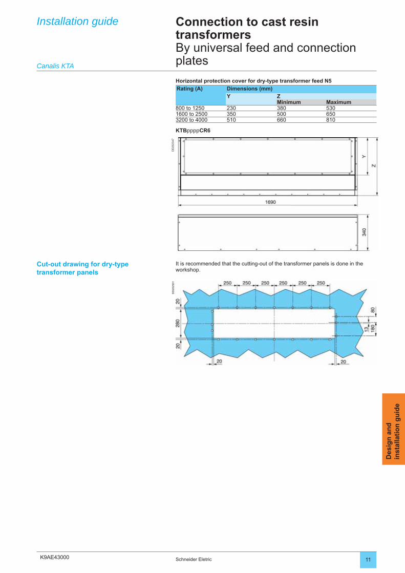
K9AE43000
DD
2023
47D
D20
2501
11Schneider Eletric
Des
ign
an
din
stal
lati
on
gu
ide
Cut-out drawing for dry-type transformer panels
It is recommended that the cutting-out of the transformer panels is done in the workshop.
Installation guide
Canalis KTA
Connection to cast resin transformersBy universal feed and connection plates
Horizontal protection cover for dry-type transformer feed N5
Rating (A) Dimensions (mm)
Y ZMinimum Maximum
800 to 1250 230 380 5301600 to 2500 350 500 6503200 to 4000 510 660 810
KTBppppCR6
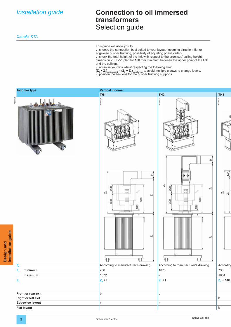
K9AE440002 Schneider Electric
Des
ign
an
din
stal
lati
on
gu
ide
Installation guide Connection to oil immersed transformersSelection guide
Incomer type Vertical incomer
TH1 TH2 TH3
PD
2024
29
DD
2024
16
DD
2024
17
DD
2024
18
Z0
According to manufacturer’s drawing According to manufacturer’s drawing According
Z1 minimum 738 1073 730
maximum 1072 - 1064
Z2
Z1 + H Z
1 + H Z
1 + 140
Front or rear exit b b
Right or left exit b
Edgewise layout b b
Flat layout b
Canalis KTA
This guide will allow you to:choose the connection best suited to your layout (incoming direction, fl at or
edgewise busbar trunking, possibility of adjusting phase order),check the total height of the link with respect to the premises’ ceiling height,
dimension Z0 + Z2 (plan for 100 mm minimum between the upper point of the link and the ceiling),
optimise your link whilst respecting the following rule: (Z
0 + Z
1)
switchboard = (Z
0 + Z
1)
transformer to avoid multiple elbows to change levels,
position the sections for the busbar trunking supports.
v
v
v
v
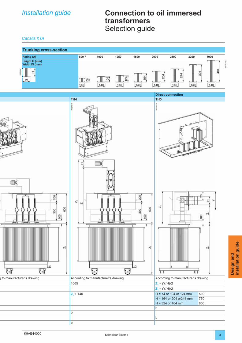
K9AE44000 3Schneider Electric
Des
ign
an
din
stal
lati
on
gu
ide
Direct connection
TH4 TH5
DD
2024
19
DD
2024
20
g to manufacturer’s drawing According to manufacturer’s drawing According to manufacturer’s drawing
1065 Z1 = (Y / H) / 2
- Z1 = (Y / H) / 2
Z1 + 140 H = 74 or 104 or 124 mm 510
H = 164 or 204 or244 mm 770
H = 324 or 404 mm 850b
b
b
b
Installation guide Connection to oil immersed transformersSelection guide
Canalis KTA
Trunking cross-section
Rating (A) 800(1) 1000 1250 1600 2000 2500 3200 4000
Height H (mm)Width W (mm)
DD
2021
80
DD
2108
67
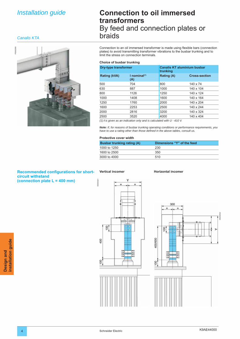
K9AE44000
DD
2024
21
DD
2024
22
PD
2023
00
4 Schneider Electric
Des
ign
an
din
stal
lati
on
gu
ide
Installation guide Connection to oil immersed transformersBy feed and connection plates or braids
Connection to an oil immersed transformer is made using fl exible bars (connection plates) to avoid transmitting transformer vibrations to the busbar trunking and to limit the stress on connection terminals.
Choice of busbar trunking
Dry-type transformer Canalis KT aluminium busbar trunking
Rating (kVA) l nominal(1)
(A)Rating (A) Cross-section
500 704 800 140 x 74
630 887 1000 140 x 104
800 1126 1250 140 x 124
1000 1408 1600 140 x 164
1250 1760 2000 140 x 204
1600 2253 2500 140 x 244
2000 2816 3200 140 x 324
2500 3520 4000 140 x 404(1) I is given as an indication only and is calculated with U - 410 V.
Note: If, for reasons of busbar trunking operating conditions or performance requirements, you have to use a rating other than those defi ned in the above tables, consult us.
Protective cover width
Busbar trunking rating (A) Dimensions “Y” of the feed
1000 to 1250 230
1600 to 2500 350
3000 to 4000 510
Canalis KTA
Vertical incomer Horizontal incomerRecommended confi gurations for short-circuit withstand(connection plate L = 400 mm)
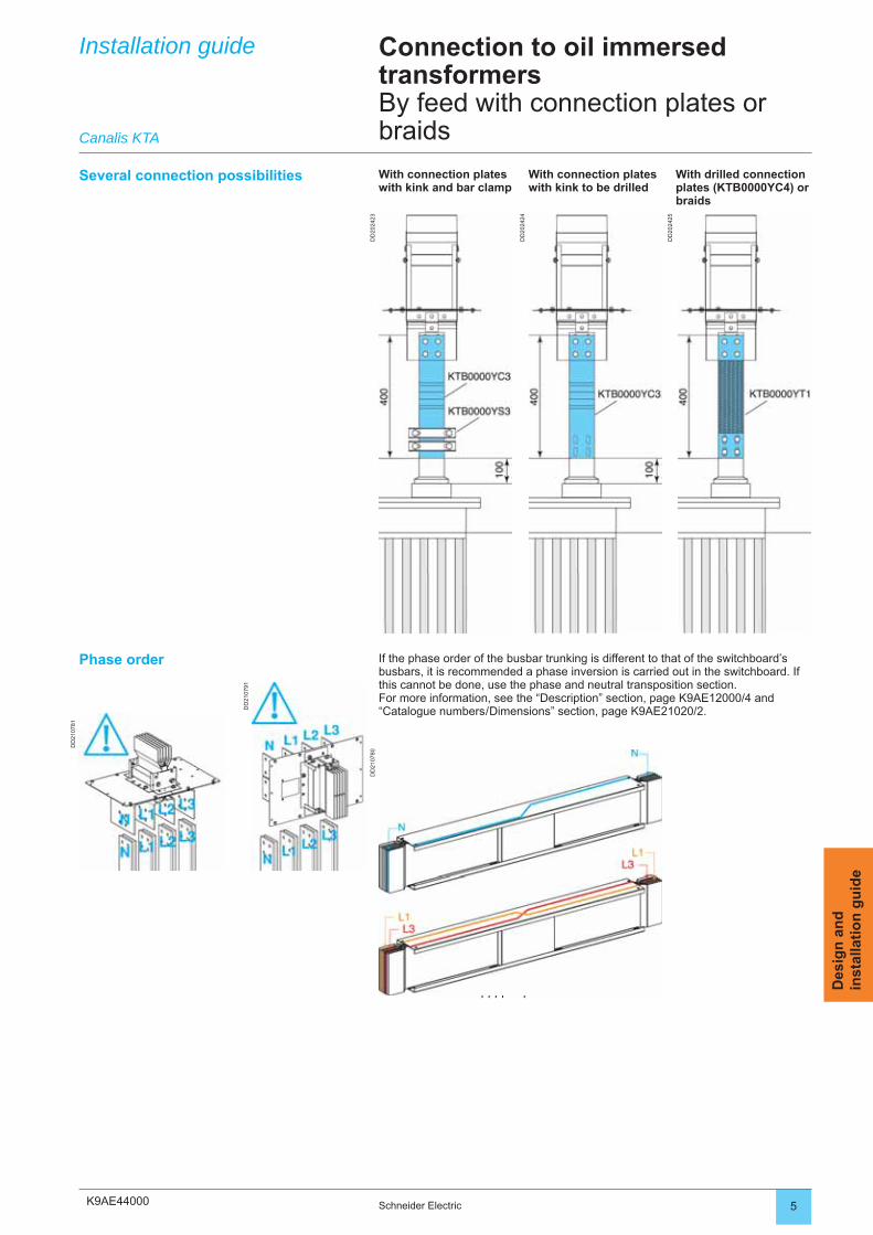
K9AE44000
KTAppppTNp10
KTAppppTPp10
DD
2024
23
DD
2024
24
DD
2024
25
DD
2107
91
DD
2107
81
DD
2107
80
5Schneider Electric
Des
ign
an
din
stal
lati
on
gu
ide
Installation guide
Canalis KTA
Connection to oil immersed transformersBy feed with connection plates or braids
Several connection possibilities With connection plates with kink and bar clamp
With connection plates with kink to be drilled
With drilled connection plates (KTB0000YC4) or braids
Phase order If the phase order of the busbar trunking is different to that of the switchboard’s busbars, it is recommended a phase inversion is carried out in the switchboard. If this cannot be done, use the phase and neutral transposition section.For more information, see the “Description” section, page K9AE12000/4 and “Catalogue numbers / Dimensions” section, page K9AE21020/2.
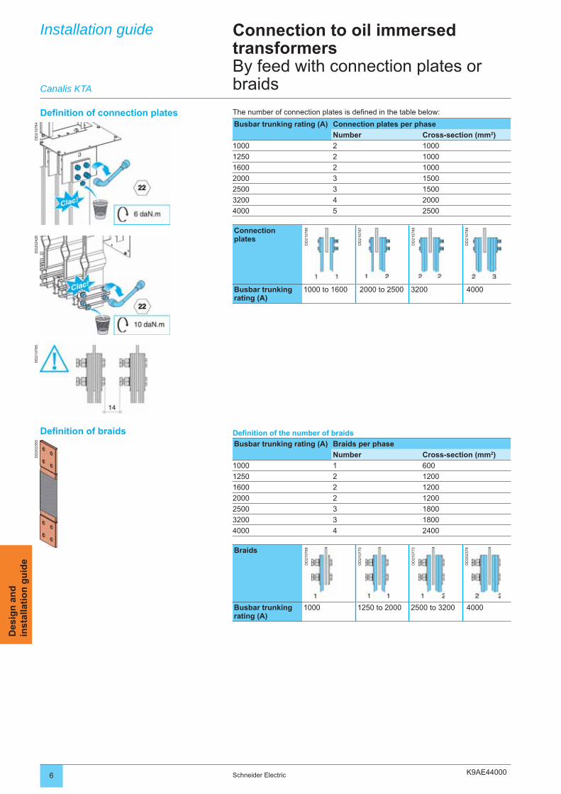
K9AE44000
DD
2023
55D
D21
0764
DD
2024
26D
D21
0785
6 Schneider Electric
Des
ign
an
din
stal
lati
on
gu
ide
Defi nition of connection plates The number of connection plates is defi ned in the table below:
Busbar trunking rating (A) Connection plates per phase
Number Cross-section (mm2)
1000 2 1000
1250 2 1000
1600 2 1000
2000 3 1500
2500 3 1500
3200 4 2000
4000 5 2500
Connectionplates
DD
2107
86
DD
2107
87
DD
2107
88
DD
2107
89
Busbar trunking rating (A)
1000 to 1600 2000 to 2500 3200 4000
Defi nition of the number of braids
Busbar trunking rating (A) Braids per phase
Number Cross-section (mm2)
1000 1 600
1250 2 1200
1600 2 1200
2000 2 1200
2500 3 1800
3200 3 1800
4000 4 2400
Braids
DD
2107
68
DD
2107
70
DD
2107
73
DD
2023
76
Busbar trunking rating (A)
1000 1250 to 2000 2500 to 3200 4000
Defi nition of braids
Installation guide
Canalis KTA
Connection to oil immersed transformersBy feed with connection plates or braids
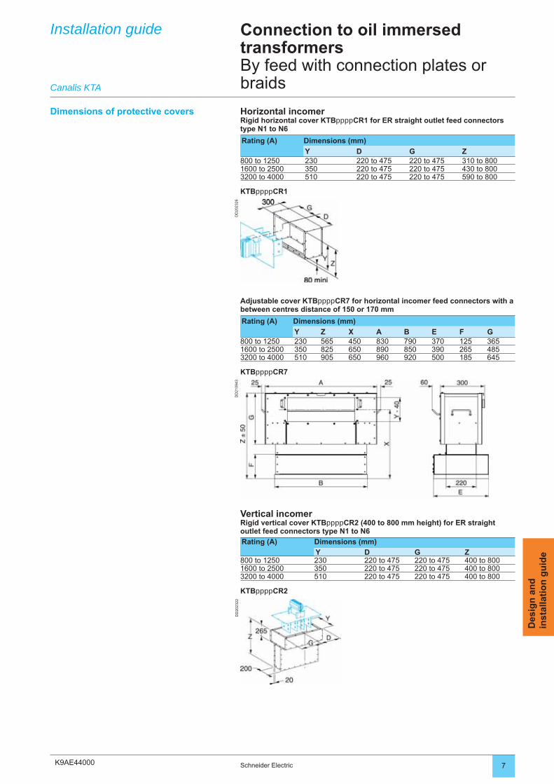
K9AE44000
DD
2023
26D
D20
2322
DD
2109
43
7Schneider Electric
Des
ign
an
din
stal
lati
on
gu
ide
Installation guide Connection to oil immersed transformersBy feed with connection plates or braids
Dimensions of protective covers Horizontal incomerRigid horizontal cover KTBppppCR1 for ER straight outlet feed connectors type N1 to N6
Rating (A) Dimensions (mm)
Y D G Z800 to 1250 230 220 to 475 220 to 475 310 to 8001600 to 2500 350 220 to 475 220 to 475 430 to 8003200 to 4000 510 220 to 475 220 to 475 590 to 800
KTBppppCR1
Canalis KTA
Adjustable cover KTBppppCR7 for horizontal incomer feed connectors with a between centres distance of 150 or 170 mm
Rating (A) Dimensions (mm)
Y Z X A B E F G800 to 1250 230 565 450 830 790 370 125 3651600 to 2500 350 825 650 890 850 390 265 4853200 to 4000 510 905 650 960 920 500 185 645
KTBppppCR7
Vertical incomerRigid vertical cover KTBppppCR2 (400 to 800 mm height) for ER straight outlet feed connectors type N1 to N6
Rating (A) Dimensions (mm)
Y D G Z800 to 1250 230 220 to 475 220 to 475 400 to 8001600 to 2500 350 220 to 475 220 to 475 400 to 8003200 to 4000 510 220 to 475 220 to 475 400 to 800
KTBppppCR2
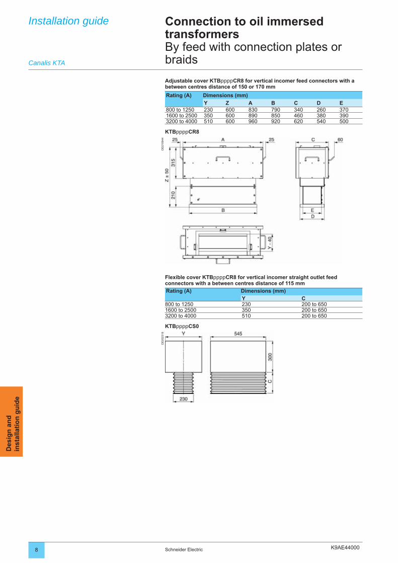
K9AE44000
DD
2109
44D
D20
2319
8 Schneider Electric
Des
ign
an
din
stal
lati
on
gu
ide
Installation guide Connection to oil immersed transformersBy feed with connection plates or braidsCanalis KTA
Adjustable cover KTBppppCR8 for vertical incomer feed connectors with a between centres distance of 150 or 170 mm
Rating (A) Dimensions (mm)
Y Z A B C D E800 to 1250 230 600 830 790 340 260 3701600 to 2500 350 600 890 850 460 380 3903200 to 4000 510 600 960 920 620 540 500
KTBppppCR8
Flexible cover KTBppppCR8 for vertical incomer straight outlet feed connectors with a between centres distance of 115 mm
Rating (A) Dimensions (mm)
Y C800 to 1250 230 200 to 6501600 to 2500 350 200 to 6503200 to 4000 510 200 to 650
KTBppppCS0
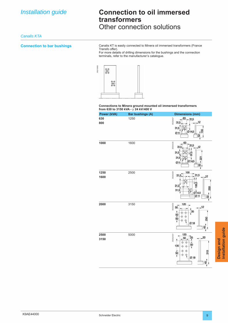
K9AE44000
DD
2109
55
9Schneider Electric
Des
ign
an
din
stal
lati
on
gu
ide
Installation guide Connection to oil immersed transformersOther connection solutions
Canalis KTA
Connection to bar bushings Canalis KT is easily connected to Minera oil immersed transformers (France Transfo offer).For more details of drilling dimensions for the bushings and the connection terminals, refer to the manufacturer’s catalogue.
Connections to Minera ground mounted oil immersed transformers from 630 to 3150 kVA - y 24 kV / 400 V
Power (kVA) Bar bushings (A) Dimensions (mm)
630 1250
DD
2024
27
800
1000 1600
DD
2024
281250 2500
DD
2024
29
1600
2000 3150
DD
2024
30
2500 5000
DD
2024
321
3150
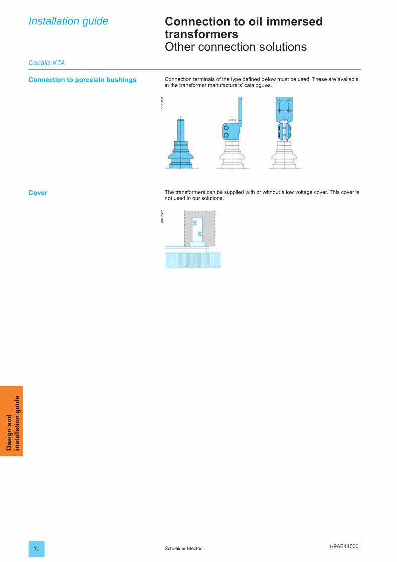
K9AE44000
DD
2109
59D
D21
0957
10 Schneider Electric
Des
ign
an
din
stal
lati
on
gu
ide
Connection to porcelain bushings Connection terminals of the type defi ned below must be used. These are available in the transformer manufacturers’ catalogues.
Cover The transformers can be supplied with or without a low voltage cover. This cover is not used in our solutions.
Installation guide
Canalis KTA
Connection to oil immersed transformersOther connection solutions

K9AE44000 11Schneider Electric
Des
ign
an
din
stal
lati
on
gu
ide
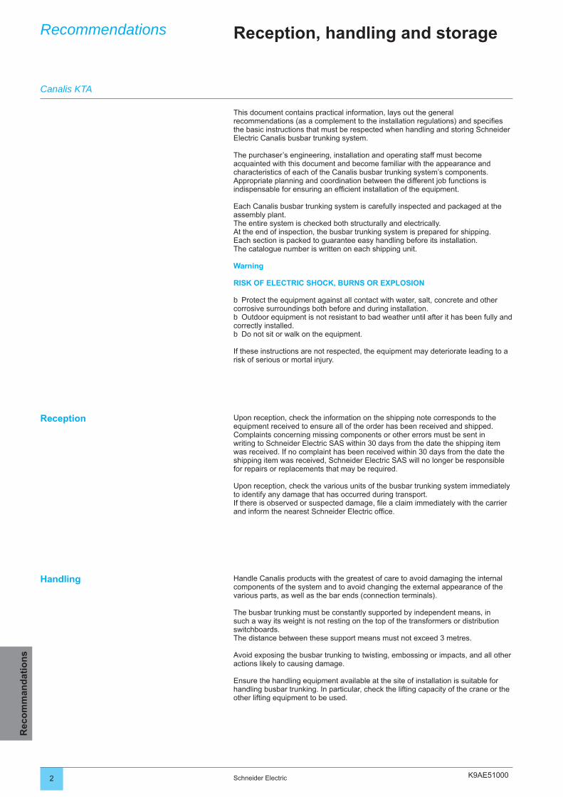
K9AE510002 Schneider Electric
Rec
om
man
dat
ion
sRecommendations Reception, handling and storage
Reception Upon reception, check the information on the shipping note corresponds to the equipment received to ensure all of the order has been received and shipped.Complaints concerning missing components or other errors must be sent in writing to Schneider Electric SAS within 30 days from the date the shipping item was received. If no complaint has been received within 30 days from the date the shipping item was received, Schneider Electric SAS will no longer be responsible for repairs or replacements that may be required.
Upon reception, check the various units of the busbar trunking system immediately to identify any damage that has occurred during transport. If there is observed or suspected damage, fi le a claim immediately with the carrier and inform the nearest Schneider Electric offi ce.
Handling Handle Canalis products with the greatest of care to avoid damaging the internal components of the system and to avoid changing the external appearance of the various parts, as well as the bar ends (connection terminals).
The busbar trunking must be constantly supported by independent means, in such a way its weight is not resting on the top of the transformers or distribution switchboards. The distance between these support means must not exceed 3 metres.
Avoid exposing the busbar trunking to twisting, embossing or impacts, and all other actions likely to causing damage.
Ensure the handling equipment available at the site of installation is suitable for handling busbar trunking. In particular, check the lifting capacity of the crane or the other lifting equipment to be used.
Canalis KTA
This document contains practical information, lays out the general recommendations (as a complement to the installation regulations) and specifi es the basic instructions that must be respected when handling and storing Schneider Electric Canalis busbar trunking system.
The purchaser’s engineering, installation and operating staff must become acquainted with this document and become familiar with the appearance and characteristics of each of the Canalis busbar trunking system’s components.Appropriate planning and coordination between the different job functions is indispensable for ensuring an effi cient installation of the equipment.
Each Canalis busbar trunking system is carefully inspected and packaged at the assembly plant.The entire system is checked both structurally and electrically. At the end of inspection, the busbar trunking system is prepared for shipping. Each section is packed to guarantee easy handling before its installation. The catalogue number is written on each shipping unit.
Warning
RISK OF ELECTRIC SHOCK, BURNS OR EXPLOSION
Protect the equipment against all contact with water, salt, concrete and other corrosive surroundings both before and during installation.
Outdoor equipment is not resistant to bad weather until after it has been fully and correctly installed.
Do not sit or walk on the equipment.
If these instructions are not respected, the equipment may deteriorate leading to a risk of serious or mortal injury.
b
b
b
K9AE51000 3Schneider Electric
Rec
om
man
dat
ion
s
Reception, handling and storageRecommendations
Take great care when unpacking the equipment:use a nail-head puller when unpacking wooden crates, if hauling the busbar trunking with a crane, use Nylon slings to spread the weight
of the unit being lifted,if using cables, insert a spacing means to avoid damaging the busbar trunking,if using a forklift truck, position the busbar trunking on the forks in such a way the
weight is evenly distributed.
1 - Cut the strapping holding the packaging case using suitable cutting tools.
2 - Use suitable tools to remove the strengthened steel packaging at each end of the busbar trunking. Take care not to damage the steel box so as not to damage the busbar trunking. Avoid the use of objects with sharp edges when lifting the busbar trunking.
3 - Dispose of all used packaging in an appropriate way.
Never drag the busbar trunking along the fl oor. Do not use the end bars to lift sections of the busbar trunking.
bb
bb
Protection against humidity during storage
If the busbar trunking is not installed and commissioned immediately, leave it in the original Canalis packaging and store it in a clean and dry place at a uniform temperature.
The busbar trunking must not be stored outside. However, if outside storage is necessary, cover the busbar trunking in such a way as to protect it from bad weather and to avoid contact with the elements.
Temporary electrical heating must be provided for underneath the covering means to prevent condensation. The supplied heat must be of suitable temperature and uniformly distributed underneath the covering means.
Outdoor busbar trunking is not resistant to bad weather until after it has been fully and correctly installed. During installation, take particular care to protect rising mains from humidity arising from unfi nished roofs, walls and other similar elements.
Canalis KTA
K9AE520002 Schneider Electric
Rec
om
man
dat
ion
sRecommendations Maintenance
Run sections
Run sections
RISK OF ELECTRIC SHOCK, BURNS OR EXPLOSION
The installation, operation and maintenance of the equipment must only be carried out by qualifi ed electrical maintenance staff. This document must not be considered as being a suffi cient means for allowing non-qualifi ed staff to undertake the operation and maintenance of the equipment.
Cut the electrical supply to the busbar trunking before installing, removing or working on the equipment.
Always use a suitable nominal voltage detection means to confi rm the supply has been cut.
Effective use of the equipment requires the implementation of appropriate handling, installation, functioning and maintenance operations.
If these instructions are not respected, there is a risk of serious injury or death.
b
b
b
Canalis busbar trunking has been designed for minimum maintenance. Inspect the busbar trunking once a year, or after all serious incidents concerning electrical short-circuits or earthing faults.
Carry out the following maintenance procedures:meticulously inspect all visible electrical connections and joints. Do not remove
joint covers. Check the nuts and bolts are correctly tightened,use a torque wrench to check bolt tightening torques.
The tightening torque is marked on the connection block and the following values must be respected:
Bolt Tightening torque
HM 16 16 mdaN
HM 14 12 mdaN
HM 12 7 mdaN
HM 10 5 mdaN
If one of the joints or terminals is highly discoloured, corroded or pitted, or shows signs it has been exposed to high temperatures, the material concerned must be replaced with new factory mounted material. Consult your local Schneider Electric offi ce for all replacements,
ensure all mechanisms are in good working order. Lubricate the moving parts of the various mechanisms if necessary. Similarly, remove all excess lubrication to avoid undesirable foreign bodies from gathering,
check the insulation resistance before re-energising the busbar trunking.It is recommended that resistance measurements are recorded. If these values decrease signifi cantly over time, it means deterioration is underway.Carry out an insulation resistance test in compliance with the instructions given in the “Testing and comissioning procedure” section.
Re-energise the equipment in accordance with the instructions given in the “Testing and comissioning procedure” section.
b
b
b
b
Danger
Warning RISK OF DAMAGING THE EQUIPMENT
Hydrocarbon aerosols and aerosols using a hydrocarbon base may cause the deterioration of certain plastics.Before using certain products to clean, dry or lubricate the different components during installation or maintenance, consult your nearest Schneider Electric SAS offi ce.
If these instructions are not respected, the equipment may deteriorate leading to a risk of serious injury or death.
Canalis KTA

K9AE52000
DD
2056
73
3Schneider Electric
Rec
om
man
dat
ion
s
MaintenanceRecycling
Recommendations
Contact between busbar trunking and tap-off boxes.Busbar trunking contacts consist of sprung silver plated contact jaws to ensure optimum contact quality. The contacts do not use plastic for their support or transmission of force.They are connected to the live conductors of the run at the tap-off point. Silver-plated copper conductors are used at the place of contact.
These devices are maintenance-free.
Cable connectionCable connection of the feeders are via terminals or lugs.As with all screw connections, it is recommended that tightening torque be checked one year after installation and then to space-out the checks.
Protection switchgearFor all devices fi tted in Canalis tap-off units, the manufacturer’s recommendations must be complied with.
Checking appearanceIt is recommended the external cleanliness of the tap-off units be checked yearly to remove dust, water and oil deposits, and all other conductive bodies from the sensitive zones.Check for signs of shock which may affect the protection degree.
Distribution tap-off units
Canalis busbar trunking can be reused. Canalis busbar trunking is designed for a long service life and can easily be dismantled, cleaned and reused.
All packaging materials can be recycled (cardboard or recyclable polyethylene fi lm).
All Canalis products are designed for safe end-of-life recycling. PVC, on the other hand, requires neutralisation of the hydrochloric acid produced using lime and generates dioxins that are extremely toxic.
Canalis helps conserve natural resourcesThe depletion of raw materials (copper, plastics, etc.) is one of our ongoing concerns.For this reason, we have optimised the used of all materials used to make our busbar trunking.
Reduction of dangerous or polluting materials. We design our products to meet future European directives.
Reduction in the weight of insulating materials.Reduction in the use of plastics for improved fi re performance: less energy
released during combustion, thereby limiting propagation and facilitating extinction (lower calorifi c value).
b
bb
Recycling busbar trunking
After having performed all the necessary inspections and repairs mentioned above, it may be desirable to carry out infrared temperature measurements on all the electrical connections. This operation must be done once the busbar trunking has been re-energised and reached a stabilized temperature.
ResponsibilitySchneider Electric declines all responsibility for maintenance carried out in a non-compliant way with respect to specifi cations or installation regulations, for inappropriate storage conditions, for inappropriate product environments (chemical and ambient conditions, atmospheric conditions, etc.), for the incorrect use of the products, and for the non-respect of installation and / or connection procedures.
Example:1 kg of PVC generates 1 kg of waste.
Canalis KTA


Schneider Electric Industries SASPostal addressF-38050 Grenoble Cedex 9Tel: +33 (0)4 76 57 60 60http://www.schneiderelectric.com
RCS Nantere B 954 503 439
As standards, specifications and designs change from time to time, please ask for confirmationof the information given in this document.
Printed on recycled paper
Publishing: Schneider Electric Industries SASDesign: Esquisse, CRTIllustrations: 3D-Vision, Assystem, Esquisse, SEDOC-HeadlinesPrinting:
09-2006 ART960132
DE
BU
021E
N ©
200
6 - S
chne
ider
Ele
ctric
- A
ll rig
hts
rese
rved