Catalog News IC 10 N · 04/2014 - Siemens Global Website · Catalog News IC 10 N Edition April ......
32
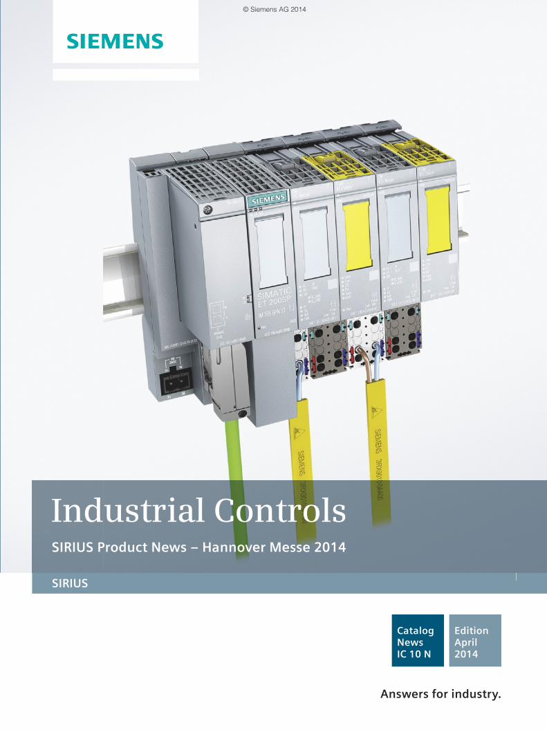
SIRIUS Industrial Controls SIRIUS Product News ‒ Hannover Messe 2014 Answers for industry. Catalog News IC 10 N Edition April 2014 © Siemens AG 2014
Transcript of Catalog News IC 10 N · 04/2014 - Siemens Global Website · Catalog News IC 10 N Edition April ......
SIRIUS
Industrial ControlsSIRIUS Product News ‒ Hannover Messe 2014
Answers for industry.
CatalogNews IC 10 N
Edition April2014
umschlag_IC10N_04_2014_EN.indd 3umschlag_IC10N_04_2014_EN.indd 3 21.05.2014 10:43:1921.05.2014 10:43:19
© Siemens AG 2014

Related catalogs Miscellaneous
Trademarks Technical Assistance
Industrial Controls IC 10SIRIUS
E86060-K1010-A101-A4-7600
Industrial Controls IC 10 AOSIRIUS 3R_1*in sizes S00/S0 to S12
PDF/E-book (E86060-K1010-A191-A3-7600)
Low-Voltage Power Distribution and LV 10Electrical Installation Technology SENTRON · SIVACON · ALPHAProtection, Switching, Measuring and Monitoring Devices, Switchboards and Distribution Systems
E86060-K8280-A101-A1-7600
Safety Integrated SI 10Safety Technology forFactory Automation
E86060-K7010-A101-A3-7600
Industrial Communication IK PISIMATIC NET
E86060-K6710-A101-B7-7600
SIMATIC ST 70Products forTotally Integrated Automation
E86060-K4670-A101-B4-7600
SIMOTICS Low-Voltage Motors D 81.1Type series 1LE1, 1MB1 and 1PC1Frame sizes 80 to 315Power range 0.3 to 250 kW
E86060-K5581-A111-A6-7600
SITRAIN ITCTraining for Industry
Only available in GermanE86060-K6850-A101-C4
Products for Automation and Drives CA 01Interactive Catalog, DVD
E86060-D4001-A510-D3-7600
Industry MallInformation and Ordering Platformin the Internet:
www.siemens.com/industrymall
Information and Download CenterDigital versions of the catalogs are available in the Internet
www.siemens.com/sirius/catalogs
Response E-mailPlease send your comments and suggestions for improvement [email protected] (include the catalog name in the subject field)
Registered trademarksAll product designations may be registered trademarks or product names of Siemens AG or other supplying companies. Third parties using these trademarks or product names for their own purposes may infringe upon the rights of the trademark owners.
Further information about industrial controls:www.siemens.com/sirius
Technical AssistanceExpert technical assistance for Industrial controls:Tel.: +49 (911) 895-5900Fax: +49 (911) 895-5907
E-Mail: [email protected]
U2_IC10N_04_2014_en.fm Seite 1 Dienstag, 20. Mai 2014 3:45 15
© Siemens AG 2014

SIRIUSIndustrial Controls
Catalog IC 10 N · 04/2014
Supersedes:Catalog News IC 10 N up to 03/2014
Refer to the Industry Mall for current updates of this catalog:www.siemens.com/industrymall
Please contact your local Siemens branch
© Siemens AG 2014
The products and sys-tems described in this catalog are manufac-tured/distributed under application of a certified quality management system in accordance with EN ISO 9001 (for the Certified Registration Nos. see www.siemens.com/sys-tem-certificates/ce). The certificate is recognized by all IQNet countries.
1 Introduction
2 Industrial Communication
3 Switching Devices – Contactors and Contactor Assemblies –for Switching Motors
4 Switching Devices – Contactors and Contactor Assemblies –Special Applications
5 Switching Devices – Contactors and Contactor Assemblies –Contactor Relays and Relays
6 Switching Devices – Soft Starters and Solid-State Switching Devices
7 Protection Equipment
8 Load Feeders and Motor Starters for Use in the Control Cabinet
9 Motor Starters for Use in the Field, High Degree of Protection
10 Monitoring and Control Devices
11 Safety Technology
12 Position and Safety Switches
13 Commanding and Signaling Devices
14 Parametrization, Configuration and Visualization with SIRIUS
15 Products for Specific Requirements
16 Appendix
IC10_00_Vorspann.book Seite 1 Donnerstag, 15. Mai 2014 12:26 12
© Siemens AG 2014
2 Siemens IC 10 N · 04/2014
Product News
AS-Interface AS-Interface software
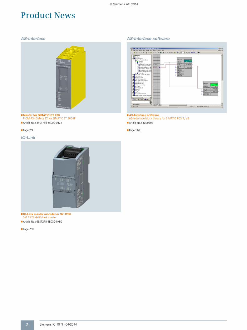
Master for SIMATIC ET 200 F-CM AS-i Safety ST for SIMATIC ET 200SP
Article No.: 3RK1736-6SC00-0BC1
Page 2/9
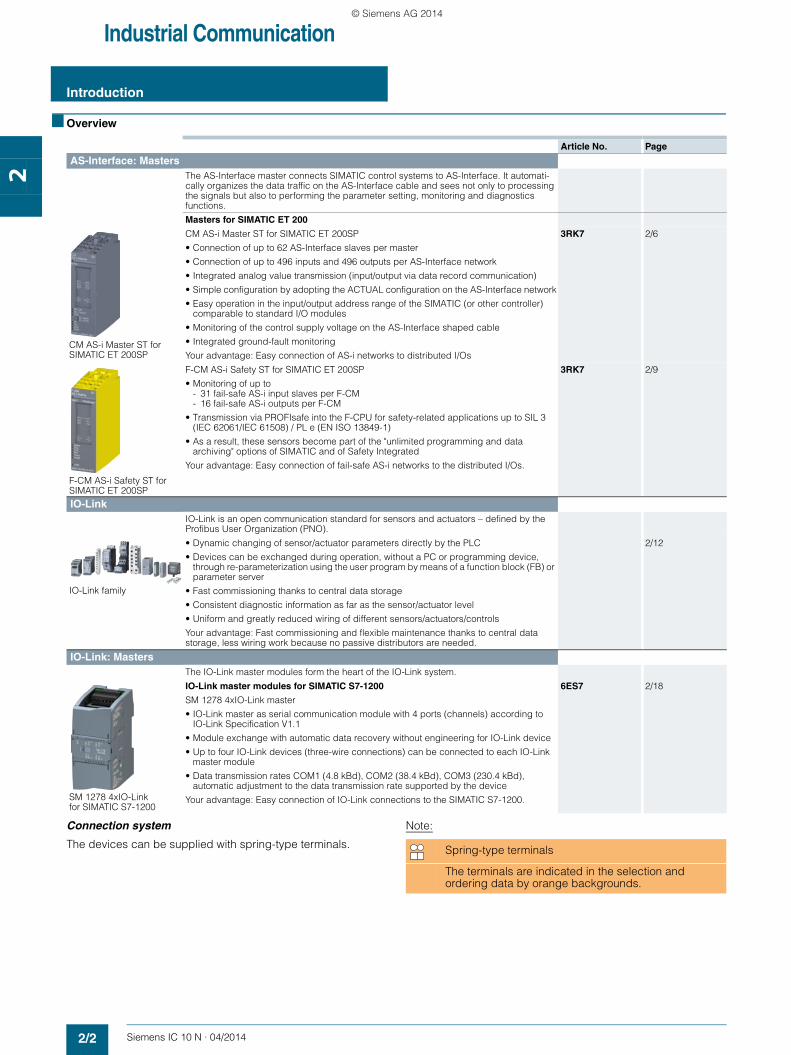
AS-Interface softwareAS-Interface block library for SIMATIC PCS 7, V8
Article No.: 3ZS1635
Page 14/2
IO-Link
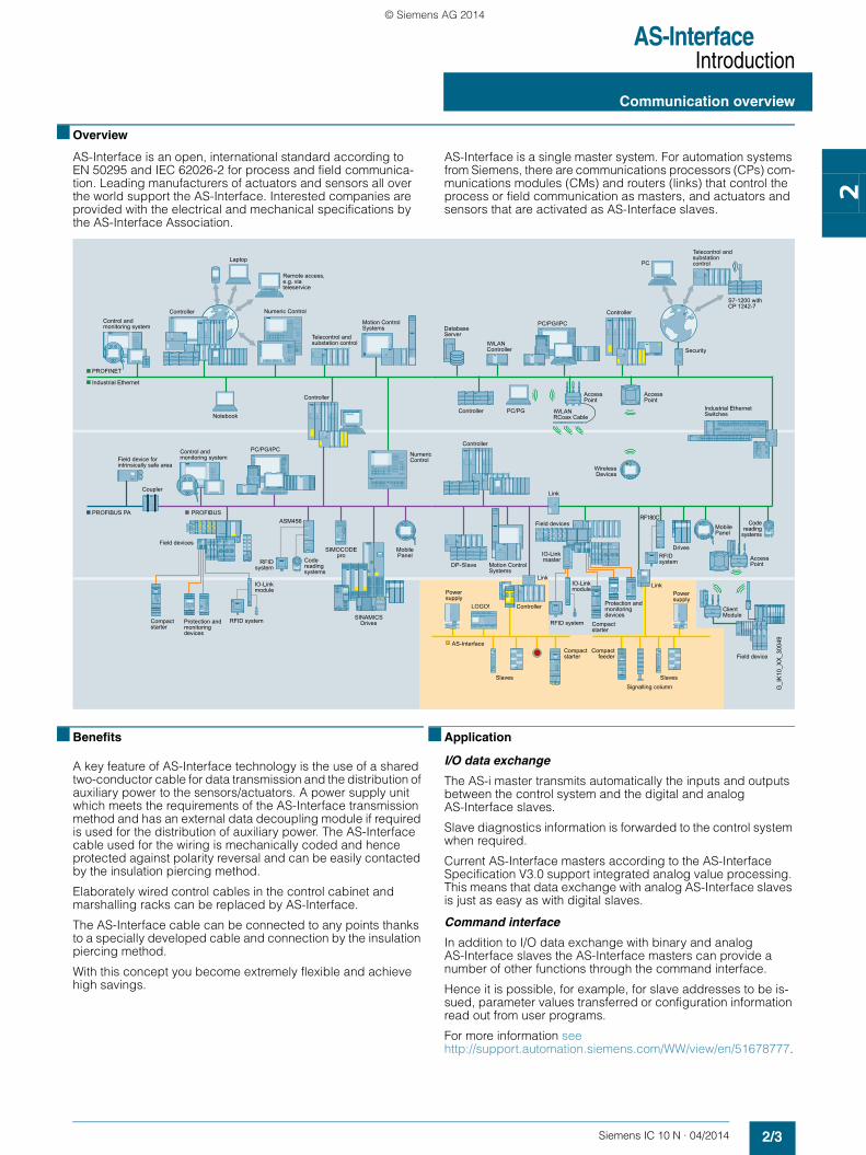
IO-Link master module for S7-1200SM 1278 4xIO-Link master
Article No.: 6ES7278-4BD32-0XB0
Page 2/18
IC10_00_Vorspann.book Seite 2 Donnerstag, 15. Mai 2014 12:26 12
© Siemens AG 2014

Siemens IC 10 N · 04/2014
2
Siemens IC 10 N · 04/2014
2
Price groupsPG 212, 255, 256, 42C
2/2 Introduction
AS-Interface
Introduction2/3 Communication overview2/4 System components2/5 AS-Interface Specification
- Specification V3.0
Masters
Masters for SIMATIC ET 2002/6 - CM AS-i Master ST for
SIMATIC ET 200SP2/9 - F-CM AS-i Safety ST for
SIMATIC ET 200SP
IO-Link
Introduction2/12 Communication overview2/13 System components2/17 IO-Link Specification
Masters
IO-Link master module for S7-12002/18 - SM 1278 4xIO-Link master
Industrial Communication
SIRIUS_IC10N_chap02_English_2014.book Seite 1 Dienstag, 20. Mai 2014 3:51 15
© Siemens AG 2014
Industrial Communication
Introduction
2/2 Siemens IC 10 N · 04/2014
2
■ Overview
Connection system
The devices can be supplied with spring-type terminals.
Note:
Article No. Page
AS-Interface: MastersThe AS-Interface master connects SIMATIC control systems to AS-Interface. It automati-cally organizes the data traffic on the AS-Interface cable and sees not only to processing the signals but also to performing the parameter setting, monitoring and diagnostics functions.
Masters for SIMATIC ET 200
CM AS-i Master ST for SIMATIC ET 200SP
CM AS-i Master ST for SIMATIC ET 200SP
• Connection of up to 62 AS-Interface slaves per master
• Connection of up to 496 inputs and 496 outputs per AS-Interface network
• Integrated analog value transmission (input/output via data record communication)
• Simple configuration by adopting the ACTUAL configuration on the AS-Interface network
• Easy operation in the input/output address range of the SIMATIC (or other controller) comparable to standard I/O modules
• Monitoring of the control supply voltage on the AS-Interface shaped cable
• Integrated ground-fault monitoring
Your advantage: Easy connection of AS-i networks to distributed I/Os
3RK7 2/6
F-CM AS-i Safety ST for SIMATIC ET 200SP
F-CM AS-i Safety ST for SIMATIC ET 200SP
• Monitoring of up to - 31 fail-safe AS-i input slaves per F-CM- 16 fail-safe AS-i outputs per F-CM
• Transmission via PROFIsafe into the F-CPU for safety-related applications up to SIL 3 (IEC 62061/IEC 61508) / PL e (EN ISO 13849-1)
• As a result, these sensors become part of the "unlimited programming and data archiving" options of SIMATIC and of Safety Integrated
Your advantage: Easy connection of fail-safe AS-i networks to the distributed I/Os.
3RK7 2/9
IO-Link IO-Link is an open communication standard for sensors and actuators – defined by the Profibus User Organization (PNO).
IO-Link family
• Dynamic changing of sensor/actuator parameters directly by the PLC
• Devices can be exchanged during operation, without a PC or programming device, through re-parameterization using the user program by means of a function block (FB) or parameter server
• Fast commissioning thanks to central data storage
• Consistent diagnostic information as far as the sensor/actuator level
• Uniform and greatly reduced wiring of different sensors/actuators/controls
Your advantage: Fast commissioning and flexible maintenance thanks to central data storage, less wiring work because no passive distributors are needed.
2/12
IO-Link: MastersThe IO-Link master modules form the heart of the IO-Link system.
SM 1278 4xIO-Linkfor SIMATIC S7-1200
IO-Link master modules for SIMATIC S7-1200
SM 1278 4xIO-Link master
• IO-Link master as serial communication module with 4 ports (channels) according to IO-Link Specification V1.1
• Module exchange with automatic data recovery without engineering for IO-Link device
• Up to four IO-Link devices (three-wire connections) can be connected to each IO-Link master module
• Data transmission rates COM1 (4.8 kBd), COM2 (38.4 kBd), COM3 (230.4 kBd), automatic adjustment to the data transmission rate supported by the device
Your advantage: Easy connection of IO-Link connections to the SIMATIC S7-1200.
6ES7 2/18
Spring-type terminals
The terminals are indicated in the selection and ordering data by orange backgrounds.
SIRIUS_IC10N_chap02_English_2014.book Seite 2 Dienstag, 20. Mai 2014 3:51 15
© Siemens AG 2014
AS-InterfaceIntroduction
2/3Siemens IC 10 N · 04/2014
Communication overview
2
■ Overview
AS-Interface is an open, international standard according to EN 50295 and IEC 62026-2 for process and field communica-tion. Leading manufacturers of actuators and sensors all over the world support the AS-Interface. Interested companies are provided with the electrical and mechanical specifications by the AS-Interface Association.
AS-Interface is a single master system. For automation systems from Siemens, there are communications processors (CPs) com-munications modules (CMs) and routers (links) that control the process or field communication as masters, and actuators and sensors that are activated as AS-Interface slaves.
■ Benefits
A key feature of AS-Interface technology is the use of a shared two-conductor cable for data transmission and the distribution of auxiliary power to the sensors/actuators. A power supply unit which meets the requirements of the AS-Interface transmission method and has an external data decoupling module if required is used for the distribution of auxiliary power. The AS-Interface cable used for the wiring is mechanically coded and hence protected against polarity reversal and can be easily contacted by the insulation piercing method.
Elaborately wired control cables in the control cabinet and marshalling racks can be replaced by AS-Interface.
The AS-Interface cable can be connected to any points thanks to a specially developed cable and connection by the insulation piercing method.
With this concept you become extremely flexible and achieve high savings.
■ Application
I/O data exchange
The AS-i master transmits automatically the inputs and outputs between the control system and the digital and analog AS-Interface slaves.
Slave diagnostics information is forwarded to the control system when required.
Current AS-Interface masters according to the AS-Interface Specification V3.0 support integrated analog value processing. This means that data exchange with analog AS-Interface slaves is just as easy as with digital slaves.
Command interface
In addition to I/O data exchange with binary and analog AS-Interface slaves the AS-Interface masters can provide a number of other functions through the command interface.
Hence it is possible, for example, for slave addresses to be is-sued, parameter values transferred or configuration information read out from user programs.
For more information seehttp://support.automation.siemens.com/WW/view/en/51678777.
Control andmonitoring system
Telecontrol and substation control
Remote access, e.g. via teleservice
Control andmonitoring systemField device for
intrinsically safe area
Coupler
Field devices
Code reading systems
RFID system
Telecontrol and substation control
S7-1200 withCP 1242-7
Compactstarter
Compactstarter
Compactfeeder
Field devices
Field device
Power supply
Signalling column
Powersupply
Code reading
systems
IO-Linkmaster RFID
system
Compactstarter
Protection and monitoring devices
Protection and monitoring devices
IO-Link module
IO-Link module
RFID system RFID system
PC/PG/IPC
Controller
Industrial Ethernet
PROFIBUSPROFIBUS PA
Laptop
Motion ControlSystems
Notebook
SINAMICS Drives
Numeric Control
MobilePanel
SIMOCODE pro
PROFINET
ASM456
Controller
PC/PG/IPC
Controller
Security
Link
Drives
PC/PG
Mobile Panel
IWLAN Controller
Database Server
DP-Slave Motion ControlSystems
ControllerLOGO!
Slaves Slaves
AS-Interface
Link
RF180C
AccessPoint
Link
Industrial EthernetSwitchesIWLAN
RCoax Cable
G_I
K10
_XX
_300
49
Controller Numeric Control
Controller
AccessPoint
ClientModule
PC
Wireless Devices
AccessPoint
SIRIUS_IC10N_chap02_English_2014.book Seite 3 Dienstag, 20. Mai 2014 3:51 15
© Siemens AG 2014

AS-InterfaceIntroduction
System components
2/4 Siemens IC 10 N · 04/2014
2
■ Overview
To implement communication, a system installation has the following main components: • Master interface modules for central control units such as
SIMATIC S7, ET 200M/ET 200SP distributed peripherals, or routers from PROFIBUS/PROFINET to AS-Interface
• Power supply units, if required in combination with a data decoupling module for the power supply to the slaves
• AS-Interface shaped cables
• Network components such as repeaters and extension plugs (cannot be used for AS-i Power24V)
• Modules for connection of standard sensors/actuators• Actuators and sensors with integrated AS-i slave• Safety modules for transmitting safety-related data through
AS-Interface• Addressing units for setting the slave addresses during
commissioning
Example of a configuration with the system components
Features
24 V DCpower supply
AS-Interfacepower supply
AS-Interfacepower supply
Digital and analog K20, K45, K60 field modules
3RA2 load feeders
3RA6 compact starters
SIRIUS M200D motor starters or G110D inverters
Load feeders with safe AS-i outputs
Safe EMERGENCY-STOP and field module
Signaling columns
Pushbuttons Indicator lights
Safe and standard control cabinet modules S22.5 and S45
S7-1200 with CM 1243-2
CM AS-i Master ST for ET 200SP
S7-300CP343-2(P)
MSS ASIsafe
MSS Advanced
S7-200with CP 243-2
Safety switch withouttumbler
withtumbler
SIMATIC/SIMOTION
PROFINET
AS-Interface
Industrial EthernetPROFIBUS DP
G_I
K10
_XX
_200
27j
SINUMERIK
S7-300CP 343-2(P)
DP/AS-i LINK Advanced
IE/AS-i LINK PN IO
DP/AS-i F-Link
DP/AS-i Link 20E
Standard EN 50295 / IEC 62026-2
Topology Line, star or tree structure (same as electrical wiring)
Transmission medium Unshielded two-wire cable (2 x 1.5 mm2) for data and auxiliary power
Connection system Contacting of the AS-Interface cable by insulation piercing method
Maximum cable length • 100 m without repeater• 200 m with extension plug • 300 m with two repeaters in series connection• 600 m with extension plugs and two repeaters
parallel switched Longer cable lengths also possible through parallel switching of more repeaters
Maximum cycle time • 5 ms in full expansion with 31 standard addresses
• 10 ms in full expansion with 62 A/B addresses• Profile-specific for slaves with expanded data,
e.g. analog slaves
Number of stations per AS-Interface line
• Up to 62 slaves (A/B technology) • Integrated analog value transmission
Number of binary sensors and actuators
Max. 496 DI/496 DO
Access control • Cyclic polling master/slave procedure• Cyclic data acceptance from host (PLC, PC)
Error safeguard Identification and repetition of faulty message frames
SIRIUS_IC10N_chap02_English_2014.book Seite 4 Dienstag, 20. Mai 2014 3:51 15
© Siemens AG 2014

AS-InterfaceIntroduction
2/5Siemens IC 10 N · 04/2014
AS-Interface SpecificationSpecification V3.0
2
■ Overview
Scope of AS-Interface Specification V3.0
Basic data• AS-Interface Specification V3.0 describes a fieldbus system
with an AS-i master and up to 62 AS-i slaves. • The standard slaves continue to occupy one AS-i address
(1...31). • Slaves with extended addressing divide an address into
an A address (1A...31A) and a B address (1B...31B). Up to 62 A/B slaves can be connected accordingly to one AS-Interface network.
• Mixed operation of standard slaves and A/B slaves is possible without difficulty. The AS-i master identifies automatically which type of slave is connected. No special adjustments are required of the user.
• One digital AS-i slave has up to 4 digital inputs and 4 digital outputs.
• Transmission of the digital input/output data requires max. 5 ms cycle time for 31 slaves; for further values see "Communication cycle".
• The integrated analog value transmission function enables access to both analog values and digital values, without the need for any special function blocks.
Communication cycle
Each address is queried in max. 5 ms cycle time. If two A/B slaves are operated on one basic address (e.g. 12A and 12B), a maximum 10 ms will be required for updating the data of both slaves.
All slave types can be mixed and used on a single AS-Interface network.
More information, e.g. whether an AS-Interface slave is a stan-dard slave or an A/B slave, see the selection and ordering data in Catalog IC 10, chapter 2 "Industrial Communication" "AS-Interface".
Available masters with current AS-Interface Specification V3.0• CP 343-2, CP 343-2P (S7-300 / ET 200M)• DP/AS-i LINK Advanced• DP/AS-i F-Link• DP/AS-Interface Link 20E• IE/AS-i LINK PN IO• CM 1243-2 (S7-1200)• CM AS-i Master ST (ET 200SP)
■ More information
AS-Interface system manual
The "AS-Interface" system manual can be downloaded free from the Internet.• German
http://support.automation.siemens.com/WW/view/de/26250840• English
http://support.automation.siemens.com/WW/view/en/26250840
Maximum number of slaves
Number of digital inputs
Number of digital outputs
Digital Analog ASIsafe DI DO
62 62 31 62 8 = 496 62 8 = 496
Maximum cycle time (digital signals)
• 5 ms for 31 slaves• 10 ms for 62 slaves• Up to 20 ms for A/B slaves with 4DI/4DO• Up to 40 ms for A/B slaves with 8DI/8DO
SIRIUS_IC10N_chap02_English_2014.book Seite 5 Dienstag, 20. Mai 2014 3:51 15
© Siemens AG 2014

AS-InterfaceMastersMasters for SIMATIC ET 200CM AS-i Master ST for SIMATIC ET 200SP
2/6 Siemens IC 10 N · 04/2014
2
■ Overview
CM AS-i Master ST for SIMATIC ET 200SP
The CM AS-i Master ST communication module is designed for use in the SIMATIC ET 200SP distributed I/O system and has the following features:• Connection of up to 62 AS-Interface slaves• Support for all AS-Interface master functions according to
AS-Interface Specification V3.0• User-friendly configuration with graphic display of the AS-i line
in TIA Portal V12.0 or in other systems by using GSD• Supply via AS-Interface cable• Suitable for AS-i Power24V and for AS-Interface with
30 V voltage• Integrated ground-fault monitoring for the AS-Interface cable• Through connection to AS-Interface, the number of digital in-
puts and outputs available for the control system is greatly in-creased (max. 496 DI/496 DO on the AS-Interface per CM AS-i Master ST).
• Integrated analog value processing (all analog profiles)
Basic unit: ET 200SP distributed I/O system
SIMATIC ET 200SP is a scalable and highly flexible distributed I/O system for connecting the process signals to a central control system via PROFIBUS or PROFINET.
Up to eight CM AS-i Master STs can be plugged into a SIMATIC ET 200SP with the IM 155-6 PN standard interface module.
More information see the system manual "SIMATIC ET 200SP Distributed I/O System ET 200SP", http://support.automation.siemens.com/WW/view/en/58649293.
DesignThe CM AS-i Master ST module features a 20 mm wide ET 200SP module housing. A C0 type BaseUnit (BU) is required for use in the ET 200SP. The module has LED indicators for diagnostics, operation, AS-i voltage and AS-i slave status and offers informative front-side module inscription for• Plain-text marking of the module type and function class• 2D matrix code (Article No. and serial number)• Circuit diagram• Color coding of the CM module type: light gray• Hardware and firmware version• Complete Article No.
FunctionThe CM AS-i Master ST supports all specified functions of the AS-Interface Specification V3.0.The input/output values of the digital AS-i slaves can be acti-vated via the cyclic process image. The values of the analog AS-i slaves can be reached via data record transfer.If required, master calls can be performed with the command interface, e.g. read/write parameters, read/write configuration.Changeover of the operating mode, automatic application of the slave configuration and re-addressing of a connected AS-i slave can be implemented via the control panel of the CM AS-i Master ST in the TIA Portal.
Safety note
The use of this product requires suitable protective measures (e.g. network segmentation for IT security among others) in order to ensure safe plant operation, see www.siemens.com/industrialsecurity.
Configuration
The following software is required for configuration of the CM AS-i Master ST module:• STEP 7 (classic), V5.5 SP3 HF4 or higher with HSP 2092 or• STEP 7 (TIA Portal), V12 or higher or• the GSD file of the ET 200SP with STEP 7 or another
engineering toolThe TIA Portal enables user-friendly configuration and diagnos-tics of the AS-i master and, in the event of interfacing to a SIMATIC S7-300/S7-400 station, any connected slaves.
Alternatively, you can also apply the AS-Interface ACTUAL con-figuration as the DESIRED configuration at the "touch of a button" via the control panel integrated in the TIA Portal or connection of an optional button. Configuration with the GSD file is possible only with the button.
Configuration of an AS-Interface network with CM AS-i Master ST via TIA Portal
The CM AS-i Master ST module occupies 32 input bytes and 32 output bytes in the I/O data of the ET 200SP station.
SIRIUS_IC10N_chap02_English_2014.book Seite 6 Dienstag, 20. Mai 2014 3:51 15
© Siemens AG 2014

AS-InterfaceMasters
Masters for SIMATIC ET 200CM AS-i Master ST for SIMATIC ET 200SP
2/7Siemens IC 10 N · 04/2014* You can order this quantity or a multiple thereof.Illustrations are approximate
2
■ Benefits
The CM AS-i Master ST for ET 200SP communication module enables modular, simple and high-performance expansion of AS-Interface networks via engineering in the TIA Portal.
Up to eight CM AS-i Master ST units can be plugged into one ET 200SP station with IM 155-6 PN Standard. The maximum configuration depends on the interface module used.
Multiple masters as well as single masters can thus be imple-mented in the ET 200SP depending on the number of modules.
Together with the interface module, a scalable PROFINET/AS-i Link or PROFIBUS/AS-i Link can be assembled.
■ Application
Configuration examples of AS-Interface networks with CM AS-i Master ST for SIMATIC ET 200SP
Configuration of AS-Interface networks under a SIMATIC ET 200SP
■ Selection and ordering data
■ Accessories
Version DT Article No. Priceper PU
PU(UNIT,
SET, M)
PS* PG
3RK7137-6SA00-0BC1
CM AS-i Master ST communication module A 3RK7137-6SA00-0BC1 1 1 unit 42C
• AS-Interface master for SIMATIC ET 200SP, can be plugged onto BaseUnit type C0
• Corresponds to AS-Interface Specification V3.0
• Dimensions (W H D / mm): 20 x 73 x 58
Version DT Spring-type terminals PU(UNIT,
SET, M)
PS* PG
Article No. Priceper PU
6ES7193-6BP20-0DC0
BaseUnit BU20-P6+A2+4D
• BaseUnit (light), BU type C0
• Suitable for the CM AS-i Master ST module
• For connection of AS-Interface cable to CM AS-i Master ST
• Beginning of an AS-i network, separation of the AS-i voltage to the left module
A 6ES7193-6BP20-0DC0 1 1 unit 255
Controllere. g. S7-1500
SIMATIC ET 200SPwith 2 x CM AS-i masters ST
SIMATIC ET 200SPwith CM AS-i master ST
Pushbuttons and indicator lights
Field module
3RA6 compact starter
M200D motor starter
Signal columns
Pushbuttons and indicator lights
Field module
3RA6 compact starter
M200D motor starter
Signal columns
IC01
_002
37a
PROFINET
AS-InterfaceAS-InterfaceAS-Interface
PROFIBUS
SIRIUS_IC10N_chap02_English_2014.book Seite 7 Dienstag, 20. Mai 2014 3:51 15
© Siemens AG 2014

AS-InterfaceMastersMasters for SIMATIC ET 200CM AS-i Master ST for SIMATIC ET 200SP
2/8 Siemens IC 10 N · 04/2014* You can order this quantity or a multiple thereof.
Illustrations are approximate
2
■ More information
Manuals
Manual "CM AS-i Master ST for SIMATIC ET 200SP" see http://support.automation.siemens.com/WW/view/en/71756485.
Manual "SIMATIC ET 200SP BaseUnits" see http://support.automation.siemens.com/WW/view/en/59753521.
System manual "SIMATIC ET 200SP Distributed I/O System ET 200SP" see http://support.automation.siemens.com/WW/view/en/58649293.
Industry Mall
More information see Industry Mall at "Automation Technology" ➞ "Industrial Communication" ➞ "AS-Interface" ➞ "Masters" ➞ "Masters for SIMATIC ET 200".
Version DT Article No. Priceper PU
PU(UNIT,
SET, M)
PS* PG
6ES7155-6AA00-0BN0
PROFINET interface modules IM 155-6 PN Standard Max. 32 I/O modules, max. 256 bytes of I/O data per station
• Including server module and bus adapter 2 x RJ45 (delivered without RJ45 plug)
A 6ES7155-6AA00-0BN0 1 1 unit 255
• Including server module (bus adapter must be ordered separately, see below)
A 6ES7155-6AU00-0BN0 1 1 unit 255
PROFINET interface module IM 155-6 PN High FeatureMax. 64 I/O modules, max. 1440 bytes of I/O data per station
• Including server module (bus adapter must be ordered separately, see below)
A 6ES7155-6AU00-0CN0 1 1 unit 255
PROFIBUS interface module IM 155-6 DP High Feature Max. 32 I/O modules, max. 244 bytes of I/O data per station
• Including server module and PROFIBUS connector A 6ES7155-6BA00-0CN0 1 1 unit 255
Bus adapter for PROFINET For connection of the Ethernet cable to the PROFINET IM 155-6 PN interface module
6ES7193-6AR00-0AA0
• Connection 2 x RJ45 (delivered without RJ45 plug) A 6ES7193-6AR00-0AA0 1 1 unit 255
6ES7193-6AF00-0AA0
• Connection 2 x FC (FastConnect) A 6ES7193-6AF00-0AA0 1 1 unit 255
SIRIUS_IC10N_chap02_English_2014.book Seite 8 Dienstag, 20. Mai 2014 3:51 15
© Siemens AG 2014

AS-InterfaceMasters
2/9Siemens IC 10 N · 04/2014
Masters for SIMATIC ET 200F-CM AS-i Safety ST for SIMATIC ET 200SP
2
■ Overview
F-CM AS-i Safety ST for SIMATIC ET 200SP
The F-CM AS-i Safety ST fail-safe communication module supplements an AS-Interface network without additional wiring to produce a safety-related AS-i network.
Important features:• Fail-safe communication module for the ET 200SP
- 31 fail-safe input channels in the process image- 16 fail-safe output channels in the process image- Certified up to SIL 3 (IEC 62061/IEC 61508),
PL e (EN ISO 13849-1) - Parameterization conforms with other fail-safe I/O modules
of the ET 200SP• The communication module supports PROFIsafe in
PROFINET configurations. Suitable for use with fail-safe SIMATIC S7-300F/S7-416F CPUs.
• For reading up to 31 fail-safe AS-i input slaves- 2 sensor inputs/signals for each fail-safe AS-i input slave - Adjustable evaluation of sensor signals: 2-channel or
2 x 1-channel- Integrated discrepancy evaluation in the case of 2-channel
signals- Integrated AND operation in the case of 2 x 1-channel
signals- Input delay can be parameterized- Start-up test can be set- Sequence monitoring can be activated
• For control of up to 16 fail-safe AS-i output circuit groups- The output circuit groups are controlled independently of
one another. - One output circuit group can act on one or more actuators
(e.g. to switch drives simultaneously).- An actuator (e.g. a contactor) is interfaced via a fail-safe
AS-i output module (e.g. safe SlimLine module S45F, Article No. 3RK1405-1SE15-0AA2; see Catalog IC 10, chapter 2 "Industrial communication" "ASIsafe" "Fail-safe AS-Interface modules").
- Simple fault acknowledgment via the process image• Simple module replacement thanks to automatic importing of
the safety parameters from the coding element• Comprehensive diagnostic options• Can be plugged onto type C1 or type C0 BaseUnits (BU)• Supply via AS-Interface voltage• 8 LED indicators for diagnostics, operating state, fault
indication and supply voltage
• Informative front-side module inscription- Plain-text marking of the module type and function class- 2D matrix code (Article No. and serial number)- Circuit diagram- Color coding of the CM module type: light gray- Hardware and firmware version- Complete Article No.
• Optional labeling accessories- Labeling strips- Reference identification label
Design
The fail-safe F-CM AS-i Safety ST module has an ET 200SP module enclosure with a width of 20 mm.
One AS-i master according to the AS-i Specification V3.0 and fail-safe AS-i input slaves and/or fail-safe AS-i output modules are needed for operation. The CM AS-i Master ST communica-tion module (Article No. 3RK7137-6SA00-0BC1) is recom-mended as the AS-i master for the ET 200SP, see page 2/7.
SIMATIC AS-i F-Link
Simple combination of the CM AS-i Master ST and F-CM AS-i Safety ST modules in one ET 200SP station with PROFINET interfacing results in a powerful PN/AS-i F-Link, which can be expanded further in a modular fashion.
SIMATIC AS-i F-Link: Combination of an ET 200SP interface module, CM AS-i Master ST and F-CM AS-i Safety ST
With the digital and analog I/O modules of the ET 200SP, local inputs and outputs can be realized in the SIMATIC AS-i F-Link so as to ensure that the F-Link complies precisely with customer requirements. Expansion variants for almost every application are possible thanks to the selection of standard and fail-safe I/O modules.
Besides the single AS-i master, double, triple or generally multi-ple masters can be realized with or without fail-safe functionality.
Supported BaseUnits
With the recommended combination of the CM AS-i Master ST and F-CM AS-i Safety ST modules, the CM module is plugged onto a light type C0 BaseUnit and, directly on the right of it, the F-CM module is plugged onto a dark type C1 BaseUnit. The AS-i cable is connected only on the light BaseUnit of the CM module.
If the F-CM AS-i Safety ST module is not combined with the CM AS-i Master ST module, but another AS-i master is used instead, then the F-CM module is plugged onto a light type C0 BaseUnit. In this case, the AS-i cable is connected on the light BaseUnit of the F-CM module.
SIRIUS_IC10N_chap02_English_2014.book Seite 9 Dienstag, 20. Mai 2014 3:51 15
© Siemens AG 2014

AS-InterfaceMastersMasters for SIMATIC ET 200F-CM AS-i Safety ST for SIMATIC ET 200SP
2/10 Siemens IC 10 N · 04/2014
2
Safety note:
The use of this product requires suitable protective measures (e.g. network segmentation for IT security among others) in order to ensure safe plant operation, see www.siemens.com/industrialsecurity.
Configuration
The following software is required for configuration of the F-CM AS-i Safety ST module:• STEP 7 (classic), V5.5 SP3 HF4 or higher with HSP 2093 and
Distributed Safety V5.4 SP5 or F-Configuration Pack SP11
Configuration and programming are done entirely in the STEP 7 user interface. No additional configuration software is needed for commissioning.
Data management – together with all other configuration data of the SIMATIC – is realized completely in the S7 project.
The input and output channels are assigned to the process im-age automatically and manual linking via configuration function blocks is not necessary.
If the F-CM AS-i Safety ST module is replaced, all necessary settings are automatically imported into the new module.
The F-CM AS-i Safety ST module occupies 16 input bytes and 8 output bytes in the I/O data of the ET 200SP station.
■ Application
Thanks to use of the fail-safe module in the ET 200SP, it is possi-ble to fulfill the safety-related application requirements in a manner that is integrated in the overall automation solution.
The safety functions required for fail-safe operation are inte-grated in the modules. Communication with the fail-safe SIMATIC S7 CPUs is realized via PROFIsafe.
The safety application is programmed in the SIMATIC S7 F-CPU with Distributed Safety. The fail-safe input signals of the ASIsafe slave modules are read via the AS-i bus line and are combined with any chosen further signals in the fail-safe program.
The fail-safe output signals can be output through fail-safe SIMATIC output modules or also directly via AS-i – with the aid of fail-safe AS-i output modules, e.g. 3RK1405-1SE15-0AA2 (see Catalog IC 10, chapter 2 "Industrial Communication" "ASIsafe" "Fail-safe AS-Interface modules"). No special functions are required for this in the program.
Configuration examples of AS-Interface networks with CM AS-i Master ST and F-CM AS-i Safety ST for SIMATIC ET 200SP
AS-Interface configuration with SIMATIC AS-i F-Link, consisting of an ET 200SP station with CM AS-i Master ST and F-CM AS-i Safety ST modules
Safety-orientedprocessing
Operationalcontrol
Safe controlSIMATIC S7-300F
Safe position switch with door interlock
Field module
Load feeder with safe AS-i outputs
Digital K45 field module
3RA2 load feeder
Safe EMERGENCY-STOP
IC01
_002
88AS-Interface / ASIsafe
PROFINET / PROFIsafe
SIMATIC AS-i F-Link
SIMATIC AS-i F-Link
3
4
5
6
1
2
3 4 5 61 2 3 4 5 61 2 3 4 5 61 2
AS-Interface / ASIsafeAS-Interface / ASIsafe
SIRIUS_IC10N_chap02_English_2014.book Seite 10 Dienstag, 20. Mai 2014 3:51 15
© Siemens AG 2014

AS-InterfaceMasters
Masters for SIMATIC ET 200F-CM AS-i Safety ST for SIMATIC ET 200SP
2/11Siemens IC 10 N · 04/2014* You can order this quantity or a multiple thereof.Illustrations are approximate
2
■ Selection and ordering data
■ Accessories
More accessories see page 2/8.
■ More information
Manuals
Manual "F-CM AS-i Safety ST Module for SIMATIC ET 200SP" see http://support.automation.siemens.com/WW/view/en/90265988.
Manual "SIMATIC ET 200SP BaseUnits" see http://support.automation.siemens.com/WW/view/en/59753521.
System manual "SIMATIC ET 200SP Distributed I/O System ET 200SP" see http://support.automation.siemens.com/WW/view/en/58649293.
Industry Mall
More information see Industry Mall at "Automation Technology" ➞ "Industrial Communication" ➞ "AS-Interface" ➞ "Masters" ➞ "Masters for SIMATIC ET 200".
Version DT Article No. Priceper PU
PU(UNIT,
SET, M)
PS* PG
3RK7136-6SC00-0BC1
F-CM AS-i Safety ST communication module A 3RK7136-6SC00-0BC1 1 1 unit 42C
• Fail-safe module for SIMATIC ET 200SP, can be plugged onto BaseUnit type C1 (alternatively type C0)
• Operation requires an AS-i master, e.g. CM AS-i Master ST (see page 2/7).
• Can be used up to SIL 3 (IEC 62061/IEC 61508), PL e (EN ISO 13849-1)
• Approved for use with the PROFINET interface modules IM 155-6 PN Standard and IM 155-6 PN High Feature, under CPU S7-300F or CPU S7-416F. More approvals on request.
• Coding element type F (included in scope of supply)
• Dimensions (W H D / mm): 20 x 73 x 58
Version DT Spring-type terminals PU(UNIT,
SET, M)
PS* PG
Article No. Priceper PU
6ES7193-6BP20-0BC1
BaseUnit BU20-P6+A2+4B
• BaseUnit (dark), BU type C1
• Suitable for the F-CM AS-i Safety ST fail-safe module
• Continuation of an AS-i network, connection to the AS-i voltage of the left module
A 6ES7193-6BP20-0BC1 1 1 unit 255
Coding element type F (spare part)
• For the ET 200SP modules F-CM AS-i Safety ST, F-DI, F-DQ, F-PM-E
• Packaging unit of 5 units
A 6ES7193-6EF00-1AA0 1 5 units 256
SIRIUS_IC10N_chap02_English_2014.book Seite 11 Dienstag, 20. Mai 2014 3:51 15
© Siemens AG 2014

IO-LinkIntroduction
Communication overview
2/12 Siemens IC 10 N · 04/2014
2
■ Overview
IO-Link is an open communication standard for sensors and actuators – defined by the Profibus User Organization (PNO). IO-Link technology is based on the point-to-point connection of sensors and actuators to the control system.
Parameter and diagnostics data are transmitted in addition to the cyclic operating data for the connected sensors/actuators. The simple, unshielded three-wire cable customary for standard sensors is used for this purpose.
■ Benefits
Engineering• Standardized, open system for greater flexibility (non-Siemens
IO-Link devices can be integrated in engineering)• Uniform, transparent configuring and programming through
integrated engineering (SIMATIC STEP 7)• Unassigned SIMATIC function blocks for easy parameteriza-
tion, diagnostics and read-out of measured values• Efficient engineering thanks to pre-integration into
SIMATIC HMI• Low error rate in CAD circuit diagram design as a result of
reduced control current wiring
Installation and commissioning• Faster assembly with minimized error rate as a result of
reduced control current wiring• Less space required in the control cabinet• Low-cost circuitry where there are several feeders by making
full use of existing components
Operation and maintenance• High transparency in the system right down to field level and
integration into power management systems• Reduction in downtimes and maintenance times thanks to
system-wide diagnostics and faster fault correction• Support of predictive maintenance• Shorter changeover times, even for field devices, by means of
parameter and recipe management
■ Application
IO-Link can be used in the following main applications:• Easy connection of complex IO-Link sensors/actuators with a
large number of parameters and diagnostic data to the control system
• Replacement of sensor boxes for connecting binary sensors with the IO-Link input modules optimized in terms of cabling
• Optimized cable connection of switching devices to the control system
• Simple transmission of energy values from the device to the control system for integration into a user program or power management
In these cases, all the diagnostics data are transmitted to the higher-level control system through IO-Link. Parameter setting can be adjusted during operation. Central data storage means that it is possible to exchange an IO-Link sensor/actuator without a PC or programming device.
Integration in STEP 7
Integration of the device configuration in the STEP 7 environment guarantees: • Quick and easy engineering • Consistent data storage• Quick localization and rectification of faults
Control andmonitoring system
Telecontrol and substation control
Remote access, e.g. via teleservice
Control andmonitoring systemField device for
intrinsically safe area
Coupler
Field devices
Code reading systems
RFID system
Telecontrol and substation control
Compactstarter
Compactstarter
Compactfeeder
Field devices
Field device
Power supply
Signalling column
Powersupply
Code reading
systems
IO-Linkmaster RFID
system
S7-1200 with CP�1242-7
Compactstarter
Protection and monitoring devices
Protection and monitoring devices
IO-Link module
IO-Link module
RFID system RFID system
PC/PG/IPC
Controller
Industrial Ethernet
PROFIBUSPROFIBUS PA
Laptop
Motion ControlSystems
Notebook
SINAMICS Drives
Numeric Control
MobilePanel
SIMOCODE pro
PROFINET
ASM456
Controller
PC/PG/IPC
Controller
Security
Link
Drives
PC/PG
Mobile Panel
IWLAN Controller
Database Server
DP-Slave Motion ControlSystems
ControllerLOGO!
Slaves Slaves
AS-Interface
Link
RF180C
AccessPoint
Link
Industrial EthernetSwitches
IWLANRCoax Cable
G_I
K10
_XX
_300
49
Controller Numeric Control
Controller
AccessPoint
ClientModule
PC
Wireless Devices
AccessPoint
SIRIUS_IC10N_chap02_English_2014.book Seite 12 Dienstag, 20. Mai 2014 3:51 15
© Siemens AG 2014

IO-LinkIntroduction
2/13Siemens IC 10 N · 04/2014
System components
2
■ Overview
IO-Link product family
To implement communication, a system installation has the following main components: • One IO-Link master• One or more IO-Link devices such as sensors
(e.g. RFID systems), actuators or combinations of these• A standard 3-wire sensor/actuator cable
Example of a configuration with the system components
with SIRIUS 3RT2 contactorSIRIUS
Field installationSwitching cabinet installation
relaysoverload
3RB24 SIRIUS
S7-PCTSIMATIC engineering: IO-Link
WinCCSIMATIC HMI Visualization:
Engineering and visualization
ET 200SP (ET 200S)with IO-Link master
S7-400
Controller
RF200systemRFID
RF200systemRFID
sensorsStandard
moduleIO-Link K20
masterwith IO-Link
ET 200eco PN SIMATIC
relays3RS15 3RS14/SIRIUS
3RR24 relay
S7-300/
Actuators
3UG48relay
SIRIUS
compact starters
3RA6 SIRIUS
function moduleswith 3RA27
3RA2 load feeders SIRIUS
ControllerS7-1200
IK10
_301
41c
IO-Link
PROFINET
SIRIUS_IC10N_chap02_English_2014.book Seite 13 Dienstag, 20. Mai 2014 3:51 15
© Siemens AG 2014
IO-LinkIntroduction
System components
2/14 Siemens IC 10 N · 04/2014
2
Compatibility of IO-Link
IO-Link guarantees compatibility between IO-Link-capable modules and standard modules as follows: • IO-Link sensors can be operated both on IO-Link modules
(masters) and standard input modules.• IO-Link sensors/actuators as well as today's standard sen-
sors/actuators can be used on IO-Link masters.• If conventional components are used in the IO-Link system,
naturally only the standard functions are available in this case.
Analog signals
Another advantage of IO-Link technology is that analog signals are digitized already in the IO-Link sensor itself and are digitally transmitted by the IO-Link communication. As the result, faults are prevented and there is no extra cost for cable shielding.
Enhanced through IO-Link input modules
IO-Link compatibility also permits connection of standard sen-sors/actuators, i.e. conventional sensors/actuators can also be connected to IO-Link. This is particularly effective with the IO-Link input modules, which allow several sensors to be connected at one time via a cable to the controller.
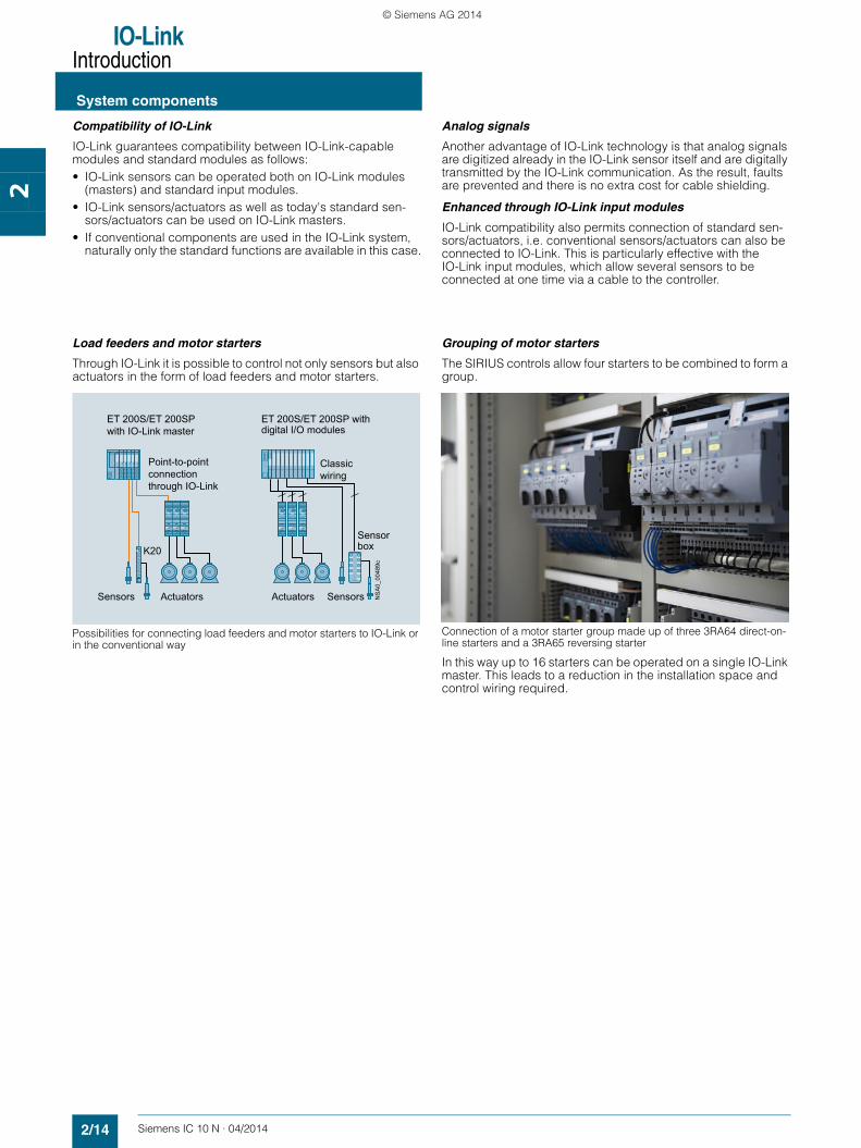
Load feeders and motor starters
Through IO-Link it is possible to control not only sensors but also actuators in the form of load feeders and motor starters.
Possibilities for connecting load feeders and motor starters to IO-Link or in the conventional way
Grouping of motor starters
The SIRIUS controls allow four starters to be combined to form a group.
Connection of a motor starter group made up of three 3RA64 direct-on-line starters and a 3RA65 reversing starter
In this way up to 16 starters can be operated on a single IO-Link master. This leads to a reduction in the installation space and control wiring required.
Sensors SensorsActuators Actuators
Point-to-pointconnection through IO-Link
Classicwiring
ET 200S/ET 200SPwith IO-Link master
ET 200S/ET 200SP with digital I/O modules
K20Sensorbox
NS
A0_
0048
9c
SIRIUS_IC10N_chap02_English_2014.book Seite 14 Dienstag, 20. Mai 2014 3:51 15
© Siemens AG 2014

IO-LinkIntroduction
2/15Siemens IC 10 N · 04/2014
System components
2
Monitoring relays
By using the monitoring relays with IO-Link it is now possible to send data that has already been recorded and evaluated in the
devices directly to the controller. This avoids the use of dupli-cated sensors.
Possibilities for connecting monitoring relays to IO-Link (left) or in the conventional way (right)
Wireless communication
Using an upstream IWLAN client module, such as SCALANCE W722-1 RJ45, allows IO-Link to be be integrated into the PROFINET world via a distributed I/O. Possible uses include acting as an alternative to fault-prone cable carrier or collector wire technology. The individual diagnostics options offered by
the various IO-Link devices provide greater transparency for the production process. Just like the parameter data for a device, these diagnostics data can be evaluated remotely using the possibilities offered by SIMATIC. This supports remote mainte-nance down to the lowest level in the field.
Wireless communication between Industrial Ethernet and IO-Link components
3
1 22
1
1
Feeder
PLC
Motor
3UG46monitoring relay
3UG46monitoring relay
3UG46monitoring relay
Analog signal
converter
Current transfor-
mers
Signaling of limit value violation plus measurement data transmission to PLCAutonomous operation without PLCSignaling of limit value violation to PLC
1
2
PLC
IO-Link master
3UG48monitoring relay
3UG48monitoring relay
3UG48monitoring relay Feeder
Motor
Signaling of limit value violation plus measurement data transmission to PLCAutonomous operation without PLC
1
23
IC01
_001
75
IO-Link
ET 200SP (ET 200S)with IO-Link master
Pump station Maintenance station
Control room
3RA6 Compact starter
IC01
_001
98b
Industrial Ethernet
Industrial Ethernet
IO-Link
SCALANCE W722-1 RJ45
SIMATIC HMI KTP 1500 Basic
SIMATICS7-300
SCALANCE W786-1 RJ45 Access Point
SIRIUS_IC10N_chap02_English_2014.book Seite 15 Dienstag, 20. Mai 2014 3:51 15
© Siemens AG 2014
IO-LinkIntroduction
System components
2/16 Siemens IC 10 N · 04/2014
2
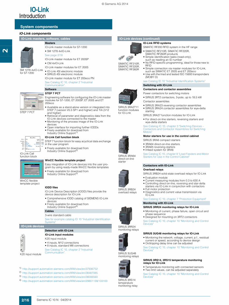
IO-Link components
1) http://support.automation.siemens.com/WW/view/en/37936752 2) http://support.automation.siemens.com/WW/view/en/38487085 3) http://support.automation.siemens.com/WW/view/en/38006560 4) http://support.automation.siemens.com/WW/view/en/29801139/133100
IO-Link masters, software, cablesMasters
SM 1278 4xIO-Link for S7-1200
IO-Link master module for S7-1200
• SM 1278 4xIO-Link
See page 2/18
IO-Link master module for ET 200SP
• CM 4xIO-Link
IO-Link master modules for ET 200S
• IO-Link 4SI electronic module• SIRIUS 4SI electronic module
IO-Link master module for ET 200eco PN
See Catalog IC 10, chapter 2 "Industrial Communication".
Software
STEP 7 PCT
STEP 7 PCT
Engineering software for configuring the IO-Link master modules for S7-1200, ET 200SP, ET 200S and ET 200eco
• Available as a stand-alone version or integrated into STEP 7 (version V5.5 SP1 and higher) and TIA (V12 and higher)
• Retrieval of parameter and diagnostics data from the IO-Link devices connected to the master
• Monitoring of the process image of the IO-Link devices
• Open interface for importing further IODDs • Freely available for download from
Industry Online Support1)
IO-Link Call function block
IO-Link Call function block
STEP 7 function block for easy acyclical data exchange in the user program
• Freely available for download from Industry Online Support2)
WinCC flexible template project
WinCC flexible template project
Easy integration of IO-Link devices into the user pro-gram by using ready-made WinCC flexible templates
• Freely available for download from Industry Online Support3)
IODD files
IO-Link Device Description (IODD) files provide the device description for IO-Link
• Comprehensive IODD catalog of SIEMENS IO-Link devices
• Freely available for download from Industry Online Support4)
Cables
3-wire standard cable
See for example catalog ID 10 "Industrial Identification Systems"
IO-Link devicesDetection with IO-Link
K20 input module
IO-Link input modules
K20 input module
• 4 inputs, M12 connections• 8 inputs, standard M8 connections
See Catalog IC 10, chapter 2 "Industrial Communication".
BOOLIOL_CALL
DWORDINT
DONEBUSY
INTINTINT RD_LEN
INTANY
BOOLERROR
IOL_STATUSSTATUS
BOOLBOOL
INT
BOOL
DWODWO
REQ
IDCAP
PORTIOL_INDEXIOL_SUBINDEX
LENRECORD_IOL_DATA
RD_WR
IC01
_001
97 IO-Link devices (continued)
SIMATIC RF210R, SIMATIC RF220R, SIMATIC RF260R
IO-Link RFID systems
SIMATIC RF200 RFID system in the HF range
• SIMATIC RF210R, SIMATIC RF220R, SIMATIC RF260R products
• Simple identification tasks (read-only), such as reading an ID number
• No RFID-specific programming, ideal for those new to RFID
• Simple connection via master modules for IO-Link, such as SIMATIC ET 200S and ET 200eco
• Use with the tried and tested ISO 15693 transponders (MOBY D)
see Catalog ID 10 "Industrial Identification Systems"
Switching with IO-Link
SIRIUS 3RA2711 function modules for IO-Link
Contactors and contactor assemblies
Power contactors for switching motors
• SIRIUS 3RT2 contactors, 3-pole, up to 18.5 kW
Contactor assemblies
• SIRIUS 3RA23 reversing contactor assemblies• SIRIUS 3RA24 contactor assemblies for wye-delta
starting
SIRIUS 3RA27 function modules for IO-Link
• For direct-on-line starters, reversing starters and wye-delta starters
See Catalog IC 10, chapter 3 "Switching Devices – Contactors and Contactor Assemblies for Switching Motors"
SIRIUS 3RA64 direct-on-line starter
Motor starters for use in the control cabinet
SIRIUS 3RA6 compact starters
• 3RA64 direct-on-line starters• 3RA65 reversing starters• Infeed system for 3RA6
See Catalog IC 10, chapter 8 "Load Feeders and Motor Starters for Use in the Control Cabinet"
Contactors with IO-Link
SIRIUS 3RB24overload relays
Overload relays
SIRIUS 3RB24 solid-state overload relays for IO-Link
• Evaluation module• Current measuring modules from 0.3 to 630 A• Controlling direct-on-line, reversing and star-delta
starters via IO-Link in conjunction with contactors• Full motor protection• Diagnostics and current value transmission via
IO-Link
See Catalog IC 10, chapter 7 "Protection Equipment"
Monitoring with IO-Link
SIRIUS 3RR24 monitoring relays
SIRIUS 3RR24 monitoring relays for IO-Link
• Monitoring of current, phase failure, open circuit and phase sequence
• Designed for mounting on 3RT2 contactors
See Catalog IC 10, chapter 10 "Monitoring and Control Devices"
SIRIUS 3UG48 monitoring relays
SIRIUS 3UG48 monitoring relays for IO-Link
• Monitoring the network, voltage, current, p.f., residual current or speed, according to device design
• On/tripping delay time can be adjusted
See Catalog IC 10, chapter 10 "Monitoring and Control Devices"
SIRIUS 3RS14 temperature monitoring relay
SIRIUS 3RS14, 3RS15 temperature monitoring relays for IO-Link
• Temperature monitoring with connected sensors• Two limit values, can be adjusted separately
See Catalog IC 10, chapter 10 "Monitoring and Control Devices"
SIRIUS_IC10N_chap02_English_2014.book Seite 16 Dienstag, 20. Mai 2014 3:51 15
© Siemens AG 2014
IO-LinkIntroduction
2/17Siemens IC 10 N · 04/2014
IO-Link Specification
2
■ Overview
Principles of the IO-Link Specification
According to the IO-Link Specification, communication functions as follows: • Transmission takes place via an unshielded three-wire cable
no more than 20 m long, of the kind normally used for standard sensors.
• Analog values which have already been digitized are transmit-ted in the form of message frames, which may correspond to 10 V or 4 to 20 mA.
• Digital communication from 0 to 24 V on the so-called C/Q cable
• Most of the values transmitted are measured values from the sensors which include the units.
• The sensors and actuators are described by the IO-Link Device Description (IODD)
• While the IO-Link Specification permits an infinite number of ports, an IO-Link master currently only supports four ports. Only one IO-Link device (slave) can be connected to each port (point-to-point connection).
• The transmission rates between IO-Link master and the devices are as follows:- via COM1: 4 800 Bd - via COM2: 38 400 Bd - via COM3: 230 400 Bd
• The average cycle time is 2 ms for the reading/writing of 16 data bits at a transmission rate of 38 400 Bd.
IO-Link protocol
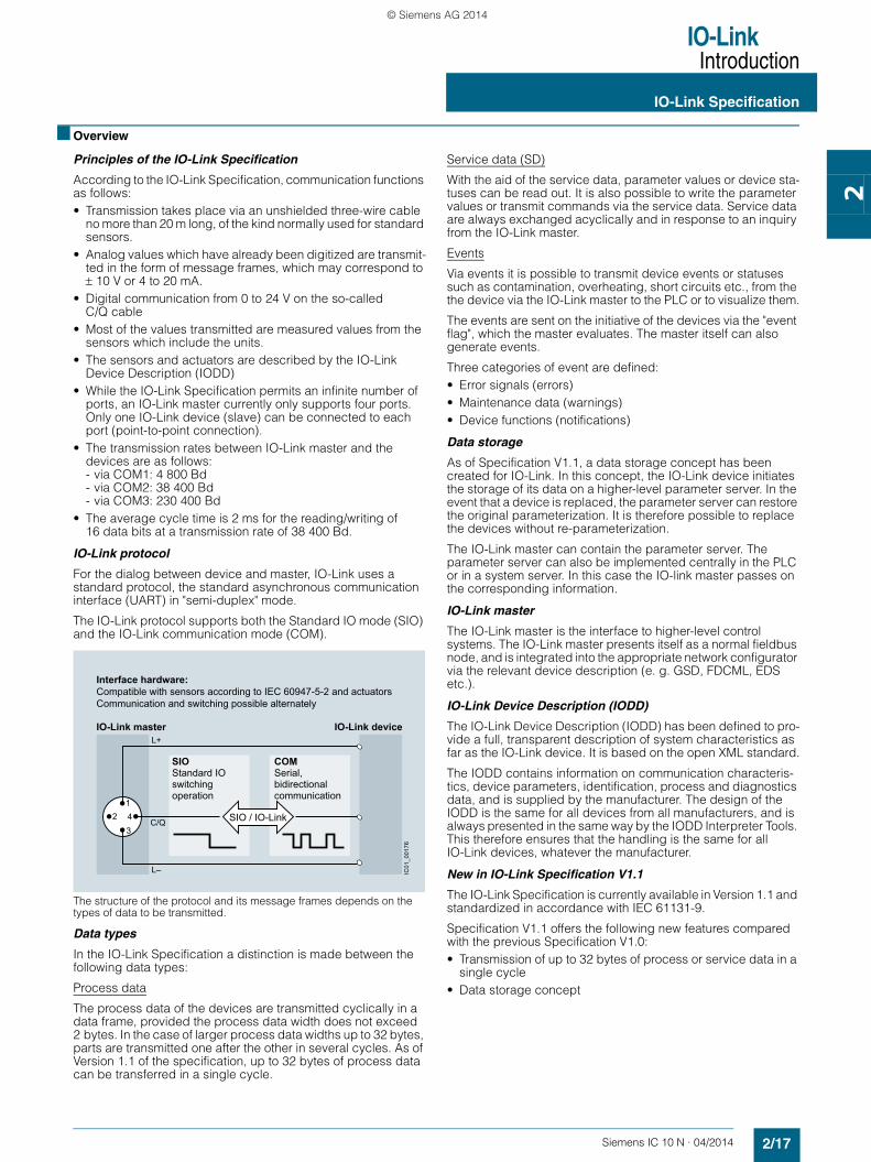
For the dialog between device and master, IO-Link uses a standard protocol, the standard asynchronous communication interface (UART) in "semi-duplex" mode.
The IO-Link protocol supports both the Standard IO mode (SIO) and the IO-Link communication mode (COM).
The structure of the protocol and its message frames depends on the types of data to be transmitted.
Data types
In the IO-Link Specification a distinction is made between the following data types:
Process data
The process data of the devices are transmitted cyclically in a data frame, provided the process data width does not exceed 2 bytes. In the case of larger process data widths up to 32 bytes, parts are transmitted one after the other in several cycles. As of Version 1.1 of the specification, up to 32 bytes of process data can be transferred in a single cycle.
Service data (SD)
With the aid of the service data, parameter values or device sta-tuses can be read out. It is also possible to write the parameter values or transmit commands via the service data. Service data are always exchanged acyclically and in response to an inquiry from the IO-Link master.
Events
Via events it is possible to transmit device events or statuses such as contamination, overheating, short circuits etc., from the the device via the IO-Link master to the PLC or to visualize them.
The events are sent on the initiative of the devices via the "event flag", which the master evaluates. The master itself can also generate events.
Three categories of event are defined:• Error signals (errors)• Maintenance data (warnings)• Device functions (notifications)
Data storage
As of Specification V1.1, a data storage concept has been created for IO-Link. In this concept, the IO-Link device initiates the storage of its data on a higher-level parameter server. In the event that a device is replaced, the parameter server can restore the original parameterization. It is therefore possible to replace the devices without re-parameterization.
The IO-Link master can contain the parameter server. The parameter server can also be implemented centrally in the PLC or in a system server. In this case the IO-link master passes on the corresponding information.
IO-Link master
The IO-Link master is the interface to higher-level control systems. The IO-Link master presents itself as a normal fieldbus node, and is integrated into the appropriate network configurator via the relevant device description (e. g. GSD, FDCML, EDS etc.).
IO-Link Device Description (IODD)
The IO-Link Device Description (IODD) has been defined to pro-vide a full, transparent description of system characteristics as far as the IO-Link device. It is based on the open XML standard.
The IODD contains information on communication characteris-tics, device parameters, identification, process and diagnostics data, and is supplied by the manufacturer. The design of the IODD is the same for all devices from all manufacturers, and is always presented in the same way by the IODD Interpreter Tools. This therefore ensures that the handling is the same for all IO-Link devices, whatever the manufacturer.
New in IO-Link Specification V1.1
The IO-Link Specification is currently available in Version 1.1 and standardized in accordance with IEC 61131-9.
Specification V1.1 offers the following new features compared with the previous Specification V1.0:• Transmission of up to 32 bytes of process or service data in a
single cycle• Data storage concept
IO-Link master
Interface hardware:Compatible with sensors according to IEC 60947-5-2 and actuatorsCommunication and switching possible alternately
IO-Link device
SIOStandard IOswitching operation
SIO / IO-Link
COMSerial, bidirectional communication
IC01
_001
76
L+
C/Q
L–
41
23
SIRIUS_IC10N_chap02_English_2014.book Seite 17 Dienstag, 20. Mai 2014 3:51 15
© Siemens AG 2014
IO-LinkMastersIO-Link master module for S7-1200SM 1278 4xIO-Link master
2/18 Siemens IC 10 N · 04/2014* You can order this quantity or a multiple thereof.
Illustrations are approximate
2
■ Overview
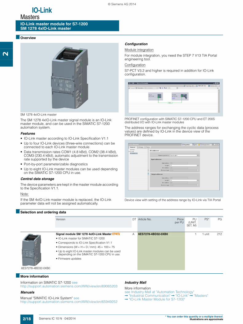
SM 1278 4xIO-Link master
The SM 1278 4xIO-Link master signal module is an IO-Link master module, and can be used in the SIMATIC S7-1200 automation system.
Features• IO-Link master according to IO-Link Specification V1.1• Up to four IO-Link devices (three-wire connections) can be
connected to each IO-Link master module • Data transmission rates COM1 (4.8 kBd), COM2 (38.4 kBd),
COM3 (230.4 kBd), automatic adjustment to the transmission rate supported by the device
• Port-by-port parameterizable diagnostics• Up to eight IO-Link master modules can be used depending
on the SIMATIC S7-1200 CPU in use.
Central data storage
The device parameters are kept in the master module according to the Specification V1.1.
Note:
If the SM 4xIO-Link master module is replaced, the IO-Link parameter data will not be assigned automatically.
Configuration
Module integration
For module integration, you need the STEP 7 V13 TIA Portal engineering tool.
Configuration
S7-PCT V3.2 and higher is required in addition for IO-Link configuration.
PROFINET configuration with SIMATIC S7-1200 CPU and ET 200S distributed I/O with IO-Link master modules
The address ranges for exchanging the cyclic data (process values) are defined by IO-Link in the device view of the PROFINET device.
Device view with setting of the address range by IO-Link via TIA Portal
■ Selection and ordering data
■ More information
Information on SIMATIC S7-1200 see http://support.automation.siemens.com/WW/view/en/69065203
Manuals
Manual "SIMATIC IO-Link System" seehttp://support.automation.siemens.com/WW/view/en/65949252
Industry Mall
More information see Industry Mall at "Automation Technology" ➞ "Industrial Communication" ➞ "IO-Link" ➞ "Masters" ➞ "IO-Link Master Module for S7-1200"
Version DT Article No. Priceper PU
PU(UNIT,
SET, M)
PS* PG
6ES7278-4BD32-0XB0
Signal module SM 1278 4xIO-Link Master A 6ES7278-4BD32-0XB0 1 1 unit 212
• IO-Link master for SIMATIC S7-1200
• Corresponds to IO-Link Specification V1.1
• Dimensions (W H D / mm): 45 100 75
• Up to eight IO-Link master modules can be used depending on the SIMATIC S7-1200 CPU in use.
• Firmware updates
SIRIUS_IC10N_chap02_English_2014.book Seite 18 Dienstag, 20. Mai 2014 3:51 15
© Siemens AG 2014
Siemens IC 10 N · 04/2014
14
14
Price groupsPG 42C
14/2 AS-Interface block library for SIMATIC PCS 7
Parameterization, Configuration and Visualization with SIRIUS
SIRIUS_IC10N_chap14_English_2014.book Seite 1 Donnerstag, 15. Mai 2014 12:27 12
© Siemens AG 2014
Parameterization, Configuration and Visualization with SIRIUS
AS-Interface block libraryfor SIMATIC PCS 7
14/2 Siemens IC 10 N · 04/2014
14
■ Overview
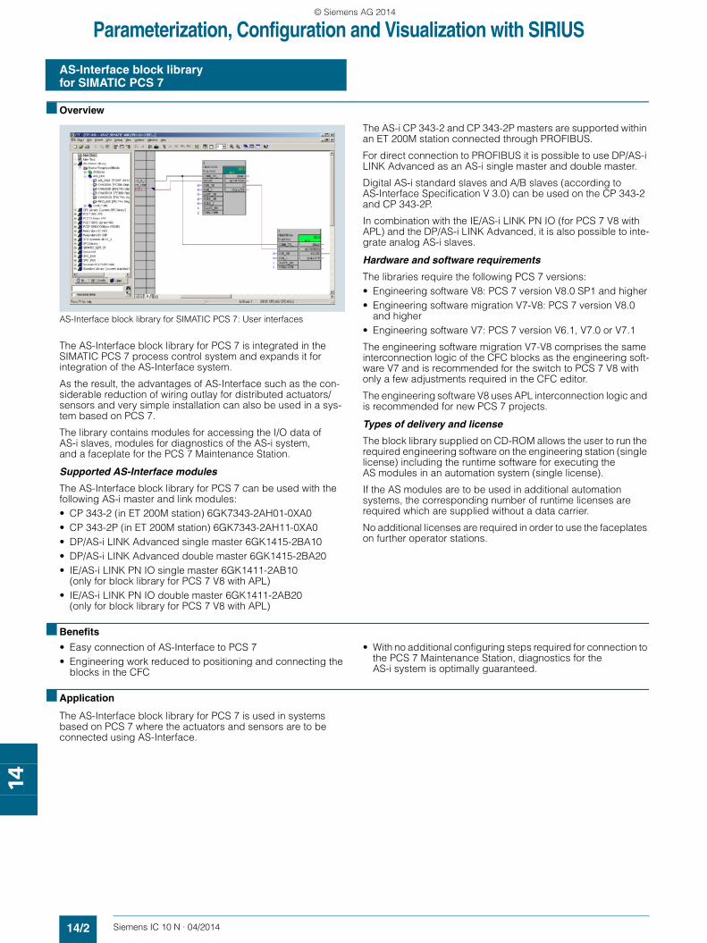
AS-Interface block library for SIMATIC PCS 7: User interfaces
The AS-Interface block library for PCS 7 is integrated in the SIMATIC PCS 7 process control system and expands it for integration of the AS-Interface system.
As the result, the advantages of AS-Interface such as the con-siderable reduction of wiring outlay for distributed actuators/sensors and very simple installation can also be used in a sys-tem based on PCS 7.
The library contains modules for accessing the I/O data of AS-i slaves, modules for diagnostics of the AS-i system, and a faceplate for the PCS 7 Maintenance Station.
Supported AS-Interface modules
The AS-Interface block library for PCS 7 can be used with the following AS-i master and link modules: • CP 343-2 (in ET 200M station) 6GK7343-2AH01-0XA0• CP 343-2P (in ET 200M station) 6GK7343-2AH11-0XA0 • DP/AS-i LINK Advanced single master 6GK1415-2BA10 • DP/AS-i LINK Advanced double master 6GK1415-2BA20• IE/AS-i LINK PN IO single master 6GK1411-2AB10
(only for block library for PCS 7 V8 with APL)• IE/AS-i LINK PN IO double master 6GK1411-2AB20
(only for block library for PCS 7 V8 with APL)
The AS-i CP 343-2 and CP 343-2P masters are supported within an ET 200M station connected through PROFIBUS.
For direct connection to PROFIBUS it is possible to use DP/AS-i LINK Advanced as an AS-i single master and double master.
Digital AS-i standard slaves and A/B slaves (according to AS-Interface Specification V 3.0) can be used on the CP 343-2 and CP 343-2P.
In combination with the IE/AS-i LINK PN IO (for PCS 7 V8 with APL) and the DP/AS-i LINK Advanced, it is also possible to inte-grate analog AS-i slaves.
Hardware and software requirements
The libraries require the following PCS 7 versions:• Engineering software V8: PCS 7 version V8.0 SP1 and higher• Engineering software migration V7-V8: PCS 7 version V8.0
and higher• Engineering software V7: PCS 7 version V6.1, V7.0 or V7.1
The engineering software migration V7-V8 comprises the same interconnection logic of the CFC blocks as the engineering soft-ware V7 and is recommended for the switch to PCS 7 V8 with only a few adjustments required in the CFC editor.
The engineering software V8 uses APL interconnection logic and is recommended for new PCS 7 projects.
Types of delivery and license
The block library supplied on CD-ROM allows the user to run the required engineering software on the engineering station (single license) including the runtime software for executing the AS modules in an automation system (single license).
If the AS modules are to be used in additional automation systems, the corresponding number of runtime licenses are required which are supplied without a data carrier.
No additional licenses are required in order to use the faceplates on further operator stations.
■ Benefits
• Easy connection of AS-Interface to PCS 7• Engineering work reduced to positioning and connecting the
blocks in the CFC
• With no additional configuring steps required for connection to the PCS 7 Maintenance Station, diagnostics for the AS-i system is optimally guaranteed.
■ Application
The AS-Interface block library for PCS 7 is used in systems based on PCS 7 where the actuators and sensors are to be connected using AS-Interface.
SIRIUS_IC10N_chap14_English_2014.book Seite 2 Donnerstag, 15. Mai 2014 12:27 12
© Siemens AG 2014
Parameterization, Configuration and Visualization with SIRIUS
AS-Interface block libraryfor SIMATIC PCS 7
14/3Siemens IC 10 N · 04/2014* You can order this quantity or a multiple thereof.Illustrations are approximate
14
■ Selection and ordering data
Version DT Article No. Priceper PU
PU(UNIT,
SET, M)
PS* PG
AS-Interface block library for SIMATIC PCS 7 Version V8 with Advanced Process Library (APL)
3ZS1635-1XX02-0YA0
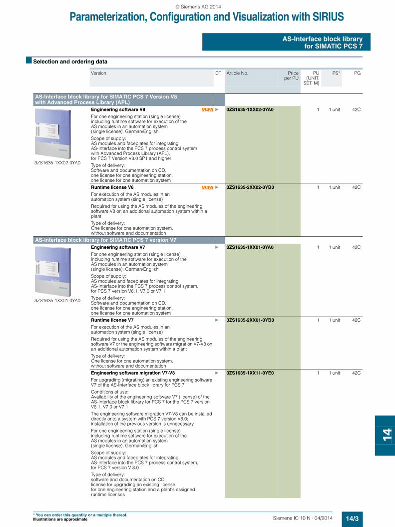
Engineering software V8
For one engineering station (single license) including runtime software for execution of the AS modules in an automation system (single license), German/English
Scope of supply: AS modules and faceplates for integrating AS-Interface into the PCS 7 process control system with Advanced Process Library (APL), for PCS 7 Version V8.0 SP1 and higher
Type of delivery: Software and documentation on CD, one license for one engineering station, one license for one automation system
} 3ZS1635-1XX02-0YA0 1 1 unit 42C
Runtime license V8
For execution of the AS modules in an automation system (single license)
Required for using the AS modules of the engineering software V8 on an additional automation system within a plant
Type of delivery:One license for one automation system, without software and documentation
} 3ZS1635-2XX02-0YB0 1 1 unit 42C
AS-Interface block library for SIMATIC PCS 7 version V7
3ZS1635-1XX01-0YA0
Engineering software V7
For one engineering station (single license) including runtime software for execution of the AS modules in an automation system (single license), German/English
Scope of supply: AS modules and faceplates for integrating AS-Interface into the PCS 7 process control system, for PCS 7 version V6.1, V7.0 or V7.1
Type of delivery: Software and documentation on CD, one license for one engineering station, one license for one automation system
} 3ZS1635-1XX01-0YA0 1 1 unit 42C
Runtime license V7
For execution of the AS modules in an automation system (single license)
Required for using the AS modules of the engineering software V7 or the engineering software migration V7-V8 on an additional automation system within a plant
Type of delivery:One license for one automation system, without software and documentation
} 3ZS1635-2XX01-0YB0 1 1 unit 42C
Engineering software migration V7-V8
For upgrading (migrating) an existing engineering software V7 of the AS-Interface block library for PCS 7
Conditions of use: Availability of the engineering software V7 (license) of the AS-Interface block library for PCS 7 for the PCS 7 version V6.1, V7.0 or V7.1
The engineering software migration V7-V8 can be installed directly onto a system with PCS 7 version V8.0; installation of the previous version is unnecessary.
For one engineering station (single license) including runtime software for execution of the AS modules in an automation system (single license), German/English
Scope of supply:AS modules and faceplates for integrating AS-Interface into the PCS 7 process control system, for PCS 7 version V 8.0
Type of delivery:software and documentation on CD, license for upgrading an existing license for one engineering station and a plant's assigned runtime licenses
} 3ZS1635-1XX11-0YE0 1 1 unit 42C
SIRIUS_IC10N_chap14_English_2014.book Seite 3 Donnerstag, 15. Mai 2014 12:27 12
© Siemens AG 2014
Parameterization, Configuration and Visualization with SIRIUS
AS-Interface block libraryfor SIMATIC PCS 7
14/4 Siemens IC 10 N · 04/2014
14
■ More information
Programming Manual for AS-Interface Block Library for SIMATIC PCS 7 Version V8 with Advanced Process Library (APL) see http://support.automation.siemens.com/WW/view/en/37432054/133300.
Programming Manual for AS-Interface Block Library for SIMATIC PCS 7 Version V6.1/V7/V8 (migration) see http://support.automation.siemens.com/WW/view/en/46504691.
Notes:
The associated service pack SP1 of the block library is included in the scope of delivery of engineering software V7 and engineering software migration V7-V8.
Service pack SP1 can be downloaded from the Internet see http://support.automation.siemens.com/WW/view/en/37432054/133100.
SIRIUS_IC10N_chap14_English_2014.book Seite 4 Donnerstag, 15. Mai 2014 12:27 12
© Siemens AG 2014
Siemens IC 10 N · 04/2014
16
16
16/2 Subject index
16/2 Article number index
16/3 Conditions of sale and delivery
Appendix
IC10N_chap16_English_2015.book Seite 1 Donnerstag, 15. Mai 2014 12:28 12
© Siemens AG 2014
Appendix
Subject index
16/2 Siemens IC 10 N · 04/2014
16
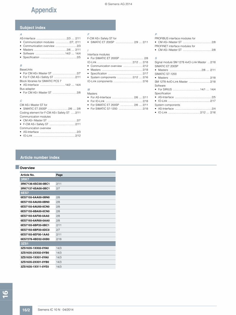
AAS-Interface .......................................2/3 ... 2/11• Communication modules ................. 2/7, 2/11• Communication overview ...........................2/3• Masters ..........................................2/6 ... 2/11• Software ......................................14/2 ... 14/4• Specification ...............................................2/5
BBaseUnits• For CM AS-i Master ST ...............................2/7• For F-CM AS-i Safety ST ...........................2/11Block libraries for SIMATIC PCS 7• AS-Interface ................................14/2 ... 14/4Bus adapter• For CM AS-i Master ST ...............................2/8
CCM AS-i Master ST for• SIMATIC ET 200SP ..........................2/6 ... 2/8Coding element for F-CM AS-i Safety ST .....2/11Communication modules• CM AS-i Master ST .....................................2/7• F-CM AS-i Safety ST .................................2/11Communication overview• AS-Interface ...............................................2/3• IO-Link ......................................................2/12
FF-CM AS-i Safety ST for• SIMATIC ET 200SP ....................... 2/9 ... 2/11
IInterface modules• For SIMATIC ET 200SP .............................. 2/8IO-Link ............................................. 2/12 ... 2/18• Communication overview ........................ 2/12• Masters .................................................... 2/18• Specification ............................................ 2/17• System components ................... 2/12 ... 2/16IO-Link components ..................................... 2/16
MMasters• For AS-Interface ............................ 2/6 ... 2/11• For IO-Link ............................................... 2/18• For SIMATIC ET 200SP ................. 2/6 ... 2/11• For SIMATIC S7-1200 .............................. 2/18
PPROFIBUS interface modules for• CM AS-i Master ST .....................................2/8PROFINET interface modules for• CM AS-i Master ST .....................................2/8
SSignal module SM 1278 4xIO-Link Master ...2/18SIMATIC ET 200SP• Masters .........................................2/6 ... 2/11SIMATIC S7-1200• Masters ....................................................2/18SM 1278 4xIO-Link Master ...........................2/18Software• For SIRIUS ...................................14/1 ... 14/4Specification• AS-Interface ...............................................2/5• IO-Link ......................................................2/17System components• AS-Interface ...............................................2/4• IO-Link .........................................2/12 ... 2/16
■ Overview
Article number index
Article No. Page
3RK73RK7136-6SC00-0BC1 2/11
3RK7137-6SA00-0BC1 2/7
6ES76ES7155-6AA00-0BN0 2/8
6ES7155-6AU00-0BN0 2/8
6ES7155-6AU00-0CN0 2/8
6ES7155-6BA00-0CN0 2/8
6ES7193-6AF00-0AA0 2/8
6ES7193-6AR00-0AA0 2/8
6ES7193-6BP20-0BC1 2/11
6ES7193-6BP20-0DC0 2/7
6ES7193-6EF00-1AA0 2/11
6ES7278-4BD32-0XB0 2/18
3ZS13ZS1635-1XX02-0YA0 14/3
3ZS1635-2XX02-0YB0 14/3
3ZS1635-1XX01-0YA0 14/3
3ZS1635-2XX01-0YB0 14/3
3ZS1635-1XX11-0YE0 14/3
IC10N_chap16_English_2015.book Seite 2 Donnerstag, 15. Mai 2014 12:28 12
© Siemens AG 2014

Appendix
16/3Siemens IC 10 N · 04/2014
Conditions of sale and delivery
16
■ 1. General Provisions
By using this catalog you can acquire hardware and software products described therein from Siemens AG subject to the following Terms and Conditions of Sale and Delivery (hereinafter referred to as "T&C"). Please note that the scope, the quality and the conditions for supplies and services, including software products, by any Siemens entity having a registered office outside Germany, shall be subject exclusively to the General Terms and Conditions of the respective Siemens entity. The following T&C apply exclusively for orders placed with Siemens Aktiengesellschaft, Germany.
1.1 For customers with a seat or registered office in GermanyFor customers with a seat or registered office in Germany, the following applies subordinate to the T&C:• the "General Terms of Payment"1) and,• for software products, the "General License Conditions for
Software Products for Automation and Drives for Customers with a Seat or Registered Office in Germany"1) and,
• for other supplies and services, the "General Conditions for the Supply of Products and Services of the Electrical and Electronics Industry"1).
1.2 For customers with a seat or registered office outside GermanyFor customers with a seat or registered office outside Germany, the following applies subordinate to the T&C:• the "General Terms of Payment"1) and,• for software products, the "General License Conditions for
Software Products for Automation and Drives for Customers with a Seat or Registered Office outside of Germany"1) and
• for other supplies and/or services, the "General Conditions for Supplies of Siemens Industry for Customers with a Seat or Registered Office outside of Germany"1).
■ 2. Prices
The prices are in € (Euro) ex point of delivery, exclusive of packaging.The sales tax (value added tax) is not included in the prices. It shall be charged separately at the respective rate according to the applicable statutory legal regulations.Prices are subject to change without prior notice. We will charget the prices valid at the time of delivery.To compensate for variations in the price of raw materials (e.g. silver, copper, aluminum, lead, gold, dysprosium and neodym), surcharges are calculated on a daily basis using the so-called metal factor for products containing these raw materials. A surcharge for the respective raw material is calculated as a supplement to the price of a product if the basic official price of the raw material in question is exceeded.The metal factor of a product indicates the basic official price (for those raw materials concerned) as of which the surcharges on the price of the product are applied, and with what method of calculation. An exact explanation of the metal factor can be downloaded at:www.siemens.com/automation/salesmaterial-as/catalog/en/ terms_of_trade_en.pdfTo calculate the surcharge (except in the cases of dysprosium and neodym), the official price from the day prior to that on which the order was received or the release order was effected is used.To calculate the surcharge applicable to dysprosium and neodym ("rare earths"), the corresponding three-month basic average price in the quarter prior to that in which the order was received or the release order was effected is used with a one-month buffer (details on the calculation can be found in the explanation of the metal factor).
■ 3. Additional Terms and Conditions
The dimensions are in mm. In Germany, according to the German law on units in measuring technology, data in inches apply only to devices for export.Illustrations are not binding.Insofar as there are no remarks on the individual pages of this catalog - especially with regard to data, dimensions and weights given - these are subject to change without prior notice.
■ 4. Export regulations
We shall not be obligated to fulfill any agreement if such fulfillment is prevented by any impediments arising out of national or international foreign trade or customs requirements or any embargoes and/or other sanctions.Export of goods listed in this catalog may be subject to licensing requirements. We will indicate in the delivery details whether licenses are required under German, European and US export lists. Goods labeled with "AL" not equal to "N" are subject to European or German export authorization when being exported out of the EU. Goods labeled with "ECCN" not equal to "N" are subject to US re-export authorization. The export indications can be viewed in advance in the description of the respective goods on the Industry Mall, our online catalog system. Only the export labels "AL" and "ECCN" indicated on order confirmations, delivery notes and invoices are authoritative.Even without a label, or with label "AL:N" or "ECCN:N", authori-zation may be required i .a. due to the final disposition and intended use of goods.If you transfer goods (hardware and/or software and/or technology as well as corresponding documentation, regardless of the mode of provision) delivered by us or works and services (including all kinds of technical support) performed by us to a third party worldwide, you must comply with all applicable national and international (re-)export control regulations.If required for the purpose of conducting export control checks, you (upon request by us) shall promptly provide us with all infor-mation pertaining to the particular end customer, final dispo-sition and intended use of goods delivered by us respectively works and services provided by us, as well as to any export control restrictions existing in this relation.The products listed in this catalog may be subject to European/German and/or US export regulations. Any export requiring approval is therefore subject to authorization by the relevant authorities.Errors excepted and subject to change without prior notice.
1) The text of the Terms and Conditions of Siemens AG can be downloaded atwww.siemens.com/automation/salesmaterial-as/catalog/en/ terms_of_trade_en.pdf
IC10N_chap16_English_2015.book Seite 3 Donnerstag, 15. Mai 2014 12:28 12
© Siemens AG 2014

Appendix
Notes
16/4 Siemens IC 10 N · 04/2014
16
IC10N_chap16_English_2015.book Seite 4 Donnerstag, 15. Mai 2014 12:28 12
© Siemens AG 2014

CatalogsIndustry Automation, Drive Technologies and Low-Voltage Power Distribution
Further information can be obtained from our branch officeslisted at www.siemens.com/automation/partner
System Solutions for Industry Interactive Catalog on DVD
Catalog
Products for Automation and Drives, Low-Voltage Power Distribution and Electrical Installation Technology
CA 01
Building ControlGAMMA Building Control ET G1
Drive SystemsSINAMICS G130 Drive Converter Chassis Units SINAMICS G150 Drive Converter Cabinet Units
D 11
SINAMICS GM150, SINAMICS SM150 Medium-Voltage Converters
D 12
SINAMICS PERFECT HARMONY GH180 Medium-Voltage Air-Cooled Drives Germany Edition
D 15.1
SINAMICS G180 Converters – Compact Units, Cabinet Systems, Cabinet Units Air-Cooled and Liquid-Cooled
D 18.1
SINAMICS S120 Chassis Format Units and Cabinet Modules SINAMICS S150 Converter Cabinet Units
D 21.3
SINAMICS DCM Converter Units D 23.1SINAMICS DCM Cabinet D 23.2SINAMICS and Motors for Single-Axis Drives D 31Three-Phase Induction Motors SIMOTICS HV, SIMOTICS TN• Series H-compact• Series H-compact PLUS
D 84.1
Asynchronous Motors Standardline D 86.1Synchronous Motors with Permanent-Magnet Technology, HT-direct
D 86.2
DC Motors DA 12SIMOREG DC MASTER 6RA70 Digital Chassis Converters
DA 21.1
SIMOREG K 6RA22 Analog Chassis Converters DA 21.2Digital: SIMOREG DC MASTER 6RM70 Digital
Converter Cabinet UnitsDA 22
SIMOVERT PM Modular Converter Systems DA 45SIEMOSYN Motors DA 48MICROMASTER 420/430/440 Inverters DA 51.2MICROMASTER 411/COMBIMASTER 411 DA 51.3SIMOVERT MASTERDRIVES Vector Control DA 65.10SIMOVERT MASTERDRIVES Motion Control DA 65.11Synchronous and asynchronous servomotors for SIMOVERT MASTERDRIVES
DA 65.3
SIMODRIVE 611 universal and POSMO DA 65.4
Note: Additional catalogs on SIMODRIVE or SINAMICS drive systems and SIMOTICS motors with SINUMERIK and SIMOTION can be found under Motion Control
Low-Voltage Three-Phase-MotorsSIMOTICS Low-Voltage Motors D 81.1MOTOX Geared Motors D 87.1SIMOGEAR Geared Motors MD 50.1SIMOGEAR Gearboxes with adapter MD 50.11
Mechanical Driving MachinesFLENDER Standard Couplings MD 10.1FLENDER High Performance Couplings MD 10.2FLENDER SIG Standard industrial gear unit MD 30.1FLENDER SIP Standard industrial planetary gear units MD 31.1
Process Instrumentation and AnalyticsField Instruments for Process Automation FI 01Digital: SIPART Controllers and Software MP 31Products for Weighing Technology WT 10Digital: Process Analytical Instruments PA 01Digital: Process Analytics,
Components for the System IntegrationPA 11
Digital: These catalogs are only available as a PDF and/or as an e-book.
Low-Voltage Power Distribution and Electrical Installation Technology
Catalog
SENTRON · SIVACON · ALPHA Protection, Switching, Measuring and Monitoring Devices, Switchboards and Distribution Systems
LV 10
Standards-Compliant Components for Photovoltaic Plants
LV 11
3WT Air Circuit Breakers up to 4000 A LV 353VT Molded Case Circuit Breakers up to 1600 A LV 36Digital: SIVACON System Cubicles, System Lighting
and System Air-ConditioningLV 50
Digital: ALPHA Distribution Systems LV 51ALPHA FIX Terminal Blocks LV 52SIVACON S4 Power Distribution Boards LV 56Digital: SIVACON 8PS Busbar Trunking Systems LV 70Digital: DELTA Switches and Socket Outlets ET D1
Motion ControlSINUMERIK & SIMODRIVE Automation Systems for Machine Tools
NC 60
SINUMERIK & SINAMICS Equipment for Machine Tools
NC 61
SINUMERIK 840D sl Type 1B Equipment for Machine Tools
NC 62
SINUMERIK 808 Equipment for Machine Tools
NC 81.1
SINUMERIK 828 Equipment for Machine Tools
NC 82
SIMOTION, SINAMICS S120 & SIMOTICS Equipment for Production Machines
PM 21
Drive and Control Components for Cranes CR 1
Power SupplyPower supply SITOP KT 10.1
Safety IntegratedSafety Technology for Factory Automation SI 10
SIMATIC HMI/PC-based AutomationHuman Machine Interface Systems/PC-based Automation
ST 80/ ST PC
SIMATIC IdentIndustrial Identification Systems ID 10
SIMATIC Industrial Automation SystemsProducts for Totally Integrated Automation ST 70SIMATIC PCS 7 Process Control System System components
ST PCS 7
SIMATIC PCS 7 Process Control System Technology components
ST PCS 7 T
Add-ons for the SIMATIC PCS 7 Process Control System
ST PCS 7 AO
SIMATIC NETIndustrial Communication IK PI
SIRIUS Industrial Controls SIRIUS Industrial Controls IC 10
Information and Download Center
Digital versions of the catalogs are available on the Internet at:www.siemens.com/industry/infocenter There you’ll find additional catalogs in other languages.
Please note the section “Downloading catalogs” on page “Online services” in the appendix of this catalog.
U3_IADT-LP_en_4f.fm Seite 2 Montag, 19. Mai 2014 1:51 13
© Siemens AG 2014
Industrial ControlsSIRIUS
Get more information
Control Components and Systems Engineering:www.siemens.com/sirius
The information provided in this catalog contains merely general descriptions or characteristics of performance which in case of actual use do not always apply as described or which may change as a result of further development of the products. An obligation to provide the respective characteristics shall only exist if expressly agreed in the terms of contract. Availability and technical specifications are subject to change without notice.All product designations may be trademarks or product names of Siemens AG or supplier companies whose use by third parties for their own purposes could violate the rights of the owners.
Siemens AGIndustry SectorControl Components andSystems EngineeringPostfach 235590713 FÜRTHGERMANY
Subject to change without prior noticePDF/E-Book (E86060-K1010-A151-A4-7600)C.8107.10.22KG 0514 32 En Produced in Germany© Siemens AG 2014
www.siemens.com/automation
Security information
Siemens provides products and solutions with industrial security functions that support the secure operation of plants, solutions, machines, equipment and/or networks. They are important components in a holistic industrial security concept. With this in mind, Siemens’ products and solutions undergo continuous development. Siemens recommends strongly that you regularly check for product updates.
For the secure operation of Siemens products and solutions, it is necessary to take suitable preventive action (e.g. cell protection concept) and integrate each component into a holistic, state-of-the-art industrial security concept. Third-party products that may be in use should also be considered. For more information about industrial security, visithttp://www.siemens.com/industrialsecurity.
To stay informed about product updates as they occur, sign up for a product-specific newsletter. For more information, visithttp://support.automation.siemens.com.
umschlag_IC10N_04_2014_EN.indd 1umschlag_IC10N_04_2014_EN.indd 1 19.05.2014 14:01:2219.05.2014 14:01:22
© Siemens AG 2014
![Basics of Switchboards[1]](https://static.fdocuments.in/doc/165x107/55cf9a6b550346d033a1a0f3/basics-of-switchboards1.jpg)