SPECTRA SERIES SWITCHBOARDS
104
GE Industrial Systems SPECTRA SERIES SPECTRA SERIES SWIT SWIT CHBO CHBO ARDS ARDS
Transcript of SPECTRA SERIES SWITCHBOARDS
GE Industrial Systems
SPECTRA SERIESSPECTRA SERIESSWITSWITCHBOCHBOARDSARDS
1
Section 1 - Introduction
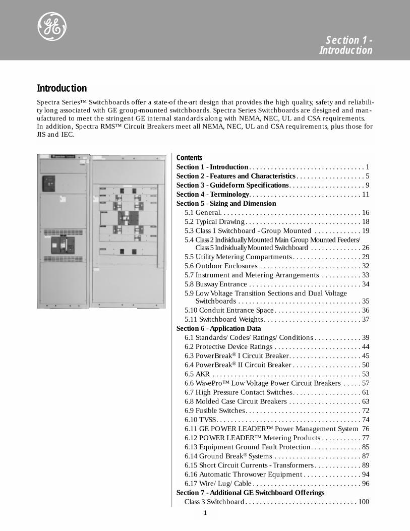
ContentsSection 1 - Introduction . . . . . . . . . . . . . . . . . . . . . . . . . . . . . . . . 1Section 2 - Features and Characteristics . . . . . . . . . . . . . . . . . . . 5Section 3 - Guideform Specifications. . . . . . . . . . . . . . . . . . . . . 9Section 4 - Terminology. . . . . . . . . . . . . . . . . . . . . . . . . . . . . . . 11Section 5 - Sizing and Dimension
5.1 General. . . . . . . . . . . . . . . . . . . . . . . . . . . . . . . . . . . . . . . 165.2 Typical Drawing . . . . . . . . . . . . . . . . . . . . . . . . . . . . . . . . 185.3 Class 1 Switchboard - Group Mounted . . . . . . . . . . . . . 195.4 Class 2 Individually Mounted Main Group Mounted Feeders/
Class 5 Individually Mounted Switchboard . . . . . . . . . . . . . . 265.5 Utility Metering Compartments . . . . . . . . . . . . . . . . . . . 295.6 Outdoor Enclosures . . . . . . . . . . . . . . . . . . . . . . . . . . . . 325.7 Instrument and Metering Arrangements . . . . . . . . . . . 335.8 Busway Entrance . . . . . . . . . . . . . . . . . . . . . . . . . . . . . . . 345.9 Low Voltage Transition Sections and Dual Voltage
Switchboards . . . . . . . . . . . . . . . . . . . . . . . . . . . . . . . . . . 355.10 Conduit Entrance Space. . . . . . . . . . . . . . . . . . . . . . . . 365.11 Switchboard Weights . . . . . . . . . . . . . . . . . . . . . . . . . . . 37
Section 6 - Application Data6.1 Standards/Codes/Ratings/Conditions . . . . . . . . . . . . . 396.2 Protective Device Ratings . . . . . . . . . . . . . . . . . . . . . . . . 446.3 PowerBreak® I Circuit Breaker. . . . . . . . . . . . . . . . . . . . 456.4 PowerBreak® II Circuit Breaker . . . . . . . . . . . . . . . . . . . 506.5 AKR . . . . . . . . . . . . . . . . . . . . . . . . . . . . . . . . . . . . . . . . . 536.6 WavePro™ Low Voltage Power Circuit Breakers . . . . . 576.7 High Pressure Contact Switches. . . . . . . . . . . . . . . . . . . 616.8 Molded Case Circuit Breakers . . . . . . . . . . . . . . . . . . . . 636.9 Fusible Switches. . . . . . . . . . . . . . . . . . . . . . . . . . . . . . . . 726.10 TVSS. . . . . . . . . . . . . . . . . . . . . . . . . . . . . . . . . . . . . . . . 746.11 GE POWER LEADER™ Power Management System 766.12 POWER LEADER™ Metering Products . . . . . . . . . . . 776.13 Equipment Ground Fault Protection. . . . . . . . . . . . . . 856.14 Ground Break® Systems . . . . . . . . . . . . . . . . . . . . . . . . 876.15 Short Circuit Currents - Transformers . . . . . . . . . . . . . 896.16 Automatic Throwover Equipment . . . . . . . . . . . . . . . . 946.17 Wire/Lug/Cable . . . . . . . . . . . . . . . . . . . . . . . . . . . . . . 96
Section 7 - Additional GE Switchboard OfferingsClass 3 Switchboard. . . . . . . . . . . . . . . . . . . . . . . . . . . . . . . 100
IntroductionSpectra Series™ Switchboards offer a state-of the-art design that provides the high quality, safety and reliabili-ty long associated with GE group-mounted switchboards. Spectra Series Switchboards are designed and man-ufactured to meet the stringent GE internal standards along with NEMA, NEC, UL and CSA requirements.In addition, Spectra RMS™ Circuit Breakers meet all NEMA, NEC, UL and CSA requirements, plus those forJIS and IEC.
2
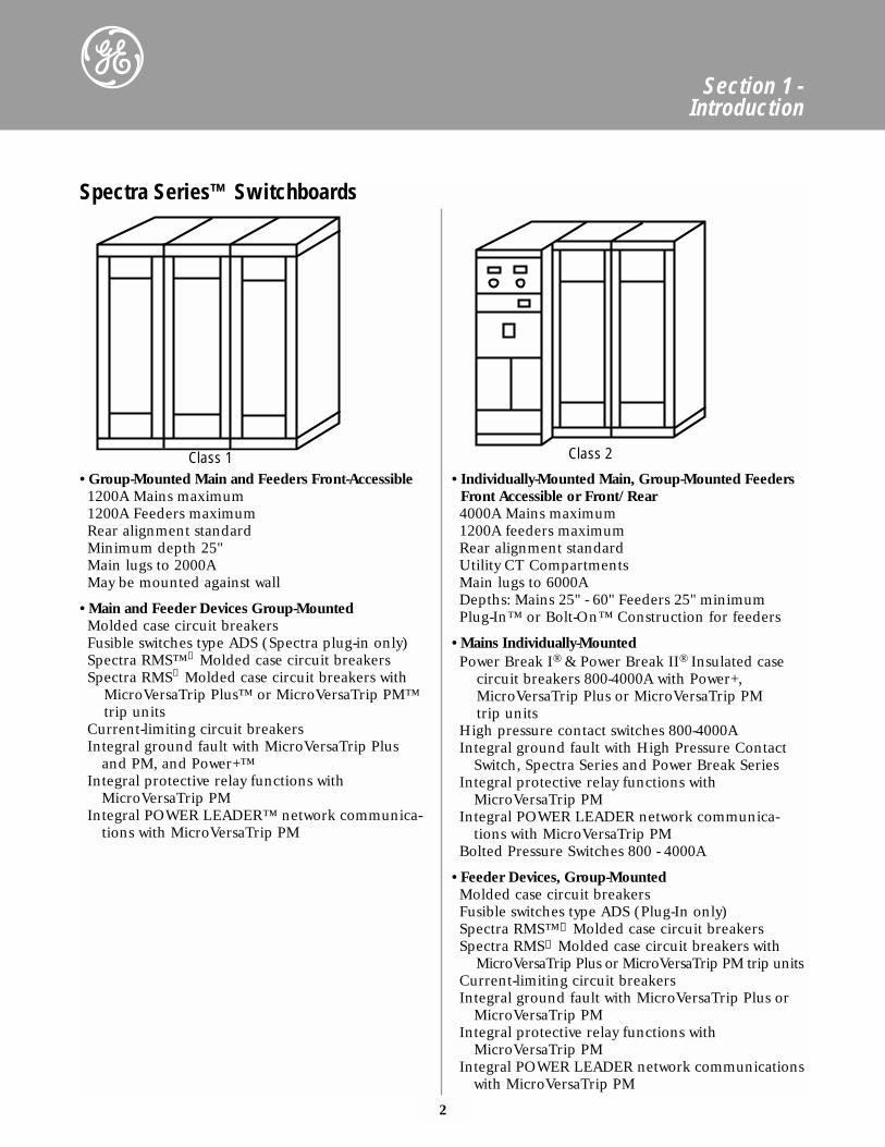
Spectra Series™ Switchboards
• Group-Mounted Main and Feeders Front-Accessible1200A Mains maximum1200A Feeders maximumRear alignment standardMinimum depth 25"Main lugs to 2000AMay be mounted against wall
• Main and Feeder Devices Group-MountedMolded case circuit breakersFusible switches type ADS (Spectra plug-in only)Spectra RMS™① Molded case circuit breakersSpectra RMS① Molded case circuit breakers with
MicroVersaTrip Plus™ or MicroVersaTrip PM™trip units
Current-limiting circuit breakersIntegral ground fault with MicroVersaTrip Plus
and PM, and Power+™Integral protective relay functions with
MicroVersaTrip PMIntegral POWER LEADER™ network communica-
tions with MicroVersaTrip PM
• Individually-Mounted Main, Group-Mounted FeedersFront Accessible or Front/Rear4000A Mains maximum1200A feeders maximumRear alignment standardUtility CT CompartmentsMain lugs to 6000ADepths: Mains 25" - 60" Feeders 25" minimumPlug-In™ or Bolt-On™ Construction for feeders
• Mains Individually-MountedPower Break I® & Power Break II® Insulated case
circuit breakers 800-4000A with Power+,MicroVersaTrip Plus or MicroVersaTrip PM trip units
High pressure contact switches 800-4000AIntegral ground fault with High Pressure Contact
Switch, Spectra Series and Power Break SeriesIntegral protective relay functions with
MicroVersaTrip PMIntegral POWER LEADER network communica-
tions with MicroVersaTrip PMBolted Pressure Switches 800 - 4000A
• Feeder Devices, Group-MountedMolded case circuit breakersFusible switches type ADS (Plug-In only)Spectra RMS™① Molded case circuit breakersSpectra RMS① Molded case circuit breakers with
MicroVersaTrip Plus or MicroVersaTrip PM trip unitsCurrent-limiting circuit breakersIntegral ground fault with MicroVersaTrip Plus or
MicroVersaTrip PMIntegral protective relay functions with
MicroVersaTrip PMIntegral POWER LEADER network communications
with MicroVersaTrip PM
Section 1 - Introduction
Class 1 Class 2
3
Section 1 - Introduction
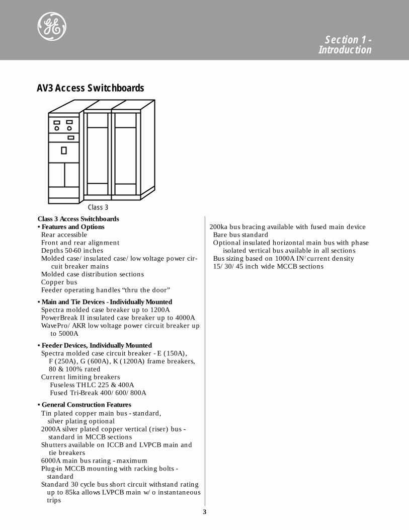
Class 3 Access Switchboards• Features and OptionsRear accessibleFront and rear alignmentDepths 50-60 inchesMolded case/insulated case/low voltage power cir-
cuit breaker mainsMolded case distribution sectionsCopper busFeeder operating handles “thru the door”
• Main and Tie Devices - Individually MountedSpectra molded case breaker up to 1200APowerBreak II insulated case breaker up to 4000AWavePro/AKR low voltage power circuit breaker up
to 5000A
• Feeder Devices, Individually MountedSpectra molded case circuit breaker - E (150A),
F (250A), G (600A), K (1200A) frame breakers,80 & 100% rated
Current limiting breakers Fuseless THLC 225 & 400AFused Tri-Break 400/600/800A
• General Construction FeaturesTin plated copper main bus - standard,
silver plating optional2000A silver plated copper vertical (riser) bus -
standard in MCCB sectionsShutters available on ICCB and LVPCB main and
tie breakers6000A main bus rating - maximumPlug-in MCCB mounting with racking bolts -
standardStandard 30 cycle bus short circuit withstand rating
up to 85ka allows LVPCB main w/o instantaneoustrips
200ka bus bracing available with fused main deviceBare bus standardOptional insulated horizontal main bus with phase
isolated vertical bus available in all sectionsBus sizing based on 1000A IN2 current density15/30/45 inch wide MCCB sections
Class 3
AV3 Access Switchboards
4
Section 1 - Introduction
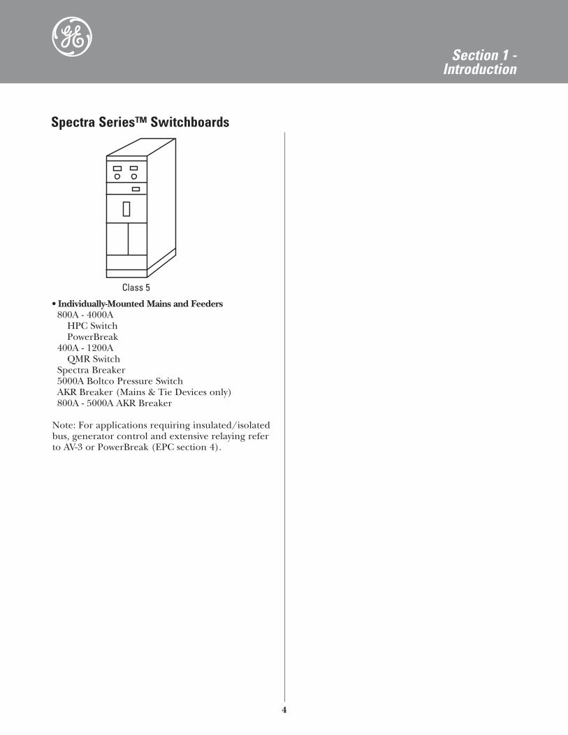
• Individually-Mounted Mains and Feeders800A - 4000A
HPC SwitchPowerBreak
400A - 1200AQMR Switch
Spectra Breaker5000A Boltco Pressure SwitchAKR Breaker (Mains & Tie Devices only)800A - 5000A AKR Breaker
Note: For applications requiring insulated/isolatedbus, generator control and extensive relaying referto AV-3 or PowerBreak (EPC section 4).
Class 5
Spectra Series™ Switchboards
5
Section 2 -Features and Characteristics
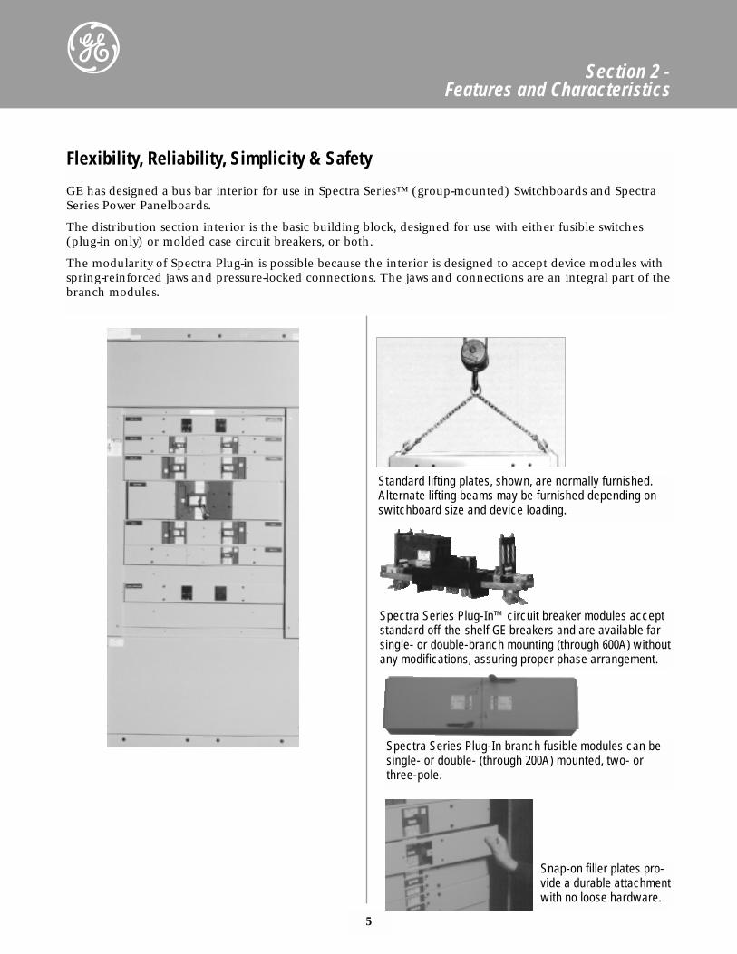
Flexibility, Reliability, Simplicity & Safety
GE has designed a bus bar interior for use in Spectra Series™ (group-mounted) Switchboards and SpectraSeries Power Panelboards.
The distribution section interior is the basic building block, designed for use with either fusible switches(plug-in only) or molded case circuit breakers, or both.
The modularity of Spectra Plug-in is possible because the interior is designed to accept device modules withspring-reinforced jaws and pressure-locked connections. The jaws and connections are an integral part of thebranch modules.
Standard lifting plates, shown, are normally furnished.Alternate lifting beams may be furnished depending onswitchboard size and device loading.
Spectra Series Plug-In™ circuit breaker modules acceptstandard off-the-shelf GE breakers and are available farsingle- or double-branch mounting (through 600A) withoutany modifications, assuring proper phase arrangement.
Spectra Series Plug-In branch fusible modules can besingle- or double- (through 200A) mounted, two- orthree-pole.
Snap-on filler plates pro-vide a durable attachmentwith no loose hardware.
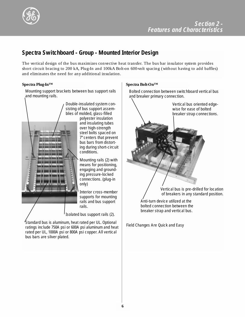
Bolted connection between switchboard vertical busand breaker primary connection.
Vertical bus oriented edge-wise for ease of bolted breaker strap connections.
Vertical bus is pre-drilled for location of breakers in any standard position.
Anti-turn device utilized at the bolted connection between the breaker strap and vertical bus.
Field Changes Are Quick and Easy
Mounting support brackets between bus support railsand mounting rails.
Double-insulated system con-sisting of bus support assem-blies of molded, glass-filled
polyester insulationand insulating tubesover high-strengthsteel bolts spaced on7" centers that preventbus bars from distort-ing during short-circuitconditions.
Mounting rails (2) withmeans for positioning,engaging and ground-ing pressure-lockedconnections. (plug-inonly)
Interior cross-membersupports for mountingrails and bus supportrails.
Isolated bus support rails (2).
Standard bus is aluminum, heat rated per UL. Optionalratings include 750A psi or 600A psi aluminum and heatrated per UL, 1000A psi or 800A psi copper. All verticalbus bars are silver plated.
6
Section 2 -Features and Characteristics
Spectra Switchboard - Group - Mounted Interior Design
The vertical design of the bus maximizes convective heat transfer. The bus bar insulator system providesshort circuit bracing to 200 kA, Plug-In and 100kA Bolt-on 600-volt spacing (without having to add baffles)and eliminates the need for any additional insulation.
Spectra Plug-In™ Spectra Bolt-On™
7
Section 2 -Features and Characteristics
The universal interior has made possible a family ofmodular components that provide the flexibilityunique to the Spectra Series™ product line. By utiliz-ing modular assembly and pressure-locked connec-tions to the interior, maintenance and tests are easierand faster.
This innovative design approach also facilitates fieldreconfiguration. Branch fusible units can be removedand circuit breaker units substituted.
Fusible switch and circuit breaker modules each con-sist of two assemblies: the protective device (fusibleswitch unit or molded case circuit breaker) and a con-necting mechanism. The connecting mechanisms arethe intermediate electrical/mechanical connectionsbetween the protective device and the bus structure inthe interior. The fusible connecting mechanism is inthe same housing as the fusible switch unit. The mold-ed case circuit breaker connecting mechanism is sepa-rate from the breakers and is designed to accept stan-dard GE circuit breakers.
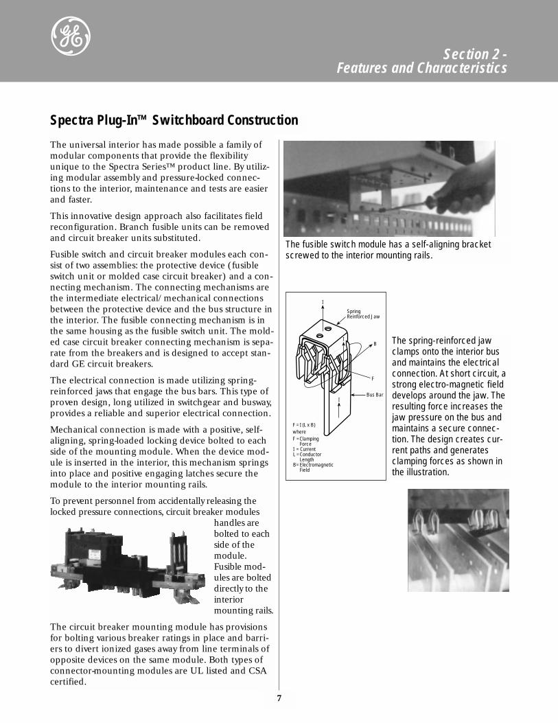
The electrical connection is made utilizing spring-reinforced jaws that engage the bus bars. This type ofproven design, long utilized in switchgear and busway,provides a reliable and superior electrical connection.
Mechanical connection is made with a positive, self-aligning, spring-loaded locking device bolted to eachside of the mounting module. When the device mod-ule is inserted in the interior, this mechanism springsinto place and positive engaging latches secure themodule to the interior mounting rails.
To prevent personnel from accidentally releasing thelocked pressure connections, circuit breaker modules
handles arebolted to eachside of themodule.Fusible mod-ules are bolteddirectly to theinteriormounting rails.
The circuit breaker mounting module has provisionsfor bolting various breaker ratings in place and barri-ers to divert ionized gases away from line terminals ofopposite devices on the same module. Both types ofconnector-mounting modules are UL listed and CSAcertified.
SpringReinforced Jaw
B
F
Bus Bar
F = I (L x B)whereF =Clamping
ForceI = CurrentL = Conductor
LengthB= Electromagnetic
Field
I
I
I The spring-reinforced jawclamps onto the interior busand maintains the electricalconnection. At short circuit, astrong electro-magnetic fielddevelops around the jaw. Theresulting force increases thejaw pressure on the bus andmaintains a secure connec-tion. The design creates cur-rent paths and generatesclamping forces as shown inthe illustration.
The fusible switch module has a self-aligning bracketscrewed to the interior mounting rails.
Spectra Plug-In™ Switchboard Construction
8
Section 2 -Features and Characteristics
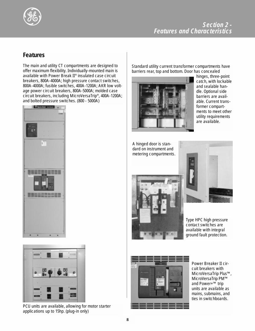
Features
The main and utility CT compartments are designed tooffer maximum flexibility. Individually-mounted main isavailable with Power Break II® insulated case circuitbreakers, 800A-4000A; high pressure contact switches,800A-4000A; fusible switches, 400A-1200A; AKR low volt-age power circuit breakers, 800A-5000A; molded casecircuit breakers, including MicroVersaTrip®, 400A-1200A;and bolted pressure switches. (800 - 5000A)
PCU units are available, allowing for motor starter applications up to 15hp. (plug-in only)
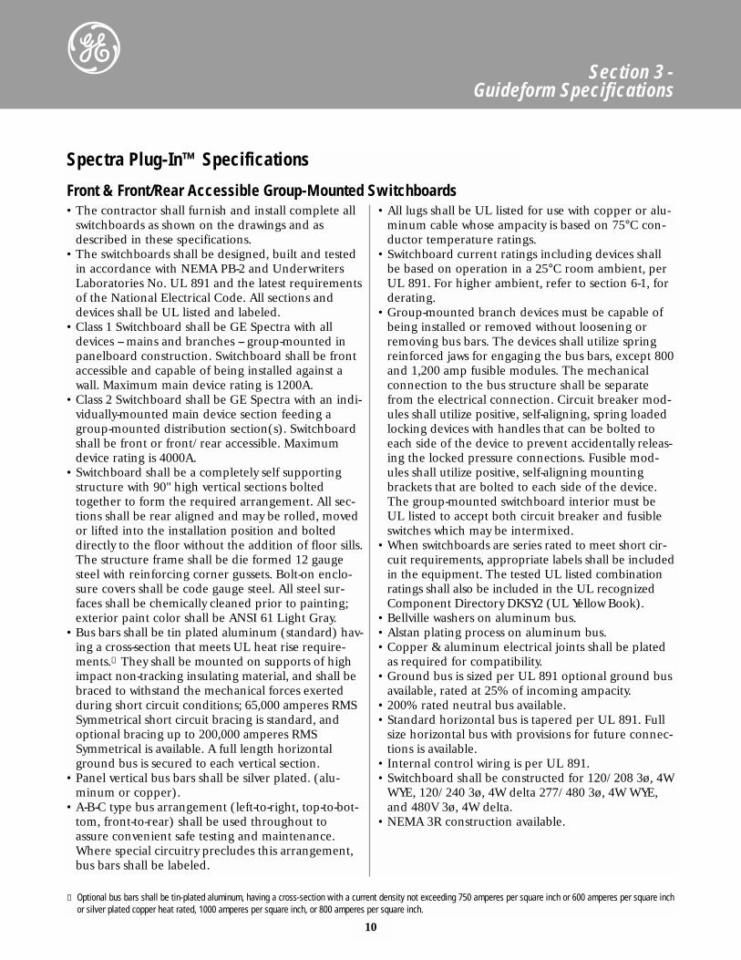
A hinged door is stan-dard on instrument andmetering compartments.
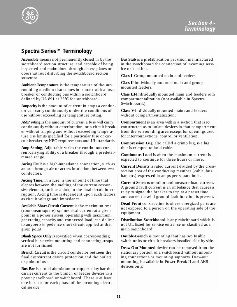
Power Breaker II cir-cuit breakers withMicroVersaTrip Plus™,MicroVersaTrip PM™and Power+™ tripunits are available asmains, submains, andties in switchboards.
Type HPC high pressurecontact switches areavailable with integralground fault protection.
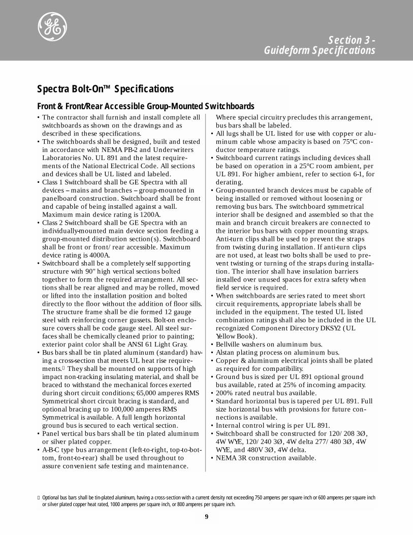
Standard utility current transformer compartments havebarriers rear, top and bottom. Door has concealed
hinges, three-pointcatch, with lockableand sealable han-dle. Optional sidebarriers are avail-able. Current trans-former compart-ments to meet otherutility requirementsare available.
9
Section 3 -Guideform Specifications
• The contractor shall furnish and install complete allswitchboards as shown on the drawings and asdescribed in these specifications.
• The switchboards shall be designed, built and testedin accordance with NEMA PB-2 and UnderwritersLaboratories No. UL 891 and the latest require-ments of the National Electrical Code. All sectionsand devices shall be UL listed and labeled.
• Class 1 Switchboard shall be GE Spectra with alldevices -- mains and branches -- group-mounted inpanelboard construction. Switchboard shall be frontand capable of being installed against a wall.Maximum main device rating is 1200A.
• Class 2 Switchboard shall be GE Spectra with anindividually-mounted main device section feeding agroup-mounted distribution section(s). Switchboardshall be front or front/rear accessible. Maximumdevice rating is 4000A.
• Switchboard shall be a completely self supportingstructure with 90" high vertical sections boltedtogether to form the required arrangement. All sec-tions shall be rear aligned and may be rolled, movedor lifted into the installation position and bolteddirectly to the floor without the addition of floor sills.The structure frame shall be die formed 12 gaugesteel with reinforcing corner gussets. Bolt-on enclo-sure covers shall be code gauge steel. All steel sur-faces shall be chemically cleaned prior to painting;exterior paint color shall be ANSI 61 Light Gray.
• Bus bars shall be tin plated aluminum (standard) hav-ing a cross-section that meets UL heat rise require-ments.① They shall be mounted on supports of highimpact non-tracking insulating material, and shall bebraced to withstand the mechanical forces exertedduring short circuit conditions; 65,000 amperes RMSSymmetrical short circuit bracing is standard, andoptional bracing up to 100,000 amperes RMSSymmetrical is available. A full length horizontalground bus is secured to each vertical section.
• Panel vertical bus bars shall be tin plated aluminumor silver plated copper.
• A-B-C type bus arrangement (left-to-right, top-to-bot-tom, front-to-rear) shall be used throughout toassure convenient safe testing and maintenance.
Where special circuitry precludes this arrangement,bus bars shall be labeled.
• All lugs shall be UL listed for use with copper or alu-minum cable whose ampacity is based on 75°C con-ductor temperature ratings.
• Switchboard current ratings including devices shallbe based on operation in a 25°C room ambient, perUL 891. For higher ambient, refer to section 6-1, forderating.
• Group-mounted branch devices must be capable ofbeing installed or removed without loosening orremoving bus bars. The switchboard symmetricalinterior shall be designed and assembled so that themain and branch circuit breakers are connected tothe interior bus bars with copper mounting straps.Anti-turn clips shall be used to prevent the strapsfrom twisting during installation. If anti-turn clipsare not used, at least two bolts shall be used to pre-vent twisting or turning of the straps during installa-tion. The interior shall have insulation barriersinstalled over unused spaces for extra safety whenfield service is required.
• When switchboards are series rated to meet shortcircuit requirements, appropriate labels shall beincluded in the equipment. The tested UL listedcombination ratings shall also be included in the ULrecognized Component Directory DKSY2 (ULYellow Book).
• Bellville washers on aluminum bus. • Alstan plating process on aluminum bus.• Copper & aluminum electrical joints shall be plated
as required for compatibility.• Ground bus is sized per UL 891 optional ground
bus available, rated at 25% of incoming ampacity.• 200% rated neutral bus available.• Standard horizontal bus is tapered per UL 891. Full
size horizontal bus with provisions for future con-nections is available.
• Internal control wiring is per UL 891.• Switchboard shall be constructed for 120/208 3Ø,
4W WYE, 120/240 3Ø, 4W delta 277/480 3Ø, 4WWYE, and 480V 3Ø, 4W delta.
• NEMA 3R construction available.
Spectra Bolt-On™ Specifications
Front & Front/Rear Accessible Group-Mounted Switchboards
① Optional bus bars shall be tin-plated aluminum, having a cross-section with a current density not exceeding 750 amperes per square inch or 600 amperes per square inchor silver plated copper heat rated, 1000 amperes per square inch, or 800 amperes per square inch.
10
Section 3 -Guideform Specifications
• The contractor shall furnish and install complete allswitchboards as shown on the drawings and asdescribed in these specifications.
• The switchboards shall be designed, built and testedin accordance with NEMA PB-2 and UnderwritersLaboratories No. UL 891 and the latest requirementsof the National Electrical Code. All sections anddevices shall be UL listed and labeled.
• Class 1 Switchboard shall be GE Spectra with alldevices -- mains and branches -- group-mounted inpanelboard construction. Switchboard shall be frontaccessible and capable of being installed against awall. Maximum main device rating is 1200A.
• Class 2 Switchboard shall be GE Spectra with an indi-vidually-mounted main device section feeding agroup-mounted distribution section(s). Switchboardshall be front or front/rear accessible. Maximumdevice rating is 4000A.
• Switchboard shall be a completely self supportingstructure with 90" high vertical sections boltedtogether to form the required arrangement. All sec-tions shall be rear aligned and may be rolled, movedor lifted into the installation position and bolteddirectly to the floor without the addition of floor sills.The structure frame shall be die formed 12 gaugesteel with reinforcing corner gussets. Bolt-on enclo-sure covers shall be code gauge steel. All steel sur-faces shall be chemically cleaned prior to painting;exterior paint color shall be ANSI 61 Light Gray.
• Bus bars shall be tin plated aluminum (standard) hav-ing a cross-section that meets UL heat rise require-ments.① They shall be mounted on supports of highimpact non-tracking insulating material, and shall bebraced to withstand the mechanical forces exertedduring short circuit conditions; 65,000 amperes RMSSymmetrical short circuit bracing is standard, andoptional bracing up to 200,000 amperes RMSSymmetrical is available. A full length horizontalground bus is secured to each vertical section.
• Panel vertical bus bars shall be silver plated. (alu-minum or copper).
• A-B-C type bus arrangement (left-to-right, top-to-bot-tom, front-to-rear) shall be used throughout toassure convenient safe testing and maintenance.Where special circuitry precludes this arrangement,bus bars shall be labeled.
• All lugs shall be UL listed for use with copper or alu-minum cable whose ampacity is based on 75°C con-ductor temperature ratings.
• Switchboard current ratings including devices shallbe based on operation in a 25°C room ambient, perUL 891. For higher ambient, refer to section 6-1, forderating.
• Group-mounted branch devices must be capable ofbeing installed or removed without loosening orremoving bus bars. The devices shall utilize springreinforced jaws for engaging the bus bars, except 800and 1,200 amp fusible modules. The mechanicalconnection to the bus structure shall be separatefrom the electrical connection. Circuit breaker mod-ules shall utilize positive, self-aligning, spring loadedlocking devices with handles that can be bolted toeach side of the device to prevent accidentally releas-ing the locked pressure connections. Fusible mod-ules shall utilize positive, self-aligning mountingbrackets that are bolted to each side of the device.The group-mounted switchboard interior must beUL listed to accept both circuit breaker and fusibleswitches which may be intermixed.
• When switchboards are series rated to meet short cir-cuit requirements, appropriate labels shall be includedin the equipment. The tested UL listed combinationratings shall also be included in the UL recognizedComponent Directory DKSY2 (UL Yellow Book).
• Bellville washers on aluminum bus. • Alstan plating process on aluminum bus.• Copper & aluminum electrical joints shall be plated
as required for compatibility.• Ground bus is sized per UL 891 optional ground bus
available, rated at 25% of incoming ampacity.• 200% rated neutral bus available.• Standard horizontal bus is tapered per UL 891. Full
size horizontal bus with provisions for future connec-tions is available.
• Internal control wiring is per UL 891.• Switchboard shall be constructed for 120/208 3ø, 4W
WYE, 120/240 3ø, 4W delta 277/480 3ø, 4W WYE,and 480V 3ø, 4W delta.
• NEMA 3R construction available.
Spectra Plug-In™ Specifications
Front & Front/Rear Accessible Group-Mounted Switchboards
① Optional bus bars shall be tin-plated aluminum, having a cross-section with a current density not exceeding 750 amperes per square inch or 600 amperes per square inchor silver plated copper heat rated, 1000 amperes per square inch, or 800 amperes per square inch.
11
Section 4 - Terminology
Accessible means not permanently closed in by theswitchboard section structure, and capable of beinginspected and maintained through access plates ordoors without disturbing the switchboard sectionstructure.
Ambient Temperature is the temperature of the sur-rounding medium that comes in contact with a fuse,breaker or conducting bus within a switchboarddefined by UL 891 as 25°C for switchboard.
Ampacity is the amount of current in amps a conduc-tor can carry continuously under the conditions ofuse without exceeding its temperature rating.
AMP rating is the amount of current a fuse will carrycontinuously without deterioration, or a circuit break-er without tripping and without exceeding tempera-ture rise limits specified for a particular fuse or cir-cuit breaker by NEC requirements and UL standards.
Amp Setting, Adjustable varies the continuous cur-rent-carrying ability of a breaker through a predeter-mined range.
Arcing Fault is a high-impedance connection, such asan arc through air or across insulation, between twoconductors.
Arcing Time, in a fuse, is the amount of time thatelapses between the melting of the current-respon-sive element, such as a link, to the final circuit inter-ruption. Arcing time is dependent upon such factorsas circuit voltage and impedance.
Available Short-Circuit Current is the maximum rms(root-mean-square) symmetrical current at a givenpoint in a power system, operating with maximumgenerating capacity and connected load, can deliverto any zero impedance short circuit applied at thatgiven point.
Blank Space Only is specified when correspondingvertical bus device mounting and connecting strapsare not furnished.
Branch Circuit is the circuit conductor between thefinal overcurrent device protection and the outletsor point of use.
Bus Bar is a solid aluminum or copper alloy bar thatcarries current to the branch or feeder devices in apower panelboard or switchboard. There is at leastone bus bar for each phase of the incoming electri-cal service.
Bus Stub is a prefabrication provision manufacturedin the switchboard for connection of incoming serv-ice or load bus.
Class I--Group mounted main and feeders.
Class II-Individually mounted main and groupmounted feeders.
Class III-Individually mounted main and feeders withcompartmentalization (not available in SpectraSwitchboard.)
Class V-Individually mounted mains and feederswithout compartmentalization.
Compartment is an area within a section that is soconstructed as to isolate devices in that compartmentfrom the surrounding area except for openings usedfor interconnections, control or ventilation.
Compression Lug, also called a crimp lug, is a lugthat is crimped to hold cable.
Continuous Load is when the maximum current isexpected to continue for three hours or more.
Current Density is rated current divided by the cross-section area of the conducting member (cable, busbar, etc.) expressed in amps per square inch.
Current Sensors monitor and measure load current.A ground fault current is an imbalance that causes arelay to signal the breaker to trip at a preset timeand current level if ground fault function is present.
Dead Front construction is where energized parts arenot exposed to a person on the operating side of theequipment.
Distribution Switchboard is any switchboard which isnot UL listed for service entrance or classified as amain switchboard.
Double-Branch is mounting that has two fusibleswitch units or circuit breakers installed side by side.
Draw-Out Mounted device can be removed from thestationary portion of a switchboard without unbolt-ing connections or mounting supports. Draw-outmounting is available in Power Break II and AKRdevices only.
Spectra Series™ Terminology
12
Section 4 - Terminology
Spectra Series™ Terminology
Depth Main DistributionSections
Front
Electrically Operated refers to an electrically operat-ed mechanism to remotely open and close a circuitbreaker. Typically used in automatic throwoverschemes and automatic control schemes.
Electrical Service or System is the conductors andequipment which delivers energy from the electricalsupply system to the wiring system of the premisesserved. The service or system consists of the numberof phases, number of wires, voltages and amps. Typeof service determines the number of poles on themain device, the number of poles valid for feeder orbranch devices and the minimum voltages for 1-, 2-,or 3-pole breakers and fusible switches.
Enclosure is a constructed case to protect personnelagainst contact with the enclosed equipment and toprotect the enclosed equipment against environmen-tal conditions.
Equipment Grounding is the interconnection andgrounding of electrical conduction material thateither encloses or is adjacent to power conductingcomponents.
Expansion Kit is an assembled kit that can beinstalled in an empty side of a double-branch fusibleswitch unit to create a new fusible switch unit Itincludes the handle, base plate, cover plate, loadbase and switch.
Feeder Circuit is all circuit conductors between theservice equipment or the source of a separatelyderived system and the final branch-circuit overcur-rent device.
Filler Mounts on side of fusible switch module, cir-cuit breaker module, or between side trims to coverthe front of the enclosure. The fillers plus trim com-prise the enclosure front around the installeddevices.
Fire Pump Disconnect serves only the code requiredfire pump. It must be connected ahead of any maindevice and sized to carry the locked rotor current ofthe fire pump per NFPA-20.
Frame Size is the physical size of the breaker with aspecific range of amp ratings. For example, anFrame breaker is available in ratings of 70 amps to225 amps in a 225 amp frame.
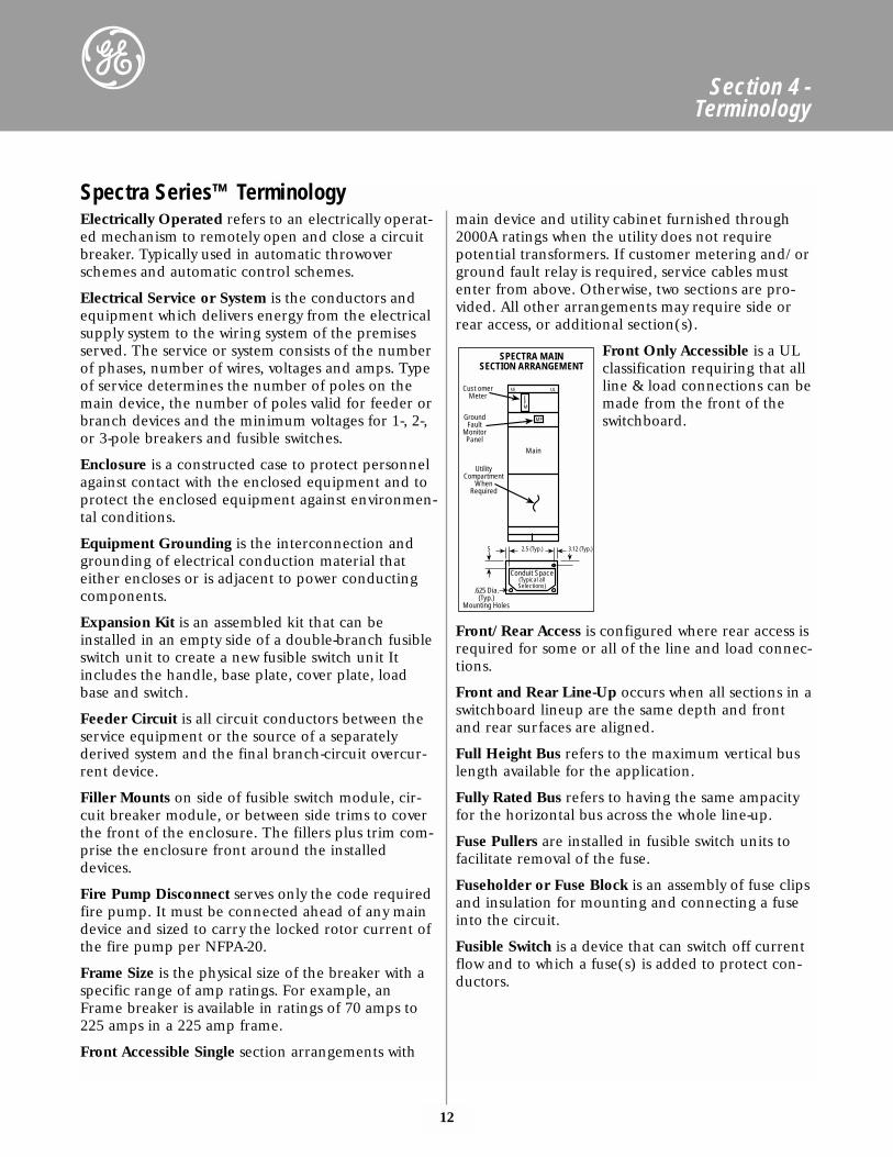
Front Accessible Single section arrangements with
main device and utility cabinet furnished through2000A ratings when the utility does not requirepotential transformers. If customer metering and/orground fault relay is required, service cables mustenter from above. Otherwise, two sections are pro-vided. All other arrangements may require side orrear access, or additional section(s).
Front Only Accessible is a ULclassification requiring that allline & load connections can bemade from the front of theswitchboard.
Front/Rear Access is configured where rear access isrequired for some or all of the line and load connec-tions.
Front and Rear Line-Up occurs when all sections in aswitchboard lineup are the same depth and frontand rear surfaces are aligned.
Full Height Bus refers to the maximum vertical buslength available for the application.
Fully Rated Bus refers to having the same ampacityfor the horizontal bus across the whole line-up.
Fuse Pullers are installed in fusible switch units tofacilitate removal of the fuse.
Fuseholder or Fuse Block is an assembly of fuse clipsand insulation for mounting and connecting a fuseinto the circuit.
Fusible Switch is a device that can switch off currentflow and to which a fuse(s) is added to protect con-ductors.
SPECTRA MAINSECTION ARRANGEMENT
Cust omerMeter
GroundFault
MonitorPanel
UtilityCompartment
WhenRequired
Main
.625 Dia.(Typ.)
Mounting Holes
Conduit Space(Typical allSelections)
5 2.5 (Typ.) 3.12 (Typ.)
SE UL
MP
EPM
13
Section 4 - Terminology
Spectra Series™ TerminologyGround Bus is horizontal bus which is electricallycontinuous with the switchboard housing for termi-nation of circuit ground conductor.
Ground Fault A fault condition created when anenergized conductor comes in contact with earthground or metallic structure, or causes an arc cur-rent to flow to ground.
Group (Panel)-Mounted device is one of a closelygrouped assembly of devices which is mounted on acommon base or mounting surface utilizing panel-board type construction. The total assembly is thenmounted in a switchboard combination or distribu-tion section.
Handle Lock Device is a mechanism to insert a lockto prevent operation of a circuit protective device.Most commonly used to lock device in the open oroff position for safety while performing mainte-nance.
Heat Rise is the maximum temperature a compo-nent in a switchboard can increase in temperatureover a defined amount 65°C per UL 891.
I2t is the measure of heat energy developed within acircuit, in which I2 stands for effective let-throughcurrent squared and t is time in seconds.
Individually Mounted means device which is notpanel-mounted and which may or may not beenclosed in its own compartment. Separated fromother devices to minimize undesired influence fromthem. (i.e. GE Class 3 and PowerBreak Switchboard).Power Break, HPC, AKR and BPS devices are individ-ually mounted.
Interior refers to the side rails, bus bars and insula-tion system that mounts in the enclosure. It is ener-gized through the main device (lugs, fusible switchor circuit breaker) and, in turn, energizes theinstalled circuit-protective devices (fusible switch orcircuit breaker).
Interrupting Rating is the highest rms-rated currenta fuse or breaker is intended to interrupt underspecified conditions.
Jaw refers to the metal parts that grip the interiorbus bar and conduct electricity to the module busbars. The jaws are spring-reinforced to provide ahighly reliable electrical connection.
Key Interlock, commonly called Kirk-keys, provides amechanical method to interlock two or more devicesutilizing a removable key which can only be insertedin one location at one time.
Line refers to the incoming (live) side of equipmentor device.
Load is the outgoing (switched) side of equipmentor device.
Lug is a device to terminate cables.
Magnetic Trip is synonymous with instantaneous tripand describes a tripping action with no intentionaltime delay. Current exceeding the magnetic triplevel will actuate the trip mechanism and open thebreaker contacts immediately.
Main Device is a single device that disconnects allungrounded switchboard conductors, other thancontrol power conductors when used, from the sup-ply bus.
Main Lug is the connecting means between theincoming service cable and the bus bar.
Mechanical Lug is a terminal with one or more wirebinding screws that are tightened to hold the con-ductor or cable.
Mimic Bus functionally displays internal buswork byapplying tape or plastic strip on equipment exterior.
NEMA Type 1 Enclosure - General Purpose Indoor isintended primarily to prevent accidental contact ofpersonnel with the enclosed equipment. In addition,it provides protection against falling dirt and is gas-keted with insect screens. The enclosure is intendedfor use indoors where it isn't exposed to unusualservice conditions, dripping or splashing water,steam or conductive dusts (NEMA PB2-5.02).
NEMA 3R Outdoor Enclosures are intended for usein wet locations or outdoors to protect the enclosedequipment against rain. They are sleet (ice) resistantbut are not dust, snow or sleet (ice) proof. If conduitconnections are provided, these enclosures shallhave a conduit hub or equivalent provision for water-tight connections at the conduit entrance when theconduit enters at a level higher than the lowest livepart. They have provisions for drainage.
14
Section 4 - Terminology
Overcurrent is any current in excess of the rated cur-rent of equipment or the ampacity of a conductorthat can result from an overload, a short circuit or aground fault.
Phase Failure Relay senses a loss of voltage in any ofthe three phases of a power system. It is used toalarm or trip an overcurrent device.
Plug-In Mounted device for line and load is one thatcan be plugged in to make electrical connections toa line and load bus bar. The device need not be self-supporting when withdrawn. It may be removedwhen switchboard is energized.
Pole The number of output terminals on a fusibleswitch or breaker that must be insulated and separat-ed from each other.
Power Panelboard is any panelboard that is not alighting or appliance panelboard as specified by ULand NEC and is not limited as to the number andrating of branch circuits, except for available spacingand physical size. The dead-front panelboard isaccessible from the front only.
Quick-make, Quick-break refers to the action ofmechanism, where the speed of the contacts inopening and closing a breaker or fusible switch isnot controlled by the operator.
Rear-Only Accessible switchboards have all incomingand outgoing cable or bus connections accessiblefrom the rear. Other connections may be front acces-sible.
Rear Line-Up Sections in a switchboard line-up aredifferent depths and rear surfaces are aligned.
Rejection Fuse and Clip is a combination of Class Rfuses and clips that will not accept fuses with a lowershort-circuit rating. This type of fuse and clip has amechanism that rejects standard NEMA Class Hfuses.
Reverse Feed The following devices have been testedand are listed for reverse feeding: Fixed trip moldedcase circuit breakers, MVT+, MVT PM and SpectraCircuit Breakers. Reverse feed devices may haveincoming (line) bottom and load top. They simplifybottom feed connections and minimize switchboarddepth. High pressure contact switches (HPC) can bespecified as bottom-fed devices. Power Break circuitbreakers with MVT+, MVT PM and Power+ program-mers can be reverse-fed without special ordering.
Rotor is a mechanism in a fusible switch unit thatmechanically ensures all switch blades open/closesimultaneously.
Selective Tripping is the application of circuit break-ers or fuses in series, so that, of the breakers or fusescarrying fault current, only the one nearest the faultopens and isolates the faulted circuit from the sys-tem.
Series-Connected Rated Panel means the UL Listedshort-circuit rating of the panel is equal to the IC rat-ing of the main protective device when properlyapplied with branch circuit protective device. Seesection 6.2 for further details.
Service Disconnect is a device or group of devicesthat disconnects all ungrounded load conductorsfrom the service (supply) conductors. The numberof service disconnects is limited to 6 per the NEC.
Service Entrance Equipment usually consists of cir-cuit breakers or switches and fuses and their acces-sories. It is located near the point of entrance of sup-ply conductors to a building and is intended to con-stitute the main control and means of cutoff for thesupply to the building. Service entrance equipmenthave a removable link between the neutral bus andground bus. The main device must also be barrieredfrom feeder devices.
Shunt Trip opens a circuit protection device byremote control.
Single-Branch A mounting module is a single devicemounted in a designated vertical space. Refers tobreakers or fused units.
Space and Busing for future when space and busingis only required for future inclusion of any specifieddevices, appropriate device supports, proper busconnections and corresponding vertical bus are fur-nished.
Standard (80%) and 100% Ratings Circuit breakersor fusible switches are to be applied at 80% of theirratings unless the overcurrent devices and the assem-blies in which they are mounted are listed for opera-tion at 100% of their ratings (NEC Articles 210-22(c), 220-3(a), 220-10(b), 384-16(c). Refer to list-ings for available 100% rated devices.
Spectra Series™ Terminology
15
Section 4 - Terminology
Stationary-Mounted device can be removed only byunbolting electrical connections and mounting sup-ports. Should only be removed when switchboard isdeenergized.
Tapered Bus on UL 89 is the downsizing of theBusway ampacity based diversity standards.
Thermal Trip protects against sustained overloads. Abimetallic element reacts time-wise in inverse propor-tion to the current. If a circuit is overloaded, heatfrom excessive current flow causes the bimetal tobend, actuating the trip mechanism to open thebreaker.
Time Delay is a term used by NEMA, ANSI and ULto denote a minimum opening time of 10 secondson an overload current five times the amp rating of acircuit breaker or Class H, K, J and R fuses. Timedelay is useful to let through momentary currentinrushes, such as in motor startups, without inter-rupting the circuit.
Trip Function is that portion of the breaker thatsenses fault conditions, controls the associated logicfunctions and initiates and powers the breaker tripdevice.
Trip Mechanisms are independent of manual controlhandles. The breaker will trip when a fault occurs,even if the handle is held in the "ON" position.
Under voltage release instantaneously trips thebreaker when voltage (control or line) drops to 30%-70% of nominal rating.
Voltage is electrical pressure that moves electronsthrough a conductor and is measured in volts.
Voltage Rating is the rms alternating current voltageat which a fuse or circuit breaker is designed to oper-ate.
X Value is an arbitrary vertical measurement of theusable mounting space on a panelboard for a fusibleswitch or breaker. X is equal to 1 3/8 inches(1.375"). Height of the interior is the sum of thehorizontally mounted, panel-mounted components.
Spectra Series™ Terminology
16
Section 5 - Sizing and Dimensions
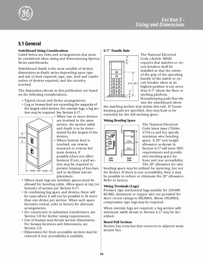
Switchboard Sizing ConsiderationsListed below are rules and arrangements that mustbe considered when sizing and dimensioning SpectraSeries switchboards.
Switchboard depth is the most variable of sectiondimensions as depth varies depending upon typeand size of feed required; type, size, feed and combi-nation of devices required; and the circuitryinvolved.
The dimensions shown in this publication are basedon the following considerations.
• Typical circuit and device arrangements.• Lug or busway feed not exceeding the ampacity of
the largest rated devices. For oversize lugs, a lug sec-tion may be required. See Section 6.17.
• When two or more devicesare involved in the samesection, the section widthand depth is to be deter-mined by the largest of thedevices.
• Where bottom feed isinvolved, use reversemounted or reverse fedmain devices, ifpossible.(does not affectfeeders) If not, a pull sec-tion may be required toprevent looping of bus barsand to facilitate barrierplacement.
• Where main lugs are involved, spaces must beallowed for bending cable. Allow space at top (orbottom) of section per Section 6.17.
• In combining lug space and devices, there willbe cases where it will not be possible to fit morethan one device per section. When such spacebecomes critical, refer to factory for alternatearrangements.
• For connection to substation transformers, seeSection 5-9 for further sizing requirements.
• Use of busway may dictate section dimensions.For busway locations and dimensions, seeSection 5.9.
• Dimensions for front accessible sections may bereduced if rear accessibility is available.
6'-7" Handle RuleThe National ElectricalCode (Article 380-8)requires that switches or cir-cuit breakers shall beinstalled so that the centerof the grip of the operatinghandle of the switch or cir-cuit breaker when in itshighest position is not morethan 6'-7" above the floor orworking platform.Housekeeping pads that ele-vate the switchboard above
the standing surface may violate this rule. If' house-keeping pads are specified, they may have to beextended for the full working space.
Wiring Bending SpaceThe National ElectricalCode latest issue (Tables373-6 (a and b)) specifyminimum wire bendingspace. A 20" unit heightallowance as shown inSection 6.17 will meet NECrequirements and providewire bending space forfront and rear accessibility.The 20" allowance for wire
bending space may be utilized for metering, but notfor devices. If there is rear accessibility, then it maybe possible to reduce or eliminate the 20" allowance.Refer to factory.
Wiring Terminals (Lugs)Pressure type mechanical lugs suitable for 250-600KCMIL aluminum or copper wire are provided forshort circuit ratings to l00,000A. Above 100,000A,compression type lugs may be required.
When oversize lugs are required, a lug section withminimum width shown in Section 6.17 may be fur-nished.
Bused Pull SectionsSection has cross bus that connects to adjacent mainsection bus.
5.1 General
Unit Hgt
Width Depth
6’-6” (78”)
3”
3”
Main Lugs
3”
3”
Utility
Main
20”
28”
Main
Utility
SideView
FrontView
90”
17
Section 5 - Sizing and Dimensions
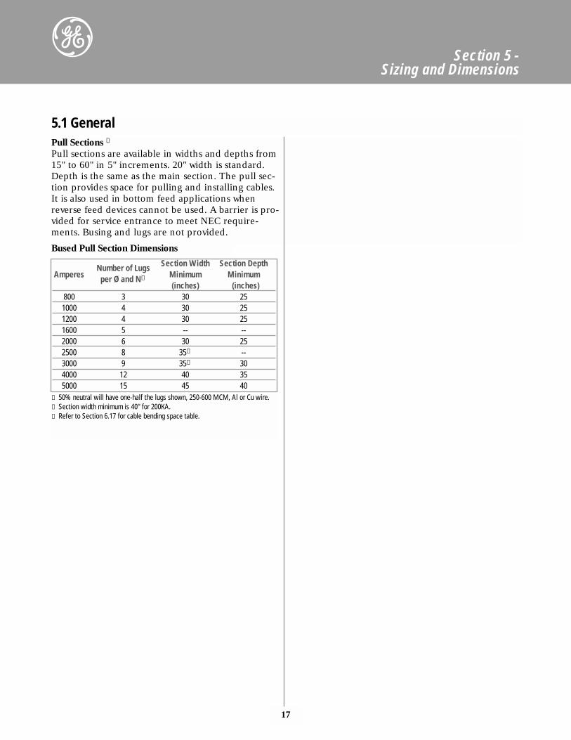
Pull Sections ➂Pull sections are available in widths and depths from15" to 60" in 5" increments. 20" width is standard.Depth is the same as the main section. The pull sec-tion provides space for pulling and installing cables.It is also used in bottom feed applications whenreverse feed devices cannot be used. A barrier is pro-vided for service entrance to meet NEC require-ments. Busing and lugs are not provided.
Number of Lugs Section Width Section DepthAmperes per Ø and N① Minimum Minimum
(inches) (inches)800 3 30 251000 4 30 251200 4 30 251600 5 -- --2000 6 30 252500 8 35➁ --3000 9 35➁ 304000 12 40 355000 15 45 40
① 50% neutral will have one-half the lugs shown, 250-600 MCM, Al or Cu wire.➁ Section width minimum is 40" for 200KA.➂ Refer to Section 6.17 for cable bending space table.
Bused Pull Section Dimensions
5.1 General
18
Section 5 - Sizing and Dimensions
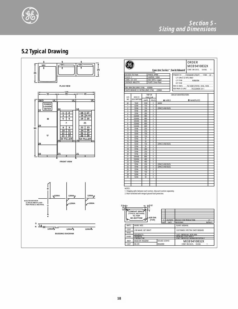
5.2 Typical Drawing
35
5BC 5BC 5BC
25
PLAN VIEW
12535 45 45
90
SEO UL UL UL
24
M
U
28
16
16
POWERLEADERMETER 14 14
21211 2 3
2465
31
7
8 91113
1012
15144X FILLER
49 33X 49 33X
17BLANK
20191816
21
22 232527
2426
29285X FILLER
FRONT VIEW
1200A 1200A1200A
1200A 1000A
M
U
G
N1200A 1200A 1200A
BUSSING DIAGRAM
(4) 250-600 MCM(1-HOLE) MECH LUGSPER PHASE & NEUTRAL 2.5 3.12
.625 DIA(TYP)
CONDUIT SPACE(TYPICAL SECTIONS)
TC-TOPBC-BOTTOM
Spectra Series™ Switchboard
ACCESS TO: Front PHASE: 3P4WCLASS: 2 AMPERE: 1200ALABEL: U/L SEO BUS MATL: CopperVOLTAGE: 480/277V PLATE: Silver Plate
BUS BRACING (RMS SYM) 65000ASWITCHBOARD SC RATING (RMS SYM) 22000A
CKT. DEVI CETRIP OR CIRCUIT IDENTIFICATION
NO. DESCRIPTIONFUSE CLIP
AMPS POLES LABELS NAMEPLATESM TK4V 1200 3 MAIN1 SEHA 150 32 SEHA 150 3 (SPACE AND BUS)3 SFHA 200 34 SFHA 200 35 SGHA4 400 36 SGHA4 400 37 SKHA8 800 38 SGHA6 600 39 SGHA6 600 310 SFHA 250 311 SFHA 250 312 SEHA 150 313 SEHA 150 314 SEHA 50 315 SEHA 50 316 SEHA 150 3 (SPACE AND BUS)17 SEHA 50 318 SFHA 200 319 SFHA 250 320 SFHA 250 321 SKHA8 800 322 SGHA4 400 323 SGHA4 400 324 SFHA 250 3 (SPACE AND BUS)25 SFHA 250 3 (SPACE AND BUS)26 SEHA 150 327 SEHA 150 328 SEHA 50 329 SEHA 50 3
NOTES:1. Shipping splits between each section, ship each section separately.2. Main furnished with integral ground fault protection.
1 03/29/93 RELEASE FOR PRODUCTION JYNO DATE REVISIONS INITIALS
MAT’L MARK: MDS PLANT: MEBANE
COST JOB NAME: GET DRAFT CUSTOMER: SPECTRA SWITCHBOARDPANEL
ARCHITECTS: CUST. ORDER NO. 3678-3456SWBD. ENGINEER: REQN NO: 37357 4935-1
CONTRACTOR: ED&C ORDER NO: MEB9410932XITEM 1INSP. MADE BY: ROGERW ISSUED 3/29/93
CUST. REL BY: ROGERW CONT. ON SH.FL. SH.NO. 1
POWER CO. _ __STANDARD UTILITY_ _ CODE _ ZZ _C/T SPACE & MTG ONLYC/T TYPE WINDOW P/T TYPE
PER CE DWG 75C143813 PV101, 101A, 101B PER PWR CO SPEC 75C323045A SH 1
MEB9410832X
ORDERMEB9410832XCONT. ON SH.FL. SH.NO. 1
19
Section 5 - Sizing and Dimensions
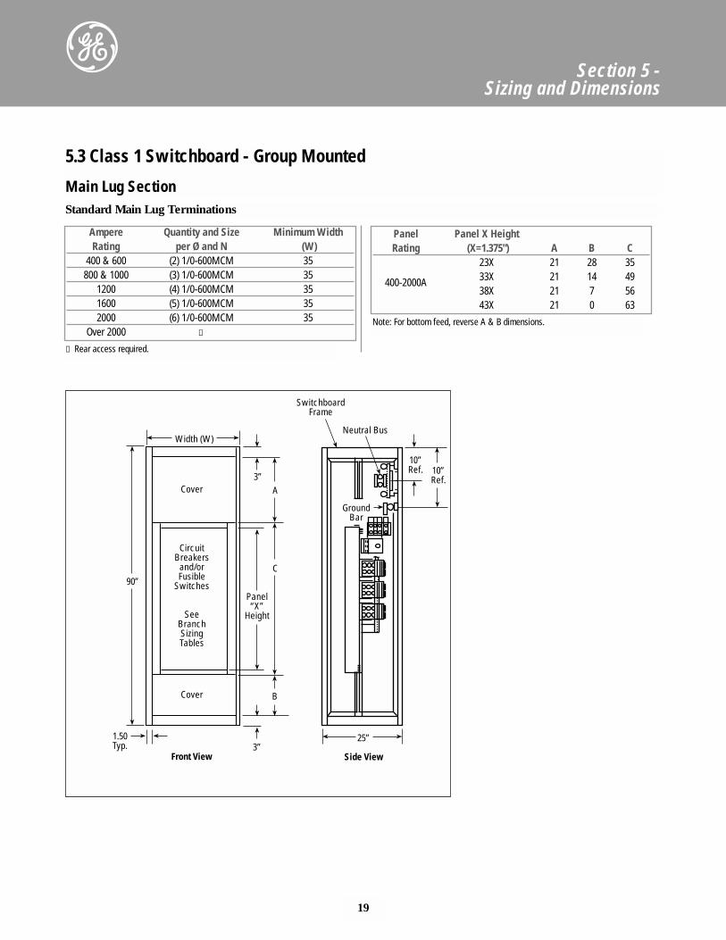
Ampere Quantity and Size Minimum WidthRating per Ø and N (W)
400 & 600 (2) 1/0-600MCM 35800 & 1000 (3) 1/0-600MCM 35
1200 (4) 1/0-600MCM 351600 (5) 1/0-600MCM 352000 (6) 1/0-600MCM 35
Over 2000 ①
Panel Panel X HeightRating (X=1.375") A B C
23X 21 28 35
400-2000A 33X 21 14 4938X 21 7 5643X 21 0 63
① Rear access required.
Note: For bottom feed, reverse A & B dimensions.
5.3 Class 1 Switchboard - Group Mounted
Main Lug SectionStandard Main Lug Terminations
Width (W)
Cover3”
90”
CircuitBreakers
and/orFusible
Switches
SeeBranchSizingTables
Panel“X”
Height
Cover
1.50Typ. 3”
Front View
A
C
B
SwitchboardFrame
Neutral Bus
GroundBar
25”
Side View
10”Ref. 10”
Ref.
20
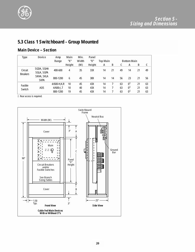
Section 5 - Sizing and Dimensions
Type Device Amp Main Min. PanelRange "X" Width "X" Top Main Bottom Main
Height (W) Height A B C A B C
Circuit SGDA, SGHA 400-600 4 35 33X 14 21 49 14 21 49Breakers SGLA, SGPA
SKHA, SKLA800-1200 6 45 38X 14 14 56 23 21 56
SKPA
Fusible 4/600-H,K,R 10 45 43X 14 7 63 0① 21 63
Switch ADS 4/600-J,T 10 40 43X 14 7 63 0① 21 63800-1200 19 45 43X 14 7 63 0① 21 63
① Rear access is required.
5.3 Class 1 Switchboard - Group Mounted
Main Device – Section
Width (W)
Cover 3”
90”
Main
Circuit Breakersand/or
Fusible Switches
See BranchSizing Tables
Panel“X”
Height
Cover
1.50Typ. 3”
Front View
Cable Fed Main DevicesWith or Without CT’s
A
C
B
SwitchboardFrame
Neutral Bus
GroundBar
25”
Side View
21
Section 5 - Sizing and Dimensions
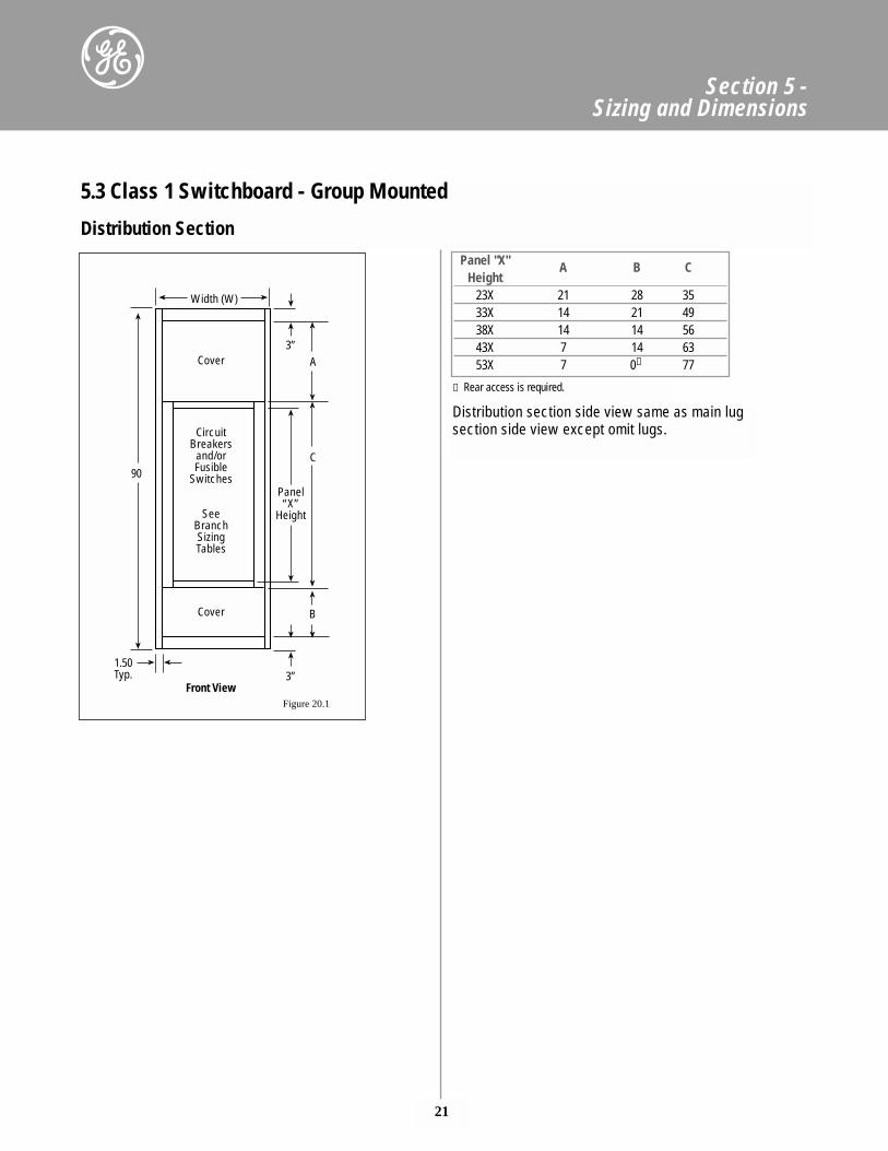
Panel "X" A B CHeight
23X 21 28 3533X 14 21 4938X 14 14 5643X 7 14 6353X 7 0① 77
① Rear access is required.
Distribution section side view same as main lugsection side view except omit lugs.
5.3 Class 1 Switchboard - Group Mounted
Distribution Section
Width (W)
Cover3”
90
CircuitBreakers
and/orFusible
Switches
SeeBranchSizingTables
Panel“X”
Height
Cover
1.50Typ. 3”
Front View
A
C
B
Figure 20.1
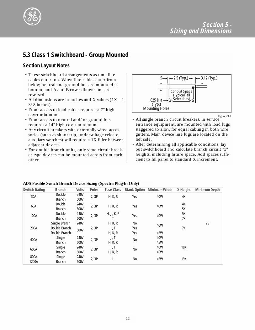
ADS Fusible Switch Branch Device Sizing (Spectra Plug-In Only)Switch Rating Branch Volts Poles Fuse Class Blank Option Minimum Width X Height Minimum Depth
30A Double 240V 2, 3P H, K, R Yes 40W 4XBranch 600V
60A Double 240V 2, 3P H, K, R Yes 40W 4XBranch 600V 5X
100A Double 240V 2, 3P H, J, K, R Yes 40W 5XBranch 600V T 7X
Single Branch 240V H, K, R No 40W 25200A Double Branch 600V 2, 3P J, T Yes 7X
Double Branch H, K, R Yes 45W
400A Single 240V 2, 3P J, T No 40WBranch 600V H, K, R 45W
600A Single 240V 2, 3P J, T No 40W 10XBranch 600V H, K, R 45W
800A Single 240V 2, 3P L No 45W 19X1200A Branch 600V
22
Section 5 - Sizing and Dimensions
• These switchboard arrangements assume linecables enter top. When line cables enter frombelow, neutral and ground bus are mounted atbottom, and A and B cover dimensions arereversed.
• All dimensions are in inches and X values (1X = 13/8 inches).
• Front access to load cables requires a 7" highcover minimum.
• Front access to neutral and/or ground busrequires a 14" high cover minimum.
• Any circuit breakers with externally wired acces-sories (such as shunt trip, undervoltage release,auxiliary switches) will require a 1X filler betweenadjacent devices.
• For double branch units, only same circuit break-er type devices can be mounted across from eachother.
• All single branch circuit breakers, in serviceentrance equipment, are mounted with load lugsstaggered to allow for equal cabling in both wiregutters. Main device line lugs are located on theleft side.
• After determining all applicable conditions, layout switchboard and calculate branch circuit "x"heights, including future space. Add spaces suffi-cient to fill panel to standard X increment.
5.3 Class 1 Switchboard - Group Mounted
Section Layout Notes
5 2.5 (Typ.) 3.12 (Typ.)
.625 Dia.(Typ.)
Mounting Holes
Conduit Space(Typical allSelections)
Figure 21.1
23
Section 5 - Sizing and Dimensions
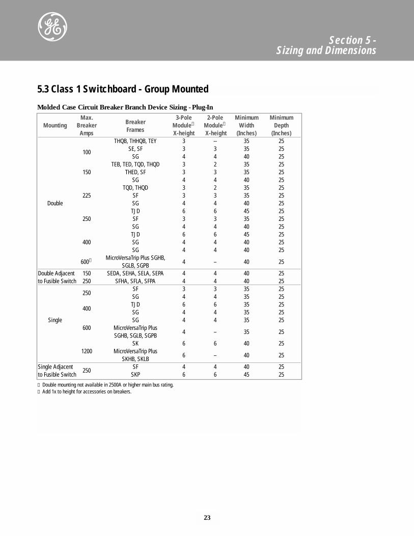
Molded Case Circuit Breaker Branch Device Sizing - Plug-InMax. 3-Pole 2-Pole Minimum Minimum
Mounting Breaker Breaker Module➁ Module➁ Width DepthAmps Frames X-height X-height (Inches) (Inches)
THQB, THHQB, TEY 3 -- 35 25
100 SE, SF 3 3 35 25SG 4 4 40 25
TEB, TED, TQD, THQD 3 2 35 25150 THED, SF 3 3 35 25
SG 4 4 40 25TQD, THQD 3 2 35 25
225 SF 3 3 35 25Double SG 4 4 40 25
TJD 6 6 45 25250 SF 3 3 35 25
SG 4 4 40 25TJD 6 6 45 25
400 SG 4 4 40 25SG 4 4 40 25
600① MicroVersaTrip Plus SGHB,4 – 40 25
SGLB, SGPBDouble Adjacent 150 SEDA, SEHA, SELA, SEPA 4 4 40 25to Fusible Switch 250 SFHA, SFLA, SFPA 4 4 40 25
250SF 3 3 35 25SG 4 4 35 25
400TJD 6 6 35 25SG 4 4 35 25
Single SG 4 4 35 25600 MicroVersaTrip Plus
4 – 35 25SGHB, SGLB, SGPB
SK 6 6 40 251200 MicroVersaTrip Plus
6 – 40 25SKHB, SKLB
Single Adjacent SF 4 4 40 25to Fusible Switch
250SKP 6 6 45 25
5.3 Class 1 Switchboard - Group Mounted
① Double mounting not available in 2500A or higher main bus rating.➁ Add 1x to height for accessories on breakers.
24
Section 5 - Sizing and Dimensions
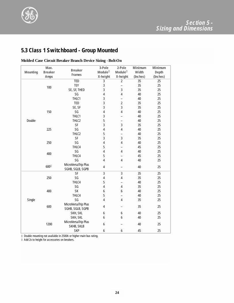
5.3 Class 1 Switchboard - Group Mounted
Molded Case Circuit Breaker Branch Device Sizing - Bolt-On
Max. 3-Pole 2-Pole Minimum MinimumMounting Breaker Breaker Module➁ Module➁ Width Depth
Amps Frames X-height X-height (Inches) (Inches) TED 3 2 35 25
100 TEY 3 – 35 25SE, SF, THED 3 3 35 25
SG 4 4 40 25THLC1 3 – 40 25
TED 3 2 35 25SE, SF 3 3 35 25
150 SG 4 4 40 25THLC1 3 – 40 25
Double THLC2 5 – 40 25SF 3 3 35 25
225 SG 4 4 40 25THLC2 5 – 40 25
SF 3 3 35 25250 SG 4 4 40 25
THLC4 5 – 45 25
400SG 4 4 40 25
THLC4 5 – 45 25SG 4 4 40 25
600① MicroVersaTrip Plus4 – 40 25
SGHB, SGLB, SGPBSF 3 3 35 25
250 SG 4 4 35 25THLC4 5 – 40 25
SG 4 4 35 25400 SK 6 6 40 25
THLC4 5 – 40 25Single SG 4 4 35 25
600MicroVersaTrip Plus
4 – 35 25SGHB, SGLB, SGPB
SKH, SKL 6 6 40 25SKH, SKL 6 6 40 25
1200MicroVersaTrip Plus
6 – 40 25SKHB, SKLB
SKP 6 6 45 25① Double mounting not available in 2500A or higher main bus rating.➁ Add 2x to height for accessories on breakers.
25
Section 1 - Introduction
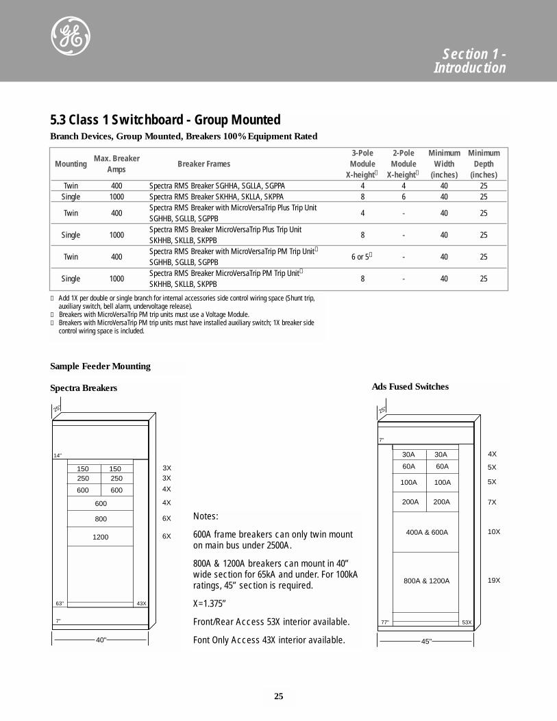
Branch Devices, Group Mounted, Breakers 100% Equipment Rated
Spectra Breakers Ads Fused Switches
Sample Feeder Mounting
3-Pole 2-Pole Minimum MinimumMounting
Max. Breaker Breaker Frames Module Module Width Depth
AmpsX-height① X-height① (inches) (inches)
Twin 400 Spectra RMS Breaker SGHHA, SGLLA, SGPPA 4 4 40 25Single 1000 Spectra RMS Breaker SKHHA, SKLLA, SKPPA 8 6 40 25
Twin 400Spectra RMS Breaker with MicroVersaTrip Plus Trip Unit SGHHB, SGLLB, SGPPB
4 - 40 25
Single 1000Spectra RMS Breaker MicroVersaTrip Plus Trip Unit SKHHB, SKLLB, SKPPB
8 - 40 25
Twin 400Spectra RMS Breaker with MicroVersaTrip PM Trip Unit➁
SGHHB, SGLLB, SGPPB6 or 5➂ - 40 25
Single 1000Spectra RMS Breaker MicroVersaTrip PM Trip Unit➁
SKHHB, SKLLB, SKPPB8 - 40 25
① Add 1X per double or single branch for internal accessories side control wiring space (Shunt trip,auxiliary switch, bell alarm, undervoltage release).
➁ Breakers with MicroVersaTrip PM trip units must use a Voltage Module.➂ Breakers with MicroVersaTrip PM trip units must have installed auxiliary switch; 1X breaker side
control wiring space is included.
5.3 Class 1 Switchboard - Group Mounted
Notes:
600A frame breakers can only twin mounton main bus under 2500A.
800A & 1200A breakers can mount in 40”wide section for 65kA and under. For 100kAratings, 45” section is required.
X=1.375”
Front/Rear Access 53X interior available.
Font Only Access 43X interior available.
150
14"
25"
43X63"
7"
150250 250
600600
600
800
1200
3X3X
4X
4X
6X
6X
40"
30A
7"
25"
53X77"
30A
60A 60A
100A100A
200A 200A
400A & 600A
800A & 1200A
4X
5X
5X
7X
19X
10X
45"
26
Section 5 - Sizing and Dimensions
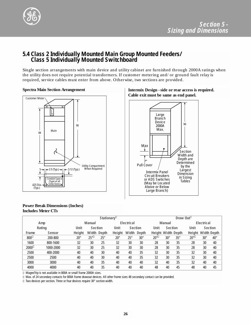
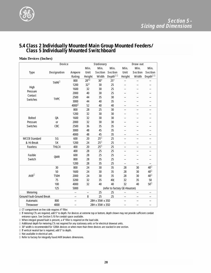
5.4 Class 2 Individually Mounted Main Group Mounted Feeders/Class 5 Individually Mounted Switchboard
Single section arrangements with main device and utility cabinet are furnished through 2000A ratings whenthe utility does not require potential transformers. If customer metering and/or ground fault relay isrequired, service cables must enter from above. Otherwise, two sections are provided.
5 2.5 (Typ.) 3.12 (Typ.)
.625 Dia.(Typ.)
Conduit Space(Typical allSelections)
Utility CompartmentWhen Required
Customer Meter
EPM
ULSE
84
90
Main
SectionWidth andDepth are
Determinedby the
LargestDimension
in SizingTables
LargeBranchDevice2000AMax.
7" Pull Cover
Max
90
Intermix PanelCircuit Breakersor ADS Swtiches(May be LocatedAbove or BelowLarge Branch)
Spectra Main Section Arrangement Intermix Design - side or rear access is required. Cable exit must be same as end panel.
Stationary➂ Draw Out➁
Amp Manual Electrical Manual ElectricalRating Unit Section Unit Section Unit Section Unit Section
Frame Sensor Height Width Depth Height Width Depth Height Width Depth Height Width Depth800➁ 200-800 20" 25"➂ 25" 20" 25" 30" 20"➂ 30" 35" 20"➂ 30" 40"1600 800-1600 32 30 25 32 30 30 28 30 35 28 30 40
2000➁ 1000-2000 32 30 25 32 30 30 28 30 35 28 30 402500 400-2000 40 40 30 40 40 35 32 30 35 32 30 402500 2500 40 40 30 40 40 35 32 30 35 32 30 403000 3000 40 40 35 40 40 40 32 40 35 32 40 404000 4000 40 40 35 40 40 40 48 40 45 48 40 45
Power Break Dimensions (Inches)Includes Meter CTs
① MagneTrip is not available in 800A or small frame 2000A sizes.➁ Max. of 24 secondary contacts for 800A frame drawout devices. All other frame sizes 48 secondary contact can be provided.➂ Two devices per section. Three or four devices require 30” section width.
27
Section 5 - Sizing and Dimensions
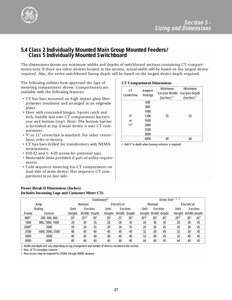
5.4 Class 2 Individually Mounted Main Group Mounted Feeders/Class 5 Individually Mounted Switchboard
Stationary① Draw Out① ➁ ➂
Amp Manual Electrical Manual ElectricalRating Unit Section Unit Section Unit Section Unit Section
Frame Sensor Height Width Depth Height Width Depth Height Width Depth Height Width Depth800➁ 200, 400, 800 20" 25"① 30" 20" 25" 30" 20"① 30" 45" 20"① 30" 45"1600 800, 1000, 1600 20 30 35 20 30 35 20 30 45 20 30 45
2000➁ 2000 20 30 35 20 30 35 20 30 45 20 30 452500 1000, 2000, 2500 40 40 40 40 40 40 32 30 45 32 30 453000 3000 40 40 40 40 40 40 32 40 45 32 40 454000 4000 40 40 40 40 40 40 44 40 45 44 40 45
Power Break II Dimensions (Inches)Includes Incoming Lugs and Customer Meter CTs
① Width and depth will vary depending on lug arrangement and number of devices included in the section.➁ Max. of 72 secondary contacts.➂ Rear access may be required for 2500A through 4000A drawout.
The following utilities have approved the type ofmetering compartment shown. Compartments areavailable with the following features:
• CT bus bars mounted on high impact glass fiberpolyester insulation and arranged in an edgewiseplane.
• Door with concealed hinges, 3-point catch andlock, handle seal over CT compartment barriersrear and bottom (top). Note: The bottom barrieris furnished at top if main device is over CT com-partment.
• 9" or 11" centerline is standard. For other center-lines, refer to factory.
• CT bus bars drilled for transformers with NEMAterminations.
• #10-32 and 1/4-20 screws for potential taps.• Removable links provided if part of utility require-
ments.• Cold sequence metering has CT compartment on
load side of main device. Hot sequence CT com-partment is on line side.
CT Ampere Minimum Minimum
Centerline Ratings Section Width Section Depth(inches) ① (inches) ①
6008001000
9" 1200 35 35or 1600
11" 2000250030004000 40 40
① Add 5" to depth when busway entrance is required.
The dimensions shown are minimum widths and depths of switchboard sections containing CT compart-ments only. If there are other devices located in the section, actual width will be based on the largest devicerequired. Also, the entire switchboard lineup depth will be based on the largest device depth required.
CT Compartment Dimensions
28
Section 5 - Sizing and Dimensions
Device Stationary Draw outMin. Min. Min. Min. Min. Min.
Type Designation Ampere Unit Section Section Unit Section Section Rating Height Width Depth➁➅ Height Width Depth➁➅
THPR➆ 800 28"① 30" 25" -- -- --1200 32① 30 25 -- -- --
High 1600 32 30 25 -- -- --Pressure 2000 40 30 25 -- -- --Contact
THPC 2500 44 35 30 -- -- --Switches 3000 44 40 35 -- -- --
4000➂ 52 40 40 -- -- --800 28 25 30 -- -- --1200 32 30 30 -- -- --
Bolted QA 1600 32 30 30 -- -- --Pressure or 2000 32 30 30 -- -- --Switches CBC 2500 36 35 35 -- -- --
3000 48 45 35 -- -- --4000 48 45 35 -- -- --
MCCB Standard SG 600 20 25⑤ 25 -- -- --& Hi-Break SK 1200 24 25⑤ 25 -- -- --Fuseless THLC4 400 20 25⑤ 25 -- -- --
400 28 25 25 -- -- --Fusible QMR 600 28 25 25 -- -- --Switch 800 28 35 25 -- -- --
1200 28 35 25 -- -- --30 800 24 30 35 28 30 40➃
50 1600 24 30 35 28 30 40➃
AKR➇ T50H 2000 24 30 35 28 30 40➃
75 3200 32 35 40( 32 35 50100 4000 32 40 40 32 40 50➃
125 5000 (refer to factory GE-Houston)Metering -- -- 25 25 -- -- --
Ground Fault-Ground Break -- 8 25 25 -- -- --Automatic 800 -- 28H x 35W x 35D -- -- --Throwover 4000 -- 28H x 35W x 35D -- -- --
① CT compartment on line side requires 4" filler.➁ If metering CTs are required, add 5" to depth. For devices at extreme top or bottom, depth shown may not provide sufficient conduit
entrance space. See Section 5.10 for conduit space available.➂ When integral ground fault is present, a 4" filler is required on the load side.➃ Additional depth for metering CTs not required for any stationary units or for electrical drawout units.⑤ 30" width is recommended for 1200A devices or when more than three devices are stacked in one section.➅ If vertical neutral bar is required, add 5" to depth.➆ Not available in electrical unit.➇ Refer to factory for integrally fused AKR breakers dimensions.
5.4 Class 2 Individually Mounted Main Group Mounted Feeders/Class 5 Individually Mounted Switchboard
Main Devices (Inches)
29
Section 5 - Sizing and Dimensions
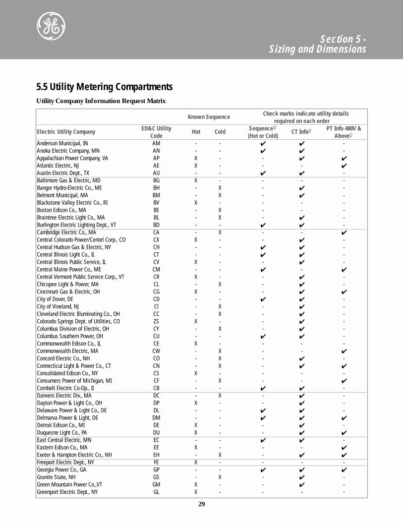
Utility Company Information Request Matrix
Known Sequence Check marks indicate utility details required on each order
Electric Utility Company ED&C Utility Hot Cold Sequence①CT Info➁ PT Info 480V &
Code (Hot or Cold) Above➁
Anderson Municipal, IN AM - - ✔ ✔ -Anoka Electric Company, MN AN - - ✔ ✔ -Appalachian Power Company, VA AP X - - ✔ ✔
Atlantic Electric, NJ AE X - - - ✔
Austin Electric Dept., TX AU - - ✔ ✔ -Baltimore Gas & Electric, MD BG X - - - -Bangor Hydro-Electric Co., ME BH - X - ✔ -Belmont Municipal, MA BM - X - ✔ -Blackstone Valley Electric Co., RI BV X - - - -Boston Edison Co., MA BE - X - - -Braintree Electric Light Co., MA BL - X - ✔ -Burlington Electric Lighting Dept., VT BD - - ✔ ✔ -Cambridge Electric Co., MA CA - X - - ✔
Central Colorado Power/Centel Corp., CO CX X - - ✔ -Central Hudson Gas & Electric, NY CH - - ✔ ✔ -Central Illinois Light Co., IL CT - - ✔ ✔ -Central Illinois Public Service, IL CV X - - ✔ -Central Maine Power Co., ME CM - - ✔ - ✔
Central Vermont Public Service Corp., VT CR X - - ✔ -Chicopee Light & Power, MA CL - X - ✔ -Cincinnati Gas & Electric, OH CG X - - ✔ ✔
City of Dover, DE CD - - ✔ ✔ -City of Vineland, NJ Cl - X - ✔ -Cleveland Electric Illuminating Co., OH CC - X - ✔ -Colorado Springs Dept. of Utilities, CO ZS X - - ✔ -Columbus Division of Electric, OH CY - X - ✔ -Columbus Southern Power, OH CU - - ✔ ✔ -Commonwealth Edison Co., IL CE X - - - -Commonwealth Electric, MA CW - X - - ✔
Concord Electric Co., NH CO - X - ✔ -Connecticut Light & Power Co., CT CN - X - ✔ ✔
Consolidated Edison Co., NY CS X - - - -Consumers Power of Michigan, MI CF - X - - ✔
Cornbelt Electric Co-Op., II CB - - ✔ ✔ -Danvers Electric Div., MA DC - X - ✔ -Dayton Power & Light Co., OH DP X - - ✔ -Delaware Power & Light Co., DE DL - - ✔ ✔ -Delmarva Power & Light, DE DM - - ✔ ✔ ✔
Detroit Edison Co., MI DE X - - ✔ -Duquesne Light Co., PA DU X - - ✔ ✔
East Central Electric, MN EC - - ✔ ✔ -Eastern Edison Co., MA EE X - - - ✔
Exeter & Hampton Electric Co., NH EH - X - ✔ ✔
Freeport Electric Dept., NY FE X - - - -Georgia Power Co., GA GP - - ✔ ✔ ✔
Granite State, NH GS - X - ✔ -Green Mountain Power Co.,VT GM X - - ✔ -Greenport Electric Dept., NY GL X - - - -
5.5 Utility Metering Compartments
30
Section 5 - Sizing and Dimensions
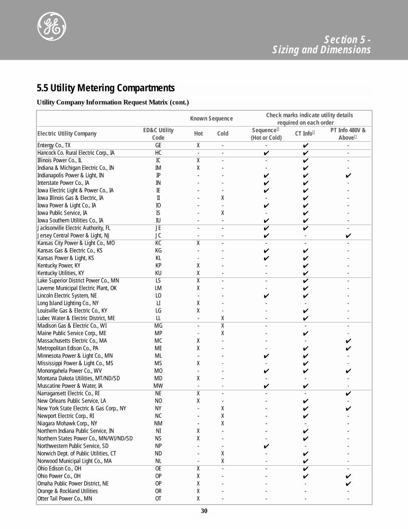
Utility Company Information Request Matrix (cont.)
Known Sequence Check marks indicate utility details required on each order
Electric Utility Company ED&C Utility Hot Cold Sequence①CT Info➁ PT Info 480V &
Code (Hot or Cold) Above➁
Entergy Co., TX GE X - - ✔ -Hancock Co. Rural Electric Corp., IA HC - - ✔ ✔ -Illinois Power Co., IL IC X - - ✔ -Indiana & Michigan Electric Co., IN IM X - - ✔ -Indianapolis Power & Light, IN IP - - ✔ ✔ ✔
Interstate Power Co., IA IN - - ✔ ✔ -Iowa Electric Light & Power Co., IA IE - - ✔ ✔ -Iowa Illinois Gas & Electric, IA II - X - ✔ -Iowa Power & Light Co., IA IO - - ✔ ✔ -Iowa Public Service, IA IS - X - ✔ -Iowa Southern Utilities Co., IA IU - - ✔ ✔ -Jacksonville Electric Authority, FL JE - - ✔ ✔ -Jersey Central Power & Light, NJ JC - - ✔ - ✔
Kansas City Power & Light Co., MO KC X - - - -Kansas Gas & Electric Co., KS KG - - ✔ ✔ -Kansas Power & Light, KS KL - - ✔ ✔ -Kentucky Power, KY KP X - - ✔ -Kentucky Utilities, KY KU X - - ✔ -Lake Superior District Power Co., MN LS X - - ✔ -Laverne Municipal Electric Plant, OK LM X - - ✔ -Lincoln Electric System, NE LO - - ✔ ✔ -Long Island Lighting Co., NY LI X - - - -Louisville Gas & Electric Co., KY LG X - - ✔ -Lubec Water & Electric District, ME LL - X - ✔ -Madison Gas & Electric Co., WI MG - X - - -Maine Public Service Corp., ME MP - X - ✔ -Massachusetts Electric Co., MA MC X - - - ✔
Metropolitan Edison Co., PA ME X - - ✔ ✔
Minnesota Power & Light Co., MN ML - - ✔ ✔ -Mississippi Power & Light Co., MS MS X - - ✔ -Monongahela Power Co., WV MO - - ✔ ✔ ✔
Montana Dakota Utilities, MT/ND/SD MD X - - - -Muscatine Power & Water, IA MW - - ✔ ✔ -Narragansett Electric Co., RI NE X - - - ✔
New Orleans Public Service, LA NO X - - ✔ -New York State Electric & Gas Corp., NY NY - X - ✔ ✔
Newport Electric Corp., RI NC - X - ✔ -Niagara Mohawk Corp., NY NM - X - - -Northern Indiana Public Service, IN NI X - - ✔ -Northern States Power Co., MN/WI/ND/SD NS X - - ✔ -Northwestern Public Service, SD NP - - ✔ - -Norwich Dept. of Public Utilities, CT ND - X - ✔ -Norwood Municipal Light Co., MA NL - X - ✔ -Ohio Edison Co., OH OE X - - ✔ -Ohio Power Co., OH OP X - - ✔ ✔
Omaha Public Power District, NE OP X - - - ✔
Orange & Rockland Utilities OR X - - - -Otter Tail Power Co., MN OT X - - - -
5.5 Utility Metering Compartments
31
Section 5 - Sizing and Dimensions
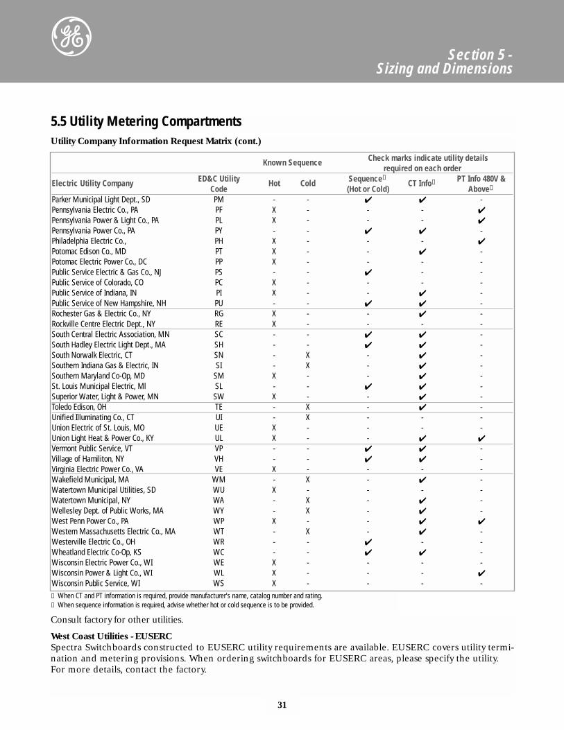
Utility Company Information Request Matrix (cont.)
Known Sequence Check marks indicate utility details required on each order
Electric Utility Company ED&C Utility Hot Cold Sequence①CT Info➁ PT Info 480V &
Code (Hot or Cold) Above➁
Parker Municipal Light Dept., SD PM - - ✔ ✔ -Pennsylvania Electric Co., PA PF X - - - ✔
Pennsylvania Power & Light Co., PA PL X - - - ✔
Pennsylvania Power Co., PA PY - - ✔ ✔ -Philadelphia Electric Co., PH X - - - ✔
Potomac Edison Co., MD PT X - - ✔ -Potomac Electric Power Co., DC PP X - - - -Public Service Electric & Gas Co., NJ PS - - ✔ - -Public Service of Colorado, CO PC X - - - -Public Service of Indiana, IN PI X - - ✔ -Public Service of New Hampshire, NH PU - - ✔ ✔ -Rochester Gas & Electric Co., NY RG X - - ✔ -Rockville Centre Electric Dept., NY RE X - - - -South Central Electric Association, MN SC - - ✔ ✔ -South Hadley Electric Light Dept., MA SH - - ✔ ✔ -South Norwalk Electric, CT SN - X - ✔ -Southern Indiana Gas & Electric, IN SI - X - ✔ -Southern Maryland Co-Op, MD SM X - - ✔ -St. Louis Municipal Electric, Ml SL - - ✔ ✔ -Superior Water, Light & Power, MN SW X - - ✔ -Toledo Edison, OH TE - X - ✔ -Unified Illuminating Co., CT UI - X - - -Union Electric of St. Louis, MO UE X - - - -Union Light Heat & Power Co., KY UL X - - ✔ ✔
Vermont Public Service, VT VP - - ✔ ✔ -Village of Hamiliton, NY VH - - ✔ ✔ -Virginia Electric Power Co., VA VE X - - - -Wakefield Municipal, MA WM - X - ✔ -Watertown Municipal Utilities, SD WU X - - - -Watertown Municipal, NY WA - X - ✔ -Wellesley Dept. of Public Works, MA WY - X - ✔ -West Penn Power Co., PA WP X - - ✔ ✔
Western Massachusetts Electric Co., MA WT - X - ✔ -Westerville Electric Co., OH WR - - ✔ - -Wheatland Electric Co-Op, KS WC - - ✔ ✔ -Wisconsin Electric Power Co., WI WE X - - - -Wisconsin Power & Light Co., WI WL X - - - ✔
Wisconsin Public Service, WI WS X - - - -
5.5 Utility Metering Compartments
① When CT and PT information is required, provide manufacturer's name, catalog number and rating.➁ When sequence information is required, advise whether hot or cold sequence is to be provided.
Consult factory for other utilities.
West Coast Utilities - EUSERCSpectra Switchboards constructed to EUSERC utility requirements are available. EUSERC covers utility termi-nation and metering provisions. When ordering switchboards for EUSERC areas, please specify the utility.For more details, contact the factory.
32
Section 5 - Sizing and Dimensions
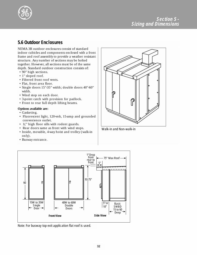
NEMA 3R outdoor enclosures consist of standardindoor cubicles and components enclosed with a frontframe and roof assembly to provide a weather resistantstructure. Any number of sections may be boltedtogether. However, all sections must be of the samedepth. Standard outdoor construction consists of:• 90" high sections. • 1" sloped roof.• Filtered front roof vents.• Flat, front area floor.• Single doors 15"-35" width; double doors 40"-60"
width.• Wind stop on each door.• 3-point catch with provision for padlock.• Front to rear full depth lifting beams.
Options available are:• Gasketing.• Fluorescent light, 120-volt, 15-amp and grounded
convenience outlet.• 1(" high floor sills with rodent guards.• Rear doors same as front with wind stops.• Inside, movable, 4-way hoist and trolley (walk-in
only).• Busway entrance.
5.6 Outdoor Enclosures
Walk-in and Non-walk-in
75” Max Roof
5”
5" or10”
BasicSWBD15 to 60Deep
40W to 60WDoubleDoors
15W to 35WSingleDoor
90
Side View
93.75”
Front View
1" Dropfrom
rear tofront
Note: For busway top exit application flat roof is used.
33
Section 5 - Sizing and Dimensions
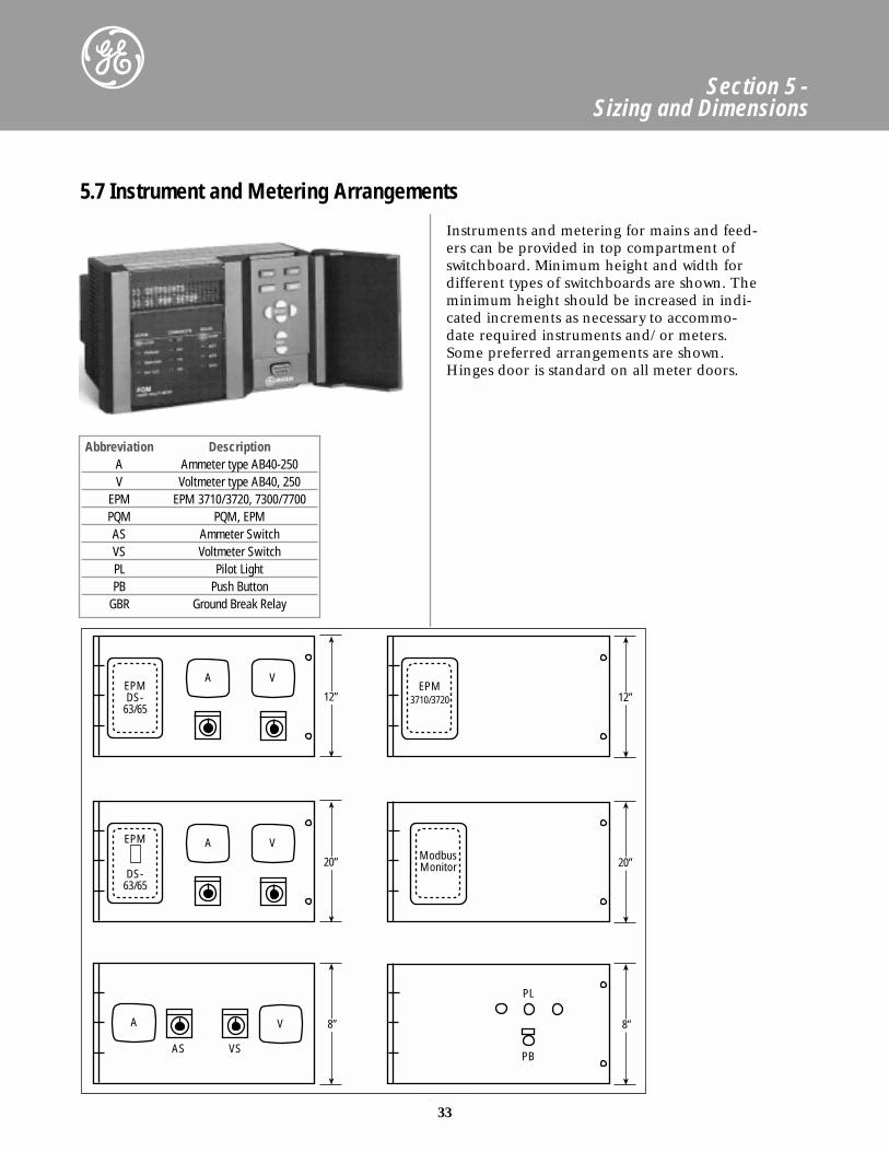
Abbreviation DescriptionA Ammeter type AB40-250V Voltmeter type AB40, 250
EPM EPM 3710/3720, 7300/7700PQM PQM, EPMAS Ammeter SwitchVS Voltmeter SwitchPL Pilot LightPB Push Button
GBR Ground Break Relay
5.7 Instrument and Metering Arrangements
Instruments and metering for mains and feed-ers can be provided in top compartment ofswitchboard. Minimum height and width fordifferent types of switchboards are shown. Theminimum height should be increased in indi-cated increments as necessary to accommo-date required instruments and/or meters.Some preferred arrangements are shown.Hinges door is standard on all meter doors.
12”EPMDS-
63/65
A V
20”
EPM
DS-63/65
A V
8”A V
AS VS
12”EPM
3710/3720
20”ModbusMonitor
8”
PB
PL
34
Section 5 - Sizing and Dimensions
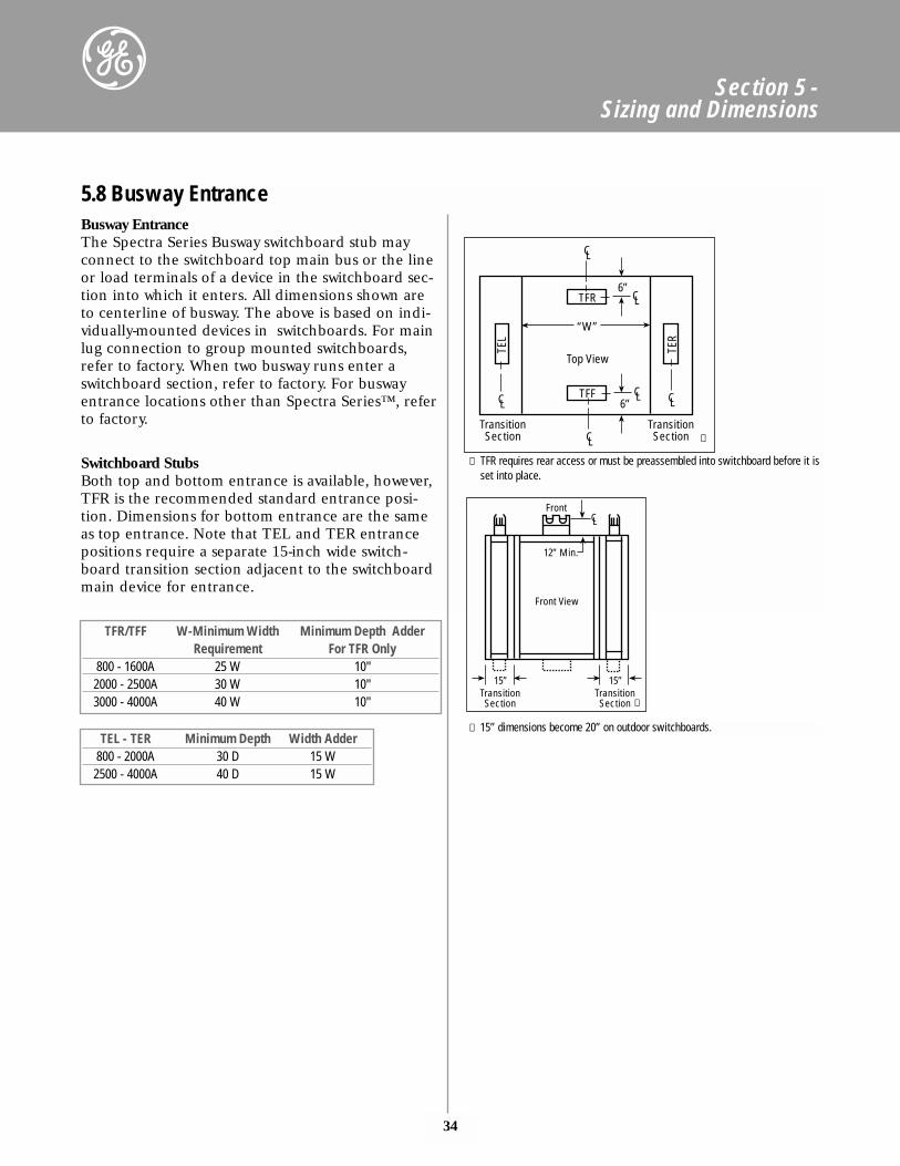
Switchboard StubsBoth top and bottom entrance is available, however,TFR is the recommended standard entrance posi-tion. Dimensions for bottom entrance are the sameas top entrance. Note that TEL and TER entrancepositions require a separate 15-inch wide switch-board transition section adjacent to the switchboardmain device for entrance.
Busway EntranceThe Spectra Series Busway switchboard stub mayconnect to the switchboard top main bus or the lineor load terminals of a device in the switchboard sec-tion into which it enters. All dimensions shown areto centerline of busway. The above is based on indi-vidually-mounted devices in switchboards. For mainlug connection to group mounted switchboards,refer to factory. When two busway runs enter aswitchboard section, refer to factory. For buswayentrance locations other than Spectra Series™, referto factory.
TFR/TFF W-Minimum Width Minimum Depth AdderRequirement For TFR Only
800 - 1600A 25 W 10"2000 - 2500A 30 W 10"3000 - 4000A 40 W 10"
TEL - TER Minimum Depth Width Adder800 - 2000A 30 D 15 W2500 - 4000A 40 D 15 W
5.8 Busway Entrance
TEL
TER
TFR
TFF
“W”
Top View
6”
6”
CLCL
CL
CL
CL
CL
TransitionSection
TransitionSection
Front
12” Min.
CL
Front View
15”TransitionSection
15”TransitionSection
➁ 15” dimensions become 20” on outdoor switchboards.
① TFR requires rear access or must be preassembled into switchboard before it isset into place.
①
➁
35
Section 5 - Sizing and Dimensions
KVA Self-CooledWidth Depth
30 30" 35"45 30" 35"75 35" 35"
112.5 40" 35"150 45" 40"225 45" 40"300 55" 45"500 55" 45"750 50" 60"1000 50" 60"
5.9 Low Voltage Transition Sections and Dual Voltage Switchboards
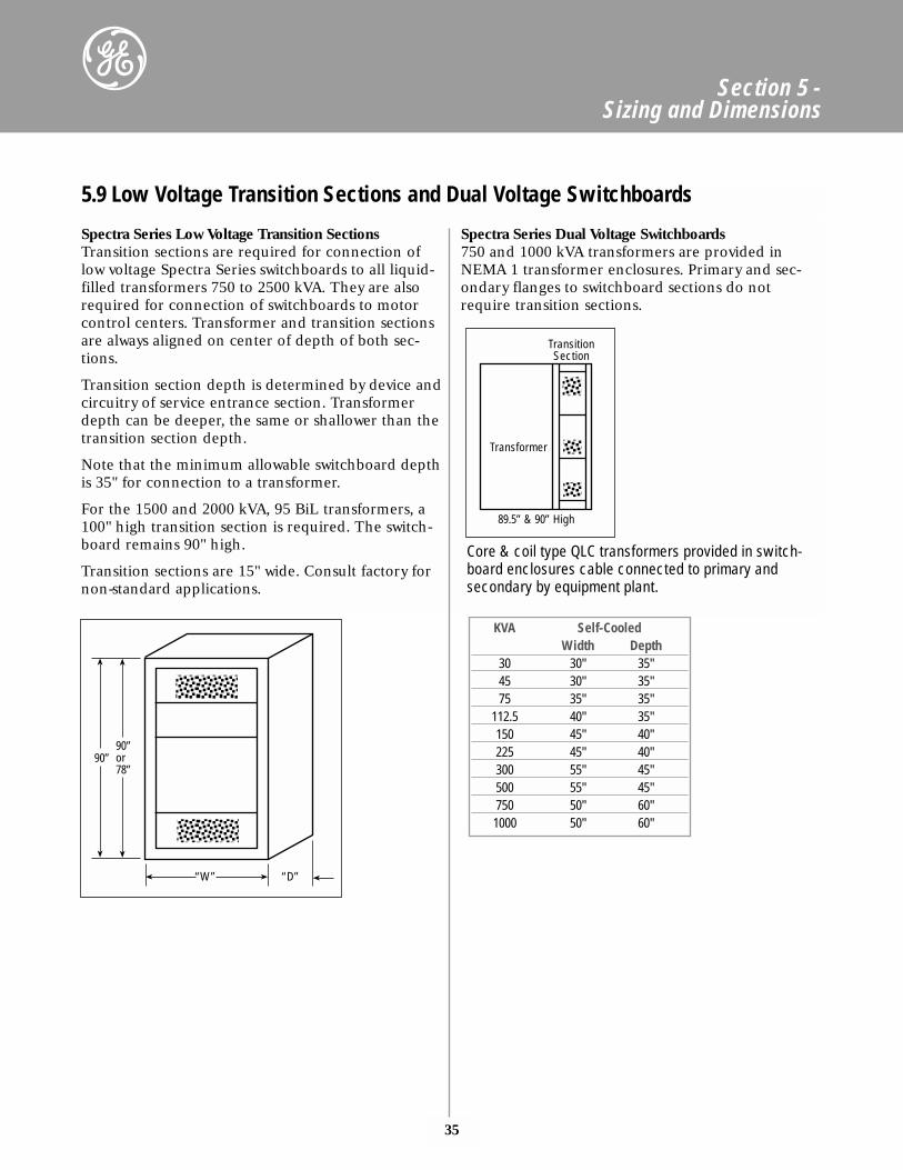
Spectra Series Low Voltage Transition SectionsTransition sections are required for connection oflow voltage Spectra Series switchboards to all liquid-filled transformers 750 to 2500 kVA. They are alsorequired for connection of switchboards to motorcontrol centers. Transformer and transition sectionsare always aligned on center of depth of both sec-tions.
Transition section depth is determined by device andcircuitry of service entrance section. Transformerdepth can be deeper, the same or shallower than thetransition section depth.
Note that the minimum allowable switchboard depthis 35" for connection to a transformer.
For the 1500 and 2000 kVA, 95 BiL transformers, a100" high transition section is required. The switch-board remains 90" high.
Transition sections are 15" wide. Consult factory fornon-standard applications.
Spectra Series Dual Voltage Switchboards750 and 1000 kVA transformers are provided inNEMA 1 transformer enclosures. Primary and sec-ondary flanges to switchboard sections do notrequire transition sections.
Transformer
89.5” & 90” High
TransitionSection
90”or78”
90”
“W” “D”
Core & coil type QLC transformers provided in switch-board enclosures cable connected to primary and secondary by equipment plant.
36
Section 5 - Sizing and Dimensions
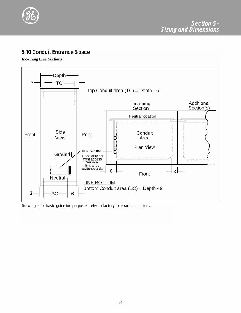
Incoming Line Sections
5.10 Conduit Entrance Space
SideView
Front
Front
Rear
Aux Neutral
Neutral location
IncomingSection
Top Conduit area (TC) = Depth - 6"
ConduitArea
Plan View
AdditionalSection(s)
Used only onfront access
Service Entrance
switchboards
Depth
TC3
6 3
LINE BOTTOMBottom Conduit area (BC) = Depth - 9"
BC 63
Ground
Neutral
Drawing is for basic guideline purposes, refer to factory for exact dimensions.
37
Section 5 - Sizing and Dimensions
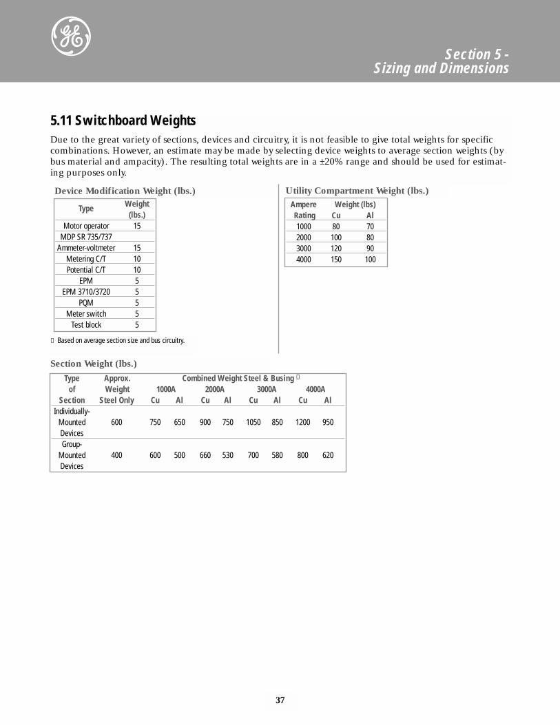
Due to the great variety of sections, devices and circuitry, it is not feasible to give total weights for specificcombinations. However, an estimate may be made by selecting device weights to average section weights (bybus material and ampacity). The resulting total weights are in a ±20% range and should be used for estimat-ing purposes only.
Ampere Weight (lbs)Rating Cu Al1000 80 702000 100 803000 120 904000 150 100
① Based on average section size and bus circuitry.
5.11 Switchboard Weights
Utility Compartment Weight (lbs.)
Type Weight (lbs.)
Motor operator 15MDP SR 735/737
Ammeter-voltmeter 15Metering C/T 10Potential C/T 10
EPM 5EPM 3710/3720 5
PQM 5Meter switch 5
Test block 5
Type Approx. Combined Weight Steel & Busing ①
of Weight 1000A 2000A 3000A 4000ASection Steel Only Cu Al Cu Al Cu Al Cu Al
Individually-Mounted 600 750 650 900 750 1050 850 1200 950DevicesGroup-
Mounted 400 600 500 660 530 700 580 800 620Devices
Device Modification Weight (lbs.)
Section Weight (lbs.)
38
Section 5 - Sizing and Dimensions
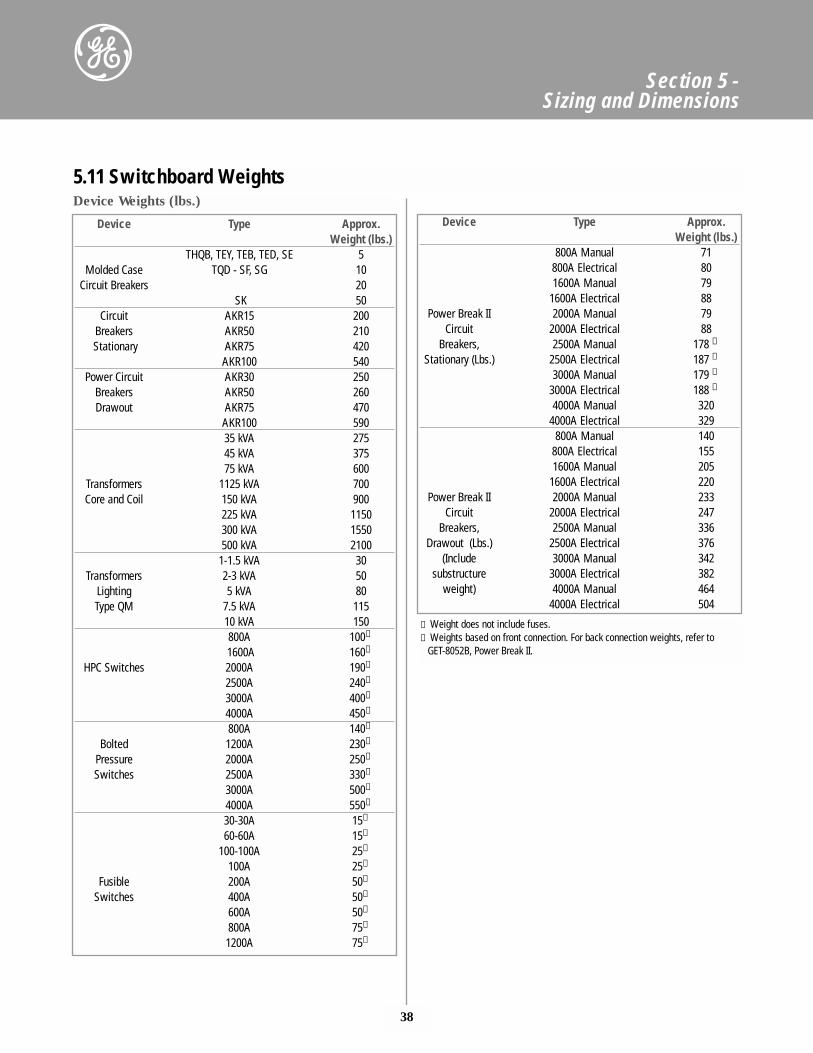
5.11 Switchboard WeightsDevice Weights (lbs.)
Device Type Approx. Weight (lbs.)
THQB, TEY, TEB, TED, SE 5Molded Case TQD - SF, SG 10
Circuit Breakers 20SK 50
Circuit AKR15 200Breakers AKR50 210Stationary AKR75 420
AKR100 540Power Circuit AKR30 250
Breakers AKR50 260Drawout AKR75 470
AKR100 59035 kVA 27545 kVA 37575 kVA 600
Transformers 1125 kVA 700Core and Coil 150 kVA 900
225 kVA 1150300 kVA 1550500 kVA 2100
1-1.5 kVA 30Transformers 2-3 kVA 50
Lighting 5 kVA 80Type QM 7.5 kVA 115
10 kVA 150800A 100①
1600A 160①
HPC Switches 2000A 190①
2500A 240①
3000A 400①
4000A 450①
800A 140①
Bolted 1200A 230①
Pressure 2000A 250①
Switches 2500A 330①
3000A 500①
4000A 550①
30-30A 15①
60-60A 15①
100-100A 25①
100A 25①
Fusible 200A 50①
Switches 400A 50①
600A 50①
800A 75①
1200A 75①
Device Type Approx. Weight (lbs.)
800A Manual 71800A Electrical 801600A Manual 79
1600A Electrical 88Power Break II 2000A Manual 79
Circuit 2000A Electrical 88Breakers, 2500A Manual 178 ➁
Stationary (Lbs.) 2500A Electrical 187 ➁
3000A Manual 179 ➁
3000A Electrical 188 ➁
4000A Manual 3204000A Electrical 329
800A Manual 140800A Electrical 1551600A Manual 205
1600A Electrical 220Power Break II 2000A Manual 233
Circuit 2000A Electrical 247Breakers, 2500A Manual 336
Drawout (Lbs.) 2500A Electrical 376(Include 3000A Manual 342
substructure 3000A Electrical 382weight) 4000A Manual 464
4000A Electrical 504
① Weight does not include fuses.➁ Weights based on front connection. For back connection weights, refer to
GET-8052B, Power Break II.
39
Section 6 - Application Data
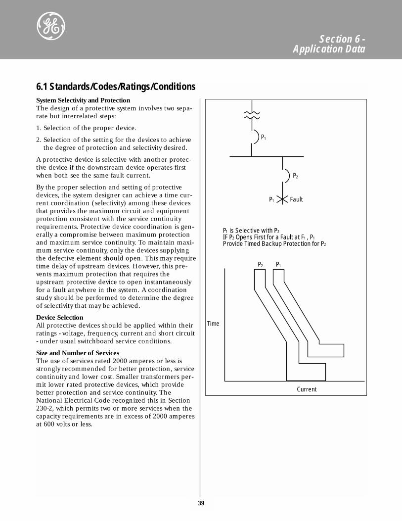
System Selectivity and ProtectionThe design of a protective system involves two sepa-rate but interrelated steps:
1. Selection of the proper device.
2. Selection of the setting for the devices to achievethe degree of protection and selectivity desired.
A protective device is selective with another protec-tive device if the downstream device operates firstwhen both see the same fault current.
By the proper selection and setting of protectivedevices, the system designer can achieve a time cur-rent coordination (selectivity) among these devicesthat provides the maximum circuit and equipmentprotection consistent with the service continuityrequirements. Protective device coordination is gen-erally a compromise between maximum protectionand maximum service continuity. To maintain maxi-mum service continuity, only the devices supplyingthe defective element should open. This may requiretime delay of upstream devices. However, this pre-vents maximum protection that requires theupstream protective device to open instantaneouslyfor a fault anywhere in the system. A coordinationstudy should be performed to determine the degreeof selectivity that may be achieved.
Device Selection All protective devices should be applied within theirratings - voltage, frequency, current and short circuit- under usual switchboard service conditions.
Size and Number of Services The use of services rated 2000 amperes or less isstrongly recommended for better protection, servicecontinuity and lower cost. Smaller transformers per-mit lower rated protective devices, which providebetter protection and service continuity. TheNational Electrical Code recognized this in Section230-2, which permits two or more services when thecapacity requirements are in excess of 2000 amperesat 600 volts or less.
6.1 Standards/Codes/Ratings/Conditions
Current
Time
P is Selective with PIF P Opens First for a Fault at F , PProvide Timed Backup Protection for P
1
2
2
2
1 1
P2
P2
1P
1P
1P
Fault
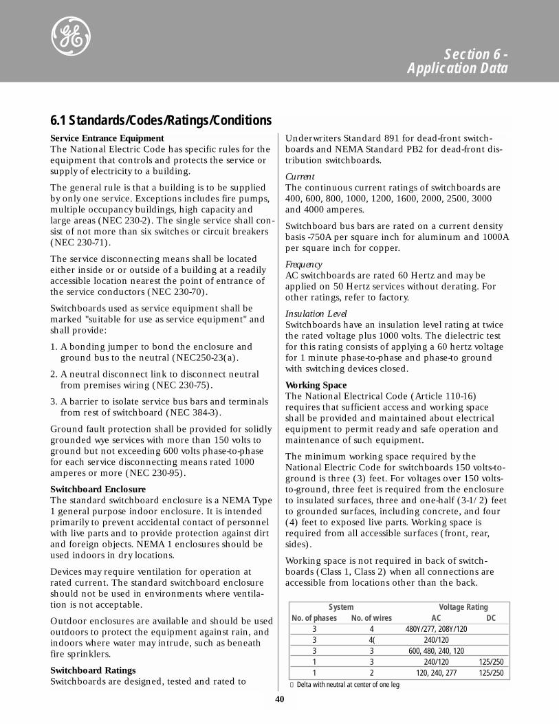
40
Section 6 - Application Data
Service Entrance EquipmentThe National Electric Code has specific rules for theequipment that controls and protects the service orsupply of electricity to a building.
The general rule is that a building is to be suppliedby only one service. Exceptions includes fire pumps,multiple occupancy buildings, high capacity andlarge areas (NEC 230-2). The single service shall con-sist of not more than six switches or circuit breakers(NEC 230-71).
The service disconnecting means shall be locatedeither inside or or outside of a building at a readilyaccessible location nearest the point of entrance ofthe service conductors (NEC 230-70).
Switchboards used as service equipment shall bemarked "suitable for use as service equipment" andshall provide:
1. A bonding jumper to bond the enclosure andground bus to the neutral (NEC250-23(a).
2. A neutral disconnect link to disconnect neutralfrom premises wiring (NEC 230-75).
3. A barrier to isolate service bus bars and terminalsfrom rest of switchboard (NEC 384-3).
Ground fault protection shall be provided for solidlygrounded wye services with more than 150 volts toground but not exceeding 600 volts phase-to-phasefor each service disconnecting means rated 1000amperes or more (NEC 230-95).
Switchboard EnclosureThe standard switchboard enclosure is a NEMA Type1 general purpose indoor enclosure. It is intendedprimarily to prevent accidental contact of personnelwith live parts and to provide protection against dirtand foreign objects. NEMA 1 enclosures should beused indoors in dry locations.
Devices may require ventilation for operation atrated current. The standard switchboard enclosureshould not be used in environments where ventila-tion is not acceptable.
Outdoor enclosures are available and should be usedoutdoors to protect the equipment against rain, andindoors where water may intrude, such as beneathfire sprinklers.
Switchboard RatingsSwitchboards are designed, tested and rated to
Underwriters Standard 891 for dead-front switch-boards and NEMA Standard PB2 for dead-front dis-tribution switchboards.
CurrentThe continuous current ratings of switchboards are400, 600, 800, 1000, 1200, 1600, 2000, 2500, 3000and 4000 amperes.
Switchboard bus bars are rated on a current densitybasis -750A per square inch for aluminum and 1000Aper square inch for copper.
FrequencyAC switchboards are rated 60 Hertz and may beapplied on 50 Hertz services without derating. Forother ratings, refer to factory.
Insulation LevelSwitchboards have an insulation level rating at twicethe rated voltage plus 1000 volts. The dielectric testfor this rating consists of applying a 60 hertz voltagefor 1 minute phase-to-phase and phase-to groundwith switching devices closed.
Working SpaceThe National Electrical Code (Article 110-16)requires that sufficient access and working spaceshall be provided and maintained about electricalequipment to permit ready and safe operation andmaintenance of such equipment.
The minimum working space required by theNational Electric Code for switchboards 150 volts-to-ground is three (3) feet. For voltages over 150 volts-to-ground, three feet is required from the enclosureto insulated surfaces, three and one-half (3-1/2) feetto grounded surfaces, including concrete, and four(4) feet to exposed live parts. Working space isrequired from all accessible surfaces (front, rear,sides).
Working space is not required in back of switch-boards (Class 1, Class 2) when all connections areaccessible from locations other than the back.
6.1 Standards/Codes/Ratings/Conditions
System Voltage RatingNo. of phases No. of wires AC DC
3 4 480Y/277, 208Y/1203 4( 240/1203 3 600, 480, 240, 1201 3 240/120 125/2501 2 120, 240, 277 125/250
① Delta with neutral at center of one leg
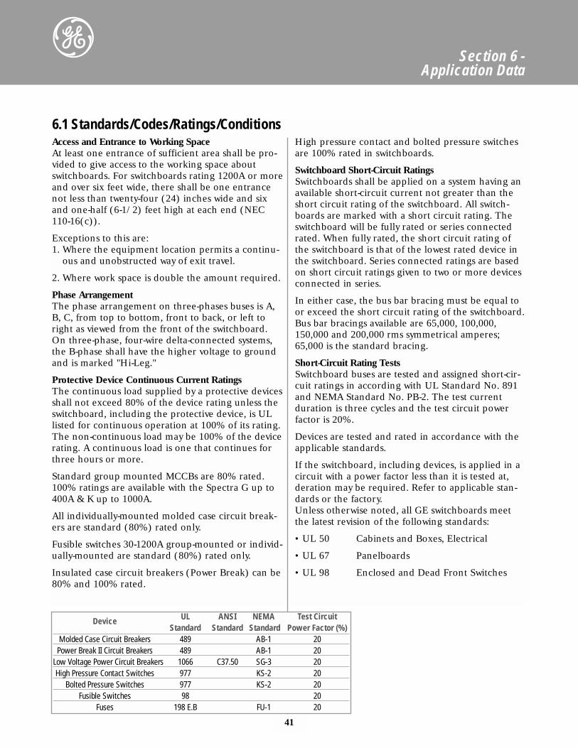
41
Section 6 - Application Data
Access and Entrance to Working SpaceAt least one entrance of sufficient area shall be pro-vided to give access to the working space aboutswitchboards. For switchboards rating 1200A or moreand over six feet wide, there shall be one entrancenot less than twenty-four (24) inches wide and sixand one-half (6-1/2) feet high at each end (NEC110-16(c)).
Exceptions to this are:1. Where the equipment location permits a continu-
ous and unobstructed way of exit travel.
2. Where work space is double the amount required.
Phase ArrangementThe phase arrangement on three-phases buses is A,B, C, from top to bottom, front to back, or left toright as viewed from the front of the switchboard.On three-phase, four-wire delta-connected systems,the B-phase shall have the higher voltage to groundand is marked "Hi-Leg."
Protective Device Continuous Current RatingsThe continuous load supplied by a protective devicesshall not exceed 80% of the device rating unless theswitchboard, including the protective device, is ULlisted for continuous operation at 100% of its rating.The non-continuous load may be 100% of the devicerating. A continuous load is one that continues forthree hours or more.
Standard group mounted MCCBs are 80% rated.100% ratings are available with the Spectra G up to400A & K up to 1000A.
All individually-mounted molded case circuit break-ers are standard (80%) rated only.
Fusible switches 30-1200A group-mounted or individ-ually-mounted are standard (80%) rated only.
Insulated case circuit breakers (Power Break) can be80% and 100% rated.
High pressure contact and bolted pressure switchesare 100% rated in switchboards.
Switchboard Short-Circuit RatingsSwitchboards shall be applied on a system having anavailable short-circuit current not greater than theshort circuit rating of the switchboard. All switch-boards are marked with a short circuit rating. Theswitchboard will be fully rated or series connectedrated. When fully rated, the short circuit rating ofthe switchboard is that of the lowest rated device inthe switchboard. Series connected ratings are basedon short circuit ratings given to two or more devicesconnected in series.
In either case, the bus bar bracing must be equal toor exceed the short circuit rating of the switchboard.Bus bar bracings available are 65,000, 100,000,150,000 and 200,000 rms symmetrical amperes;65,000 is the standard bracing.
Short-Circuit Rating TestsSwitchboard buses are tested and assigned short-cir-cuit ratings in according with UL Standard No. 891and NEMA Standard No. PB-2. The test currentduration is three cycles and the test circuit powerfactor is 20%.
Devices are tested and rated in accordance with theapplicable standards.
If the switchboard, including devices, is applied in acircuit with a power factor less than it is tested at,deration may be required. Refer to applicable stan-dards or the factory.Unless otherwise noted, all GE switchboards meetthe latest revision of the following standards:
• UL 50 Cabinets and Boxes, Electrical
• UL 67 Panelboards
• UL 98 Enclosed and Dead Front Switches
6.1 Standards/Codes/Ratings/Conditions
Device UL ANSI NEMA Test Circuit Standard Standard Standard Power Factor (%)
Molded Case Circuit Breakers 489 AB-1 20Power Break II Circuit Breakers 489 AB-1 20
Low Voltage Power Circuit Breakers 1066 C37.50 SG-3 20High Pressure Contact Switches 977 KS-2 20
Bolted Pressure Switches 977 KS-2 20Fusible Switches 98 20
Fuses 198 E.B FU-1 20
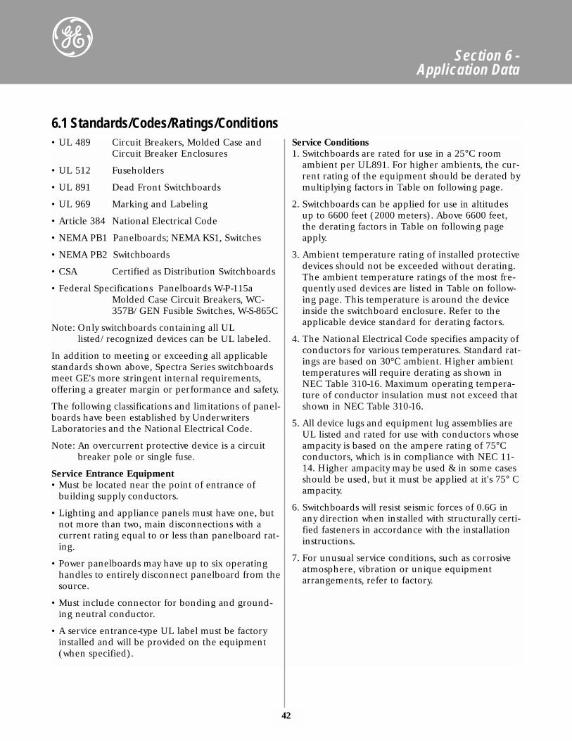
42
• UL 489 Circuit Breakers, Molded Case andCircuit Breaker Enclosures
• UL 512 Fuseholders
• UL 891 Dead Front Switchboards
• UL 969 Marking and Labeling
• Article 384 National Electrical Code
• NEMA PB1 Panelboards; NEMA KS1, Switches
• NEMA PB2 Switchboards
• CSA Certified as Distribution Switchboards
• Federal Specifications Panelboards W-P-115aMolded Case Circuit Breakers, WC-357B/GEN Fusible Switches, W-S-865C
Note: Only switchboards containing all ULlisted/recognized devices can be UL labeled.
In addition to meeting or exceeding all applicablestandards shown above, Spectra Series switchboardsmeet GE's more stringent internal requirements,offering a greater margin or performance and safety.
The following classifications and limitations of panel-boards have been established by UnderwritersLaboratories and the National Electrical Code.
Note: An overcurrent protective device is a circuitbreaker pole or single fuse.
Service Entrance Equipment• Must be located near the point of entrance of
building supply conductors.
• Lighting and appliance panels must have one, butnot more than two, main disconnections with acurrent rating equal to or less than panelboard rat-ing.
• Power panelboards may have up to six operatinghandles to entirely disconnect panelboard from thesource.
• Must include connector for bonding and ground-ing neutral conductor.
• A service entrance-type UL label must be factoryinstalled and will be provided on the equipment(when specified).
Service Conditions1. Switchboards are rated for use in a 25°C room
ambient per UL891. For higher ambients, the cur-rent rating of the equipment should be derated bymultiplying factors in Table on following page.
2. Switchboards can be applied for use in altitudesup to 6600 feet (2000 meters). Above 6600 feet,the derating factors in Table on following pageapply.
3. Ambient temperature rating of installed protectivedevices should not be exceeded without derating.The ambient temperature ratings of the most fre-quently used devices are listed in Table on follow-ing page. This temperature is around the deviceinside the switchboard enclosure. Refer to theapplicable device standard for derating factors.
4. The National Electrical Code specifies ampacity ofconductors for various temperatures. Standard rat-ings are based on 30°C ambient. Higher ambienttemperatures will require derating as shown inNEC Table 310-16. Maximum operating tempera-ture of conductor insulation must not exceed thatshown in NEC Table 310-16.
5. All device lugs and equipment lug assemblies areUL listed and rated for use with conductors whoseampacity is based on the ampere rating of 75°Cconductors, which is in compliance with NEC 11-14. Higher ampacity may be used & in some casesshould be used, but it must be applied at it's 75° Campacity.
6. Switchboards will resist seismic forces of 0.6G inany direction when installed with structurally certi-fied fasteners in accordance with the installationinstructions.
7. For unusual service conditions, such as corrosiveatmosphere, vibration or unique equipmentarrangements, refer to factory.
Section 6 - Application Data
6.1 Standards/Codes/Ratings/Conditions
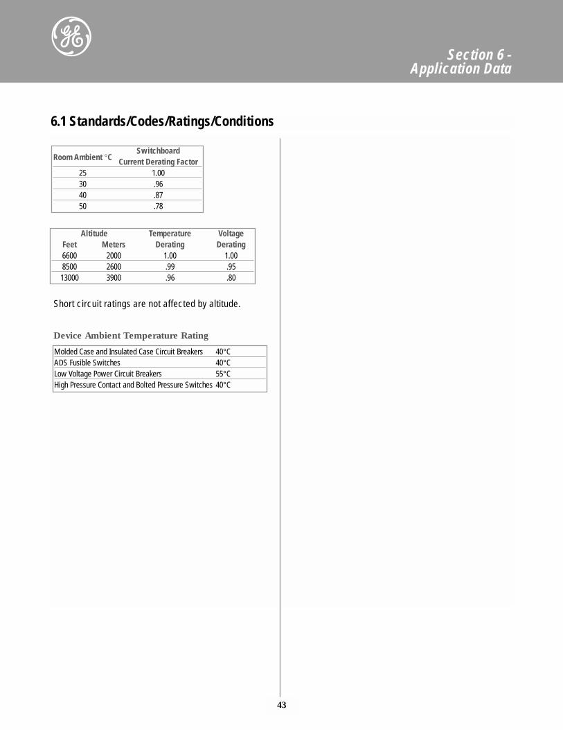
43
Section 6 - Application Data
Room Ambient °CSwitchboard
Current Derating Factor25 1.0030 .9640 .8750 .78
Altitude Temperature VoltageFeet Meters Derating Derating6600 2000 1.00 1.008500 2600 .99 .9513000 3900 .96 .80
Molded Case and Insulated Case Circuit Breakers 40°CADS Fusible Switches 40°CLow Voltage Power Circuit Breakers 55°CHigh Pressure Contact and Bolted Pressure Switches 40°C
6.1 Standards/Codes/Ratings/Conditions
Device Ambient Temperature Rating
Short circuit ratings are not affected by altitude.
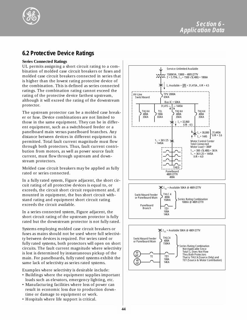
44
Section 6 - Application Data
Series Connected RatingsUL permits assigning a short circuit rating to a com-bination of molded case circuit breakers or fuses andmolded case circuit breakers connected in series thatis higher than the lowest rating protective device ofthe combination. This is defined as series connectedratings. The combination rating cannot exceed therating of the protective device farthest upstream,although it will exceed the rating of the downstreamprotector.
The upstream protector can be a molded case break-er or fuse. Device combinations are not limited tothose in the same equipment. They can be in differ-ent equipment, such as a switchboard feeder or apanelboard main versus panelboard branches. Anydistance between devices in different equipment ispermitted. Total fault current magnitude must flowthrough both protectors. Thus, fault current contri-bution from motors, as well as power source faultcurrent, must flow through upstream and down-stream protectors.
Molded case circuit breakers may be applied as fullyrated or series connected.
In a fully rated system, Figure adjacent, the short cir-cuit rating of all protective devices is equal to, orexceeds, the circuit short circuit requirement and, ifmounted in equipment, the bus short circuit with-stand rating and equipment short circuit ratingexceeds the circuit available.
In a series connected system, Figure adjacent, theshort circuit rating of the upstream protector is fullyrated but the downstream protector is not fully rated.
Systems employing molded case circuit breakers orfuses as mains should not be used where full selectivi-ty between devices is required. For series rated orfully rated systems, both protectors will open on shortcircuits. The fault current magnitude where selectivityis lost is determined by instantaneous pickup of themain. For panelboards, fully rated systems exhibit thesame lack of selectivity as series rated systems.
Examples where selectivity is desirable include:• Buildings where the equipment supplies important
loads such as elevators, emergency lighting, etc.• Manufacturing facilities where loss of power can
result in economic loss due to production down-time or damage to equipment or work.
• Hospitals where life support is critical.
6.2 Protective Device Ratings
I Available = = 31,415A., X/R = 4.5 SC1806.0575
AV-Line Switchboard
TPV 2000A65KA
Bus IC = 50KA
THEDPanelboard480Y/277V
400A
THJK4400A35KA
TEL100A65KA
THJK4400A35KA
THJK4400A35KA
I = 30,000 SC
I = 1445 SC
I = 32,860 SC
X/R - 4.5
31,445AX/R = 3.6
31,415 1445A
Motor Control CenterTotol ConnectedMotor Load = 300P
1 = 361/.25= 1445A
SC
1 = 361/.25 = 1445A X/R = 4.0 SC
1 = 300 √3(.480) = 361A FLA
Service-Unlimited Available
1500KVA, 13800 – 480Y/277VZ = 5.75%, I = 1500 √3(.480) = 1806A FLA
Switchboard Feederor Panelboard Main
PanelboardBranch
THLC 4400A
150KA Series Rating Combination100KA @ 480Y/277V
I = Available 50KA @ 480Y/277V SC
TEY100A14KA
Figure 42.2
Series Rating Combination Not Applicable Since Total I Does Not Flow Thru Both Protectors That is THLC4 (Source Only) and TEY (Source & Motor Contribution)
SC
Switchboard Feederor Panelboard Main
50HP
40HP
TE
THLC4400A
150KA
I = Available 50KA @ 480Y/277V SC
TEY100A14KA
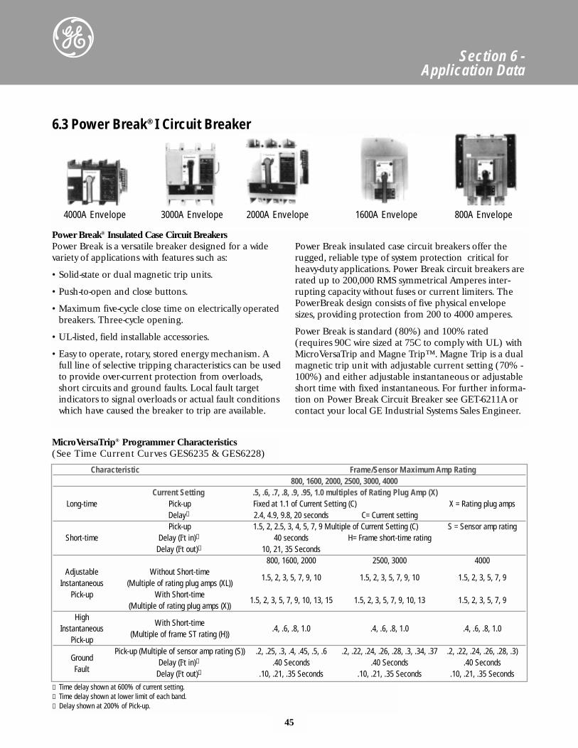
45
Section 6 - Application Data
Characteristic Frame/Sensor Maximum Amp Rating800, 1600, 2000, 2500, 3000, 4000
Current Setting .5, .6, .7, .8, .9, .95, 1.0 multiples of Rating Plug Amp (X)Long-time Pick-up Fixed at 1.1 of Current Setting (C) X = Rating plug amps
Delay➀ 2.4, 4.9, 9.8, 20 seconds C= Current settingPick-up 1.5, 2, 2.5, 3, 4, 5, 7, 9 Multiple of Current Setting (C) S = Sensor amp rating
Short-time Delay (I2t in)➀ 40 seconds H= Frame short-time ratingDelay (I2t out)➁ 10, 21, 35 Seconds
800, 1600, 2000 2500, 3000 4000Adjustable Without Short-time
Instantaneous (Multiple of rating plug amps (XL))1.5, 2, 3, 5, 7, 9, 10 1.5, 2, 3, 5, 7, 9, 10 1.5, 2, 3, 5, 7, 9
Pick-up With Short-time (Multiple of rating plug amps (X))
1.5, 2, 3, 5, 7, 9, 10, 13, 15 1.5, 2, 3, 5, 7, 9, 10, 13 1.5, 2, 3, 5, 7, 9
High Instantaneous
With Short-time .4, .6, .8, 1.0 .4, .6, .8, 1.0 .4, .6, .8, 1.0
Pick-up(Multiple of frame ST rating (H))
Pick-up (Multiple of sensor amp rating (S)) .2, .25, .3, .4, .45, .5, .6 .2, .22, .24, .26, .28, .3, .34, .37 .2, .22, .24, .26, .28, .3)Ground Delay (I2t in)➂ .40 Seconds .40 Seconds .40 SecondsFault Delay (I2t out)➁ .10, .21, .35 Seconds .10, .21, .35 Seconds .10, .21, .35 Seconds
6.3 Power Break® I Circuit Breaker
Power Break® Insulated Case Circuit BreakersPower Break is a versatile breaker designed for a widevariety of applications with features such as:
• Solid-state or dual magnetic trip units.
• Push-to-open and close buttons.
• Maximum five-cycle close time on electrically operatedbreakers. Three-cycle opening.
• UL-listed, field installable accessories.
• Easy to operate, rotary, stored energy mechanism. Afull line of selective tripping characteristics can be usedto provide over-current protection from overloads,short circuits and ground faults. Local fault target indicators to signal overloads or actual fault conditionswhich have caused the breaker to trip are available.
Power Break insulated case circuit breakers offer therugged, reliable type of system protection critical forheavy-duty applications. Power Break circuit breakers arerated up to 200,000 RMS symmetrical Amperes inter-rupting capacity without fuses or current limiters. ThePowerBreak design consists of five physical envelopesizes, providing protection from 200 to 4000 amperes.
Power Break is standard (80%) and 100% rated(requires 90C wire sized at 75C to comply with UL) withMicroVersaTrip and Magne Trip™. Magne Trip is a dualmagnetic trip unit with adjustable current setting (70% -100%) and either adjustable instantaneous or adjustableshort time with fixed instantaneous. For further informa-tion on Power Break Circuit Breaker see GET-6211A orcontact your local GE Industrial Systems Sales Engineer.
4000A Envelope 3000A Envelope 2000A Envelope 1600A Envelope 800A Envelope
MicroVersaTrip® Programmer Characteristics(See Time Current Curves GES6235 & GES6228)
① Time delay shown at 600% of current setting.➁ Time delay shown at lower limit of each band.➂ Delay shown at 200% of Pick-up.
MicroVersaTrip® Plus Trip UnitThe MicroVersaTrip Plus trip units utilize a digital,LCD display with a four-button keypad to providelocal set-up and read-out of trip settings. A 3-phaseammeter and trip indicators are standard, as is aclear plastic cover with provisions for sealing to allowtamper-resistant installation. The trip unit digitallymeasures the current waveform in each phase todetermine the true RMS value of the current, regard-less of the waveshape. MicroVersaTrip Plus trip unitsprovide accurate, predictable overload and short cir-cuit protection for standard circuits as well as distri-bution systems that include variable speed drives,rectifiers, induction heating and other loads that
cause high harmonic distortion. They provide opti-mum breaker-to-breaker selectivity and custom loadprotection. Shor-time and ground fault functionsinclude the flexibility of coordination with or with-out an I2t ramp and are also available with highrange instantaneous.
MicroVersaTrip PM Trip UnitThe MicroVersaTrip PM trip unit adds power man-agement system capability, including advancedmetering, and protective relays to the basic functionsof the MicroVersaTrip Plus. MicroVersaTrip PM tripunits communicate directly on the GE POWERLEADER™ communications bus (commnet).
46
Section 6 - Application Data
Programmer Long Short Instantaneous High GroundOL/SC OL/SC/GF GF Zone GF/ST Zone
Suffix -time (L) -time (S) (I) Inst. (H) Fault (G)Targets Targets Interlock Interlock
(T1) (T2) (Z2)Adjustable Instantaneous
L1 • •L1TI • • •LIG • • •
LIGT2 • • • •LIG2Z1 • • • •
LSI • • • •LSIT1 • • • •LSIG • • • •
LSIGT2 • • • • •LSIGT2Z1 • • • • • •LSIGT2Z2 • • • • • •
Adjustable High Range InstantaneousLSHT1 • • • •
LSHGT2 • • • • •LSHGT2Z1 • • • • • •LSHGT2Z2 • • • • • •
6.3 Power Break® I Circuit Breaker
MicroVersaTrip® Power Break Programmers
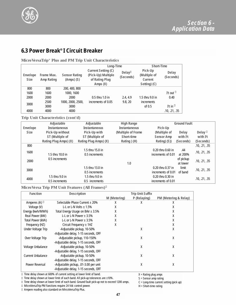
Section 6 - Application Data
6.3 Power Break® I Circuit Breaker
Adjustable Adjustable High Range Ground FaultEnvelope Instantaneous Instantaneous Instantaneous Pick-Up
Size Pick-Up without Pick-Up with (Multiple of Frame (Multiple of Delay Delay ➂ST (Multiple of ST (Multiple of Short-time Sensor Amp with I2t with I2t
Rating Plug Amps) (X) Rating Plug Amps) (X) Rating ) (H) Rating) (S)) (Seconds) (Seconds)800 .10, .21, .35
1.5 thru 15.0 in 0.20 thru 0.60 in .441600
1.5 thru 10.0 in 0.5 increments increments of 0.01 at 200%.10, .21, .35
0.5 increments of pickup2000
1.0 at lower .10, .21, .35
30001.5 thru 13.0 in 0.20 thru 0.37 in limit 0.5 increments increments of 0.01 of band
.10, .21, .35
40001.5 thru 9.0 in 1.5 thru 9.0 in 0.20 thru 0.30 in 0.5 increments 0.5 increments increments of 0.01
.10, .21, .35
Function Description Trip Unit SuffixM (Metering) P (Relaying) PM (Metering & Relay)
Amperes (A) ➄ Selectable Phase Current ± 20% X X XVoltage (V) L-L or L-N Volts ± 1.5% X X
Energy (kwh/MWh) Total Energy Usage on Brkr ± 3.5% X XReal Power (kW) L-L or L-N Power ± 3.5% X XTotal Power (kVA) L-L or L-N Power ± 3.5% X X
Frequency (HZ) Circuit Frequency ± 1HZ X XUnder Voltage Trip -Adjustable pickup, 10-50% X X
-Adjustable delay, 1-15 seconds, OFFOver Voltage Trip -Adjustable pickup, 110-150% X X
-Adjustable delay, 1-15 seconds, OFFVoltage Unbalance -Adjustable pickup, 10-50% X X
-Adjustable delay, 1-15 seconds, OFFCurrent Unbalance -Adjustable pickup, 10-50% X X
-Adjustable delay, 1-15 seconds, OFFPower Reversal -Adjustable pickup, .01-3.00 per unit X X
-Adjustable delay, 1-15 seconds, OFF
MicroVersaTrip® Plus and PM Trip Unit Characteristics
Trip Unit Characteristics (cont'd)
MicroVersa Trip PM Unit Features (All Frames)➃
Long-Time Short-TimeCurrent Setting (C) Delay① Pick-Up Delay
Envelope Frame Max. Sensor Rating (Pick-Up) Multiple (Seconds) (Multiple of (Seconds)Size Amp Rating (Amps) (S) of Rating Plug Current
Amps (X) Setting) (C)800 800 200, 400, 8001600 1600 1000, 1600 I2t out ①
2000 2000 2000 0.5 thru 1.0 in 2.4, 4.9 1.5 thru 9.0 in 0.40
30002500 1000, 2000, 2500, increments of 0.05 9.8, 20 increments3000 3000 of 0.5 I2t in ➁
4000 4000 4000 .10, .21, .35
① Time delay shown at 600% of current setting at lower limit of band.➁ Time delay shown at lower limit of each band. All pick-up tolerances are ±10%.➂ Time delay shown at lower limit of each band. Ground fault pick-up not to exceed 1200 amps.➃ MicroVersaTrip PM functions require 24 Vdc control power.➄ Ampere reading also standard on MircoVersaTrip Plus.
X = Rating plug ampsS = Sensor amp ratingC = Long-time current setting (pick up)H = Short-time rating
47
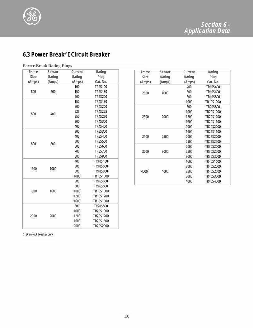
48
Section 6 - Application Data
Frame Sensor Current RatingSize Rating Rating Plug
(Amps) (Amps) (Amps) Cat. No.100 TR2S100
800 200 150 TR2S150200 TR2S200150 TR4S150200 TR4S200
800 400225 TR4S225250 TR4S250300 TR4S300400 TR4S400300 TR8S300400 TR8S400
800 800500 TR8S500600 TR8S600700 TR8S700800 TR8S800400 TR10S400
1600 1000600 TR10S600800 TR10S8001000 TR10S1000600 TR16S600800 TR16S800
1600 1600 1000 TR16S10001200 TR16S12001600 TR16S1600800 TR20S8001000 TR20S1000
2000 2000 1200 TR20S12001600 TR20S16002000 TR20S2000
Frame Sensor Current RatingSize Rating Rating Plug
(Amps) (Amps) (Amps) Cat. No.400 TR10S400
2500 1000 600 TR10S600800 TR10S8001000 TR10S1000800 TR20S8001000 TR20S1000
2500 2000 1200 TR20S12001600 TR20S16002000 TR20S20001600 TR25S1600
2500 2500 2000 TR25S20002500 TR25S25002000 TR30S2000
3000 3000 2500 TR30S25003000 TR30S30001600 TR40S16002000 TR40S2000
4000① 4000 2500 TR40S25003000 TR40S30004000 TR40S4000
① Draw-out breaker only.
6.3 Power Break® I Circuit Breaker
Power Break Rating Plugs
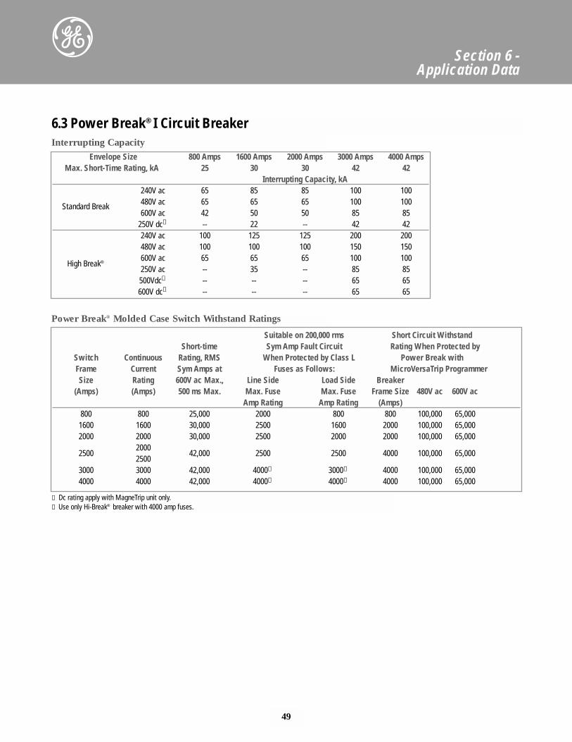
49
Section 6 - Application Data
6.3 Power Break® I Circuit Breaker
Envelope Size 800 Amps 1600 Amps 2000 Amps 3000 Amps 4000 AmpsMax. Short-Time Rating, kA 25 30 30 42 42
Interrupting Capacity, kA240V ac 65 85 85 100 100
Standard Break 480V ac 65 65 65 100 100600V ac 42 50 50 85 85
250V dc① -- 22 -- 42 42240V ac 100 125 125 200 200480V ac 100 100 100 150 150
High Break®600V ac 65 65 65 100 100250V ac -- 35 -- 85 85500Vdc① -- -- -- 65 65600V dc① -- -- -- 65 65
Suitable on 200,000 rms Short Circuit WithstandShort-time Sym Amp Fault Circuit Rating When Protected by
Switch Continuous Rating, RMS When Protected by Class L Power Break withFrame Current Sym Amps at Fuses as Follows: MicroVersaTrip ProgrammerSize Rating 600V ac Max., Line Side Load Side Breaker
(Amps) (Amps) 500 ms Max. Max. Fuse Max. Fuse Frame Size 480V ac 600V acAmp Rating Amp Rating (Amps)
800 800 25,000 2000 800 800 100,000 65,0001600 1600 30,000 2500 1600 2000 100,000 65,0002000 2000 30,000 2500 2000 2000 100,000 65,000
25002000
42,000 2500 2500 4000 100,000 65,0002500
3000 3000 42,000 4000➁ 3000➁ 4000 100,000 65,0004000 4000 42,000 4000➁ 4000➁ 4000 100,000 65,000
Interrupting Capacity
Power Break® Molded Case Switch Withstand Ratings
① Dc rating apply with MagneTrip unit only.➁ Use only Hi-Break® breaker with 4000 amp fuses.
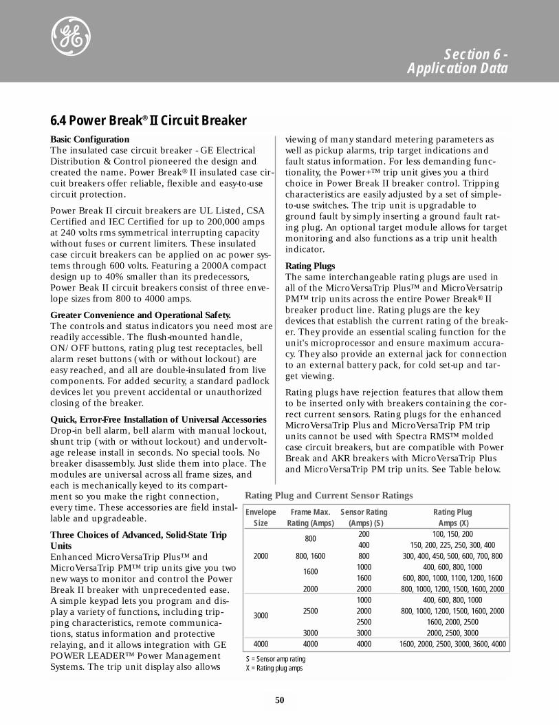
50
Section 6 - Application Data
Basic ConfigurationThe insulated case circuit breaker - GE ElectricalDistribution & Control pioneered the design andcreated the name. Power Break® II insulated case cir-cuit breakers offer reliable, flexible and easy-to-usecircuit protection.
Power Break II circuit breakers are UL Listed, CSACertified and IEC Certified for up to 200,000 ampsat 240 volts rms symmetrical interrupting capacitywithout fuses or current limiters. These insulatedcase circuit breakers can be applied on ac power sys-tems through 600 volts. Featuring a 2000A compactdesign up to 40% smaller than its predecessors,Power Beak II circuit breakers consist of three enve-lope sizes from 800 to 4000 amps.
Greater Convenience and Operational Safety.The controls and status indicators you need most arereadily accessible. The flush-mounted handle,ON/OFF buttons, rating plug test receptacles, bellalarm reset buttons (with or without lockout) areeasy reached, and all are double-insulated from livecomponents. For added security, a standard padlockdevices let you prevent accidental or unauthorizedclosing of the breaker.
Quick, Error-Free Installation of Universal AccessoriesDrop-in bell alarm, bell alarm with manual lockout,shunt trip (with or without lockout) and undervolt-age release install in seconds. No special tools. Nobreaker disassembly. Just slide them into place. Themodules are universal across all frame sizes, andeach is mechanically keyed to its compart-ment so you make the right connection,every time. These accessories are field instal-lable and upgradeable.
Three Choices of Advanced, Solid-State TripUnitsEnhanced MicroVersaTrip Plus™ andMicroVersaTrip PM™ trip units give you twonew ways to monitor and control the PowerBreak II breaker with unprecedented ease.A simple keypad lets you program and dis-play a variety of functions, including trip-ping characteristics, remote communica-tions, status information and protectiverelaying, and it allows integration with GEPOWER LEADER™ Power ManagementSystems. The trip unit display also allows
viewing of many standard metering parameters aswell as pickup alarms, trip target indications andfault status information. For less demanding func-tionality, the Power+™ trip unit gives you a thirdchoice in Power Break II breaker control. Trippingcharacteristics are easily adjusted by a set of simple-to-use switches. The trip unit is upgradable toground fault by simply inserting a ground fault rat-ing plug. An optional target module allows for targetmonitoring and also functions as a trip unit healthindicator.
Rating PlugsThe same interchangeable rating plugs are used inall of the MicroVersaTrip Plus™ and MicroVersatripPM™ trip units across the entire Power Break® IIbreaker product line. Rating plugs are the keydevices that establish the current rating of the break-er. They provide an essential scaling function for theunit's microprocessor and ensure maximum accura-cy. They also provide an external jack for connectionto an external battery pack, for cold set-up and tar-get viewing.
Rating plugs have rejection features that allow themto be inserted only with breakers containing the cor-rect current sensors. Rating plugs for the enhancedMicroVersaTrip Plus and MicroVersaTrip PM tripunits cannot be used with Spectra RMS™ moldedcase circuit breakers, but are compatible with PowerBreak and AKR breakers with MicroVersaTrip Plusand MicroVersaTrip PM trip units. See Table below.
6.4 Power Break® II Circuit Breaker
Envelope Frame Max. Sensor Rating Rating PlugSize Rating (Amps) (Amps) (S) Amps (X)
800 200 100, 150, 200400 150, 200, 225, 250, 300, 400
2000 800, 1600 800 300, 400, 450, 500, 600, 700, 800
1600 1000 400, 600, 800, 10001600 600, 800, 1000, 1100, 1200, 1600
2000 2000 800, 1000, 1200, 1500, 1600, 20001000 400, 600, 800, 1000
3000 2500 2000 800, 1000, 1200, 1500, 1600, 20002500 1600, 2000, 2500
3000 3000 2000, 2500, 30004000 4000 4000 1600, 2000, 2500, 3000, 3600, 4000
S = Sensor amp ratingX = Rating plug amps
Rating Plug and Current Sensor Ratings
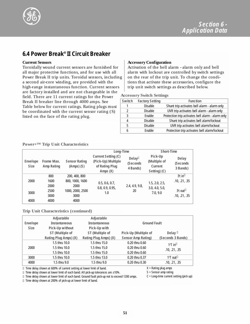
51
Section 6 - Application Data
Current SensorsToroidally wound current sensors are furnished forall major protective functions, and for use with allPower Break II trip units. Toroidal sensors, includinga second air-core winding, are provided with thehigh-range instantaneous function. Current sensorsare factory installed and are not changeable in thefield. There are 11 current ratings for the PowerBreak II breaker line through 4000 amps. SeeTable below for current ratings. Rating plugs mustbe coordinated with the current sensor rating (S)listed on the face of the rating plug.
Accessory ConfigurationActivation of the bell alarm - alarm only and bellalarm with lockout are controlled by switch settingson the rear of the trip unit. To change the condi-tions that activate these accessories, configure thetrip unit switch settings as described below.
Long-Time Short-TimeCurrent Setting (C) Delay① Pick-Up Delay
Envelope Frame Max. Sensor Rating (Pick-Up) Multiple (Seconds (Multiple of (SecondsSize Amp Rating (Amps) (S) of Rating Plug 4 Bands) Current 3 Bands)
Amps (X) Setting) (C)800 200, 400, 800 I2t in①
2000 1600 800, 1000, 1600 0.5, 0.6, 0.7, 1.5, 2.0, 2.5, .10, .21, .352000 2000 0.8, 0.9, 0.95, 2.4, 4.9, 9.8, 3.0, 4.0, 5.0,
3000 2500 1000, 2000, 2500 1.0 20 7.0, 9.0 I2t out➁
3000 3000 .10, .21, .354000 4000 4000
Adjustable Adjustable Envelope Instantaneous Instantaneous Ground Fault
Size Pick-Up without Pick-Up withST (Multiple of ST (Multiple of Pick-Up (Multiple of Delay ➂
Rating Plug Amps) (X) Rating Plug Amps) (X) Sensor Amp Rating) (Seconds 3 Bands)1.5 thru 10.0 1.5 thru 15.0 0.20 thru 0.60 12T in➃
2000 1.5 thru 10.0 1.5 thru 15.0 0.20 thru 0.60 .10, .21, .351.5 thru 10.0 1.5 thru 15.0 0.20 thru 0.60
3000 1.5 thru 10.0 1.5 thru 13.0 0.20 thru 0.37 12T out➁
4000 1.5 thru 9.0 1.5 thru 9.0 0.20 thru 0.30 .10, .21, .35
Switch Factory Setting Function1 Disable Shunt trip activates bell alarm - alarm only2 Disable UVR trip activates bell alarm - alarm only3 Enable Protection trip activates bell alarm - alarm only4 Disable Shunt trip activates bell alarm/lockout5 Disable UVR trip activates bell alarm/lockout6 Enable Protection trip activates bell alarm/lockout
6.4 Power Break® II Circuit Breaker
Accessory Switch Settings
Power+™ Trip Unit Characteristics
Trip Unit Characteristics (continued)
① Time delay shown at 600% of current setting at lower limit of band.➁ Time delay shown at lower limit of each band. All pick-up tolerances are ±10%.➂ Time delay shown at lower limit of each band. Ground fault pick-up not to exceed 1200 amps.➃ Time delay shown at 200% of pick-up at lower limit of band.
X = Rating plug ampsS = Sensor amp ratingC = Long-time current setting (pick up)
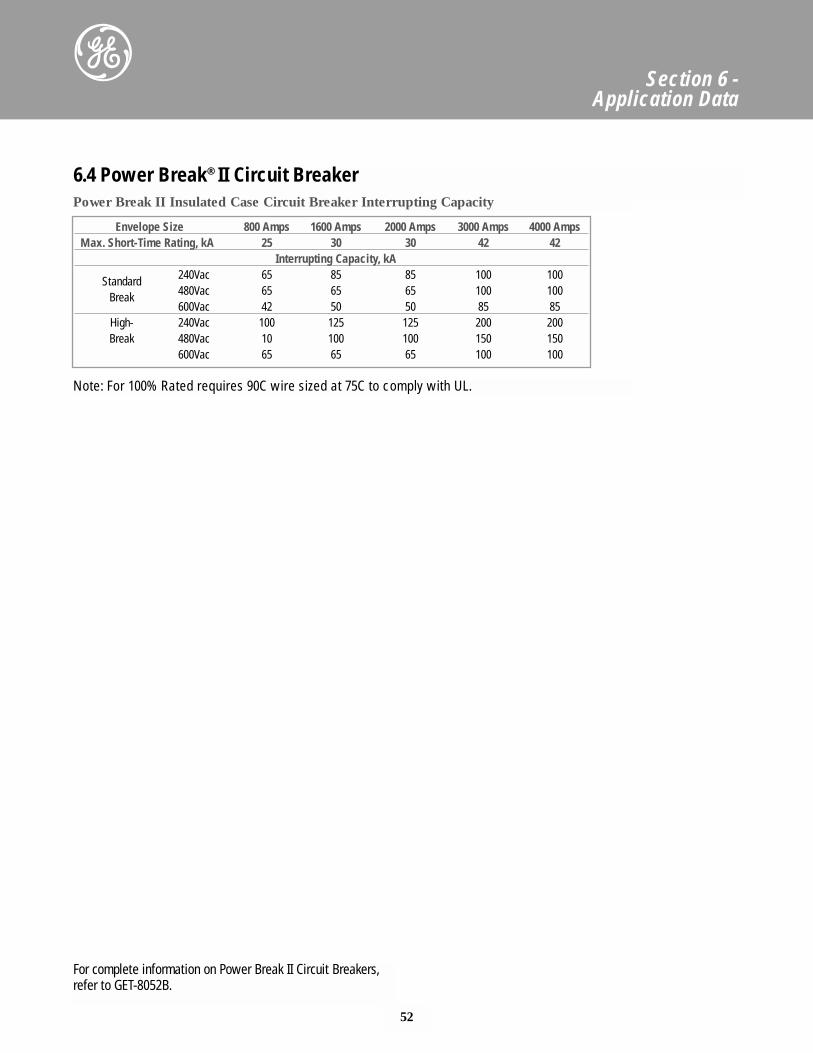
52
Section 6 - Application Data
6.4 Power Break® II Circuit Breaker
For complete information on Power Break II Circuit Breakers,refer to GET-8052B.
Envelope Size 800 Amps 1600 Amps 2000 Amps 3000 Amps 4000 AmpsMax. Short-Time Rating, kA 25 30 30 42 42
Interrupting Capacity, kA
Standard 240Vac 65 85 85 100 100
Break 480Vac 65 65 65 100 100600Vac 42 50 50 85 85
High- 240Vac 100 125 125 200 200Break 480Vac 10 100 100 150 150
600Vac 65 65 65 100 100
Power Break II Insulated Case Circuit Breaker Interrupting Capacity
Note: For 100% Rated requires 90C wire sized at 75C to comply with UL.
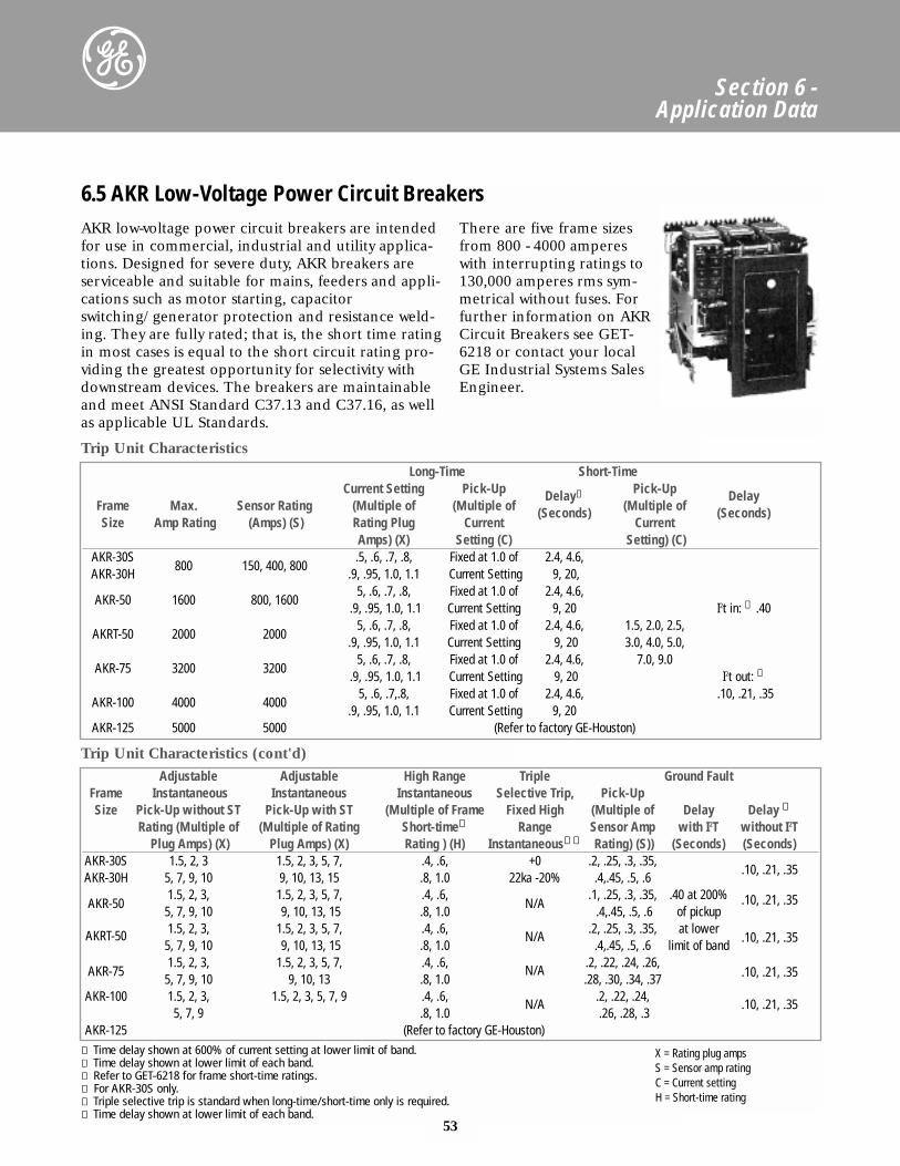
Section 6 - Application Data
6.5 AKR Low-Voltage Power Circuit Breakers
Trip Unit Characteristics
AKR low-voltage power circuit breakers are intendedfor use in commercial, industrial and utility applica-tions. Designed for severe duty, AKR breakers areserviceable and suitable for mains, feeders and appli-cations such as motor starting, capacitorswitching/generator protection and resistance weld-ing. They are fully rated; that is, the short time ratingin most cases is equal to the short circuit rating pro-viding the greatest opportunity for selectivity withdownstream devices. The breakers are maintainableand meet ANSI Standard C37.13 and C37.16, as wellas applicable UL Standards.
There are five frame sizesfrom 800 - 4000 ampereswith interrupting ratings to130,000 amperes rms sym-metrical without fuses. Forfurther information on AKRCircuit Breakers see GET-6218 or contact your localGE Industrial Systems SalesEngineer.
Adjustable Adjustable High Range Triple Ground FaultFrame Instantaneous Instantaneous Instantaneous Selective Trip, Pick-UpSize Pick-Up without ST Pick-Up with ST (Multiple of Frame Fixed High (Multiple of Delay Delay ➅
Rating (Multiple of (Multiple of Rating Short-time➂ Range Sensor Amp with I2T without I2TPlug Amps) (X) Plug Amps) (X) Rating ) (H) Instantaneous➃➄ Rating) (S)) (Seconds) (Seconds)
AKR-30S 1.5, 2, 3 1.5, 2, 3, 5, 7, .4, .6, +0 .2, .25, .3, .35,.10, .21, .35
AKR-30H 5, 7, 9, 10 9, 10, 13, 15 .8, 1.0 22ka -20% .4,.45, .5, .6
AKR-501.5, 2, 3, 1.5, 2, 3, 5, 7, .4, .6,
N/A.1, .25, .3, .35, .40 at 200%
5, 7, 9, 10 9, 10, 13, 15 .8, 1.0 .4,.45, .5, .6 of pickup.10, .21, .35
AKRT-50 1.5, 2, 3, 1.5, 2, 3, 5, 7, .4, .6, .2, .25, .3, .35, at lower .10, .21, .35
5, 7, 9, 10 9, 10, 13, 15 .8, 1.0N/A
.4,.45, .5, .6 limit of band
AKR-751.5, 2, 3, 1.5, 2, 3, 5, 7, .4, .6, .2, .22, .24, .26,
5, 7, 9, 10 9, 10, 13 .8, 1.0N/A
.28, .30, .34, .37 .10, .21, .35
AKR-100 1.5, 2, 3, 1.5, 2, 3, 5, 7, 9 .4, .6, .2, .22, .24,5, 7, 9 .8, 1.0
N/A.26, .28, .3
.10, .21, .35
AKR-125 (Refer to factory GE-Houston)
Trip Unit Characteristics (cont'd)
Long-Time Short-TimeCurrent Setting Pick-Up Delay① Pick-Up Delay
Frame Max. Sensor Rating (Multiple of (Multiple of (Seconds) (Multiple of (Seconds)Size Amp Rating (Amps) (S) Rating Plug Current Current
Amps) (X) Setting (C) Setting) (C)AKR-30S
800 150, 400, 800.5, .6, .7, .8, Fixed at 1.0 of 2.4, 4.6,
AKR-30H .9, .95, 1.0, 1.1 Current Setting 9, 20,
AKR-50 1600 800, 16005, .6, .7, .8, Fixed at 1.0 of 2.4, 4.6,
.9, .95, 1.0, 1.1 Current Setting 9, 20 I2t in: ① .40
AKRT-50 2000 20005, .6, .7, .8, Fixed at 1.0 of 2.4, 4.6, 1.5, 2.0, 2.5,
.9, .95, 1.0, 1.1 Current Setting 9, 20 3.0, 4.0, 5.0,
AKR-75 3200 32005, .6, .7, .8, Fixed at 1.0 of 2.4, 4.6, 7.0, 9.0
.9, .95, 1.0, 1.1 Current Setting 9, 20 I2t out: ➁
AKR-100 4000 40005, .6, .7,.8, Fixed at 1.0 of 2.4, 4.6, .10, .21, .35
.9, .95, 1.0, 1.1 Current Setting 9, 20AKR-125 5000 5000 (Refer to factory GE-Houston)
① Time delay shown at 600% of current setting at lower limit of band.➁ Time delay shown at lower limit of each band.➂ Refer to GET-6218 for frame short-time ratings.➃ For AKR-30S only.➄ Triple selective trip is standard when long-time/short-time only is required.➅ Time delay shown at lower limit of each band.
X = Rating plug ampsS = Sensor amp ratingC = Current settingH = Short-time rating
53
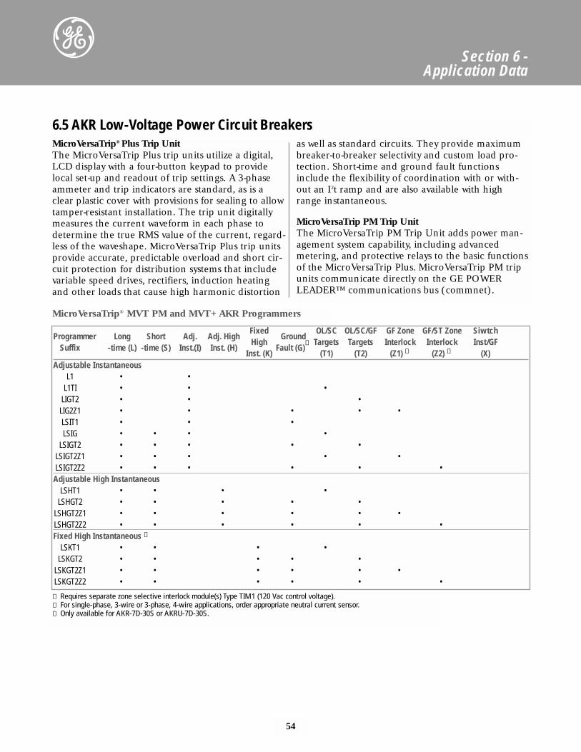
54
Section 6 - Application Data
MicroVersaTrip® Plus Trip UnitThe MicroVersaTrip Plus trip units utilize a digital,LCD display with a four-button keypad to providelocal set-up and readout of trip settings. A 3-phaseammeter and trip indicators are standard, as is aclear plastic cover with provisions for sealing to allowtamper-resistant installation. The trip unit digitallymeasures the current waveform in each phase todetermine the true RMS value of the current, regard-less of the waveshape. MicroVersaTrip Plus trip unitsprovide accurate, predictable overload and short cir-cuit protection for distribution systems that includevariable speed drives, rectifiers, induction heatingand other loads that cause high harmonic distortion
as well as standard circuits. They provide maximumbreaker-to-breaker selectivity and custom load pro-tection. Short-time and ground fault functionsinclude the flexibility of coordination with or with-out an I2t ramp and are also available with highrange instantaneous.
MicroVersaTrip PM Trip UnitThe MicroVersaTrip PM Trip Unit adds power man-agement system capability, including advancedmetering, and protective relays to the basic functionsof the MicroVersaTrip Plus. MicroVersaTrip PM tripunits communicate directly on the GE POWERLEADER™ communications bus (commnet).
6.5 AKR Low-Voltage Power Circuit Breakers
MicroVersaTrip® MVT PM and MVT+ AKR Programmers
Programmer Long Short Adj. Adj. HighFixed
GroundOL/SC OL/SC/GF GF Zone GF/ST Zone Siwtch
Suffix -time (L) -time (S) Inst.(I) Inst. (H)High
Fault (G)➁ Targets Targets Interlock Interlock Inst/GF
Inst. (K) (T1) (T2) (Z1) ① (Z2) ① (X)Adjustable Instantaneous
L1 • •L1TI • • •
LIGT2 • • •LIG2Z1 • • • • •LSIT1 • • •LSIG • • • •
LSIGT2 • • • • •LSIGT2Z1 • • • • •LSIGT2Z2 • • • • • •
Adjustable High InstantaneousLSHT1 • • • •
LSHGT2 • • • • •LSHGT2Z1 • • • • • •LSHGT2Z2 • • • • • •Fixed High Instantaneous ➂
LSKT1 • • • •LSKGT2 • • • • •
LSKGT2Z1 • • • • • •LSKGT2Z2 • • • • • •
① Requires separate zone selective interlock module(s) Type TIM1 (120 Vac control voltage).➁ For single-phase, 3-wire or 3-phase, 4-wire applications, order appropriate neutral current sensor.➂ Only available for AKR-7D-30S or AKRU-7D-30S.
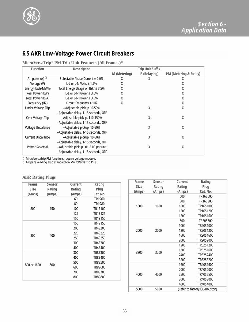
55
Section 6 - Application Data
6.5 AKR Low-Voltage Power Circuit Breakers
Function Description Trip Unit SuffixM (Metering) P (Relaying) PM (Metering & Relay)
Amperes (A) ➁ Selectable Phase Current ± 2.0% X X XVoltage (V) L-L or L-N Volts ± 1.5% X X
Energy (kwh/MWh) Total Energy Usage on Brkr ± 3.5% X XReal Power (kW) L-L or L-N Power ± 3.5% X XTotal Power (kVA) L-L or L-N Power ± 3.5% X X
Frequency (HZ) Circuit Frequency ± 1HZ X XUnder Voltage Trip --Adjustable pickup 10-50% X X
--Adjustable delay, 1-15 seconds, OFFOver Voltage Trip --Adjustable pickup, 110-150% X X
--Adjustable delay, 1-15 seconds, OFFVoltage Unbalance --Adjustable pickup, 10-50% X X
--Adjustable delay, 1-15 seconds, OFFCurrent Unbalance --Adjustable pickup, 10-50% X X
--Adjustable delay, 1-15 seconds, OFFPower Reversal --Adjustable pickup, .01-3.00 per unit X X
--Adjustable delay, 1-15 seconds, OFF
MicroVersaTrip® PM Trip Unit Features (All Frames)➀
AKR Rating Plugs
➀ MicroVersaTrip PM functions require voltage module.➁ Ampere reading also standard on MicroVersaTrip Plus.
Frame Sensor Current RatingSize Rating Rating Plug
(Amps) (Amps) (Amps) Cat. No.60 TR1S6080 TR1S80
800 150 100 TR1S100125 TR1S125150 TR1S150150 TR4S150200 TR4S200
800 400225 TR4S225250 TR4S250300 TR4S300400 TR4S400300 TR8S300400 TR8S400
800 or 1600 800500 TR8S500600 TR8S600700 TR8S700800 TR8S800
Frame Sensor Current RatingSize Rating Rating Plug
(Amps) (Amps) (Amps) Cat. No.600 TR16S600800 TR16S800
1600 1600 1000 TR16S10001200 TR16S12001600 TR16S1600800 TR20S8001000 TR20S1000
2000 2000 1200 TR20S12001600 TR20S16002000 TR20S20001200 TR32S1200
3200 32001600 TR32S16002400 TR32S24003200 TR32S32001600 TR40S16002000 TR40S2000
4000 4000 2500 TR40S25003000 TR40S30004000 TR40S4000
5000 5000 (Refer to factory GE-Houston)
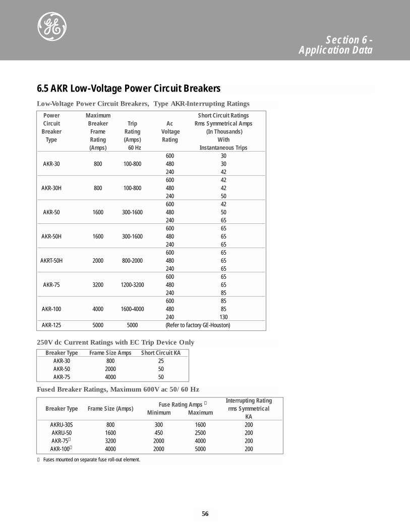
56
Section 6 - Application Data
Power Maximum Short Circuit RatingsCircuit Breaker Trip Ac Rms Symmetrical Amps
Breaker Frame Rating Voltage (In Thousands)Type Rating (Amps) Rating With
(Amps) 60 Hz Instantaneous Trips600 30
AKR-30 800 100-800 480 30240 42600 42
AKR-30H 800 100-800 480 42240 50600 42
AKR-50 1600 300-1600 480 50240 65600 65
AKR-50H 1600 300-1600 480 65240 65600 65
AKRT-50H 2000 800-2000 480 65240 65600 65
AKR-75 3200 1200-3200 480 65240 85600 85
AKR-100 4000 1600-4000 480 85240 130
AKR-125 5000 5000 (Refer to factory GE-Houston)
6.5 AKR Low-Voltage Power Circuit Breakers
Breaker Type Frame Size Amps Short Circuit KAAKR-30 800 25AKR-50 2000 50AKR-75 4000 50
Fuse Rating Amps ①Interrupting Rating
Breaker Type Frame Size (Amps)Minimum Maximum
rms Symmetrical KA
AKRU-30S 800 300 1600 200AKRU-50 1600 450 2500 200AKR-75① 3200 2000 4000 200AKR-100① 4000 2000 5000 200
Low-Voltage Power Circuit Breakers, Type AKR-Interrupting Ratings
250V dc Current Ratings with EC Trip Device Only
Fused Breaker Ratings, Maximum 600V ac 50/60 Hz
① Fuses mounted on separate fuse roll-out element.
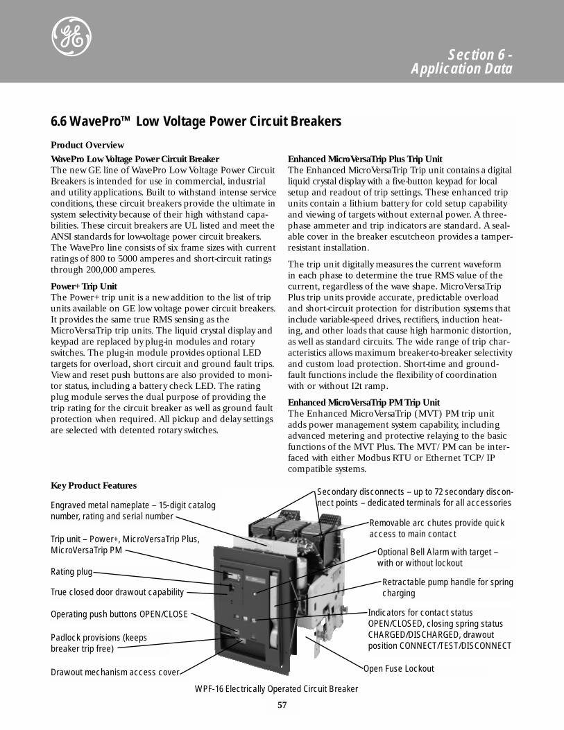
6.6 WavePro™ Low Voltage Power Circuit Breakers
Product Overview
57
Section 6 - Application Data
WavePro Low Voltage Power Circuit BreakerThe new GE line of WavePro Low Voltage Power CircuitBreakers is intended for use in commercial, industrialand utility applications. Built to withstand intense serviceconditions, these circuit breakers provide the ultimate insystem selectivity because of their high withstand capa-bilities. These circuit breakers are UL listed and meet theANSI standards for low-voltage power circuit breakers.The WavePro line consists of six frame sizes with currentratings of 800 to 5000 amperes and short-circuit ratingsthrough 200,000 amperes.
Power+ Trip UnitThe Power+ trip unit is a new addition to the list of tripunits available on GE low voltage power circuit breakers.It provides the same true RMS sensing as theMicroVersaTrip trip units. The liquid crystal display andkeypad are replaced by plug-in modules and rotaryswitches. The plug-in module provides optional LED targets for overload, short circuit and ground fault trips.View and reset push buttons are also provided to moni-tor status, including a battery check LED. The ratingplug module serves the dual purpose of providing thetrip rating for the circuit breaker as well as ground faultprotection when required. All pickup and delay settingsare selected with detented rotary switches.
Enhanced MicroVersaTrip Plus Trip UnitThe Enhanced MicroVersaTrip Trip unit contains a digitalliquid crystal display with a five-button keypad for localsetup and readout of trip settings. These enhanced tripunits contain a lithium battery for cold setup capabilityand viewing of targets without external power. A three-phase ammeter and trip indicators are standard. A seal-able cover in the breaker escutcheon provides a tamper-resistant installation.
The trip unit digitally measures the current waveform in each phase to determine the true RMS value of thecurrent, regardless of the wave shape. MicroVersaTripPlus trip units provide accurate, predictable overloadand short-circuit protection for distribution systems thatinclude variable-speed drives, rectifiers, induction heat-ing, and other loads that cause high harmonic distortion,as well as standard circuits. The wide range of trip char-acteristics allows maximum breaker-to-breaker selectivityand custom load protection. Short-time and ground-fault functions include the flexibility of coordinationwith or without I2t ramp.
Enhanced MicroVersaTrip PM Trip UnitThe Enhanced MicroVersaTrip (MVT) PM trip unitadds power management system capability, includingadvanced metering and protective relaying to the basicfunctions of the MVT Plus. The MVT/PM can be inter-faced with either Modbus RTU or Ethernet TCP/IPcompatible systems.
Engraved metal nameplate – 15-digit catalognumber, rating and serial number
Trip unit – Power+, MicroVersaTrip Plus,MicroVersaTrip PM
Rating plug
True closed door drawout capability
Operating push buttons OPEN/CLOSE
Padlock provisions (keepsbreaker trip free)
Drawout mechanism access cover
Secondary disconnects – up to 72 secondary discon-nect points – dedicated terminals for all accessories
Removable arc chutes provide quickaccess to main contact
Optional Bell Alarm with target –with or without lockout
Retractable pump handle for springcharging
Indicators for contact statusOPEN/CLOSED, closing spring statusCHARGED/DISCHARGED, drawoutposition CONNECT/TEST/DISCONNECT
Open Fuse Lockout
WPF-16 Electrically Operated Circuit Breaker
Key Product Features
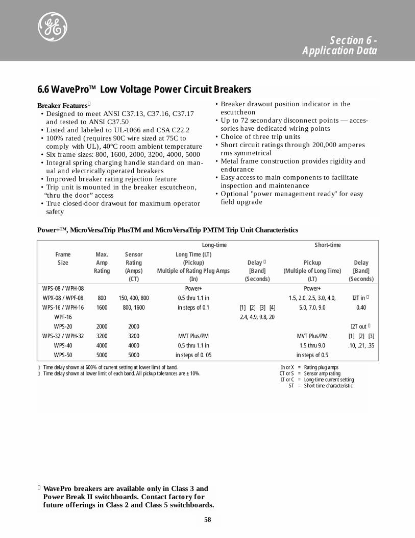
58
Section 6 - Application Data
6.6 WavePro™ Low Voltage Power Circuit Breakers
Long-time Short-time
Frame Max. Sensor Long Time (LT)Size Amp Rating (Pickup) Delay ① Pickup Delay
Rating (Amps) Multiple of Rating Plug Amps [Band] (Multiple of Long Time) [Band](CT) (In) (Seconds) (LT) (Seconds)
WPS-08 / WPH-08 Power+ Power+
WPX-08 / WPF-08 800 150, 400, 800 0.5 thru 1.1 in 1.5, 2.0, 2.5, 3.0, 4.0, I2T in ①
WPS-16 / WPH-16 1600 800, 1600 in steps of 0.1 [1] [2] [3] [4] 5.0, 7.0, 9.0 0.40
WPF-16 2.4, 4.9, 9.8, 20
WPS-20 2000 2000 I2T out ➁
WPS-32 / WPH-32 3200 3200 MVT Plus/PM MVT Plus/PM [1] [2] [3]
WPS-40 4000 4000 0.5 thru 1.1 in 1.5 thru 9.0 .10, .21, .35
WPS-50 5000 5000 in steps of 0. 05 in steps of 0.5
① Time delay shown at 600% of current setting at lower limit of band. In or X = Rating plug amps② Time delay shown at lower limit of each band. All pickup tolerances are ± 10%. CT or S = Sensor amp rating
LT or C = Long-time current settingST = Short time characteristic
Breaker Features➂
• Designed to meet ANSI C37.13, C37.16, C37.17and tested to ANSI C37.50
• Listed and labeled to UL-1066 and CSA C22.2• 100% rated (requires 90C wire sized at 75C to
comply with UL), 40°C room ambient temperature• Six frame sizes: 800, 1600, 2000, 3200, 4000, 5000• Integral spring charging handle standard on man-
ual and electrically operated breakers• Improved breaker rating rejection feature• Trip unit is mounted in the breaker escutcheon,“thru the door” access
• True closed-door drawout for maximum operatorsafety
• Breaker drawout position indicator in theescutcheon
• Up to 72 secondary disconnect points — acces-sories have dedicated wiring points
• Choice of three trip units• Short circuit ratings through 200,000 amperes
rms symmetrical• Metal frame construction provides rigidity and
endurance• Easy access to main components to facilitate
inspection and maintenance• Optional "power management ready" for easy
field upgrade
Power+™, MicroVersaTrip PlusTM and MicroVersaTrip PMTM Trip Unit Characteristics
➂ WavePro breakers are available only in Class 3 andPower Break II switchboards. Contact factory forfuture offerings in Class 2 and Class 5 switchboards.
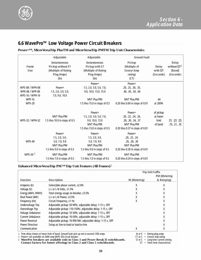
59
Section 6 - Application Data
6.6 WavePro™ Low Voltage Power Circuit Breakers
Adjustable Adjustable Ground Fault
Instantaneous Instantaneous Pickup DelayFrame Pickup without ST Pickup with ST (Multiple of Delay without I2T①
Size (Multiple of Rating (Multiple of Rating Sensor Amp with I2T [Band]Plug Amps) Plug Amps) rating) (Seconds) (Seconds)
(In) (In) (CT)
Power+ Power+WPS-08 / WPH-08 Power+ 1.5, 2.0, 3.0, 5.0, 7.0, .20, .25, .30, .35,WPX-08 / WPF-08 1.5, 2.0, 3.0, 5.0, 9.0, 10.0, 13.0, 15.0 .40, .45, .50, .60WPS-16 / WPH-16 7.0, 9.0, 10.0
WPF-16 MVT Plus/PM MVT Plus/PM .44WPS-20 1.5 thru 15.0 in steps of 0.5 0.20 thru 0.60 in steps of 0.01 at 200%
Power+ Power+ of pickupMVT Plus/PM 1.5, 2.0, 3.0, 5.0, 7.0, .20, .22, .24, .26, at lower
WPS-32 / WPH-32 1.5 thru 10.0 in steps of 0.5 9.0, 10.0, 13.0 .28, .30, .34, .37 limit [1] [2] [3]MVT Plus/PM MVT Plus/PM of band .10, .21, .35
1.5 thru 13.0 in steps of 0.5 0.20 thru 0.37 in steps of 0.01
Power+ Power+ Power+1.5, 2.0, 3.0, 1.5, 2.0, 3.0, .20, .22, .24,
WPS-40 5.0, 7.0, 9.0 5.0, 7.0, 9.0 .26, .28, .30MVT Plus/PM MVT Plus/PM MVT Plus/PM
1.5 thru 9.0 in steps of 0.5 1.5 thru 9.0 in steps of 0.5 0.20 thru 0.30 in steps of 0.01
WPS-50 ② MVT Plus/PM MVT Plus/PM MVT Plus/PM1.5 thru 7.0 in steps of 0.5 1.5 thru 7.0 in steps of 0.5 0.20 thru 0.24 in steps of 0.01
① Time delay shown at lower limit of band. Ground fault pick up not to exceed 1200 amps. In or X = Rating plug amps② Power+ not available on 5000 amp (WPS-50) circuit breaker. CT or S = Sensor amp rating➂ WavePro breakers are available only in Class 3 and Power Break II switchboards. LT or C = Long-time current setting
Contact factory for future offerings in Class 2 and Class 5 switchboards. ST = Short time characteristic
Power+™, MicroVersaTrip PlusTM and MicroVersaTrip PMTM Trip Unit Characteristics
Trip Unit SuffixPM (Metering
Function Description M (Metering) & Relaying)
Amperes (A) Selectable phase current, ±2.0% X XVoltage (V) L-L or L-N Volts, ±1.5% X XEnergy (kWh, MWh) Total energy usage on breaker, ±3.5% X XReal Power (kW) L-L or L-N Power, ±3.5% X XFrequency (Hz) Circuit Frequency, ±1 Hz X XUndervoltage Trip Adjustable pickup: 50-90%; adjustable delay: 1-15 s, OFF XOvervoltage Trip Adjustable pickup: 110-150%; adjustable delay: 1-15 s, OFF XVoltage Unbalance Adjustable pickup: 10-50%; adjustable delay: 1-15 s, OFF XCurrent Unbalance Adjustable pickup: 10-50%; adjustable delay: 1-15 s, OFF XPower Reversal Adjustable pickup: 10-990 kW; adjustable delay: 1-15 s, OFF XPower Direction Setup as line-to-load or load-to-line XCommunication X X
Enhanced MicroVersaTrip PM™Trip Unit Features (All Frames)➂
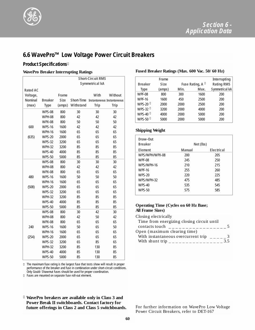
60
Section 6 - Application Data
6.6 WavePro™ Low Voltage Power Circuit Breakers
Shipping Weight
Operating Time (Cycles on 60 Hz Base; All Frame Sizes)
Short-Circuit RMS Symmetrical kA
Rated AC Voltage, Frame With WithoutNominal Breaker Size Short-Time Instantaneous Instantaneous
(max) Type (amps) Withstand Trip Trip
WPS-08 800 30 30 30WPH-08 800 42 42 42WPX-08 800 50 50 50
600 WPS-16 1600 42 42 42WPH-16 1600 65 65 65
(635) WPS-20 2000 65 65 65WPS-32 3200 65 65 65WPH-32 3200 85 85 85WPS-40 4000 85 85 85WPS-50 5000 85 85 85WPS-08 800 30 30 30WPH-08 800 42 42 42WPX-08 800 65 65 65
480 WPS-16 1600 50 50 50WPH-16 1600 65 65 65
(508) WPS-20 2000 65 65 65WPS-32 3200 65 65 65WPH-32 3200 85 85 85WPS-40 4000 85 85 85WPS-50 5000 85 85 85WPS-08 800 30 42 30WPH-08 800 42 50 42WPX-08 800 65 65 65
240 WPS-16 1600 50 65 50WPH-16 1600 65 65 65
(254) WPS-20 2000 65 65 65WPS-32 3200 65 85 65WPH-32 3200 85 130 85WPS-40 4000 85 130 85WPS-50 5000 85 130 85
Frame Interrupting Breaker Size Fuse Rating, A ① Rating RMS
Type (amps) Min. Max. Symmetrical kAWPF-08 800 300 1600 200WPF-16 1600 450 2500 200WPS-20 ② 2000 2000 2500 200WPS-32 ② 3200 2000 4000 200WPS-40 ② 4000 2000 5000 200WPS-50 ② 5000 2000 5000 200
① The maximum fuse rating is the largest fuse that tests show will result in properperformance of the breaker and fuse in combination under short-circuit conditions.Only Gould- Shawmut fuses should be used for proper coordination.
② Fuses are mounted on separate fuse roll-out element.
➂ WavePro breakers are available only in Class 3 andPower Break II switchboards. Contact factory forfuture offerings in Class 2 and Class 5 switchboards.
Draw-Out Breaker Net (lbs)
Element Manual ElectricalWPS/WPH/WPX-08 200 205WPF-08 245 250WPS/WPH-16 210 215WPF-16 255 260WPS-20 220 225WPS/WPH-32 475 485WPS-40 535 545WPS-50 575 585
Closing electricallyTime from energizing closing circuit until contacts touch _ _ _ _ _ _ _ _ _ _ _ _ _ _ _ _ _ 5
Open (maximum clearing time)With instantaneous overcurrent trip _ _ _ _ _ 3With shunt trip _ _ _ _ _ _ _ _ _ _ _ _ _ _ _ _ 3.5
For further information on WavePro Low VoltagePower Circuit Breakers, refer to DET-167
Product Specifications➂
WavePro Breaker Interrupting Ratings Fused Breaker Ratings (Max. 600 Vac. 50/60 Hz)
61
Section 6 - Application Data
High Pressure Contact SwitchesGE type HPC switches are UL Listed in accordancewith Standard 977, Fused Power Circuit Devices.
The overcenter toggle mechanism provides storedenergy, quick-make/quick-break operation. Multiplespring-loaded, high-pressure current-carrying con-tacts and an arcingcontact arm provide excellent cur-rent carrying capability without sacrificing high inter-rupting fault performance. These switches can inter-rupt, on a make and break basis, a minimum of 12times their nameplates rating without fuse assistanceat 600 volts ac. Complete HPC switch and Class Lfuse coordination is therefore achieved for all levelsof fault current up to 200,000 rms amperes symmet-rical at 600 volts ac maximum. Type HPC switchesused as service disconnects comply with the NationalElectrical Code Section 230-65 for adequate short-cir-cuit current and ground-fault protection.
• High durability, safety of operation - High dielec-tric strength. Glass-reinforced insulating case.
• High interrupting capability - Arc chute of uniqueconstruction suppresses arcs and cools gases rap-idly, providing quick arc interrupting and extend-ed switch life.
• High transient voltage withstanding - Interphasepartitions mesh with switch cover to completelyisolate each pole.
• Extended switch life - Preloaded constant pressurepivot eliminates braid whip and fraying on highshort-circuit currents and repeated operations.
• Positive "On-Off" indication - Green (Off), red(On), eliminates any question about the positionof the switch contacts.
• Easy operation - Quick Make - Extra heavy duty,low torque rotary-operated closing mechanism. L-handle 800-1600 amperes; T-handle 2000 amperesand above.
• Emergency Open - Quick Break - Fingertip "Off"button instantly opens the switch contacts.
• Positive door and switch interlock - Separate fuseaccess door is not required.
Product Forms• Top Feed - Line terminals at top of switch.• Bottom Feed - Line terminals at bottom of switch;
fuses are de-energized when switch is in Off posi-tion. Same size switchboard as top feed. Whenswitchboard is bottom fed it permits shallowdesign. Space for running feed to top terminals isnot required.
Options AvailableManual Operation - For manual, high-interruptingcapacity, disconnects not requiring remote trippingand/or ground-fault protection.
Integral Ground Fault - Incorporates a solid-state,inverse-time and fixed-time response. Ground faultfunction is self-powered and has field adjustableground fault current and delay time settings for max-imum coordination and selectivity. Through 3000amperes, switches with integral ground fault are thesame size as manual switches.
Electric Trip - For remote tripping or for use withGroundBreak® components. All electric trip switchesare the same size as manual devices.
Blown-fuse Protector - Provides single phase protec-tion by tripping switch when a fuze blows or whenswitch is closed with a blown fuse or no fuseinstalled. Suitable for system voltage of 208-480 voltsac. Mounted internally. Does not provide protectionof voltage loss of the power source.
Auxiliary Switch - Provides remote indication ofmain contact position. Switch elements are Type AB,single pole, double-throw. Switch element ratingsare: 0.25A at 250Vdc; 0.5A at 125Vdc; 6.0 Amps at240Vac.
1. Mechanical Indicator-protrudes when ground faultoccurs.
2. Field Adjustable Ground Fault Trip Point - from200 to 100 amperes in six steps.
3. Field Adjustable Ground Fault Delay Time - min.(0.03 sec), intermediate (0.20 sec) and max (0.50sec) delay time settings.
4. No Trip Test Button - permits ground fault systemcheck without tripping switch.
5. Test Button - simulates an actual ground fault andwill trip switch unless "No Trip" button isdepressed prior to pushing test button. Groundfault indicator will protrude when system is testedor when actual ground fault occurs.
Note: Although the integral ground fault function isself-powered, the test function does require anexternal 120Vac (200VA nominal) controlpower source.
6.7 High Pressure Contact Switches
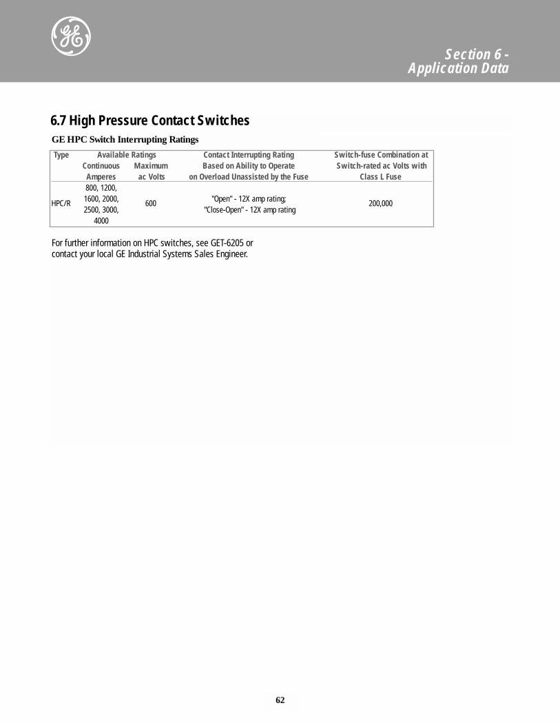
62
Section 6 - Application Data
6.7 High Pressure Contact Switches
Type Available Ratings Contact Interrupting Rating Switch-fuse Combination atContinuous Maximum Based on Ability to Operate Switch-rated ac Volts with
Amperes ac Volts on Overload Unassisted by the Fuse Class L Fuse800, 1200,
HPC/R 1600, 2000, 600 "Open" - 12X amp rating; 200,0002500, 3000, "Close-Open" - 12X amp rating
4000
GE HPC Switch Interrupting Ratings
For further information on HPC switches, see GET-6205 orcontact your local GE Industrial Systems Sales Engineer.
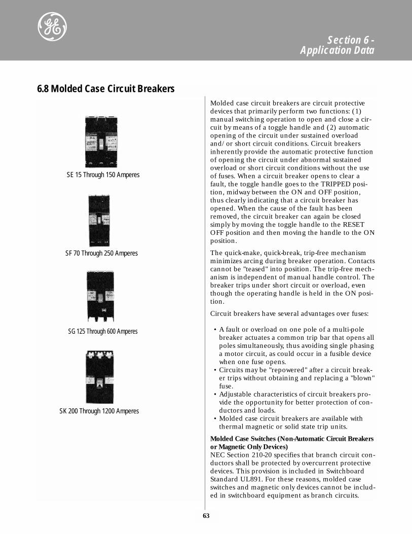
63
Section 6 - Application Data
Molded case circuit breakers are circuit protectivedevices that primarily perform two functions: (1)manual switching operation to open and close a cir-cuit by means of a toggle handle and (2) automaticopening of the circuit under sustained overloadand/or short circuit conditions. Circuit breakersinherently provide the automatic protective functionof opening the circuit under abnormal sustainedoverload or short circuit conditions without the useof fuses. When a circuit breaker opens to clear afault, the toggle handle goes to the TRIPPED posi-tion, midway between the ON and OFF position,thus clearly indicating that a circuit breaker hasopened. When the cause of the fault has beenremoved, the circuit breaker can again be closedsimply by moving the toggle handle to the RESETOFF position and then moving the handle to the ONposition.
The quick-make, quick-break, trip-free mechanismminimizes arcing during breaker operation. Contactscannot be "teased" into position. The trip-free mech-anism is independent of manual handle control. Thebreaker trips under short circuit or overload, eventhough the operating handle is held in the ON posi-tion.
Circuit breakers have several advantages over fuses:
• A fault or overload on one pole of a multi-polebreaker actuates a common trip bar that opens allpoles simultaneously, thus avoiding single phasinga motor circuit, as could occur in a fusible devicewhen one fuse opens.
• Circuits may be "repowered" after a circuit break-er trips without obtaining and replacing a "blown"fuse.
• Adjustable characteristics of circuit breakers pro-vide the opportunity for better protection of con-ductors and loads.
• Molded case circuit breakers are available withthermal magnetic or solid state trip units.
Molded Case Switches (Non-Automatic Circuit Breakersor Magnetic Only Devices)NEC Section 210-20 specifies that branch circuit con-ductors shall be protected by overcurrent protectivedevices. This provision is included in SwitchboardStandard UL891. For these reasons, molded caseswitches and magnetic only devices cannot be includ-ed in switchboard equipment as branch circuits.
6.8 Molded Case Circuit Breakers
SE 15 Through 150 Amperes
SF 70 Through 250 Amperes
SG 125 Through 600 Amperes
SK 200 Through 1200 Amperes
64
Section 6 - Application Data
Molded case switch requirements for main devicesmust be reviewed by application engineering.
Current Limiting Circuit Breaker (Fuseless)Current limiting circuit breakers (fuseless) use athermal trip that protects against overloads and amagnetic trip to guard against moderate short cir-cuits. The circuit breakers, when operating withintheir current limiting range, limit the let-through(I2t) and peak current (Ip) to a value less than thatof a 1/2 cycle-wave of the available short circuit cur-rent. They are available in the following frame stylesand ratings:
• THLC1: 15-150 amps• THLC2: 125-225 amps• THLC4: 250-400 amps• SELA, SEPA: 15-150 amps• SFLA, SFPA: 70-250 amps• SGLA, SGPA: 125-600 amps
Digital, Solid State Spectra RMS™ BreakersSpectra RMS circuit breakers are available in fourframe sizes and meet UL Standard 489, InternationalElectrotechnical Commission (IEC) Standard 947.2,and Japanese Industrial Standard (JIS) No. C83370.The trip units employ digital sampling techniques toaccurately determine the true RMS heating value ofthe load current. These devices include the followingfeatures:
• UL Listed current limiting capability in a 150Athrough 600A frame.
• UL Listed for reverse feed applications.• Field interchangeable rating plugs.• Field installable control accessories - shunt trip,
UV release, auxiliary switch and bell alarm switch.• Field adjustment of the instantaneous characteris-
tics, which include a tracking short-time functionand current setting values.
• Interrupting Ratings to 200,000A RMS at 240Vand 100,000A RMS at 480V.
• 100% Rated Devices in the G & K frames with tripratings of 125 - 1000A.
6.8 Molded Case Circuit Breakers
For further information on Spectra RMS circuit breakers, seeGET-7002 or contact your local GE Industrial Systems SalesEngineer.
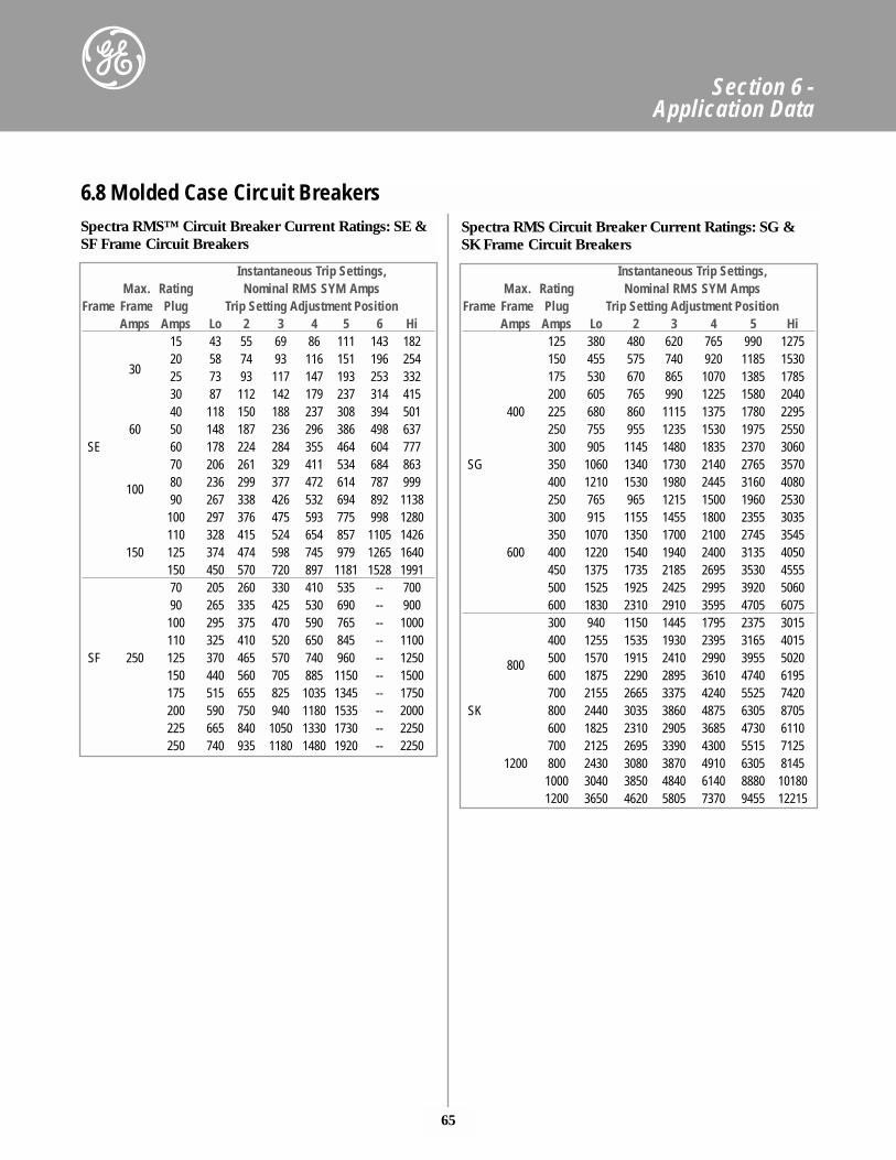
65
Section 6 - Application Data
Instantaneous Trip Settings, Max. Rating Nominal RMS SYM Amps
Frame Frame Plug Trip Setting Adjustment PositionAmps Amps Lo 2 3 4 5 6 Hi
15 43 55 69 86 111 143 18220 58 74 93 116 151 196 254
30 25 73 93 117 147 193 253 33230 87 112 142 179 237 314 41540 118 150 188 237 308 394 501
60 50 148 187 236 296 386 498 637SE 60 178 224 284 355 464 604 777
70 206 261 329 411 534 684 863
100 80 236 299 377 472 614 787 99990 267 338 426 532 694 892 1138100 297 376 475 593 775 998 1280110 328 415 524 654 857 1105 1426
150 125 374 474 598 745 979 1265 1640150 450 570 720 897 1181 1528 199170 205 260 330 410 535 -- 70090 265 335 425 530 690 -- 900100 295 375 470 590 765 -- 1000110 325 410 520 650 845 -- 1100
SF 250 125 370 465 570 740 960 -- 1250150 440 560 705 885 1150 -- 1500175 515 655 825 1035 1345 -- 1750200 590 750 940 1180 1535 -- 2000225 665 840 1050 1330 1730 -- 2250250 740 935 1180 1480 1920 -- 2250
6.8 Molded Case Circuit BreakersSpectra RMS™ Circuit Breaker Current Ratings: SE &SF Frame Circuit Breakers
Instantaneous Trip Settings, Max. Rating Nominal RMS SYM Amps
Frame Frame Plug Trip Setting Adjustment PositionAmps Amps Lo 2 3 4 5 Hi
125 380 480 620 765 990 1275150 455 575 740 920 1185 1530175 530 670 865 1070 1385 1785200 605 765 990 1225 1580 2040
400 225 680 860 1115 1375 1780 2295250 755 955 1235 1530 1975 2550300 905 1145 1480 1835 2370 3060
SG 350 1060 1340 1730 2140 2765 3570400 1210 1530 1980 2445 3160 4080250 765 965 1215 1500 1960 2530300 915 1155 1455 1800 2355 3035350 1070 1350 1700 2100 2745 3545
600 400 1220 1540 1940 2400 3135 4050450 1375 1735 2185 2695 3530 4555500 1525 1925 2425 2995 3920 5060600 1830 2310 2910 3595 4705 6075300 940 1150 1445 1795 2375 3015400 1255 1535 1930 2395 3165 4015
800 500 1570 1915 2410 2990 3955 5020600 1875 2290 2895 3610 4740 6195700 2155 2665 3375 4240 5525 7420
SK 800 2440 3035 3860 4875 6305 8705600 1825 2310 2905 3685 4730 6110700 2125 2695 3390 4300 5515 7125
1200 800 2430 3080 3870 4910 6305 81451000 3040 3850 4840 6140 8880 101801200 3650 4620 5805 7370 9455 12215
Spectra RMS Circuit Breaker Current Ratings: SG &SK Frame Circuit Breakers
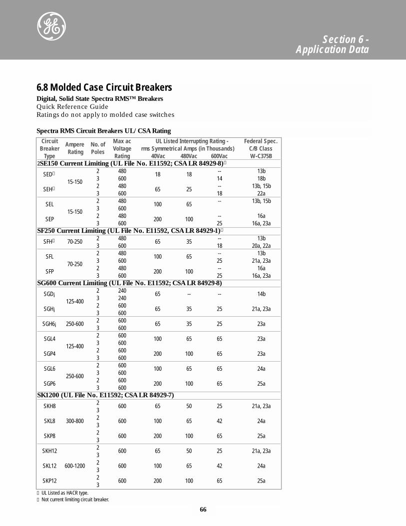
66
Section 6 - Application Data
Digital, Solid State Spectra RMS™ BreakersQuick Reference GuideRatings do not apply to molded case switches
Spectra RMS Circuit Breakers UL/CSA RatingCircuit Ampere No. of Max ac UL Listed Interrupting Rating - Federal Spec.
Breaker Rating Poles Voltage rms Symmetrical Amps (in Thousands) C/B ClassType Rating 40Vac 480Vac 600Vac W-C375B
2SE150 Current Limiting (UL File No. E11592; CSA LR 84929-8)①
SED➁ 2 480 18 18 -- 13b
15-150 3 600 14 18b
SEH➁ 2 480 65 25 -- 13b, 15b3 600 18 22a
SEL 2 480 100 65 -- 13b, 15b
15-150 3 600
SEP 2 480 200 100 -- 16a3 600 25 16a, 23a
SF250 Current Limiting (UL File No. E11592, CSA LR 84929-1)①
SFH➁ 70-250 2 480 65 35 -- 13b3 600 18 20a, 22a
SFL 2 480 100 65 -- 13b
70-250 3 600 25 21a, 23a
SFP 2 480 200 100 -- 16a3 600 25 16a, 23a
SG600 Current Limiting (UL File No. E11592; CSA LR 84929-8)
SGD¡ 2 240 65 -- -- 14b125-400 3 240
SGH¡ 2 600 65 35 25 21a, 23a3 600
SGH6¡ 250-600 2 600 65 35 25 23a3 600
SGL4 2 600 100 65 65 23a125-400 3 600
SGP4 2 600 200 100 65 23a3 600
SGL6 2 600 100 65 65 24a250-600 3 600
SGP6 2 600 200 100 65 25a3 600
SK1200 (UL File No. E11592; CSA LR 84929-7)
SKH8 2 600 65 50 25 21a, 23a3
SKL8 300-800 2 600 100 65 42 24a3
SKP8 2 600 200 100 65 25a3
SKH12 2 600 65 50 25 21a, 23a3
SKL12 600-1200 2 600 100 65 42 24a3
SKP12 2 600 200 100 65 25a3
① UL Listed as HACR type.➁ Not current limiting circuit breaker.
6.8 Molded Case Circuit Breakers
67
Section 6 - Application Data
Features and Options• Overcurrent protection
- Adjustable long-time (pickup and time delay)- Adjustable instantaneous (pickup)
• Status- Trip targets (overcurrent and short circuit)- Long-time pickup indication
• Metering display- Phase current (selectable among phases)
+24 Vdc control power is available as an option onlyon the MicroVersaTrip Plus breaker. It providespower to the display if the breaker is not energized.
The optional functions available on both theMicroVersaTrip Plus and MicroVersaTrip PM break-ers are:
• Overcurrent protection- Adjustable short-time protection (pickup and
time delay bands having I2T ramp in or I2Tramp out)
- Adjustable ground-fault protection (pickup andtime delay bands having I2T ramp in or I2Tramp out
• Status trip targets (ground fault when that option-al function is in the Trip Unit)
Additional functions available only withMicroVersaTrip PM breakers, and which require +24Vdc control power from the Power Supply Assembly,Power Supply Plate, or Voltage Module and aMicroVersaTrip PM voltage-sensing signal from theVoltage Conditioner Assembly, Voltage ConditionerPlate, or Voltage Module are:
• Metering functions- Voltage (selectable among phases or phase to
neutral)- Energy (kWh/MWh)- Real Power (kW/MW)- Apparent power (kVA/MVA)- Frequency (Hz)
• Communications- Communicate with GE POWER LEADER Power
Management System
Optional functions available only on MicroVersaTripPM Trip Units in breakers are:
• Protective relays- Undervoltage- Overvoltage- Voltage unbalance- Current unbalance- Power reversal
6.8 Molded Case Circuit Breakers
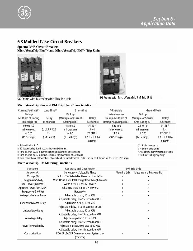
68
Section 6 - Application Data
Current Setting (C) Long Time① Short-time Adjustable Ground FaultPickup Pickup instantaneous Pickup
Multiple of Rating Delay (Multiple of Current Delay Pickup (Multiple of Multiple of Sensor DelayPlus Amps (x) (Seconds) Settings) (C) (Seconds) Rating Plug Amps) (X) Amp Rating (S) (Seconds)
0.50 to 1.0 1.5 to 9.0 I2T IN ➂ 1.5 to 10.0 0.2 to 1.0 I2T IN ➃
in increments 2.4.4.9.9.8.20 in increments 0.44 in increments in increments 0.41of 0.05 ➁➂ of 0.5 I2T OUT ⑤ of 0.5 of 0.05 I2T OUT ⑤
(11 Settings) (3-4 Bands) (16 Settings) 0.1.0.2.0.3.0.4 (18 Settings) (17 Settings) 0.1.0.2.0.3.0.4(8 Bands) (8 Bands)
Functions Accuracy and Description PM Trip UnitAmperes (A) Current ± 4% Selectable Phase Metering (M) Metering and Relaying (PM)Voltage (V) Volts ± 2% Selectable Phase in L-L or L-N á x x
Energy (kWh/MWh) Watt Hours ± 7% Total energy flow through breaker x xReal Power (kW/MW) Watts ± 6% L-L or L-N Power á x x
Apparent Power (kVA/MVA) Volt amps ± 6% L-L or L-N Power á x xFrequency (45-66 Hz) Hertz ± 6% x x
Voltage Unbalance Relay Adjustable pickup, 10 to 50% x xAdjustable delay, 1 to 15 seconds or OFF
Current Unbalance Relay Adjustable pickup, 10 to 50% xAdjustable delay, 1 to 15 seconds or OFF
Undervoltage Relay Adjustable pickup, 50 to 90% xAdjustable delay, 1 to 15 seconds or OFF
Overvoltage Relay Adjustable pickup, 110 to 150% xAdjustable delay, 1 to 15 seconds or OFF
Power Reversal Relay Adjustable pickup, 0.01 MW to 90 MW xAdjustable delay, 1 to 15 seconds or OFF
Communications POWER LEADER Communications System Link x x(common)
① Pickup fixed at 1.1C.➁ 20 Second delay (band) not available on SG frames.➂ Time delay at 600% of current setting at lower limit of each band➃ Time delay at 200% of pickup setting at the lower limit of each band.⑤ Time delay shown at lower limit of each band. Pickup tolerances ± 10%. Ground Fault Pickup not to exceed 1200 amps.
X = Rating plug ampsS = Sensor amp ratingC= Long-time current settings (Pickup)C= X times Rating Plug Amps
SG Frame with MicroVersaTrip Plus Trip Unit SG Frame with MicroVersaTrip PM Trip Unit
6.8 Molded Case Circuit BreakersSpectra RMS Circuit BreakersMicroVersaTrip Plus™ and MicroVersaTrip PM™ Trip Units
MicroVersaTrip Plus and PM Trip Unit Characteristics
MicroVersaTrip PM Metering Functions
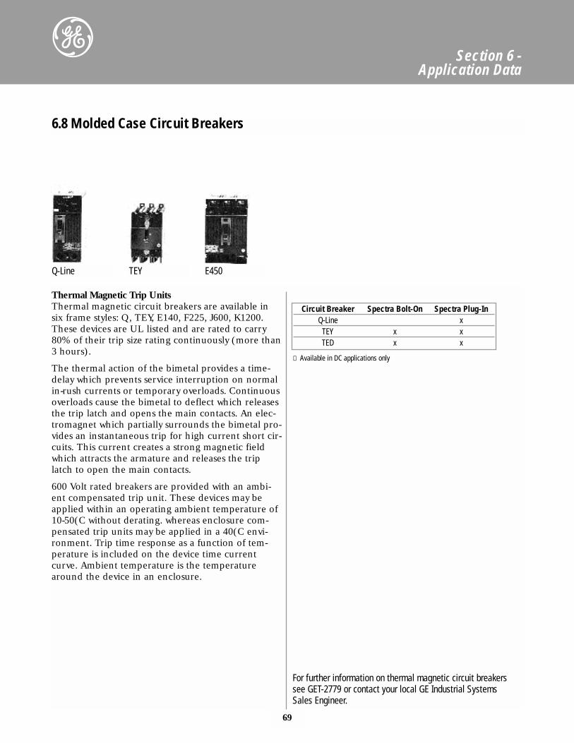
69
Section 6 - Application Data
Thermal Magnetic Trip UnitsThermal magnetic circuit breakers are available insix frame styles: Q, TEY, E140, F225, J600, K1200.These devices are UL listed and are rated to carry80% of their trip size rating continuously (more than3 hours).
The thermal action of the bimetal provides a time-delay which prevents service interruption on normalin-rush currents or temporary overloads. Continuousoverloads cause the bimetal to deflect which releasesthe trip latch and opens the main contacts. An elec-tromagnet which partially surrounds the bimetal pro-vides an instantaneous trip for high current short cir-cuits. This current creates a strong magnetic fieldwhich attracts the armature and releases the triplatch to open the main contacts.
600 Volt rated breakers are provided with an ambi-ent compensated trip unit. These devices may beapplied within an operating ambient temperature of10-50(C without derating. whereas enclosure com-pensated trip units may be applied in a 40(C envi-ronment. Trip time response as a function of tem-perature is included on the device time currentcurve. Ambient temperature is the temperaturearound the device in an enclosure.
Circuit Breaker Spectra Bolt-On Spectra Plug-InQ-Line x
TEY x xTED x x
① Available in DC applications only
6.8 Molded Case Circuit Breakers
Q-Line TEY E450
For further information on thermal magnetic circuit breakerssee GET-2779 or contact your local GE Industrial SystemsSales Engineer.
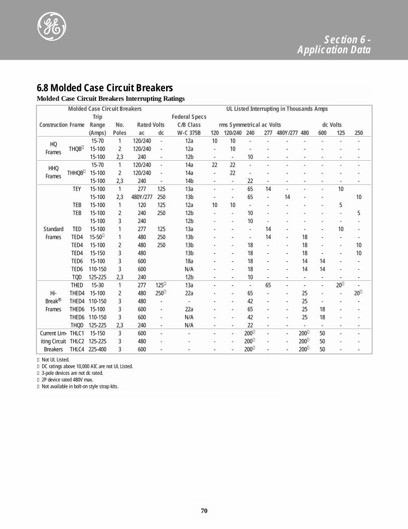
70
Section 6 - Application Data
Molded Case Circuit Breakers Interrupting RatingsMolded Case Circuit Breakers UL Listed Interrupting in Thousands Amps
Trip Federal SpecsConstruction Frame Range No. Rated Volts C/B Class rms Symmetrical ac Volts dc Volts
(Amps) Poles ac dc W-C 375B 120 120/240 240 277 480Y/277 480 600 125 250
HQ 15-70 1 120/240 - 12a 10 10 - - - - - - -
Frames THQB⑤ 15-100 2 120/240 - 12a - 10 - - - - - - -15-100 2,3 240 - 12b - - 10 - - - - - -
HHQ 15-70 1 120/240 - 14a 22 22 - - - - - - -
Frames THHQB⑤ 15-100 2 120/240 - 14a - 22 - - - - - - -15-100 2,3 240 - 14b - - 22 - - - - - -
TEY 15-100 1 277 125 13a - - 65 14 - - - 1015-100 2,3 480Y/277 250 13b - - 65 - 14 - - 10
TEB 15-100 1 120 125 12a 10 10 - - - - - 5TEB 15-100 2 240 250 12b - - 10 - - - - - 5
15-100 3 240 12b - - 10 - - - - - -Standard TED 15-100 1 277 125 13a - - - 14 - - - 10 -Frames TED4 15-50① 1 480 250 13b - - - 14 - 18 - - -
TED4 15-100 2 480 250 13b - - 18 - - 18 - - 10TED4 15-150 3 480 13b - - 18 - - 18 - - 10TED6 15-100 3 600 18a - - 18 - - 14 14 - -TED6 110-150 3 600 N/A - - 18 - - 14 14 - -TQD 125-225 2,3 240 12b - - 10 - - - - - -THED 15-30 1 277 125➂ 13a - - - 65 - - - 20➁ -
Hi- THED4 15-100 2 480 250➂ 22a - - 65 - - 25 - - 20➁
Break® THED4 110-150 3 480 - - - - 42 - - 25 - - -Frames THED6 15-100 3 600 - 22a - - 65 - - 25 18 - -
THED6 110-150 3 600 - N/A - - 42 - - 25 18 - -THQD 125-225 2,3 240 - N/A - - 22 - - - - - -
Current Lim- THLC1 15-150 3 600 - - - - 200⑤ - - 200⑤ 50 - -iting Circuit THLC2 125-225 3 480 - - - - 200⑤ - - 200⑤ 50 - -
Breakers THLC4 225-400 3 600 - - - - 200⑤ - - 200⑤ 50 - -
6.8 Molded Case Circuit Breakers
① Not UL Listed.➁ DC ratings above 10,000 AIC are not UL Listed.➂ 3-pole devices are not dc rated.➃ 2P device rated 480V max.⑤ Not available in bolt-on style strap kits.
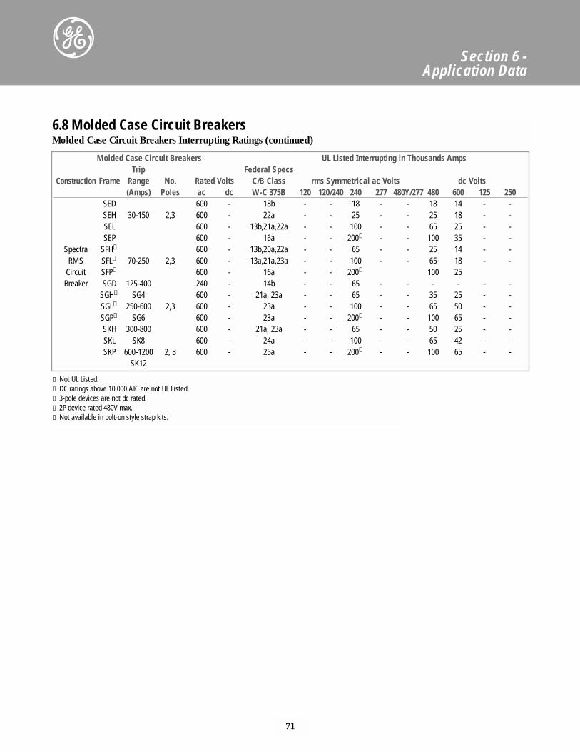
71
Section 6 - Application Data
Molded Case Circuit Breakers UL Listed Interrupting in Thousands AmpsTrip Federal Specs
Construction Frame Range No. Rated Volts C/B Class rms Symmetrical ac Volts dc Volts(Amps) Poles ac dc W-C 375B 120 120/240 240 277 480Y/277 480 600 125 250
SED 600 - 18b - - 18 - - 18 14 - -SEH 30-150 2,3 600 - 22a - - 25 - - 25 18 - -SEL 600 - 13b,21a,22a - - 100 - - 65 25 - -SEP 600 - 16a - - 200⑤ - - 100 35 - -
Spectra SFH➃ 600 - 13b,20a,22a - - 65 - - 25 14 - -RMS SFL➃ 70-250 2,3 600 - 13a,21a,23a - - 100 - - 65 18 - -
Circuit SFP➃ 600 - 16a - - 200⑤ 100 25Breaker SGD 125-400 240 - 14b - - 65 - - - - - -
SGH➃ SG4 600 - 21a, 23a - - 65 - - 35 25 - -SGL➃ 250-600 2,3 600 - 23a - - 100 - - 65 50 - -SGP➃ SG6 600 - 23a - - 200⑤ - - 100 65 - -SKH 300-800 600 - 21a, 23a - - 65 - - 50 25 - -SKL SK8 600 - 24a - - 100 - - 65 42 - -SKP 600-1200 2, 3 600 - 25a - - 200⑤ - - 100 65 - -
SK12
Molded Case Circuit Breakers Interrupting Ratings (continued)6.8 Molded Case Circuit Breakers
① Not UL Listed.➁ DC ratings above 10,000 AIC are not UL Listed.➂ 3-pole devices are not dc rated.➃ 2P device rated 480V max.⑤ Not available in bolt-on style strap kits.
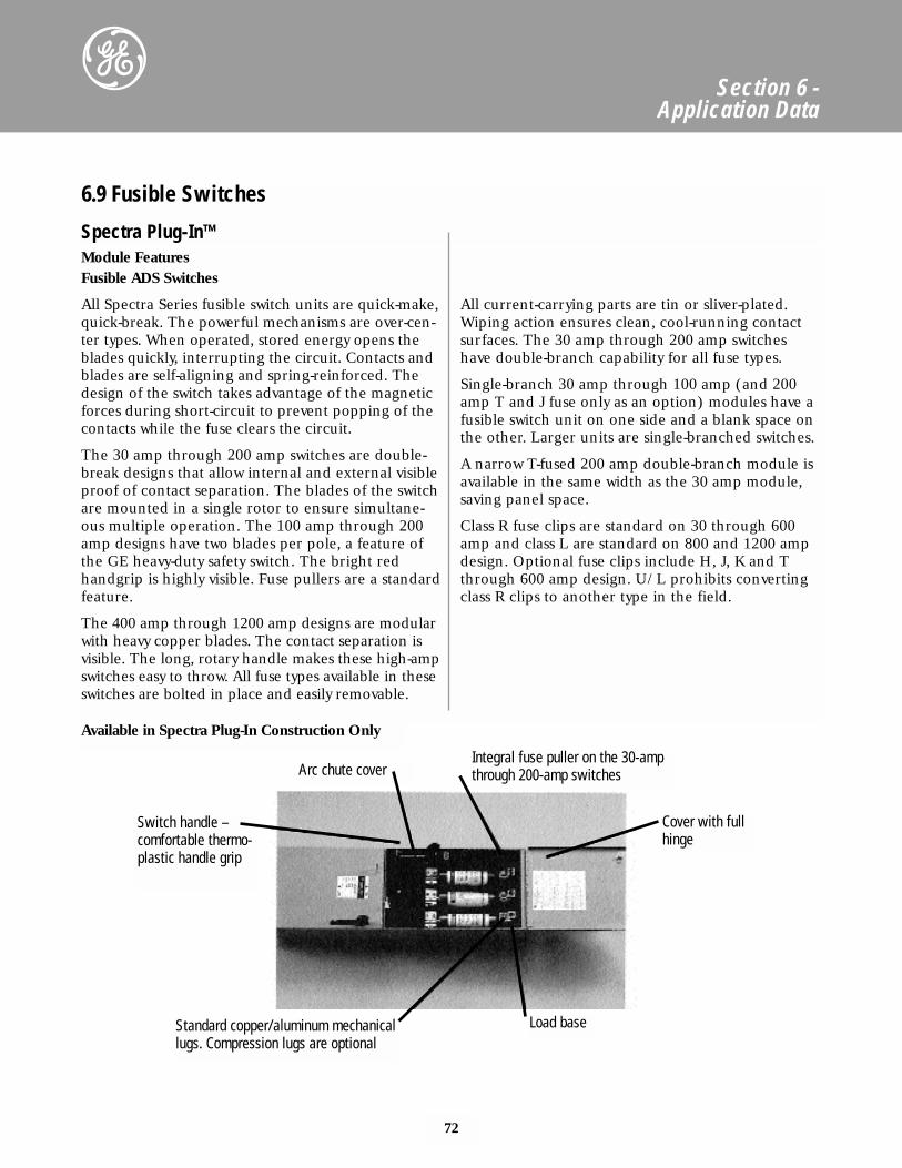
72
Section 6 - Application Data
Module FeaturesFusible ADS Switches
All Spectra Series fusible switch units are quick-make,quick-break. The powerful mechanisms are over-cen-ter types. When operated, stored energy opens theblades quickly, interrupting the circuit. Contacts andblades are self-aligning and spring-reinforced. Thedesign of the switch takes advantage of the magneticforces during short-circuit to prevent popping of thecontacts while the fuse clears the circuit.
The 30 amp through 200 amp switches are double-break designs that allow internal and external visibleproof of contact separation. The blades of the switchare mounted in a single rotor to ensure simultane-ous multiple operation. The 100 amp through 200amp designs have two blades per pole, a feature ofthe GE heavy-duty safety switch. The bright redhandgrip is highly visible. Fuse pullers are a standardfeature.
The 400 amp through 1200 amp designs are modularwith heavy copper blades. The contact separation isvisible. The long, rotary handle makes these high-ampswitches easy to throw. All fuse types available in theseswitches are bolted in place and easily removable.
All current-carrying parts are tin or sliver-plated.Wiping action ensures clean, cool-running contactsurfaces. The 30 amp through 200 amp switcheshave double-branch capability for all fuse types.
Single-branch 30 amp through 100 amp (and 200amp T and J fuse only as an option) modules have afusible switch unit on one side and a blank space onthe other. Larger units are single-branched switches.
A narrow T-fused 200 amp double-branch module isavailable in the same width as the 30 amp module,saving panel space.
Class R fuse clips are standard on 30 through 600amp and class L are standard on 800 and 1200 ampdesign. Optional fuse clips include H, J, K and Tthrough 600 amp design. U/L prohibits convertingclass R clips to another type in the field.
6.9 Fusible Switches
Spectra Plug-In™
Switch handle –comfortable thermo-plastic handle grip
Arc chute coverIntegral fuse puller on the 30-ampthrough 200-amp switches
Cover with fullhinge
Standard copper/aluminum mechanicallugs. Compression lugs are optional
Load base
Available in Spectra Plug-In Construction Only
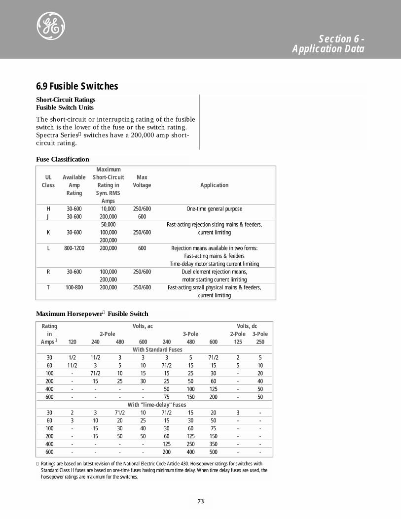
73
Section 6 - Application Data
Short-Circuit RatingsFusible Switch Units
The short-circuit or interrupting rating of the fusibleswitch is the lower of the fuse or the switch rating.Spectra Series➀ switches have a 200,000 amp short-circuit rating.
MaximumUL Available Short-Circuit Max
Class Amp Rating in Voltage ApplicationRating Sym. RMS
AmpsH 30-600 10,000 250/600 One-time general purposeJ 30-600 200,000 600
50,000 Fast-acting rejection sizing mains & feeders,K 30-600 100,000 250/600 current limiting
200,000L 800-1200 200,000 600 Rejection means available in two forms:
Fast-acting mains & feedersTime-delay motor starting current limiting
R 30-600 100,000 250/600 Duel element rejection means,200,000 motor starting current limiting
T 100-800 200,000 250/600 Fast-acting small physical mains & feeders,current limiting
Rating Volts, ac Volts, dcin 2-Pole 3-Pole 2-Pole 3-Pole
Amps① 120 240 480 600 240 480 600 125 250With Standard Fuses
30 1/2 11/2 3 3 3 5 71/2 2 560 11/2 3 5 10 71/2 15 15 5 10100 - 71/2 10 15 15 25 30 - 20200 - 15 25 30 25 50 60 - 40400 - - - - 50 100 125 - 50600 - - - - 75 150 200 - 50
With "Time-delay" Fuses30 2 3 71/2 10 71/2 15 20 3 -60 3 10 20 25 15 30 50 - -100 - 15 30 40 30 60 75 - -200 - 15 50 50 60 125 150 - -400 - - - - 125 250 350 - -600 - - - - 200 400 500 - -
① Ratings are based on latest revision of the National Electric Code Article 430. Horsepower ratings for switches withStandard Class H fuses are based on one-time fuses having minimum time delay. When time delay fuses are used, thehorsepower ratings are maximum for the switches.
6.9 Fusible Switches
Fuse Classification
Maximum Horsepower① Fusible Switch
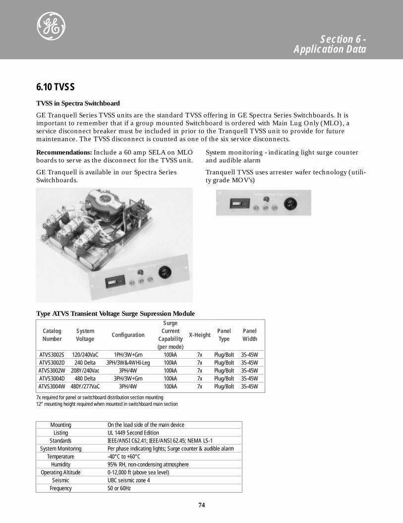
74
Section 6 - Application Data
6.10 TVSS
TVSS in Spectra Switchboard
GE Tranquell Series TVSS units are the standard TVSS offering in GE Spectra Series Switchboards. It isimportant to remember that if a group mounted Switchboard is ordered with Main Lug Only (MLO), a service disconnect breaker must be included in prior to the Tranquell TVSS unit to provide for future maintenance. The TVSS disconnect is counted as one of the six service disconnects.
Mounting On the load side of the main deviceListing UL 1449 Second Edition
Standards IEEE/ANSI C62.41; IEEE/ANSI 62.45; NEMA LS-1System Monitoring Per phase indicating lights; Surge counter & audible alarm
Temperature -40°C to +60°CHumidity 95% RH, non-condensing atmosphere
Operating Altitude 0-12,000 ft (above sea level)Seismic UBC seismic zone 4
Frequency 50 or 60Hz
SurgeCatalog System
ConfigurationCurrent
X-HeightPanel Panel
Number Voltage Capability Type Width(per mode)
ATVS3002S 120/240VaC 1PH/3W+Grn 100kA 7x Plug/Bolt 35-45WATVS3002D 240 Delta 3PH/3W&4WHI-Leg 100kA 7x Plug/Bolt 35-45WATVS3002W 208Y/240Vac 3PH/4W 100kA 7x Plug/Bolt 35-45WATVS3004D 480 Delta 3PH/3W+Grn 100kA 7x Plug/Bolt 35-45WATVS3004W 480Y/277VaC 3PH/4W 100kA 7x Plug/Bolt 35-45W
Type ATVS Transient Voltage Surge Supression Module
7x required for panel or switchboard distribution section mounting12” mounting height required when mounted in switchboard main section
Recommendations: Include a 60 amp SELA on MLOboards to serve as the disconnect for the TVSS unit.
GE Tranquell is available in our Spectra SeriesSwitchboards.
System monitoring - indicating light surge counterand audible alarm
Tranquell TVSS uses arrester wafer technology (utili-ty grade MOV’s)
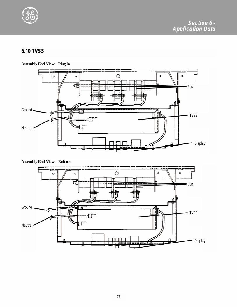
75
Section 6 - Application Data
6.10 TVSS
Bus
TVSS
Display
Neutral
Ground
Bus
TVSS
Display
Neutral
Ground
Assembly End View – Plug-in
Assembly End View – Bolt-on
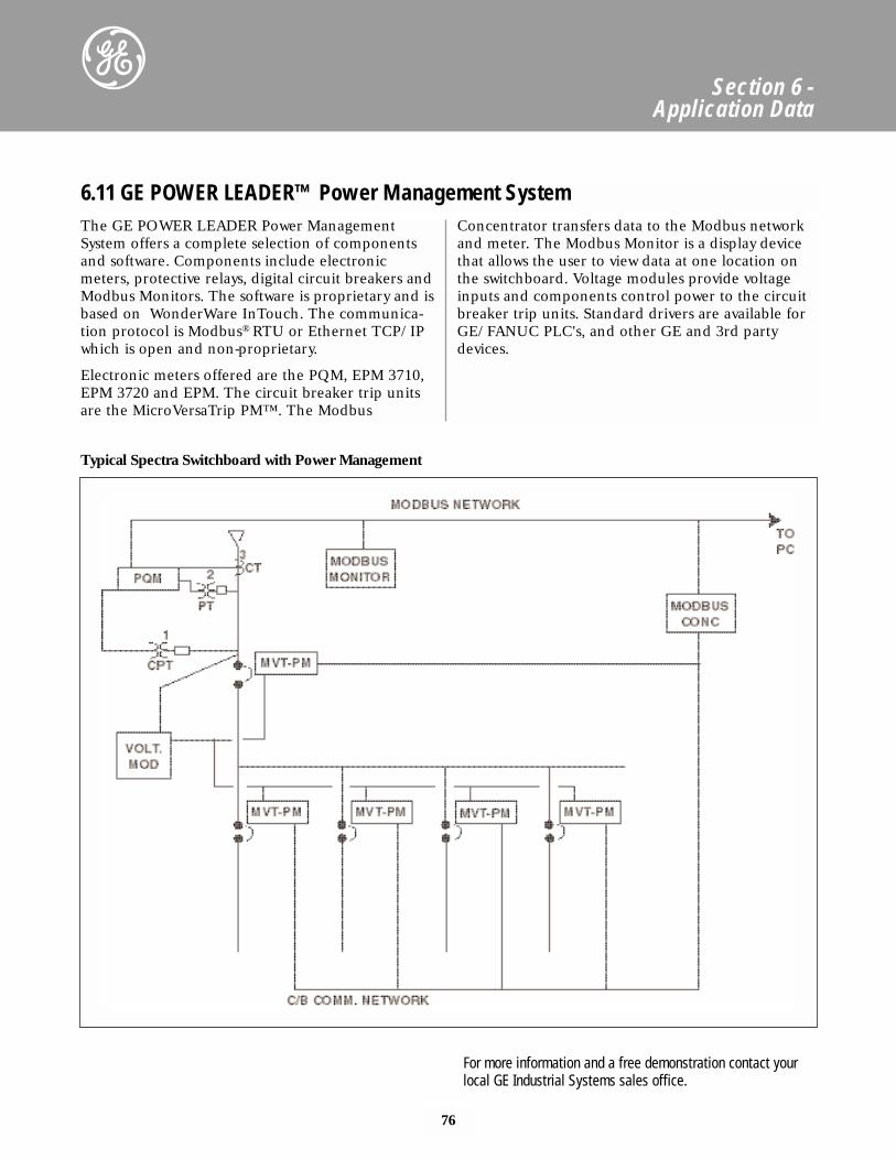
76
Section 6 - Application Data
The GE POWER LEADER Power ManagementSystem offers a complete selection of componentsand software. Components include electronicmeters, protective relays, digital circuit breakers andModbus Monitors. The software is proprietary and isbased on WonderWare InTouch. The communica-tion protocol is Modbus® RTU or Ethernet TCP/IPwhich is open and non-proprietary.
Electronic meters offered are the PQM, EPM 3710,EPM 3720 and EPM. The circuit breaker trip unitsare the MicroVersaTrip PM™. The Modbus
Concentrator transfers data to the Modbus networkand meter. The Modbus Monitor is a display devicethat allows the user to view data at one location onthe switchboard. Voltage modules provide voltageinputs and components control power to the circuitbreaker trip units. Standard drivers are available forGE/FANUC PLC's, and other GE and 3rd partydevices.
6.11 GE POWER LEADER™ Power Management System
For more information and a free demonstration contact yourlocal GE Industrial Systems sales office.
Typical Spectra Switchboard with Power Management
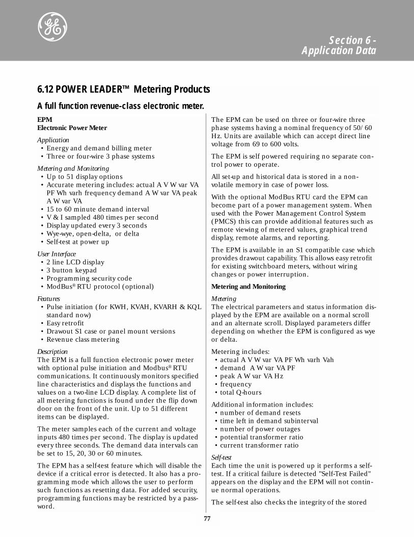
77
Section 6 - Application Data
EPMElectronic Power Meter
Application• Energy and demand billing meter• Three or four-wire 3 phase systems
Metering and Monitoring• Up to 51 display options• Accurate metering includes: actual A V W var VA
PF Wh varh frequency demand A W var VA peakA W var VA
• 15 to 60 minute demand interval• V & I sampled 480 times per second• Display updated every 3 seconds• Wye-wye, open-delta, or delta • Self-test at power up
User Interface• 2 line LCD display• 3 button keypad• Programming security code• ModBus® RTU protocol (optional)
Features• Pulse initiation (for KWH, KVAH, KVARH & KQL
standard now)• Easy retrofit• Drawout S1 case or panel mount versions• Revenue class metering
DescriptionThe EPM is a full function electronic power meterwith optional pulse initiation and Modbus® RTUcommunications. It continuously monitors specifiedline characteristics and displays the functions andvalues on a two-line LCD display. A complete list ofall metering functions is found under the flip downdoor on the front of the unit. Up to 51 differentitems can be displayed.
The meter samples each of the current and voltageinputs 480 times per second. The display is updatedevery three seconds. The demand data intervals canbe set to 15, 20, 30 or 60 minutes.
The EPM has a self-test feature which will disable thedevice if a critical error is detected. It also has a pro-gramming mode which allows the user to performsuch functions as resetting data. For added security,programming functions may be restricted by a pass-word.
The EPM can be used on three or four-wire threephase systems having a nominal frequency of 50/60Hz. Units are available which can accept direct linevoltage from 69 to 600 volts.
The EPM is self powered requiring no separate con-trol power to operate.
All set-up and historical data is stored in a non-volatile memory in case of power loss.
With the optional ModBus RTU card the EPM canbecome part of a power management system. Whenused with the Power Management Control System(PMCS) this can provide additional features such asremote viewing of metered values, graphical trenddisplay, remote alarms, and reporting.
The EPM is available in an S1 compatible case whichprovides drawout capability. This allows easy retrofitfor existing switchboard meters, without wiringchanges or power interruption.
Metering and Monitoring
MeteringThe electrical parameters and status information dis-played by the EPM are available on a normal scrolland an alternate scroll. Displayed parameters differdepending on whether the EPM is configured as wyeor delta.
Metering includes:• actual A V W var VA PF Wh varh Vah• demand A W var VA PF• peak A W var VA Hz• frequency• total Q-hours
Additional information includes:• number of demand resets• time left in demand subinterval• number of power outages• potential transformer ratio• current transformer ratio
Self-testEach time the unit is powered up it performs a self-test. If a critical failure is detected "Self-Test Failed"appears on the display and the EPM will not contin-ue normal operations.
The self-test also checks the integrity of the stored
6.12 POWER LEADER™ Metering Products
A full function revenue-class electronic meter.
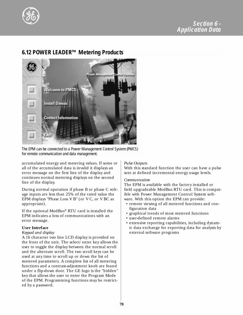
78
Section 6 - Application Data
accumulated energy and metering values. If some orall of the accumulated data is invalid it displays anerror message on the first line of the display andcontinues normal metering displays on the secondline of the display.
During normal operation if phase B or phase C volt-age inputs are less than 25% of the rated value theEPM displays "Phase Loss V B" (or V C, or V BC asappropriate).
If the optional ModBus® RTU card is installed theEPM indicates a loss of communications with anerror message.
User InterfaceKeypad and displayA 16 character two line LCD display is provided onthe front of the unit. The select/enter key allows theuser to toggle the display between the normal scrolland the alternate scroll. The two scroll keys can beused at any time to scroll up or down the list ofmetered parameters. A complete list of all meteringfunctions and a contrast-adjustment knob are foundunder a flip-down door. The GE logo is the "hidden"key that allows the user to enter the Program Modeof the EPM. Programming functions may be restrict-ed by a password.
Pulse OutputsWith this standard function the user can have a pulsesent at defined incremental energy usage levels.
CommunicationThe EPM is available with the factory installed orfield upgradeable ModBus RTU card. This is compat-ible with Power Management Control System soft-ware. With this option the EPM can provide:• remote viewing of all metered functions and con-
figuration data• graphical trends of most metered functions• user-defined remote alarms• extensive reporting capabilities, including dynam-
ic data exchange for exporting data for analysis byexternal software programs
6.12 POWER LEADER™ Metering Products
The EPM can be connected to a Power Management Control System (PMCS)for remote communication and data management.
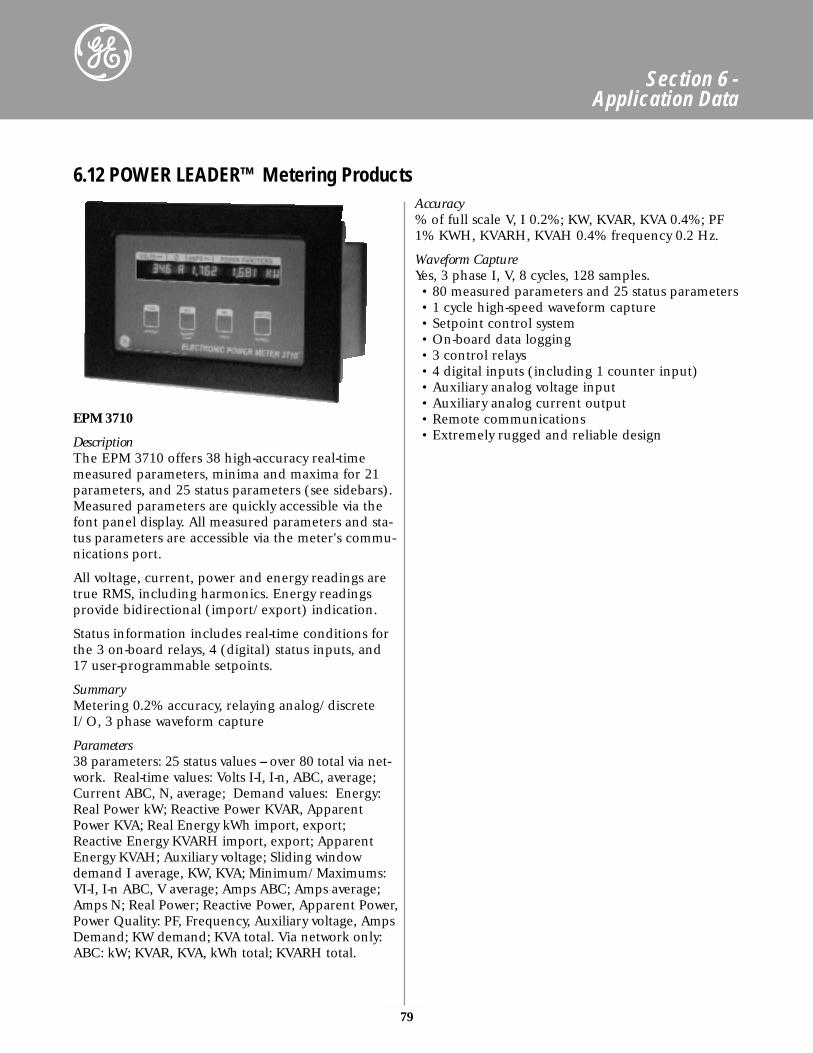
79
Section 6 - Application Data
6.12 POWER LEADER™ Metering Products
EPM 3710
DescriptionThe EPM 3710 offers 38 high-accuracy real-timemeasured parameters, minima and maxima for 21parameters, and 25 status parameters (see sidebars).Measured parameters are quickly accessible via thefont panel display. All measured parameters and sta-tus parameters are accessible via the meter's commu-nications port.
All voltage, current, power and energy readings aretrue RMS, including harmonics. Energy readingsprovide bidirectional (import/export) indication.
Status information includes real-time conditions forthe 3 on-board relays, 4 (digital) status inputs, and17 user-programmable setpoints.
SummaryMetering 0.2% accuracy, relaying analog/discreteI/O, 3 phase waveform capture
Parameters38 parameters: 25 status values -- over 80 total via net-work. Real-time values: Volts I-I, I-n, ABC, average;Current ABC, N, average; Demand values: Energy:Real Power kW; Reactive Power KVAR, ApparentPower KVA; Real Energy kWh import, export;Reactive Energy KVARH import, export; ApparentEnergy KVAH; Auxiliary voltage; Sliding windowdemand I average, KW, KVA; Minimum/Maximums:VI-I, I-n ABC, V average; Amps ABC; Amps average;Amps N; Real Power; Reactive Power, Apparent Power,Power Quality: PF, Frequency, Auxiliary voltage, AmpsDemand; KW demand; KVA total. Via network only:ABC: kW; KVAR, KVA, kWh total; KVARH total.
Accuracy% of full scale V, I 0.2%; KW, KVAR, KVA 0.4%; PF1% KWH, KVARH, KVAH 0.4% frequency 0.2 Hz.
Waveform CaptureYes, 3 phase I, V, 8 cycles, 128 samples.• 80 measured parameters and 25 status parameters• 1 cycle high-speed waveform capture• Setpoint control system• On-board data logging• 3 control relays• 4 digital inputs (including 1 counter input)• Auxiliary analog voltage input• Auxiliary analog current output• Remote communications• Extremely rugged and reliable design
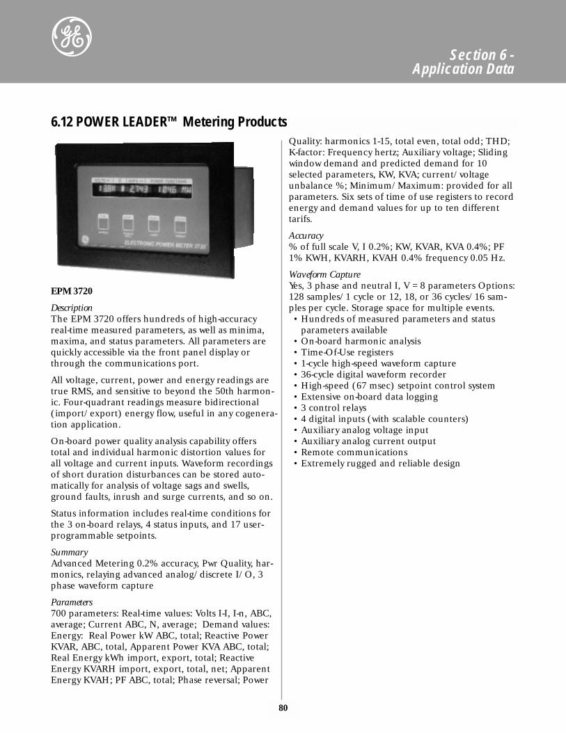
80
Section 6 - Application Data
6.12 POWER LEADER™ Metering Products
EPM 3720
DescriptionThe EPM 3720 offers hundreds of high-accuracyreal-time measured parameters, as well as minima,maxima, and status parameters. All parameters arequickly accessible via the front panel display orthrough the communications port.
All voltage, current, power and energy readings aretrue RMS, and sensitive to beyond the 50th harmon-ic. Four-quadrant readings measure bidirectional(import/export) energy flow, useful in any cogenera-tion application.
On-board power quality analysis capability offerstotal and individual harmonic distortion values forall voltage and current inputs. Waveform recordingsof short duration disturbances can be stored auto-matically for analysis of voltage sags and swells,ground faults, inrush and surge currents, and so on.
Status information includes real-time conditions forthe 3 on-board relays, 4 status inputs, and 17 user-programmable setpoints.
Summary Advanced Metering 0.2% accuracy, Pwr Quality, har-monics, relaying advanced analog/discrete I/O, 3phase waveform capture
Parameters 700 parameters: Real-time values: Volts I-I, I-n, ABC,average; Current ABC, N, average; Demand values:Energy: Real Power kW ABC, total; Reactive PowerKVAR, ABC, total, Apparent Power KVA ABC, total;Real Energy kWh import, export, total; ReactiveEnergy KVARH import, export, total, net; ApparentEnergy KVAH; PF ABC, total; Phase reversal; Power
Quality: harmonics 1-15, total even, total odd; THD;K-factor: Frequency hertz; Auxiliary voltage; Slidingwindow demand and predicted demand for 10selected parameters, KW, KVA; current/voltageunbalance %; Minimum/Maximum: provided for allparameters. Six sets of time of use registers to recordenergy and demand values for up to ten differenttarifs.
Accuracy% of full scale V, I 0.2%; KW, KVAR, KVA 0.4%; PF1% KWH, KVARH, KVAH 0.4% frequency 0.05 Hz.
Waveform Capture Yes, 3 phase and neutral I, V = 8 parameters Options:128 samples/1 cycle or 12, 18, or 36 cycles/16 sam-ples per cycle. Storage space for multiple events.• Hundreds of measured parameters and status
parameters available• On-board harmonic analysis• Time-Of-Use registers• 1-cycle high-speed waveform capture• 36-cycle digital waveform recorder• High-speed (67 msec) setpoint control system• Extensive on-board data logging• 3 control relays• 4 digital inputs (with scalable counters)• Auxiliary analog voltage input• Auxiliary analog current output• Remote communications• Extremely rugged and reliable design
81
Section 6 - Application Data
PQM T20CA Power Quality Meter
Applications• Metering of distribution feeders, transformers,
generators, capacitor banks and motors • Medium and low voltage systems• Commercial, industrial utility• Flexible control for demand load shedding,
power factor, etc.• Power quality analysis
Metering/Control• A V W var VA varh WH PF Hz unbalance• A W var VA demand• Load shedding• Power factor control• Output • Pulse output based on Kwh, kvarh or kVAh
Monitoring• Harmonic analysis through 63rd with THD and
TIF• Event recorder• Waveform capture• Data logger• Triggered trace memory
Communication• Ports: RS232 front, dual RS485 rear• ModBus® RTU protocol• Digital 4 in / 4 out• Analog 1 in / 4 out• Local/remote display of all value• Min SCADA software
DescriptionThe PQM is an ideal choice when continuous moni-toring of a three phase system is required. It providesmetering for current, voltage, real and reactivepower, energy use, cost of power, power factor andfrequency. Programmable setpoints and 4 assignableoutput relays allow control functions to be added forspecific applications. This includes basic alarm onover/under current or voltage, unbalance, demandbased load shedding, and capacitor power factor cor-rection control. More complex control is possibleusing the 4 switch inputs which also can be used forstatus such as breaker open/closed, flow informationetc.
The PQM may be used as a data gathering device fora plant automation system that integrates process,instrument and electrical requirements. All moni-tored values are available via two digital RS485 com-munication ports running the ModBus® protocol. Ifanalog values are required for direct interface to aPLC, any of the monitored values can be output toone of 4 isolated analog outputs. A process variablecan be measured using an analog input. A frontpanel RS232 communication port can be connectedto a PC for simultaneous access of information byother plant personnel.
The quality of the power system is important withincreasing use of electronic loads such as computer,ballasts or variable frequency drives. With the PQM'spower analysis option, any phase current or voltagecan be displayed and the harmonic content calculat-ed. By knowing the harmonic distribution, actioncan be taken to prevent overheated transformers,motors, capacitors, neutral wires and nuisance break-er trips. Redistribution of system loading can also bedetermined. Waveform and chart recorder printoutsavailable from the PQM assist in problem diagnosis.
Economical system monitoring or control is possibleby selecting the non-display chassis model as a systemcomponent and adding required options to obtainthe desired level of functionality.
An easy to use windows based software package isavailable. This software can be used for meter set-upprogramming, can be used with a portable PC con-nected to the front-mounted RS-232 port for datagathering or waveform capture. It also can be uti-lized through the rear-mounted RS-485 port forremote monitoring of a single meter.
6.12 POWER LEADER™ Metering Products
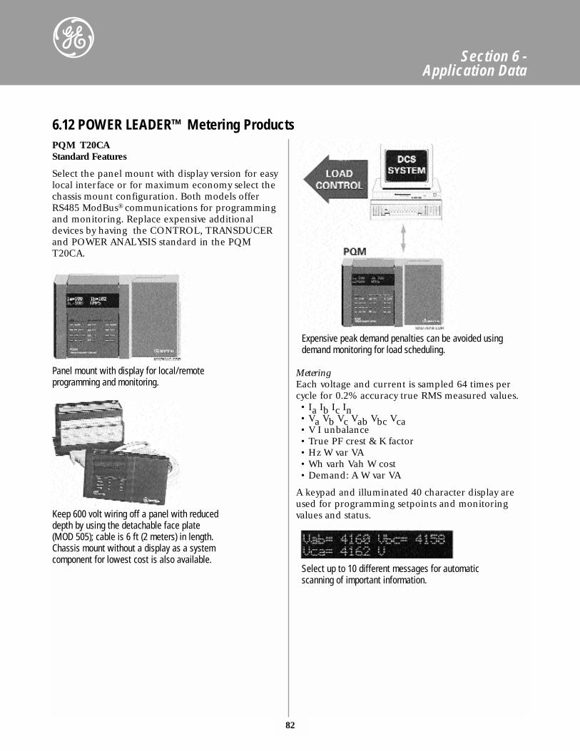
82
Section 6 - Application Data
PQM T20CA Standard Features
Select the panel mount with display version for easylocal interface or for maximum economy select thechassis mount configuration. Both models offerRS485 ModBus® communications for programmingand monitoring. Replace expensive additionaldevices by having the CONTROL, TRANSDUCERand POWER ANALYSIS standard in the PQMT20CA.
MeteringEach voltage and current is sampled 64 times percycle for 0.2% accuracy true RMS measured values.• Ia Ib Ic In• Va Vb Vc Vab Vbc Vca• V I unbalance• True PF crest & K factor• Hz W var VA• Wh varh Vah W cost• Demand: A W var VA
A keypad and illuminated 40 character display areused for programming setpoints and monitoring values and status.
6.12 POWER LEADER™ Metering Products
Panel mount with display for local/remoteprogramming and monitoring.
Expensive peak demand penalties can be avoided usingdemand monitoring for load scheduling.
Select up to 10 different messages for automaticscanning of important information.
Keep 600 volt wiring off a panel with reduceddepth by using the detachable face plate(MOD 505); cable is 6 ft (2 meters) in length.Chassis mount without a display as a systemcomponent for lowest cost is also available.
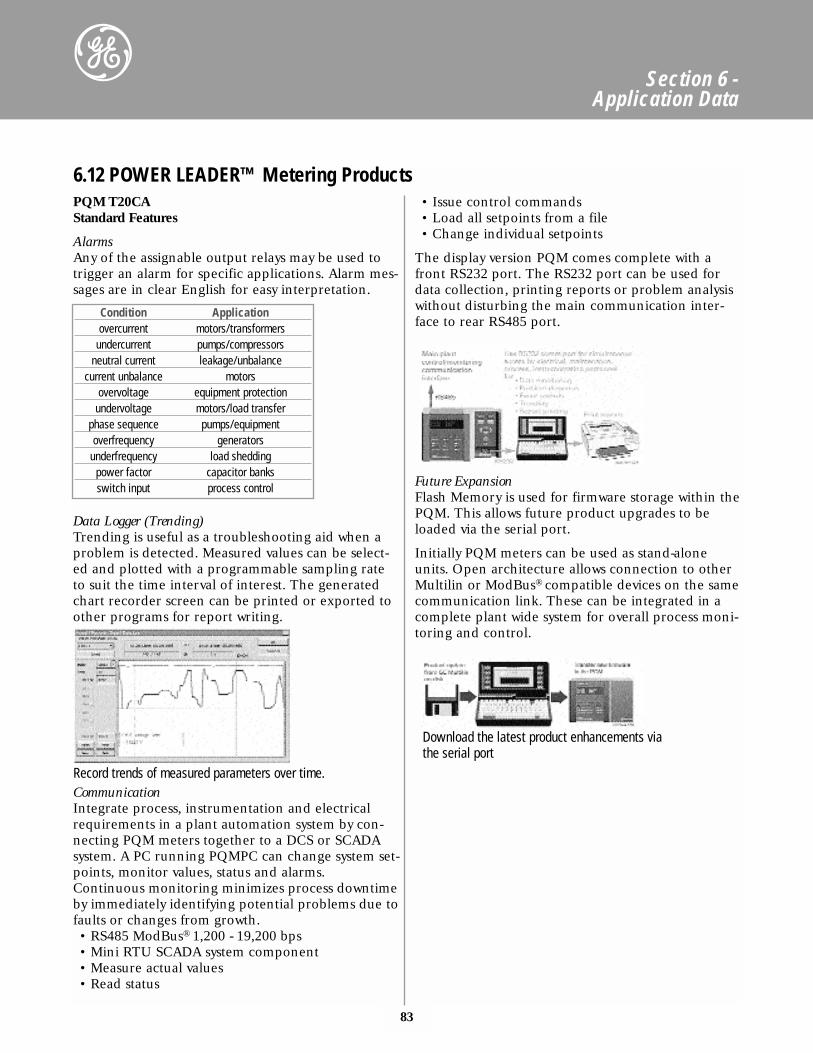
83
Section 6 - Application Data
PQM T20CA Standard Features
AlarmsAny of the assignable output relays may be used totrigger an alarm for specific applications. Alarm mes-sages are in clear English for easy interpretation.
Data Logger (Trending)Trending is useful as a troubleshooting aid when aproblem is detected. Measured values can be select-ed and plotted with a programmable sampling rateto suit the time interval of interest. The generatedchart recorder screen can be printed or exported toother programs for report writing.
CommunicationIntegrate process, instrumentation and electricalrequirements in a plant automation system by con-necting PQM meters together to a DCS or SCADAsystem. A PC running PQMPC can change system set-points, monitor values, status and alarms.Continuous monitoring minimizes process downtimeby immediately identifying potential problems due tofaults or changes from growth.• RS485 ModBus® 1,200 - 19,200 bps• Mini RTU SCADA system component• Measure actual values• Read status
• Issue control commands• Load all setpoints from a file• Change individual setpoints
The display version PQM comes complete with afront RS232 port. The RS232 port can be used fordata collection, printing reports or problem analysiswithout disturbing the main communication inter-face to rear RS485 port.
Future ExpansionFlash Memory is used for firmware storage within thePQM. This allows future product upgrades to beloaded via the serial port.
Initially PQM meters can be used as stand-aloneunits. Open architecture allows connection to otherMultilin or ModBus® compatible devices on the samecommunication link. These can be integrated in acomplete plant wide system for overall process moni-toring and control.
6.12 POWER LEADER™ Metering Products
Record trends of measured parameters over time.
Download the latest product enhancements viathe serial port
Condition Applicationovercurrent motors/transformers
undercurrent pumps/compressorsneutral current leakage/unbalance
current unbalance motorsovervoltage equipment protection
undervoltage motors/load transferphase sequence pumps/equipmentoverfrequency generators
underfrequency load sheddingpower factor capacitor banksswitch input process control
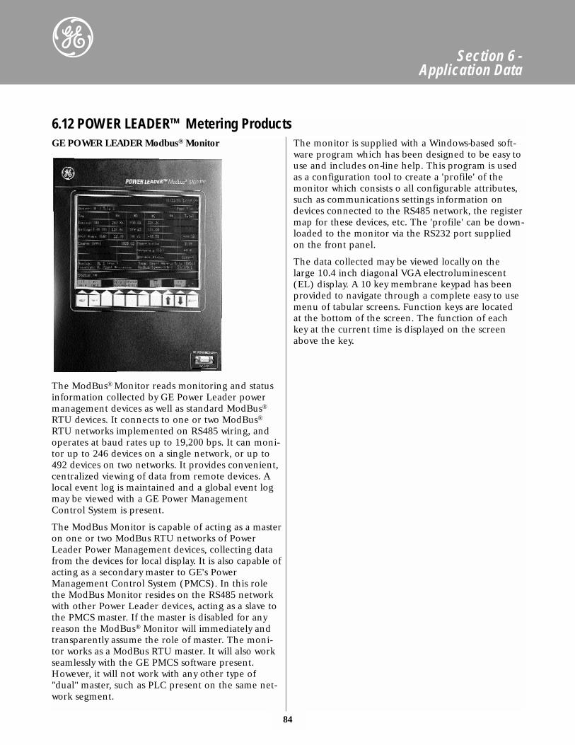
84
Section 6 - Application Data
GE POWER LEADER Modbus® Monitor
The ModBus® Monitor reads monitoring and statusinformation collected by GE Power Leader powermanagement devices as well as standard ModBus®
RTU devices. It connects to one or two ModBus®
RTU networks implemented on RS485 wiring, andoperates at baud rates up to 19,200 bps. It can moni-tor up to 246 devices on a single network, or up to492 devices on two networks. It provides convenient,centralized viewing of data from remote devices. Alocal event log is maintained and a global event logmay be viewed with a GE Power ManagementControl System is present.
The ModBus Monitor is capable of acting as a masteron one or two ModBus RTU networks of PowerLeader Power Management devices, collecting datafrom the devices for local display. It is also capable ofacting as a secondary master to GE's PowerManagement Control System (PMCS). In this rolethe ModBus Monitor resides on the RS485 networkwith other Power Leader devices, acting as a slave tothe PMCS master. If the master is disabled for anyreason the ModBus® Monitor will immediately andtransparently assume the role of master. The moni-tor works as a ModBus RTU master. It will also workseamlessly with the GE PMCS software present.However, it will not work with any other type of"dual" master, such as PLC present on the same net-work segment.
The monitor is supplied with a Windows-based soft-ware program which has been designed to be easy touse and includes on-line help. This program is usedas a configuration tool to create a 'profile' of themonitor which consists o all configurable attributes,such as communications settings information ondevices connected to the RS485 network, the registermap for these devices, etc. The 'profile' can be down-loaded to the monitor via the RS232 port suppliedon the front panel.
The data collected may be viewed locally on thelarge 10.4 inch diagonal VGA electroluminescent(EL) display. A 10 key membrane keypad has beenprovided to navigate through a complete easy to usemenu of tabular screens. Function keys are locatedat the bottom of the screen. The function of eachkey at the current time is displayed on the screenabove the key.
6.12 POWER LEADER™ Metering Products
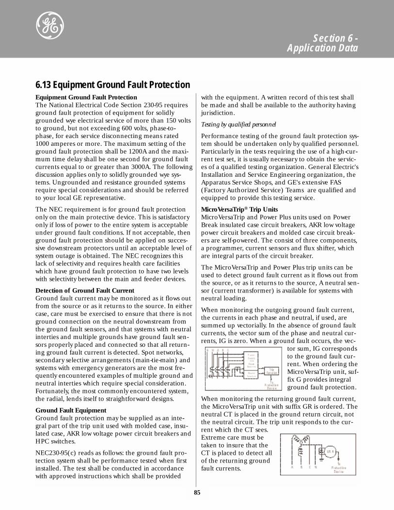
85
Section 6 - Application Data
Equipment Ground Fault ProtectionThe National Electrical Code Section 230-95 requiresground fault protection of equipment for solidlygrounded wye electrical service of more than 150 voltsto ground, but not exceeding 600 volts, phase-to-phase, for each service disconnecting means rated1000 amperes or more. The maximum setting of theground fault protection shall be 1200A and the maxi-mum time delay shall be one second for ground faultcurrents equal to or greater than 3000A. The followingdiscussion applies only to solidly grounded wye sys-tems. Ungrounded and resistance grounded systemsrequire special considerations and should be referredto your local GE representative.
The NEC requirement is for ground fault protectiononly on the main protective device. This is satisfactoryonly if loss of power to the entire system is acceptableunder ground fault conditions. If not acceptable, thenground fault protection should be applied on succes-sive downstream protectors until an acceptable level ofsystem outage is obtained. The NEC recognizes thislack of selectivity and requires health care facilitieswhich have ground fault protection to have two levelswith selectivity between the main and feeder devices.
Detection of Ground Fault CurrentGround fault current may be monitored as it flows outfrom the source or as it returns to the source. In eithercase, care must be exercised to ensure that there is notground connection on the neutral downstream fromthe ground fault sensors, and that systems with neutralinterties and multiple grounds have ground fault sen-sors properly placed and connected so that all return-ing ground fault current is detected. Spot networks,secondary selective arrangements (main-tie-main) andsystems with emergency generators are the most fre-quently encountered examples of multiple ground andneutral interties which require special consideration.Fortunately, the most commonly encountered system,the radial, lends itself to straightforward designs.
Ground Fault EquipmentGround fault protection may be supplied as an inte-gral part of the trip unit used with molded case, insu-lated case, AKR low voltage power circuit breakers andHPC switches.
NEC230-95(c) reads as follows: the ground fault pro-tection system shall be performance tested when firstinstalled. The test shall be conducted in accordancewith approved instructions which shall be provided
with the equipment. A written record of this test shallbe made and shall be available to the authority havingjurisdiction.
Testing by qualified personnel
Performance testing of the ground fault protection sys-tem should be undertaken only by qualified personnel.Particularly in the tests requiring the use of a high-cur-rent test set, it is usually necessary to obtain the servic-es of a qualified testing organization. General Electric'sInstallation and Service Engineering organization, theApparatus Service Shops, and GE's extensive FAS(Factory Authorized Service) Teams are qualified andequipped to provide this testing service.
MicroVersaTrip® Trip UnitsMicroVersaTrip and Power Plus units used on PowerBreak insulated case circuit breakers, AKR low voltagepower circuit breakers and molded case circuit break-ers are self-powered. The consist of three components,a programmer, current sensors and flux shifter, whichare integral parts of the circuit breaker.
The MicroVersaTrip and Power Plus trip units can beused to detect ground fault current as it flows out fromthe source, or as it returns to the source, A neutral sen-sor (current transformer) is available for systems withneutral loading.
When monitoring the outgoing ground fault current,the currents in each phase and neutral, if used, aresummed up vectorially. In the absence of ground faultcurrents, the vector sum of the phase and neutral cur-rents, IG is zero. When a ground fault occurs, the vec-
tor sum, IG correspondsto the ground fault cur-rent. When ordering theMicroVersaTrip unit, suf-fix G provides integralground fault protection.
When monitoring the returning ground fault current,the MicroVersaTrip unit with suffix GR is ordered. Theneutral CT is placed in the ground return circuit, notthe neutral circuit. The trip unit responds to the cur-rent which the CT sees.Extreme care must betaken to insure that theCT is placed to detect allof the returning groundfault currents.
6.13 Equipment Ground Fault Protection
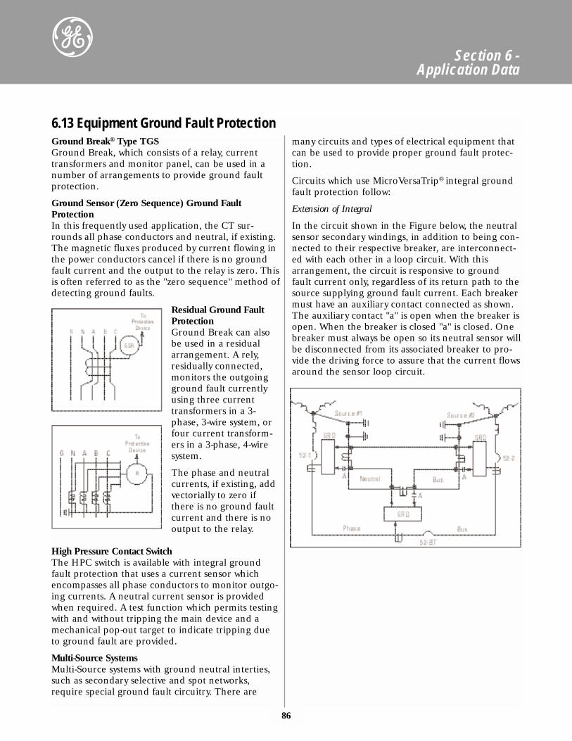
86
Section 6 - Application Data
Ground Break® Type TGSGround Break, which consists of a relay, currenttransformers and monitor panel, can be used in anumber of arrangements to provide ground faultprotection.
Ground Sensor (Zero Sequence) Ground FaultProtectionIn this frequently used application, the CT sur-rounds all phase conductors and neutral, if existing.The magnetic fluxes produced by current flowing inthe power conductors cancel if there is no groundfault current and the output to the relay is zero. Thisis often referred to as the "zero sequence" method ofdetecting ground faults.
Residual Ground FaultProtectionGround Break can alsobe used in a residualarrangement. A rely,residually connected,monitors the outgoingground fault currentlyusing three currenttransformers in a 3-phase, 3-wire system, orfour current transform-ers in a 3-phase, 4-wiresystem.
The phase and neutralcurrents, if existing, addvectorially to zero ifthere is no ground faultcurrent and there is nooutput to the relay.
High Pressure Contact SwitchThe HPC switch is available with integral groundfault protection that uses a current sensor whichencompasses all phase conductors to monitor outgo-ing currents. A neutral current sensor is providedwhen required. A test function which permits testingwith and without tripping the main device and amechanical pop-out target to indicate tripping dueto ground fault are provided.
Multi-Source SystemsMulti-Source systems with ground neutral interties,such as secondary selective and spot networks,require special ground fault circuitry. There are
many circuits and types of electrical equipment thatcan be used to provide proper ground fault protec-tion.
Circuits which use MicroVersaTrip® integral groundfault protection follow:
Extension of Integral
In the circuit shown in the Figure below, the neutralsensor secondary windings, in addition to being con-nected to their respective breaker, are interconnect-ed with each other in a loop circuit. With thisarrangement, the circuit is responsive to groundfault current only, regardless of its return path to thesource supplying ground fault current. Each breakermust have an auxiliary contact connected as shown.The auxiliary contact "a" is open when the breaker isopen. When the breaker is closed "a" is closed. Onebreaker must always be open so its neutral sensor willbe disconnected from its associated breaker to pro-vide the driving force to assure that the current flowsaround the sensor loop circuit.
6.13 Equipment Ground Fault Protection
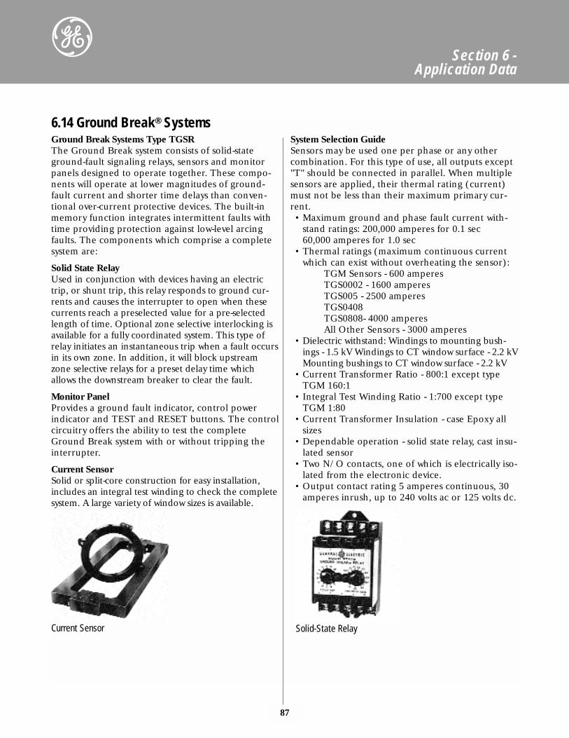
87
Section 6 - Application Data
Ground Break Systems Type TGSRThe Ground Break system consists of solid-stateground-fault signaling relays, sensors and monitorpanels designed to operate together. These compo-nents will operate at lower magnitudes of ground-fault current and shorter time delays than conven-tional over-current protective devices. The built-inmemory function integrates intermittent faults withtime providing protection against low-level arcingfaults. The components which comprise a completesystem are:
Solid State RelayUsed in conjunction with devices having an electrictrip, or shunt trip, this relay responds to ground cur-rents and causes the interrupter to open when thesecurrents reach a preselected value for a pre-selectedlength of time. Optional zone selective interlocking isavailable for a fully coordinated system. This type ofrelay initiates an instantaneous trip when a fault occursin its own zone. In addition, it will block upstreamzone selective relays for a preset delay time whichallows the downstream breaker to clear the fault.
Monitor PanelProvides a ground fault indicator, control powerindicator and TEST and RESET buttons. The controlcircuitry offers the ability to test the completeGround Break system with or without tripping theinterrupter.
Current SensorSolid or split-core construction for easy installation,includes an integral test winding to check the completesystem. A large variety of window sizes is available.
System Selection GuideSensors may be used one per phase or any othercombination. For this type of use, all outputs except"T" should be connected in parallel. When multiplesensors are applied, their thermal rating (current)must not be less than their maximum primary cur-rent. • Maximum ground and phase fault current with-
stand ratings: 200,000 amperes for 0.1 sec60,000 amperes for 1.0 sec
• Thermal ratings (maximum continuous currentwhich can exist without overheating the sensor):
TGM Sensors - 600 amperesTGS0002 - 1600 amperesTGS005 - 2500 amperes TGS0408TGS0808- 4000 amperesAll Other Sensors - 3000 amperes
• Dielectric withstand: Windings to mounting bush-ings - 1.5 kV Windings to CT window surface - 2.2 kVMounting bushings to CT window surface - 2.2 kV
• Current Transformer Ratio - 800:1 except typeTGM 160:1
• Integral Test Winding Ratio - 1:700 except typeTGM 1:80
• Current Transformer Insulation - case Epoxy allsizes
• Dependable operation - solid state relay, cast insu-lated sensor
• Two N/O contacts, one of which is electrically iso-lated from the electronic device.
• Output contact rating 5 amperes continuous, 30amperes inrush, up to 240 volts ac or 125 volts dc.
6.14 Ground Break® Systems
Current Sensor Solid-State Relay
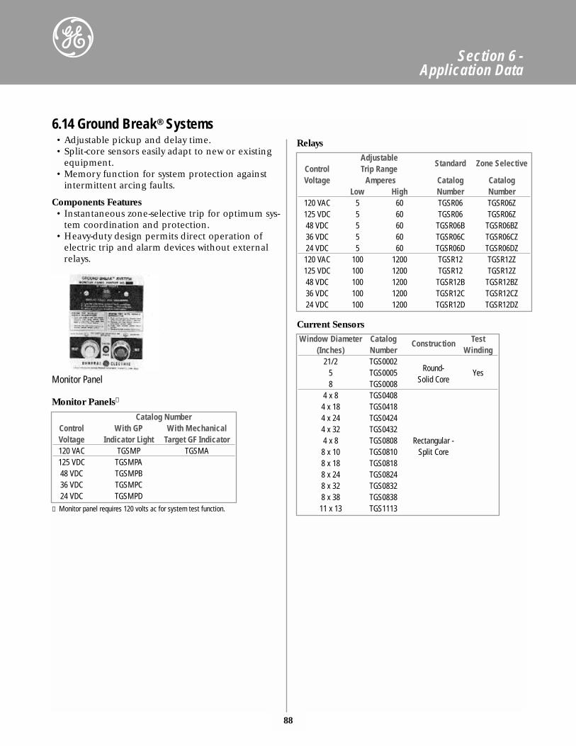
• Adjustable pickup and delay time.• Split-core sensors easily adapt to new or existing
equipment.• Memory function for system protection against
intermittent arcing faults.
Components Features• Instantaneous zone-selective trip for optimum sys-
tem coordination and protection.• Heavy-duty design permits direct operation of
electric trip and alarm devices without externalrelays.
88
Section 6 - Application Data
AdjustableStandard Zone Selective
Control Trip RangeVoltage Amperes Catalog Catalog
Low High Number Number120 VAC 5 60 TGSR06 TGSR06Z125 VDC 5 60 TGSR06 TGSR06Z48 VDC 5 60 TGSR06B TGSR06BZ36 VDC 5 60 TGSR06C TGSR06CZ24 VDC 5 60 TGSR06D TGSR06DZ120 VAC 100 1200 TGSR12 TGSR12Z125 VDC 100 1200 TGSR12 TGSR12Z48 VDC 100 1200 TGSR12B TGSR12BZ36 VDC 100 1200 TGSR12C TGSR12CZ24 VDC 100 1200 TGSR12D TGSR12DZ
Window Diameter Catalog Construction Test(Inches) Number Winding
21/2 TGS00025 TGS0005 Round- Yes8 TGS0008 Solid Core
4 x 8 TGS04084 x 18 TGS04184 x 24 TGS04244 x 32 TGS04324 x 8 TGS0808 Rectangular -8 x 10 TGS0810 Split Core8 x 18 TGS08188 x 24 TGS08248 x 32 TGS08328 x 38 TGS083811 x 13 TGS1113
Catalog NumberControl With GP With MechanicalVoltage Indicator Light Target GF Indicator120 VAC TGSMP TGSMA125 VDC TGSMPA48 VDC TGSMPB36 VDC TGSMPC24 VDC TGSMPD
① Monitor panel requires 120 volts ac for system test function.
6.14 Ground Break® SystemsRelays
Monitor Panels①
Current Sensors
Monitor Panel
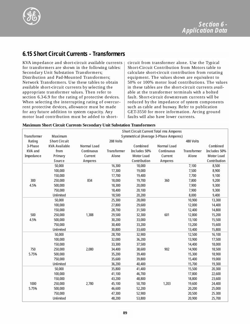
Maximum Short Circuit Currents Secondary Unit Substation Transformers
89
Section 6 - Application Data
KVA impedance and short-circuit available currentsfor transformers are shown in the following tables:Secondary Unit Substation Transformers;Distribution and Pad-Mounted Transformers;Network Transformers. Use these tables to obtainavailable short-circuit currents by selecting theappropriate transformer values. Then refer to section 6.3-6.9 for the rating of protective devices.When selecting the interrupting rating of overcur-rent protective devices, allowance must be madefor any future addition to system capacity. Anymotor load contribution must be added to short-
circuit from transformer alone. Use the TypicalShort-Circuit Contribution from Motors table tocalculate short-circuit contribution from rotatingequipment. The values shown are equivalent to50% or 100% motor load contributions. The valuesin these tables are the short-circuit currents avail-able at the transformer terminals with a boltedfault. Short-circuit downstream currents will bereduced by the impedance of system componentssuch as cable and busway. Refer to publicationGET-3550 for more information. Arcing groundfaults will also have lower currents.
Short Circuit Current Total rms AmperesTransformer Maximum Symmetrical (Average 3-Phase Amperes)
Rating Short Circuit 208 Volts 480 Volts3-Phase KVA Available Normal Load Combined Normal Load CombinedKVA and from Continuous Transformer Includes 50% Continuous Transformer Includes 50%
Impedance Primary Current Alone Motor Load Current Alone Motor LoadSource Amperes Contribution Amperes Contribution50,000 16,300 18,000 7,100 8,500100,000 17,300 19,000 7,500 8,900150,000 17,700 19,400 7,700 9,100
300 250,000 834 18,000 19,700 360 7,800 9,2004.5% 500,000 18,300 20,000 7,900 9,300
750,000 18,400 20,100 7,900 9,300Unlimited 18,500 20,200 8,000 9,400
50,000 25,300 28,000 10,900 13,300100,000 27,800 29,600 12,000 14,400150,000 28,700 31,500 12,400 14,800
500 250,000 1,388 29,500 32,300 601 12,800 15,2004.5% 500,000 30,200 33,000 13,100 15,500
750,000 30,400 33,200 13,200 15,600Unlimited 30,800 33,600 13,400 15,800
50,000 28,700 32,900 12,500 16,100100,000 32,000 36,200 13,900 17,500150,000 33,300 37,500 14,400 18,000
750 250,000 2,080 34,400 38,600 902 14,900 18,5005.75% 500,000 35,200 39,400 15,300 18,900
750,000 35,600 39,800 15,400 19,000Unlimited 36,200 40,400 15,700 19,300
50,000 35,800 41,400 15,500 20,300100,000 41,100 46,700 17,800 22,600150,000 43,200 48,800 18,800 23,600
1000 250,000 2,780 45,100 50,700 1,203 19,600 24,4005.75% 500,000 46,600 52,200 20,200 25,000
750,000 47,300 52,900 20,500 25.300Unlimited 48,200 53,800 20,900 25,700
6.15 Short Circuit Currents - Transformers
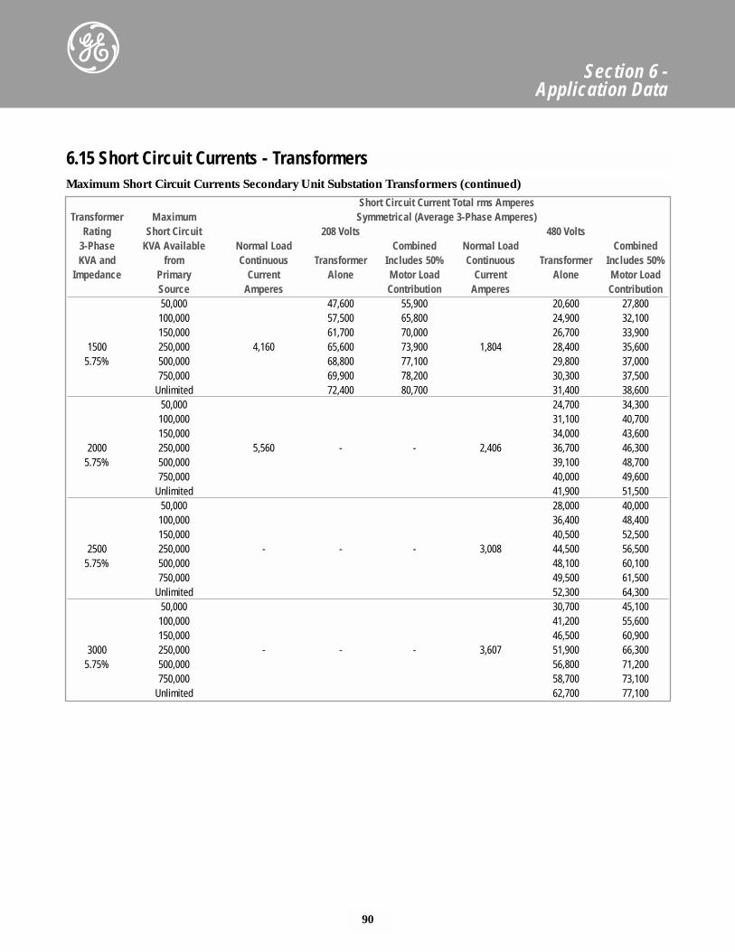
90
Section 6 - Application Data
Maximum Short Circuit Currents Secondary Unit Substation Transformers (continued)Short Circuit Current Total rms Amperes
Transformer Maximum Symmetrical (Average 3-Phase Amperes)Rating Short Circuit 208 Volts 480 Volts
3-Phase KVA Available Normal Load Combined Normal Load CombinedKVA and from Continuous Transformer Includes 50% Continuous Transformer Includes 50%
Impedance Primary Current Alone Motor Load Current Alone Motor LoadSource Amperes Contribution Amperes Contribution50,000 47,600 55,900 20,600 27,800100,000 57,500 65,800 24,900 32,100150,000 61,700 70,000 26,700 33,900
1500 250,000 4,160 65,600 73,900 1,804 28,400 35,6005.75% 500,000 68,800 77,100 29,800 37,000
750,000 69,900 78,200 30,300 37,500Unlimited 72,400 80,700 31,400 38,600
50,000 24,700 34,300100,000 31,100 40,700150,000 34,000 43,600
2000 250,000 5,560 - - 2,406 36,700 46,3005.75% 500,000 39,100 48,700
750,000 40,000 49,600Unlimited 41,900 51,500
50,000 28,000 40,000100,000 36,400 48,400150,000 40,500 52,500
2500 250,000 - - - 3,008 44,500 56,5005.75% 500,000 48,100 60,100
750,000 49,500 61,500Unlimited 52,300 64,300
50,000 30,700 45,100100,000 41,200 55,600150,000 46,500 60,900
3000 250,000 - - - 3,607 51,900 66,3005.75% 500,000 56,800 71,200
750,000 58,700 73,100Unlimited 62,700 77,100
6.15 Short Circuit Currents - Transformers
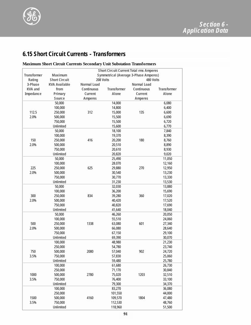
Maximum Short Circuit Currents Secondary Unit Substation Transformers
91
Section 6 - Application Data
Short Circuit Current Total rms AmperesTransformer Maximum Symmetrical (Average 3-Phase Amperes)
Rating Short Circuit 208 Volts 480 Volts3-Phase KVA Available Normal Load Normal LoadKVA and from Continuous Transformer Continuous Transformer
Impedance Primary Current Alone Current AloneSource Amperes Amperes50,000 14,000 6,080100,000 14,800 6,400
112.5 250,000 312 15,000 135 6,6002.0% 500,000 15,500 6,690
750,000 15,500 6,720Unlimited 15,600 6,770
50,000 18,100 7,840100,000 19,370 8,390
150 250,000 416 20,200 180 8,7602.0% 500,000 20,510 8,890
750,000 20,610 8,930Unlimited 20,820 9,020
50,000 25,490 11,050100,000 28.070 12,160
225 250,000 625 29,880 270 12,9502.0% 500,000 30,540 13,230
750,000 30,770 13,330Unlimited 31,230 13,530
50,000 32,030 13,880100,000 36,200 15,690
300 250,000 834 39,280 360 17,0202.0% 500,000 40,420 17,520
750,000 40,820 17,690Unlimited 41,640 18,040
50,000 46,260 20,050100,000 55,510 24,060
500 250,000 1338 63,080 601 27,3402.0% 500,000 66,080 28,640
750,000 67,150 29,100Unlimited 69,390 30,070100,000 48,980 21,230250,000 54,780 23,740
750 500,000 2080 57,040 902 24,7203.5% 750,000 57,830 25,060
Unlimited 59,480 25,780100,000 61,680 26,730250,000 71,170 30,840
1000 500,000 2780 75,020 1203 32,5103.5% 750,000 76,400 33,100
Unlimited 79,300 34,370100,000 83,270 36,080250,000 101,550 44,000
1500 500,000 4160 109,570 1804 47,4803.5% 750,000 112,530 48,760
Unlimited 118,960 51,500
6.15 Short Circuit Currents - Transformers
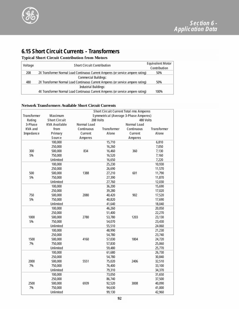
92
Section 6 - Application Data
Network Transformers Available Short Circuit Currents
Typical Short Circuit Contribution from Motors
Short Circuit Current Total rms AmperesTransformer Maximum Symmetrical (Average 3-Phase Amperes)
Rating Short Circuit 208 Volts 480 Volts3-Phase KVA Available Normal Load Normal LoadKVA and from Continuous Transformer Continuous Transformer
Impedance Primary Current Alone Current AloneSource Amperes Amperes100,000 15,710 6,810250,000 16,260 7,050
300 500,000 834 16,460 360 7,1305% 750,000 16,520 7,160
Unlimited 16,650 7,220100,000 25,230 10,930250,000 26,690 11,570
500 500,000 1388 27,210 601 11,7905% 750,000 27,390 11,870
Unlimited 27,760 12,030100,000 36,200 15,690250,000 39,280 17,020
750 500,000 2080 40,420 902 17,5205% 750,000 40,820 17,690
Unlimited 41,640 18,040100,000 46,260 20,050250,000 51,400 22,270
1000 500,000 2780 53,780 1203 23,1305% 750,000 54,070 23,430
Unlimited 55,510 24.060100,000 48,990 21,230250,000 54,780 23,740
1500 500,000 4160 57,030 1804 24,7207% 750,000 57,830 25,060
Unlimited 59,480 25,770100,000 61,680 26,730250,000 54,780 30,840
2000 500,000 5551 75,020 2406 32,5107% 750,000 76,400 33,100
Unlimited 79,310 34,370100,000 73,050 31,650250,000 86,740 37,500
2500 500,000 6939 92,520 3008 40,0907% 750,000 94,630 41,000
Unlimited 99,130 42,960
Voltage Short Circuit Contribution Equivalent Motor Contribution
208 2X Transformer Normal Load Continuous Current Amperes (or service ampere rating) 50%Commercial Buildings:
480 2X Transformer Normal Load Continuous Current Amperes (or service ampere rating) 50%Industrial Buildings:
4X Transformer Normal Load Continuous Current Amperes (or service ampere rating) 100%
6.15 Short Circuit Currents - Transformers
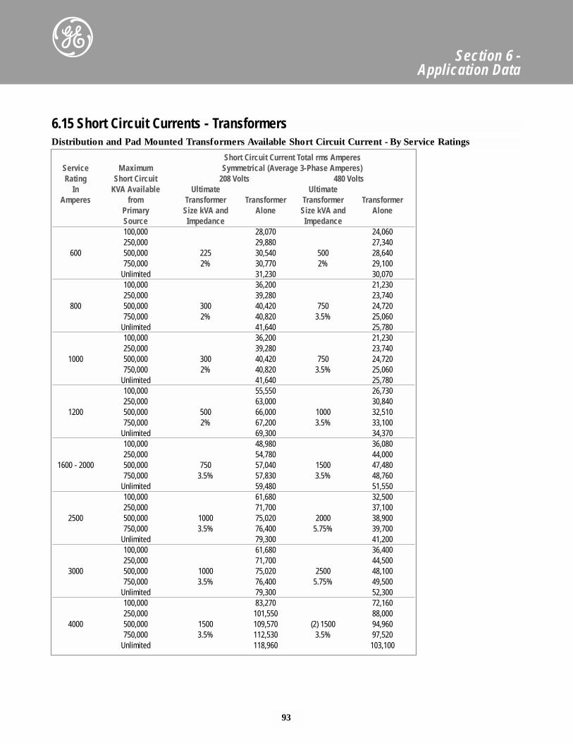
93
Section 6 - Application Data
Distribution and Pad Mounted Transformers Available Short Circuit Current - By Service Ratings
Short Circuit Current Total rms AmperesService Maximum Symmetrical (Average 3-Phase Amperes)Rating Short Circuit 208 Volts 480 Volts
In KVA Available Ultimate UltimateAmperes from Transformer Transformer Transformer Transformer
Primary Size kVA and Alone Size kVA and AloneSource Impedance Impedance100,000 28,070 24,060250,000 29,880 27,340
600 500,000 225 30,540 500 28,640750,000 2% 30,770 2% 29,100
Unlimited 31,230 30,070100,000 36,200 21,230250,000 39,280 23,740
800 500,000 300 40,420 750 24,720750,000 2% 40,820 3.5% 25,060
Unlimited 41,640 25,780100,000 36,200 21,230250,000 39,280 23,740
1000 500,000 300 40,420 750 24,720750,000 2% 40,820 3.5% 25,060
Unlimited 41,640 25,780100,000 55,550 26,730250,000 63,000 30,840
1200 500,000 500 66,000 1000 32,510750,000 2% 67,200 3.5% 33,100
Unlimited 69,300 34,370100,000 48,980 36,080250,000 54,780 44,000
1600 - 2000 500,000 750 57,040 1500 47,480750,000 3.5% 57,830 3.5% 48,760
Unlimited 59,480 51,550100,000 61,680 32,500250,000 71,700 37,100
2500 500,000 1000 75,020 2000 38,900750,000 3.5% 76,400 5.75% 39,700
Unlimited 79,300 41,200100,000 61,680 36,400250,000 71,700 44,500
3000 500,000 1000 75,020 2500 48,100750,000 3.5% 76,400 5.75% 49,500
Unlimited 79,300 52,300100,000 83,270 72,160250,000 101,550 88,000
4000 500,000 1500 109,570 (2) 1500 94,960750,000 3.5% 112,530 3.5% 97,520
Unlimited 118,960 103,100
6.15 Short Circuit Currents - Transformers
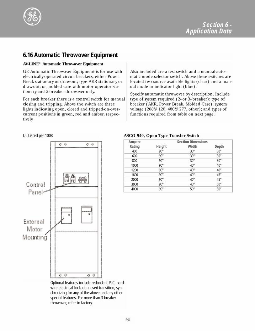
94
Section 6 - Application Data
AV-LINE® Automatic Throwover Equipment
GE Automatic Throwover Equipment is for use withelectrically-operated circuit breakers, either PowerBreak stationary or draw-out; type AKR stationary ordraw-out; or molded case with motor operator sta-tionary and 2-breaker throwover only.
For each breaker there is a control switch for manualclosing and tripping. Above the switch are threelights indicating open, closed and tripped-on-over-current positions in green, red and amber, respec-tively.
Also included are a test switch and a manual-auto-matic mode selector switch. Above these switches arelocated two source available lights (clear) and a man-ual mode in indicator light (blue).
Specify automatic throwover by description. Includetype of system required (2- or 3- breaker); type ofbreaker (AKR, Power Break, Molded Case); systemvoltage (208Y/120, 480Y/277, other); and types offunctions required from table on next page.
6.16 Automatic Throwover Equipment
Optional features include redundant PLC, hard-wire electrical lockout, closed transition, syn-chronizing for any of the above and any otherspecial features. For more than 3 breakerthrowover, refer to factory.
UL Listed per 1008Ampere Section DimensionsRating Height Width Depth
400 90” 30” 30”600 90” 30” 30”800 90” 30” 30”1000 90” 40” 40”1200 90” 40” 40”1600 90” 40” 45”2000 90” 40” 45”3000 90” 40” 50”4000 90” 50” 50”
ASCO 940, Open Type Transfer Switch
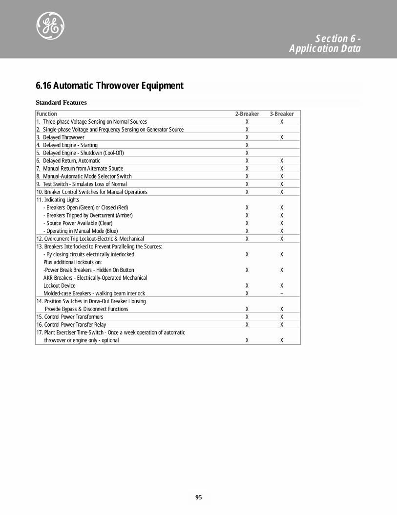
95
Section 6 - Application Data
6.16 Automatic Throwover Equipment
Function 2-Breaker 3-Breaker1. Three-phase Voltage Sensing on Normal Sources X X2. Single-phase Voltage and Frequency Sensing on Generator Source X3. Delayed Throwover X X4. Delayed Engine - Starting X5. Delayed Engine - Shutdown (Cool-Off) X6. Delayed Return, Automatic X X7. Manual Return from Alternate Source X X8. Manual-Automatic Mode Selector Switch X X9. Test Switch - Simulates Loss of Normal X X10. Breaker Control Switches for Manual Operations X X11. Indicating Lights
- Breakers Open (Green) or Closed (Red) X X- Breakers Tripped by Overcurrent (Amber) X X- Source Power Available (Clear) X X- Operating in Manual Mode (Blue) X X
12. Overcurrent Trip Lockout-Electric & Mechanical X X13. Breakers Interlocked to Prevent Paralleling the Sources:
- By closing circuits electrically interlocked X XPlus additional lockouts on:-Power Break Breakers - Hidden On Button X XAKR Breakers - Electrically-Operated MechanicalLockout Device X XMolded-case Breakers - walking beam interlock X –
14. Position Switches in Draw-Out Breaker HousingProvide Bypass & Disconnect Functions X X
15. Control Power Transformers X X16. Control Power Transfer Relay X X17. Plant Exerciser Time-Switch - Once a week operation of automatic
throwover or engine only - optional X X
Standard Features
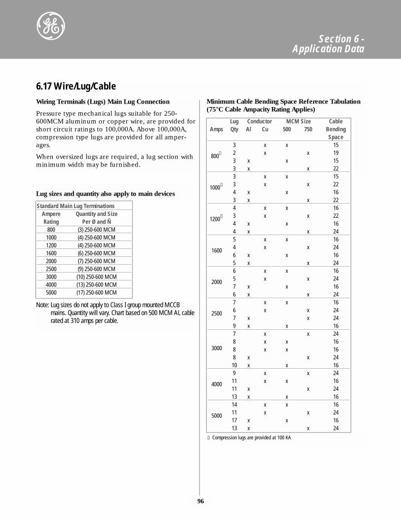
96
Section 6 - Application Data
Wiring Terminals (Lugs) Main Lug Connection
Pressure type mechanical lugs suitable for 250-600MCM aluminum or copper wire, are provided forshort circuit ratings to 100,000A. Above 100,000A,compression type lugs are provided for all amper-ages.
When oversized lugs are required, a lug section withminimum width may be furnished.
Standard Main Lug TerminationsAmpere Quantity and SizeRating Per Ø and Ñ
800 (3) 250-600 MCM1000 (4) 250-600 MCM1200 (4) 250-600 MCM1600 (6) 250-600 MCM2000 (7) 250-600 MCM2500 (9) 250-600 MCM3000 (10) 250-600 MCM4000 (13) 250-600 MCM5000 (17) 250-600 MCM
Lug Conductor MCM Size CableAmps Qty Al Cu 500 750 Bending
Space3 x x 15
800① 2 x x 193 x x 153 x x 223 x x 15
1000① 3 x x 224 x x 163 x x 224 x x 16
1200① 3 x x 224 x x 164 x x 245 x x 16
1600 4 x x 246 x x 165 x x 246 x x 16
2000 5 x x 247 x x 166 x x 247 x x 16
2500 6 x x 247 x x 249 x x 167 x x 24
30008 x x 168 x x 168 x x 2410 x x 169 x x 24
4000 11 x x 1611 x x 2413 x x 1614 x x 16
5000 11 x x 2417 x x 1613 x x 24
6.17 Wire/Lug/Cable
Lug sizes and quantity also apply to main devices
Minimum Cable Bending Space Reference Tabulation (75°C Cable Ampacity Rating Applies)
① Compression lugs are provided at 100 KA
Note: Lug sizes do not apply to Class I group mounted MCCBmains. Quantity will vary. Chart based on 500 MCM AL cablerated at 310 amps per cable.
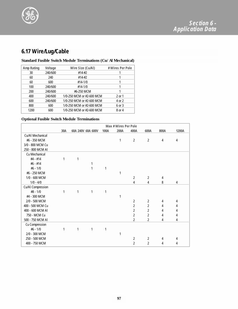
97
Section 6 - Application Data
Standard Fusible Switch Module Terminations (Cu/Al Mechanical)
Optional Fusible Switch Module Terminations
6.17 Wire/Lug/Cable
Amp Rating Voltage Wire Size (Cu/Al) # Wires Per Pole30 240/600 #14-#2 160 240 #14-#2 160 600 #14-1/0 1100 240/600 #14-1/0 1200 240/600 #6-250 MCM 1400 240/600 1/0-250 MCM or #2-600 MCM 2 or 1600 240/600 1/0-250 MCM or #2-600 MCM 4 or 2800 600 1/0-250 MCM or #2-600 MCM 6 or 31200 600 1/0-250 MCM or #2-600 MCM 8 or 4
Max # Wires Per Pole30A 60A 240V 60A 600V 100A 200A 400A 600A 800A 1200A
Cu/Al Mechanical#6 - 350 MCM 1 2 2 4 4
3/0 - 800 MCM Cu250 - 800 MCM Al
Cu Mechanical#4 - #14 1 1#6 - #14 1#6 - 1/0 1 1
#6 - 250 MCM 11/0 - 600 MCM 2 2 4
1/0 - 4/0 4 4 8 4Cu/Al Compression
#8 - 1/0 1 1 1 1#4 - 300 MCM 12/0 - 500 MCM 2 2 4 4
400 - 500 MCM Cu 2 2 4 4400 - 600 MCM Al 2 2 4 4
750 - MCM Cu 2 2 4 4500 - 750 MCM Al 2 2 4 4
Cu Compression#6 - 1/0 1 1 1 1
2/0 - 300 MCM 1250 - 500 MCM 2 2 4 4400 - 750 MCM 2 2 4 4
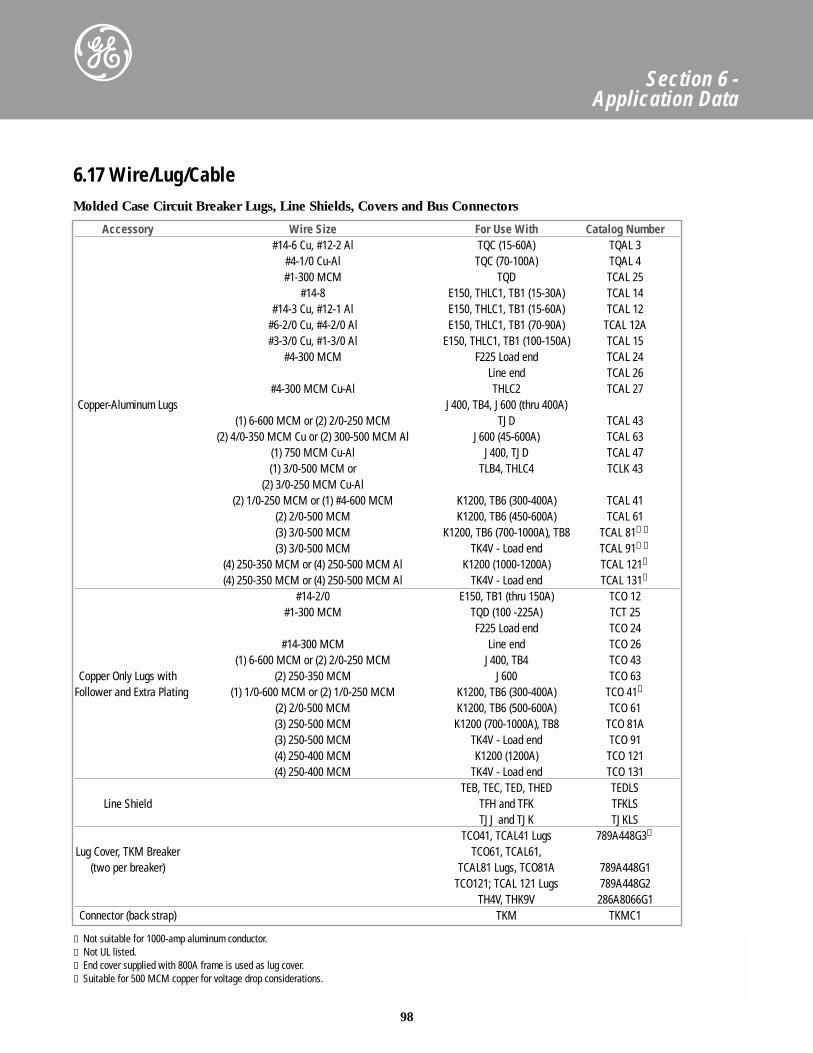
98
Section 6 - Application Data
Molded Case Circuit Breaker Lugs, Line Shields, Covers and Bus Connectors
6.17 Wire/Lug/Cable
Accessory Wire Size For Use With Catalog Number#14-6 Cu, #12-2 Al TQC (15-60A) TQAL 3
#4-1/0 Cu-Al TQC (70-100A) TQAL 4#1-300 MCM TQD TCAL 25
#14-8 E150, THLC1, TB1 (15-30A) TCAL 14#14-3 Cu, #12-1 Al E150, THLC1, TB1 (15-60A) TCAL 12
#6-2/0 Cu, #4-2/0 Al E150, THLC1, TB1 (70-90A) TCAL 12A#3-3/0 Cu, #1-3/0 Al E150, THLC1, TB1 (100-150A) TCAL 15
#4-300 MCM F225 Load end TCAL 24Line end TCAL 26
#4-300 MCM Cu-Al THLC2 TCAL 27Copper-Aluminum Lugs J400, TB4, J600 (thru 400A)
(1) 6-600 MCM or (2) 2/0-250 MCM TJD TCAL 43(2) 4/0-350 MCM Cu or (2) 300-500 MCM Al J600 (45-600A) TCAL 63
(1) 750 MCM Cu-Al J400, TJD TCAL 47(1) 3/0-500 MCM or TLB4, THLC4 TCLK 43
(2) 3/0-250 MCM Cu-Al(2) 1/0-250 MCM or (1) #4-600 MCM K1200, TB6 (300-400A) TCAL 41
(2) 2/0-500 MCM K1200, TB6 (450-600A) TCAL 61(3) 3/0-500 MCM K1200, TB6 (700-1000A), TB8 TCAL 81①➁
(3) 3/0-500 MCM TK4V - Load end TCAL 91①➁
(4) 250-350 MCM or (4) 250-500 MCM Al K1200 (1000-1200A) TCAL 121➃
(4) 250-350 MCM or (4) 250-500 MCM Al TK4V - Load end TCAL 131➃
#14-2/0 E150, TB1 (thru 150A) TCO 12#1-300 MCM TQD (100 -225A) TCT 25
F225 Load end TCO 24#14-300 MCM Line end TCO 26
(1) 6-600 MCM or (2) 2/0-250 MCM J400, TB4 TCO 43Copper Only Lugs with (2) 250-350 MCM J600 TCO 63
Follower and Extra Plating (1) 1/0-600 MCM or (2) 1/0-250 MCM K1200, TB6 (300-400A) TCO 41➁
(2) 2/0-500 MCM K1200, TB6 (500-600A) TCO 61(3) 250-500 MCM K1200 (700-1000A), TB8 TCO 81A(3) 250-500 MCM TK4V - Load end TCO 91(4) 250-400 MCM K1200 (1200A) TCO 121(4) 250-400 MCM TK4V - Load end TCO 131
TEB, TEC, TED, THED TEDLSLine Shield TFH and TFK TFKLS
TJJ and TJK TJKLSTCO41, TCAL41 Lugs 789A448G3➂
Lug Cover, TKM Breaker TCO61, TCAL61,(two per breaker) TCAL81 Lugs, TCO81A 789A448G1
TCO121; TCAL 121 Lugs 789A448G2TH4V, THK9V 286A8066G1
Connector (back strap) TKM TKMC1
① Not suitable for 1000-amp aluminum conductor.➁ Not UL listed.➂ End cover supplied with 800A frame is used as lug cover.➃ Suitable for 500 MCM copper for voltage drop considerations.
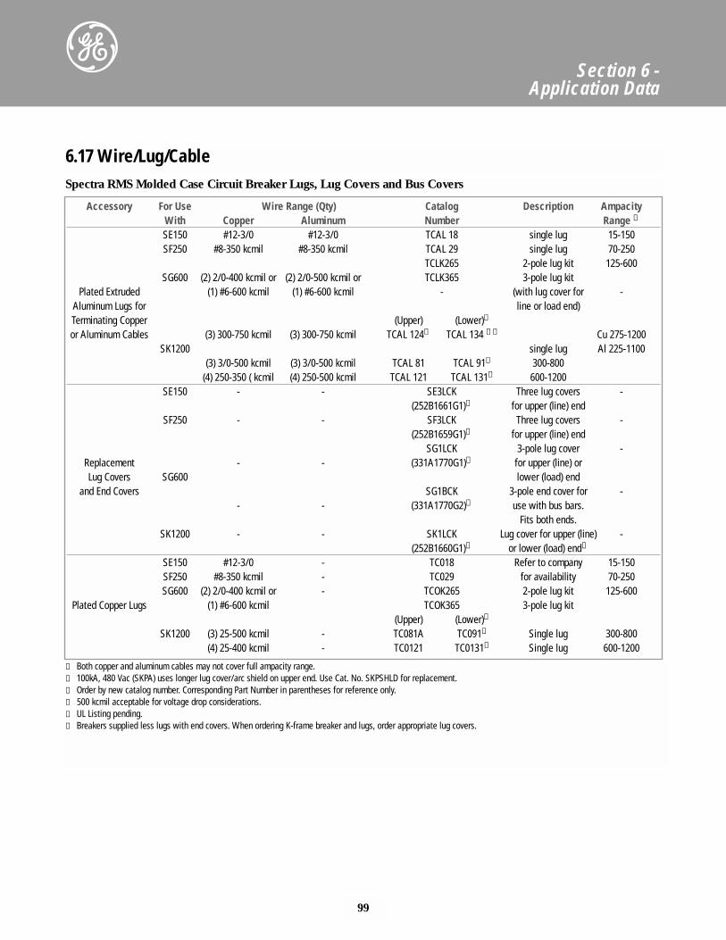
99
Section 6 - Application Data
6.17 Wire/Lug/CableSpectra RMS Molded Case Circuit Breaker Lugs, Lug Covers and Bus Covers
Accessory For Use Wire Range (Qty) Catalog Description AmpacityWith Copper Aluminum Number Range ①
SE150 #12-3/0 #12-3/0 TCAL 18 single lug 15-150SF250 #8-350 kcmil #8-350 kcmil TCAL 29 single lug 70-250
TCLK265 2-pole lug kit 125-600SG600 (2) 2/0-400 kcmil or (2) 2/0-500 kcmil or TCLK365 3-pole lug kit
Plated Extruded (1) #6-600 kcmil (1) #6-600 kcmil - (with lug cover for -Aluminum Lugs for line or load end)Terminating Copper (Upper) (Lower)➅
or Aluminum Cables (3) 300-750 kcmil (3) 300-750 kcmil TCAL 124➄ TCAL 134 ➄➅ Cu 275-1200SK1200 single lug Al 225-1100
(3) 3/0-500 kcmil (3) 3/0-500 kcmil TCAL 81 TCAL 91➅ 300-800(4) 250-350 ( kcmil (4) 250-500 kcmil TCAL 121 TCAL 131➅ 600-1200
SE150 - - SE3LCK Three lug covers -(252B1661G1)➂ for upper (line) end
SF250 - - SF3LCK Three lug covers -(252B1659G1)➂ for upper (line) end
SG1LCK 3-pole lug cover -Replacement - - (331A1770G1)➂ for upper (line) orLug Covers SG600 lower (load) end
and End Covers SG1BCK 3-pole end cover for -- - (331A1770G2)➁ use with bus bars.
Fits both ends.SK1200 - - SK1LCK Lug cover for upper (line) -
(252B1660G1)➂ or lower (load) end➁
SE150 #12-3/0 - TC018 Refer to company 15-150SF250 #8-350 kcmil - TC029 for availability 70-250SG600 (2) 2/0-400 kcmil or - TCOK265 2-pole lug kit 125-600
Plated Copper Lugs (1) #6-600 kcmil TCOK365 3-pole lug kit(Upper) (Lower)➅
SK1200 (3) 25-500 kcmil - TC081A TC091➅ Single lug 300-800(4) 25-400 kcmil - TC0121 TC0131➅ Single lug 600-1200
① Both copper and aluminum cables may not cover full ampacity range.➁ 100kA, 480 Vac (SKPA) uses longer lug cover/arc shield on upper end. Use Cat. No. SKPSHLD for replacement.➂ Order by new catalog number. Corresponding Part Number in parentheses for reference only.➃ 500 kcmil acceptable for voltage drop considerations.➄ UL Listing pending.➅ Breakers supplied less lugs with end covers. When ordering K-frame breaker and lugs, order appropriate lug covers.
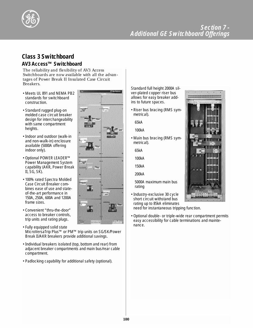
100
Section 7 - Additional GE Switchboard Offerings
Class 3 SwitchboardAV3 Access™ SwitchboardThe reliability and flexibility of AV3 AccessSwitchboards are now available with all the advan-tages of Power Break II Insulated Case CircuitBreakers.
• Meets UL 891 and NEMA PB2standards for switchboardconstruction.
• Standard rugged plug-onmolded case circuit breakerdesign for interchangeabilitywith same compartmentheights.
• Indoor and outdoor (walk-inand non-walk-in) enclosureavailable (5000A offeringindoor only).
• Optional POWER LEADER™Power Management Systemcapability (AKR, Power BreakII, SG, SK).
• 100% rated Spectra MoldedCase Circuit Breaker com-bines ease of use and state-of-the-art performance in150A, 250A, 600A and 1200Aframe sizes.
• Convenient “thru-the-door”access to breaker controls,trip units and rating plugs.
• Fully equipped solid stateMicroVersaTrip Plus™ or PM™ trip units on SG/SK/PowerBreak II/AKR breakers provide additional savings.
• Individual breakers isolated (top, bottom and rear) fromadjacent breaker compartments and main bus/rear cablecompartment.
• Padlocking capability for additional safety (optional).
Standard full height 2000A sil-ver-plated copper riser busallows for easy breaker add-ins to future spaces.
• Riser bus bracing (RMS sym-metrical).
65kA
100kA
• Main bus bracing (RMS sym-metrical).
65kA
100kA
150kA
200kA
5000A maximum main busrating
• Industry-exclusive 30 cycleshort circuit withstand busrating up to 85kA eliminatesneed for instantaneous tripping function.
• Optional double- or triple-wide rear compartment permitseasy accessibility for cable terminations and mainte-nance.
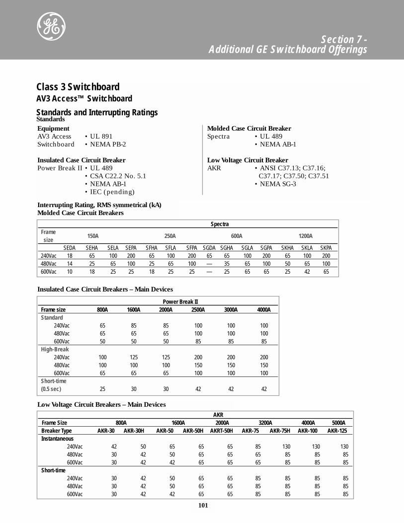
101
Section 7 - Additional GE Switchboard Offerings
EquipmentAV3 Access • UL 891Switchboard • NEMA PB-2
Insulated Case Circuit BreakerPower Break II • UL 489
• CSA C22.2 No. 5.1• NEMA AB-1• IEC (pending)
Molded Case Circuit BreakerSpectra • UL 489
• NEMA AB-1
Low Voltage Circuit BreakerAKR • ANSI C37.13; C37.16;
C37.17; C37.50; C37.51• NEMA SG-3
Class 3 SwitchboardAV3 Access™ Switchboard
Standards and Interrupting RatingsStandards
Power Break IIFrame size 800A 1600A 2000A 2500A 3000A 4000AStandard
240Vac 65 85 85 100 100 100480Vac 65 65 65 100 100 100600Vac 50 50 50 85 85 85
High-Break240Vac 100 125 125 200 200 200480Vac 100 100 100 150 150 150600Vac 65 65 65 100 100 100
Short-time(0.5 sec) 25 30 30 42 42 42
SpectraFrame
size150A 250A 600A 1200A
SEDA SEHA SELA SEPA SFHA SFLA SFPA SGDA SGHA SGLA SGPA SKHA SKLA SKPA240Vac 18 65 100 200 65 100 200 65 65 100 200 65 100 200480Vac 14 25 65 100 25 65 100 — 35 65 100 50 65 100600Vac 10 18 25 25 18 25 25 — 25 65 65 25 42 65
AKRFrame Size 800A 1600A 2000A 3200A 4000A 5000ABreaker Type AKR-30 AKR-30H AKR-50 AKR-50H AKRT-50H AKR-75 AKR-75H AKR-100 AKR-125Instantaneous
240Vac 42 50 65 65 65 85 130 130 130480Vac 30 42 50 65 65 65 85 85 85600Vac 30 42 42 65 65 65 85 85 85
Short-time240Vac 30 42 50 65 65 85 85 85 85480Vac 30 42 50 65 65 85 85 85 85600Vac 30 42 42 65 65 85 85 85 85
Low Voltage Circuit Breakers – Main Devices
Interrupting Rating, RMS symmetrical (kA)Molded Case Circuit Breakers
Insulated Case Circuit Breakers – Main Devices
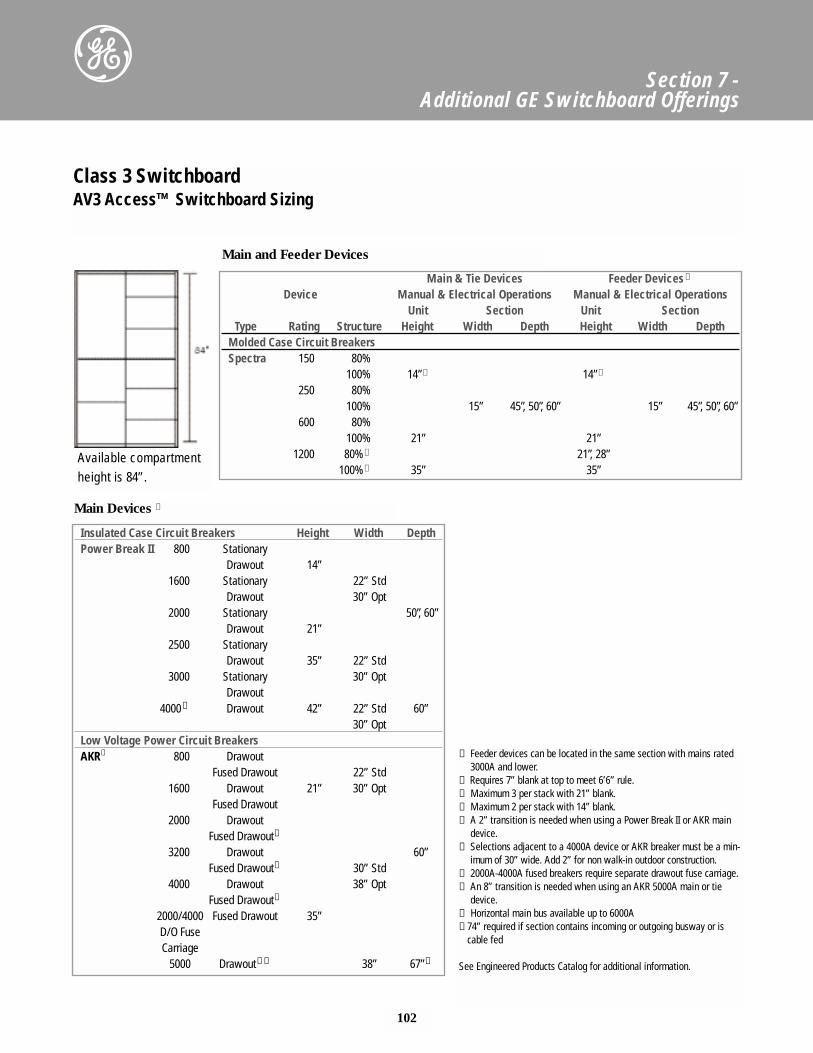
102
Section 7 - Additional GE Switchboard Offerings
Class 3 SwitchboardAV3 Access™ Switchboard Sizing
Main & Tie Devices Feeder Devices ➀
Device Manual & Electrical Operations Manual & Electrical OperationsUnit Section Unit Section
Type Rating Structure Height Width Depth Height Width DepthMolded Case Circuit BreakersSpectra 150 80%
100% 14”➁ 14”➁
250 80%100% 15” 45”, 50”, 60” 15” 45”, 50”, 60”
600 80%100% 21” 21”
1200 80%➂ 21”, 28”100%➃ 35” 35”
Insulated Case Circuit Breakers Height Width DepthPower Break II 800 Stationary
Drawout 14”1600 Stationary 22” Std
Drawout 30” Opt2000 Stationary 50”, 60”
Drawout 21”2500 Stationary
Drawout 35” 22” Std3000 Stationary 30” Opt
Drawout4000 ➅ Drawout 42” 22” Std 60”
30” OptLow Voltage Power Circuit BreakersAKR➅ 800 Drawout
Fused Drawout 22” Std1600 Drawout 21” 30” Opt
Fused Drawout2000 Drawout
Fused Drawout➆
3200 Drawout 60”Fused Drawout➆ 30” Std
4000 Drawout 38” OptFused Drawout➆
2000/4000 Fused Drawout 35”D/O FuseCarriage
5000 Drawout➇➈ 38” 67”➉
Main and Feeder Devices
Main Devices ➄
Available compartment height is 84”.
➀ Feeder devices can be located in the same section with mains rated3000A and lower.
➁ Requires 7” blank at top to meet 6’6” rule.➂ Maximum 3 per stack with 21” blank.➃ Maximum 2 per stack with 14” blank.➄ A 2” transition is needed when using a Power Break II or AKR main
device.➅ Selections adjacent to a 4000A device or AKR breaker must be a min-
imum of 30” wide. Add 2” for non walk-in outdoor construction.➆ 2000A-4000A fused breakers require separate drawout fuse carriage.➇ An 8” transition is needed when using an AKR 5000A main or tie
device.➈ Horizontal main bus available up to 6000A➉ 74” required if section contains incoming or outgoing busway or is
cable fed
See Engineered Products Catalog for additional information.

GE Industrial SystemsGeneral Electric Company41 Woodford Avenue, Plainville CT 06062www.GEindustrial.com
© 1999 General Electric CompanyGET-8032A 0899