Casting Material for Shipyards Etc
150
Rules for Classification and Construction II Materials and Welding 1 Metallic Materials 2 Steel and Iron Materials Edition 2009
Transcript of Casting Material for Shipyards Etc

8/10/2019 Casting Material for Shipyards Etc
http://slidepdf.com/reader/full/casting-material-for-shipyards-etc 1/150
8/10/2019 Casting Material for Shipyards Etc
http://slidepdf.com/reader/full/casting-material-for-shipyards-etc 2/150
The following Rules come into force on April 1st, 2009
Alterations to the preceding Edition are marked by beams at the text margin.
Germanischer Lloyd Aktiengesellschaft
Head Office
Vorsetzen 35, 20459 Hamburg, Germany
Phone: +49 40 36149-0
Fax: +49 40 [email protected]
www.gl-group.com
"General Terms and Conditions" of the respective latest edition will be applicable
(see Rules for Classification and Construction, I - Ship Technology, Part 0 - Classification and Surveys).
Reproduction by printing or photostatic means is only permissible with the consent of
Germanischer Lloyd Aktiengesellschaft.
Published by: Germanischer Lloyd Aktiengesellschaft, Hamburg
Printed by: Gebrüder Braasch GmbH, Hamburg

8/10/2019 Casting Material for Shipyards Etc
http://slidepdf.com/reader/full/casting-material-for-shipyards-etc 3/150
Table of Contents
Section 1 Steel Plates, Strips, Sections and Bars
A. General Rules ..................................................................... ........................................................ 1- 1
B. Normal and Higher Strength Hull Structural Steels ..................................................... .............. 1- 5
C. Unalloyed Steels for Welded Structures ..................................................................................... 1- 16
D. High-Strength Steels for Welded Structures ............................................................................... 1- 17
E. Steels for Steam Boilers and Pressure Vessels ................................................................... ....... 1- 21
F. Steels for Cargo Tanks ....................................................................................... ........................ 1- 23
G. Stainless Steels ................................................................ ........................................................... 1- 28
H. Clad Plates .................................................................. ......................................................... ...... 1- 30
I. Steels with Through Thickness Properties ....................................................................... .......... 1- 32
J. Steel-Aluminium Welding Joints ............................................................................................... 1- 34
Section 2 Steel Pipes
A. General Rules ..................................................................... ........................................................ 2- 1
B. Pipes for General Purpose ...................................................... .................................................... 2- 5
C. High-Temperature Steel Pipes ......................................................................... ........................... 2- 7
D. Pipes Tough at Sub-Zero Temperatures ................................ ..................................................... 2- 10
E. Stainless Steel Pipes ............................................................................ ....................................... 2- 14
Section 3 Forgings
A. General Rules ..................................................................... ........................................................ 3- 1
B. Forgings for Machine Construction and Shipbuilding ................................................................ 3- 5
C. Forgings for Crankshafts ............................................................... ............................................. 3- 6
D. Forgings for Gears ........................................................... ........................................................... 3- 10
E. Forgings for Boilers, Pressure Vessels, Process Equipment and Pipelines ................................ 3- 13
F. Steel Forgings Tough at Sub-Zero Temperatures ............................. .......................................... 3- 15
G. Non-destructive Testing of Forged Components ........................................................................ 3- 17
H. List of Forged Components for which Non-destructive Tests are Required ............................... 3- 23
I. Classifying of Inspection Zones for Magnetic Particle Testing (MT) ........................................ 3- 24
J. Classifying of Inspection Zones for Ultrasonic Testing (UT) .................................................... 3- 29
Section 4 Cast Steel
A. General Rules ..................................................................... ........................................................ 4- 1
B. Steel Castings for Machine Construction and Shipbuilding ....................................................... 4- 5
C. Steel Castings for Crankshafts and Connecting Rods ............................ ..................................... 4- 8
D. Steel Castings for Steam Boilers, Pressure Vessels and Pipelines ............................................. 4- 8
E. Steel Castings for Use at Low Temperatures .................................................................... ......... 4- 10
F. Stainless Steel Castings .................................................................... .......................................... 4- 13
G. Non-destructive Testing of Cast Steel Components ................................................................... 4- 16
H. List of Cast Steel Components for which Non-destructive Tests are Required .......................... 4- 28
I. Testing Instructions for Hull Structural Parts ........... ................................................................. . 4- 29
J. Testing Instruction for Diesel Engine Parts ...................................... .......................................... 4- 37
II - Part 1
GL 2009
Table of Contents Chapter 2
Page 3

8/10/2019 Casting Material for Shipyards Etc
http://slidepdf.com/reader/full/casting-material-for-shipyards-etc 4/150
Section 5 Cast Iron
A. General Rules ................................................................ ............................................................. . 5- 1
B. Nodular Cast Iron ..................................................... .......................................................... ........ 5- 3
C. Grey Cast Iron ........................................................... ......................................................... ......... 5- 8
Section 6 Fittings and Pressed Parts, Bolts and Nuts
A. Pressed Parts .......................................................... ............................................................ ......... 6- 1
B. Pipe Fittings .............................................................. ................................................................ .. 6- 4
C. Bolts and Nuts ...................................................................... ...................................................... . 6- 6
Chapter 2
Page 4
II - Part 1
GL 2009

8/10/2019 Casting Material for Shipyards Etc
http://slidepdf.com/reader/full/casting-material-for-shipyards-etc 5/150
Section 1
Steel Plates, Strips, Sections and Bars
A. General Rules
1. Scope
1.1 General rules to be applied in the manufac-ture and testing of hot-rolled plates, strips, sections(including hollow sections), rods and bars are con-tained in A.
1.2 Hot-rolled round bars intended for the manu-facture of shafts, tie rods and bolts are subject toSection 3, B.
1.3 Where stated in B. to J. of this Section, steelsconforming to national or international standards may
be used, provided that they satisfy the minimum re-quirements of these Rules.
2. Requirements to be met by manufacturers
Manufacturers wishing to supply products in accor-
dance with these Rules shall fulfil the requirements setout in Chapter 1 – Principles and Test Procedures,Section 1, C., and shall demonstrate this to GL prior tocommencing supplies. This applies also for manufac-turers of semi-finished products such as ingots, slabs,
blooms and billets.
3. Steelmaking process
3.1 The steels are to be manufactured by the basic oxygen process, the electric furnace process or by other methods approved by GL. On request, GLshall be informed of the steelmaking process used.
3.2 The steels may be cast in ingots (static cast-ing) or continuously.
Special casting processes require initial appraisal byGL.
4. Condition of supply and heat treatment
4.1 All products are to be supplied in the heattreated conditions described in the following individ-ual Sections, unless supply in the as-rolled condition isallowed.
This may be the case if, for instance, the product is toundergo further hot forming.
4.2 If the material is suitable, products may also be supplied in normalising rolled (controlled rolled) orthermo-mechanically rolled condition (see 4.3), pro-vided that the processes have been checked and ap-
proved by GL on the manufacturer's premises.
4.3 Definitions
The processes mentioned in 4.2 are defined as follows:
4.3.1 Normalising rolling
Normalising rolling (controlled rolling) is a rolling process involving final forming in a specific tempera-ture range which results in a material conditionequivalent to that achieved by normalising treatment;thus the desired values of the mechanical propertiesare preserved even after an additional normalisingtreatment.
Products supplied in this condition are designated bythe code NW.
4.3.2 Thermo-mechanical rolling
Thermo-mechanical rolling is a rolling process incor- porating careful monitoring of both the rolling tem- perature and also the reduction per pass. The greater proportion of reductions per pass is generally carriedout close to the upper transformation temperature Ar3
where rolling in the two-phase temperature range may be incorporated. Unlike normalising rolling, the prop-erties produced by thermo-mechanical rolling cannot
be reproduced by subsequent normalising or other heattreatments.
Products supplied in this condition are designated bythe code TM.
Accelerated cooling following TM rolling may take place if this process has been approved by GL. Thesame applies to tempering treatments following TMrolling.
Note on TM steels:
Any subsequent, continuous heating above 580 °C aswell as significant long holding times at lower tem-
peratures may impair the strength properties. Themanufacturer shall be consulted where there is a re-quirement to use temperatures above 580 °C.
Flame straightening will generally be possible. To thiseffect flame straightening may be carried out by using
flame lines/flame tracks on the surface up to 950 °C. A flame straightening by short time local through thick-
II - Part 1GL 2009
Section 1 Steel Plates, Strips, Sections and Bars Chapter 2Page 1–1
A

8/10/2019 Casting Material for Shipyards Etc
http://slidepdf.com/reader/full/casting-material-for-shipyards-etc 6/150
ness heating (hot wedge shapted spots, hot spots) maybe carried out by a heating up to 700 °C.
5. General characteristics of products
5.1 All products shall have a smooth rolled sur-face and shall be free from any defects liable to havemore than an insignificantly adverse effect on theirworkability and intended use, e.g. laminations, cracks,
blow holes, scabs and seams.
5.2 Unless otherwise stipulated by the purchaseror prescribed by GL, hot-rolled plates, wide flats andsections shall be subject to the delivery conditionsstipulated in EN 10163.
5.3 Unless otherwise specified or agreed, surface
defects may only be removed by grinding within the permitted tolerance on the minimum thickness. Thedepressions caused by grinding shall have a smoothtransition to the surrounding surface of the product.
6. Dimensions, dimensional and geometricaltolerances
6.1 Plates, strips and wide flats may be deliveredwith the minus tolerances shown in Table 1.1 or withno minus tolerance. Where no stipulations are made inthe following individual rules, e.g. for shipbuildingsteels in accordance with B., flat products for cargo
tanks in accordance with F. and clad plates in accor-dance with H. the permitted minus tolerance is to beagreed when the order is placed.
6.2 The thickness is to be measured at pointslocated at least 25 mm from the edge of the product.Local depressions due to flaws and grinding marksarising from the remedying of defects are not takeninto account, provided that they do not exceed thetolerances.
6.3 Unless otherwise agreed in the order, the provisions regarding form tolerances according to
EN 10029 apply.
6.4 For sections and bars, the dimensions and thedimensional and geometrical tolerances specified inthe standards apply.
7. General technical requirements
7.1 Chemical composition
The limit values specified in these Rules for thechemical composition apply to the melt analysis. Mi-nor positive or negative excesses beyond the limit
values, established by analysis of the product, areacceptable provided that they do not impair the prop-erties of the product and/or the tolerances specified inthe other relevant standards are not exceeded.
Table 1.1 Permitted minus tolerances for thethickness of plates and wide flats
Nominal thickness[mm]
Permitted minus
tolerances1
[mm]for class
A B C
≥ 3 < 5 – 0,4 – 0,3 0
≥ 5 < 8 – 0,4 – 0,3 0
≥ 8 < 15 – 0,5 – 0,3 0
≥ 15 < 25 – 0,6 – 0,3 0
≥ 25 < 40 – 0,8 – 0,3 0
≥ 40 < 80 – 1,0 – 0,3 0
≥ 80 < 150 – 1,0 – 0,3 0
≥ 150 ≤ 250 – 1,2 – 0,3 0
1 See also EN 10029.
7.2 Weldability
Steels conforming to these Rules shall be weldable byestablished workshop methods. Where applicable, thisincludes the measures necessary to ensure the qualityof the welds, e.g. preheating and/or post weld heattreatments.
7.3 Mechanical properties
The mechanical properties stated in these Rules shall be verified by means of tensile tests.
7.4 Notch impact energy
The notch impact energy specified for the individualsteels shall be fulfilled by the average value of threespecimens, one of which may produce a value below,though not less than 70 % of, the average value.
7.5 Other properties
Where special properties such as resistance to inter-crystalline corrosion, resistance to brittle fracture orhigh-temperature strength are prescribed for certaingroups of products, these shall be proved by appropri-ate tests, as necessary.
8. General instructions for testing
8.1 Testing of chemical composition
The manufacturer shall determine the chemical com-
position of each melt and shall submit a correspondingcertificate to the Surveyor. The chemical compositionspecified for the steel grade shall be shown in thecertificate.
Chapter 2Page 1–2
Section 1 Steel Plates, Strips, Sections and Bars II - Part 1GL 2009
A

8/10/2019 Casting Material for Shipyards Etc
http://slidepdf.com/reader/full/casting-material-for-shipyards-etc 7/150
8/10/2019 Casting Material for Shipyards Etc
http://slidepdf.com/reader/full/casting-material-for-shipyards-etc 8/150
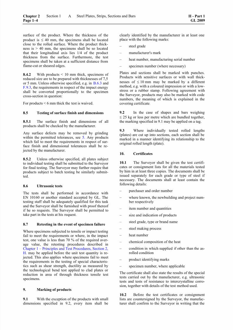
surface of the product. Where the thickness of the
product is ≤ 40 mm, the specimens shall be locatedclose to the rolled surface. Where the product thick-ness is > 40 mm, the specimens shall be so locatedthat their longitudinal axis lies 1/4 of the product
thickness from the surface. Furthermore, the testspecimens shall be taken at a sufficient distance fromflame-cut or sheared edges.
8.4.2 With products < 10 mm thick, specimens ofreduced size are to be prepared with thicknesses of 7,5or 5 mm. Unless otherwise specified, e.g. in B.6.3 andF.9.3, the requirements in respect of the impact energyshall be converted proportionally to the specimencross-section in question:
For products < 6 mm thick the test is waived.
8.5 Testing of surface finish and dimensions
8.5.1 The surface finish and dimensions of all products shall be checked by the manufacturer.
Any surface defects may be removed by grindingwithin the permitted tolerances, see 5. Any productswhich fail to meet the requirements in respect of sur-face finish and dimensional tolerances shall be re-
jected by the manufacturer.
8.5.2 Unless otherwise specified, all plates subjectto individual testing shall be submitted to the Surveyorfor final testing. The Surveyor may further require that
products subject to batch testing be similarly submit-ted.
8.6 Ultrasonic tests
The tests shall be performed in accordance withEN 10160 or another standard accepted by GL. Thetesting staff shall be adequately qualified for this taskand the Surveyor shall be furnished with proof thereofif he so requests. The Surveyor shall be permitted totake part in the tests at his request.
8.7 Retesting in the event of specimen failure
Where specimens subjected to tensile or impact testingfail to meet the requirements or where, in the impacttest, one value is less than 70 % of the required aver-age value, the retesting procedures described inChapter 1 – Principles and Test Procedures, Section 2,H. may be applied before the unit test quantity is re-
jected. This also applies where specimens fail to meetthe requirements in the testing of special characteris-tics such as shear strength, ductility as measured bythe technological bend test applied to clad plates orreduction in area of through thickness tensile testspecimens.
9. Marking of products
9.1 With the exception of the products with smalldimensions specified in 9.2, every item shall be
clearly identified by the manufacturer in at least one place with the following marks:
– steel grade
– manufacturer's mark
– heat number, manufacturing serial number
– specimen number (where necessary)
Plates and sections shall be marked with punches.Products with sensitive surfaces or with wall thick-
nesses of ≤ 10 mm may be marked by a differentmethod, e.g. with a coloured impression or with a low-stress or a rubber stamp. Following agreement withthe Surveyor, products may also be marked with codenumbers, the meaning of which is explained in thecovering certificate.
9.2 In the case of shapes and bars weighing
≤ 25 kg or less per metre which are bundled together,the marking specified in 9.1 may be applied on a tag.
9.3 Where individually tested rolled lengths(plates) are cut up into sections, each section shall bemarked in a manner identifying its relationship to theoriginal rolled length (plate).
10. Certificates
10.1 The Surveyor shall be given the test certifi-cates or consignment lists for all the materials tested
by him in at least three copies. The documents shall beissued separately for each grade or type of steel ifnecessary. The documents shall at least contain thefollowing details:
– purchaser and order number
– where known, the newbuilding and project num- ber respectively
– item number and quantities
– size and indication of products
– steel grade, type or brand name
– steel making process
– heat number
– chemical composition of the heat
– condition in which supplied if other than the as-rolled condition
– product identifying marks
– specimen number, where applicable
The certificate shall also state the results of the specialtests carried out by the manufacturer, e.g. ultrasonictests and tests of resistance to intercrystalline corro-sion, together with details of the test method used.
10.2 Before the test certificates or consignmentlists are countersigned by the Surveyor, the manufac-turer shall confirm to the Surveyor in writing that the
Chapter 2Page 1–4
Section 1 Steel Plates, Strips, Sections and Bars II - Part 1GL 2009
A
8/10/2019 Casting Material for Shipyards Etc
http://slidepdf.com/reader/full/casting-material-for-shipyards-etc 9/150
material was manufactured by an approved processand tested in accordance with GL Rules for Materials,and the requirements were satisfied. The name "Ger-manischer Lloyd" (GL) shall be mentioned in the testcertificate. The following wording of the declaration is
adequate for this purpose if it is stamped or printed onevery test certificate and/or consignment list togetherwith the manufacturer's name and is certified on themanufacturer's behalf by a works employee appointed
by him.
"We hereby declare that the material has been pro-duced by an approved method and has satisfied Rulesof GL for testing."
10.3 Where the steels are not produced and rolled by the same manufacturer, a certificate issued by thesteelmaker specifying at least the heat numbers andthe chemical compositions shall be handed to the
Surveyor.
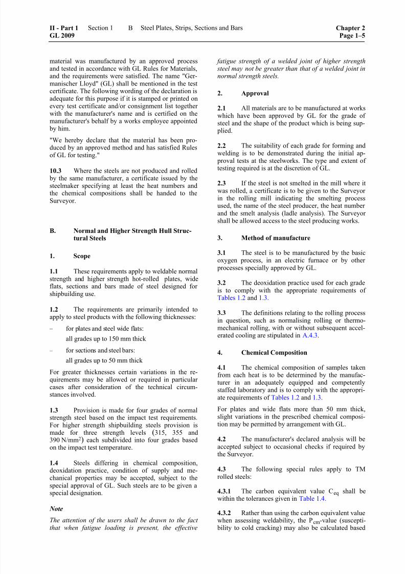
B. Normal and Higher Strength Hull Struc-tural Steels
1. Scope
1.1 These requirements apply to weldable normalstrength and higher strength hot-rolled plates, wideflats, sections and bars made of steel designed forshipbuilding use.
1.2 The requirements are primarily intended toapply to steel products with the following thicknesses:
– for plates and steel wide flats:
all grades up to 150 mm thick
– for sections and steel bars:
all grades up to 50 mm thick
For greater thicknesses certain variations in the re-quirements may be allowed or required in particularcases after consideration of the technical circum-stances involved.
1.3 Provision is made for four grades of normalstrength steel based on the impact test requirements.For higher strength shipbuilding steels provision ismade for three strength levels (315, 355 and390 N/mm2) each subdivided into four grades basedon the impact test temperature.
1.4 Steels differing in chemical composition,deoxidation practice, condition of supply and me-chanical properties may be accepted, subject to thespecial approval of GL. Such steels are to be given aspecial designation.
Note
The attention of the users shall be drawn to the factthat when fatigue loading is present, the effective
fatigue strength of a welded joint of higher strength steel may not be greater than that of a welded joint innormal strength steels.
2. Approval
2.1 All materials are to be manufactured at workswhich have been approved by GL for the grade ofsteel and the shape of the product which is being sup-
plied.
2.2 The suitability of each grade for forming andwelding is to be demonstrated during the initial ap-
proval tests at the steelworks. The type and extent oftesting required is at the discretion of GL.
2.3 If the steel is not smelted in the mill where itwas rolled, a certificate is to be given to the Surveyor
in the rolling mill indicating the smelting processused, the name of the steel producer, the heat numberand the smelt analysis (ladle analysis). The Surveyorshall be allowed access to the steel producing works.
3. Method of manufacture
3.1 The steel is to be manufactured by the basicoxygen process, in an electric furnace or by other
processes specially approved by GL.
3.2 The deoxidation practice used for each gradeis to comply with the appropriate requirements ofTables 1.2 and 1.3.
3.3 The definitions relating to the rolling processin question, such as normalising rolling or thermo-mechanical rolling, with or without subsequent accel-erated cooling are stipulated in A.4.3.
4. Chemical Composition
4.1 The chemical composition of samples takenfrom each heat is to be determined by the manufac-turer in an adequately equipped and competentlystaffed laboratory and is to comply with the appropri-ate requirements of Tables 1.2 and 1.3.
For plates and wide flats more than 50 mm thick,slight variations in the prescribed chemical composi-tion may be permitted by arrangement with GL.
4.2 The manufacturer's declared analysis will beaccepted subject to occasional checks if required bythe Surveyor.
4.3 The following special rules apply to TMrolled steels:
4.3.1 The carbon equivalent value Ceq shall bewithin the tolerances given in Table 1.4.
4.3.2 Rather than using the carbon equivalent valuewhen assessing weldability, the Pcm-value (suscepti-
bility to cold cracking) may also be calculated based
II - Part 1GL 2009
Section 1 Steel Plates, Strips, Sections and Bars Chapter 2Page 1–5
B

8/10/2019 Casting Material for Shipyards Etc
http://slidepdf.com/reader/full/casting-material-for-shipyards-etc 10/150
on the following formula:
[ ]
cm
Si Mn Cu NiP C
30 20 20 60
Cr Mo V
5 B %20 15 10
= + + + + +
+ + +
In such cases, the Pcm value shall be agreed with GL.
5. Condition of supply
The condition in which all products are supplied shallcorrespond to the data given in Tables 1.5 and/or 1.6.
6. Mechanical properties
6.1 For tensile testing either the upper yieldstrength R eH or, where this is not stipulated, the 0,2
per cent proof stress R p0,2 is to be determined and the
material is considered to satisfy the requirements ifone of these values meets or exceeds the prescribedminimum value for the yield strength R e.
6.2 The results obtained from tensile tests shallcomply with the appropriate requirements of Tables1.7 and 1.8.
Table 1.2 Chemical composition and deoxidation practice for normal strength steels
Grade GL–A GL–B GL–D GL–E
For t ≤ 50 mm
any method except 1
rimmed steel
For t ≤ 50 mm
any method except
rimmed steel
For t ≤ 25 mm
killed,Deoxidation
practicefor t > 50 mm
killed
for t > 50 mm
killed
for t > 25 mm
fully killed an fine
grain treated
Fully killed and
fine grain treated
Chemical
composition (%)
(ladle analysis) 4, 7, 8
Carbon plus 1/6 of the manganese content is not to exceed 0,40 %
Cmax 0,212
0,21 0,21 0,18Mnmin 2,5 × C 0,80 3 0,60 0,70
Simax 0,50 0,35 0,35 0,35
Pmax 0,035 0,035 0,035 0,035
Smax 0,035 0,035 0,035 0,035
Al (acid soluble) min –– –– 0,015 5, 6 0,015 6
t = Material thickness
1 Grade GL–A sections up to a thickness of 12,5 mm may be accepted in rimmed steel subject to the special approval of GL.
2 Max. 0,23 % for sections.
3 When Grade GL-B steel is impact tested the minimum manganese content may be reduced to 0,60 %
4 When any grade of steel is supplied in the thermo-mechanically rolled condition variations in the specified chemical composition may
be allowed or required.
5 For Grade GL–D steel over 25 mm thick.
6 For Grade GL-D steel over 25 mm thick and for Grade GL-E steel, the total aluminium content may be calculated in place of the acid
soluble part. In such cases, the total aluminium content may not be less than 0,020 %. GL may also specify a maximum limit for
aluminium. Other grain refining elements may also be permitted subject to approval.
7 In the melt, the maximum values of the following elements may not be exceeded:
– Cu : 0,30 %
– Cr : 0,20 %
– Ni : 0,40 %
– Mo : 0,08 %
8
Where the manufacturing process demands the addition of additional elements, their contents are to be indicated in the manufacturer'scertificate.
Chapter 2Page 1–6
Section 1 Steel Plates, Strips, Sections and Bars II - Part 1GL 2009
B
8/10/2019 Casting Material for Shipyards Etc
http://slidepdf.com/reader/full/casting-material-for-shipyards-etc 11/150
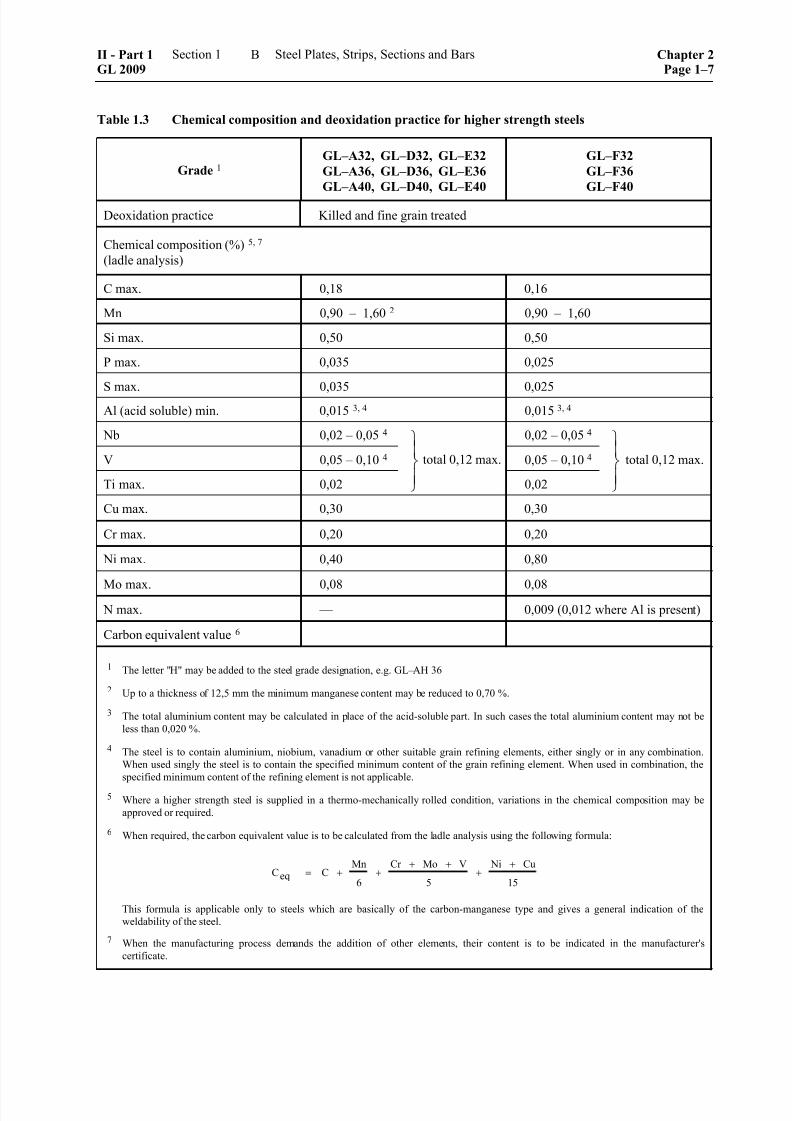
Table 1.3 Chemical composition and deoxidation practice for higher strength steels
Grade 1 GL–A32, GL–D32, GL–E32
GL–A36, GL–D36, GL–E36
GL–A40, GL–D40, GL–E40
GL–F32
GL–F36
GL–F40
Deoxidation practice Killed and fine grain treated
Chemical composition (%) 5, 7
(ladle analysis)
C max. 0,18 0,16
Mn 0,90 – 1,60 2 0,90 – 1,60
Si max. 0,50 0,50
P max. 0,035 0,025
S max. 0,035 0,025Al (acid soluble) min. 0,015 3, 4 0,015 3, 4
Nb 0,02 – 0,05 4 0,02 – 0,05 4
V 0,05 – 0,10 4 0,05 – 0,10 4
Ti max. 0,02
⎫⎪⎬⎪⎭
0,02
⎫⎪⎬⎪⎭
Cu max. 0,30 0,30
Cr max. 0,20 0,20
Ni max. 0,40 0,80
Mo max. 0,08 0,08
N max. –– 0,009 (0,012 where Al is present)
Carbon equivalent value 6
1 The letter "H" may be added to the steel grade designation, e.g. GL–AH 36
2 Up to a thickness of 12,5 mm the minimum manganese content may be reduced to 0,70 %.
3 The total aluminium content may be calculated in place of the acid-soluble part. In such cases the total aluminium content may not be
less than 0,020 %.
4 The steel is to contain aluminium, niobium, vanadium or other suitable grain refining elements, either singly or in any combination.
When used singly the steel is to contain the specified minimum content of the grain refining element. When used in combination, the
specified minimum content of the refining element is not applicable.
5 Where a higher strength steel is supplied in a thermo-mechanically rolled condition, variations in the chemical composition may be
approved or required.
6 When required, the carbon equivalent value is to be calculated from the ladle analysis using the following formula:
Ceq CMn Cr Mo V Ni Cu
= + + + +
+ +
6 5 15
This formula is applicable only to steels which are basically of the carbon-manganese type and gives a general indication of the
weldability of the steel.
7 When the manufacturing process demands the addition of other elements, their content is to be indicated in the manufacturer's
certificate.
total 0,12 max. total 0,12 max.
II - Part 1GL 2009
Section 1 Steel Plates, Strips, Sections and Bars Chapter 2Page 1–7
B
8/10/2019 Casting Material for Shipyards Etc
http://slidepdf.com/reader/full/casting-material-for-shipyards-etc 12/150
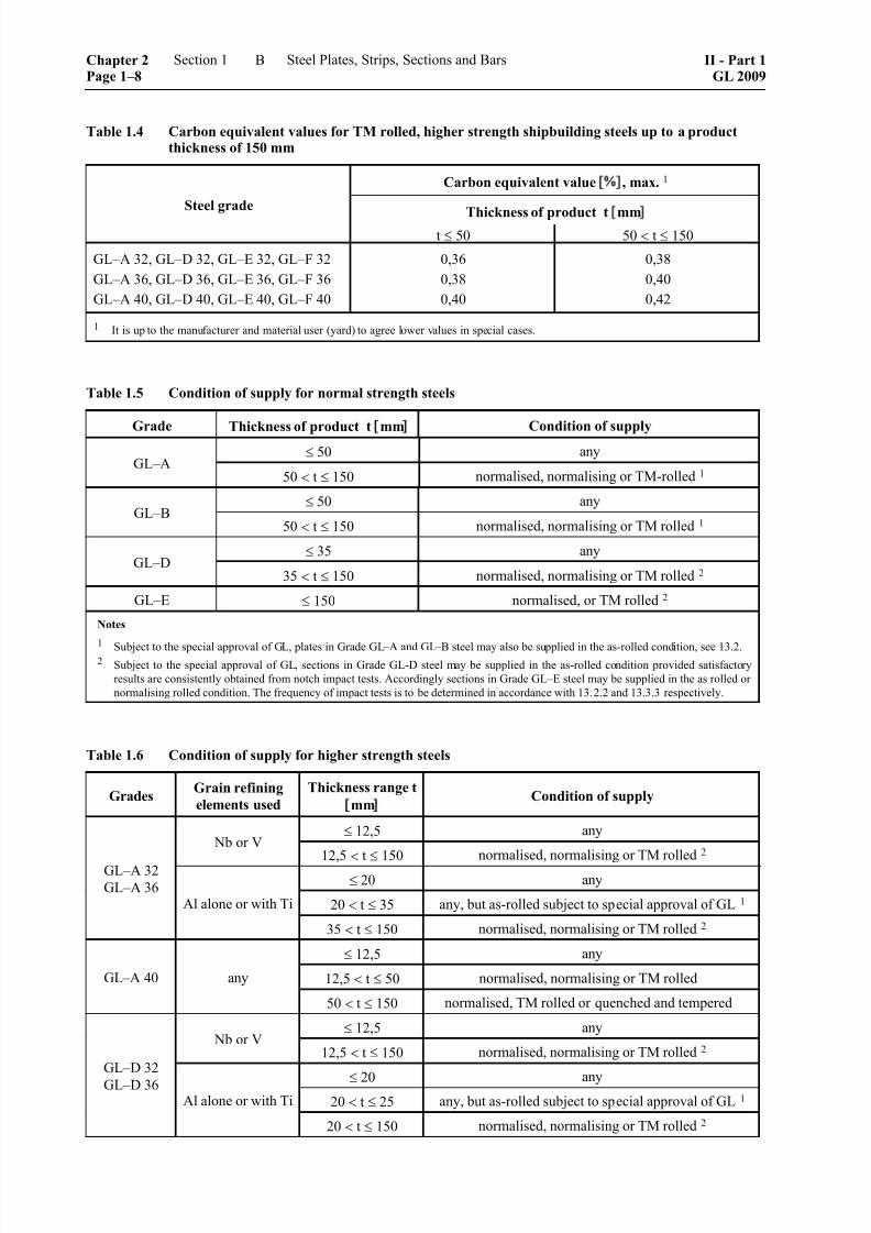
Table 1.4 Carbon equivalent values for TM rolled, higher strength shipbuilding steels up to a productthickness of 150 mm
Carbon equivalent value ], max. 1
Thickness of product t mm] Steel grade
t ≤ 50 50 < t ≤ 150
GL–A 32, GL–D 32, GL–E 32, GL–F 32
GL–A 36, GL–D 36, GL–E 36, GL–F 36
GL–A 40, GL–D 40, GL–E 40, GL–F 40
0,36
0,38
0,40
0,38
0,40
0,42
1 It is up to the manufacturer and material user (yard) to agree lower values in special cases.
Table 1.5 Condition of supply for normal strength steels
Grade Thickness of product t mm] Condition of supply≤ 50 any
GL–A50 < t ≤ 150 normalised, normalising or TM-rolled 1
≤ 50 anyGL–B
50 < t ≤ 150 normalised, normalising or TM rolled 1
≤ 35 anyGL–D
35 < t ≤ 150 normalised, normalising or TM rolled 2
GL–E ≤ 150 normalised, or TM rolled 2
Notes
1 Subject to the special approval of GL, plates in Grade GL–A and GL–B steel may also be supplied in the as-rolled condition, see 13.2.2 Subject to the special approval of GL, sections in Grade GL-D steel may be supplied in the as-rolled condition provided satisfactory
results are consistently obtained from notch impact tests. Accordingly sections in Grade GL–E steel may be supplied in the as rolled or
normalising rolled condition. The frequency of impact tests is to be determined in accordance with 13.2.2 and 13.3.3 respectively.
Table 1.6 Condition of supply for higher strength steels
GradesGrain refining
elements used
Thickness range t
mm] Condition of supply
≤ 12,5 any Nb or V
12,5 < t ≤ 150 normalised, normalising or TM rolled 2
≤ 20 any
20 < t ≤ 35 any, but as-rolled subject to special approval of GL 1
GL–A 32
GL–A 36Al alone or with Ti
35 < t ≤ 150 normalised, normalising or TM rolled 2
≤ 12,5 any
12,5 < t ≤ 50 normalised, normalising or TM rolledGL–A 40 any
50 < t ≤ 150 normalised, TM rolled or quenched and tempered
≤ 12,5 any Nb or V
12,5 < t ≤ 150 normalised, normalising or TM rolled 2
≤ 20 any20 < t ≤ 25 any, but as-rolled subject to special approval of GL 1
GL–D 32
GL–D 36Al alone or with Ti
20 < t ≤ 150 normalised, normalising or TM rolled 2
Chapter 2Page 1–8
Section 1 Steel Plates, Strips, Sections and Bars II - Part 1GL 2009
B

8/10/2019 Casting Material for Shipyards Etc
http://slidepdf.com/reader/full/casting-material-for-shipyards-etc 13/150
Table 1.6 Condition of supply for higher strength steels (continued)
GradesGrain refining
elements used
Thickness range t
mm] Condition of supply
≤ 50 normalised, normalising or TM rolledGL–D 40 any
50 < t ≤ 150 normalised, TM rolled or quenched and tempered
≤ 50 normalised or TM rolled 2 GL–E 32
GL–E 36any
50 < t ≤ 150 normalised or TM rolled
GL–E 40 any ≤ 150 normalised, TM rolled or quenched and tempered
GL–F 32
GL–F 36
GL–F 40
any ≤ 150 normalised, TM rolled or quenched and tempered 3
1 The frequency of impact tests is to be in accordance with 13.2.2.
2 Subject to the special approval of GL, sections in Grade GL–A 32, GL–A 36, GL–D 32 and GL–D 36 steels may be supplied in as-
rolled condition provided satisfactory results are consistently obtained from notch impact tests. Accordingly, sections in grade GL–E 32
and GL–E 36 steels may be supplied in as-rolled or normalising rolled condition. The frequency of notch impact tests is to be in
accordance with 13.2.2 and 13.2.3 respectively.
3 Subject to special approval of GL, sections in Grade GL–F 32 and GL–F 36 steels with thickness ≤ 50 may be supplied in as-rolled
condition or normalising rolled condition. The frequency of notch impact tests is to be in accordance with 13.3.3.
Table 1.7 Mechanical properties for normal strength steels
Notched bar impact energy
KV[J]
min.
Yield
strengthR eH
Tensile
strengthR m
Elongation 1
A
( )o oat L =5,65 STest
temp.
t 50 [mm] 50 t 70 [mm] 70 t 150 [mm]
Grade
[N/mm2]
min.
[N/mm2] [%]
min.
[°C]long. transv. long. transv. long. transv.
GL–A +20 –– –– 34 4 24 4 41 4 27 4
GL–B 0 27 3 20 3 34 24 41 27
GL–D –20 27 20 34 24 41 27
GL–E
235 400–520 2 22
–40 27 20 34 24 41 27
t = thickness of product [mm]
1 Required elongation for flat tensile test specimens with gauge length Lo = 200 mm, width = 25 mm and a thickness equal to the productthickness:
Thickness of product t [mm] ≤ 5> 5
≤ 10
> 10
≤ 15
> 15
≤ 20
> 20
≤ 25
> 25
≤ 30
> 30
≤ 40
> 40
≤ 50
Elongation A200 mm [%] 14 16 17 18 19 20 21 22
2 For Grade GL–A sections the upper limit for the specified tensile strength range may be exceeded at the discretion of GL, irrespectiveof product thickness.
3
Notch impact tests are generally not required for Grade GL–B steels with thickness of 25 mm or less.4 For Grade GL–A products with thickness in excess of 50 mm, notch impact tests are not required provided that the steel has been fine
grain treated and normalised. TM rolled steels may also be supplied without notch impact testing provided that GL has waived the need.
II - Part 1GL 2009
Section 1 Steel Plates, Strips, Sections and Bars Chapter 2Page 1–9
B

8/10/2019 Casting Material for Shipyards Etc
http://slidepdf.com/reader/full/casting-material-for-shipyards-etc 14/150
8/10/2019 Casting Material for Shipyards Etc
http://slidepdf.com/reader/full/casting-material-for-shipyards-etc 15/150
7. Freedom from defects and repair of sur-face defects
7.1 General characteristics
7.1.1 All products shall satisfy the requirementsapplicable to general characteristics set out in A.5.1. Unless otherwise agreed, the surface finish of the
products shall be subject to standard EN 10163, speci-fications relating to the surface finish of hot-rolledsteel products (plate, steel wide flat and sections),Class A, or equivalent national or international stan-dard, however, grinding of defects may only be car-ried out within the limits given in 7.2.
7.1.2 Notwithstanding the provisions of A.5.3, surface defects may be removed not only by grinding
but also by welding according to the principles stated below, provided that the defects in question are iso-
lated, of locally limited extent and the sum of thedefective areas covers not more than 2 % of the rele-vant face of the product.
7.2 Repairs by grinding
The manufacturer may, at his discretion, remove sur-face defects by grinding, provided that the depth ofmaterial ground away does not exceed 3 mm in rela-tion to the nominal thickness of the product and pro-vided also that at least 93 % of the nominal thicknessremains. In addition, the depressions caused by thegrinding shall have a smooth transition to the sur-rounding surface of the product.
7.3 Repairs by welding
Defects which cannot be removed by grinding may berepaired by chipping and/or grinding with subsequentwelding, provided that the Surveyor has consented tothe repair and that the following requirements are met.
7.3.1 After chipping or grinding the defect, theremaining thickness shall be equal to at least 80 % ofthe nominal thickness. The remaining thickness may
be less than this limit value only in exceptional caseswhere the specific application of the product is notthereby impaired.
7.3.2 All welds shall be performed by trainedwelders using approved methods and electrodes with acontrolled low hydrogen content. At least one layer ofweld metal is to be welded in excess which shallthereafter be ground flush to the surface level.
7.3.3 Wherever possible, products which are to besupplied in the normalised condition shall be welded
prior to the heat treatment. If welding is required afternormalising an additional treatment may be requested.
Products which are supplied thermo-mechanicallytreated or hot-rolled are to receive stress-relief heattreatment after welding, if appropriate further process-ing cannot be ensured.
7.3.4 The repaired items shall be submitted to theSurveyor for final inspection and freedom from de-
fects shall be proved by a suitable non-destructivemethod.
7.3.5 For every repair weld, the manufacturer shall prepare a report containing details of the size andlocation of the defects, the welding method used andany heat treatment applied, and shall hand this reportto the Surveyor.
8. Dimensions, dimensional and geometricaltolerances
The provisions of A.6. are applicable. With regard toflat products (plates and steel wide flat) for shipbuild-ing use, Class B given in Table 1.1 may be consideredas the permitted lower deviation from the nominalthickness. This means that the permitted lower devia-tion for all product thicknesses is a uniform – 0,3 mm.
9. Material identification
9.1 The manufacturer is required to set up anidentification system for ingots, slabs and finished
products so that the material can be traced back as faras smelting.
9.2 The Surveyor is to be allowed every facilityin order to carry out this trace-back procedure as ap-
propriate.
10. Testing and inspection
10.1 Test facilities
The manufacturer is required to allow the Surveyoraccess to all works departments and to provide all thenecessary facilities as may be required to establish theapproved manufacturing process, the selection of testmaterial, supervision of tests in accordance with therules and also to establish the precision of the testequipment.
10.2 Test methods
The prescribed tests and surveys shall be conducted atthe place of manufacture prior to despatch of products.The test specimens and test methods shall complywith the information given in Chapter 1 – Principles
and Test Procedures, Section 2. Unless otherwiseagreed with GL, the specimens shall be selected by theSurveyor, marked and tested in his presence.
10.3 Tensile testing of specimens taken in thedirection of thickness
Where plates and steel wide flats with thicknessesranging from 15 to 150 mm are ordered with require-ments as to the direction of thickness, tensile testspecimens shall be prepared and tested with their axis
perpendicular to the surface of the product as de-scribed in I.
10.4 Non-destructive testing
10.4.1 Where plates and steel wide flats are orderedwith an ultrasonic test certificate, the tests are to beexecuted in accordance with a standard approved by
II - Part 1GL 2009
Section 1 Steel Plates, Strips, Sections and Bars Chapter 2Page 1–11
B
8/10/2019 Casting Material for Shipyards Etc
http://slidepdf.com/reader/full/casting-material-for-shipyards-etc 16/150
GL, e.g. EN 10160. The quality class is to be stipu-lated when the order is placed.
10.4.2 The seams of welded hollow sections of hullstructural steel are to be subjected to non-destructive
testing over their entire length.
10.4.2.1 Electrical welded hollow sections
The weld seam of hollow sections is to be examinedaccording to one of the following European standards:
– EN 10246-3, acceptance category E4, exceptthat the technique of rotating pipes or with rotat-ing saddle coils is not permitted
– EN 10246-5, acceptance category F5, or EN10246-8, acceptance category U5
10.4.2.2 Submerged-arc welded hollow sections
The weld seam of hollow sections is to be examinedaccording to acceptance category U4 in accordancewith EN 10246-10, image quality class R2.
Butt welds serving to connect strip or plate lengths byspiral submerged-arc welding have to be examinedover their entire length according to the same test
procedure and shall satisfy the same acceptance crite-ria as the main weld seam.
10.5 Testing of surface finish and dimensions
Inspections of surface finish and dimensional checks
are the responsibility of the rolling mill. Acceptancetesting by the Surveyor does not release the manufac-turer from this responsibility.
11. Test material
11.1 Definitions
11.1.1 "Piece" denotes the rolled product which has been rolled directly from an ingot, billet or slab into a plate, section or bar.
11.1.2 "Batch" denotes a test batch, made up of
products of the same kind and originating from thesame heat, which has been submitted as a whole fortesting.
11.2 Test section
11.2.1 The material which has been combined in one batch (one test batch) for testing shall have the sameshape e.g. plate, steel wide flat, section, originate fromthe same heat and be delivered in the same condition.
11.2.2 The test sections shall be representative of thematerial and may only be cut from the test piece fol-lowing the final heat treatment - unless there are tech-nical reasons why they should not be.
11.2.3 Test sections may not be heat treated sepa-rately.
11.2.4 The removal of test sections is subject to therules laid down in A.8.2.
12. Specimens for mechanical tests
12.1 Tensile test samples
The dimensions of the tensile test samples are to beselected from those given in Chapter 1 – Principlesand Test Procedures, Section 2, D. Full thickness flattensile test specimens should generally be selected asthe test thickness for plates, steel wide flats and sec-tions. Round tensile test specimens may be used wherethe thickness of the product exceeds 40 mm or in thecase of bars and similar products. By way of an alter-native to these specimens, full section specimens of asuitable length may also be tested in the case of small
bars and sections.
12.2 Impact test specimens
Impact test specimens shall comply with the Charpy Vspecimen shape and be taken horizontally with thelong side of the specimen 2 mm below the rollingsurface. They shall be positioned so that their axes areeither "longitudinal" or "transverse" to the main direc-tion of rolling as shown in Tables 1.7 and 1.8. Thenotch shall be milled in the side of the specimen sothat the latter’s axis is vertical to the surface of the
product. The position of the notch may not be lessthan 25 mm from one flame-cut edge or one shearedge. Where the thickness of the product exceeds
40 mm, the impact test specimens shall be taken insuch a way that the axis of the specimen is positionedat 1/4 of the product thickness.
13. Number of test specimens
13.1 Number of tensile tests
For each batch presented, except where speciallyagreed by GL, one tensile test specimen is to be takenfrom one piece (max. weight 50 t from the same heat).Where the weight of finished material is greater than50 tonnes, one extra test specimen is to be taken from
a different piece from each 50 tonnes or fractionthereof. Provision shall be made for additional speci-mens for every variation of 10 mm in the thickness ordiameter of products from the same heat.
13.2 Number of impact tests
(except for Grades GL–E, GL–E 32,GL–E 36,GL–E 40, GL–F 32, GL–F 36and GL–F 40)
13.2.1 Except where otherwise specially agreed byGL, for each batch presented (max. 50 t from the sameheat), at least one set of three Charpy V-notch testspecimens is to be made from one piece. Where the
weight of finished material is greater than 50 tonnes,one extra set of three test specimens is to be madefrom a different piece from each 50 tonnes or fractionsthereof.
Chapter 2Page 1–12
Section 1 Steel Plates, Strips, Sections and Bars II - Part 1GL 2009
B
8/10/2019 Casting Material for Shipyards Etc
http://slidepdf.com/reader/full/casting-material-for-shipyards-etc 17/150
From plates of grades GL–A 40 and GL-D 40 inquenched and tempered condition, one set of impact-tests per heat treatment length is to be taken.
Where plates, except for those in grade GL–A steel,are supplied in thicknesses greater than 50 mm in thenormalising rolled condition, the test batch fromwhich specimens are taken is no greater than 25 ton-nes or fractions thereof.
13.2.2 When, subject to the special approval of GL,material is supplied in the as rolled condition, thefrequency of impact tests is to be increased to one setfrom each batch of 25 tonnes or fractions thereof. Thesame applies when plates of grade GL-A steel aresupplied in thicknesses greater than 50 mm in the as-rolled condition. In this case, one set of three impacttest specimens shall be taken for each 50 tonnes orfractions thereof.
13.2.3 The piece selected for the preparation of thetest specimens is to be the thickest in the batch.
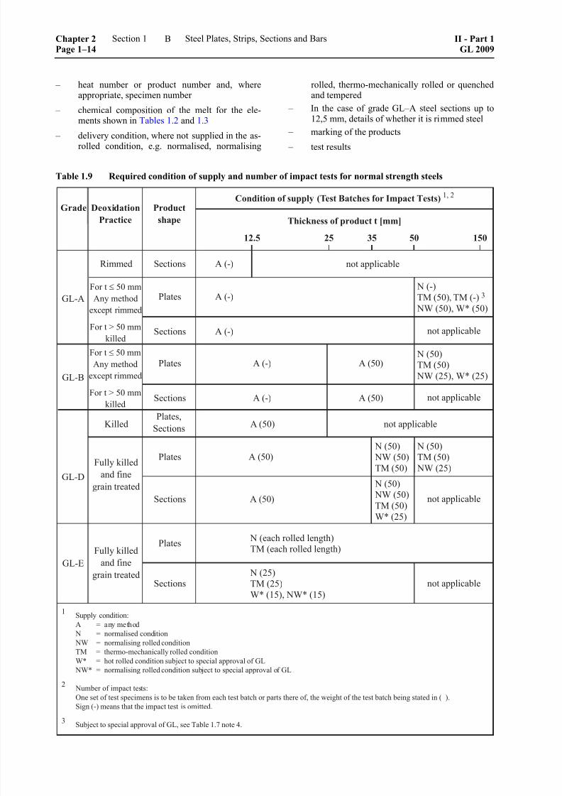
13.2.4 The test batch quantity depending on supplycondition and thickness of product is shown in Tables1.9 and 1.10.
13.3 Number of impact tests for Grades GL-E,GL–E 32, GL–E 36, GL–E 40, GL–F 32,GL–F 36 and GL–F 40
13.3.1 For plates supplied in the normalised or TM-rolled condition, one set of specimens is to be taken
from each rolled length. In the case of quenched andtempered plates, one set of specimens is to be takenfrom each heat treatment length.
13.3.2 For sections one set of specimens is to betaken from each test unit of 25 tonnes or fractionsthereof.
13.3.3 When, subject to the special approval of GL,sections other than those in grade GL–E 40 and GL–F40, are supplied in the as rolled or normalising rolledcondition, one set of test specimens is to be taken fromeach batch of 15 tonnes or fractions thereof.
13.3.4 The specimens taken as described in 13.3.1 or13.3.3 above are to be taken from the thickest piece ineach batch.
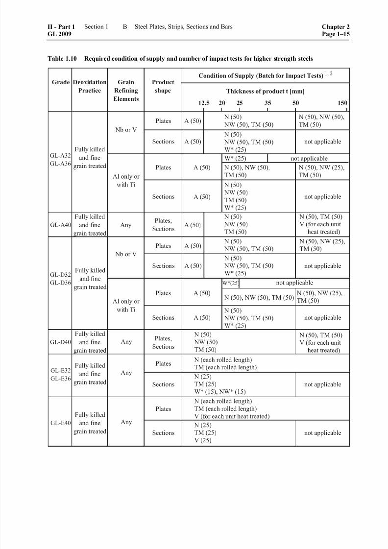
13.3.5 The test batch quantity depending on supplycondition and thickness of product is shown in Tables1.9 and 1.10.
14. Re-tests
14.1 Where the requirements are not satisfied in atensile test, or where the average from three impacttest samples fails to meet the conditions, or where anindividual value from a notch impact test does not
meet the requirements, re-tests are to be carried out asstipulated in Chapter 1 – Principles and Test Proce-dures, Section 2, H. In this case, the conditions speci-fied therein are to be satisfied.
15. Branding
15.1 Every finished piece is to be clearly marked by the maker in at least one place with GL's brand andthe following particulars:
– identification mark for the grade steel (e.g. GL– A, GL–A 36)
– Steels which have been specially approved byGL and which differ from these requirements(see 1.4) are to have the letter "S" after theabove identification mark (e.g. GL–A36 S, GL-ES)
– Material supplied in the thermo-mechanicallycontrolled processed condition is to have the let-ters TM added after the identification mark (e.g.GL–E 36 TM)
– name or initials to identify the steelworks
– heat or other number to identify the piece
– if required by the purchaser, his order number orother identification mark
15.2 The above particulars, but excluding themanufacturer's name or trade mark, where this is em-
bossed on finished products, are to be encircled with paint or otherwise marked so as to be easily recogniz-able.
15.3 Where a number of low-weight products are
securely combined in packages or bundles, it is suffi-cient, subject to approval by GL, to mark only theuppermost piece in the package or robust tag which issecurely fastened to the bundle.
15.4 When a product already bears GL brand buthas not satisfied the test conditions, said brand shall beunequivocally removed by the manufacturer.
16. Certificates
16.1 The manufacturer shall hand over to the Sur-veyor either works acceptance test certificates (e.g. in
accordance with EN 10204-3.1) or despatch docu-ments for the products accepted by him. Said docu-mentation shall be in triplicate at least. Documentationis to be produced separately for each grade of steeland shall contain the following particulars:
– purchaser and order number
– where known, the newbuilding and projectnumber respectively
– item numbers and quantities
– size and indication of products
– identification of rolling mill
– steel grade
– weight of products
II - Part 1GL 2009
Section 1 Steel Plates, Strips, Sections and Bars Chapter 2Page 1–13
B
8/10/2019 Casting Material for Shipyards Etc
http://slidepdf.com/reader/full/casting-material-for-shipyards-etc 18/150
– heat number or product number and, whereappropriate, specimen number
– chemical composition of the melt for the ele-ments shown in Tables 1.2 and 1.3
– delivery condition, where not supplied in the as-rolled condition, e.g. normalised, normalising
rolled, thermo-mechanically rolled or quenchedand tempered
– In the case of grade GL–A steel sections up to12,5 mm, details of whether it is rimmed steel
– marking of the products
– test results
Table 1.9 Required condition of supply and number of impact tests for normal strength steels
Chapter 2Page 1–14
Section 1 Steel Plates, Strips, Sections and Bars II - Part 1GL 2009
B
8/10/2019 Casting Material for Shipyards Etc
http://slidepdf.com/reader/full/casting-material-for-shipyards-etc 19/150
Table 1.10 Required condition of supply and number of impact tests for higher strength steels
II - Part 1GL 2009
Section 1 Steel Plates, Strips, Sections and Bars Chapter 2Page 1–15
B

8/10/2019 Casting Material for Shipyards Etc
http://slidepdf.com/reader/full/casting-material-for-shipyards-etc 20/150
Table 1.10 Required condition of supply and number of impact tests for higher strength steels (continued)
16.2 Before the acceptance test certificates ordespatch documents are signed by the Surveyor, themanufacturer shall hand over written confirmation thatthe steel has been produced by an approved methodhas successfully passed the tests prescribed in the
presence of the Surveyor or his representative ap- pointed by GL. In this regard, the following text may
be also accepted, either stamped or printed on thecertificate or despatch documents, and shall be veri-fied by one of the manufacturer's authorised agents:
"We hereby declare that the material has been pro-duced by an approved method and has satisfied theRules of GL for testing".
C. Unalloyed Steels for Welded Structures
1. Scope
1.1 These Rules apply to flat products, sections
and bars made from unalloyed steels with minimum
nominal yield strengths up to and including 355 N/mm2
which are to be used for welded structures, e.g. in ma-chinery manufacture or in shipbuilding.
1.2 Rolled bars for the manufacture of shafts,shanks, studs, bolts and other rotating parts are gov-erned by Section 3, B.
2. Suitable steels
The following steels may be used with the require-ments laid down in the relevant standards:
2.1 Steels conforming to EN 10025, EN 10210and EN 10219 grades as follows:
– S235: all grades
Note
The grades S235 JR and S235 JR G1 accordingto EN 10025 : 1990 + A1 : 1993 are excluded
from application.
– S275: all grades
– S355: all grades
Chapter 2Page 1–16
Section 1 Steel Plates, Strips, Sections and Bars II - Part 1GL 2009
C

8/10/2019 Casting Material for Shipyards Etc
http://slidepdf.com/reader/full/casting-material-for-shipyards-etc 21/150
2.2 Weldable fine-grained structural steels con-forming to EN 10025-3, in the grades:
– S275 N, S 275 NL, S355 N, S355 NL(normalised or normalising rolled)
and conforming to EN 10025-4 in the grades:
– S275 M, S275 ML, S355 M, S355 ML(thermo-mechanically rolled)
2.3 Other steels after their suitability has beendetermined by GL, provided that they satisfy the fol-lowing minimum requirements:
2.3.1 The chemical composition [%] of the ladleanalysis shall not exceed the following limit values:
C Mn Si P S Cu Cr Ni Mo0,22 1,70 0,55 0,040 0,040 0,30 0,20 0,40 0,08
In addition, fine grain treated structural steels shallhave an adequate content of grain refining elements,e.g. Al, Nb, V or Ti.
2.3.2 The elongation A5 shall be at least 20 % intests with longitudinal specimens and 18 % in testswith transverse specimens.
2.3.3 For fine grain treated structural steels, animpact energy of not less than 27 J (average value)
shall be achieved in tests with longitudinal Charpy V-notch specimens at a testing temperature of
– 20 °C, for products supplied in normalised, nor-malising rolled or thermo-mechanicallyrolled condition
0 °C, for products supplied in as rolled condition.
3. Condition of supply and heat treatment
Flat products made of fine grain treated structuralsteels are to be supplied in normalised, normalising
rolled or thermo-mechanically rolled condition. For allother products, the data in the standards apply, unlessotherwise specified in the order.
4. Dimensions, dimensional and geometrical
tolerances
A.6. applies, with the following addition:
For the minus tolerance applicable to the nominalthickness, the values stated under Class A in Table 1.1 apply to plates, strips and wide flats, unless otherwisespecified in the purchase order.
5. Testing and scope of tests
The following tests shall be performed:
5.1 Test of chemical composition
The manufacturer shall determine the chemical com- position of each heat and shall issue a relevant certifi-cate.
5.2 Tensile test
5.2.1 The mechanical properties shall be verified by tensile test.
For the purpose of taking specimens, products of thesame shape shall be formed according to heat andwithin the thickness ranges relevant to the yieldstrength into test batches of not more than 40 t. Atensile test specimen shall be taken from the thickestitem in the test batch. In the case of plates and wide
flats with a width of ≥ 600 mm, this shall be posi-tioned transverse to the rolling direction. In other
products, the test specimen may lie transverse or par-allel to the rolling direction.
5.2.2 Where plates are to be tested individually,this shall be specially stipulated in the order.
5.3 Notched bar impact test
All products made of fine grain treated steels shall besubjected to notched bar impact tests performed withlongitudinal Charpy V-notch specimens at the testtemperatures specified in the standards or in 2.3.3. Where, in the case of plates, individual testing has not
been agreed, a set of test specimens shall be taken
from the thickest piece in the test batch in accordancewith 5.2.1.
Testing shall be performed for products with a thick-
ness of ≥ 6 mm.
5.4 Testing of surface finish and dimensions
The surface finish and dimensions of all products shall be checked by the manufacturers. At the request of theSurveyor, the products shall then be submitted to himfor final inspection.
D. High-Strength Steels for Welded Struc-tures
1. Scope
1.1 These Rules apply to plates and wide flats upto 70 mm thick made of weldable high-strengthquenched and tempered steels. The application ofthese Rules to products with larger thicknesses shall
be specially agreed with Germanischer Lloyd (GL).The same applies if products other than plates andwide flats, e. g. sections and pipes, are to be supplied
in accordance with these Rules.
1.2 Steels falling within the scope of these Rulesare classed into 6 groups indicated by the nominal
II - Part 1GL 2009
Section 1 Steel Plates, Strips, Sections and Bars Chapter 2Page 1–17
D

8/10/2019 Casting Material for Shipyards Etc
http://slidepdf.com/reader/full/casting-material-for-shipyards-etc 22/150
yield strengths 420, 460, 500, 550, 620 and 690 N/mm2. Each group is further subdivided into thegrades A, D, E and F based on the temperature fornotched bar impact testing.
1.3 Steels which diverge from these Rules, e.g.with regard to their nominal yield strength, their me-chanical properties and their chemical composition,may not be used without the special approval of GL.
1.4 Steels conforming to EN 10025-3 and -4 mayalso be used in place of grades GL–A 420, GL–D 420,GL–A 460 and GL–D 460, viz:
– for grades GL–A 420 and GL–D 420:
S420 N and S420 NL, EN 10025-3S420 M and S420 ML, EN 10025-4
– for grades GL–A 460 and GL–D 460:
S460 N and S460 NL, EN 10025-3S460 M and S460 ML, EN 10025-4
2. Approval
The steels shall be approved by GL. For this purpose,the steel manufacturer shall send GL a material speci-fication containing the required information, such aschemical composition, manufacturing process, me-chanical properties, condition of supply, as well asrecommendations for welding, hot or cold forming,and heat treatment. GL reserves the right to requireinitial approval testing.
The material manufacturer shall verify the weldabilityof each grade of steel by appropriate documentation
possibly in connection with welding tests.
3. Requirements
3.1 Manufacturing process
The steels shall be manufactured in works approved by GL by the basic oxygen process, in electric arcfurnaces, or by another process approved by GL. Theyshall be cast in killed condition and fine grain treated.
3.2 Chemical composition
3.2.1 The chemical composition shall satisfy therequirements stated in the authorized specification andin Table 1.11.
Elements used for alloying and fine grain treatmentare to be indicated in the manufacturer’s specification.
3.2.2 To assess weldability, sensitivity to coldcracking may be calculated from the ladle analysisaccording to the following formula:
P C Si Mn Cu Ni
Cr Mo VB
cm = + + + + +
+ + +
30 20 20 60
20 15 105 %
The maximum permitted value is to be agreed withGL and shall be indicated in the authorised specifica-tion.
3.3 Heat treatment
The steels shall be supplied in quenched and temperedcondition. However, for grades GL–A 420, GL– D 420, GL–E 420, GL–F 420 and also for GL–A 460,GL– D 460, GL–E 460 and GL–F 460, with productthicknesses up to 50 m, normalising or normalisingrolling is permitted where the required properties can
be achieved thereby. This is to be demonstrated forapproval testing. The same applies to thermo-mechanically rolled steels up to 70 mm thickness withnominal yield strength up to 500 N/mm2.
3.4 Mechanical properties
The requirements applicable to the mechanical proper-ties and the impact energy shall conform to the data inTable 1.12.
3.5 General condition of products
A.5. applies. In addition, it should be noted that:
– Procedures for repair welding and reportingthereon shall be approved by GL.
– If defects are removed by grinding, the thicknessremaining underneath the ground area shall bewithin the thickness tolerance.
3.6 Dimensions, dimensional and geometricaltolerances
A.6. applies, with the following addition:
For the minus tolerance applicable to the nominalthickness, the values stated under Class A in Table 1.1 apply, unless otherwise specified in the order.
4. Testing
4.1 Testing of chemical composition
The manufacturer shall determine the composition ofevery heat and shall issue a relevant certificate.
4.2 Tensile test
4.2.1 From every piece heat-treated in a unit, atleast one tensile test specimen shall be taken andtested. If plates are heat-treated by continuous proc-esses, special arrangements may be made with regardto the number of tests required and the making of thetest specimens.
In the case of products which are not quenched andtempered, one tensile test specimen is to be taken for
each rolled length.4.2.2 Test specimens are to be cut with theirlongitudinal axes perpendicular to the final directionof rolling, except in the case of sections and wide
Chapter 2Page 1–18
Section 1 Steel Plates, Strips, Sections and Bars II - Part 1GL 2009
D

8/10/2019 Casting Material for Shipyards Etc
http://slidepdf.com/reader/full/casting-material-for-shipyards-etc 23/150
Table 1.11 Chemical composition of quenched and tempered steels
Grade, with
nominal yield
strengths
grade Maximum Content of Elements 1
[%]
R eH [N/mm2] C Si Mn P S N
420 to 690
GL–A
GL–D
GL–E
GL–F
0,21
0,20
0,20
0,18
0,55
0,55
0,55
0,55
1,70
1,70
1,70
1,70
0,035
0,030
0,030
0,025
0,035
0,030
0,030
0,025
0,020
0,020
0,020
0,020
1 Elements used for alloying and fine grain treatment are to be as details in the approved specification.
flats < 600 mm in width, where longitudinal testspecimens are to be taken. For other product forms,the tensile test specimens may be taken in either thelongitudinal or the transverse direction as agreed withGL. Normally, flat tensile test specimens are to beused. The tensile-test specimens may be taken fromthe full or the half product thickness, however, onesurface side shall be maintained. For thicknessesabove 30 mm round tensile test specimens may beused, the axis of which shall lie at a distance of 1/4 ofthe product thickness from the surface.
4.3 Impact test
4.3.1 From each piece as heat treated or, in the caseof products from each rolling length which have not been quenched and tempered, at least one set of threeCharpy V-notch impact test specimens in accordancewith Chapter 1 – Principles and Test Procedures, Sec-tion 2, E.2. is to be taken and tested. For continuousheat treated plates special consideration may be givento the number and location of test specimens required.
4.3.2 Unless otherwise accepted by GL, the V-notch impact test specimens for plates and wide flats≥
600 mm are to be taken with their axes transverse tothe main rolling direction. For other product forms theimpact tests are to be in the longitudinal direction. Thespecimens' axes shall be positioned at a distance of 1/4of the product thickness from the surface or as near as possible to this position.
4.3.3 For grade GL-A steel products, the number ofimpact test specimens may be reduced by agreementwith GL, where equivalent results are obtained duringtesting.
4.4 Through thickness tensile test
If required by GL, through thickness tensile tests areto be performed using test specimens taken at rightangles to the surface of the product in accordance withI.
4.5 Surface inspection and dimensions
The manufacturer shall inspect the condition of thesurface and the dimensions of the product and shallthen submit the products to the Surveyor for inspec-tion.
4.6 Non-destructive testing
4.6.1 Where plates and wide flats are ordered witha certificate of ultrasonic examination, the tests are to be carried out according to a standard accepted by GL,e.g. EN 10160. The quality class is to be defined at thetime of the order.
4.6.2 The seams of welded hollow sections of hullstructural steel are to be subjected to non-destructivetesting over their entire length.
4.6.2.1 Electrical welded hollow sections
The weld seam of hollow sections is to be examinedaccording to one of the following European standards:
– EN 10246-3, acceptance category E4, exceptthat the technique of rotating pipes or with rotat-ing saddle coils is not permitted
– EN 10246-5, acceptance category F5, or EN10246-8, acceptance category U5
4.6.2.2 Submerged-arc welded hollow sections
The weld seam of hollow sections is to be examinedaccording to acceptance category U4 in accordancewith EN 10246-10, image quality class R2.
Butt welds serving to connect strip or plate lengths by
spiral submerged-arc welding have to be examinedover their entire length according to the same test procedure and shall satisfy the same acceptance crite-ria as the main weld seam.
II - Part 1GL 2009
Section 1 Steel Plates, Strips, Sections and Bars Chapter 2Page 1–19
D

8/10/2019 Casting Material for Shipyards Etc
http://slidepdf.com/reader/full/casting-material-for-shipyards-etc 24/150
Table 1.12 Mechanical and technological properties for products with 70 mm maximum thickness
Impact energy Elongation 3
( )o oat L = 5,65 S
A [%]
min.
KV[J]
min.
Grades
Yield strength 1, 2
R eH
[N/mm2]
min.
Tensile strength
R m
[N/mm2]
long. transv.
Test temp.
[°C]
long. transv.
GL–A 420 0
GL–D 420 – 20
GL–E 420 – 40
GL–F 420
420 530 – 680 20 18
– 60
42 28
GL–A 460 0
GL–D 460 – 20
GL–E 460 – 40
GL–F 460
460 570 – 720 19 17
– 60
46 31
GL–A 500 0
GL–D 500 – 20
GL–E 500 – 40
GL–F 500
500 610 – 770 18 16
– 60
50 33
GL–A 550 0
GL–D 550 – 20
GL–E 550 – 40
GL–F 550
550 670 – 830 18 16
– 60
55 37
GL–A 620 0
GL–D 620 – 20
GL–E 620 – 40
GL–F 620
620 720 – 890 17 15
– 60
62 41
GL–A 690 0
GL–D 690 – 20
GL–E 690 – 40
GL–F 690
690 770 – 940 16 14
– 60
69 46
1 Where the yield strength R eH does not mark in the tensile test, the 0,2 % proof stress R p0,2 is applicable.
2 The permissible ratio between yield strength and tensile strength is to be agreed between the manufacturer and GL.
4 Where flat tensile test specimens 25 mm wide and with a gauge length of 200 mm are used, the minimum requirements in respect ofelongation are to be obtained from Table 1.13.
Chapter 2Page 1–20
Section 1 Steel Plates, Strips, Sections and Bars II - Part 1GL 2009
D

8/10/2019 Casting Material for Shipyards Etc
http://slidepdf.com/reader/full/casting-material-for-shipyards-etc 25/150
Table 1.13 Minimum values in respect of elongation when using specimens 25 mm wide and with a gaugelength of 200 mm
Elongation A200 mm [%]
Nominal yield strength Thickness of product t [mm]
R eH [N/mm2] ≤ 10 >
≤
10
15
>
≤
15
20
>
≤
20
25
>
≤
25
40
>
≤
40
50
>
≤
50
70
420
460
500
550
620
690
11
11
10
10
9
9
13
12
11
11
11
10
14
13
12
12
12
11
15
14
13
13
12
11
16
15
14
14
13
12
17
16
15
15
14
13
18
17
16
16
15
14
4.7 Retest procedures
4.7.1 If one of the tensile tests fails to meet therequirements two additional test specimens are to betaken from the same position of the piece and sub-
jected to the test. The piece will be accepted, if bothadditional tests are satisfactory.
4.7.2 When the average value of the impact testfails to meet the requirements or more than one valueis below the required average value or when one valueis below 70 % of the specified average value, the
procedure described in Chapter 1 – Principles and TestProcedures, Section 2, H. is to be followed.
5. Marking
Every finished piece is to be clearly marked by themaker in at least one piece with GL brand and thefollowing particulars:
– Marks of the manufacturer
– Unified identification mark for the grade of steel(e.g. GL–E 620) or manufacturer's trade name
– Heat number, plate number or equivalent identi-fication mark.
The entire markings are to be encircled with paint orotherwise marked so as to be easily recognized.
E. Steels for Steam Boilers and PressureVessels
1. Scope
These Rules apply to flat products made from ferriticsteels, which are intended for the manufacture ofsteam boilers, pressure vessels, heat exchangers andother process equipment.
2. Approved steel grades
The materials listed below may be used:
2.1 Flat products made of steels used for pressurevessels conforming to EN 10028-2 "Alloyed andUnalloyed High Temperature Steels".
2.2 Flat products made of steels used for pressurevessels conforming to EN 10028-3, "Weldable fine-grained structural steels, normalised".
2.3 Flat products made of GL-steels used for pressure vessels according to Table 1.14 and 1.15. Forthe 0,2 % proof stress at elevated temperatures, Table1.16 applies.
2.4 Flat products made of other steels, providedthat their suitability for the intended purpose and their
properties have been proved to GL. For this, the fol-lowing requirements are to be satisfied:
2.4.1 The elongation (A) shall have the minimumvalues which characterise the grade of steel, as speci-fied in the GL report, but shall be not less than 16 %.
2.4.2 The impact energy shall meet or exceed therequirements of EN 10028-2 and -3 respectively forflat products of the same strength, see Table 1.14. Inthe case of plates to be used for shell rings and heads,the manufacturer and the steel user shall ensure thatthe values required for the final condition can be com-
plied with.
2.4.3 Proof of weldability shall be furnished by themanufacturer. Details of preheating, temperature con-trol during welding and heat treatment after weldingshall be furnished by the manufacturer.
2.4.4 The yield strength at elevated temperatureand, where necessary, the long-time rupture stress
properties at elevated temperature shall be verified bythe manufacturer if they are different from Table 1.16.
II - Part 1GL 2009
Section 1 Steel Plates, Strips, Sections and Bars Chapter 2Page 1–21
E

8/10/2019 Casting Material for Shipyards Etc
http://slidepdf.com/reader/full/casting-material-for-shipyards-etc 26/150
Table 1.14 Mechanical and technological properties of flat products made of GL-steels used forpressure vessels 1
Notched bar
impact energy
Steel grade Normaldelivery
condition
Yield strength
R eH andR p0,2 respectively
[N/mm2]
min.
Tensile strength
R m
[N/mm2]
Elongation
A
[%]
min.
Test temp.
[°C]
KV
[J]
min.
transv.
GL-P235W N 235 360 to 480 25 0 34
GL-P265W N 265 410 to 530 23 0 34
GL-P295W N 295 460 to 580 22 0 34
GL-P355W N 355 510 to 650 21 0 34
1 N = normalized, T = tempered.
Table 1.15 Chemical composition of GL-steels used for pressure vessels
Chemical composition [%]Steel grade
C Si Mn P S Altot. Cr Mo
all ≤ 0,23 ≤ 0,55 0,60–1,70 ≤ 0,025 ≤ 0,015 ≥ 0,020 ≤ 0,30 ≤ 0,08
Table 1.16 0,2 %-Proof stress at elevated temperatures for flat products made of GL-steels used for pres-
sure vessels
R p0,2-Yield strength [N/mm2]
min.
Temperature [°C]Steel grade
50 100 150 200 250 300 350 400
GL-P235W 227 214 198 182 167 153 142 133
GL-P265W 256 241 223 205 188 173 160 150
GL-P295W 285 268 249 228 209 192 178 167
GL-P355W 343 323 299 275 252 232 214 202
2.5 For plates to be used for shell rings andheads, the following additional requirements apply:
For steels for welded boiler drums, the impact energy
shall be 31 J at ± 0 °C in tests performed on the fin-
ished component, if in the case of plate thicknesses
≥ 50 mm the yield strength of these steels is
≥ 310 N/mm2 at room temperature. This energy value
is an average for three individual tests with (trans-
verse) Charpy V-notch specimens, in which none ofthe individual values may be more than 15 % lower
than the stated average of 31 J. The stated impactenergy value at ± 0 °C is a minimum requirement. In
addition, the individual steels shall exhibit their char-
acteristic impact energies.
2.6 Plates to be manufactured into fire tubes shall
exhibit adequate formability - elongation (A) ≥ 20 %
at 20 °C .
3. Condition of supply and heat treatment
The products shall be delivered in the heat-treatedconditions specified in the standards and/or in theexpert's report, unless they are to be further processedat elevated temperature.
Chapter 2Page 1–22
Section 1 Steel Plates, Strips, Sections and Bars II - Part 1GL 2009
E

8/10/2019 Casting Material for Shipyards Etc
http://slidepdf.com/reader/full/casting-material-for-shipyards-etc 27/150
4. Dimensions, dimensional and geometricaltolerances
A.6. applies with the following addition: The minustolerances for the nominal thickness shall be as statedunder Class B in Table 1.1. If lower minus tolerancesare required for technical reasons, this shall be statedin the order.
5. Testing and scope of tests
The following tests shall be performed:
5.1 Testing of chemical composition
The manufacturer shall determine the chemical com- position of each heat and issue a relevant certificate.
5.2 Tensile test
The mechanical properties shall be verified by tensiletesting. Test specimens shall be taken from the prod-ucts transverse to the direction of rolling in the follow-ing quantity:
– For sheet and plate, the specimens shall be takenas follows:
– unalloyed steel sheet ≤ 50 mm thick:
- one specimen from one end of eachrolled length
– unalloyed steel plate > 50 mm thick:
- one specimen from one end if the rolledlength is ≤ 15 m, one specimen fromeach end if the rolled length is > 15 m
– alloy steels with rolled length ≤ 7 m:
- one specimen from one end, one speci-men from each end if the rolled length is> 7 m.
– For sheets made from hot-rolled wide strip, atleast one specimen shall be taken from the outerend of each coil.
5.3 Tensile test at elevated temperature
The 0,2 % proof stress is to be verified at elevatedtemperature. A tensile test at elevated temperatureshall be performed for each heat. The test temperatureshall be 300 °C, unless no other temperature is speci-fied in the order.
5.4 Notched bar impact test
5.4.1 All products with thicknesses ≥ 6 mm shall be impact tested using Charpy V-notch specimens atthe test temperature of 0 °C. The specimens shall betaken from the products transverse to the direction of
rolling. The number of sets (each of 3 specimens)required for this purpose shall be determined in thesame way as the number of tensile test specimens
prescribed in 5.2.
The test temperatures for flat products complying withEN 10025 are given in the standard.
For other steels as per 2.4, the test temperature will bestipulated in the GL approval.
5.5 Testing of surface finish and dimensions
The surface finish and dimensions of all products shall be checked by the manufacturer. The products shallalso be submitted to the Surveyor for final inspection;as far as possible, the undersides of the products shall
be inspected at the same time.
5.6 Non-destructive testing
Where specified in the order or required in specialcases, e.g. in the case of products subject to require-ments in the thickness direction in accordance with I., an ultrasonic test shall be carried out in accordance
with A.8.6.
6. Marking of products
The manufacturer shall mark the products in the pre-scribed manner, see EN 10028-1. In the case of plateswhich are not supplied in bundles, the marking shall
be applied 200 to 400 mm from the bottom end insuch a way that, looked at from the bottom end of the
plate, the characters are upright and therefore indicatethe direction of rolling.
7. Strength parameters for calculations
The strength parameters for calculations are:
7.1 For flat products conforming to EN 10028-2and -3, the values stated in these standards.
For flat products made of GL-steels used for pressurevessels according to 2.3, the values stated in Table1.16.
7.2 For flat products made of other steels as per2.4, the values approved by GL.
7.3 The strength parameters indicated in the
above standards for 100 °C are valid up to 120 °C. Inthe other ranges, the values are to be determined bylinear interpolation between the stated values, e.g. for180 °C between 100 °C and 200 °C; rounding up isnot allowed.
F. Steels for Cargo Tanks
1. Scope
1.1 These Rules apply to flat products made from
– fine-grained structural steels,
– high strength, quenched and tempered fine-grained structural steels,
II - Part 1GL 2009
Section 1 Steel Plates, Strips, Sections and Bars Chapter 2Page 1–23
F
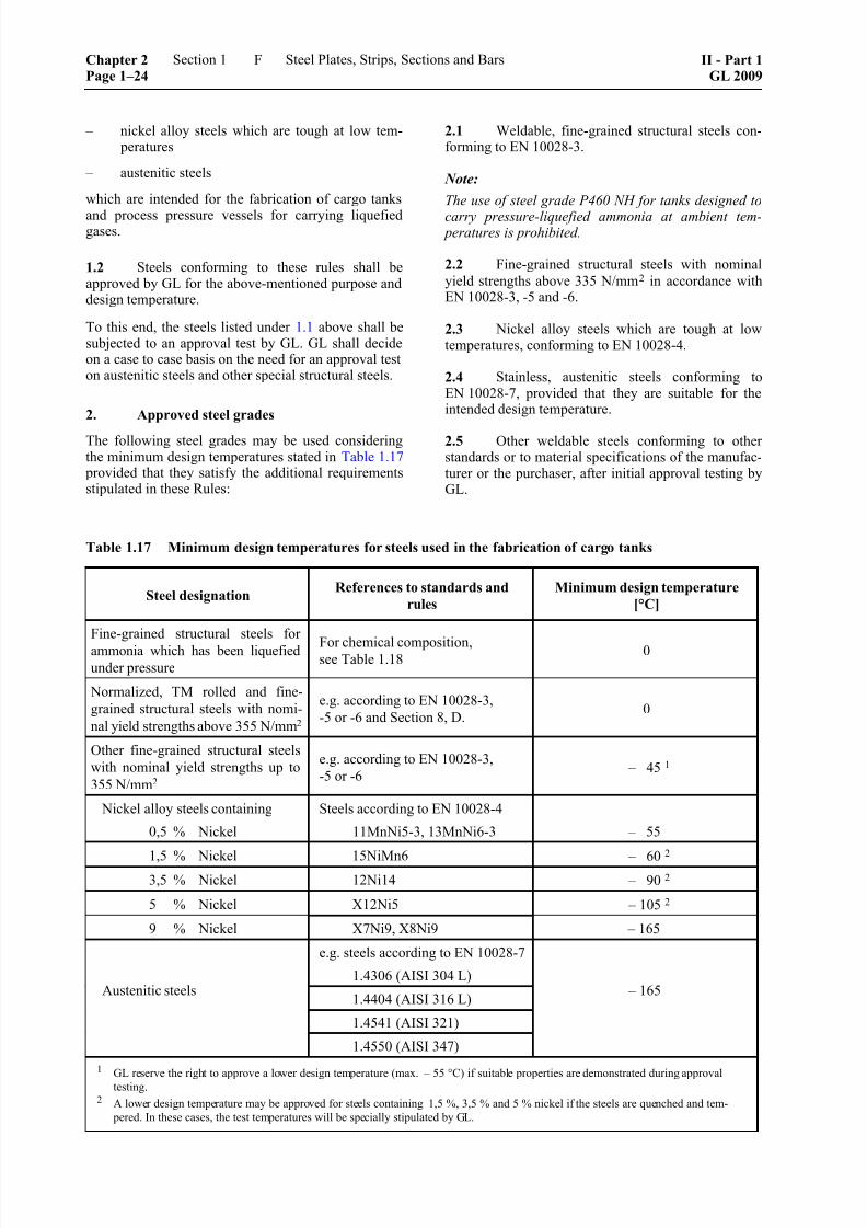
8/10/2019 Casting Material for Shipyards Etc
http://slidepdf.com/reader/full/casting-material-for-shipyards-etc 28/150
– nickel alloy steels which are tough at low tem- peratures
– austenitic steels
which are intended for the fabrication of cargo tanks
and process pressure vessels for carrying liquefiedgases.
1.2 Steels conforming to these rules shall beapproved by GL for the above-mentioned purpose anddesign temperature.
To this end, the steels listed under 1.1 above shall besubjected to an approval test by GL. GL shall decideon a case to case basis on the need for an approval teston austenitic steels and other special structural steels.
2. Approved steel grades
The following steel grades may be used consideringthe minimum design temperatures stated in Table 1.17
provided that they satisfy the additional requirementsstipulated in these Rules:
2.1 Weldable, fine-grained structural steels con-forming to EN 10028-3.
Note:
The use of steel grade P460 NH for tanks designed to
carry pressure-liquefied ammonia at ambient tem- peratures is prohibited.
2.2 Fine-grained structural steels with nominal
yield strengths above 335 N/mm2 in accordance withEN 10028-3, -5 and -6.
2.3 Nickel alloy steels which are tough at lowtemperatures, conforming to EN 10028-4.
2.4 Stainless, austenitic steels conforming toEN 10028-7, provided that they are suitable for theintended design temperature.
2.5 Other weldable steels conforming to otherstandards or to material specifications of the manufac-turer or the purchaser, after initial approval testing byGL.
Table 1.17 Minimum design temperatures for steels used in the fabrication of cargo tanks
Steel designation References to standards and
rules
Minimum design temperature
[°C]
Fine-grained structural steels for
ammonia which has been liquefied
under pressure
For chemical composition,see Table 1.18
0
Normalized, TM rolled and fine-
grained structural steels with nomi-
nal yield strengths above 355 N/mm2
e.g. according to EN 10028-3,
-5 or -6 and Section 8, D.0
Other fine-grained structural steels
with nominal yield strengths up to
355 N/mm2
e.g. according to EN 10028-3,
-5 or -6 – 45 1
Nickel alloy steels containing
0,5 % Nickel
Steels according to EN 10028-4
11MnNi5-3, 13MnNi6-3 – 55
1,5 % Nickel 15NiMn6 – 602
3,5 % Nickel 12Ni14 – 90 2
5 % Nickel X12Ni5 – 105 2
9 % Nickel X7Ni9, X8Ni9 – 165
e.g. steels according to EN 10028-7
1.4306 (AISI 304 L)
1.4404 (AISI 316 L)
1.4541 (AISI 321)
Austenitic steels
1.4550 (AISI 347)
– 165
1
GL reserve the right to approve a lower design temperature (max. – 55 °C) if suitable properties are demonstrated during approvaltesting.
2 A lower design temperature may be approved for steels containing 1,5 %, 3,5 % and 5 % nickel if the steels are quenched and tem-
pered. In these cases, the test temperatures will be specially stipulated by GL.
Chapter 2Page 1–24
Section 1 Steel Plates, Strips, Sections and Bars II - Part 1GL 2009
F

8/10/2019 Casting Material for Shipyards Etc
http://slidepdf.com/reader/full/casting-material-for-shipyards-etc 29/150
3. Approval test
3.1 On the subject of approval of materials, thematerial manufacturer or tank manufacturer shall
provide GL with a material specification containing all
the particulars needed to evaluate the material. Thespecification shall give the minimum particulars asfollows:
– material designation/standard
– material manufacturer
– recommended values for chemical composition
– mechanical properties
– intended minimum design temperature
– range of product thicknesses
– delivery condition
– associated standards or specifications, e.g. fortolerances, surface finish, freedom from defects
– heat treatments
– working method
3.2 By means of an approval test, the materialmanufacturer shall demonstrate that the material issuitable for the intended minimum design temperature,the cargo carried and the intended method of process-ing, especially if this involves welding.
The scope of the approval test is set down by GL on acase by case basis. It shall include notch impact and
drop weight tests in the appropriate temperature range,and for quenched and tempered steels with nominalyield strength of 620 and 690 N/mm2 it shall alsoinclude fracture mechanics tests on the base metal.
4. Limits to use
For fabrication of cargo tanks and process pressurevessels, the limit values for the lowest design tempera-tures as per Table 1.17 shall apply.
5. Condition of supply and heat treatment
All products shall be supplied in the heat treated con-
ditions specified during the approval test and/or in thestandards or material specifications.
6. Dimensions, dimensional tolerances
For plates for parts of the tank or vessel shell includ-ing the end plates and domes, the minimum thicknessshall be the nominal thickness prescribed in the orderspecification. Plates, strips and wide flats which do
not form part of the shell may be supplied with theminus tolerances stated in A.6., Table 1.1, Class A.
7. Freedom from defects and repair of sur-face defects
The provisions of A.5. are applicable. Surface defectsmay generally be removed only by grinding, whichshall not at any point reduce the thickness below the
prescribed minimum. Where defects are to be repaired by welding, this shall be preceded by a welding pro-cedure test, and the conditions for welding shall then
be established.
8. Requirements applicable to the material
8.1 Chemical composition
8.1.1 The chemical composition shall conform tothe data in the recognised standard or the materialspecification authorised by GL.
In addition the limiting values for the chemical com- position of fine-grained structural steels with a nomi-nal yield strength of up to 355/Nmm2 used in the fab-rication of tanks carrying pressure-liquefied ammoniaas given in Table 1.18 are to be met.
8.1.2 On the subject of the evaluation of the weld-ability of high-strength, quenched and tempered fine-grained structural steels, sensitivity to cold-cracking isto be determined from the ladle analysis in accordancewith the following formula:
P CSi Mn Cu Ni
Cr Mo VB
cm = + + + + +
+ + +
30 20 20 60
20 15 105 %
The boundary value shall be specified when approvalis given for the material.
Table 1.18 Chemical composition for fine-grained structural steels suitable for ammonia which has beenliquefied under pressure (ladle analysis)
[%] maximum in the absence of any other indication 1
C Si Mn P S Al Cr Cu Mo Ni 2 V
0,180,10 –
0,501,65 0,030 0,025
min
0,0200,20 0,35 0,04 0,40 0,02
1 For steels with nominal yield strengths of 355 N/mm2, the chemical composition shall be set so that an upper yield strength figure of
440 N/mm2 is not exceeded.
2 Where nickel is intentionally alloyed, the upper boundary value is 0,85 %.
II - Part 1GL 2009
Section 1 Steel Plates, Strips, Sections and Bars Chapter 2Page 1–25
F

8/10/2019 Casting Material for Shipyards Etc
http://slidepdf.com/reader/full/casting-material-for-shipyards-etc 30/150
8.2 Mechanical properties
8.2.1 The requirements applicable to the mechani-cal properties which are stated in the recognised stan-dard or the authorised material specification shall be
verified during testing.
8.2.2 The following also applies to fine-grainedstructural steels for pressure-liquefied ammonia:
The actual yield strength R eH may not exceed
440 N/mm2 or 470 N/mm2 in the case of hot-formed
dished ends.
Elongation A5 shall be at least 22 %.
8.3 Impact energy
The required impact energy values specified in Table
1.19 and 1.20 respectively for the steel grade con-cerned shall be achieved in tests on Charpy V-notchspecimens at the prescribed test temperatures. Thisrequirement also applies to comparable steels con-forming to the standards or specifications, irrespectiveof the values stated therein.
8.4 Brittle fracture behaviour
When subjected to Pellini's drop weight test at a testtemperature 5 K below the design temperature (but nohigher than – 20 °C), ferritic steels shall display a "no
break performance".
8.5 Resistance of austenitic grades to inter-crystalline corrosion
In the condition in which they are supplied, austeniticsteels shall be resistant to intercrystalline corrosion.Where the materials undergo welding without subse-quent heat treatment (solution annealing), only thosegrades of steel may be used which are corrosion-resistant in this condition, e.g. Ti or Nb stabilized
steels or steels with carbon contents of C ≤ 0,03 %.
9. Testing and scope of tests
The following tests are to be performed:
9.1 Test of chemical composition
The manufacturer shall determine the chemical com- position of each heat and issue a relevant certificate.
9.2 Tensile test
9.2.1 All products shall be subjected to the tensiletest. For this purpose, specimens shall be taken trans-verse to the direction of rolling in the case of plate,hot-rolled wide strip and wide flats with a width of
≥ 600 mm. For all other products they may be taken
transverse or parallel to the rolling direction.
9.2.2 The number of specimens shall be deter-mined as follows:
– normalised and TM-rolled plates: one specimenfrom one end of each rolled length. If this isgreater than 15 m, one specimen shall be takenfrom each end.
– all quenched and tempered plates: one specimen
from one end of each heat-treated length. If thisis greater than 7 m, one specimen shall be takenfrom each end.
– sheets taken from hot-rolled wide strip which donot undergo individual heat treatment: onespecimen each from the outer end of the coil.
– for plates of austenitic stainless steels onespecimen of each heat treatment length. If this isgreater than 15 m one specimen shall be takenfrom each end.
9.2.3 Specimens taken from the top and bottom
ends of a rolled plate may not differ in tensile strength by more than the following amounts:
– rolled lengths of ≤ 10 m: 60 N/mm2
– rolled lengths of > 10 m: 70 N/mm2
9.3 Notched bar impact test
9.3.1 All products with thicknesses of ≥ 6 mm shall be subjected to the notched bar impact test performedon Charpy V-notch specimens at the test temperaturesspecified in Table 1.19 and 1.20 respectively. In thecase of plates and wide flats with a width of
≥ 600 mm the specimens shall be taken transverse tothe direction of rolling. For all other products theymay be taken parallel or transverse to the rolling direc-tion. The number of sets (each comprising 3 speci-mens) required shall be determined in the same way asthe number of tensile specimens prescribed in 9.2.2.
9.3.2 Where the thickness of the products pre-
cludes the preparation of specimens with the standard
dimensions (10 mm × 10 mm), specimens measuring
7,5 mm × 10 mm or 5 mm × 10 mm should be used
wherever possible. These specimens are subject to the
requirements stated in Table 1.20.
9.4 Drop weight test
Products made from high-strength, quenched andtempered fine-grained structural steels and steels de-signed for a minimum design temperature of less than
– 50 °C (with the exception of austenitic steels) are to be tested per heat by means of a drop weight test.
For the drop weight test, at least 2 specimens shall betaken from the thickest item from each heat and testedat a temperature of 5 K below the minimum designtemperature. The test shall only be performed on
products with a thickness of > 16 mm. It is to be con-ducted in accordance with a recognized standard, e.g.
Stahl-Eisen-Prüfblatt (Steel-iron test specification)SEP 1325, EN 10274 or ASTM E-208, see alsoChapter 1 – Principles and Test Procedures, Section 2,G.3.
Chapter 2Page 1–26
Section 1 Steel Plates, Strips, Sections and Bars II - Part 1GL 2009
F

8/10/2019 Casting Material for Shipyards Etc
http://slidepdf.com/reader/full/casting-material-for-shipyards-etc 31/150
Table 1.19 Impact energy requirements for steels used for cargo tanks
Notched bar impact energy
KV
[J] 1
min.
Steel designation Product thickness
[mm] Test temperature
[°C]
long. transv.
Fine-grained structural steels
for ammonia liquefied under
pressure
≤ 40 –20
Fine-grained structural steelswith yield strengths
R eH ≥ 355 N/mm2
≤ 40 –20
Other fine-grained
structural steels, nickel
alloy steel containing
0,5 % nickel
≤ 25 2 5 K below minimum designtemperature, not higher than
–20 °C
Nickel alloy steels
containing:
1,5 % Nickel
3,5 % Nickel
5 % Nickel
9 % Nickel
≤ 25 3 –65
–95
–110 (– 196) 4
–196
Austenitic steels ≤ 50 –196
41 (29) 27 (19)
1 Average value of 3 specimens; figures in brackets are minimum individual values.
2 The following test temperatures are applicable to product thicknesses above 25 mm:
Product thickness
[mm] Test temperature
25 < t ≤ 30
30 < t ≤ 35
35 < t ≤ 40
10 K
15 K
20 K
⎫⎬⎭
below minimum design temperature but
not higher than –20 °C.
For steels intended for tanks and structural components of tanks with product thicknesses above 25 mm which are subjected to stress-
relief heat treatment after welding it is sufficient to apply a test temperature 5 K below the design temperature but not higher than – 20 °C.
For stress-relief heat-treated tank reinforcements and similar welded parts the test temperature may not be higher than that specified for
the thickness of the adjoining shell plate.
3 Where, in the case of nickel alloy steels containing 1,5 % Ni, 3,5 % Ni and 5 % Ni, the product thickness exceeds 25 mm, the test
temperatures shall be determined in accordance with the data given in footnote 2. They shall not, however, be higher than those shownin the Table.
For 9 % nickel steel over 25 mm thick, the requirements shall be specially agreed with GL.
4 Where 5 % nickel steel is tested and approved for a minimum design temperature of – 165 °C, the notched bar impact test shall be performed at a test temperature of – 196 °C.
II - Part 1GL 2009
Section 1 Steel Plates, Strips, Sections and Bars Chapter 2Page 1–27
F
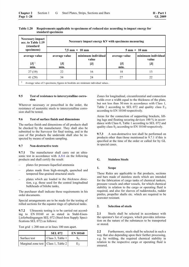
8/10/2019 Casting Material for Shipyards Etc
http://slidepdf.com/reader/full/casting-material-for-shipyards-etc 32/150
Table 1.20 Requirements applicable to specimens of reduced size according to impact energy forstandard specimens
Necessary impact energy KV with specimens measuring Necessary impact
acc. to Table 1.19
(standardspecimens) 7,5 mm 10 mm 5 mm 10 mm
average value
[J] 1
min.
average value
[J]
min.
minimum individual
value
[J]
average value
[J]
min.
minimum individual
value
[J]
27 (19) 22 16 18 13
41 (29) 34 24 27 22
1 Average value of 3 specimens; figures in booklets are minimum individual values..
9.5 Test of resistance to intercrystalline corro-sion
Wherever necessary or prescribed in the order, theresistance of austenitic steels to intercrystalline corro-sion shall be tested.
9.6 Test of surface finish and dimensions
The surface finish and dimensions of all products shall be checked by the manufacturer. They shall also besubmitted to the Surveyor for final testing, and in thecase of flat products the underside shall also be in-spected by means of random sampling.
9.7 Non-destructive tests
9.7.1 The manufacturer shall carry out an ultra-sonic test in accordance with A.8.6 on the following
products and shall certify the result:
– plates for pressure-liquefied ammonia
– plates made from high-strength, quenched andtempered fine-grained structural steels
– plates which are loaded in the thickness direc-tion, e.g. those used for the central longitudinal
bulkheads of bilobe tanks,The purchaser shall indicate these requirements in hisorder documents.
Special arrangements are to be made for the testing ofrolled sections for the equator rings of spherical tanks.
9.7.2 Ultrasonic testing is to be carried out accord-ing to EN 10160 or as stated in Stahl-Eisen-Lieferbedingungen SEL 072 (Steel-Iron Supply Speci-fications SEL 072) as follows:
Test grid ≤ 200 mm or in lines 100 mm apart.
SEL 072 EN 10160Surface test Class 3, Table 1 S1
Marginal zone test Class 1, Table 2 E3
Zones for longitudinal, circumferential and connection
welds over a width equal to the thickness of the plate,
but not less than 50 mm in accordance with Class 1,
Table 2 according to SEL 072 and quality class E3 according to EN 10160 respectively.
Areas for the connection of supporting brackets, lift-ing lugs and floating securing devices 100 % in accor-dance with Class 0, Table 1 according to SEL 072 andquality class S3 according to EN 10160 respectively.
9.7.3 A non-destructive test shall be performed on products other than those mentioned in 9.7.1 if this is
specified at the time of the order or called for by GLin special cases.
G. Stainless Steels
1. Scope
These Rules are applicable to flat products, sectionsand bars made of stainless steels which are intendedfor the fabrication of cargo tanks of chemical tankers,
pressure vessels and other vessels, for which chemical
stability in relation to the cargo or operating fluid isrequired, and also for sleeves of rudderstocks, rudder
pintles, propeller shafts etc. which are required to beseawater resistant.
2. Selection of steels
2.1 Steels shall be selected in accordance withthe operator's list of cargoes, which provides informa-tion on the nature of the substances to be transportedor stored.
2.2 Furthermore, steels shall be selected in such a
way that also depending upon their further processing,e.g. by welding, the required chemical stability inrelation to the respective cargo or operating fluid isensured.
Chapter 2Page 1–28
Section 1 Steel Plates, Strips, Sections and Bars II - Part 1GL 2009
G
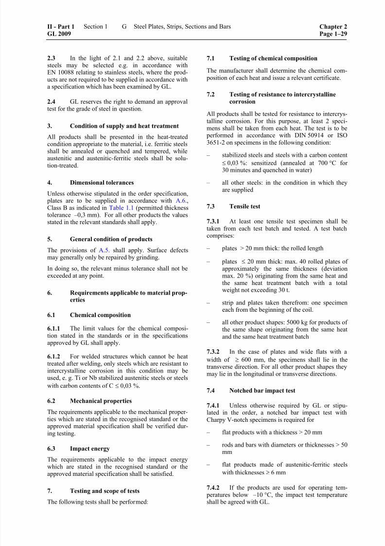
8/10/2019 Casting Material for Shipyards Etc
http://slidepdf.com/reader/full/casting-material-for-shipyards-etc 33/150
2.3 In the light of 2.1 and 2.2 above, suitablesteels may be selected e.g. in accordance withEN 10088 relating to stainless steels, where the prod-ucts are not required to be supplied in accordance witha specification which has been examined by GL.
2.4 GL reserves the right to demand an approvaltest for the grade of steel in question.
3. Condition of supply and heat treatment
All products shall be presented in the heat-treatedcondition appropriate to the material, i.e. ferritic steelsshall be annealed or quenched and tempered, whileaustenitic and austenitic-ferritic steels shall be solu-tion-treated.
4. Dimensional tolerances
Unless otherwise stipulated in the order specification, plates are to be supplied in accordance with A.6., Class B as indicated in Table 1.1 (permitted thicknesstolerance –0,3 mm). For all other products the valuesstated in the relevant standards shall apply.
5. General condition of products
The provisions of A.5. shall apply. Surface defectsmay generally only be repaired by grinding.
In doing so, the relevant minus tolerance shall not beexceeded at any point.
6. Requirements applicable to material prop-erties
6.1 Chemical composition
6.1.1 The limit values for the chemical composi-tion stated in the standards or in the specificationsapproved by GL shall apply.
6.1.2 For welded structures which cannot be heattreated after welding, only steels which are resistant tointercrystalline corrosion in this condition may beused, e. g. Ti or Nb stabilized austenitic steels or steels
with carbon contents of C ≤ 0,03 %.
6.2 Mechanical properties
The requirements applicable to the mechanical proper-ties which are stated in the recognised standard or theapproved material specification shall be verified dur-ing testing.
6.3 Impact energy
The requirements applicable to the impact energywhich are stated in the recognised standard or theapproved material specification shall be satisfied.
7. Testing and scope of tests
The following tests shall be performed:
7.1 Testing of chemical composition
The manufacturer shall determine the chemical com- position of each heat and issue a relevant certificate.
7.2 Testing of resistance to intercrystallinecorrosion
All products shall be tested for resistance to intercrys-talline corrosion. For this purpose, at least 2 speci-mens shall be taken from each heat. The test is to be
performed in accordance with DIN 50914 or ISO3651-2 on specimens in the following condition:
– stabilized steels and steels with a carbon content
≤ 0,03 %: sensitized (annealed at 700 °C for30 minutes and quenched in water)
– all other steels: in the condition in which they
are supplied
7.3 Tensile test
7.3.1 At least one tensile test specimen shall betaken from each test batch and tested. A test batchcomprises:
– plates > 20 mm thick: the rolled length
– plates ≤ 20 mm thick: max. 40 rolled plates ofapproximately the same thickness (deviationmax. 20 %) originating from the same heat andthe same heat treatment batch with a totalweight not exceeding 30 t.
– strip and plates taken therefrom: one specimeneach from the beginning of the coil.
– all other product shapes: 5000 kg for products ofthe same shape originating from the same heatand the same heat treatment batch
7.3.2 In the case of plates and wide flats with a
width of ≥ 600 mm, the specimens shall lie in thetransverse direction. For all other product shapes theymay lie in the longitudinal or transverse directions.
7.4 Notched bar impact test
7.4.1 Unless otherwise required by GL or stipu-lated in the order, a notched bar impact test withCharpy V-notch specimens is required for
– flat products with a thickness > 20 mm
– rods and bars with diameters or thicknesses > 50mm
– flat products made of austenitic-ferritic steels
with thicknesses ≥ 6 mm
7.4.2 If the products are used for operating tem- peratures below –10 °C, the impact test temperatureshall be agreed with GL.
II - Part 1GL 2009
Section 1 Steel Plates, Strips, Sections and Bars Chapter 2Page 1–29
G

8/10/2019 Casting Material for Shipyards Etc
http://slidepdf.com/reader/full/casting-material-for-shipyards-etc 34/150
7.5 Testing of surface finish and dimensions
The surface finish and dimensions of all products shall be checked by the manufacturer. The products shallalso be submitted to the Surveyor for final testing. Inthe case of flat products, the underside shall also beinspected as far as possible.
7.6 Testing for use of correct material
The manufacturer shall test his products before deliv-ery by appropriate methods as to whether the correctmaterial has been used and shall confirm this in theacceptance test certificate.
7.7 Other tests
If there are special requirements regarding resistanceto pitting or crevice corrosion, appropriate corrosiontests shall be performed, e.g. to ASTM-G48. Thescope of these tests will be determined by GL fromcase to case.
H. Clad Plates
1. Scope
These Rules are applicable to steel plates clad withcladding materials made of stainless steels and in-tended for the manufacture of containers and tanks,e. g. for chemical tankers. It may be agreed to applythese rules to plate clad with other materials, e. g.aluminium or copper-nickel alloys.
2. Suitability of cladding process
The manufacturer shall demonstrate by means of aninitial test of product suitability that the clad productssatisfy the requirements stated in 8. and the required
properties of the base material are preserved aftercladding.
3. Suitable materials
Steels conforming to B., C. and E. shall be used as base materials. The stainless steels specified in G. andother materials approved by GL for the purpose may
be used as cladding materials.
4. Method of manufacture and condition of
supply
4.1 Cladding may be performed by rolling orexplosive cladding or by a combination of the twomethods.
4.2 Plates clad with austenitic materials shall
normally be supplied in the as rolled condition. Whereheat treatment is required in special cases, this is gov-erned by the base material. However, the treatmentshall not impair either the chemical stability or the
bonding of the cladding material. The type of heattreatment shall be notified to GL.
5. Dimensions and tolerances
5.1 The nominal thickness of the cladding mate-rial shall be at least 2 mm. Where no closer thicknesstolerances are specified in the order, the minus toler-ances for the thickness shall be as shown in Table1.21.
Table 1.21 Minus tolerances in relation to the
thickness of the cladding material
Nominal thickness
[mm]
Minus tolerance
[mm]
≥ 2,0 < 2,5≥ 2,5 < 3
≥ 3,0 < 3,5
≥ 3,5 < 4,0
≥ 4,0
– 0,20 – 0,25
– 0,35
– 0,45
– 0,50
5.2 The tolerances for the base materials shall begoverned by the requirements for the respective steelgrades and product shapes.
6. Surface finish
6.1 The cladding materials shall have a smoothsurface consistent with their purpose. The surfaceshall be free from scale, impurities, annealing colourand such defects as may impair the manufacturing
processes applied to the material, its application or itschemical stability. The surface finish of the base mate-rial shall comply with A.5.
6.2 On the cladding material, the total surfacearea of all defects, with the exception of shallow de-fects as per 7.1, shall not exceed 20 % of the surfacearea of the cladding.
7. Repair of defects
7.1 Shallow defects in the cladding material, e.g.impressions, grooves and scratches, shall be removed
by grinding within the tolerance specified in 5.
7.2 In general points where bonding has not
occurred up to an area of 50 cm2 may be tolerated,except where the purchaser requires that certain areasof the plate be repaired.
7.3 Deep defects in the cladding material which
cannot be removed by grinding and lack of bonding inexcess of 50 cm2 may be repaired by welding pro-vided that the defects are isolated and separated from
each other, do not exceed 1200 cm2 in area and do not
Chapter 2Page 1–30
Section 1 Steel Plates, Strips, Sections and Bars II - Part 1GL 2009
H

8/10/2019 Casting Material for Shipyards Etc
http://slidepdf.com/reader/full/casting-material-for-shipyards-etc 35/150
total more than 5 % of the clad surface. Welding shall be subject to the following Rules:
7.3.1 All welds shall be made by qualified weldersusing a technique approved by GL.
7.3.2 The welds shall be free from cracks, lack offusion, undercuts, slag and other defects liable to im-
pair the characteristics of the cladding.
7.3.3 After welding, the repaired defect shall beground flush with the plate. Welding shall be followed
by heat treatment if this was specified by the proce-dure approval test or if called for in the order.
7.3.4 After final machining, the plates shall besubmitted to the Surveyor for final testing, and a suit-able non-destructive test technique, e.g. dye penetrantinspection, shall be used to prove that the repairs arefree from defects.
7.3.5 For each repair weld the manufacturer shallgive the Surveyor a report stating the dimensions andlocation of the defects, the details of the welding tech-nique used, the nature of any heat treatment appliedand the results of the test.
8. Requirements applicable to the material
The clad steels shall satisfy the following require-ments.
8.1 Elongation
In the case of clad steels where the elongation of thecladding material is less than that of the base material,the cladding material shall attain an elongation A5 of
at least 12 % in a tensile test after the base metal has been removed by machining.
8.2 Shear strength
The bond between the base and cladding materialsshall be adequate to ensure that the cladding materialcannot break away from the base material when
proper manufacturing processes or service loads areapplied. In the case of cladding materials with a ten-
sile strength of < 280 N/mm2, the shear strength shall be at least 50 % of the minimum tensile strength of thecladding material and for all other cladding materialsit shall be not less than 140 N/mm2, irrespective of thedirection of testing, unless otherwise agreed in theorder.
8.3 Bonding
The proportion of bonded surface shall be at least95 %, and the area of isolated points where bonding
has not occurred shall not exceed 50 cm². For clad
steels which are severely stressed during processing,e.g. in the manufacture of dished ends, or while in use,e.g. in tubesheets, it may be necessary for the pur-chaser to impose more stringent requirements.
8.4 Mechanical properties
When subjected to the tensile test, the clad plate shallsatisfy at least the following requirements:
G G A A pl pl
S S
S
σ ⋅ + σ ⋅
σ =
σ = specified minimum value of tensile strengthor yield strength or 0,2 % proof stress[N/mm2]
S = nominal thickness [mm]
Indices:
G = base material
A = cladding material
pl = clad steel
If the tensile test gives a lower value than that calcu-lated by the formula, the requirements applicable tothe base material may be verified by means of speci-mens from which the cladding material has been re-moved by machining.
The elongation specified for the base material con-cerned shall be verified by tests performed on cladspecimens.
8.5 Technological properties
When subjected to the side bend test, the clad plateshall be capable of being bent through 180° over amandrel with a diameter equal to four times the thick-ness of the specimen without separation of the clad-ding material or formation of incipient cracks.
Larger bending mandrel diameters may be agreed forother cladding materials, e.g. aluminium.
8.6 Impact energy
The requirements applicable to the base material shall be capable of being satisfied after cladding has beencarried out.
8.7 Resistance to intercrystalline corrosion
For austenitic or austenitic-ferritic cladding materials,the requirements applicable to the relevant grade ofsteel shall be satisfied.
9. Testing
The scope of the tests and the number and location ofthe test specimens are determined by the base mate-rial. The following tests are to be performed.
9.1 Test of chemical compositionThe manufacturer shall determine the chemical com-
position of each heat of base and cladding materialand shall issue a relevant certificate.
II - Part 1GL 2009
Section 1 Steel Plates, Strips, Sections and Bars Chapter 2Page 1–31
H

8/10/2019 Casting Material for Shipyards Etc
http://slidepdf.com/reader/full/casting-material-for-shipyards-etc 36/150
9.2 Test of resistance to intercrystalline corro-sion
In the case of austenitic and austenitic-ferritic claddingmaterials, the resistance to intercrystalline corrosionshall be verified for each test batch. For this purpose,
those plates may be grouped together into a test batchwhich have been clad in the same manufacturing cyclewith cladding materials originating from the sameheat. Under test, the clad side shall be subjected totensile stress.
9.3 Tensile test
The tensile test shall be performed on a transversespecimen from each test batch. Unless otherwiseagreed, the cladding material shall be left on the testspecimen. The gauge marks shall be applied to the
base material side.
9.4 Shear test
From each test batch a specimen shall be taken withits axis transverse to the rolling direction and this shall
be subjected to the shear test.
The test shall be performed in accordance with a rec-ognized standard, e.g. DIN 50162. The dimensions ofthe test specimen and the test arrangement are shownin Figure 1.2.
25
2 0
4 ,
5
6 5
10Shear test specimen
Claddingmaterial
Guideblocks
P
Fig. 1.2 Shear test
9.5 Side bend test
From each test batch a specimen shall be taken withits axis transverse to the rolling direction and this shall
be subjected to the side bend test. The dimensions ofthe test specimen and the test arrangement are shownin Figure 1.3. Where the product thickness exceeds80 mm, the specimens may be reduced to 80 mm bymachining the base material side.
9.6 Notched bar impact test
The notched bar impact test shall be performed in
cases where it is specified for the base material. Thenumber of specimens, their orientation and the testtemperature are subject to the same conditions asapply to the base material.
Fig. 1.3 Side bend test
9.7 Test of surface finish and dimensions
The surface finish and dimensions of all plates shall bechecked by the manufacturer and the thickness of thecladding shall be measured at the edges and in themiddle of the plate. All plates shall be submitted to theSurveyor for final testing and verification of the di-mensions.
9.8 Non-destructive testing
To ascertain the quality of the bond between the baseand cladding materials, the manufacturer shall carryout 100 % ultrasonic testing of the surfaces and edgesof all plates.
10. Marking
All plates are to be marked as follows:
– manufacturer's mark
– abbreviated steel grade designation or materialnumber of base and cladding material
– heat numbers of base and cladding material
– thickness of base and cladding material
– specimen no.
I. Steels with Through Thickness Properties
1. Scope
These Rules are supplementary to all Rules applyingto plates, strips, wide flats and shapes made of fine-grained structural steels for which enhanced deforma-
tion properties in the direction of product thickness arerequired. They apply to products with thicknessesgreater than or equal 15 mm. For smaller thicknessesthese Rules may be applied at discretion of GL.
Chapter 2Page 1–32
Section 1 Steel Plates, Strips, Sections and Bars II - Part 1GL 2009
I

8/10/2019 Casting Material for Shipyards Etc
http://slidepdf.com/reader/full/casting-material-for-shipyards-etc 37/150
2. Requirements
2.1 Reduction in area
The average value of the reduction in area measuredon 3 tensile test specimens (Z specimens) lying in thedirection of the product thickness shall be at least25 % for the grade Z25, including one test resultwhich may be lower than 25 % but not less than 20 %.
For the grade Z35 the reduction in area has to be atleast 35 %, including one test result which may belower than 35 % but not less than 25 %.
2.2 Freedom from defects
All products shall be free from defects liable to impairthe required characteristics in the thickness direction,e.g. laminations, major non-metallic inclusions, flakesand segregations.
In addition, when subjected to ultrasonic testing flat products shall satisfy the Class 2 test requirements laiddown in Stahl-Eisen-Lieferbedingung 072 (Iron andSteel Supply Conditions 072) or Class S2/E3 testrequirements according to EN 10160. For sectionsClass 1.2/23 test requirements according to EN 10306apply.
Note
Iron and Steel Supply Conditions 072 specify the fol-lowing Class 2 test requirements for the general ultra-
sonic test:
Minimum significant flaw size: 0,5 cm2
Maximum permissible flaw size: 1,0 cm2
Permissible incidence of flawsin relation to area:
locally: up to 30 m2
in relation to total plate area: up to 15/m2
Maximum permissible length of significant flaws: parallel to edge (edge testing): 4 cm
Permissible incidence of flaws
(edge testing): up to 5/m
2.3 Chemical composition
In addition to the requirements of the respective steelspecification the sulphur content determined by heatanalysis may not exceed 0,008 %.
3. Testing and scope of tests
The following tests shall be performed in addition tothe tests prescribed for the product in question.
3.1 Tensile testing of Z specimens
3.1.1 The test shall be performed on at least 3 ten-sile test specimens taken from each unit testing quan-tity with their longitudinal axes perpendicular to the
surface of the product (Z specimens). The unit testingquantities shall be taken from Table 1.22 and consistof products of the same heat, same thickness and sameheat treatment.
Table 1.22 Unit testing quantities
Sulphur contentProduct
S > 0,005 % S 0,005 %
Plates rolled length
Wide flats up to
and including 25
mm thickness
10 t
Wide flats
exceeding 25
mm thickness
20 t
50 t
3.1.2 In the case of flat products, the specimensshall be taken from one end in the longitudinal axis ofthe product, see Fig. 1.4. In both cases the centre ofthe product shall fall within the test length. In the caseof sections, the specimens shall be taken from one endof the product at a distance of 1/3 of the flange widthfrom the outside edge of the flange, see Fig. 1.4.
Fig. 1.4 Sampling of Z specimens
3.1.3 Tensile test with extension pieces
Steel extension pieces, e.g. studs, shall be welded tothe two surfaces of the sample which lie perpendicular
to the thickness direction of the steel product; see Fig.1.5. Examples of permissible welding processes arestud or friction welding.
Fig. 1.5 Specimen blank, consisting of test piece
and welded-on extension pieces
II - Part 1GL 2009
Section 1 Steel Plates, Strips, Sections and Bars Chapter 2Page 1–33
I
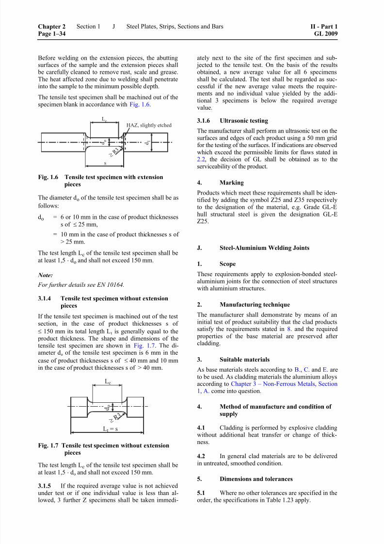
8/10/2019 Casting Material for Shipyards Etc
http://slidepdf.com/reader/full/casting-material-for-shipyards-etc 38/150
Before welding on the extension pieces, the abuttingsurfaces of the sample and the extension pieces shall
be carefully cleaned to remove rust, scale and grease.The heat affected zone due to welding shall penetrateinto the sample to the minimum possible depth.
The tensile test specimen shall be machined out of thespecimen blank in accordance with Fig. 1.6.
Fig. 1.6 Tensile test specimen with extensionpieces
The diameter do of the tensile test specimen shall be as
follows:
do = 6 or 10 mm in the case of product thicknesses
s of ≤ 25 mm,
= 10 mm in the case of product thicknesses s of
> 25 mm.
The test length Lc of the tensile test specimen shall be
at least 1,5 ⋅ do and shall not exceed 150 mm.
Note:
For further details see EN 10164.
3.1.4 Tensile test specimen without extensionpieces
If the tensile test specimen is machined out of the testsection, in the case of product thicknesses s of
≤ 150 mm its total length Lt is generally equal to the product thickness. The shape and dimensions of thetensile test specimen are shown in Fig. 1.7. The di-ameter do of the tensile test specimen is 6 mm in the
case of product thicknesses s of ≤ 40 mm and 10 mmin the case of product thicknesses s of > 40 mm.
Fig. 1.7 Tensile test specimen without extensionpieces
The test length Lc of the tensile test specimen shall beat least 1,5 ⋅ do and shall not exceed 150 mm.
3.1.5 If the required average value is not achievedunder test or if one individual value is less than al-lowed, 3 further Z specimens shall be taken immedi-
ately next to the site of the first specimen and sub- jected to the tensile test. On the basis of the resultsobtained, a new average value for all 6 specimensshall be calculated. The test shall be regarded as suc-cessful if the new average value meets the require-
ments and no individual value yielded by the addi-tional 3 specimens is below the required averagevalue.
3.1.6 Ultrasonic testing
The manufacturer shall perform an ultrasonic test on thesurfaces and edges of each product using a 50 mm gridfor the testing of the surfaces. If indications are observedwhich exceed the permissible limits for flaws stated in2.2, the decision of GL shall be obtained as to theserviceability of the product.
4. Marking
Products which meet these requirements shall be iden-tified by adding the symbol Z25 and Z35 respectivelyto the designation of the material, e.g. Grade GL-Ehull structural steel is given the designation GL-EZ25.
J. Steel-Aluminium Welding Joints
1. Scope
These requirements apply to explosion-bonded steel-aluminium joints for the connection of steel structureswith aluminium structures.
2. Manufacturing technique
The manufacturer shall demonstrate by means of aninitial test of product suitability that the clad productssatisfy the requirements stated in 8. and the required
properties of the base material are preserved aftercladding.
3. Suitable materials
As base materials steels according to B., C. and E. areto be used. As cladding materials the aluminium alloysaccording to Chapter 3 – Non-Ferrous Metals, Section1, A. come into question.
4. Method of manufacture and condition of
supply
4.1 Cladding is performed by explosive claddingwithout additional heat transfer or change of thick-ness.
4.2 In general clad materials are to be deliveredin untreated, smoothed condition.
5. Dimensions and tolerances
5.1 Where no other tolerances are specified in theorder, the specifications in Table 1.23 apply.
Chapter 2Page 1–34
Section 1 Steel Plates, Strips, Sections and Bars II - Part 1GL 2009
J

8/10/2019 Casting Material for Shipyards Etc
http://slidepdf.com/reader/full/casting-material-for-shipyards-etc 39/150
Table 1.23 Permissible tolerances
Tolerance [mm]Product
lower upper
Thickness all – 2 + 1
Length all 0 + 10
plates 0 + 10
< 25 mm width – 1,5 + 1,5Widthrods 1
> 25 mm width – 2 + 2
< 500 mm diameter 0 + 2Diameter
circular
blanks > 500 mm diameter 0 + 5
plates
(difference between the diagonals)max. 10
Rectangularityrods 1
(perpendicular projection of a longitudinal edge or a
transverse edge)
max. 1,5
≥ 1 m length max. 5Evenness (aluminium side)
< 1 m length max. 0,5 % of length
Straightness of
longitudinal edgesrods 1 max. 5
1 Rods are contrary to plates flat products of a width ≤ 300 mm.
5.2 The tolerances for the base materials shall begoverned by the requirements for the respective steelgrades and product shapes.
6. Surface finish
The surface finish shall meet the respective require-ments for the base materials.
7. Requirements applicable to the material
7.1 Shear strength
The bond between the base and cladding materialsshall be adequate to ensure that the cladding materialcannot break away from the base material when
proper manufacturing processes and service conditionare applied. The shear strength shall be at least 60
N/mm² irrespective of the direction of testing, unlesshigher values have been agreed in the order.
7.2 Bonding
The proportion of bonded surface shall be at least 99%
and the area of isolated points where bonding has not
occurred shall not exceed 650 mm2. Rods and circular
blanks of 300 mm or less width and diameter respec-
tively shall not show indications to be registered. Ifrods or circular blanks are cut from the original plate,
the distance to indications to be registered shall be atleast 20 mm.
7.3 Tensile test
The tensile strength of a clad plate subjected to a ten-
sile test shall be at least 60 N/mm2, unless highervalues have been agreed in the order.
7.4 Technological properties
When subjected to the side bend test, the clad plateshall be capable of being bent through 90° over amandrel with a diameter of 6 times the thickness ofthe specimen, without separation of the cladding mate-rial or formation of incipient cracks.
8. Testing
8.1 Tensile test
From each end of the original plate 2 specimens withtheir longitudinal axis perpendicular to the productsurface shall be taken and tested. Specimen shape is to
be chosen according to I. One specimen of each end isto be heated to 300 °C before testing.
8.2 Shear test
From each test batch a specimen shall be taken with
its axis transverse to the rolling direction and this shall be subjected to the shear test.
The test shall be performed in accordance with a rec-ognized standard, e.g. DIN 50162. The dimensions of
II - Part 1GL 2009
Section 1 Steel Plates, Strips, Sections and Bars Chapter 2Page 1–35
J

8/10/2019 Casting Material for Shipyards Etc
http://slidepdf.com/reader/full/casting-material-for-shipyards-etc 40/150
the test specimen and the test arrangement are shownin Fig. 1.2.
One specimen of each end is to be heated to 300 °C before testing.
8.3 Side bend test
If specially agreed in the order, one specimen of eachoriginal plate is to be taken and tested. Dimensions ofthe test specimen and test arrangement are shown inFig. 1.3. Where the product thickness exceeds 80 mm,the specimens may be reduced to 80 mm by machin-ing the base material side.
8.4 Test of surface finish and dimensions
The surface finish and dimensions of all plates shall bechecked by the manufacturer and the thickness of thecladding shall be measured at the edges and in the
middle of the plate. All plates shall be submitted to theSurveyor for final testing and verification of the di-mensions.
8.5 Non-destructive testing
To ascertain the quality of the bond between the baseand cladding materials, the manufacturer shall carryout 100 % ultrasonic testing of the surfaces and edges
of all plates.
9. Marking
All plates are to be marked on the base material sideas follows:
– manufacturer’s mark
– short name of steel grade designation or materialnumber of base and cladding material
– heat numbers of base and cladding material
– thickness of base and cladding material,
– specimen no.
Chapter 2Page 1–36
Section 1 Steel Plates, Strips, Sections and Bars II - Part 1GL 2009
J
8/10/2019 Casting Material for Shipyards Etc
http://slidepdf.com/reader/full/casting-material-for-shipyards-etc 41/150
Section 2
Steel Pipes
A. General Rules
1. Scope
1.1 The general Rules contained in A. to be ob-served in the manufacture of seamless and weldedsteel pipes apply in conjunction with the followingindividual requirements B. to E.
The scope of these Rules embraces all pipes used in
the construction of steam boilers, pressure vessels andequipment as well as for pipelines, accumulators and
pressure cylinders.
As regards steel pipes for structural applications,Section 1, B., C., D. and G. shall apply respectively.
Pipes which are individually manufactured andwelded, such as masts, crane posts, pressure vesselshells etc. shall also comply with Part 3 –Welding.
1.2 Pipes conforming to national or internationalstandards or to manufacturers' specifications may beapproved provided that their properties are equivalent
to the properties stipulated in these Rules or wherespecial approval has been granted for their use. Refer-ences to standardized materials whose use is permittedare contained in the following individual Rules.
1.3 Pipes conforming to these Rules may bedesignated either in accordance with the relevant stan-dards or with the symbols shown in the Tables. In thelatter case, pipes made of carbon and carbon-manganese steels shall be identified by their minimumtensile strength and, where applicable, by the addedletter W denoting high-temperature steel or T denotingsteel tough at sub-zero temperatures, while alloy
pipes, with the exception of the austenitic grades, shall be identified by the symbols denoting their alloy con-tent.
2. Requirements to be met by pipe manufac-
turers
2.1 Pipe manufacturers wishing to supply pipesin accordance with these Rules shall be approved byGL. Such approval is conditional upon their fulfillingthe requirements stated in Chapter 1 – Principles andTest Procedures, Section 1, C. and demonstrating thisto GL prior to the commencement of supplies.
2.2 In addition, where welded pipes are manufac-tured, the characteristics and the required quality of
the welded seam shall be subject to preliminary proofin the form of a procedure approval test the extent ofwhich shall be determined by GL on a case to case
basis.
GL reserve the right to demand that a test of suitability be carried out in the case of seamless pipes also wherethese have to meet special requirements, e.g. in respectof their impact energy at low temperatures or theirhigh-temperature strength characteristics.
3. Manufacturing process, condition of supply
3.1 Pipe steels shall be made by basic oxygensteelmaking processes, in an electric furnace or byother methods approved by GL. Unless otherwisespecified, the steels shall be killed.
3.2 Seamless pipes may be manufactured by hotor cold rolling (cold pilger rolling), by hot pressing or
by hot or cold drawing.
3.3 Welded ferritic steel pipes may be manufac-
tured by electrical induction or resistance pressurewelding or by fusion welding of strip or plates, andmay be subjected to hot or cold reduction. For austen-itic steels tough at sub-zero temperatures and austen-itic stainless steels, only fusion welding processes may
be used. The manufacturing process and the testingshall ensure a weld quality factor of v = 1,0.
3.4 All pipes shall be supplied in a properly heat-treated condition over their whole length according tothe requirements of B. to E.
4. General characteristics of pipes
4.1 Pipes may not display any cracks. Defectsliable to have more than an insignificant effect on theuse or further treatment of the pipes may be removed
by grinding within the minimum permissible wallthickness. Repair welds are not allowed. This Rulemay be waived in the case of the seams of fusion-welded pipes.
4.2 Pipes shall have a smooth inside and outsidesurface consistent with the method of manufacture.Minor depressions or shallow longitudinal groovesdue to the manufacturing process may be tolerated
provided that they do not impair the serviceability ofthe pipes and the wall thickness remains within the
permitted tolerances.
II - Part 1GL 2009
Section 2 Steel Pipes Chapter 2Page 2–1
A

8/10/2019 Casting Material for Shipyards Etc
http://slidepdf.com/reader/full/casting-material-for-shipyards-etc 42/150

8/10/2019 Casting Material for Shipyards Etc
http://slidepdf.com/reader/full/casting-material-for-shipyards-etc 43/150
Table 2.1 Types of ring test
Nominal wall thickness t
[mm]
Outside diameter of pipe
[mm]
t 2 2 t 16 16 t 40
≤ 21,3 ring flattening test 1, 3 ring flattening test 1, 3 —
> 21,3 ≤ 146 ring flattening test 1, 3 ring expanding test 1, 3 ring flattening
> 146 — ring tensile test 2 ring tensile test 2
1 The drift expanding test may also be applied to welded pipes.
2 Instead of the ring tensile test, the flattening test is applied to pipes with bores of 100 mm.
3 The drift expanding test is applied to seamless and welded pipes in compliance with EN 10305-1 and -2 respectively.
8.5 Technological tests
8.5.1 The pipes selected for testing shall be sub- jected to one of the ring tests specified in Table 2.1 provided that the wall thickness of the pipe does notexceed 40 mm. For the performance of the test, seeChapter 1 – Principles and Test Procedures, Section 2,F.
The number of test specimens depends on the applica-tion of the pipes and is stipulated in the requirementsof B. to E.
8.5.2 In the ring flattening test, the prescribed dis-tance between the plates H is calculated by applyingthe following formula:
(1 C) aH
C a / D
+=
+
H = distance between the platens [mm]
a = nominal wall thickness [mm]
D = outside diameter of pipe [mm]
C = constant determined by the steel grade (seethe provisions relating to technological testsaccording to B. to E.).
Where ring specimens of welded pipes are tested, theweld shall be set at 90° to the direction of the com-
pressive load.
8.5.3 In the ring expanding test, the change in thediameter of the specimen expanded to the point offracture shall at least equal the percentages shown inTable 2.2, depending on the material.
8.5.4 When the ring tensile test is applied tospecimens of welded pipes, the weld shall be set at90° to the direction of the tensile load.
Table 2.2 Diameter change in the ring expand-ing test
Minimum expansion [%] for ID/OD
ratios ofPipe
material
≥ 0,9≥ 0,8
< 0,9
≥ 0,7
< 0,8
≥ 0,6
< 0,7
≥ 0,5
< 0,6≥ 0,5
C- andCMn-steels
8 10 12 20 25 30
Mo-, CrMo-and
Ni-steels
6 8 10 15 30 30
Austeniticsteels
30
8.5.5 In the drift expanding test applied to austen-itic steel pipes a 20 % expansion shall be achieved.Where pipes are made of other steels, the requirementsof the other relevant standards shall be achieved.
8.6 Test of surface finish and dimensions
The finish of the inside and outside surface of each
pipe shall be inspected by the manufacturer. The di-ameters and wall thicknesses shall also be measured.The pipes shall then be submitted to the Surveyor forfinal testing.
8.7 Non-destructive tests
8.7.1 The pipes shall be subjected to non-destructive tests of the extent specified in B. to E.Where tests of greater scope are prescribed in theorder or in the relevant standards or specifications,these requirements shall be complied with.
8.7.2 Other test specifications require special ap- proval by GL.
8.7.3 The test equipment used for the continuousinspection of pipes shall be regularly calibrated using
II - Part 1GL 2009
Section 2 Steel Pipes Chapter 2Page 2–3
A

8/10/2019 Casting Material for Shipyards Etc
http://slidepdf.com/reader/full/casting-material-for-shipyards-etc 44/150
pipes with artificial defects. The efficiency of theequipment shall be demonstrated to the Surveyor.
8.8 Tightness test
8.8.1 All pipes shall be tested for leaks by themanufacturer by applying the internal pressure test or,where GL has given its consent, by a suitable non-destructive testing method, e.g. eddy current or strayflux techniques.
8.8.2 The internal pressure test shall normally be performed at a standard hydraulic test pressure of 80 bar. Where pipes are intended for an operating pres-
sure of ≤ 25 bar, the test pressure may be reduced to astandard value of 50 bar. In the case of thin-walled
pipes with large outside diameters, the test pressureshall be limited so as to ensure that the yield strengthor 0,2 % proof stress of the pipe material at roomtemperature is not exceeded. Where, in exceptionalcases, testing with water is not possible, another test-ing medium may be used after agreement with theSurveyor.
8.8.3 Where a non-destructive method of testing isto be used instead of the internal hydraulic pressuretest it shall be able to cover the whole circumferenceof the pipe. In addition, the method of testing shallconform to a recognized standard (e.g. EN 10246) orto an approved test specification. The efficiency of themethod shall be initially demonstrated to GL.
8.9 Retests in the event of failure of specimens
If the requirements are not met by specimens sub- jected to tensile, ring or notched bar impact tests or if,in the notched bar impact test, one individual valuefalls below 70 % of the stipulated average value, then,
before the unit testing quantity is rejected, the proce-dure for retests described in Chapter 1 – Principles andTest Procedures, Section 2, H. may be applied.
9. Marking of pipes
9.1 The manufacturer shall mark each pipe asfollows in at least one position about 300 mm from theend:
– short designation or material number of the steelgrade
– manufacturer's mark
– additionally, the heat number or a heat code
9.2 Markings shall be applied with punches.
Pipes with sensitive surfaces or small wall thicknesseswhich may be damaged by punches shall be marked
by another method, e.g. by coloured imprint, electricalengraving or rubber stamps.
10. Certificates
10.1 For each consignment the manufacturer shallfurnish the Surveyor with a certificate containing thefollowing details:
– purchaser and order number
– newbuilding and project number respectively,where known
– quantity, dimensions and weight of delivered pipes
– strength category or pipe grade
– steel grade or material specification
– method of pipe manufacture
– heat numbers
– chemical composition of the heat
– condition in which supplied or heat treatmentapplied
– marking
– results of material testing
10.2 The manufacturer shall also certify that allthe pipes have been successfully tightness tested and,where applicable, have successfully undergone a non-destructive test and a test of resistance to intercrystal-line corrosion.
10.3 If the steels of which the pipes are made arenot produced in the pipe works, a steelmaker's certifi-cate shall be handed to the Surveyor indicating thenumbers and analyses of the heats. The steelmakershall have been approved for the grades concerned. Incase of doubt, the Surveyor shall be given facilities forcarrying out a check.
10.4 Where, in exceptional cases, pipes are testedon the premises of a stockist, the latter shall keep aclear record of the origin of the pipes, which shall bearthe marking specified in 9. and, in the case of boilertubes, the stamp of the works inspector as well. In
addition, the Surveyor shall be furnished with a cer-tificate issued by the pipe manufacturer and containingthe following details:
– number, dimensions and weight of the pipessupplied
– steel grade or material specification
– method of pipe manufacture and condition inwhich supplied or method of heat treatment
– heat numbers and analyses
– confirmation that the tightness test and, where
specified, the non-destructive test and test of re-sistance to intercrystalline corrosion have beencarried out
– marking
Chapter 2Page 2–4
Section 2 Steel Pipes II - Part 1GL 2009
A

8/10/2019 Casting Material for Shipyards Etc
http://slidepdf.com/reader/full/casting-material-for-shipyards-etc 45/150
B. Pipes for General Purpose
1. Scope
1.1 These Rules are applicable to seamless andwelded pipes for use in pressure vessels, equipment,
pipelines and pressure cylinders. Pipes conforming tothese rules are intended for use at normal ambienttemperatures.
In general for these applications pipe grades accordingto Table 2.3. are to be used.
If the pipes are intended for the manufacture of hy-draulic cylinders exposed to low service temperatures,a minimum impact energy of 41 J is to be proven onlongitudinal ISO-V specimens, which may lead to theapplication of steels tough at sub-zero temperatures.
1.2 Pipes conforming to these Rules may be usedfor the cargo and processing equipment of gas tankers
provided that the relevant design temperatures are not below 0 °C.
2. Heat treatment
The pipes shall be in a proper heat-treated condition.This is generally to be achieved by normalizing.
Subsequent heat treatment need not be applied to hot-formed pipes if the hot forming operation ensures acorresponding structure of sufficient uniformity.
3. Requirements applicable to the material
3.1 Chemical composition
The chemical composition of the pipe steels shallconform to the data given in Table 2.4 or, where ap-
propriate, in the relevant standards or specifications.
3.2 Mechanical properties
The required values of tensile strength, yield strengthand elongation specified in Table 2.5 or, where appro-
priate, in the relevant standards or specifications shall be met under test at room temperature.
3.3 Technological properties
When subjected to the ring tests, the pipes shall dis- play a capacity for deformation which meets the re-quirements specified in A.8.5.
3.4 Impact energy
The pipes shall at least satisfy the impact energy re-quirements specified in Table 2.5.
4. Testing and scope of tests
The following tests are to be performed:
4.1 Test of chemical composition
The manufacturer shall determine the chemical com- position of each heat in accordance with A.8.1.
Table 2.3 Standardized pipe grades
Corresponding pipe grade toStrength category or
pipe grade to
Table 2.5
EN 10216-1 1
or
EN 10217-1 2
EN 10216-3 1
or
EN 10217-3 2
EN 10305-1 EN 10305-2
GL–R 360 P235TR2 E235+N E235+N
GL–R 410 P265TR2 P275NL1 E275+N
GL–R 490 P355N E355+N E355+N
1 seamless2 welded
Table 2.4 Chemical composition of unalloyed steel pipes
Chemical composition [%]Strength
category or
pipe grade Cmax. Simax. Mn max. Pmax. Smax. Altot.
GL–R 360 0,17 0,35 1,20
GL–R 410 0,21 0,35 1,40
GL–R 490 0,22 0,55 1,60
0,025 0,020 ≥ 0,020 1
1 This requirement does not apply if the steel contains a sufficient fraction of other nitrogen absorbing elements, which is to be specified.
II - Part 1GL 2009
Section 2 Steel Pipes Chapter 2Page 2–5
B
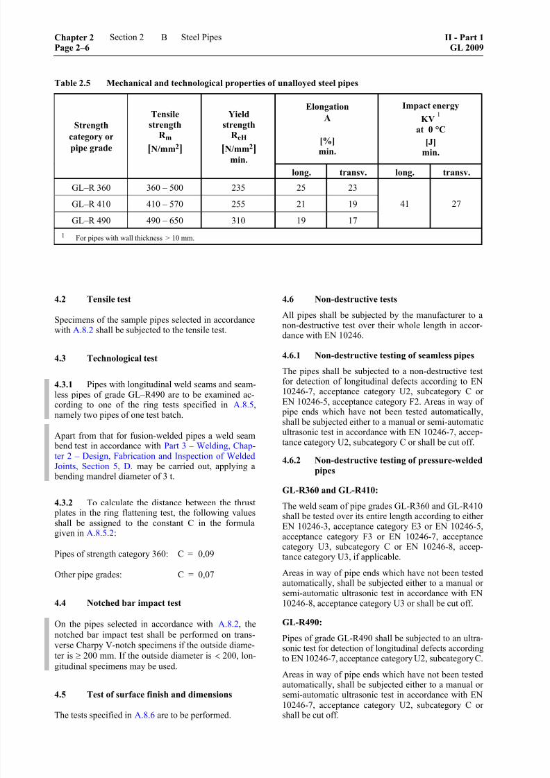
8/10/2019 Casting Material for Shipyards Etc
http://slidepdf.com/reader/full/casting-material-for-shipyards-etc 46/150
Table 2.5 Mechanical and technological properties of unalloyed steel pipes
Elongation
A
[%]
min.
Impact energy
KV1
at 0 °C
[J]
min.
Strength
category orpipe grade
Tensile
strength
R m
[N/mm2]
Yield
strength
R eH
[N/mm2]
min.
long. transv. long. transv.
GL–R 360 360 – 500 235 25 23
GL–R 410 410 – 570 255 21 19
GL–R 490 490 – 650 310 19 17
41 27
1 For pipes with wall thickness > 10 mm.
4.2 Tensile test
Specimens of the sample pipes selected in accordancewith A.8.2 shall be subjected to the tensile test.
4.3 Technological test
4.3.1 Pipes with longitudinal weld seams and seam-less pipes of grade GL–R490 are to be examined ac-
cording to one of the ring tests specified in A.8.5, namely two pipes of one test batch.
Apart from that for fusion-welded pipes a weld seam bend test in accordance with Part 3 – Welding, Chap-ter 2 – Design, Fabrication and Inspection of WeldedJoints, Section 5, D. may be carried out, applying a
bending mandrel diameter of 3 t.
4.3.2 To calculate the distance between the thrust plates in the ring flattening test, the following valuesshall be assigned to the constant C in the formulagiven in A.8.5.2:
Pipes of strength category 360: C = 0,09
Other pipe grades: C = 0,07
4.4 Notched bar impact test
On the pipes selected in accordance with A.8.2, the
notched bar impact test shall be performed on trans-verse Charpy V-notch specimens if the outside diame-
ter is ≥ 200 mm. If the outside diameter is < 200, lon-
gitudinal specimens may be used.
4.5 Test of surface finish and dimensions
The tests specified in A.8.6 are to be performed.
4.6 Non-destructive tests
All pipes shall be subjected by the manufacturer to anon-destructive test over their whole length in accor-dance with EN 10246.
4.6.1 Non-destructive testing of seamless pipes
The pipes shall be subjected to a non-destructive testfor detection of longitudinal defects according to EN10246-7, acceptance category U2, subcategory C orEN 10246-5, acceptance category F2. Areas in way of
pipe ends which have not been tested automatically,shall be subjected either to a manual or semi-automaticultrasonic test in accordance with EN 10246-7, accep-tance category U2, subcategory C or shall be cut off.
4.6.2 Non-destructive testing of pressure-welded
pipes
GL-R360 and GL-R410:
The weld seam of pipe grades GL-R360 and GL-R410shall be tested over its entire length according to eitherEN 10246-3, acceptance category E3 or EN 10246-5,acceptance category F3 or EN 10246-7, acceptance
category U3, subcategory C or EN 10246-8, accep-tance category U3, if applicable.
Areas in way of pipe ends which have not been testedautomatically, shall be subjected either to a manual orsemi-automatic ultrasonic test in accordance with EN10246-8, acceptance category U3 or shall be cut off.
GL-R490:
Pipes of grade GL-R490 shall be subjected to an ultra-sonic test for detection of longitudinal defects according
to EN 10246-7, acceptance category U2, subcategory C.
Areas in way of pipe ends which have not been tested
automatically, shall be subjected either to a manual orsemi-automatic ultrasonic test in accordance with EN10246-7, acceptance category U2, subcategory C orshall be cut off.
Chapter 2Page 2–6
Section 2 Steel Pipes II - Part 1GL 2009
B

8/10/2019 Casting Material for Shipyards Etc
http://slidepdf.com/reader/full/casting-material-for-shipyards-etc 47/150
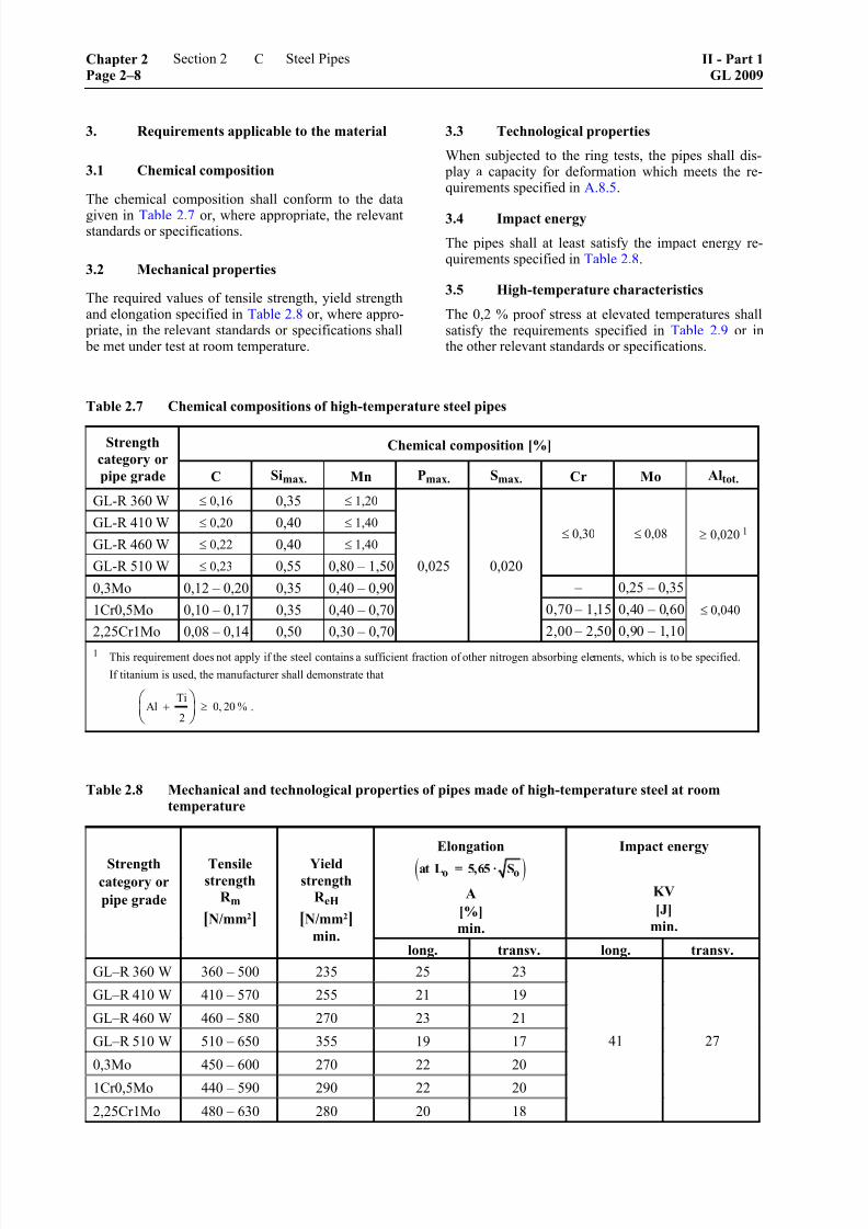
8/10/2019 Casting Material for Shipyards Etc
http://slidepdf.com/reader/full/casting-material-for-shipyards-etc 48/150

8/10/2019 Casting Material for Shipyards Etc
http://slidepdf.com/reader/full/casting-material-for-shipyards-etc 49/150
Table 2.9 Minimum values of yield strength R p0,2 at elevated temperatures
Steel gradeMinimum yield strength R p0,2 [N/mm2]
at a temperature [°C] of
Materialcode
Materialnumber 100 150 200 250 300 350 400 450 500
GL-R360W 1.0345 198 187 170 150 132 120 112 108 –
GL-R410W 1.0425 226 213 192 171 154 141 134 128 –
GL-R460W – – – 235 215 175 155 145 135 –
GL-R510W 1.0471 312 292 264 241 219 200 186 174 –
0,3Mo 1.5415 243 237 224 205 173 159 156 150 146
1Cr0,5Mo 1.7335 264 253 245 236 192 182 174 168 166
2,25Cr1Mo 1.7380 249 241 234 224 219 212 207 193 180
3.6 Dimensional tolerances for collectors
Seamless collector pipes and collectors with inside
diameters ≤ 600 mm are subject to the following di-mensional tolerances:
– on the inner or outer clear width: ± 1,0 % where
the outer clear width is ≤ 225 mm, or ± 1,5 %where the outer clear width is > 225 mm
– 0 % to + 25 % on the wall thickness
– the lateral curvature of square pipes shall be asshown in Fig. 2.1
Fig. 2.1 Tolerance on the lateral curvatureof square pipes
In square pipes, the inner corner radius r in relation tothe wall thickness s shall be at least:
sr 8 mm
3≥ ≥
4. Testing and scope of tests
The following tests are to be performed:
4.1 Test of chemical composition
The manufacturer shall determine the chemical com- position of each heat in accordance with A.8.1.
4.2 Tensile test
Specimens of the sample pipes selected in accordancewith A.8.2 shall be subjected to the tensile test.
4.3 Technological test
4.3.1 The pipes, namely two pipes of one test batch, shall undergo one of the ring tests specified inA., Table 2.1 as follows:
For fusion-welded pipes a weld seam bend test in
accordance with Part 3 – Welding, Chapter 2 – De-sign, Fabrication and Inspection of Welded Joints,Section 5, D. is to be carried out, applying a bendingmandrel diameter of 3 t.
4.3.2 To calculate the distance between the thrust plates in the ring flattening test, the following valuesshall be assigned to the constant C in the formulagiven in A.8.5.2:
Pipes of strength categories 360: C = 0,09
Other pipe grades: C = 0,07
4.4 Notched bar impact test
The test is to be carried out at room temperature on the
sample pipes selected in accordance with A.8.2, using
transverse Charpy V-notch specimens if the outside
diameter is ≥ 200 mm. If the outside diameter is < 200
mm, longitudinal specimens may be used.
4.5 High-temperature tensile test
Where stipulated in A.8.3 or in the purchase order, the0,2 % proof stress shall be determined by a high-temperature tensile test.
4.6 Test of surface finish and dimensions
The tests specified in A.8.6 are to be performed.
II - Part 1GL 2009
Section 2 Steel Pipes Chapter 2Page 2–9
C
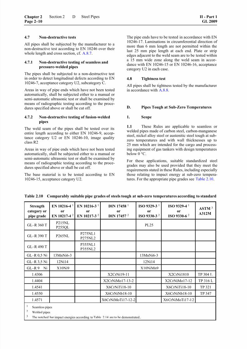
8/10/2019 Casting Material for Shipyards Etc
http://slidepdf.com/reader/full/casting-material-for-shipyards-etc 50/150
4.7 Non-destructive tests
All pipes shall be subjected by the manufacturer to anon-destructive test according to EN 10246 over theirwhole length and cross section, cf. A.8.7.
4.7.1 Non-destructive testing of seamless andpressure-welded pipes
The pipes shall be subjected to a non-destructive testin order to detect longitudinal defects according to EN10246-7, acceptance category U2, subcategory C.
Areas in way of pipe ends which have not been testedautomatically, shall be subjected either to a manual orsemi-automatic ultrasonic test or shall be examined bymeans of radiographic testing according to the proce-dures specified above or shall be cut off.
4.7.2 Non-destructive testing of fusion-welded
pipes
The weld seam of the pipes shall be tested over itsentire length according to either EN 10246-9, accep-tance category U2 or EN 10246-10, image qualityclass R2
Areas in way of pipe ends which have not been testedautomatically, shall be subjected either to a manual orsemi-automatic ultrasonic test or shall be examined bymeans of radiographic testing according to the proce-dures specified above or shall be cut off.
The base material is to be tested according to EN10246-15, acceptance category U2.
The pipe ends have to be tested in accordance with EN10246-17. Laminations in circumferential direction ofmore than 6 mm length are not permitted within thelast 25 mm pipe length at each end. Plate or stripedges adjacent to the weld seam are to be tested within
a 15 mm wide zone along the weld seam in accor-dance with EN 10246-15 or EN 10246-16, acceptancecategory U2 in each case.
4.8 Tightness test
All pipes shall be tightness tested by the manufacturerin accordance with A.8.8.
D. Pipes Tough at Sub-Zero Temperatures
1. Scope
1.1 These Rules are applicable to seamless orwelded pipes made of carbon steel, carbon-manganesesteel, nickel alloy steel or austenitic steel tough at sub-zero temperatures and with wall thicknesses up to25 mm which are intended for the cargo and process-ing equipment of gas tankers with design temperatures
below 0 °C.
For these applications, suitable standardized steel grades may also be used provided that they meet the
requirements stated in these Rules, including especially
those relating to impact energy at sub-zero tempera-tures. For the appropriate pipe grades see Table 2.10.
Table 2.10 Comparably suitable pipe grades of steels tough at sub-zero temperatures according to standard
Strength
category or
pipe grade
EN 10216-4 1
or
EN 10217-4 2
EN 10216-3 1
or
EN 10217-3 2
DIN 17458 1
or
DIN 17457 2
ISO 9329-3 1
or
ISO 9330-3 2
ISO 9329-4 1
or
ISO 9330-6 2
ASTM 3
A312M
GL–R 360 TP215NL
P255QLPL25
GL–R 390 T P265NLP275NL1
P275NL2
GL–R 490 T P355NL1P355NL2
GL–R 0,5 Ni 13MnNi6-3 13MnNi6-3
GL–R 3,5 Ni 12Ni14 12Ni14
GL–R 9 Ni X10Ni9 X10NiMn9
1.4306 X2CrNi19-11 X2CrNi1810 TP 304 L
1.4404 X2CrNiMo17-13-2 X2CrNiMo17-12 TP 316 L
1.4541 X6CrNiTi18-10 X6CrNiTi18-10 TP 321
1.4550 X6CrNiNb18-10 X6CrNiNb18-10 TP 347
1.4571 X6CrNiMoTi17-12-2 X6CrNiMoTi17-12
1 Seamless pipes
2 Welded pipes3 The notched bar impact energies according to Table 2.14 are to be demonstrated..
Chapter 2Page 2–10
Section 2 Steel Pipes II - Part 1GL 2009
D

8/10/2019 Casting Material for Shipyards Etc
http://slidepdf.com/reader/full/casting-material-for-shipyards-etc 51/150

8/10/2019 Casting Material for Shipyards Etc
http://slidepdf.com/reader/full/casting-material-for-shipyards-etc 52/150
Table 2.13 Chemical composition of steel pipes tough at sub-zero temperatures
Chemical composition [%] Strength
category or
pipe grade Cmax. Si Mn Pmax. Smax. Cr Ni Mo Other elements
GL–R 360 T 0,16 ≤ 0,40 0,40 – 1,20
GL–R 390 T 0,16 ≤ 0,40 0,50 – 1,50
GL–R 490 T 0,18 0,10 – 0,50 ≥ 0,90
0,025 0,020 ≤ 0,30 ≤ 0,3 ≤ 0,08 Almet ≥ 0,015 1, 2
GL–R 0,5 Ni 0,16 ≤ 0,50 0,85 – 1,70 0,025 0,015 ≤ 0,15 0,30 – 0,85 ≤ 0,10 Almet ≥ 0,015 1, 3
GL–R 3,5 Ni 0,15 0,025 3,25 – 3,75 ––
GL–R 9 Ni 0,130,15 – 0,35 0,30 – 0,85
0,0200,010 ––
8,50 – 9,50 ≤ 0,10 V ≤ 0,05
1.4306 0,030 17,0 – 19,0 9,0 – 12,0 ––
1.4404 0,030 16,5 – 18,5 11,0 – 14,0 2,0 – 2,5 ––
1.4541 0,08 17,0 – 19,0 9,0 – 12,0 ––Ti ≥ 5 × % C
≤ 0,70
1.4550 0,08 17,0 – 19,0 9,0 – 12,0 –– Nb ≥ 10 × % C≤ 1,00
1.4571 0,08
≤ 1,00 ≤ 2,00 0,040 0,030
16,5 – 18,5 11,0 – 14,0 2,0 – 2,5Ti ≥ 5 × % C
≤ 0,80
1 Al may be wholly or partly replaced by other fine grain elements.2 Residual elements: Cu ≤ 0,20; total Cr + Cu + Mo ≤ 0,45 %3 Residual elements: Nb ≤ 0,05; Cu ≤ 0,15; V ≤ 0,05; total ≤ 0,30
Table 2.14 Mechanical and technological properties of steel pipes tough at sub-zero temperatures
Elongation A
[%]
min.
Impact energyKV 2
[J]
min.Strength category
or pipe grade
Tensile
strength
R m
[N/mm2]
Yield strengthor proof stress
R eH or R p0,2, R p1,0
1
[N/mm2]
min. long. transv.Test temperature
[°C]
long.
[J]
transv.
[J]
GL–R 360 T 360 – 490 255 25 23
GL–R 390 T 390 – 510 275 24 22
GL–R 490 T 490 – 630 355 22 20
5 K below designtemperature,
min. –20 °C
GL–R 0,5 Ni 490 – 610 355 22 20 – 60
GL–R 3,5 Ni 440 – 620 345 22 20 – 95
GL–R 9 Ni 690 – 840 510 20 18 –196
1.4306 480 – 680 215 40 35
1.4404 490 – 690 225 40 35
1.4541 510 – 710 235 35 30
1.4550 510 – 740 240 35 30
1.4571 510 – 710 245 35 30
–196
41(29) 27(19)
1 R p0,2 or R eH applies to ferritic steels, R p1,0.to austenitic steels.
2 Average value of 3 specimens; the values in brackets are the individual minima.
Chapter 2Page 2–12
Section 2 Steel Pipes II - Part 1GL 2009
D

8/10/2019 Casting Material for Shipyards Etc
http://slidepdf.com/reader/full/casting-material-for-shipyards-etc 53/150
4.1 Test of chemical composition
The chemical composition of each heat shall be veri-fied by the pipe manufacturer, or, where appropriate inthe case of welded pipes, by the manufacturer of thestarting material in accordance with A.8.1.
4.2 Test of resistance to intercrystalline corro-sion
4.2.1 The resistance to intercrystalline corrosionshall be tested on austenitic steel pipes where this iscalled for in the order or where the pipes are made ofmaterials which do not meet the requirements in re-spect of the limited carbon content or sufficient stabi-lization with titanium or niobium, see 3.2.
4.2.2 The testing of resistance to intercrystallinecorrosion shall be performed in accordance with
ISO 3651-2 on at least two samples per heat. The testspecimens shall be treated as follows:
– Steels with C ≤ 0,03 % and stabilized steels areto undergo sensitizing heat treatment (700 °C,30 min., water quench).
– All other grades of steel shall be in the conditionin which they are supplied.
4.3 Tensile test
The tensile test shall be performed on the sample pipesselected in accordance with A.8.2.
4.4 Technological tests
4.4.1 The pipes shall undergo one of the ring testsspecified in Table 2.1. For the performance of thetests, specimens shall be taken from one end of two
pipes of a test batch.
4.4.2 To calculate the distance between the platensto be used in the ring flattening test, the values accord-ing to Table 2.15 shall be assigned to the constant C inthe formula given in A.8.5.2:
Table 2.15
Strength category
or pipe grade
Constant
C
GL–R 360 T 0,09GL–R 390 T andGL–R 490 T
GL–R 0,5 Ni
0,07
GL–R 3,5 Ni 0,08
GL–R 9 Ni 0,06
Austenitic pipes 0,10
4.5 Notched bar impact test
4.5.1 On pipes with wall thicknesses ≥ 6 mm, thenotched bar impact test shall be performed on CharpyV-notch specimens taken from each sample pipe se-lected in accordance with A.8.2.
If the dimensions of the pipe are such that test speci-mens can be taken without straightening, these shall
be taken transverse to the pipe axis. In such cases anadditional (transverse) set of specimens shall be takenfrom fusion-welded pipes so that the notch is locatedin the middle of the weld metal.
In all other cases the specimens shall be taken parallelto the pipe axis.
4.5.2 If the wall thickness of the pipe does notallow the preparation of specimens with the stand-
ard dimensions (10 × 10 mm), specimens measuring
7,5 × 10 mm or 5 × 10 mm shall be used. The re-quirements applicable to these specimens as comparedwith the standard specimens are shown in Table 2.16.
4.6 Test of surface finish and dimensions
Tests shall be performed in accordance with A.8.6.
Table 2.16 Impact energy for specimens of reduced size
Required impact energy KV with specimens measuring Required impact
energy 1 in Table 2.14
(standard specimens) 7,5 mm × 10 mm 5 mm × 10 mm
[J]
min.
average value
[J]
min.
minimum
individual value
[J]
average value
[J]
min.
minimum
individual value
[J]
27 (19)
41 (29)
22
34
16
24
18
27
13
22
1 Average value of 3 specimens; values in brackets apply to the min. individual value.
II - Part 1GL 2009
Section 2 Steel Pipes Chapter 2Page 2–13
D

8/10/2019 Casting Material for Shipyards Etc
http://slidepdf.com/reader/full/casting-material-for-shipyards-etc 54/150
4.7 Non-destructive tests
All pipes shall be subjected by the manufacturer to anon-destructive test over their whole length accordingto EN 10246.
4.7.1 Non-destructive testing of seamless andpressure-welded pipes
The pipes shall be subjected to a non-destructive testin order to detect longitudinal defects according to EN10246-7, acceptance category U2, subcategory C orEN 10246-5 (only for ferromagnetic pipe grades),acceptance category F2.
Areas in way of pipe ends which have not been testedautomatically, shall be subjected either to a manual orsemi-automatic ultrasonic test according to EN 10246-7, acceptance category U2, subcategory C or shall becut off.
4.7.2 Non-destructive testing of fusion-welded
pipes
The weld seam of the pipes shall be tested over itsentire length according to either EN 10246-9, accep-tance category U2 or EN 10246-10, image qualityclass R2.
Areas in way of pipe ends which have not been testedautomatically, shall be subjected either to a manual orsemi-automatic ultrasonic test or shall be examined bymeans of radiographic testing according to the proce-dures specified above or shall be cut off.
The base material is to be tested according to EN10246-15, acceptance category U2.
The pipe ends have to be tested in accordance with EN10246-17. Laminations in circumferential direction ofmore than 6 mm length are not permitted within thelast 25 mm pipe length at each end. Plate or stripedges adjacent to the weld seam are to be tested withina 15 mm wide zone along the weld seam in accor-dance with EN 10246-15 or EN 10246-16, acceptancecategory U2 in each case.
4.8 Tightness test
All pipes shall be tightness tested by the manufacturerin accordance with A.8.8.
E. Stainless Steel Pipes
1. Scope
1.1 These Rules are applicable to seamless andwelded austenitic and austenitic-ferritic stainless steel
pipes to be used for the cargo and processing equip-ment on chemical tankers and for other lines, vessels
and equipment where chemical stability is required.Suitable pipe grades conforming to international ornational standards and to established and recognizedspecifications together with the austenitic pipe grades
specified in D., Table 2.13 are appropriate to theseapplications subject to the following conditions relat-ing to manufacture and testing.
1.2 Pipe grades shall be so selected with regard
to subsequent manufacturing operations, e.g. welding,that they possess the chemical stability demanded bythe intended application.
2. Heat treatment
The pipes shall be supplied in solution-annealed andquenched condition , although welded pipes may also
be supplied without post-weld heat treatment providedthat they continue to possess the required chemicalstability in this condition and that the conditions statedin D.2. are complied with.
3. Requirements applicable to the material
3.1 Chemical composition
The chemical composition of the pipe steels shallconform to recognized standards or specifications.
3.2 Resistance to intercrystalline corrosion
In the condition in which they are supplied, the pipesshall be resistant to intercrystalline corrosion.
Where the welding is not to be followed by heat treat-
ment (solution annealing), only those pipe grades may be used which are corrosion-resistant in the weldedcondition, e.g. steels stabilized with Ti or Nb or steels
with carbon contents of C ≤ 0,03 %.
3.3 Mechanical properties
The required values of tensile strength, 1 % proofstress and elongation shall be satisfied in tests at roomtemperature in accordance with the standard or therecognized specification.
3.4 Technological properties
In the ring tests, the pipes shall exhibit a capacity fordeformation which satisfies the requirements stated inA.8.5.
3.5 High-temperature characteristics
Where pipes are used at elevated temperatures, therequired values for the 0,2 % or 1 % proof stress pre-scribed in the relevant standards or recognized specifi-cations shall be met at the corresponding temperaturelevel.
3.6 Impact energyThe required impact energy values shall be satisfied intests at room temperature in accordance with the rele-vant standard or the recognized specification.
Chapter 2Page 2–14
Section 2 Steel Pipes II - Part 1GL 2009
E
8/10/2019 Casting Material for Shipyards Etc
http://slidepdf.com/reader/full/casting-material-for-shipyards-etc 55/150

8/10/2019 Casting Material for Shipyards Etc
http://slidepdf.com/reader/full/casting-material-for-shipyards-etc 56/150

8/10/2019 Casting Material for Shipyards Etc
http://slidepdf.com/reader/full/casting-material-for-shipyards-etc 57/150
Section 3
Forgings
A. General Rules
1. Scope
This part contains general Rules to be applied in themanufacture and testing of forgings.
In conjunction with the individual Rules which follow,this part is also applicable to rolled steel bar, where itis to be used in place of forgings for the manufacture
by machining of shafts, arbors, pins and similar parts.
2. Selection of steels
2.1 All steels shall be suitable for their application
and shall satisfy the minimum requirements specified
in the following individual Rules. Subject to these con-ditions, steels conforming to the relevant standards or to material specifications approved by GL may be used.
2.2 The steels shall be identified by the standard-ized designations or the designations given in thespecifications.
3. Requirements to be met by manufacturers
3.1 Manufacturers wishing to produce forgings tothese Rules shall fulfil the conditions stated in Chapter1 – Principles and Test Procedures, Section 1 and shall
prove this before the commencement of supplies. Inaddition, an approval test shall normally be performedon forgings selected for the purpose. The extent of thetests will be determined by GL on a case to case basis.
3.2 Forges without their own steelmaking facilitymay only use starting material supplied by producerswho have been approved by GL.
4. Method of manufacture
4.1 Forging steel shall be produced by a basic oxy-gen process, in an electric furnace or by other methodsapproved by GL and shall be killed. On request, GLshall be informed of the steelmaking process used.
4.2 A sufficient amount of material shall becropped from the top and bottom ends of ingots toensure that the forgings are free from harmful segrega-tions. This term includes all inhomogeneities liable toimpair the required characteristics.
4.3 Given a reasonable machining allowance,workpieces shall as far as possible be forged to thefinal dimensions. Excessive machining to give theforging its final shape which may impair its character-
istics, e.g. by laying open the core zone, is not al-lowed. Necks of shafts, pinions and journals exceed-ing 1/10 of the outer diameter shall be produced as faras possible by stepped forging. The degree of defor-mation shall be such that the core zone of the forgingundergoes sufficient plastic deformation.
Unless otherwise approved the total reduction ratio isto be at least:
– for forgings made from ingots or from forged
blooms or billets, 3 : 1 where L > D and 1,5 : 1where L < D
– for forgings made from rolled products, 4 : 1where L > D and 2 : 1 where L < D
– for forgings made by upsetting, the length afterupsetting is to be not more than one-third of thelength before upsetting or, in the case of an ini-tial forging reduction of at least 1,5 : 1, not morethan one-half of the length before upsetting
– for rolled bars, 6 : 1.
L and D are the length and diameter respectively ofthe part of the forging under consideration.
4.4 Annular and hollow shapes shall be producedfrom sections cut from the ingot or bloom which have
been suitably punched, drilled or trepanned before the parts are rolled or expanded over a suitable mandrel.
4.5 The shaping of forgings or rolled products byflame cutting and flame scarfing and gouging shall be
performed using established methods prior to the finalheat treatment unless otherwise agreed with GL. De-
pending on its composition and/or thickness the work- piece shall be preheated. Where necessary, surfaces produced by flame cutting shall be machined.
4.6 Where two or more forgings are to be weldedtogether, details of the welding method shall be sub-mitted for approval. GL reserves the right to call for awelding procedure approval test in these cases.
5. Condition of supply and heat treatment
5.1 All forgings shall be suitably heat treated ac-cording to the material for obtaining a fine grain homo-geneous microstructure condition as well as the required
mechanical properties. Heat treatments shall be applied
in suitable furnaces, which shall be properly and regu-larly maintained. They shall be fitted with devices for
controlling and indicating the temperature; these de-vices are to be checked at regular intervals. The furnace
dimensions shall enable the whole forging to be raised
uniformly to the required heat treatment temperature.
II - Part 1GL 2009
Section 3 Forgings Chapter 2Page 3–1
A

8/10/2019 Casting Material for Shipyards Etc
http://slidepdf.com/reader/full/casting-material-for-shipyards-etc 58/150

8/10/2019 Casting Material for Shipyards Etc
http://slidepdf.com/reader/full/casting-material-for-shipyards-etc 59/150
Should there be any doubt as to the composition orwhere the connection between the certificate and theforgings cannot be proved, a product analysis shall be
performed.
10.2 Test of mechanical properties and selectionof specimens
10.2.1 The mechanical properties shall be ascer-tained by tensile test to determine tensile strength,yield strength or 0,2 % proof stress, elongation andreduction in area.
10.2.2 Unless otherwise specified, the impact energyshall be determined by notched bar impact tests oneach forging or each test batch, as appropriate.
10.2.3 Unless otherwise specified, the following
shall apply to the verification of the mechanical prop-erties with regard to the test batches and the testspecimens:
10.2.3.1 Forgings with similar dimensions whichoriginate from the same heat and have been heattreated together shall be grouped into a test batch.
10.2.3.2 Testing of normalized forgings with unit
weights of ≤ 1000 kg or quenched and tempered for-
gings with unit weights of ≤ 500 kg shall be per-formed in test batches. Unless otherwise agreed withGL, the size of the test batch shall be as detailed inTable 3.1.
Surplus quantities up to 10 % of the number of for-gings per test batch can be allotted to a test batch
Forgings with unit weights > 1 000 kg (normalized)and > 500 kg (quenched and tempered) shall be testedindividually.
Table 3.1 Heat treatment weight of individual
forging and number of forgings pertest batch
Heat treatment weightof individual forging[kg]
Number offorgings per testbatch
up to 15 ≤ 300
> 15 to 150 ≤ 100
> 150 to 300 ≤ 50
> 300 to 1000 ≤ 25
10.2.3.3 The number of test sections required for the
tensile test and the notched bar impact test is as fol-lows:
– normalized forgings: one test section from oneforging per test batch.
– quenched and tempered forgings: per test batchone test section from two forgings. With batchesof 10 forgings or less, a test section is requiredfrom only one forging.
At least 5 % of all quenched and tempered forgingswhich undergo batchwise testing shall be subjected toa hardness test.
In the case of products ≥ 3 m in length and weighingover 4 000 kg in heat-treated condition which do notundergo heat treatment in a continuous furnace, onetest section shall be taken from each end of the forgingto be tested.
10.2.3.4 Depending on the conditions agreed on plac-ing the order, the test sections shall be taken as fol-lows:
– from a forging (which is then destroyed in its
entirety)
– from additional material provided on the forging
– from a sample of similar dimensions from thesame heat, which has been forged in the sameway as the other forgings and heat treated to-gether with them
10.2.3.5 The location of the test specimens in thecross section of the heat-treated region shall be asfollows:
The specimens shall be taken starting from the surface
at a distance of 1/4 of the diameter or the (wall) thick-ness, but max. 80 mm, and at a corresponding distancefrom a further, adjacent surface.
10.2.3.6 It may be necessary to distinguish betweenthe geometrical position of the specimens in the forg-ing and their location in relation to the direction of thefibre.
For forgings, the references in the tables to longitudi-nal, tangential and transverse orientations refer to the
position of the specimen in relation to the direction ofthe fibre and should be understood as follows:
Longitudinal: The longitudinal axis of the specimenis parallel to the main direction ofelongation of the non-curved fibre pat-tern;
Tangential: The longitudinal axis of the specimentraverses the curved fibre pattern inthe form of a chord (and thus "slopes",so to speak, in relation to it);
Transverse: The longitudinal axis of the specimentraverses the fibre pattern at right an-gles. Specimens with a longitudinalaxis lying in the direction of an addi-tional compression (perpendicular to
an expansion) of the fibre pattern (so-called location "in the thickness direc-tion") are not covered by the specimen
positions termed "transverse".
II - Part 1GL 2009
Section 3 Forgings Chapter 2Page 3–3
A

8/10/2019 Casting Material for Shipyards Etc
http://slidepdf.com/reader/full/casting-material-for-shipyards-etc 60/150
10.2.3.7 Normally, test specimens shall be taken fromthe test sections forged together with the workpieces.This test section may normally be separated from theforging only after the latter has undergone final heattreatment. In this context, subsequent heat treatment
for stress relief may be disregarded. Prior separation is permitted only where the manufacturing processmakes this unavoidable. In these circumstances, theforging and the test section shall be heat treated to-gether.
10.2.3.8 All test sections shall be forged with thesame degree of deformation to a cross section corre-sponding to the relevant cross section of the forging.The test sections shall be large enough to providematerial not only for the specimens required for theinitial test but also for specimens needed for possibleretests.
All test sections and samples shall be so marked thatthey can be clearly related to the forgings or test
batches which they represent.
10.2.4 For forgings whose method of manufacture issubject to special approval by GL, see 5.5, the numberand position of the test sections shall be speciallydetermined with regard to the method of manufacture.
10.3 Test of surface finish and dimensions
10.3.1 The manufacturer shall inspect each forging
for surface finish and compliance with the dimen-sional and geometrical tolerances and shall then sub-mit the forgings to the Surveyor for final inspection.The inner surfaces of hollow forgings and bores are to
be included in these inspections.
10.3.2 The surface of the forgings shall be clean and properly prepared for inspection. Surface defects areto be removed. Where necessary this condition shall
be achieved by pickling, local grinding, shot or sand blasting, cleaning with wire brushes or by chemicalmeans, unless the parts are submitted in the roughmachined condition.
10.3.3 If the surface condition suggests that weldshave been carried out on the forging, the Surveyormay demand local etching to reveal possible welds.
10.4 Non-destructive tests
10.4.1 Where non-destructive tests are called for,these are to be performed by the manufacturer and/orfinishing plant. Tests may also be arranged by theSociety.
10.4.2 Non-destructive tests are to be performed inaccordance with the specifications stated in G. inconsideration of the specifications in Chapter 1 –Principles and Test Procedures, Section 3.
10.5 Retests in the event of failure of specimens
If the required values of tensile strength or notched barimpact tests are not achieved or if a notched bar im-
pact test produces an individual value which is lowerthan 70 % of the required average value, then, beforethe forging or the unit test quantity is rejected, the
procedure for repeat tests prescribed in Chapter 1 –Principles and Test Procedures, Section 2, H. may beapplied. The additional test specimens shall be takeneither from the same test section as the original speci-men or from other test sections or samples which arerepresentative of the test batch concerned.
11. Identification and marking
11.1 The manufacturer shall institute a monitoringsystem enabling all forgings to be traced back to theoriginal heat, and this shall be demonstrated to theSurveyor on request.
11.2 Prior to final inspection, all forgings shall bestamped by the manufacturer in at least one place withthe following marks:
– steel grade
– manufacturer's mark
– item or heat number, or another mark enablingthe manufacturing process to be traced back
– specimen number
– date of test
The area receiving the stamp marks shall be ground.
11.3 In the case of small, series-manufacturedforgings, agreement may be reached with the Surveyorto apply stamp marks other than those stated in 11.2.
12. Certificates
For each consignment the manufacturer shall supply tothe Surveyor a certificate containing at least the fol-lowing details:
– purchaser and order number
– newbuilding number and project number, ifknown
– nature of forging and grade of steel
– purpose and drawing number, if necessary
– weight of the forging
– method of forging
– item number and number of units
– heat number
– chemical composition of the heat
– condition of supply
– details of heat treatment
Chapter 2Page 3–4
Section 3 Forgings II - Part 1GL 2009
A

8/10/2019 Casting Material for Shipyards Etc
http://slidepdf.com/reader/full/casting-material-for-shipyards-etc 61/150
– results of the mechanical tests
– results of any special tests applied, e.g. test ofresistance to intercrystalline corrosion, determi-nation of proof stress at elevated temperatures ornon-destructive tests
B. Forgings for Machine Construction andShipbuilding
1. Scope
These Rules are applicable to forgings made of unal-loyed and low alloy steels intended for the manufac-ture of components and structural parts in machineconstruction and shipbuilding, e.g. shafts, piston rods,
connecting rods, rudderstocks and heel pintles.
They are also applicable to rolled round bars for themanufacture of shafts, pins, tie-rods and similar com-
ponents which are given their final shape by machin-ing.
2. Suitable grades of steel
On condition that they meet the requirements specifiedin 4., the following steels may be used:
2.1 Suitable grades of forging steel conformingto recognized standards, e.g. EN 10083, EN 10250-2,EN 10250-3 and SEW 550.
2.2 Other unalloyed and low alloy steels con-forming to other standards or material specifications,
provided that their suitability has been confirmed byGL. An initial test of product suitability may be re-quired for this purpose.
3. Condition of supply and heat treatment
3.1 All forgings shall be properly heat treated.Acceptable methods of heat treatment are:
– for carbon and carbon-manganese steels:
– normalizing
– normalizing and tempering (air quenchingand tempering)
– quenching and tempering
– for alloy steels:
– quenching and tempering
3.2 Large forgings of complex shape made of
carbon or carbon-manganese steel which are to besupplied in normalized condition shall undergo addi-tional stress-relieving heat treatment if they have beenextensively machined subsequent to normalizing.
4. Requirements applicable to the material
4.1 Chemical composition
4.1.1 The chemical composition of the forging
steels is subject to the limit values in Table 3.2.
Table 3.2 Limit values for the chemical compo-sition of forging steels
C- and CMn steels Alloyed steels
Chemical
composition 1
[%]
Permitted
residual
elements
[%]
max.
Chemical
composition 2
[%]
Cmax. 0,50 3, 4 Cu 0,30 Cmax. 0,45 3
Simax. 0,45 Cr 0,30 Simax. 0,45
Mn 0,30 – 1,70 Ni 0,40 Pmax. 0,035
Pmax. 0,035 Mo 0,15 Smax. 0,035
Smax. 0,035
1 Where necessary, grain-refining elements, e.g. aluminium,may be added.
2 For the alloying elements the data given in the standards
or approved specifications are applicable.
3 The use of steels with carbon contents of C > 0,50 % andC > 0,45 %, respectively, shall be specially authorized byGL.
4 For welded constructions, rudderstocks and pintles:
max. 0,23 % C.
4.1.2 Where forgings are to be used in weldedassemblies, the composition shall be specially deter-mined by reference to the welding method used andshall be submitted to GL for approval.
4.2 Mechanical and technological properties
4.2.1 The required values of yield strength, reduc-tion in area and elongation shown in Tables 3.5 and3.6 respectively in relation to the prescribed minimumtensile strength shall be met.
4.2.2 The strength levels of 40 and 50 N/mm²
stated in Tables 3.5 and 3.6 respectively should not beregarded as minimum tensile strengths for certaingrades of forging steel, but are intended to enable therequired property values (yield strength, elongation,reduction in area and impact energy) to be determined
by interpolation in relation to the prescribed minimumtensile strengths.
4.2.3 If two test specimens are taken from forgings,the difference between the measured tensile strengthvalues may not exceed the magnitudes stated in Table3.3.
II - Part 1GL 2009
Section 3 Forgings Chapter 2Page 3–5
B

8/10/2019 Casting Material for Shipyards Etc
http://slidepdf.com/reader/full/casting-material-for-shipyards-etc 62/150
Table 3.3 Differences permitted between tensilestrength values
Minimum tensile
strength
R m
[N/mm2]
Difference permitted
between tensile strength
values
[N/mm2]
< 600 70
≥ 600 < 900 100
≥ 900 120
4.3 Impact energy
The required impact energy values shown in Tables3.5 and 3.6 in relation to the specified minimum ten-
sile strength shall be met.
Irrespective of this, for heel pintles and rudderstocksan impact energy of at least 27 J shall be attained withlongitudinal Charpy V-notch specimens measured at0 °C for ships with ice class symbols E3 and E4 and at
– 20 °C for ships with the arctic ice class symbolsARC1 to ARC4. One individual value may be belowthe average value but shall not be less than 19 J.
For propeller shafts intended for ships with ice class
an impact energy of at least 27 J with longitudinal
Charpy V-notch specimens measured at – 10 °C shall
be attained.
4.4 Hardness
4.4.1 The hardness values prescribed in the ap- proval drawings or specifications of the forgings aremandatory. The figures shown in Tables 3.5 and 3.6are guide values only.
4.4.2 Where a hardness test is stipulated, the hard-ness values measured at different points on the forgingor on different units within a unit test quantity respec-tively may not differ by more than the amounts statedin Table 3.4.
If the hardness is measured in other units, the values
shall be converted into the corresponding Brinell units.
Table 3.4 Differences permitted between hard-
ness values
Minimum
tensile strength
R m
[N/mm2]
Difference in hardness
Brinell units
< 600 up to 25
≥ 600 < 900 up to 35
≥ 900 up to 42
5. Testing
5.1 Mechanical testing
5.1.1 Testing shall be accomplished by tensile tests
and notched bar impact tests in accordance with A.10.2. Quenched and tempered forgings grouped intotest batches shall be subjected to additional hardnesstesting.
5.1.2 Notched bar impact testing of propellershafts, rudderstocks and heel pintles for ships with iceclass symbols shall be carried out with Charpy V-notch specimens. For all other products, the selectionof the specimen shape according to Chapter 1 – Prin-ciples and Test Procedures, Section 2, E.1. and E.2. shall be at the manufacturer's discretion.
5.1.3 The test specimens may be taken from the
samples in longitudinal, tangential or transverse direc-tion in relation to the fibre pattern; cf. Figures 3.1 to3.3.
5.2 Non-destructive tests
The specifications in G. do apply. The componentsindicated in H. are to be tested according to the scope
prescribed there.
5.3 Test of surface finish and dimensions
All forgings shall be presented to the Surveyor in thecondition in which they are delivered for testing of the
surface finish and the dimensions.
Fig. 3.1 Location of specimens in unflanged
shafts and rods
C. Forgings for Crankshafts
1. Scope
These Rules are applicable to solid forged crankshaftsand to the forged throws, webs and pins of semi-builtcrankshafts of unalloyed and low alloy steels.
2. Approved materials
Only materials which have been approved by GL assuitable for the intended application may be used. Tothis end, the engine manufacturer shall submit to GLfor approval specifications and/or drawings containing
Chapter 2Page 3–6
Section 3 Forgings II - Part 1GL 2009
C
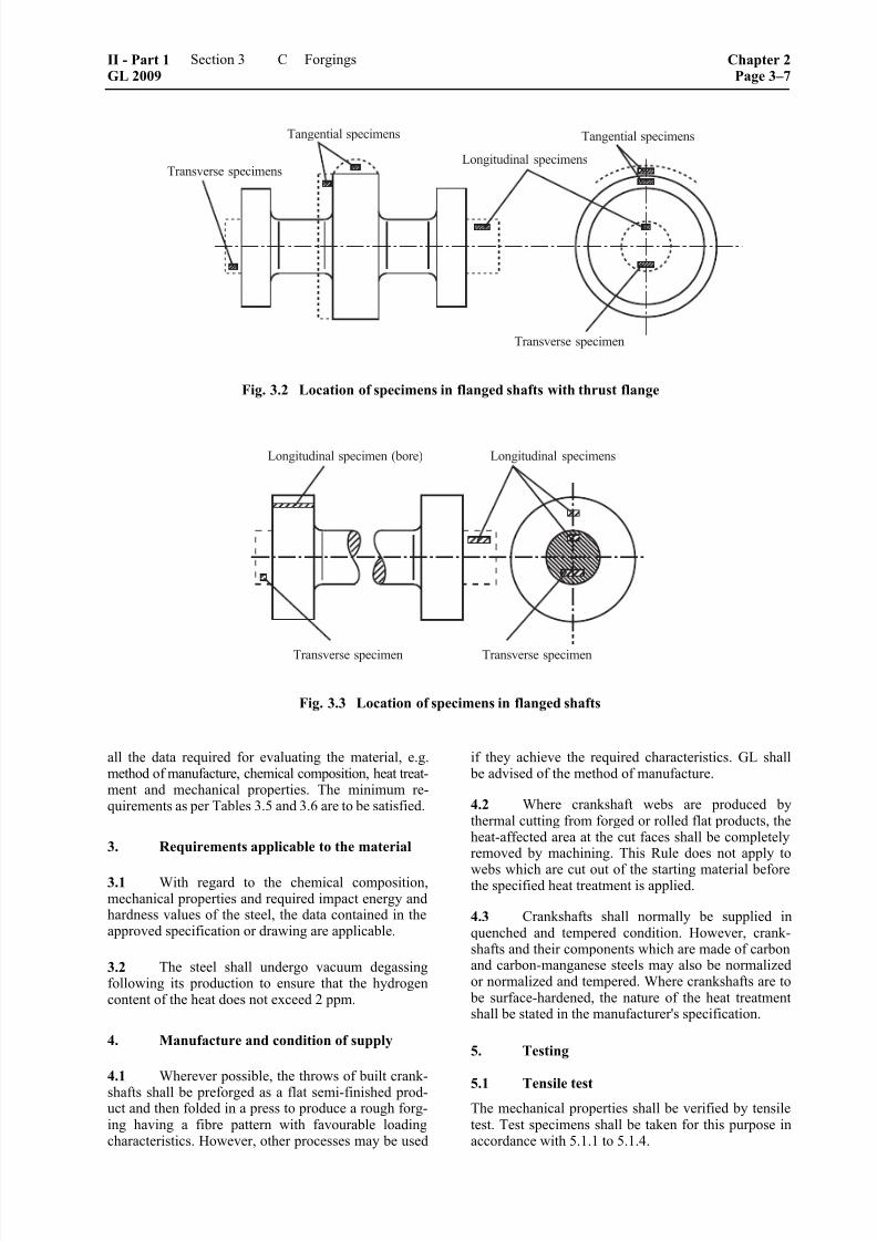
8/10/2019 Casting Material for Shipyards Etc
http://slidepdf.com/reader/full/casting-material-for-shipyards-etc 63/150
Fig. 3.2 Location of specimens in flanged shafts with thrust flange
Fig. 3.3 Location of specimens in flanged shafts
all the data required for evaluating the material, e.g. method of manufacture, chemical composition, heat treat-ment and mechanical properties. The minimum re-quirements as per Tables 3.5 and 3.6 are to be satisfied.
3. Requirements applicable to the material
3.1 With regard to the chemical composition,mechanical properties and required impact energy andhardness values of the steel, the data contained in theapproved specification or drawing are applicable.
3.2 The steel shall undergo vacuum degassingfollowing its production to ensure that the hydrogencontent of the heat does not exceed 2 ppm.
4. Manufacture and condition of supply
4.1 Wherever possible, the throws of built crank-
shafts shall be preforged as a flat semi-finished prod-uct and then folded in a press to produce a rough forg-ing having a fibre pattern with favourable loadingcharacteristics. However, other processes may be used
if they achieve the required characteristics. GL shall be advised of the method of manufacture.
4.2 Where crankshaft webs are produced bythermal cutting from forged or rolled flat products, theheat-affected area at the cut faces shall be completelyremoved by machining. This Rule does not apply to
webs which are cut out of the starting material beforethe specified heat treatment is applied.
4.3 Crankshafts shall normally be supplied inquenched and tempered condition. However, crank-shafts and their components which are made of carbonand carbon-manganese steels may also be normalizedor normalized and tempered. Where crankshafts are to
be surface-hardened, the nature of the heat treatmentshall be stated in the manufacturer's specification.
5. Testing
5.1 Tensile testThe mechanical properties shall be verified by tensiletest. Test specimens shall be taken for this purpose inaccordance with 5.1.1 to 5.1.4.
II - Part 1GL 2009
Section 3 Forgings Chapter 2Page 3–7
C

8/10/2019 Casting Material for Shipyards Etc
http://slidepdf.com/reader/full/casting-material-for-shipyards-etc 64/150
Table 3.5 Mechanical and technological properties of carbon and carbon manganese steel forgings in nor-malized or quenched and tempered condition for room temperature
Impact energyElongation
( )o o
for L 5,65 S
A [%]
min.
Reductionin area
Z
[%]
min.
KV 3
[J]
min.
KU
[J]
min.
Minimumtensile
strength 1, 2
R m
[N/mm2]
Relevantheat
treatmentdiameter
[mm]
Yieldstrength
R eH
[N/mm2]min.
long. tang. trans. long. tang. trans. long. tang. trans. long. tang. trans.
Brinell
hardnessHB
(Guide
values)
≤ 250 40 32 25 38 30 25
> 250 ≤ 500 32 25 18 30 25 20360
> 500 ≤ 1000
180 28 24 20 50 42 35
32 25 18 29 23 18
95 – 125
≤ 250 40 32 25 38 30 25
> 250 ≤ 500 32 25 18 30 25 20400
> 500≤
1000
200 26 23 19 50 42 35
32 25 18 27 22 17
110 – 150
≤ 250 38 30 22 35 27 22
> 250 ≤ 500 32 25 18 30 25 20440
> 500 ≤ 1000
220 24 21 18 50 42 35
30 24 18 25 20 15
125 – 160
≤ 250 35 27 22 32 25 22
> 250 ≤ 500 32 25 18 30 25 20480
> 500 ≤ 1000
240 22 19 16 45 38 30
26 24 14 22 17 12
135 – 175
≤ 250 32 25 20 30 25 20
> 250 ≤ 500 25 20 15 25 20 17520
> 500 ≤ 1000
260 21 18 15 45 38 30
24 18 13 20 15 11
150 – 185
≤ 250 25 20 15 25 20 17
> 250 ≤ 500 25 20 15 25 20 17560
> 500 ≤ 1000
280 20 17 14 40 34 27
23 14 12 19 12 10
160 – 200
≤ 250 18 15 12 20 17 15
> 250 ≤ 500 18 15 12 20 17 15600
> 500 ≤ 1000
300 18 16 13 40 34 27
18 14 12 17 12 10
175 – 215
≤ 250 18 15 12 20 17 15640
> 250 ≤ 500320 17 15 12 40 32 27
18 15 12 20 17 15185 – 230
≤ 250 18 15 12 20 17 15
680> 250 ≤ 500
340 16 14 12 40 32 2718 15 12 20 17 15
200 – 240
≤ 250 18 15 12 20 17 15720
> 250 ≤ 500360 15 13 11 40 32 27
18 15 12 20 17 15210 – 250
≤ 250 18 15 12 20 17 15760
> 250 ≤ 500380 14 12 10 35 30 24
18 15 12 20 17 15225 – 265
1 Where the minimum tensile strength of a steel grade falls between two of the graduated values, the requirements are to be determined by
interpolation, see 4.2.2.
2 The tensile strength determined by testing may not exceed the specified minimum tensile strength, if less than 600 N/mm2, by more than
120 N/mm2. Where the minimum tensile strength is ≥ 600 N/mm2 not more than 150 N/mm2 may be exceeded.3 The propeller shafts, rudderstocks and heel pintles of ships with ice class symbols are subject to the impact energy values stipulated in 4.3.
Chapter 2Page 3–8
Section 3 Forgings II - Part 1GL 2009
C

8/10/2019 Casting Material for Shipyards Etc
http://slidepdf.com/reader/full/casting-material-for-shipyards-etc 65/150
Table 3.6 Mechanical and technological properties of alloy steel forgings in quenched and tempered condi-tion for room temperature
Impact energyElongation
( )o ofor L 5,65 S
A [%]
min.
Reduction
in area
Z
[%]
min.
KV 4
[J]
min.
KU 4
[J]
min.
Minimum
tensilestrength 1, 2
R m
[N/mm2]
Relevant heat
treatment
diameter
[mm]
Yield
strength3
R eH
[N/mm2]min.
long. tang. trans. long. tang. trans. long. tang. trans. long. tang. trans.
Brinell
hardnessHB
(Guide
values)
≤ 250 20 18 16 41 32 24 35 30 24550
> 250 ≤ 500 18 16 14
50 45 35
32 25 18 30 25 20
160 – 200
≤ 250 20 18 16 41 32 24 35 30 24600
> 250 ≤ 500 18 16 14
50 45 35
32 25 18 30 25 20
175 – 215
≤ 250 18 16 14 32 28 22 30 27 23650
> 250≤
50017 15 13
50 45 35
25 18 13 25 20 15
190 – 235
≤ 250 17 15 13 32 28 22 30 27 23700
> 250 ≤ 500 16 14 12
50 45 35
25 18 13 25 20 15
205 – 245
≤ 250 17 15 13 32 26 20 30 26 22750
> 250 ≤ 500
0,6 ×
minimum
tensile
strength
15 13 11
45 40 30
25 18 13 25 20 15
215 – 260
≤ 250 15 14 12 32 26 20 30 26 22800
> 250 ≤ 500 14 12 10
45 40 30
25 18 13 25 20 15
235 – 275
≤ 250 14 13 11 27 23 18 29 25 20850
> 250 ≤ 500 13 11 10
45 40 30
25 18 13 25 20 15
245 – 290
≤
250 14 13 11 27 23 18 29 25 20900> 250 ≤ 500 13 11 10
40 35 27
25 18 13 25 20 15
260 – 320
≤ 250 13 11 10 25 21 16 29 25 20950
> 250 ≤ 500 12 10 10
40 35 27
25 18 13 25 20 15
275 – 340
≤ 250 12 11 10 25 21 16 25 22 181000
> 250 ≤ 500 12 10 10
40 35 27
25 18 13 25 20 15
290 – 365
≤ 250 11 10 8 25 18 13 25 20 151050
> 250 ≤ 500 11 10 8
40 35 27
25 18 13 25 20 15
310 – 375
≤ 250 11 10 8 25 18 13 25 20 151100
> 250≤
500
0,7 ×
minimum
tensile
strength
11 10 8
40 35 27
25 18 13 25 20 15
320 – 385
1 Where the minimum tensile strength of a steel grade falls between two of the graduated values, the requirements are to be determined by
interpolation, see 4.2.2.
2 The tensile strength determined by testing may not exceed the specified minimum tensile strength, if less than 900 N/mm2, by more than
150 N/mm2. Where the minimum tensile strength is 900 N/mm2 not more than 200 N/mm2 may be exceeded.
3 For case-hardening steels a value of 60 % of the specified minimum tensile strength is sufficient irrespective of the value of the tensile
strength.
4 Where the heat treatment diameter is > 500 mm, the requirements shall be agreed with GL.
II - Part 1GL 2009
Section 3 Forgings Chapter 2Page 3–9
C

8/10/2019 Casting Material for Shipyards Etc
http://slidepdf.com/reader/full/casting-material-for-shipyards-etc 66/150
5.1.1 Independently of the selection of test speci-mens according to test batches as prescribed in 5.1.3, at least one longitudinal or transverse tensile test speci-men shall be taken from the driven side of each crank-shaft. Where a solid forged crankshaft weighs more than
3000 kg, test specimens shall be taken from both ends, on the driven side as a transverse specimen. The weight applicable is the weight of the crankshaft in the heat-treated condition minus the weight of the test sections.
5.1.2 Where the throws are machined or flame cutfrom a preforged crankshaft, a second set of testspecimens shall be taken in the transverse directionfrom the material removed from the throw furthestfrom the driven side, cf. Fig. 3.4.
The test sections may not be removed prior to quench-ing and tempering.
Fig. 3.4 Location of test specimens in crankshafts
5.1.3 Crankshafts of the same dimensions up to aweight in heat-treated condition of 500 kg whichoriginate from the same heat and form part of thesame heat treatment batch may be grouped into test
batches in accordance with Table 3.1, A.10.2.3. Forquenched and tempered crankshafts, two tensile testspecimens shall be taken from each test batch; fornormalized shafts, one specimen is sufficient.
5.1.4 Transverse test specimens shall be taken fromforged throws. Unless otherwise agreed with GL, atleast one specimen shall be taken from each forging.
5.1.5 Where two test specimens are taken fromlarge crankshafts, the difference between the measuredtensile strength values may not exceed the magnitudesstated in B.4.2.3.
5.2 Notched bar impact test
Each forging or unit test quantity, as applicable, shall be subjected to the notched bar impact test. The num- ber of sets of specimens (each comprising 3 speci-mens) and their position are subject to the conditionsstated in 5.1.1 to 5.1.4 for tensile test specimens.
5.3 Hardness testing
5.3.1 Where testing is performed in test batches, atleast 10 % of the crankshafts shall be subjected tohardness tests.
The method of hardness testing and the position of thehardness testing impressions on the forgings shall beagreed with GL.
5.3.2 The differences in the hardness values meas-
ured at different points on the forging or on differentunits within a test batch may not exceed the magni-tudes stated in B.4.4.2.
5.4 Test of surface finish and dimensions
The crankshaft manufacturer shall test the surfacefinish and dimensions of the crankshafts and give themeasurement records to the Surveyor. He shall also
present the crankshafts to the Surveyor for final in-spection and hold in readiness the measuring instru-ments required for checking the dimensions.
5.5 Non-destructive testing
Crankshafts shall be subjected to non-destructivetesting according to the scope stipulated in G.
D. Forgings for Gears
1. Scope
These Rules are applicable to forgings made of car- bon, carbon-manganese and low alloy steels which areintended for the manufacture of wheels and wheelrims for the gears of the main engine and auxiliary
equipment.
2. Suitable grades of steel
On condition that they satisfy the requirements of 6., the following grades of steel may be used:
2.1 Quenched and tempered steels conforming toEN 10083-1, case hardening steels conforming toEN 10084 and nitriding steels conforming toEN 10085, provided that proof has been furnished ofthe suitability of the individual grade of steel for theintended purpose. Table 3.7 contains a selection ofsuitable steel grades.
2.2 Steels conforming to other standards, pro-vided that they are comparable with the steel gradesspecified in 2.1 and proof has been furnished of theirsuitability for the intended purpose.
Table 3.7 Suitable steel grades for gears
Steel grade Standard
42CrMo4 EN 10083-1
16MnCr5
20MnCr5
18CrNiMo7-6
EN 10084
Chapter 2Page 3–10
Section 3 Forgings II - Part 1GL 2009
D

8/10/2019 Casting Material for Shipyards Etc
http://slidepdf.com/reader/full/casting-material-for-shipyards-etc 67/150
2.3 Steels conforming to particular materialspecifications, provided that GL has authorised theiruse. To this end, the gear manufacturer shall submitthe corresponding specifications for approval. Thesespecifications shall contain all the data required for
their evaluation, e.g. method of manufacture, chemicalcomposition, heat treatment, surface hardening andmechanical properties.
3. Welded wheels
Where gear wheels are made up of components welded
together, full details of the welding process, the scope of non-destructive testing and the acceptability criteria for welding defects shall be submitted to GL for approval. The characteristics of the welds shall first be demon-strated by a welding procedure specification test.
4. Heat treatment
4.1 Forgings for which surface hardening after the
cutting of the teeth is not specified shall be quenched
and tempered. Carbon and carbon-manganese steels
may also be normalized and tempered.
4.2 In the case of forgings which undergo surfacehardening after the cutting of the teeth, the heat treat-ment depends on the nature of the surface hardening
process, as follows:
4.2.1 After carburization, case-hardening steels areto be hardened and then tempered at low temperature.
The depth of case hardening, the time-temperaturecycle and the hardness range (min/max) shall be statedin the specification.
4.2.2 Steels for induction hardening shall normally be quenched and tempered prior to hardening. Carbonand carbon-manganese steels may also be normalizedinstead of quenching and tempering. The nature of theheat treatment, the depth of hardening, the hardeningtemperatures, the quenching media and the hardnessrange (min/max) shall be stated in the specification.
4.2.3 Nitriding steels shall be quenched and tem- pered prior to nitriding. Where possible, nitriding shall be effected by the action of gases. The nature of theheat treatment, the nitriding depth and the hardnessrange (min/max) shall be stated in a specification.
4.3 The heat treatments and surface hardening processes referred to in 4.2 shall be carried out in sucha way as to produce uniform hardening of the depthand hardness stipulated in the specification. GL re-serves the right to require the manufacture of sampleson which the uniformity, depth and hardness of thesurface layer shall be demonstrated.
5. Dimensions, dimensional and geometricaltolerances
The data shown in the drawings relating to the orderare applicable.
6. Requirements applicable to the material
6.1 Chemical composition
6.1.1 The chemical composition is subject to thelimit values specified in the relevant standard or theapproved specification.
6.1.2 Where forgings are to be used for weldedwheel assemblies, their composition shall be speciallydetermined to suit the method of welding and shall besubmitted to GL for approval.
6.2 Mechanical and technological properties
For quenched and tempered steels, the minimum re-quired values for the yield strength, elongation andreduction in area specified in Tables 3.5 and 3.6 in C.shall be met in relation to the prescribed minimumtensile strength.
For case-hardening steels, the requirements specified in
Table 3.8 apply to specimens which have undergone
heat treatment together with the forging (coupons).
Table 3.8 Required values for mechanical and technological properties of specimens made of coupons
Impact energyElongation
A 1
[%]
min.
Reduction
in area
Z 1
[%]
min.
KV 1
[J]
min.
KU 1
[J]
min.
Steel grade
Sample
dia.
[mm]
Yield
strtengthR eH
[N/mm2]min.
Tensile
strengthR m
[N/mm2] l t, q l t, q l t, q l t, q
16MnCr5 590 780 –1080 10 8 40 27 22 16 24 18
20MnCr5 690 980 –1280 8 6 35 27 18 13 20 15
18CrNiMo7-6
30
785 1080–1320 8 6 35 27 18 13 20 15
16MnCr5 440 640 –940 11 9 40 27 22 16 24 18
20MnCr5 540 780 –1080 10 8 35 27 22 16 24 18
18CrNiMo7-6
63
685 980 –1280 8 6 35 27 18 13 20 15
1 Orientation of specimen axis: l = longitudinal, t = tangential, q = transverse
II - Part 1GL 2009
Section 3 Forgings Chapter 2Page 3–11
D

8/10/2019 Casting Material for Shipyards Etc
http://slidepdf.com/reader/full/casting-material-for-shipyards-etc 68/150
6.3 Hardness
For all gear components, the hardness values pre-scribed for the tooth area in the specification or ap-
proval drawing are mandatory.
7. Testing
The following tests shall be performed:
7.1 Test of chemical composition
The material manufacturer shall determine the compo-sition of each heat and issue a relevant certificate.
7.2 Tensile test on finally heat-treated, induc-
tion-hardened and nitrided forgings
The mechanical properties shall be verified by tensiletest. Test specimens shall be taken as follows:
7.2.1 Pinions over 200 mm in diameter:
If the diameter in the area of the teeth is greater than
200 mm, a tangential test specimen shall be taken from
a position adjoining the tooth area, see Fig. 3.5. If the
dimensions of the blank do not allow a specimen to be
taken from this position, then a transverse specimen may
be taken from an extension of the bearing journal. If the
diameter of the bearing journal is 200 mm or less, then
a longitudinal specimen may be taken. If the length of the finished tooth system is more than 1250 mm, test specimens shall be taken from both ends of the blank.
7.2.2 Pinions up to 200 mm in diameter:In the case of small pinions with diameters of up to 200
mm in the area of the teeth, a longitudinal test specimen
shall be taken from the bearing journal, see Fig. 3.5.
Fig. 3.5 Pinion
7.2.3 Gear wheels:
A tangential test specimen shall be taken from gearwheel blanks, see Fig. 3.6.
7.2.4 Wheel rims:
In the case of wheel rims which are normally made by piercing a bar and enlarging the hole by forging orrolling, a tangential test specimen shall be taken, seeFig. 3.7.
Fig. 3.6 Gear wheel
Fig. 3.7 Wheel rim
If the diameter of the tooth system exceeds 2500 mmor the heat-treated workpiece, excluding the materialfor testing, weighs more than 3000 kg, specimensshall be taken from two diametrically opposite pointson the rim.
7.2.5 Pinion blanks:
From hollow pinion blanks, the length of whose fin-ished tooth system is 1 250 mm or less, a test speci-men shall be taken from one end at right angles to thelongitudinal axis of the workpiece; where the length ofthe tooth system is more than 1 250 mm, specimensshall be taken from both ends, see Fig. 3.8.
Fig. 3.8 Hollow pinion
A distinction is to be made here according to whetherthe workpiece has been forged as a solid blank andthen drilled or has been produced by piercing a roughforging and opening up the hole over a mandrel.
Where the workpiece is drilled, the specimens areconsidered to be transverse, but where the blank isexpanded over a mandrel the specimens are consid-ered to be tangential.
Chapter 2Page 3–12
Section 3 Forgings II - Part 1GL 2009
D

8/10/2019 Casting Material for Shipyards Etc
http://slidepdf.com/reader/full/casting-material-for-shipyards-etc 69/150
7.3 Tensile test on case-hardening steels
7.3.1 The respective test sections are to be heat-treated together with the associated gear component orthe test batch. For this purpose, the test sections are to
be machined to a diameter corresponding to thesmaller of the following two values:
0,25 × diameter of tooth system or
63 mm diameter
If the diameter of the test specimen is less than63 mm, in agreement with the surveyor a test speci-men with standardized dimensions may be used (e.g.30 mm diameter according to DIN 17210).
Tensile test specimens shall then be taken from thetest sections and tested.
7.3.2 The gear manufacturer has the option of pro-ducing test sections with a cross section greater thanthat specified in 7.3.1. However, for the final harden-ing and tempering the pieces shall be given the speci-fied dimensions.
7.4 Strength differences in the forging
Where two test specimens are taken from large for-gings, the difference between the measured tensilestrength values may not exceed the magnitudes speci-fied in B.4.2.3.
7.5 Notched bar impact test
Each forging or unit test quantity, as applicable, shall be subjected to the notched bar impact test. The num- ber of sets of specimens (each comprising 3 speci-mens), the positions in the forgings or test sectionsfrom which the specimens are taken and their heattreatment are subject to the provisions of 7.2 and 7.3,as appropriate.
The test may be carried out on Charpy V- or CharpyU-notch samples as chosen by the manufacturer.
7.6 Hardness test
7.6.1 After heat treatment but before the cutting ofthe teeth, hardness tests are to be carried out on allforgings at the points specified in the approval draw-ings. Where the length L of the teeth of a gear compo-nent exceeds 500 mm, testing shall be performed at
both ends of the tooth system.
7.6.2 On all surface-hardened gear parts, additionalhardness tests are to be carried out on the teeth afterhardening and grinding. The number of measuring
points shall be such that compliance with the specifiedhardness values can be verified over the periphery andthe width of the tooth system.
7.6.3 The differences in the values measured at the prescribed points on a forging or on different unitswithin a test batch may not exceed the magnitudesspecified in B.4.4.2.
7.7 Test of surface finish and dimensions
The gear manufacturer shall check the surface finish
and dimensions of the tooth system. The products shall then be presented to the Surveyor for final inspection
and he shall be given the measurement records. For retests by the Surveyor, the gear manufacturer shall hold the necessary measuring instruments in readiness.
7.8 Batchwise testing
Forgings with similar dimensions up to a weight inheat-treated condition of 300 kg which originate fromthe same heat and form part of the same heat treatment
batch may be grouped into test batches in accordancewith A.10.2, Table 3.1. Two test sections shall betaken from each test batch for the tensile test and thenotched bar impact test. Every forging shall be sub-
jected to a hardness test.
7.9 Non-destructive tests
7.9.1 The manufacturer shall carry out an ultra-sonic test on the tooth area of all forgings where thediameter of the tooth system exceeds 200 mm.
7.9.2 The entire tooth system of gear parts withsurface-hardened teeth shall be tested for cracks usingthe magnetic particle or dye penetrant method.
The welds of gear wheels built up of separate partsshall be subjected to non-destructive testing of thescope specified at the time of the process approval.
The tests shall be performed in comliance with G.
E. Forgings for Boilers, Pressure Vessels,Process Equipment and Pipelines
1. Scope
1.1 These Rules are applicable to unalloyed andalloy steel forgings for the manufacture of flanges,nozzles, valve housings, socket welding and weldingneck components. Steel forgings tough at sub-zero
temperatures are subject to F.
1.2 In the case of forgings for steam boilers onvessels sailing under the German flag, the "TechnicalRules for Steam Boilers" of series TRD 100 shall becomplied with.
2. Suitable grades of steel
The following materials may be used:
2.1 Weldable unalloyed structural steels con-forming to EN 10250-2 up to an operating temperatureof 300 °C.
2.2 Forgings made of ferritic and martensiticsteels with specified properties at elevated tempera-tures conforming to EN 10222-2.
II - Part 1GL 2009
Section 3 Forgings Chapter 2Page 3–13
E

8/10/2019 Casting Material for Shipyards Etc
http://slidepdf.com/reader/full/casting-material-for-shipyards-etc 70/150
2.3 Forgings made of weldable fine-grainedstructural steels conforming to EN 10222-4.
2.4 Austenitic or austenitic-ferritic stainless steelforgings conforming to DIN 17440, EN 10222-5 or
"Stahl-Eisen-Werkstoffblatt" (Iron and Steel MaterialSpecification) SEW 400.
2.5 Steel flanges conforming to DIN 2528.
2.6 Steels conforming to other standards or mate-rial specifications, provided that they are comparableto the steel grades listed in 2.1 to 2.5 and proof has
been furnished of their suitability for the intendedapplication. An initial test of product suitability may
be requested for this purpose. Ferritic steels shall addi-tionally satisfy the following minimum requirements.
2.6.1 The elongation (A) shall have the character-istic minimum values for the respective steel grades asspecified by GL; however, it shall be not less than14 % in transverse and tangential direction and notless than 16 % in longitudinal direction.
2.6.2 The impact energy shall have the characteris-tic minimum values for the respective steel grades asspecified by GL; however, it shall be not less than 27 Jin transverse and tangential direction and 39 J in lon-gitudinal direction at room temperature in tests con-ducted with Charpy V-notch specimens. This value isan average value from three tests, in which one indi-vidual value may be below the prescribed averagevalue but not less than 70 % of the average value.
3. Heat treatment and condition of supply
All forgings shall be supplied in a heat treated condi-tion appropriate to the grade of steel. In the case ofunalloyed steel grades, normalizing may be replaced
by an equivalent method of temperature control duringor after forging or rolling, provided that GL has ap-
proved the method.
If parts are manufactured from bars or plates by ma-chining, heat treatment of the starting material is suffi-
cient.
4. Requirements applicable to the material
4.1 General requirements
The chemical composition, mechanical properties, andimpact energy and hardness values of the steel shallconform to the standards stated in 2.1 to 2.5 or, whereapplicable, the data contained in the approved specifi-cations.
4.2 Weldability
Steels conforming to these Rules shall be weldable byestablished workshop methods. Depending on thechemical composition, preheating and/or post-weldheat treatments may be required for this purpose.
4.3 Resistance to intercrystalline corrosion
Austenitic steel grades shall be resistant to intercrys-talline corrosion in the condition in which they aresupplied. If forgings for welded assemblies (e.g. weld-on valves, flanges) are to be used without post-weld
heat treatment, steel grades which are corrosion-resistant in this condition as well shall be selected, e.g.steels stabilized with Ti or Nb or steels with carbon
contents of C ≤ 0,03 %.
5. Testing
The forgings shall be presented for testing in finishedcondition (condition of supply) and shall undergo thefollowing tests. With regard to forgings for steam
boilers, 1.2 shall be complied with.
5.1 Tensile testing
5.1.1 The mechanical properties shall be verified by a tensile test. For preparing the test specimens,forgings with similar dimensions and nominal weightsup to 1 000 kg which originate from the same heat andform part of the same heat treatment batch may begrouped into test batches in accordance with A.10.2,Table 3.1. For normalized forgings, one specimenshall be taken from each test batch, while for forgingsin other heat-treated conditions, 2 specimens shall be
taken from each test batch. For quantities of ≤ 10, and
≤ 30 in the case of nominal weights not exceeding15 kg, one specimen is sufficient.
5.1.2 For batchwise testing, the hardest and softestforgings in each batch shall be selected for testing, see5.3.
5.1.3 In the case of forgings with unit weights ofmore than 1 000 kg, a test specimen shall be takenfrom every forging.
5.2 Notched bar impact test
The forgings shall be subjected to the notched bar impact test. The number of sets of test specimens (3 Charpy V-notch specimens per set) shall be determined in the same
way as the number of tensile test specimens.
5.3 Hardness tests
5.3.1 In the case of quenched and tempered forgings, with the exception of flanges with standardized dimen-sions, a hardness test shall be performed on each forging.
5.3.2 Flanges with standardized dimensions shall be subjected to the following scope of testing:
– normalized steels: at least 3 %,
– quenched and tempered, and austenitic-ferriticsteels: at least 10 % of the same test batch
5.3.3 In the case of parts not mentioned in para-graphs 5.3.1 and 5.3.2, at least 20 % of each test batchshall be tested.
Chapter 2Page 3–14
Section 3 Forgings II - Part 1GL 2009
E

8/10/2019 Casting Material for Shipyards Etc
http://slidepdf.com/reader/full/casting-material-for-shipyards-etc 71/150
5.4 Test of surface finish and dimensions
The manufacturer shall test the surface finish anddimensions of the products and shall then present the
parts to the Surveyor for final acceptance testing.
5.5 Test for use of correct material
Alloy steel forgings shall be subjected by the manu-facturer to appropriate tests to ensure that the correctmaterial has been used.
5.6 Non-destructive testing
Forgings with a nominal weight of over 300 kg shall be subjected by the manufacturer to an ultrasonic testand, where necessary, a supplementary test for surfacecracks. The tests shall be performed in compliancewith G.
5.7 Testing of resistance to intercrystallinecorrosion
The manufacturer shall check the resistance to inter-crystalline corrosion of austenitic and austenitic-ferritic steel forgings intended for welded assembliesand - where stipulated in the order - of other austeniticsteels as well. Testing shall be carried out in the fol-lowing conditions:
– steels containing C ≤ 0,0 3% and stabilizedsteels: after sensitizing heat treatment (700 °C,30 min, quenching in water)
– all other steels: in the condition of supply. Atleast two specimens from each heat shall betested in accordance with a recognized standard(e.g. ISO 3651-2).
F. Steel Forgings Tough at Sub-Zero Tem-
peratures
1. Scope
1.1 These Rules are applicable to steel forgingstough at sub-zero temperatures and high-strength,quenched and tempered steel forgings which are in-tended for cargo and processing equipment on gastankers, e.g. flanges, valve parts, weld-on and socketwelding parts.
1.2 In the case of forgings which are intended for pressure-liquefied ammonia at design temperatures notlower than 0 °C, e.g. forged flanges, rings and connec-tions, the boundary values given in Section 1, F.8.1.1,Table 1.18 for chemical composition and in Section 1,F.8.2.2 for mechanical properties are to be observed.The required values for impact energy given inSection 1, F.8.3 shall also apply.
1.3 In the case of high-strength, quenched and
tempered fine-grained structural steel forgings having
nominal yield strengths of between 420 and 690 N/mm2
which are designed for gas tanks with design tempera-tures no lower than 0 °C, the requirements according to
1.2 apply.
2. Approved steel grades
The following grades of steel may be used within theminimum design temperature limits specified in Table3.9, provided that they satisfy the requirements of 5.
2.1 Standardized steels conforming to Table 3.9.
2.2 Other steels conforming to other standards ormaterial specifications, provided that they are compa-rable with the steel grades specified in 2.1 and proofhas been furnished of their suitability for the intendedapplication. An initial approval test may be requiredfor this purpose.
3. Heat treatment and condition of supply
All forgings shall be supplied in a heat-treated condi-tion appropriate to the grade of steel, i. e normalized,quenched and tempered, or solution-annealed andquenched.
If parts are manufactured from bars or plates by ma-chining, heat treatment of the starting material is suffi-cient.
4. Dimensions, dimensional and geometrical
tolerances
The data in the standards or specifications are applicable.
5. Requirements applicable to the material
5.1 General requirements
The chemical composition, the mechanical propertiesand the hardness shall conform to the data containedin the relevant standards or approved specifications.
5.2 Weldability
Steels conforming to these Rules shall be weldable byestablished workshop methods.
5.3 Impact energy at low temperatures
The required impact energy values specified in Table3.10 for the grade of steel concerned shall be met atthe test temperatures specified in the table, usingCharpy V-notch specimens.
5.4 Resistance to intercrystalline corrosion
Austenitic steel grades shall be resistant to intercrys-talline corrosion in the condition in which they aresupplied. If forgings are to be used for welded assem-
blies (e.g. weld-on valves, flanges) without post-weld
heat treatment, steel grades which are corrosion-resistant in this condition as well shall be selected, e.g.steels stabilized with Ti or Nb or steels with carbon
contents of C ≤ 0,03%.
II - Part 1GL 2009
Section 3 Forgings Chapter 2Page 3–15
F

8/10/2019 Casting Material for Shipyards Etc
http://slidepdf.com/reader/full/casting-material-for-shipyards-etc 72/150
Table 3.9 Approved grades of forging steels tough at sub-zero temperatures
Type of steelApproved minimum
design temperature Steel grade or
Material no. Standard
P285NH
P285QH
P355N
Weldable fine-grainedstructural steels –20 °C
1
P355QH
EN 10222-4
0,5 % nickel steel –55 °C 13MnNi6-3 EN 10222-3
2,25 % nickel steel –65 °C ––
3,5 % nickel steel –90 °C 12Ni14
–105 °C
12Ni195 % nickel steel ⎧⎨⎩
–165 °C 2 X12Ni5
9 % nickel steel –165 °C X8Ni9
EN 10222-3
1.4301 (304) 3
1.4307 (304 L)
1.4401 (316)
1.4404 (316 L)
1.4541 (321)
Austenitic steel –165 °C
1.4550 (347)
EN 10222-5
1 Lower design temperatures may be established by means of an approval test.2 The minimum design temperature of – 165 °C is only valid if this has been demonstrated by an approval test.3 The numbers in brackets denote comparable steels conforming to AISI standards.
Table 3.10 Required impact energy values for steel forgings tough at sub-zero temperatures
Impact Energy
KV
[J] 1
min.
Type of steel Test
temperature
longitudinal transverse
Weldable fine-grainedstructural steels and
0,5 % nickel steel
5 K below minimum designtemperature but at least
– 20 °C
27 (19) 22 (15)
2,25 % nickel steel – 70 °C
3,5 % nickel steel – 95 °C
5 % nickel steel –110 °C
5 % nickel steel –196 °C 2
9 % nickel steel –196 °C
34 (24) 24 (17)
Austenitic steels –196 °C 41 (27) 27 (19)1 Average value measured on 3 Charpy V-notch specimens; the figures in brackets indicate the minimum individual value.2 The test temperature of –196 °C applies if the 5 % nickel steel has been approved for a minimum design temperature of –165 °C.
Chapter 2Page 3–16
Section 3 Forgings II - Part 1GL 2009
F

8/10/2019 Casting Material for Shipyards Etc
http://slidepdf.com/reader/full/casting-material-for-shipyards-etc 73/150
6. Testing
The forgings shall be presented for testing in the fin-ished condition (condition of supply) and subjected tothe tests specified below.
6.1 Tensile test
6.1.1 The mechanical properties shall be tested bytensile test. For preparing the test specimens, forgingswith similar dimensions and nominal weights up to1 000 kg which originate from the same heat and form
part of the same heat treatment batch may be groupedinto test batches in accordance with A.10.2, Table 3.1.
For normalized forgings, one specimen shall be taken from
each test batch, while for forgings in other heat-treated
conditions, 2 specimens shall be taken from each test batch.
For quantities of ≤ 10 - and ≤ 30 in the case of nominal weights not exceeding 15 kg - one specimen is sufficient.
6.1.2 For the batchwise testing, the hardest andsoftest forgings in each batch shall be selected fortesting, see 6.3.
6.1.3 In the case of forgings with unit weights ofmore than 1 000 kg, a test specimen shall be takenfrom every forging.
6.2 Notched bar impact test
The forgings shall be subjected to the notched barimpact test using Charpy V-notch specimens. Thenumber of sets of test specimens (3 specimens per set)
shall be determined in the same way as the number oftensile test specimens. The tests shall be performed atthe test temperatures specified in Table 3.10.
6.3 Hardness testing
6.3.1 In the case of forgings in quenched and tem- pered condition, with the exception of flanges withstandardized dimensions, a hardness test shall be per-formed on every forging.
6.3.2 Flanges with standardized dimensions shall be subjected to the following scope of testing:
– Normalized steels: at least 3 %,
– quenched and tempered, austenitic and austenitic-ferritic steels: at least 10 % of the same test batch
6.3.3 In the case of parts not mentioned in 6.3.1 and
6.3.2, at least 20 % of each test batch shall be tested.
6.4 Test of surface finish and dimensions
The manufacturer shall test the surface finish anddimensions of the products and then present the partsto the Surveyor for final acceptance testing.
6.5 Test for use of correct materialAlloy steel forgings shall be subjected by the manu-facturer to appropriate tests to ensure that the correctmaterial has been used.
6.6 Non-destructive testing
Forgings with a nominal weight of over 300 kg shall be subjected by the manufacturer to an ultrasonic testand, where necessary, a supplementary test for surfacecracks. The test shall be performed in compliance withG.
6.7 Test of resistance to intercrystalline corro-sion
The manufacturer shall check the resistance to inter-crystalline corrosion of austenitic steel forgings in-tended for welded assemblies and - where stipulated inthe order - other austenitic steels as well. Testing shall
be carried out in the following conditions:
– steels containing C ≤ 0,03 % and stabilizedsteels: after sensitizing heat treatment (700 °C,
30 min, quenching in water) – all other steels: in the condition of supply. At
least two specimens from each heat shall betested in accordance with a recognized standard(e.g. ISO 3651-2).
G. Non-destructive Testing of Forged Com-ponents
1. Scope of validity
1.1 These Rules apply to the non-destructivetesting of forged components for which in B. to F.appropriate requirements are prescribed, and for whichno other regulations or manufacturer specifications areagreed upon.
A list containing the forged components for whichnon-destructive testing is required and the specifictests to be performed is contained in H.
1.2 The general requirements for inspection bod-ies, inspection personnel, testing methods and certifi-cation of the results are prescribed in Chapter 1 – Prin-
ciples and Test Procedures, Section 3 and are manda-tory for all tests.
1.3 The methods indicated in these Rules con-cerning the magnetic particle test and ultrasonic testsare limited to the application of forged componentsmade of ferritic steel grades.
For forged components made of austenitic or austen-itic-ferritic steel grades the methods and acceptancecriteria for the ultrasonic and penetrant tests shall beagreed upon with GL individually. This may be per-formed based on standards or specifications from themanufacturer or the orderer.
1.4 Taking into account the prescriptions in 1.3,in these Rules the following testing methods are de-scribed, see Table 3.11.
II - Part 1GL 2009
Section 3 Forgings Chapter 2Page 3–17
G

8/10/2019 Casting Material for Shipyards Etc
http://slidepdf.com/reader/full/casting-material-for-shipyards-etc 74/150
Table 3.11 Test methods
Testing of MethodShort
name 2
Visual testing VT
Magnetic particle testing 1 MTExternal
condition
Penetrant testing PT
Internal
conditionUltrasonic testing UT
1 only for forged components made of ferritic steel grades
2 definition according to DIN EN 473
1.5 The methods and testing criteria indicated inG. are to be employed by the manufacturers and com-
panies performing the further processing.
In case the orderer wants further regulations to beapplied on specific forged components e.g. for enginesand turbines, he shall state this in a test specificationand make this known to the GL Surveyor.
Alternatively non-destructive testing may be per-formed in accordance with test specifications from themanufacturer or the orderer on condition that themethods and acceptance criteria fulfil the followingrequirements.
1.6 For testing, the forged components shall be
classified in inspection zones of type I, II and III, ac-cording to the possible effects of defects on the struc-tural integrity. For magnetic particle testing there will
be the addition of type IV. In inspection zone I the allow-able number and size of indications are the smallest.
For classifying in inspection zones the following prin-ciples are decisive:
– the operation loads to be expected
– the effects of the defects on the reliability of thecomponent
– possible risk of damage if the component fails
– Freedom of defects and surface condition afterthe final machining
For the most important forged components of the propulsion plant the classifying in inspection zones is prescribed in I. and J.
1.7 For forgings where in I. for magnetic particletesting and in J. for ultrasonic testing no classifying ininspection zones is indicated, the manufacturer ororderer shall prescribe the inspection zones in a testspecification taking into consideration the principlesin 1.6 and shall be make them known to the GL Sur-
veyor.Further, the test specification shall contain detailsconcerning the required acceptance criteria (e.g. qual-ity class according to EN 10228-1, -2, -3).
2. Performing the tests
2.1 After the inspector of the internal or externalinspection body in charge of testing has performed the
prescribed tests, the final machined forged compo-
nents shall be presented to the GL-Surveyor for visualtesting.
2.2 Concerning the tests it shall be differentiated between pre-testing and acceptance testing. With pretests, where decisions concerning the testabilityand the employability of the forged component aremade, they are in general the business of the manufac-turer.
Acceptance tests shall be performed preferably on thefinal machined component after the heat treatmentappropriate for the required properties has been per-formed.
If necessary acceptance tests may be performed at a production stage with little machining allowance, andfor ultrasonic testing after pre-machining in a condi-tion with less contours.
Details for this are to be prescribed in a test specifica-tion and to be made known to GL.
2.3 The Surveyor shall be informed by the manu-facturer or the company performing the further proc-essing about the intended tests. It is up to the discre-tion of the Surveyor to attend the tests.
2.4 The tests shall be performed for the zonesdescribed for the forged components in H. and J., orfor those indicated in the test specification. In case theresults indicate that further defects are present in theforged component, the test scope shall be extendedaccording to agreement with the Surveyor.
2.5 Indications exceeding the allowable size,number and position indicated in the tables shall beremoved if technically possible. Excavated areas at thesurface are to be subjected to retesting.
2.6 In case internal defects or defects close to thesurface cannot be removed by grinding with satisfac-tory results, the manufacturer, the orderer and the GL-Surveyor shall decide on the employability of theforged component.
3. Visual testing (VT)
3.1 The manufacturer shall verify for each pro-duction stage of the forged components the externalcondition and the compliance of the dimensions. Forg-ing defects are to be removed, unless they are re-moved by the following machining.
3.2 For the acceptance test the forged componentare to be presented to the Surveyor in final machinedcondition.
Chapter 2Page 3–18
Section 3 Forgings II - Part 1GL 2009
G

8/10/2019 Casting Material for Shipyards Etc
http://slidepdf.com/reader/full/casting-material-for-shipyards-etc 75/150
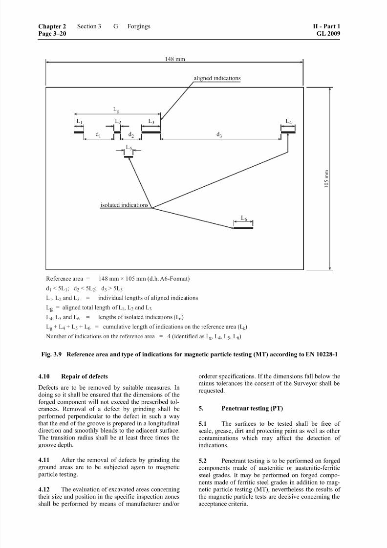
8/10/2019 Casting Material for Shipyards Etc
http://slidepdf.com/reader/full/casting-material-for-shipyards-etc 76/150
Fig. 3.9 Reference area and type of indications for magnetic particle testing (MT) according to EN 10228-1
4.10 Repair of defects
Defects are to be removed by suitable measures. Indoing so it shall be ensured that the dimensions of theforged component will not exceed the prescribed tol-erances. Removal of a defect by grinding shall be
performed perpendicular to the defect in such a waythat the end of the groove is prepared in a longitudinaldirection and smoothly blends to the adjacent surface.The transition radius shall be at least three times thegroove depth.
4.11 After the removal of defects by grinding theground areas are to be subjected again to magnetic
particle testing.
4.12 The evaluation of excavated areas concerningtheir size and position in the specific inspection zonesshall be performed by means of manufacturer and/or
orderer specifications. If the dimensions fall below the
minus tolerances the consent of the Surveyor shall berequested.
5. Penetrant testing (PT)
5.1 The surfaces to be tested shall be free ofscale, grease, dirt and protecting paint as well as othercontaminations which may affect the detection ofindications.
5.2 Penetrant testing is to be performed on forgedcomponents made of austenitic or austenitic-ferriticsteel grades. It may be performed on forged compo-
nents made of ferritic steel grades in addition to mag-netic particle testing (MT), nevertheless the results ofthe magnetic particle tests are decisive concerning theacceptance criteria.
Chapter 2Page 3–20
Section 3 Forgings II - Part 1GL 2009
G

8/10/2019 Casting Material for Shipyards Etc
http://slidepdf.com/reader/full/casting-material-for-shipyards-etc 77/150
5.3 Testing is to be performed in accordance withChapter 1 – Principles and Test Procedures, Section 3,K. or with other recognized standards such as e.g. EN571-1 and ISO 3452-2 or EN 10228-2 "Non-destructive testing of steel forgings, Part 2, Penetrant
testing".
5.4 The manufacturer shall prepare a test instruc-tion which shall contain at least the following infor-mation:
– details of the forged component including thematerial grade
– standards and specifications to be applied
– description of the test method
– employed testing agent system
– qualification of the inspection personnel
– surface areas to be tested
– required surface condition
– test criteria
– type of testing report
5.5 Unless otherwise agreed the testing accordingto Chapter 1 – Principles and Test Procedures, Section3, J. shall be performed on the final machined forgedcomponent and shall be performed in the presence ofthe Surveyor.
6. Ultrasonic testing (UT)
6.1 In the areas to be tested an appropriate sur-face condition shall be achieved which enables a fault-less coupling of the probe. Forging fin, scale, paint,dirt, unevenness and mechanical damages shall beremoved/corrected.
6.2 For premachined surfaces the average value
of the roughness shall be R a ≤ 25 μm. It is recom-
mended to agree on the appropriate class of quality forthe surface roughness according to Table 3.13.
6.3 The tests are to be performed in accordancewith Chapter 1 – Principles and Test Procedures, Sec-tion 3, L. Unless otherwise agreed it may also be per-formed according to EN 583-1, SEP 1921, SEP 1923,EN 10228-3 and/or other equivalent and recognized
standards, manufacturer or orderer specifications.
6.4 Unless no other recording levels were agreed on,
all indications exceeding a KSR 1 with diameter = 2 mm
shall be registered and evaluated and reported concern-ing their position, size, number and acceptability.
6.5 For indications which shall be registered, theamplitude of the back wall echo in the area of theindication is to be compared with the adjacent areasfree of indications.
Attenuations of the back wall echo with ≥ 4 dB are to be recorded in the testing report in dB.
6.6 Cracks of any type, size and distribution arenot allowed.
6.7 Indications exceeding the limiting valuescontained in Table 3.14 or 3.15, are to be regarded asdefects and in the first instance result in rejection ofthe forged component by the Surveyor. If the tests are
performed in accordance with a manufacturer or or-derer specification approved by GL then the limitingvalues indicated there are decisive and the procedureis accordingly.
6.8 The acceptance of the forged componentwhich in the first instance had been rejected is possi- ble on condition that after further evaluation of theindications performed by the orderer and the Surveyor
proof has been furnished that due to their size, posi-tion and distribution the defects have no considerableeffect on utilization of the forged component. In thiscase the acceptance of the forged component shall beapproved by an acceptance test certificate by both theorderer and the Surveyor.
_____________________________
1 KSR = disc shaped reflector (= Kreisscheibenreflektor)
Table 3.13 Recommendations for the surface quality
Class of quality and roughness R a [ m]
1 2 3 4Surface quality
25 12,5 12,5 6,3
machined × × × ×
machined and heat treated × × ×
forged ×
Note
" × " indicates the class of quality which can be achieved with the prescribed roughness.
II - Part 1GL 2009
Section 3 Forgings Chapter 2Page 3–21
G

8/10/2019 Casting Material for Shipyards Etc
http://slidepdf.com/reader/full/casting-material-for-shipyards-etc 78/150
Table 3.14 Acceptance criteria for ultrasonic testing of forged components
Forged component Zone
Size of the
max. allowable
KSR 1
[mm]
Max.
allowable length
of indications 3
[mm]
Min.
distance between
two indications 3
[mm]
Total of all
indication lengths
[mm]
per "m"component length
Propeller shafts I 2 ––
Intermediate shafts outside: 2 10 10 0,05 ⋅ d
Thrust shaftsII 2
inside: 4 15 10 0,10 ⋅ d
Rudder stocks and pintles
outside: 3 10 10 0,15 ⋅ d
Piston rods 4
III 2
inside: 6 15 10 0,20 ⋅ d
Connecting rods 5 I ––
Piston rods II 2 10 10 0,05 ⋅ d
Cross heads III 4 10 10 0,15 ⋅ d (s) 5
1 KSR = disc shaped reflector
2 The classifying in inspection zones is depicted in Fig. 3.15 to 3.20.
3 For accumulations of 2 or more isolated indications to be recorded the minimum distance between 2 adjacent indications shall be at least
of length of the major indication.
This applies to distances in axial as well as in thickness direction.
Isolated indications with smaller distance are to be regarded as aligned indication.
4 Piston rods with shaft diameter larger than 150 mm.
5 For rectangular cross-section "d" corresponds to the smallest side length "s".
Table 3.15 Acceptance criteria for ultrasonic testing of crank shafts
Size of the
max. allowable
KSR 1
Max.
allowable length
of indications
Min.
distance between
two indications 3
Max. number
of isolated
indications 3, 4Zone 2
[mm] [mm] [mm] [ − ]
Total of all
indication length
[mm] 4
per pin or journal,
or per web or
flange,
respectively
I –– –– –– –– ––
II 2 10 10 0,01 ⋅ d (D)1
mm⋅ 0,20 ⋅ d (D)
III 4 15 10 0,02 ⋅ d (D)1
mm⋅ 0,40 ⋅ d (D)
1 KSR = disc shaped reflector
2 The classifying in inspection zones is depicted in Fig. 3.21.
3 For accumulations of 2 or more isolated indications to be recorded the minimum distance between 2 adjacent indications shall be al least
of length of major indication.
This applies to distance in axial as well as in thickness direction.
Isolated indications with smaller distance are to be regarded as aligned indication.
4 Related to be diameter of crank pin "d" or to the diameter of main journal "D", respectively.
Chapter 2Page 3–22
Section 3 Forgings II - Part 1GL 2009
G
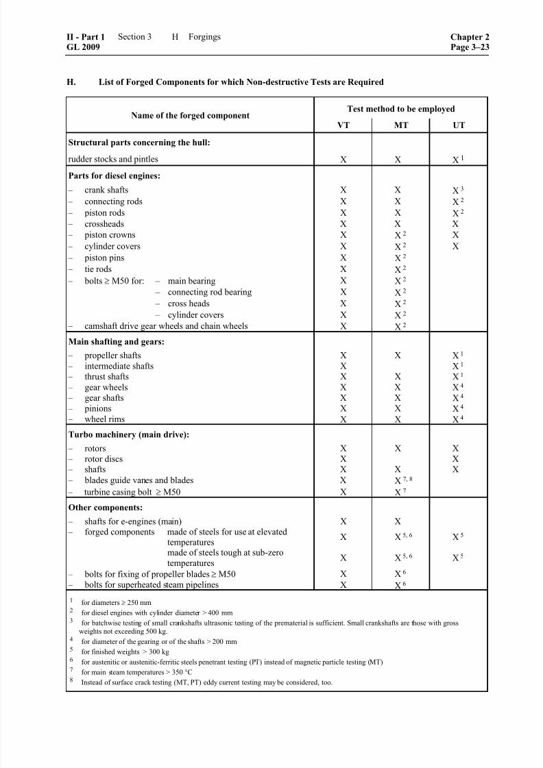
8/10/2019 Casting Material for Shipyards Etc
http://slidepdf.com/reader/full/casting-material-for-shipyards-etc 79/150
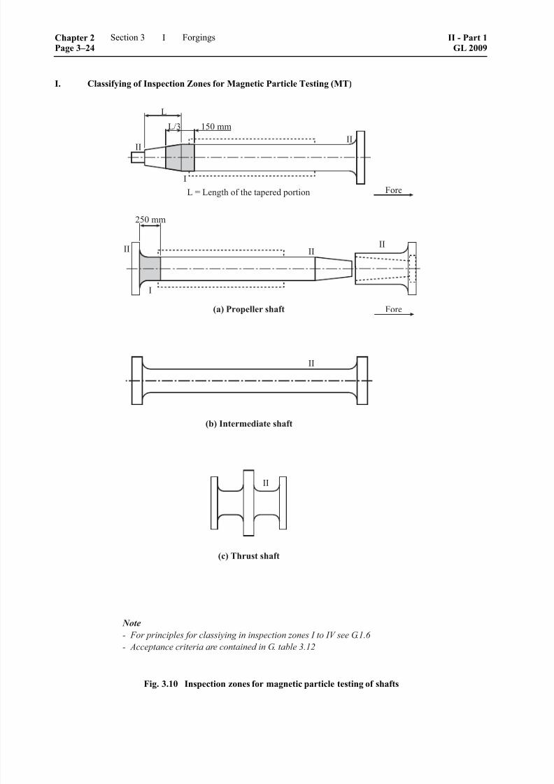
8/10/2019 Casting Material for Shipyards Etc
http://slidepdf.com/reader/full/casting-material-for-shipyards-etc 80/150
I. Classifying of Inspection Zones for Magnetic Particle Testing (MT)
Fig. 3.10 Inspection zones for magnetic particle testing of shafts
Chapter 2Page 3–24
Section 3 Forgings II - Part 1GL 2009
I

8/10/2019 Casting Material for Shipyards Etc
http://slidepdf.com/reader/full/casting-material-for-shipyards-etc 81/150
Fig. 3.11 Inspection zones for magnetic particle testing of rudder stocks and accessories
II - Part 1GL 2009
Section 3 Forgings Chapter 2Page 3–25
I

8/10/2019 Casting Material for Shipyards Etc
http://slidepdf.com/reader/full/casting-material-for-shipyards-etc 82/150
Fig. 3.12 Inspection zones for magnetic particle testing of machinery components
Chapter 2Page 3–26
Section 3 Forgings II - Part 1GL 2009
I

8/10/2019 Casting Material for Shipyards Etc
http://slidepdf.com/reader/full/casting-material-for-shipyards-etc 83/150
Fig. 3.13 Inspection zones for magnetic particle testing of machinery components
II - Part 1GL 2009
Section 3 Forgings Chapter 2Page 3–27
I

8/10/2019 Casting Material for Shipyards Etc
http://slidepdf.com/reader/full/casting-material-for-shipyards-etc 84/150
Fig. 3.14 Inspection zones for magnetic particle testing of crank shafts
Chapter 2Page 3–28
Section 3 Forgings II - Part 1GL 2009
I

8/10/2019 Casting Material for Shipyards Etc
http://slidepdf.com/reader/full/casting-material-for-shipyards-etc 85/150
J. Classifying of Inspection Zones for Ultrasonic Testing (UT)
Fig. 3.15 Inspection zones for ultrasonic testing of shafts
II - Part 1GL 2009
Section 3 Forgings Chapter 2Page 3–29
J

8/10/2019 Casting Material for Shipyards Etc
http://slidepdf.com/reader/full/casting-material-for-shipyards-etc 86/150
Fig. 3.16 Inspection zones for ultrasonic testing of rudder stocks and accessories
Chapter 2Page 3–30
Section 3 Forgings II - Part 1GL 2009
J

8/10/2019 Casting Material for Shipyards Etc
http://slidepdf.com/reader/full/casting-material-for-shipyards-etc 87/150
Fig. 3.17 Inspection zones for ultrasonic testing of rudder stocks and accessories
II - Part 1GL 2009
Section 3 Forgings Chapter 2Page 3–31
J

8/10/2019 Casting Material for Shipyards Etc
http://slidepdf.com/reader/full/casting-material-for-shipyards-etc 88/150
Fig. 3.18 Inspection zones for ultrasonic testing of machinery components
Chapter 2Page 3–32
Section 3 Forgings II - Part 1GL 2009
J
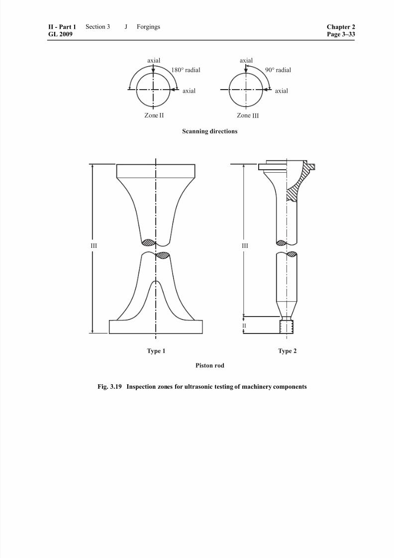
8/10/2019 Casting Material for Shipyards Etc
http://slidepdf.com/reader/full/casting-material-for-shipyards-etc 89/150

8/10/2019 Casting Material for Shipyards Etc
http://slidepdf.com/reader/full/casting-material-for-shipyards-etc 90/150
Fig. 3.20 Inspection zones for ultrasonic testing of machinery components
Chapter 2Page 3–34
Section 3 Forgings II - Part 1GL 2009
J
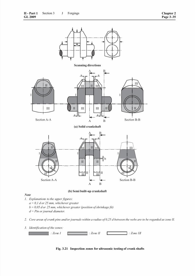
8/10/2019 Casting Material for Shipyards Etc
http://slidepdf.com/reader/full/casting-material-for-shipyards-etc 91/150
Fig. 3.21 Inspection zones for ultrasonic testing of crank shafts
II - Part 1GL 2009
Section 3 Forgings Chapter 2Page 3–35
J

8/10/2019 Casting Material for Shipyards Etc
http://slidepdf.com/reader/full/casting-material-for-shipyards-etc 92/150
8/10/2019 Casting Material for Shipyards Etc
http://slidepdf.com/reader/full/casting-material-for-shipyards-etc 93/150
Section 4
Cast Steel
A. General Rules
1. Scope
This Part contains general rules to be applied in themanufacture and testing of steel castings. Also appli-cable are Chapter 1 – Principles and Test Procedures,Sections 1 – 3.
2. Selection of grades of cast steel
2.1 All cast steel shall be suitable for the in-tended application and shall satisfy the minimumrequirements specified in the following individualRules. Subject to these conditions, grades of cast steelconforming to the relevant standards or to the materialspecifications approved by GL may be used.
2.2 The grades of cast steel shall be identified bythe standardized designations or the designationsgiven in the specifications.
3. Requirements to be met by foundries
3.1 Foundries wishing to supply castings in ac-cordance with these Rules shall be approved by GL.This is conditional upon their fulfilling the manufac-turing and quality control requirements stated in Chap-ter 1 – Principles and Test Procedures, Section 1, C. and furnishing proof of this to GL prior to the com-mencement of supplies.
3.2 Irrespective of the requirements stated in 3.1,the manufacturer shall demonstrate by approval testscarried out on the products that these can be manufac-tured in accordance with the conditions imposed. Thescope of these tests will be determined by GL.
4. Method of manufacture
4.1 Cast steel shall be produced in an electricfurnace, by a basic oxygen process, in an inductionfurnace or by other methods approved by GL. Onrequest, the steel-making process shall be madeknown to GL for approval.
4.2 Where castings are produced by weldingtogether two or more separate components, details ofthe method shall be submitted for approval. This nor-mally calls for a test of the welding procedure.
5. Condition of supply, heat treatment
5.1 All castings shall undergo heat treatmentappropriate to the material. The heat treatments shall
be performed in suitable furnaces. The dimensions ofthe furnace shall enable the entire casting to be raiseduniformly to the required heat treatment temperature.Where, in the case of large castings, the size of thefurnace does not allow the entire casting to be normal-ized at once, other arrangements shall be agreed with
GL.
5.2 Where, following final heat treatment, a cast-ing is heated locally or undergoes hot or cold straight-ening, subsequent stress relief heat treatment may berequired to remove residual stresses.
5.3 Flame cutting, flame scarfing or flame goug-ing to remove excess material or feeders shall be car-ried out by a recognized method prior to final heattreatment. Preheating shall be applied where thechemical composition and/or the thickness of thecasting make this necessary. Where required, the heat-
affected zones of the casting shall be machined orground off.
6. General characteristics of castings
6.1 All castings shall have a clean surface com- patible with the conditions of manufacture. Minorcasting defects such as small sand and slag marks,small cold shuts and small scabs may be trimmed offwithin the negative tolerance on the wall thickness.
6.2 Defects liable to impair the use and workabil-ity of the material to a more than minor degree are not
allowed. They may be removed by one of the methodsnamed in 13.
7. Dimensions; dimensional and geometricaltolerances
The dimensions and the dimensional and geometricaltolerances are governed by the values specified in thedrawings relating to the order or in the relevant stan-dards, as applicable. Appropriate details shall be madeknown to the Surveyor.
8. Tightness
All castings which are subjected to internal pressure by the operating medium or for which special proof ofimpermeability is required shall be leakproof at thespecified test pressures after being machined.
II - Part 1GL 2009
Section 4 Cast Steel Chapter 2Page 4–1
A

8/10/2019 Casting Material for Shipyards Etc
http://slidepdf.com/reader/full/casting-material-for-shipyards-etc 94/150
9. General requirements applicable to castmaterials
9.1 Chemical composition
The chemical composition of grades of cast materialsshall conform to limit values specified in the Tablescontained in this Section and/or in the relevant stan-dards or specifications, as applicable. The manufac-turer shall take suitable measures to ensure that theresidual elements remain within the permitted limits.
9.2 Mechanical properties
9.2.1 Tensile test
The tensile characteristics indicated in the Tablescontained in this Section or, where applicable, in therelevant standards or specifications shall be verified
by tensile test.
9.2.2 Notch bar impact test
The impact energy specified for the various grades ofcast steel shall be satisfied by the average value meas-ured on 3 Charpy V-notch or Charpy U-notch testspecimens, one of which may give a result below therequired average value although it may not be lessthan 70 % of the required average value.
9.3 Other characteristics
Where special characteristics are specified for particu-lar grades of cast steel, e. g. resistance to intercrystal-
line corrosion and mechanical characteristics at ele-vated temperatures, these shall, where necessary, be
proved by appropriate tests.
10. Testing
10.1 Testing of chemical composition
The manufacturer shall determine the chemical com- position of each heat or, where necessary, of eachladle and shall present corresponding certificates tothe Surveyor.
Should there be any doubt as to the chemical composi-
tion of the products, a product analysis shall be per-formed.
10.2 Testing of the mechanical properties andthe selection of specimens
10.2.1 The mechanical properties shall be ascer-tained by tensile test to determine tensile strength,yield strength or 0,2 % proof stress, reduction in areaand elongation.
The notched bar impact test shall also be performedwhere specified for particular grades of cast steel.
10.2.2 The tests shall be performed on a heat-by-heat basis. Castings from each heat that undergo thesame heat treatment shall be grouped into test batchesof up to 4 500 kg. Residual quantities of up to
1 250 kg shall be allocated to the preceding test batch.Parts with unit weights > 1 000 kg shall be testedindividually.
If the finished weight exceeds 10 000 kg, at least two
test specimens shall be taken. For this purpose, testsamples spaced as widely as possible shall be castintegrally with the casting.
10.2.3 For each casting or for each test batch, asapplicable, a sufficient number of samples shall be
provided which shall normally be cast integrally withthe cast component. The number of samples shall besufficient to provide material for the test specimensneeded for possible retests. The sample may only beremoved from the casting after the final heat treat-ment. The thickness of the sample shall be matched tothe relevant wall thickness of the casting, but shall be
at least 30 mm. In the case of thick-walled steel cast-ings, the sample thickness need not exceed 100 mm.
10.2.4 Where a number of small castings of ap- proximately the same dimensions are produced fromthe same heat and are heat treated in the same furnacecharge, then, notwithstanding the provisions stated in10.2.3, specimens may be taken from separately castsamples. For this purpose, at least one sample perfurnace charge shall be provided, which shall be heattreated together with the castings to which it relates.
10.2.5 If separately cast samples are used, these
shall be cast in moulds made of the same mouldingmaterial as that used for the castings themselves.
10.2.6 All samples shall be marked in such a waythat they can be clearly related to the castings whichthey represent. The type of marking shall be agreedwith the Surveyor.
10.2.7 Where castings are manufactured by amethod subject to the special approval of GL, see 4.1, the number and position of the samples shall be spe-cially agreed so as to take account of the method ofmanufacture.
10.3 Testing of surface finish and dimensions
10.3.1 All castings shall be inspected by the manu-facturer for surface finish and compliance with thedimensional and geometrical tolerances and shall then
be presented to the Surveyor for final inspection. In-side surfaces are to be included in the inspection.
10.3.2 The surface of the castings shall be free frommaterial from the mould and shall be properly pre-
pared for inspection. Where necessary, this conditions
shall be achieved by pickling, local grinding, shot orsand blasting, cleaning with wire brushes or by chemi-cal means. Chipping and hammering are allowed onlyif this does not conceal surface defects.
Chapter 2Page 4–2
Section 4 Cast Steel II - Part 1GL 2009
A

8/10/2019 Casting Material for Shipyards Etc
http://slidepdf.com/reader/full/casting-material-for-shipyards-etc 95/150
10.3.3 Where there is reasonable suspicion thatwelds have been carried out on a casting, the Surveyormay require certain areas of the surface to be etched inorder to reveal possible welds.
10.4 Non-destructive tests
10.4.1 Where non-destructive tests are required,these shall be performed by the manufacturer of thecastings and/or the finishing plant. Tests may also bearranged by GL.
10.4.2 Non-destructive tests shall be performed inaccordance with the specifications stated in G. to J. inconsideration of the specifications in Chapter 1 – Principles and Test Procedures, Section 3.
10.5 Retests in the event of failure
If tensile test specimens fail to meet the required val-ues under test, if the specified average value is notachieved in a notched bar impact test or if an individ-ual value is less than 70 % of the required averagevalue, then, before the unit test quantity or the castingis rejected, the procedures for retests prescribed inChapter 1 – Principles and Test Procedures, Section 2,H. may be applied. The additional test specimens shall
be taken either from the same test sample as the origi-nal specimen or from other samples which are repre-sentative of the casting or of the unit test quantity.
11. Identification and marking of castings
11.1 The manufacturer shall institute a monitoringsystem enabling all castings to be traced back to theoriginal heat, and this shall be demonstrated to theSurveyor on request.
11.2 Prior to final inspection, all castings shall be provided by the manufacturer in at least one placewith the following marks:
– cast steel grade
– manufacturer's mark
– heat number, casting number, casting date or anabbreviated symbol enabling the manufacturing
process to be traced
– specimen number
– date of test
– test pressure, where applicable
11.3 In the case of series-manufactured castings,agreement may be reached with the Surveyor to applymarks other than those specified in 11.2.
12. CertificatesFor each consignment the manufacturer shall supply tothe Surveyor a certificate or delivery specificationcontaining at least the following details:
– purchaser and order number
– newbuilding and project number, as applicable,
if known
– nature of castings and grade of cast steel
– purpose and drawing number, if necessary
– item numbers and numbers of units
– weight of delivery
– method of manufacture
– heat numbers
– chemical composition
– condition of supply
– details of heat treatment
– test pressures, where applicable
– results of the mechanical tests
– results of any special tests applied, e.g. non-
destructive tests and test of resistance to inter-
crystalline corrosion
– condition of surface
13. Repair of defects
13.1 Methods
Defects may be repaired by machining, grinding,flame scarfing or gouging, or by welding. The methodis to be agreed with the Surveyor except where theapproval of the Head Office of GL is required for thewelding of highly stressed castings, e.g. diesel engine
parts and turbine casings.
13.2 Machining and grinding
The repair shall be performed in such a way as toremove the defect completely and provide a gradualtransition between the resulting depression and thecontour of the casting. The transition shall be 2 to 3
times the depression. The depth of the repair may nothave more than an insignificant effect on the strengthof the component and the wall thickness shall not bereduced below the minimum tolerance.
13.3 Flame scarfing and gouging
Defects may be removed by flame scarfing and goug-ing. Cast materials liable to hardening shall be appro-
priately preheated. The depressions caused by the re-moval of metal shall afterwards be bright ground. The
grinding shall be sufficiently thorough to ensure the
removal of any metal with a heat-affected structure.
13.4 Fabrication welding
13.4.1 If major defects have to be welded on steelcastings the details of the proposed welding method
II - Part 1GL 2009
Section 4 Cast Steel Chapter 2Page 4–3
A
8/10/2019 Casting Material for Shipyards Etc
http://slidepdf.com/reader/full/casting-material-for-shipyards-etc 96/150
are to be submitted to GL by means of WPS 1 forapproval. The latter shall be amended with sketches or
photographs showing the location of major defectswhich impair the mechanical strength.
For the purpose of these Rules, the term "major de-
fect" includes any defects, the depth of which exceeds
25 % of the wall thickness or 2,5 cm, the area of which
exceeds 1 250 cm2, and those which due to theiramout and distribuition exceed an area of 2 % of the
casting surface.
The characteristics of the weld shall be verified bywelding procedure tests. These are to be performed ontest pieces according to Chapter 5 – Materials forPropeller Fabrication, Annex B, using filler metals ap-
proved by GL. Welding procedure tests and welder’squalification tests respectively which have been per-formed by means of above mentioned test pieces re-
main valid for 3 years and cover thicknesses up to 1,5"t", with "t" being the thickness of the test piece.
In the case of minor repairs, the decision as to theexecution of the repair shall rest with the Surveyor,and the method shall be agreed with him.
It is a basic principle that the welding of major defectsmay only be started after authorization has beengranted and the castings have been presented to theSurveyor in the condition prepared for welding.
13.4.2 Companies wishing to carry out fabricationwelds on castings shall have available the necessaryworkshops, lifting gear, welding appliances, preheat-ing and heat treatment facilities, testing instrumentsand equipment as well as qualified welders and com-
petent welding supervisors so that the work can be properly executed. As a preliminary measure, compli-ance with these conditions shall be proved to GL and adescription of the welding facilities and proceduresshall be submitted.
13.4.3 The following conditions shall be compliedwith in carrying out welding work:
– Highly stressed parts and alloy steel castingsshall be in the prescribed heat-treated conditionfor welding. This also applies to other castingson which major defects have to be repaired.
– Defects are to be gouged out in such a way as to provide good accessibility for welding. Having been prepared for welding, the sites concernedshall be subjected to non-destructive tests to es-tablish that the defective material has been com-
pletely removed. The castings prepared forwelding are to be submitted to the Surveyor.
– Steel castings shall be suitably preheated forwelding. The level of preheating shall be deter-mined in each case by reference to the chemicalcomposition, the carbon equivalent and the wall
thickness, see B.4.1.4. Exceptions to this Rule
––––––––––––––1 WPS = Welding Procedure Specification
are austenitic grades of cast steel and, with theconsent of the Surveyor, unalloyed grades ofcast steel of small wall thickness which because
of their composition (C ≤ 0,18 %) are consid-ered to be unsusceptible to cracking.
– All welding work is to be performed by quali-fied welders, whose work is supervised while in
progress, in bays which are protected fromdraughts and the effects of the weather. Wher-ever feasible, welding shall be performed in thedownhand position.
– The filler materials to be used shall produce aweld deposit with mechanical characteristicsmatching those of the casting. In the case ofstainless grades of cast steel, the deposit shallensure the sufficient chemical stability of theweld. Wherever possible the work shall be per-
formed by manual arc welding using basic-coated electrodes with a controlled, low hydro-gen content.
– After welding, the castings shall be properlyheat treated as follows:
– unalloyed steel castings: stress relief heattreatment in temperature range 580 – 620 °C,or renewed normalizing treatment
– quenched and tempered steel castings: re-newed tempering or quenching and temper-ing
– ferritic stainless steel and all grades of aus-tenitic steel castings: the heat treatment pre-scribed in the relevant standard or recog-nized material specification, as applicable.
– Attention shall be paid to the effect of the heattreatment on the mechanical properties of theweld metal.
– Following welding and heat treatment, the weldsand their surrounding areas are to be groundsmooth and inspected by the magnetic particleor dye penetrant method. Depending on the na-ture and size of the original defect, further non-
destructive testing by ultrasonic or radiographicinspection may be required. For the evaluationof the indications 10.4.2 is applicable.
13.4.4 After repair and subsequent heat treatment,all castings shall be presented to the Surveyor forreinspection, and the tests for cracks and the ultrasonictests shall be performed wholly or partly in the Sur-veyor's presence at his discretion. In the case of radio-graphic tests, the radiographs shall be submitted to theSurveyor for expert appraisal.
13.4.5 For large welds on highly stressed or alloy
steel castings, the manufacturer shall hand the Sur-
veyor a report containing full details of the repair, in-cluding the results of the non-destructive tests. In this
report he shall also confirm that the weld has been made
in accordance with an approved welding procedure.
Chapter 2Page 4–4
Section 4 Cast Steel II - Part 1GL 2009
A
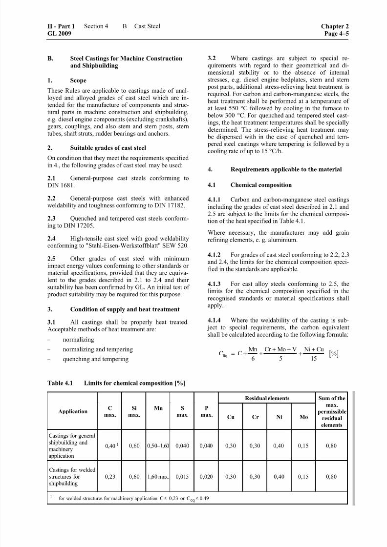
8/10/2019 Casting Material for Shipyards Etc
http://slidepdf.com/reader/full/casting-material-for-shipyards-etc 97/150
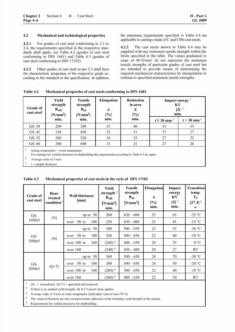
8/10/2019 Casting Material for Shipyards Etc
http://slidepdf.com/reader/full/casting-material-for-shipyards-etc 98/150
4.2 Mechanical and technological properties
4.2.1 For grades of cast steel conforming to 2.1 to2.4, the requirements specified in the respective stan-dards shall apply, see Table 4.2 (grades of cast steel
conforming to DIN 1681) and Table 4.3 (grades ofcast steel conforming to DIN 17182).
4.2.2 Other grades of cast steel as per 2.5 shall have
the characteristic properties of the respective grade ac-cording to the standard or the specification. In addition,
the minimum requirements specified in Table 4.4 are
applicable to castings made of C and CMn cast steels.
4.2.3 The cast steels shown in Table 4.4 may besupplied with any minimum tensile strength within thelimits specified in the table. The values graduated in
steps of 40 N/mm2 do not represent the minimumtensile strengths of particular grades of cast steel butare intended to provide means of determining therequired mechanical characteristics by interpolation inrelation to specified minimum tensile strengths.
Table 4.2 Mechanical properties of cast steels conforming to DIN 1681
Impact energy 1
KV
[J] 2
min.
Grade of
cast steel
Yield
strength
R eH
[N/mm2
]min.
Tensile
strength
R m
[N/mm2
]min.
Elongation
A
[%]min.
Reduction
in area
Z
[%]min. t 30 mm 3 t > 30 mm 3
GS–38 200 380 25 40 35 35
GS–45 230 450 22 31 27 27
GS–52 260 520 18 25 27 22
GS–60 300 600 15 21 27 20
1 testing temperature = room temperature
For castings for welded structures in shipbuilding the requirements according to Table 4.3 do apply.
2 Average value of 3 tests
3 t = sample thickness
Table 4.3 Mechanical properties of cast steels in the style of DIN 17182
Grade ofcast steel
Heat-treated
condition 1
Wall thickness[mm]
Yieldstrength 2
R eH
[N/mm2]min.
Tensilestrength
R m[N/mm2]
Elongation
A
[%]min.
Impactenergy
KV[J] 3
min.
Transitiontemp.
TÜ
[27 J] 5 ≈
up to 50 260 430 – 600 25 65 –25 °CGS-16Mn5
(N)over 50 to 100 230 430 – 600 25 45 –15 °C
up to 50 300 500 – 650 22 55 –20 °C
over 50 to 100 260 500 – 650 22 40 –10 °C
over 100 to 160 (260) 4 480 – 630 20 35 0 °C
GS-
20Mn5(N)
over 160 (240) 4 450 – 600 20 27 RT
up to 50 360 500 – 650 24 70 –30 °C
over 50 to 100 300 500 – 650 24 50 –20 °C
over 100 to 160 (280) 4 500 – 650 22 40 –10 °C
GS-20Mn5
(Q+T)
over 160 (260) 4 480 – 630 22 30 RT
1 (N) = normalized; (Q+T) = quenched and tempered
2 If there is no marked yield strength, the 0,2 % proof stress applies.
3 Average value of 3 tests at room temperature (individual value at least 70 %).4 The values in brackets are only an approximate indication of the minimum yield strength in the casting.
5 Requirements for welded structures for shipbuilding.
Chapter 2Page 4–6
Section 4 Cast Steel II - Part 1GL 2009
B
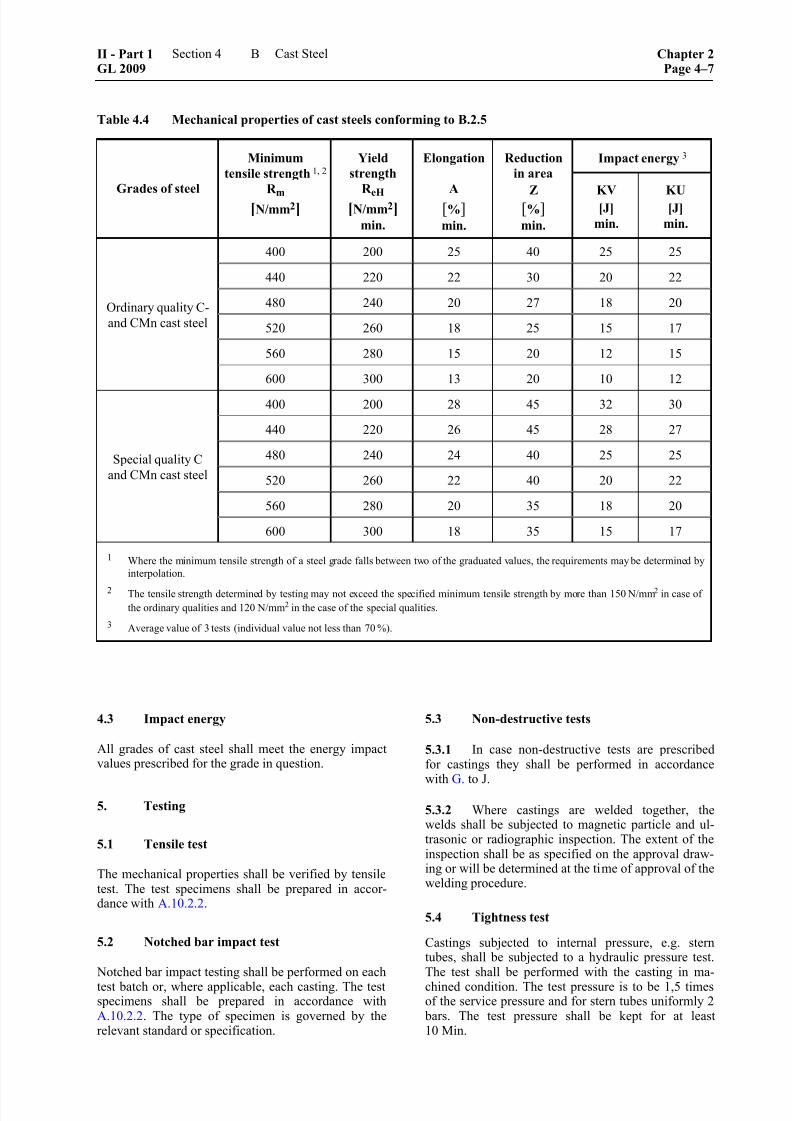
8/10/2019 Casting Material for Shipyards Etc
http://slidepdf.com/reader/full/casting-material-for-shipyards-etc 99/150
8/10/2019 Casting Material for Shipyards Etc
http://slidepdf.com/reader/full/casting-material-for-shipyards-etc 100/150
C. Steel Castings for Crankshafts and Con-necting Rods
1. Scope
These Rules are applicable to throws and webs of builtcrankshafts and connecting rods made of carbon, car-
bon-manganese and low-alloy grades of cast steel.
2. Approved grades of cast steel
Only grades of cast steel which have been approved by GL as suitable for the intended application may beused. To this end, the engine manufacturer shall sub-mit to GL for approval specifications or drawingscontaining all the data required for evaluating thecastings, e.g. method of manufacture, chemical com-
position, heat treatment and mechanical properties.
3. Requirements applicable to the material
3.1 With regard to the chemical composition,mechanical properties and required impact energy andhardness values, the data in the approved specifica-tions or drawings are applicable. However, the re-quirements specified in B.2.5 and, for special qualitysteel castings, Table 4.4 are to be satisfied as a mini-mum requirement.
3.2 The cast steel shall undergo vacuum degas-sing or another suitable treatment after melting, so thatthe properties mentioned in the specification may beachieved.
4. Method of manufacture and condition of
heat treatment
4.1 The method of manufacture shall be ap- proved by GL. The details of the approval test areestablished by GL from case to case.
4.2 All castings shall be in a heat treated condi-tion appropriate to the grade of steel. The following
processes are acceptable:
– normalizing
– normalizing and tempering
– quenching and tempering
Where possible, heat treatment shall be carried outafter preliminary machining. If this is not possible,additional stress-relieving heat treatment shall be
performed after preliminary machining with theminimum possible cutting allowance.
4.3 Defects shall normally be removed by grind-ing, gouging and/or machining. Care shall be taken toensure that the required minimum cross sections are
preserved.
The removal of defects by welding requires the con-sent of GL as a matter of principle and may only beconsidered if the defects cannot be eliminated by theaforementioned measures.
5. Testing
5.1 Tensile test
The mechanical properties shall be verified by tensile
test. For preparing the tensile specimens, test samplesshall be cast integrally with the casting at a pointstipulated in the specification. Each casting shall betested individually.
5.2 Notched bar impact test
Notched bar impact specimens shall be taken fromevery casting and tested. The location of the speci-mens shall be as described in 5.1. The specimen shape
prescribed in the specification (Charpy V-notch orCharpy U-notch specimen) shall be used.
5.3 Non-destructive tests
Crank shafts and connecting rods shall be subjected tonon-destructive tests according to the requirementsstipulated in G. to J.
By agreement between the foundry and the crankshaftor connecting rod manufacturer, the tests may be per-formed both at the foundry and at the manufacturer'sworks.
D. Steel Castings for Steam Boilers, Pressure
Vessels and Pipelines
1. Scope
1.1 These Rules are applicable to castings madefrom unalloyed and alloyed grades of cast steel andused for the manufacture of valve and pump housings,endplates, flanges, nozzles and pipe fittings. Caststeels for use at low temperatures are subject to E.
2. Suitable grades of cast steel
The following grades of cast steel may be used:
2.1 Grades of cast steel for use at room tempera-ture and high temperatures conforming to EN 10213-2"Technical Specifications relating to Cast Steel forPressure Vessels", Part 2.
The chemical composition of the commonly usedgrades of cast steel is given in Table 4.5 and the me-chanical properties are stated in Table 4.6.
2.2 Ferritic grades of cast steel GS–38 and GS– 45 conforming to DIN 1681 up to a wall temperatureof 300 °C.
2.3 Heat resistant ferritic, ferritic-austenitic andaustenitic grades of cast steel as well as Nickel andcobalt based alloys conforming to EN 10295.
Chapter 2Page 4–8
Section 4 Cast Steel II - Part 1GL 2009
D

8/10/2019 Casting Material for Shipyards Etc
http://slidepdf.com/reader/full/casting-material-for-shipyards-etc 101/150
Table 4.5 Chemical composition (%) of the commonly used grades of cast steel conforming to EN 10213-2
Grade of
cast steelC
Si
max.Mn
P
max.
S
max.Cr Mo
GP240GH 0,18 – 0,23 0,60 0,50 – 1,20 0,030 0,020 1 –– ––
GP280GH 0,18 – 0,25 2 0,60 0,80 – 1,20 2 0,030 0,020 1 –– ––
G20Mo5 0,15 – 0,23 0,60 0,50 – 1,00 0,025 0,020 1 –– 0,40 – 0,60
G17CrMo5-5 0,15 – 0,20 0,60 0,50 – 1,00 0,020 0,020 1 1,00 – 1,50 0,45 – 0,65
G17CrMo9-10 0,13 – 0,20 0,60 0,50 – 0,90 0,020 0,020 1 2,00 – 2,50 0,90 – 1,20
1 In the case of castings having a standard wall thickness of < 28 mm, 0,030 % is permissible.
2 For each 0,01 % reduction in the specified maximum carbon content, a 0,04 % increase of Manganese above the specified maximum
content is permissible up to a maximum of 1,40 %.
Table 4.6 Mechanical properties of the commonly used grades of cast steel conforming to EN 10213-2
Tensile testNotched bar
impact test Grade of
cast steel
Heat
treatment
symbol 1
Thickness
[mm]
max. R p0,2
[N/mm2]
min.
R m
[N/mm2]
A
[%]
min.
KV 2
[J]
min.
N 27GP240GH
QT
100 240 420 – 600 22
40
N 27GP280GH
QT100 280 480 – 640 22
35
G20Mo5 QT 100 245 440 – 590 22 27
G17CrMo5-5 QT 100 315 490 – 690 20 27
G17CrMo9-10 QT 100 400 590 – 740 18 40
1 N = denotes normalising
QT = denotes quenching and tempering
2 Testing temperature = room temperature (individual value not less than 70 %)
2.4 Other grades of cast steel conforming to other standards or material specifications, provided that they
are comparable with the grades of cast steel stated in
paragraphs 2.1 to 2.3 and proof has been furnished of their suitability for the intended application. An initial test of product suitability may be required for this pur-
pose.
2.4.1 In addition, ferritic grades of cast steel shall
satisfy the following minimum requirements: – The elongation A shall have the characteristic
minimum elongation values of the steel grade asspecified by GL, but shall be not less than 15 %.
– The impact energy shall be at least 27 J at roomtemperature in tests performed with Charpy V-notch specimens. Ductile fracture behaviour is afundamental requirement.
– Where necessary, the yield strength at elevatedtemperature and the long-time rupture stress
properties at elevated temperature shall be veri-fied by the manufacturer, specifying the guide
values for the chemical composition.
Proof of weldability shall be furnished by the manu-facturer.
II - Part 1GL 2009
Section 4 Cast Steel Chapter 2Page 4–9
D
8/10/2019 Casting Material for Shipyards Etc
http://slidepdf.com/reader/full/casting-material-for-shipyards-etc 102/150
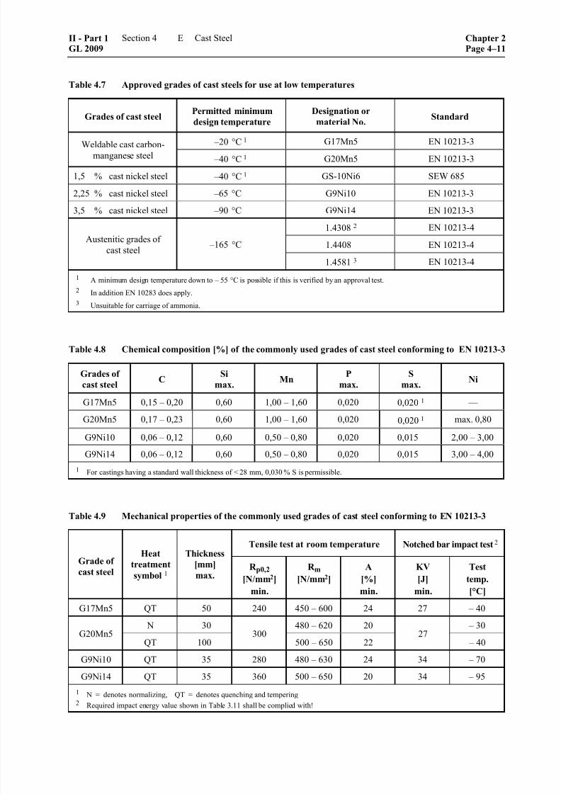
8/10/2019 Casting Material for Shipyards Etc
http://slidepdf.com/reader/full/casting-material-for-shipyards-etc 103/150
Table 4.7 Approved grades of cast steels for use at low temperatures
Grades of cast steel Permitted minimum
design temperature
Designation or
material No. Standard
–20 °C 1 G17Mn5 EN 10213-3Weldable cast carbon-
manganese steel –40 °C 1 G20Mn5 EN 10213-3
1,5 % cast nickel steel –40 °C 1 GS-10Ni6 SEW 685
2,25 % cast nickel steel –65 °C G9Ni10 EN 10213-3
3,5 % cast nickel steel –90 °C G9Ni14 EN 10213-3
1.4308 2 EN 10213-4
1.4408 EN 10213-4Austenitic grades of
cast steel –165 °C
1.4581 3 EN 10213-4
1 A minimum design temperature down to – 55 °C is possible if this is verified by an approval test.
2 In addition EN 10283 does apply.
3 Unsuitable for carriage of ammonia.
Table 4.8 Chemical composition [%] of the commonly used grades of cast steel conforming to EN 10213-3
Grades of
cast steelC
Si
max.Mn
P
max.
S
max.Ni
G17Mn5 0,15 – 0,20 0,60 1,00 – 1,60 0,020 0,020 1 ––
G20Mn5 0,17 – 0,23 0,60 1,00 – 1,60 0,020 0,020 1 max. 0,80
G9Ni10 0,06 – 0,12 0,60 0,50 – 0,80 0,020 0,015 2,00 – 3,00
G9Ni14 0,06 – 0,12 0,60 0,50 – 0,80 0,020 0,015 3,00 – 4,00
1 For castings having a standard wall thickness of < 28 mm, 0,030 % S is permissible.
Table 4.9 Mechanical properties of the commonly used grades of cast steel conforming to EN 10213-3
Tensile test at room temperature Notched bar impact test 2
Grade of
cast steel
Heattreatment
symbol 1
Thickness[mm]
max.R p0,2
[N/mm2]
min.
R m[N/mm2]
A
[%]
min.
KV
[J]
min.
Test
temp.
[°C]
G17Mn5 QT 50 240 450 – 600 24 27 – 40
N 30 480 – 620 20 – 30G20Mn5
QT 100300
500 – 650 2227
– 40
G9Ni10 QT 35 280 480 – 630 24 34 – 70
G9Ni14 QT 35 360 500 – 650 20 34 – 95
1 N = denotes normalizing, QT = denotes quenching and tempering
2 Required impact energy value shown in Table 3.11 shall be complied with!
II - Part 1GL 2009
Section 4 Cast Steel Chapter 2Page 4–11
E

8/10/2019 Casting Material for Shipyards Etc
http://slidepdf.com/reader/full/casting-material-for-shipyards-etc 104/150
4. External and internal condition
The external and internal condition shall be subject toquality levels in accordance with Table 4.10 depend-ing on the minimum design temperature.
If the evaluation is carried out according to other stan-dards, the requirements shall be equivalent to thosespecified in Table 4.10.
If castings are required to undergo final inspection inaccordance with the AD data sheets, proof of the qual-ity levels and scopes of testing is to be furnished inaccordance with these Rules.
Table 4.10 Assignment of quality levels
Minimum designtemperature
t
Quality levelaccording to:
1, 2, 3, 4
≥ –105 °C
SM4, LM4, AM4 1,
SP4, CP3, LP4, AP4 2,
UV4 3, RV4 4
< –105 °C
SM3, LM3, AM3 1,
SP3, CP3, LP3, AP3 2,
UV3 3, RV3 4
Welding edges 5 SM011
CP01 2
1 EN 13692 EN 1371-1
3 EN 12680-24 EN 12681 and former DIN 1690-25 For surface crack detection linear indications are not
allowed.
5. Requirements applicable to the material
5.1 General requirements
The chemical composition and the mechanical proper-ties are subject to the requirements specified in thestandards or the approved specifications (see Tables
4.8 and 4.9).
5.2 Weldability
Grades of cast steel conforming to these rules shall beweldable by established workshop methods.
5.3 Impact energy at low temperatures
The required impact energy values specified in Table4.11 for the relevant grades of cast steel shall be metat the test temperatures stated in the table, usingCharpy V-notch specimens.
6. TestingThe castings shall be presented for testing in finishedcondition (condition of supply) and shall undergo thefollowing tests.
Table 4.11 Required impact energy values atlow temperatures
Notched bar
impact test
Grade of cast steel Test
temp.
[°C]
Impact
energy
KV
[J] 1
min.
Weldable cast carbon
manganese steel27 (19)
1,5 % cast nickel steel
5 K below
minimum
design
temp.,
not
exceeding
–20 °C 34 (24)
2,25 % cast nickel steel –70 °C 34 (24)
3,5 % cast nickel steel –95 °C 34 (24)
Austenitic grades
of cast steel 2 –196 °C 41 (27) 3
1 Average value for 3 specimens. Figures in parentheses
indicate lowest individual value.2 For design temperatures of – 105 °C and above, verification
of the impact energy may be dispensed with.3 Some austenitic grades of cast steel are subject to higher
required impact energy values, see Table 4.13, Part F.
6.1 Tensile test
The mechanical properties shall be verified by tensiletest. The tests shall be performed on a heat-by-heat
basis, parts undergoing the same heat treatment beinggrouped into test batches in accordance with A.10.2.2. A tensile specimen shall be taken from each test batchand tested. Castings with unit weights > 1 000 kg shall
be tested individually.
6.2 Notched bar impact test
The castings shall be subjected to the notched bar
impact test in compliance with the prescribed testtemperature according to Table 4.11. The number ofsets of test specimens (3 Charpy V-notch specimens
per set) shall be determined in the same way as thenumber of tensile specimens.
The test may be dispensed with in the case of austenitic
steel castings with design temperatures of ≥ 105°C.
6.3 Hardness test
All quenched and tempered steel castings which aretested on a heat-by-heat basis shall be subjected to acomparative hardness test. The result of the hardness
test shall show that quenching and tempering has beencarried out homogeneously (the difference in hardness
between the hardest and the softest tested componentin the test batch shall not exceed 30 HB).
Chapter 2Page 4–12
Section 4 Cast Steel II - Part 1GL 2009
E

8/10/2019 Casting Material for Shipyards Etc
http://slidepdf.com/reader/full/casting-material-for-shipyards-etc 105/150
6.4 Non-destructive testing
The manufacturer shall ensure by non-destructive testson his products that the requirements pertaining to theexternal and internal condition according to 4. are met.Unless otherwise agreed, the scope of testing shallconform to AD data sheet W5; valves and fittings aresubject to AD data sheet AD-W10. In addition theRules as stated in Chapter 1 – Principles and TestProcedures, Section 3 shall be observed.
F. Stainless Steel Castings
1. Scope
These Rules are applicable to steel castings made fromaustenitic and austenitic-ferritic grades of steel which
are intended for use in cargo and processing equip-ment for chemical tankers and other equipment forwhich chemical stability in relation to the cargo or theoperating fluid is required. These Rules also apply tosleeves and bushes for propeller shafts and rudderstocks.
The Rules are also applicable in conjunction with E.for austenitic grades of cast steel which are designedfor use in cargo and processing systems for gas tank-ers.
2. Suitable grades of cast steel
The following grades of casting may be used, pro-vided that they satisfy the requirements stated in 6.
2.1 Austenitic and austenitic-ferritic grades ofsteel conforming to EN 10213-4, "Technical Specifi-cations relating to Cast Steel for use in pressure Ves-sels" as well as the grades indicated in EN 10283,Corrosion resistant steel castings. The chemical com-
position of these grades of cast steel is shown in Table4.12 and the mechanical properties are given in Table4.13.
2.2 Other stainless steels conforming to other
standards or specifications after their suitability has been established by GL. An initial test of productsuitability on the manufacturer's premises may berequired for this purpose.
3. Selection of grades of cast steel
As regards their chemical resistance, the grades ofsteel shall be selected in accordance with the opera-tor's list of substances, which provides information onthe nature of the substances to be transported orstored.
3.1 Where austenitic grades of cast steel are in-
tended for cargo and process equipment for gas tank-ers, the requirements applicable to castings as stated inE., "Steel castings for use at low temperatures" shallapply.
4. Heat treatment and condition of supply
All steel castings shall be supplied in a heat-treatedcondition appropriate to the grade of cast steel, i.e. thegrades specified in Table 4.13 shall be solution-annealed and quenched in water.
5. External and internal condition
Requirements to the external and internal conditionshall be agreed on by the orderer and the manufac-turer. Requirements to welding edges and special rimzones shall be agreed on separately. In case no agree-ments were made G.3. does apply.
6. Requirements applicable to the material
6.1 Chemical composition
6.1.1 The limits stated in Table 4.12 and/or thespecifications approved by GL are applicable.
6.1.2 For steel castings for the cargo and process-ing equipment of chemical tankers, the compositionshall be selected so as to ensure the chemical stabilityrequired for the particular application, having regardto the intended heat-treated condition of the material.Furthermore, where steel castings are to be used forwelded structures, the composition shall be selected soas to ensure that the material is suitable for the pro-
posed welding process and that it remains chemically
stable after welding and any post-weld heat treatmentswhich may be applied. In the case of austenitic andaustenitic-ferritic grades of cast steel, 6.2 shall becomplied with. The manufacturer shall prove theweldability of the material if requested to do so.
6.1.3 If compliance with a minimum value for theaggregate effective chromium value W is required fora particular application, this is calculated as follows:
[ ] [ ] [ ]W % % Cr 3,3 % Mo= + ⋅
Note
This formula is applicable for austenitic cast steelwhich has a molybdenum content of < 3 %.
6.2 Resistance to intercrystalline corrosion
Austenitic grades of cast steel shall be resistant tointercrystalline corrosion in the condition in whichthey are supplied. If it is intended to weld castingswithout post-weld heat treatment, only grades of caststeel that are corrosion-resistant in this condition aswell shall be used, e.g. cast steels stabilized with Nbor containing not more than 0,03 % C.
6.3 Mechanical properties and impact energy
The requirements specified in Table 4.13 or in theapproved specifications are applicable.
II - Part 1GL 2009
Section 4 Cast Steel Chapter 2Page 4–13
F
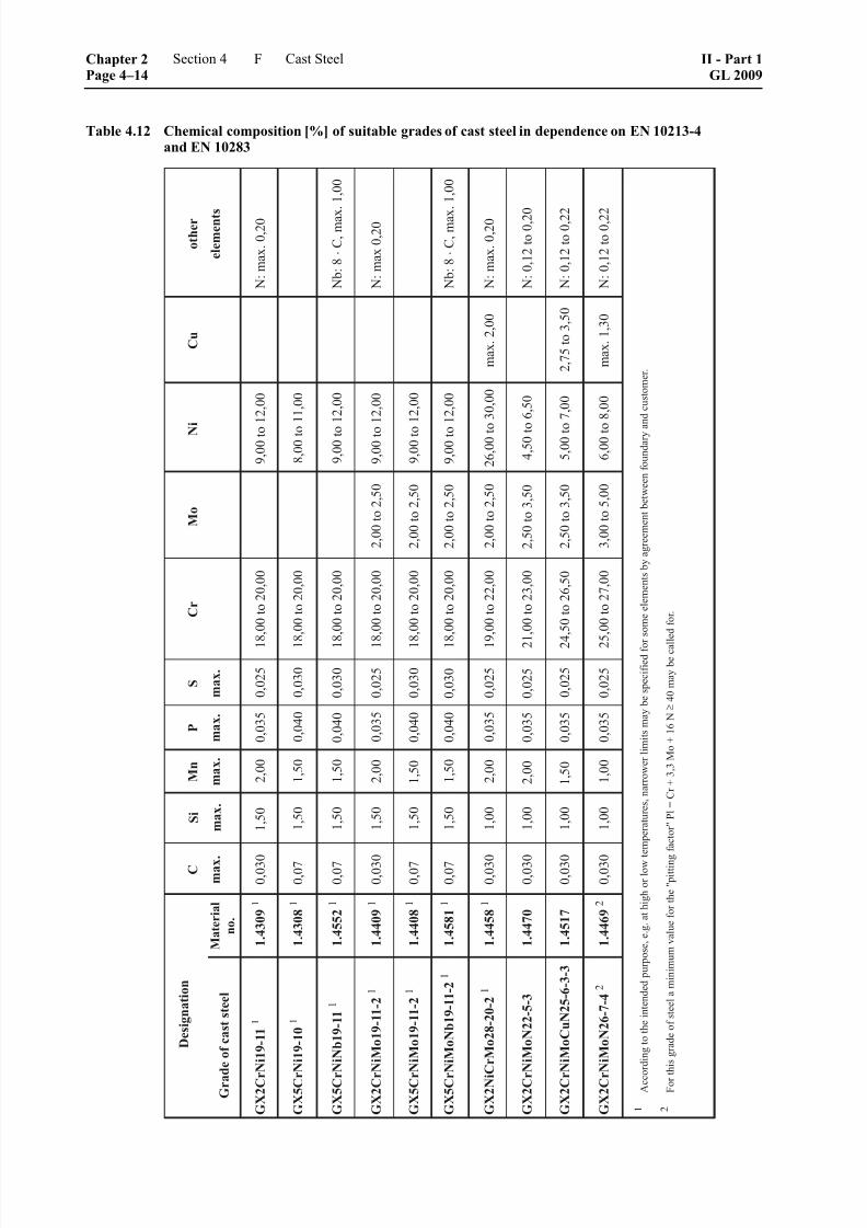
8/10/2019 Casting Material for Shipyards Etc
http://slidepdf.com/reader/full/casting-material-for-shipyards-etc 106/150
Table 4.12 Chemical composition [%] of suitable grades of cast steel in dependence on EN 10213-4and EN 10283
Chapter 2Page 4–14
Section 4 Cast Steel II - Part 1GL 2009
F

8/10/2019 Casting Material for Shipyards Etc
http://slidepdf.com/reader/full/casting-material-for-shipyards-etc 107/150
Table 4.13 Mechanical properties of suitable grades of cast steel
Tensile test at
room temperature
Notched
bar impact
testThick-
ness
[mm] R p1,0 4
[N/mm2]
A[%]
KV 6
[J]
Designation Material No.
Heat treatment
+ AT 1 [°C]
max. min.
R m
[N/mm2]
min. min.
GX2CrNi19-11 1.4309 1050 – 1150 150 210 440 – 640 30 80
GX5CrNi19-10 1.4308 1050 – 1150 150 200 440 – 640 30 60
GX5CrNiNb19-11 1.4552 1050 – 1150 150 200 440 – 640 25 40
GX2CrNiMo19-11-2 1.4409 1080 – 1150 150 220 440 – 440 30 80
GX5CrNiMo19-11-2 1.4408 1080 – 1150 150 210 440 – 640 30 60
GX5CrNiMoNb19-11-2 1.4581 1080 – 1150 150 210 440 – 640 25 40
GX2NiCrMo28-20-2 1.4458 1100 – 1180 150 190 430 – 630 30 60
GX2CrNiMoN22-5-3 1.4470 1120 – 11502, 3 150 420 5 600 – 800 20 30
GX2CrNiMoCuN25-6-3-3 1.4517 1120 – 11502, 3 150 480 5 650 – 850 22 50
GX2CrNiMoN26-7-4 1.4469 1140 – 11802, 3 150 480 5 650 – 850 22 50
1 The heat treatment applicable to all grades of steel is + AT + QW (solution annealing + quenching in water).
2 Following solution annealing at high temperature, the castings may be cooled to between 1 040 °C and 1 010 °C before quenching
in water to improve corrosion resistance and prevent cracks in the event of complex shapes.
3 In the case of cast steel intended for pressure vessels, the precipitation-hardened condition is not applicable to austenitic-ferritic steels.
4 R p0,2 may be estimated by reducing the R p1,0 value by 25 N/mm2.
5 R p0,2
6 Test temperature = room temperature RT (individual value not less than 70 %)
7. Testing
The castings shall be presented for testing in finishedcondition (condition of supply) and shall undergo thefollowing tests:
7.1 Tensile test
The mechanical properties shall be verified by tensiletest. The tests shall be performed on a heat-by-heat
basis, parts undergoing the same heat treatment beinggrouped into test batches in accordance with A.10.2.2. A tensile specimen shall be taken from each test batchand tested. Castings with unit weights > 1000 kg shall
be tested individually.
7.2 Notched bar impact test
The castings shall be subjected to the notched bar
impact test. The number of sets of test specimens (3Charpy V-notch specimens per set) shall be deter-mined in the same way as the number of tensilespecimens.
7.3 Test of resistance to intercrystalline corrosion
Austenitic and austenitic-ferritic steel castings shall betested per heat and heat treatment batch for their resis-
tance to intercrystalline corrosion in accordance withISO 3651-1 or -2. Austenitic-ferritic grades of caststeel shall be tested in accordance with Iron and SteelTest Specification SEP 1877, Method I, or an equiva-lent method. The test shall be confirmed by the manu-facturer by means of a certificate.
7.4 Non-destructive testing
The manufacturer shall ensure by non-destructive testson his products that the requirements pertaining to theexternal and internal condition according to 5. are met.Unless otherwise agreed, the scope of testing shall
conform to AD Data Sheet W5. Valves and fittings aresubject to TRD 110. In addition the Rules as stated inChapter 1 – Principles and Test Procedures, Section 3 shall be observed.
II - Part 1GL 2009
Section 4 Cast Steel Chapter 2Page 4–15
F
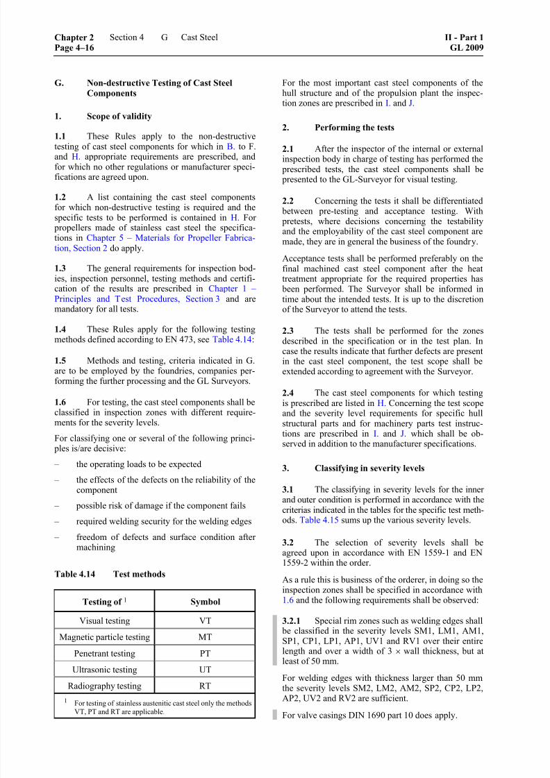
8/10/2019 Casting Material for Shipyards Etc
http://slidepdf.com/reader/full/casting-material-for-shipyards-etc 108/150
G. Non-destructive Testing of Cast Steel
Components
1. Scope of validity
1.1 These Rules apply to the non-destructivetesting of cast steel components for which in B. to F.and H. appropriate requirements are prescribed, andfor which no other regulations or manufacturer speci-fications are agreed upon.
1.2 A list containing the cast steel componentsfor which non-destructive testing is required and thespecific tests to be performed is contained in H. For
propellers made of stainless cast steel the specifica-tions in Chapter 5 – Materials for Propeller Fabrica-tion, Section 2 do apply.
1.3 The general requirements for inspection bod-ies, inspection personnel, testing methods and certifi-cation of the results are prescribed in Chapter 1 –Principles and Test Procedures, Section 3 and aremandatory for all tests.
1.4 These Rules apply for the following testingmethods defined according to EN 473, see Table 4.14:
1.5 Methods and testing, criteria indicated in G.are to be employed by the foundries, companies per-forming the further processing and the GL Surveyors.
1.6 For testing, the cast steel components shall beclassified in inspection zones with different require-ments for the severity levels.
For classifying one or several of the following princi- ples is/are decisive:
– the operating loads to be expected
– the effects of the defects on the reliability of thecomponent
– possible risk of damage if the component fails
– required welding security for the welding edges
– freedom of defects and surface condition after
machining
Table 4.14 Test methods
Testing of 1 Symbol
Visual testing VT
Magnetic particle testing MT
Penetrant testing PT
Ultrasonic testing UT
Radiography testing RT
1 For testing of stainless austenitic cast steel only the methods
VT, PT and RT are applicable.
For the most important cast steel components of thehull structure and of the propulsion plant the inspec-tion zones are prescribed in I. and J.
2. Performing the tests
2.1 After the inspector of the internal or externalinspection body in charge of testing has performed the
prescribed tests, the cast steel components shall be presented to the GL-Surveyor for visual testing.
2.2 Concerning the tests it shall be differentiated between pre-testing and acceptance testing. With pretests, where decisions concerning the testabilityand the employability of the cast steel component aremade, they are in general the business of the foundry.
Acceptance tests shall be performed preferably on the
final machined cast steel component after the heattreatment appropriate for the required properties has been performed. The Surveyor shall be informed intime about the intended tests. It is up to the discretionof the Surveyor to attend the tests.
2.3 The tests shall be performed for the zonesdescribed in the specification or in the test plan. Incase the results indicate that further defects are presentin the cast steel component, the test scope shall beextended according to agreement with the Surveyor.
2.4 The cast steel components for which testingis prescribed are listed in H. Concerning the test scopeand the severity level requirements for specific hullstructural parts and for machinery parts test instruc-tions are prescribed in I. and J. which shall be ob-served in addition to the manufacturer specifications.
3. Classifying in severity levels
3.1 The classifying in severity levels for the inner and outer condition is performed in accordance with the
criterias indicated in the tables for the specific test meth-ods. Table 4.15 sums up the various severity levels.
3.2 The selection of severity levels shall beagreed upon in accordance with EN 1559-1 and EN1559-2 within the order.
As a rule this is business of the orderer, in doing so theinspection zones shall be specified in accordance with1.6 and the following requirements shall be observed:
3.2.1 Special rim zones such as welding edges shall be classified in the severity levels SM1, LM1, AM1,SP1, CP1, LP1, AP1, UV1 and RV1 over their entirelength and over a width of 3 × wall thickness, but atleast of 50 mm.
For welding edges with thickness larger than 50 mmthe severity levels SM2, LM2, AM2, SP2, CP2, LP2,AP2, UV2 and RV2 are sufficient.
For valve casings DIN 1690 part 10 does apply.
Chapter 2Page 4–16
Section 4 Cast Steel II - Part 1GL 2009
G
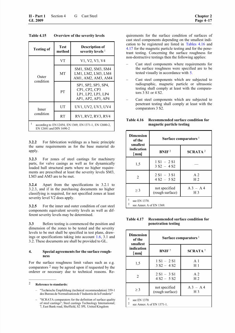
8/10/2019 Casting Material for Shipyards Etc
http://slidepdf.com/reader/full/casting-material-for-shipyards-etc 109/150
Table 4.15 Overview of the severity levels
Testing ofTest
method
Description of
severity levels 1
VT V1, V2, V3, V4
MT
SM1, SM2, SM3, SM4
LM1, LM2, LM3, LM4
AM1, AM2, AM3, AM4Outer
condition
PT
SP1, SP2, SP3, SP4,
CP1, CP2, CP3
LP1, LP2, LP3, LP4AP1, AP2, AP3, AP4
UT UV1, UV2, UV3, UV4Inner
conditionRT RV1, RV2, RV3, RV4
1 according to EN 12454, EN 1369, EN 1371-1, EN 12680-2,
EN 12681 and DIN 1690-2
3.2.2 For fabrication weldings as a basic principlethe same requirements as for the base material doapply.
3.2.3 For zones of steel castings for machinery parts, for valve casings as well as for dynamicallyloaded hull structural parts where no higher require-ments are prescribed at least the severity levels SM3,LM3 and AM3 are to be met.
3.2.4 Apart from the specifications in 3.2.1 to3.2.3, and if in the purchasing documents no higherclassifying is required, for not specified zones at leastseverity level V2 does apply.
3.2.5 For the inner and outer condition of cast steelcomponents equivalent severity levels as well as dif-ferent severity levels may be determined.
3.3 Before testing is commenced the position anddimension of the zones to be tested and the severity
levels to be met shall be specified in test plans, draw-ings or specifications taking into account 1.6, 3.1 and3.2. These documents are shall be provided to GL.
4. Special agreements for the surface rough-ness
For the surface roughness limit values such as e.g.
comparators 2 may be agreed upon if requested by theorderer or necessary due to technical reasons. Re-
––––––––––––––2 Reference to standards:
– "Technische
Empfehlung
(technical
recommendation)
359-1
des Bureau de Normalisation de l' Industrie de la Fonderie"
– "SCRATA comparators for the definition of surface qualityof steel castings"; Steel castings Technology International;7, East Bank road, Sheffield, S2 3PL United Kingdom
quirements for the surface condition of surfaces ofcast steel components depending on the smallest indi-cation to be registered are listed in Tables 4.16 and4.17 for the magnetic particle testing and for the pene-trant testing. Concerning the surface roughness for
non-destructive testings then the following applies: – Cast steel components where requirements for
the surface roughness were specified are to betested visually in accordance with 5.
– Cast steel components which are subjected toradiographic, magnetic particle or ultrasonictesting shall comply at least with the compara-tors 3 S1 or 4 S2.
– Cast steel components which are subjected to penetrant testing shall comply at least with thecomparators 3 S2.
Table 4.16 Recommended surface condition formagnetic particle testing
Surface comparators 1 Dimension
of the
smallest
indication
mm
BNIF 2 SCRATA 2
1,51 S1 – 2 S13 S2 – 4 S2
––
2 2 S1 – 3 S14 S2 – 5 S2
A 2H 2
≥ 3not specified
(rough surface)A 3 – A 4
H 3
1 see EN 1370.2 see Annex A of EN 1369.
Table 4.17 Recommended surface condition forpenetration testing
Surface comparators 1 Dimension
of thesmallest
indication mm
BNIF 2 SCRATA 2
1,51 S1 – 2 S1
3 S2 – 4 S2
A 1
H 1
22 S1 – 3 S14 S2 – 5 S2
A 2H 2
≥ 3not specified
(rough surface)
A 3 – A 4
H 3
1 see EN 1370.2 see Annex A of EN 1371-1.
II - Part 1GL 2009
Section 4 Cast Steel Chapter 2Page 4–17
G

8/10/2019 Casting Material for Shipyards Etc
http://slidepdf.com/reader/full/casting-material-for-shipyards-etc 110/150
5. Visual testing (VT)
5.1 The manufacturer shall verify for each pro-duction stage of the cast steel components the externalcondition and the compliance of the dimensions. Mi-
nor casting defects such as small sand and slag inclu-sions, small cold shuts and small hot tears are to becleaned out in case they may affect the testability.
5.2 Discontinuities which may affect the employ-ability and the processability appropriate for the mate-rial more than irrelevant, such as larger non-metallicinclusions, cavities, gas holes or cracks, are not al-lowed and shall be repaired.
5.3 After special agreement with GL or if speci-fied in the order the evaluation of the surface condition
may be performed by means of comparators in accor-
dance with Table 4.18 (cf. EN 12454 "Visual examina-tion of surface discontinuities – Steel sand castings").
5.4 The Surveyor certifies the visual inspectionon the GL acceptance test certificate. E.g. the follow-ing text can be typed in the test certificate:
“The aforementioned cast steel components werevisually tested.
The prescribed requirements are fulfilled.”
5.5 On demand of the orderer the manufacturershall issue a test report containing the details of thetests, the prescribed severity levels and the test results.
6. Magnetic particle testing (MT)
6.1 The surfaces of the cast steel component to be tested shall be free of oil, grease, and remnants of
the moulding material and the blackening, as well asscale, dust and other contaminations.
The required surface condition may be achieved byshot-blasting, grinding or machining. A specific sur-face roughness that shall be complied with may be
agreed upon (cf. 4.).
6.2 The magnetic particle testing is to be per-formed in accordance with Chapter 1 – Principles andTest Procedures, Section 3, I. In case black magnetic
particles are employed the surface to be tested shall becoated with a permanent white paint, applied as thinlyas possible (max. 20 μm). A decrease of the test sensi-
bility shall be observed.
6.3 In order to avoid burn marks on the surface ofcast steel components in quenched and tempered con-dition when magnetization is performed by means of
prods with alternating current only fusible supplyelectrodes made of tin-aluminium alloys shall be em-
ployed.
Contact points visible on the surface are to be groundif necessary and to be retested by yoke magnetization.
On already machined surfaces of the cast steel com- ponent testing is only allowed with yoke magnetiza-tion.
6.4 The indications of magnetic particle testingshall be evaluated concerning their type, size andnumber in accordance with Tables 4.19, 4.20 and 4.21.
The reference area for this shall be a rectangle with105 mm × 148 mm (size DIN A6) and shall be placedon the specific most unfavourable area for each case(area with the highest number of indications). In addi-tion for the evaluation the reference figures accordingto EN 1369 are to be consulted.
Table 4.18 Allocation of severity levels to the selected comparators 1 for the surface condition
Severity Levels
V 1 V 2 V 3 V 4Category
Designation according to the "Technischen Empfehlung 359-1" 2
Inclusions close to the surface B 1 B 2 B 4 B 5
Gas porosity C 1 C 2 C 3 C 4
Cold shuts D 1 D 2 D 5 ––
Hot tears E 3 E 5 –– ––
Inserts F 1 F 3 –– ––
Welds J 1 J 2 J 3 J 5
1 The required severity level can be different for each category.2 See references to standards in 4.
Chapter 2Page 4–18
Section 4 Cast Steel II - Part 1GL 2009
G
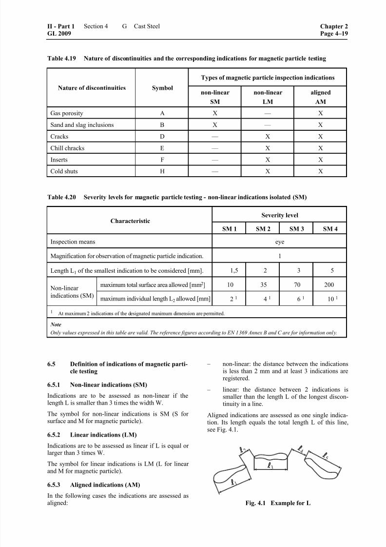
8/10/2019 Casting Material for Shipyards Etc
http://slidepdf.com/reader/full/casting-material-for-shipyards-etc 111/150
Table 4.19 Nature of discontinuities and the corresponding indications for magnetic particle testing
Types of magnetic particle inspection indications
Nature of discontinuities Symbol
non-linearSM
non-linearLM
alignedAM
Gas porosity A X –– X
Sand and slag inclusions B X –– X
Cracks D –– X X
Chill chracks E –– X X
Inserts F –– X X
Cold shuts H –– X X
Table 4.20 Severity levels for magnetic particle testing - non-linear indications isolated (SM)
Severity levelCharacteristic
SM 1 SM 2 SM 3 SM 4
Inspection means eye
Magnification for observation of magnetic particle indication. 1
Length L1 of the smallest indication to be considered [mm]. 1,5 2 3 5
maximum total surface area allowed [mm2
] 10 35 70 200 Non-linearindications (SM)
maximum individual length L2 allowed [mm] 2 1 4 1 6 1 10 1
1 At maximum 2 indications of the designated maximum dimension are permitted.
Note
Only values expressed in this table are valid. The reference figures according to EN 1369 Annex B and C are for information only.
6.5 Definition of indications of magnetic parti-cle testing
6.5.1 Non-linear indications (SM)
Indications are to be assessed as non-linear if thelength L is smaller than 3 times the width W.
The symbol for non-linear indications is SM (S forsurface and M for magnetic particle).
6.5.2 Linear indications (LM)
Indications are to be assessed as linear if L is equal orlarger than 3 times W.
The symbol for linear indications is LM (L for linearand M for magnetic particle).
6.5.3 Aligned indications (AM)
In the following cases the indications are assessed asaligned:
– non-linear: the distance between the indicationsis less than 2 mm and at least 3 indications areregistered.
– linear: the distance between 2 indications issmaller than the length L of the longest discon-tinuity in a line.
Aligned indications are assessed as one single indica-tion. Its length equals the total length L of this line,see Fig. 4.1.
Fig. 4.1 Example for L
II - Part 1GL 2009
Section 4 Cast Steel Chapter 2Page 4–19
G

8/10/2019 Casting Material for Shipyards Etc
http://slidepdf.com/reader/full/casting-material-for-shipyards-etc 112/150
Table 4.21 Severity levels for magnetic particle testing - linear (LM) and aligned (AM) indications
The symbol for aligned indications is AM (A foraligned and M for magnetic particle).
Note:
The total length L equals the distance between the start of the first indication and the end of the lastindication.
Example: + + 1 2 3 4 5 L = + +
6.6 Defects which concerning their size andnumber exceed the requirements for the prescribedseverity levels as well as cracks are not allowed andshall be removed. Repaired zones shall be retested.
7. Penetrant testing (PT)
7.1 Testing is to be performed with an inspectionsystem consisting of penetrant remover, penetrant anddeveloper in accordance with Chapter 1 – Principlesand Test Procedures, Section 3, J.
7.2 The surface of the cast steel component to betested shall correspond to the requirements for thesurface condition specified in 6.1 and 4.
7.3 The indications shall be evaluated concerningtheir type, size and number in accordance with Tables
4.22, 4.23 and 4.24. The reference area for this shall
be a rectangle with 105 mm × 148 mm (size DIN A6)
and shall be placed on the specific most unfavourablearea for each case (area with the highest number of
indications). In addition for the evaluation the refer-
ence figures according to EN 1371-1 part 2, or another
recognized standard, may be consulted.
7.4 Definition of indications of penetranttesting
7.4.1 Linear indication (LP)
Indication where the largest dimension equals at least
3 times the smallest dimension (i.e. L ≥ 3 W).
Chapter 2Page 4–20
Section 4 Cast Steel II - Part 1GL 2009
G

8/10/2019 Casting Material for Shipyards Etc
http://slidepdf.com/reader/full/casting-material-for-shipyards-etc 113/150
Table 4.22 Nature of discontinuities and type of corresponding indications for penetrant testing
Type of corresponding indications for penetrant testing
non-linearNature of discontinuities Symbol
isolated
SP
clustered
CP
linear
LP
aligned
AP
Gas porosity A X X –– X
Sand and slag inclusions B X X –– X
Cracks D –– –– X X
Chill cracks E –– –– X X
Inserts F X –– X X
Cold Shuts H –– –– X X
Table 4.23 Severity levels for penetrant testing - non-linear indications 1, isolated (SP) or clustered (CP)
Severity Levels
Characteristic SP1
CP1
SP2
CP2
SP3
CP3SP4
Inspection means eye
Magnification for observation of penetrant indication 1
Diameter of the smallest indication to be considered [mm] 1,5 2 3 5
Maximum number of non-linear indications allowed 8 8 12 20
Maximum size of discontinuity indication A, B and F [mm]
– isolated indications SP 3 6 9 14
– clustered indications CP 10 16 25 ––
1 Such that L ≤ 3 W where L is the length and W is the width of the indication.
Note
Only values expressed in this table are valid. The reference figures according to EN 1371-1 Annex B and C are for information only.
7.4.2 Non-linear indication
Indication where the largest dimension is smaller than3 times the smallest dimension (i.e. L < 3 W).
– isolated (SP)
– cumulative (CP): area with many indications,the distance between the indications can not bemeasured (seemingly they form only one singleindication)
7.4.3 Aligned indications (AP)
– linear: the distance between 2 indications is smaller
than the length of the largest defect in the line; or – non-linear: the distance between 2 indications is
less than 2 mm and at least 3 indications are reg-istered.
7.5 Defects which concerning their size andnumber exceed the requirements for the prescribedseverity levels as well as discontinuities in the mate-rial (cracks) are not allowed and shall be removed.
Repaired zones shall be retested. For this the sameinspection system as before shall be employed.
8. Ultrasonic testing (UT)
8.1 Ultrasonic testing is preferably performed forcast steel components with larger wall thickness andfor examination of fabrication weldings as well as in
addition to radiographic testing for determining the position in thickness and the dimension of defects, andshall be performed in accordance with Chapter 1 –Principles and Test Procedures, Section 3, K.
II - Part 1GL 2009
Section 4 Cast Steel Chapter 2Page 4–21
G
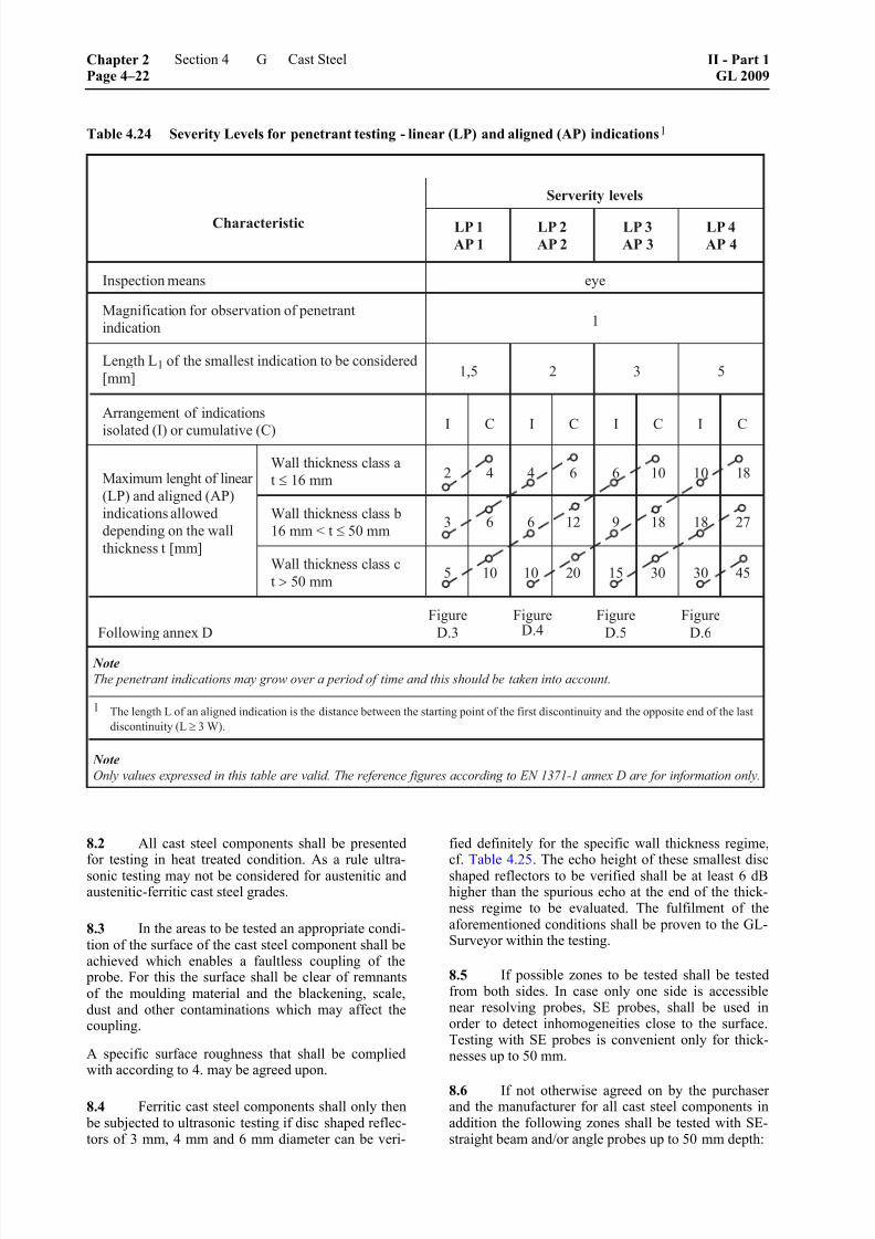
8/10/2019 Casting Material for Shipyards Etc
http://slidepdf.com/reader/full/casting-material-for-shipyards-etc 114/150
Table 4.24 Severity Levels for penetrant testing - linear (LP) and aligned (AP) indications 1
8.2 All cast steel components shall be presentedfor testing in heat treated condition. As a rule ultra-sonic testing may not be considered for austenitic andaustenitic-ferritic cast steel grades.
8.3 In the areas to be tested an appropriate condi-tion of the surface of the cast steel component shall beachieved which enables a faultless coupling of the
probe. For this the surface shall be clear of remnantsof the moulding material and the blackening, scale,dust and other contaminations which may affect thecoupling.
A specific surface roughness that shall be compliedwith according to 4. may be agreed upon.
8.4 Ferritic cast steel components shall only then be subjected to ultrasonic testing if disc shaped reflec-tors of 3 mm, 4 mm and 6 mm diameter can be veri-
fied definitely for the specific wall thickness regime,cf. Table 4.25. The echo height of these smallest discshaped reflectors to be verified shall be at least 6 dBhigher than the spurious echo at the end of the thick-ness regime to be evaluated. The fulfilment of theaforementioned conditions shall be proven to the GL-Surveyor within the testing.
8.5 If possible zones to be tested shall be testedfrom both sides. In case only one side is accessiblenear resolving probes, SE probes, shall be used inorder to detect inhomogeneities close to the surface.Testing with SE probes is convenient only for thick-nesses up to 50 mm.
8.6 If not otherwise agreed on by the purchaserand the manufacturer for all cast steel components inaddition the following zones shall be tested with SE-straight beam and/or angle probes up to 50 mm depth:
Chapter 2Page 4–22
Section 4 Cast Steel II - Part 1GL 2009
G

8/10/2019 Casting Material for Shipyards Etc
http://slidepdf.com/reader/full/casting-material-for-shipyards-etc 115/150
Table 4.25 Ultrasonic testability requirements according to EN 12680-1
Wall thickness
mm
Smallest flat-bottom hole diameter detectable
mm
≤ 300 3
> 300 to ≤ 400 4
> 400 to ≤ 600 6
Table 4.26 Registration levels for ultrasonic testing of ferritic steel castings in accordance with EN 12680-1
Wall thickness
[mm]
Inspected
area
Reflectors without
measurable dimension
diameter of theequivalent
flat-bottomed hole 1
min.
[mm]
Reflectors with
measurable dimension
diameter of theequivalent
flat-bottomed hole 1
min.
[mm]
Attenuation of
back wall echo
min.
[mm]
≤ 300 – 4 3
> 300 to ≤ 400 – 6 4
> 400 to ≤ 600 – 6 6
12
–Severity level 1
areas3 3 6
– special rim zone 3 3 –
1 Formula for converting the flat-bottomed hole diameter into the side-drilled hole diameter, see EN 12680-1.
– Grooves, transitions in wall thickness, zoneswith outer cooling webs
– Fabrication weldings, welding edges and specialrim zones
– Fabrication weldings with depths exceeding50 mm shall be tested in addition with other ap- propriate angle probes.
8.7 All echo indications and attenuations of the back wall echo shall be registered which are equal tothe registration levels indicated in Table 4.26 or ex-ceed them.
8.8 Indications exceeding the acceptance limitscontained in Table 4.27 or Fig. 4.3 are not allowed andwill result in rejection of the cast steel component bythe Surveyor. Nevertheless acceptance of the cast steelcomponent is possible on condition that after further
evaluation of the indications performed by the ordererand GL proof has been furnished that in case no repairwill be performed the employability of the cast steelcomponent will not be effected considerably, or repair
will be performed. In the later case the testing shall berepeated.
8.9 For determining the acceptance criteria ac-cording to Table 4.27 the cast wall is to be divided in
rim and core zones according to Fig. 4.2.
(The classification of the wall refers to the dimen-
sions of the cast steel component ready for assem- bling.)
Fig. 4.2 Deviation of wall section into zones
II - Part 1GL 2009
Section 4 Cast Steel Chapter 2Page 4–23
G

8/10/2019 Casting Material for Shipyards Etc
http://slidepdf.com/reader/full/casting-material-for-shipyards-etc 116/150
Table 4.27 Acceptance limits for ultrasonic testing for volumetric discontinuities following EN 12680-1
Chapter 2Page 4–24
Section 4 Cast Steel II - Part 1GL 2009
G

8/10/2019 Casting Material for Shipyards Etc
http://slidepdf.com/reader/full/casting-material-for-shipyards-etc 117/150
Fig. 4.3 Acceptance criteria for ultrasonic testing for individual planar indications mainly orientated inthrough-wall direction, detected with angle probes following EN 12680-1
II - Part 1GL 2009
Section 4 Cast Steel Chapter 2Page 4–25
G
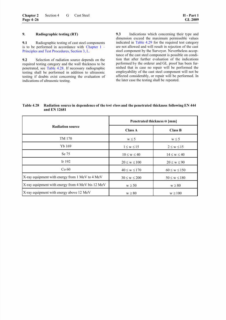
8/10/2019 Casting Material for Shipyards Etc
http://slidepdf.com/reader/full/casting-material-for-shipyards-etc 118/150
9. Radiographic testing (RT)
9.1 Radiographic testing of cast steel componentsis to be performed in accordance with Chapter 1 –Principles and Test Procedures, Section 3, L.
9.2 Selection of radiation source depends on therequired testing category and the wall thickness to be
penetrated, see Table 4.28. If necessary radiographictesting shall be performed in addition to ultrasonictesting if doubts exist concerning the evaluation ofindications of ultrasonic testing.
9.3 Indications which concerning their type anddimension exceed the maximum permissible valuesindicated in Table 4.29 for the required test categoryare not allowed and will result in rejection of the caststeel component by the Surveyor. Nevertheless accep-
tance of the cast steel component is possible on condi-tion that after further evaluation of the indications performed by the orderer and GL proof has been fur-nished that in case no repair will be performed theemployability of the cast steel component will not beaffected considerably, or repair will be performed. Inthe later case the testing shall be repeated.
Table 4.28 Radiation source in dependence of the test class and the penetrated thickness following EN 444and EN 12681
Penetrated thickness ω [mm]
Radiation sourceClass A Class B
TM 170 w 5≤ w 5≤
Yb 169 1 w 15≤ ≤ 2 w 15≤ ≤
Se 75 10 w 40≤ ≤ 14 w 40≤ ≤
Ir 192 20 w 100≤ ≤ 20 w 90≤ ≤
Co 60 40 w 170≤ ≤ 60 w 150≤ ≤
X-ray equipment with energy from 1 MeV to 4 MeV 30 w 200≤ ≤ 50 w 180≤ ≤
X-ray equipment with energy from 4 MeV bis 12 MeV w 50≥ w 80≥
X-ray equipment with energy above 12 MeV w 80≥ w 100≥
Chapter 2Page 4–26
Section 4 Cast Steel II - Part 1GL 2009
G
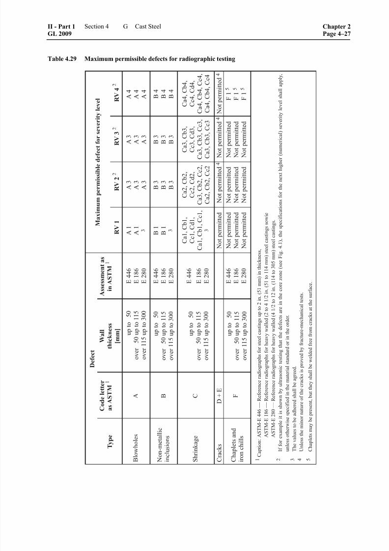
8/10/2019 Casting Material for Shipyards Etc
http://slidepdf.com/reader/full/casting-material-for-shipyards-etc 119/150
Table 4.29 Maximum permissible defects for radiographic testing
II - Part 1GL 2009
Section 4 Cast Steel Chapter 2Page 4–27
G
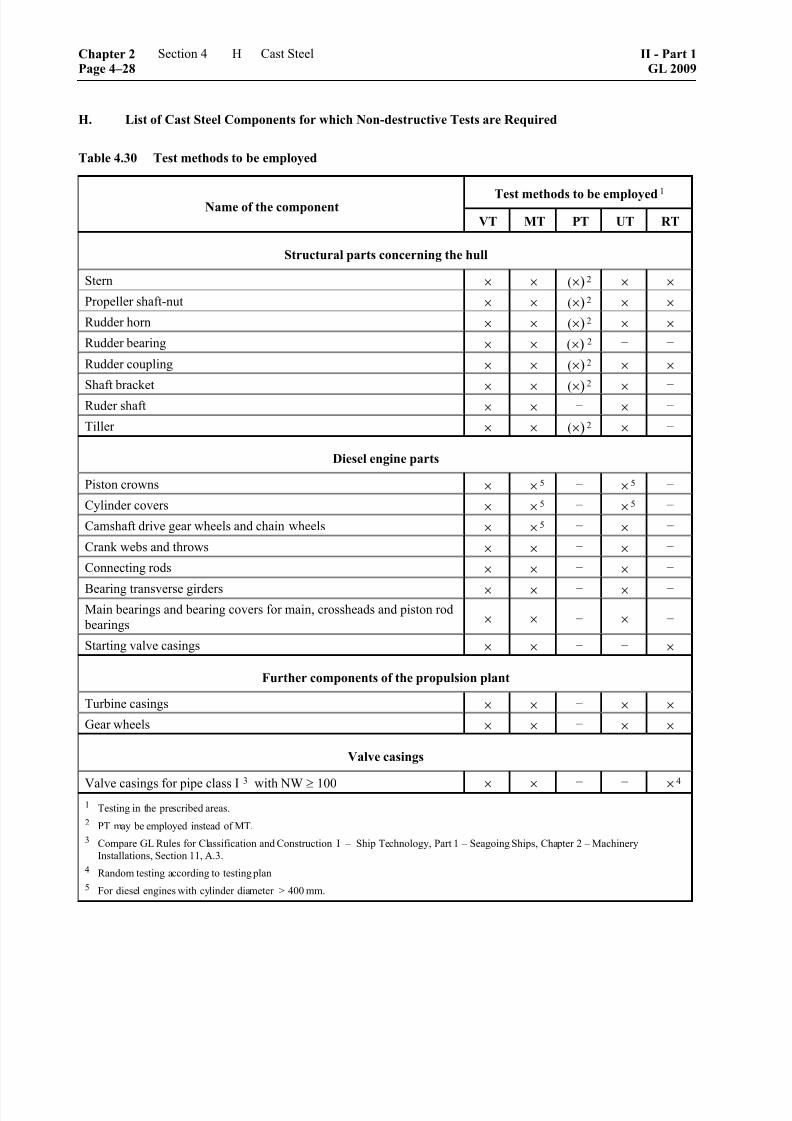
8/10/2019 Casting Material for Shipyards Etc
http://slidepdf.com/reader/full/casting-material-for-shipyards-etc 120/150
H. List of Cast Steel Components for which Non-destructive Tests are Required
Table 4.30 Test methods to be employed
Test methods to be employed 1
Name of the componentVT MT PT UT RT
Structural parts concerning the hull
Stern × × (×) 2 × ×
Propeller shaft-nut × × (×) 2 × ×
Rudder horn × × (×) 2 × ×
Rudder bearing × × (×) 2 – –
Rudder coupling × × (×) 2 × ×
Shaft bracket× × (×)
2
× –
Ruder shaft × × – × –
Tiller × × (×) 2 × –
Diesel engine parts
Piston crowns × × 5 – × 5 –
Cylinder covers × × 5 – × 5 –
Camshaft drive gear wheels and chain wheels × × 5 – × –
Crank webs and throws × × – × –
Connecting rods × × – × –
Bearing transverse girders × × – × – Main bearings and bearing covers for main, crossheads and piston rod
bearings × × – × –
Starting valve casings × × – – ×
Further components of the propulsion plant
Turbine casings × × – × ×
Gear wheels × × – × ×
Valve casings
Valve casings for pipe class I3
with NW ≥ 100 × × – – × 4
1 Testing in the prescribed areas.
2 PT may be employed instead of MT.
3 Compare GL Rules for Classification and Construction I – Ship Technology, Part 1 – Seagoing Ships, Chapter 2 – Machinery
Installations, Section 11, A.3.
4 Random testing according to testing plan
5 For diesel engines with cylinder diameter > 400 mm.
Chapter 2Page 4–28
Section 4 Cast Steel II - Part 1GL 2009
H

8/10/2019 Casting Material for Shipyards Etc
http://slidepdf.com/reader/full/casting-material-for-shipyards-etc 121/150
I. Testing Instructions for Hull Structural Parts
In the figures 4.4 to 4.11 the specifications for the non-destructive testings are prescribed.
Fig. 4.4 Testing instruction for stern
II - Part 1GL 2009
Section 4 Cast Steel Chapter 2Page 4–29
I

8/10/2019 Casting Material for Shipyards Etc
http://slidepdf.com/reader/full/casting-material-for-shipyards-etc 122/150
Fig. 4.5 Testing instruction for rudder stock
Chapter 2Page 4–30
Section 4 Cast Steel II - Part 1GL 2009
I

8/10/2019 Casting Material for Shipyards Etc
http://slidepdf.com/reader/full/casting-material-for-shipyards-etc 123/150
Fig. 4.6 Testing instruction for stern nut
II - Part 1GL 2009
Section 4 Cast Steel Chapter 2Page 4–31
I

8/10/2019 Casting Material for Shipyards Etc
http://slidepdf.com/reader/full/casting-material-for-shipyards-etc 124/150
Fig. 4.7 Testing instruction for rudder horn
Chapter 2Page 4–32
Section 4 Cast Steel II - Part 1GL 2009
I

8/10/2019 Casting Material for Shipyards Etc
http://slidepdf.com/reader/full/casting-material-for-shipyards-etc 125/150

8/10/2019 Casting Material for Shipyards Etc
http://slidepdf.com/reader/full/casting-material-for-shipyards-etc 126/150
Fig. 4.9 Testing instruction for lower rudder coupling
Chapter 2Page 4–34
Section 4 Cast Steel II - Part 1GL 2009
I

8/10/2019 Casting Material for Shipyards Etc
http://slidepdf.com/reader/full/casting-material-for-shipyards-etc 127/150
Fig. 4.10 Testing instruction for stern frame
II - Part 1GL 2009
Section 4 Cast Steel Chapter 2Page 4–35
I
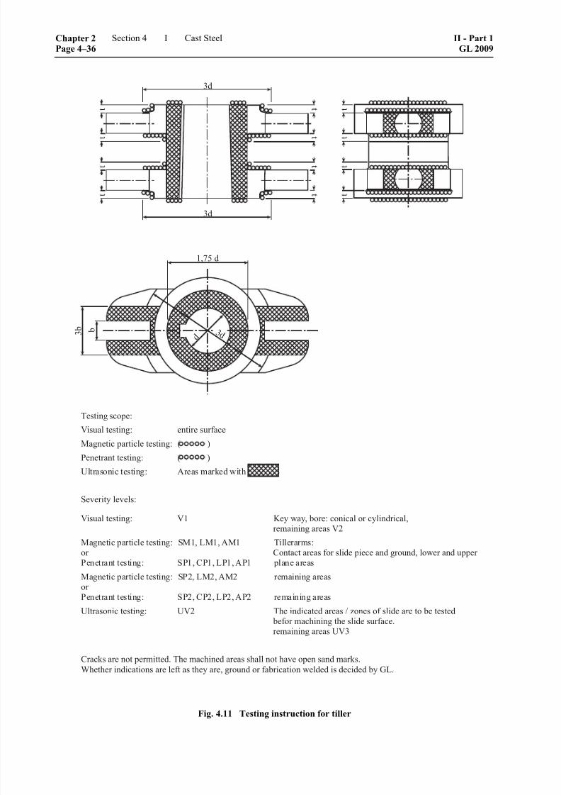
8/10/2019 Casting Material for Shipyards Etc
http://slidepdf.com/reader/full/casting-material-for-shipyards-etc 128/150
Fig. 4.11 Testing instruction for tiller
Chapter 2Page 4–36
Section 4 Cast Steel II - Part 1GL 2009
I

8/10/2019 Casting Material for Shipyards Etc
http://slidepdf.com/reader/full/casting-material-for-shipyards-etc 129/150
J. Testing Instruction for Diesel Engine Parts
In the figures 4.12 and 4.13 the specifications for the non-destructive testings are prescribed.
Fig. 4.12 Testing instruction for connecting rods
II - Part 1GL 2009
Section 4 Cast Steel Chapter 2Page 4–37
J

8/10/2019 Casting Material for Shipyards Etc
http://slidepdf.com/reader/full/casting-material-for-shipyards-etc 130/150
Fig. 4.13 Testing instruction for main bearing support
Chapter 2Page 4–38
Section 4 Cast Steel II - Part 1GL 2009
J

8/10/2019 Casting Material for Shipyards Etc
http://slidepdf.com/reader/full/casting-material-for-shipyards-etc 131/150
Section 5
Cast Iron
A. General Rules
1. Scope
General Rules to be applied in the manufacture andtesting of nodular and grey cast iron are contained in A.
2. Selection of grades of cast iron
2.1 All castings shall be suitable for their in-
tended purpose and satisfy the minimum requirementsspecified in the following individual Rules. Subject tothese conditions, grades conforming to the relevantstandards or to material specifications approved by GLmay be used.
2.2 The grades of cast iron shall be identified bythe standardized designations or the designations inthe specifications.
3. Requirements to be met by foundries
3.1 Foundries wishing to supply castings in ac-
cordance with these Rules shall be approved by GL.This is conditional upon their fulfilling the manufac-turing and quality control requirements stated inChapter 1 – Principles and Test Procedures, Section 1,C. and furnishing proof of this to GL prior to thecommencement of supplies.
3.2 Irrespective of the requirements stated in 2.1,the manufacturer shall himself prove by qualificationtests carried out on the products that these can bemanufactured in accordance with the conditions im-
posed. The scope of these tests will be determined byGL on a case to case basis.
4. General characteristics of castings
4.1 All castings shall have a clean surface com- patible with the conditions of manufacture. Minorcasting defects such as sand and slag marks, smallcold shuts and scabs may be trimmed off within thenegative tolerance on the wall thickness. Castingsshall be free from defects liable to impair machiningoperations and their subsequent use to a more thaninsignificant extent.
In this respect orderer and manufacturer have to agreeon specific grade levels according to EN 1369,
EN 1371-1, EN 12680-3 and EN 12681.
4.2 Feeders and other excess material shall beremoved by suitable methods. Where the method of
removal causes a change of structure, e.g. in the caseof flame cutting, the cut faces shall afterwards bemachined.
4.3 Fabrication and repair welds, be it dissimilarwelding by means of fillers with high nickel content orsimilar welding, i.e. using similar fillers, have to be inany case subject to a welding procedure test at the
presence of the Surveyor. GL decides about a cast- orcomponent-specific application of the above men-
tioned procedure.
4.4 With the consent of the Surveyor, local po-rous areas on castings not subjected to internal pres-sure may be corrected applying appropriate proce-dures, such as inserting filler pieces of similar mate-rial. It is a condition that the serviceability of the cast-ings shall not be impaired by this.
5. Dimensions; dimensional and geometrical
tolerances
The dimensions and the dimensional and geometrical
tolerances are governed by the values specified in thedrawings relating to the order or in the relevant stan-dards, as applicable. Appropriate details shall be givenin the order documents and shall be made known tothe Surveyor.
6. Resistance to leakage
All castings which are subjected to internal pressure by the operating medium or for which special proof ofimpermeability is required shall be tightness tested atthe specified test pressures.
7. General requirements applicable to castmaterials
7.1 Chemical composition
Unless otherwise agreed or specified in the standards,the chemical composition shall be selected by themanufacturer. The manufacturer shall determine thecomposition in such a way that the required character-istics are achieved.
7.2 Mechanical properties
The values shown in the Tables in B. and C. or in the
standards, where applicable, shall be met under test.The impact energy specified for special quality nodu-lar cast iron grades shall be met by the average valuemeasured on 3 specimens.
II - Part 1GL 2009
Section 5 Cast Iron Chapter 2Page 5–1
A

8/10/2019 Casting Material for Shipyards Etc
http://slidepdf.com/reader/full/casting-material-for-shipyards-etc 132/150
8. Tests
The following tests are to be carried out:
8.1 Test of chemical composition
Where required, the manufacturer shall determine thecomposition of each treatment batch (ladle) and givethe Surveyor a certificate confirming this composition.
8.2 Testing of mechanical properties and selec-tion of specimens
8.2.1 The mechanical properties shall be ascer-tained by tensile test. In the case of special qualitynodular cast iron for which an impact energy is speci-fied, a notched bar impact test shall also be performed.
8.2.2 For each casting or unit test quantity, as ap-
plicable, a sufficient quantity of sample material shall be provided to enable the necessary tests and possibleretests to be performed.
8.2.3 For proof of the mechanical properties sepa-rately cast samples, integrally cast samples or samplestaken from the casting unit may be used.
8.2.4 Type, quantity and location of the respectivesamples are to be agreed between orderer and manu-facturer until acceptance of the order, unless otherwisespecified.
8.2.5 For casting units with cast weights of maxi-
mum 2000 kg and a determining wall thickness of upto 200 mm integrally cast samples are to be used. Ifthe weight of the casting unit exceeds 2000 kg and thedetermining wall thickness is larger than 200 mmintegrally cast samples or samples taken from thecasting unit are to be used. The latter is to be agreed
between the manufacturer and the orderer as well asGL under consideration of 8.2.4.
8.2.6 Where separately cast samples are used, theseshall be cast in moulds made of the same mould mate-rial as that used for the casting itself. The samples maynot be removed from the moulds until their tempera-
ture has dropped to below 500 °C. In the case of chillcasting, centrifugal casting and continuous casting,special agreements shall be reached with GL regardingthe selection of samples.
8.2.7 All samples are to be marked in such a waythat they can be clearly related to the castings whichthey are intended to represent.
8.2.8 Where castings are supplied in a heat-treatedcondition, the samples shall be heat treated togetherwith the castings concerned.
8.2.9 Where castings are manufactured in series,
the manufacturer may, with the agreement of GL, useother, equivalent methods of testing. In this case, themanufacturer shall have proved the characteristics ofthe products by a preliminary type test and shall en-
sure by continuous quality control that the characteris-tics remain constant.
9. Test of surface finish and dimensions
The manufacturer shall inspect each casting with re-gard to its surface finish and compliance with thedimensional and geometrical tolerances and shall then
present the castings to the Surveyor for final inspec-tion. For this purpose, the surface of the castings shall
be free from moulding material and shall be properly prepared for inspection.
10. Non-destructive tests
Generally, a non-destructive test shall be performedonly where this is specified in the order according to4.1. Apart from this, the Surveyor may call for suit-able non-destructive tests if there are justified doubts
that the castings are free from defects.
11. Hydraulic pressure test
Where specified, castings shall be submitted to a hy-draulic pressure test. The test is to be performed in the
presence of the Surveyor, wherever possible on therough-machined castings. Where no other test pressureis specified, the test pressure shall be equal to 1,5times the operating pressure.
12. Retests in the event of failure
If specimens fail to meet the required values in thetensile or notched bar impact test, or if, in the notched bar impact tests, one value is below the level permit-ted by the specification, then, before the unit testquantity or the casting is rejected, the procedures forretests prescribed in Chapter 1 – Principles and TestProcedures, Section 2, H. may be applied. The addi-tional test specimens shall be taken either from thesame test sample as the original specimen or fromother samples which are representative of the castingor of the unit test quantity.
13. Identification and marking
13.1 The manufacturer shall institute a monitoringsystem enabling all castings to be traced back to theoriginal heat, and this shall be demonstrated to theSurveyor on request.
13.2 Prior to final inspection, all castings shall be provided by the manufacturer in at least one placewith the following marks:
13.3 Grade of cast iron, material symbol and/ormaterial number of the cast material:
– heat number or mark enabling the manufactur-
ing process of the casting to be traced back
– manufacturer's name or mark
– test pressure, where applicable
Chapter 2Page 5–2
Section 5 Cast Iron II - Part 1GL 2009
A

8/10/2019 Casting Material for Shipyards Etc
http://slidepdf.com/reader/full/casting-material-for-shipyards-etc 133/150
13.4 In the case of series-manufactured castings,agreement may be reached with the Surveyor to applymarks other than those specified above.
14. Certificates
For each consignment, the manufacturer shall supplyto the Surveyor a certificate containing at least thefollowing details:
– orderer and order number
– newbuilding or project number, where known
– item number and quantity
– type of casting units and grade of cast iron
– application and drawing number, if necessary
– weight of products
– manufacturing process
– heat number or identifying mark
– chemical composition of the heat
– condition of supply
– details of heat treatment, if necessary
– marking
– test pressures, if necessary
– results of mechanical tests
B. Nodular Cast Iron
1. Scope
These Rules are applicable to nodular cast iron for themanufacture of machinery and pipeline components,e.g. fittings, flanges, housings, hubs, bed-plates andsimilar parts designed for use and testing at normalambient temperatures.
The requirements for the use of castings at higheroperating temperatures or at low temperatures gener-ally below 0 °C are subject to the special agreement ofGL.
2. Suitable grades of cast iron
The following grades of cast iron may be used:
2.1 Nodular cast iron conforming to DIN EN 1563with the characteristics stated in the standard.
2.2 Nodular cast iron grades conforming to otherstandards, provided that they are equivalent to thegrades specified in 2.1 and satisfy the requirementsstated in 4.2 to 4.4.
3. Condition of supply and heat treatment
3.1 Apart from the exceptions provided for in3.2, the castings may be supplied in as cast or heat-treated condition. The method of treatment shall be
specified at the time of the approval test.
3.2 Cast iron of grades EN-GJS-350-22-LT/-22-U-LT to EN-GJS-400-18-LT/-18U-LT or the specialqualities according to Table 5.1 with nominalstrengths of 350 and 400 N/mm2 shall undergo ferri-tizing treatment.
3.3 Where castings are subject to special re-quirements in respect of their dimensional or geomet-rical stability, any heat treatments needed shall becarried out before the castings are machined.
Heat treatments to eliminate casting stresses or for
straightening may only be carried out at temperaturesup to 550 °C because of the danger that the character-istics might be changed.
4. Requirements applicable to the material
4.1 Nodular cast iron conforming toDIN EN 1563
The requirements specified in the standard and givenin Table 5.2 for separately cast samples and in Table5.3 for integrally cast samples are applicable.
In case of requirements regarding impact energy, theminimum values specified in Tables 5.4 and 5.5 are to
be proven.
In addition the requirements in 4.3 and 4.4 apply re-garding graphite- or metallic matrix structure respec-tively.
4.2 Other grades of cast iron
4.2.1 The castings shall achieve the mechanical properties specified in Table 5.1 in testing, dependingon their minimum tensile strength. The Brinell hard-ness data are only guide values.
4.2.2 Special quality castings shall meet the re-quired energy impact values specified in Table 5.1.
4.3 Graphite structure
The manufacturing process shall ensure that 90 % ofthe graphite is precipitated in nodular form accordingto Form VI of EN ISO 945. The remaining graphiteshall have a structure at least of form V according tothe above mentioned standard.
4.4 Structure of metallic matrix
The metallic matrix shall have the structure indicated
in Table 5.1. The proportion of pearlite in the ferriticgrades may not exceed 10 %. The graphite- and metal-lic matrix structures are to be demonstrated by micro-graphs.
II - Part 1GL 2009
Section 5 Cast Iron Chapter 2Page 5–3
B

8/10/2019 Casting Material for Shipyards Etc
http://slidepdf.com/reader/full/casting-material-for-shipyards-etc 134/150
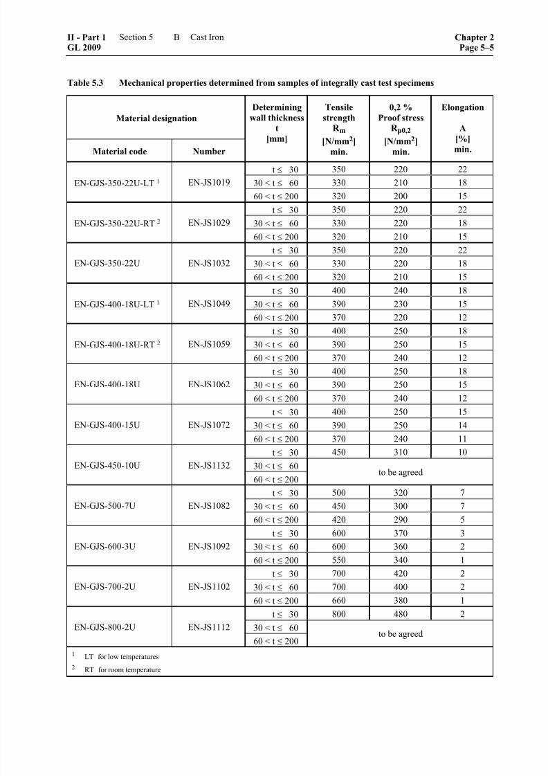
8/10/2019 Casting Material for Shipyards Etc
http://slidepdf.com/reader/full/casting-material-for-shipyards-etc 135/150
Table 5.3 Mechanical properties determined from samples of integrally cast test specimens
Material designation
Material code Number
Determining
wall thickness
t
[mm]
Tensile
strength
R m
[N/mm2]
min.
0,2 %
Proof stress
R p0,2
[N/mm2]
min.
Elongation
A
[%]min.
t ≤ 30 350 220 22
30 < t ≤ 60 330 210 18EN-GJS-350-22U-LT 1 EN-JS1019
60 < t ≤ 200 320 200 15
t ≤ 30 350 220 22
30 < t ≤ 60 330 220 18EN-GJS-350-22U-RT 2 EN-JS1029
60 < t ≤ 200 320 210 15
t ≤ 30 350 220 22
30 < t ≤ 60 330 220 18EN-GJS-350-22U EN-JS1032
60 < t ≤ 200 320 210 15
t ≤ 30 400 240 18
30 < t ≤ 60 390 230 15EN-GJS-400-18U-LT 1 EN-JS1049
60 < t ≤ 200 370 220 12
t ≤ 30 400 250 18
30 < t ≤ 60 390 250 15EN-GJS-400-18U-RT 2 EN-JS1059
60 < t ≤ 200 370 240 12
t ≤ 30 400 250 18
30 < t ≤ 60 390 250 15EN-GJS-400-18U EN-JS1062
60 < t ≤ 200 370 240 12
t ≤ 30 400 250 15
30 < t ≤ 60 390 250 14EN-GJS-400-15U EN-JS1072
60 < t ≤ 200 370 240 11
t ≤ 30 450 310 10
30 < t ≤ 60EN-GJS-450-10U EN-JS1132
60 < t ≤ 200to be agreed
t ≤ 30 500 320 7
30 < t ≤ 60 450 300 7EN-GJS-500-7U EN-JS1082
60 < t ≤ 200 420 290 5
t ≤ 30 600 370 3
30 < t ≤ 60 600 360 2EN-GJS-600-3U EN-JS1092
60 < t ≤ 200 550 340 1
t ≤ 30 700 420 2
30 < t ≤ 60 700 400 2EN-GJS-700-2U EN-JS1102
60 < t ≤ 200 660 380 1
t ≤ 30 800 480 2
30 < t ≤ 60EN-GJS-800-2U EN-JS1112
60 < t ≤ 200to be agreed
1 LT for low temperatures
2 RT for room temperature
II - Part 1GL 2009
Section 5 Cast Iron Chapter 2Page 5–5
B
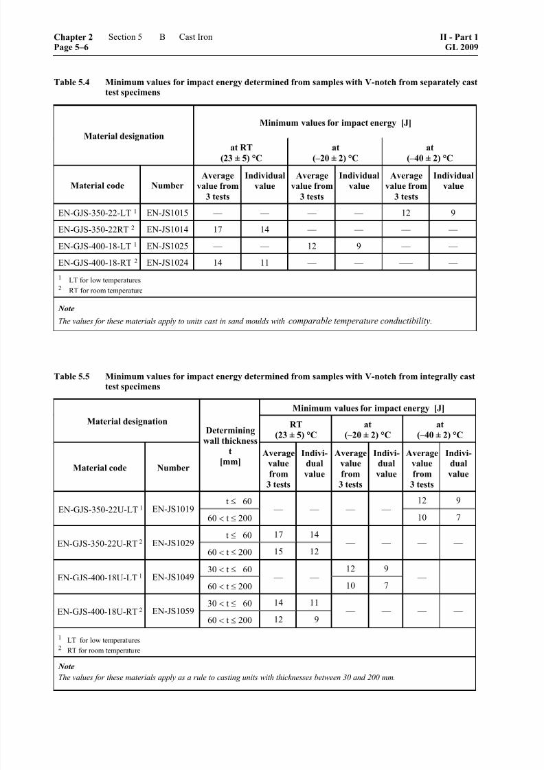
8/10/2019 Casting Material for Shipyards Etc
http://slidepdf.com/reader/full/casting-material-for-shipyards-etc 136/150
Table 5.4 Minimum values for impact energy determined from samples with V-notch from separately casttest specimens
Minimum values for impact energy [J]
Material designationat RT
(23 ± 5) °C
at
(–20 ± 2) °C
at
(–40 ± 2) °C
Material code NumberAverage
value from
3 tests
Individual
value
Average
value from
3 tests
Individual
value
Average
value from
3 tests
Individual
value
EN-GJS-350-22-LT 1 EN-JS1015 –– –– –– –– 12 9
EN-GJS-350-22RT 2 EN-JS1014 17 14 –– –– –– ––
EN-GJS-400-18-LT 1 EN-JS1025 –– –– 12 9 –– ––
EN-GJS-400-18-RT 2 EN-JS1024 14 11 –– –– ––– ––
1 LT for low temperatures2 RT for room temperature
Note
The values for these materials apply to units cast in sand moulds with comparable temperature conductibility.
Table 5.5 Minimum values for impact energy determined from samples with V-notch from integrally casttest specimens
Minimum values for impact energy [J]
Material designation RT
(23 ± 5) °C
at
(–20 ± 2) °C
at
(–40 ± 2) °C
Material code Number
Determining
wall thickness
t
[mm]Average
value
from
3 tests
Indivi-
dual
value
Average
value
from
3 tests
Indivi-
dual
value
Average
value
from
3 tests
Indivi-
dual
value
t ≤ 60 12 9EN-GJS-350-22U-LT 1 EN-JS1019
60 < t ≤ 200 –– –– –– ––
10 7
t≤
6017 14
EN-GJS-350-22U-RT 2 EN-JS102960 < t ≤ 200 15 12
–– –– –– ––
30 < t ≤ 60 12 9EN-GJS-400-18U-LT 1 EN-JS1049
60 < t ≤ 200 –– ––
10 7 –– ––
30 < t ≤ 60 14 11EN-GJS-400-18U-RT 2 EN-JS1059
60 < t ≤ 200 12 9 –– –– –– ––
1 LT for low temperatures2 RT for room temperature
Note
The values for these materials apply as a rule to casting units with thicknesses between 30 and 200 mm.
Chapter 2Page 5–6
Section 5 Cast Iron II - Part 1GL 2009
B

8/10/2019 Casting Material for Shipyards Etc
http://slidepdf.com/reader/full/casting-material-for-shipyards-etc 137/150
5. Testing
The following tests shall be performed:
5.1 Test of chemical composition
The manufacturer shall determine and make known tothe Surveyor the chemical composition of each heattreatment batch. The analysis report shall cover atleast the following elements:
C, Si, Mn, P, S and Mg together with Ni and Cu,where these are added to achieve the required charac-teristics.
5.2 Testing of mechanical properties and selec-
tion of specimens
5.2.1 The mechanical properties such as tensilestrength, 0,2 % proof stress and elongation shall be
determined by tensile test. In the case of ferriticgrades, the yield point revealed by the curve plotted
by the testing machine may be stated instead of the0,2 % proof stress.
5.2.2 For the tensile test, one test specimen eachshall be taken from a separately cast U- or a Y-shapedsample piece according to Fig. 5.1 and 5.2 respec-tively or from an integrally cast sample piece accord-ing to Fig. 5.3. The shape of the sample piece shallnormally correspond to the standard U or Y2 type witha thickness of 25 mm. In special cases, samples havingdifferent dimensions may be agreed. The provision of
samples is governed by the following requirements: – For heavy casting units with gross weights of
minimum 1000 kg one sample plus one sample per treatment batch shall be provided.
– For casting units with gross weights of less than1000 kg one sample per treatment batch shall be
provided. In case of testing by batch one sample per 1000 kg gross weight of the test batch shall be provided and one additional sample for eachfurther 2000 kg gross weight of the test batch.Precondition is that all casting units are from aseries of the same type and have been cast fromthe same treatment batch and heat treated, whereapplicable.
– Where heat treatments are carried out, integrallycast samples may be removed from the castingonly after heat treatment. Separately cast sam-
ples shall be heat treated together with the cast-ing.
5.3 Notched bar impact test
Where an impact energy is specified for a grade ofcast iron, this shall be verified by the notched barimpact test performed on Charpy V-notch specimensat the prescribed test temperature. The requirements
regarding impact energy are specified in Table 5.1, 5.4 and 5.5 for the respective grades of cast iron. To carryout the test, one set of specimens shall be taken fromeach of the samples called for in 5.2.2.
Dimensions Location of specimen
a = 25 mm Z = tensile test specimen b = 90 mm K = impact test specimenc = 40 mmh = 100 mm
Lt ≥ 200 mm
Fig. 5.1 U-type sample piece
Location of specimen
Z = tensile test specimenK = impact test specimen
Sizes in [mm] for samples of
typeDimen-
sionY 1 Y 2 Y 3 Y 4
a b
c
h
1240
25
135
2555
40
140
50100
50
150
75125
65
175
Lt ≥ 200
Fig. 5.2 Y-type sample piece
5.4 Test of surface finish and dimensions
The manufacturer shall inspect each casting with re-gard to its surface finish and compliance with thedimensional and geometrical tolerances and shall then
present the casting to the Surveyor for final inspection.
II - Part 1GL 2009
Section 5 Cast Iron Chapter 2Page 5–7
B

8/10/2019 Casting Material for Shipyards Etc
http://slidepdf.com/reader/full/casting-material-for-shipyards-etc 138/150
Location of specimen
Z = tensile test specimenK = impact test specimen
A) Casting unit (or cast system) Dimensions in mm
Type
Determining
wall thickness
of casting unit
t
a b c h Lt
I 30 < t ≤ 60 40 30 20 40 to 60 ≥ 200
II 60 < t ≤ 200 70 52,5 35 70 to 105 ≥ 200
If smaller dimensions are agreed, the following correlations apply:a
b 0, 75 a and c2
= ⋅ =
Fig. 5.3 Integrally cast test specimens
C. Grey Cast Iron
1. Scope
These Rules are applicable to grey cast iron for themanufacture of machinery and pipeline components,e.g. fittings, flanges, housings, hubs, wheel bodies,
bed-plates, cylinders, and similar parts.
2. Suitable grades of cast iron
The following grades of cast iron may be used:
2.1 Grey cast iron conforming to DIN EN 1561,with the exception of grades EN-GJL-100 and EN-GJL-150.
2.2 Grades of cast iron conforming to other stan-dards, provided that they are equivalent to the gradesspecified in 2.1 and meet the requirements of 4.
3. Condition of supply and heat treatment
Castings may be supplied in the as cast or heat-treated
condition at the manufacturer's option unless a heattreatment is specified because of special requirementsin respect of machinability or geometrical and dimen-sional stability.
4. Requirements applicable to the material
4.1 Mechanical characteristics
Castings shall normally be supplied with one of thefollowing minimum tensile strengths R m:
200 N/mm2
250 N/mm2
300 N/mm2
350 N/mm2
Castings with minimum tensile strength values of
< 200 N/mm2 are not allowed. The requirements areapplicable to specimens with a diameter of 20 mm inaccordance with 5.2.4. The requirements regardingminimum tensile strength for separately and integrallycast specimens are specified in Table 5.6. The re-quirements for specimens taken from the casting (e.g.core specimens) shall be specially agreed betweenmanufacturer and orderer as well as GL.
4.2 Graphite and matrix structure
The method of manufacture shall ensure that thegraphite is present in uniformly distributed flakes and
Chapter 2Page 5–8
Section 5 Cast Iron II - Part 1GL 2009
C
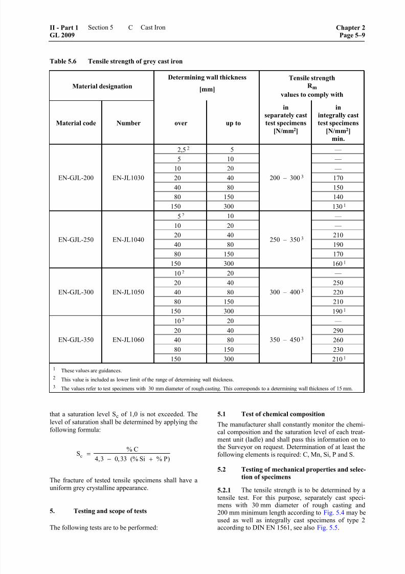
8/10/2019 Casting Material for Shipyards Etc
http://slidepdf.com/reader/full/casting-material-for-shipyards-etc 139/150
Table 5.6 Tensile strength of grey cast iron
Material designation
Determining wall thickness
[mm]
Tensile strength
R m
values to comply with
Material code Number over up to
in
separately cast
test specimens
[N/mm2]
in
integrally cast
test specimens
[N/mm2]
min.
2,5 2 5 ––
5 10 ––
10 20 ––
20 40 170
40 80 150
80 150 140
EN-GJL-200 EN-JL1030
150 300
200 – 300 3
130 1
5 2 10 ––
10 20 ––
20 40 210
40 80 190
80 150 170
EN-GJL-250 EN-JL1040
150 300
250 – 350 3
160 1
10 2 20 ––
20 40 250
40 80 220
80 150 210
EN-GJL-300 EN-JL1050
150 300
300 – 400 3
190 1
10 2 20 ––
20 40 290
40 80 260
80 150 230
EN-GJL-350 EN-JL1060
150 300
350 – 450 3
210 1
1 These values are guidances.
2 This value is included as lower limit of the range of determining wall thickness.
3 The values refer to test specimens with 30 mm diameter of rough casting. This corresponds to a determining wall thickness of 15 mm.
that a saturation level Sc of 1,0 is not exceeded. The
level of saturation shall be determined by applying the
following formula:
c
% CS
4,3 0,33 (% Si % P)=
− +
The fracture of tested tensile specimens shall have auniform grey crystalline appearance.
5. Testing and scope of tests
The following tests are to be performed:
5.1 Test of chemical composition
The manufacturer shall constantly monitor the chemi-cal composition and the saturation level of each treat-ment unit (ladle) and shall pass this information on tothe Surveyor on request. Determination of at least thefollowing elements is required: C, Mn, Si, P and S.
5.2 Testing of mechanical properties and selec-tion of specimens
5.2.1 The tensile strength is to be determined by atensile test. For this purpose, separately cast speci-
mens with 30 mm diameter of rough casting and200 mm minimum length according to Fig. 5.4 may beused as well as integrally cast specimens of type 2according to DIN EN 1561, see also Fig. 5.5.
II - Part 1GL 2009
Section 5 Cast Iron Chapter 2Page 5–9
C
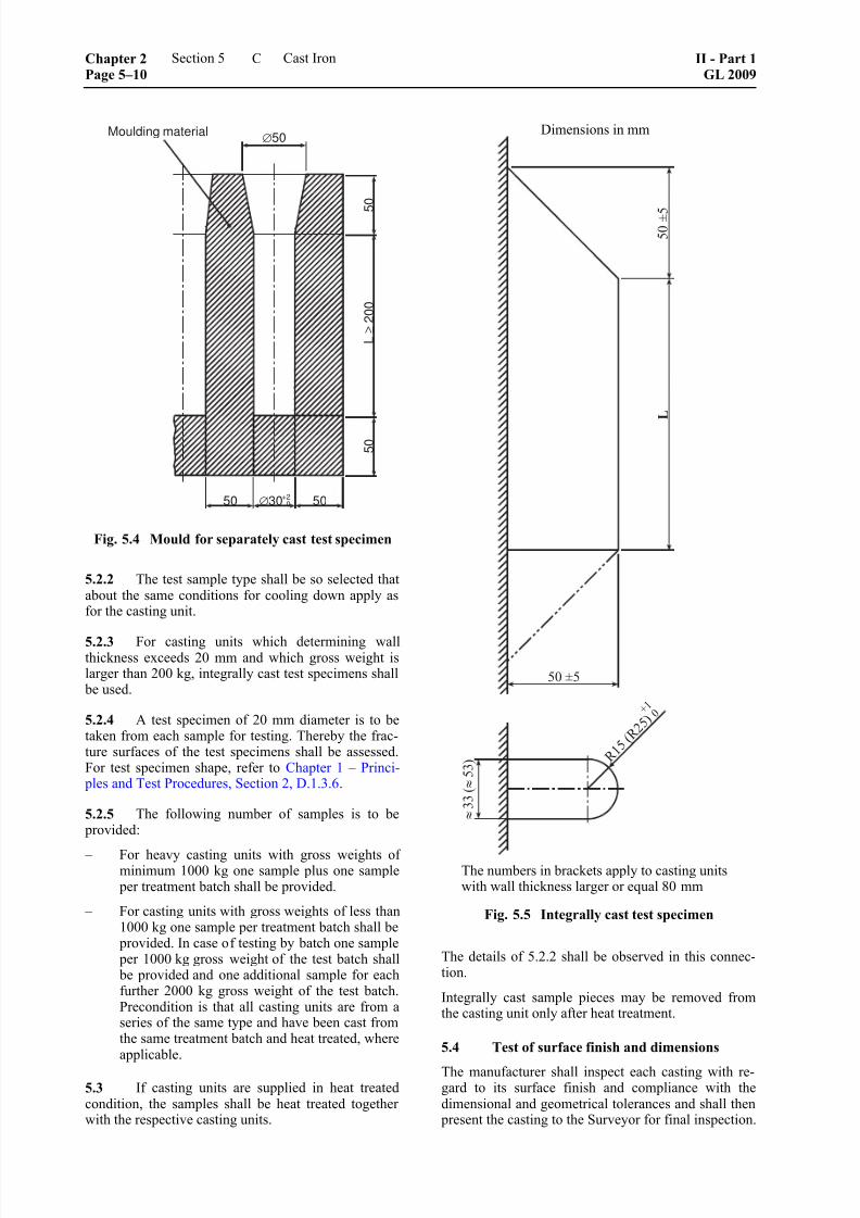
8/10/2019 Casting Material for Shipyards Etc
http://slidepdf.com/reader/full/casting-material-for-shipyards-etc 140/150
8/10/2019 Casting Material for Shipyards Etc
http://slidepdf.com/reader/full/casting-material-for-shipyards-etc 141/150
Section 6
Fittings and Pressed Parts, Bolts and Nuts
A. Pressed Parts
1. Scope
1.1 These Rules are applicable to the testing of pressed parts for pressure vessels, e.g. pressed headsand shell components fabricated from ferritic or aus-tenitic steel plates by hot forming or by cold formingfollowed by heat treatment. They are also applicableto the method of heat treatment which may be required
after forming has been carried out.
1.2 These Rules are also applicable to pressed parts made from individual parts by welding and sub-sequent forming. Testing of these welded joints beforeand after forming is to be carried out according to GLRules Part 3 – Welding.
2. Requirements to be met by manufacturers
Manufacturers wishing to supply products in accor-dance with these Rules shall be approved by GL. This
is conditional upon their fulfilling the manufacturing
and quality control requirements specified in Chapter 1
– Principles and Test Procedures, Section 1, C. and furnishing proof of this to GL prior to the commence-ment of supplies. Tests of product suitability shall additionally be performed on selected products.
3. Requirements applicable to the startingplates
3.1 The grades of steel from which the starting plates are made shall be specified in the order. Inselecting them, care shall be taken to ensure that theyfulfil the requirements to be met by the base materialconcerned after forming and, where applicable, heattreatment.
3.2 The plates may be supplied in the stipulatedfinal heat-treated condition or in another conditionwhich facilitates the subsequent forming. In the lattercase, testing of the starting plates - if required - shall
be performed using test specimens which have under-gone the heat treatment intended for the finished part.The condition of supply of the plates and the methodof heat treatment of the test specimens shall be indi-cated in the test certificate.
4. Dimensions, dimensional and geometrical
tolerances
These are governed by the relevant standards and/orthe information in the order documents. The manufac-turer shall keep relevant documents ready for the test-ing.
5. Principles governing hot forming and heattreatment
5.1 The manufacturer of the finished part shallhave available suitable equipment for the proper exe-cution of the necessary heat treatments. Preliminary
proof of this shall be submitted to the Surveyor.
5.2 The heat treatment equipment shall be fittedwith a sufficient number of calibrated temperature
measuring devices, and fixed items of plant shall beadditionally equipped with automatic recording in-struments which are to be recalibrated at regular inter-vals.
5.3 As far as possible, all parts shall be heated orannealed in their entirety. With the consent of theSurveyor, this Rule may be waived where only localforming is performed. In these cases the heat treatmentshall, however, embrace the whole area of deforma-tion.
5.4 The temperatures, holding times and heating
and cooling rates shall be determined by reference tothe data contained in the standards or manufacturer'sspecifications in accordance with the material and thecomponent concerned. The manufacturer is required toguarantee compliance with the conditions.
5.5 Where the testing of finished parts is allowedto be carried out on separate test sections, provisionshall be made to ensure that these receive the sameheat treatment as the finished part. For this purpose,the test sections shall be laid on top of the correspond-ing finished parts for the annealing operation.
6. Heat treatment after hot forming
6.1 Ferritic steels
6.1.1 Hot forming shall normally be followed byrenewed heat treatment as prescribed for the basematerial concerned.
This Rule may be waived in the case of normalizedand air-quenched and tempered steels with the excep-tion of the steels tough at sub-zero temperatures, pro-vided that the hot forming operation is begun andended within the temperature range specified for this
purpose in the standard or the manufacturer's material
specification. In this case, the renewed heat treatmentcan be dispensed with for normalized steels whiletempering can suffice for air quenched and temperedsteels.
II - Part 1GL 2009
Section 6 Fittings and Pressed Parts, Bolts and Nuts Chapter 2Page 6–1
A

8/10/2019 Casting Material for Shipyards Etc
http://slidepdf.com/reader/full/casting-material-for-shipyards-etc 142/150
6.1.2 For the steels tough at sub-zero temperatures, preliminary proof shall be furnished that the intendedheat treatment imparts to the finished part the neces-sary impact energy at the specified test temperature. Ifthis is the case, then, subject to the conditions men-
tioned in 6.1.1, subsequent heat treatment may bedispensed with for normalized steels, while subse-quent tempering may suffice for air quenched andtempered (normalized and tempered) steels, and in thecase of 5 % and 9% nickel steels calling for triple heattreatments (12 Ni 19 and X 8 Ni 9), the second nor-malizing and tempering operation may be sufficient.
6.1.3 For water-quenched and tempered steels, thenature of the heat treatment to be applied after hotforming shall be specially determined.
6.1.4 The exceptional provisions set out in 6.1.1and 6.1.2 may also be applied where local hot forming
is performed, provided that, prior to forming, the plates were in a heat-treated condition appropriate tothe material.
6.2 Austenitic steels 1
After hot forming, parts made of austenitic steels shall be subjected to renewed heat treatment which shall
normally comprise solution annealing and quenching.
This Rule may be waived where the forming operation
is begun in the temperature range from 1150 to
1000 °C and is ended above 750 °C for stabilized
steels and steels with a carbon content of C ≤ 0,03 %
or above 875 °C for non-stabilized steels with a car- bon content of C ≤ 0,08, followed by rapid cooling to
ambient temperature.
6.3 Clad plates
Where parts are made of clad plates, the nature of theheat treatment is governed by the base material, see6.1. Where the cladding material requires a heattreatment different from that of the base material, thedetails of this shall be specified by the manufacturer ofthe material and made known to GL.
7. Heat treatment after cold forming
7.1 Ferritic steels
All plates shall be in the prescribed condition of sup- ply before cold forming is carried out, see the individ-ual Rules in Section 1. Due to the changes in material
properties which may result from cold forming andageing, the following procedure applies:
7.1.1 Pressed parts for pressure vessels operated at
ambient temperatures or feedstock temperatures down
to – 10 °C shall, if the degree of deformation exceeds
5 % (wall thickness s > 0,05 ⋅ Dm for cylindrical shell
rings and sphere segments), be subjected to heat
––––––––––––––1 For further details on heat treatment of austenitic steels, see
AD-Merkblatt (AD Data Sheet) HP/7.3.
treatment (normalizing or quenching and tempering)
in accordance with the relevant standards or materialspecifications.
7.1.2 Pressed parts for pressure vessels operated at
charging media temperatures below – 10 °C shall,
– if the degree of deformation exceeds 2 % in thecase of steel grades conforming to EN 10028-2,EN 10028-3, EN 10028-4 and EN 10028-6, withthe exception of 12Ni14, 12Ni19, X7Ni9 andX8Ni9,
– if the degree of deformation exceeds 5 % in thecase of steel grades 12Ni14, 12Ni19, X7Ni9 andX8Ni9 conforming to EN 10028-4,
be subjected to heat treatment (normalizing or quench-ing and tempering) in accordance with the relevantstandards or material specifications.
7.1.3 Pressed parts for gas tanks with design tem- peratures below 0 °C shall be treated in accordancewith 7.1.2.
7.1.4 Cold-formed heads, including those fabri-cated from welded round blanks, shall be heat treated(normalized or quenched and tempered) in accordancewith the relevant standards or material specifications.
7.1.5 The stipulations of 7.1.1, 7.1.2 and 7.1.4 may be relaxed if proof is furnished that the properties ofthe materials make them able to withstand the stresses
prevailing while the pressure vessel is in service.
7.1.6 Cold-formed dished heads made of steelgrades S235 JR, S235 J0, S235 J2 and S235 J2+N
according to EN 10025-2, P235 GH and P265 GH to
EN 10028-2, P275 N according to EN 10028-3, as
well as of other steel grades of comparable strength,
do not require heat treatment if the temperature of the
charging media is –10 °C or above, the design tem- perature does not exceed 120 °C according to GL
Construction Rules and the nominal wall thickness is
≤ 8 mm.
7.1.7 If the acceptable degrees of deformation areexceeded in cold forming, heat treatment shall as arule be performed before welding.
7.1.8 In the case of clad pressure vessels or pres-sure vessel components, heat treatment shall be per-formed in accordance with the base material, unlessspecial conditions have to be agreed with regard to thecladding.
7.2 Austenitic steels
7.2.1 Acceptable heat treatments are solution an-
nealing with quenching or, for stabilized steels (excep-tion: Mo-alloyed stabilized steels with more than
0,03 % C) and steels with carbon contents of
C ≤ 0,03 %, stabilization annealing.
Chapter 2Page 6–2
Section 6 Fittings and Pressed Parts, Bolts and Nuts II - Part 1GL 2009
A

8/10/2019 Casting Material for Shipyards Etc
http://slidepdf.com/reader/full/casting-material-for-shipyards-etc 143/150
Note
See AD Data Sheet HP 7/3.
7.2.2 Heat treatment of solution annealed and
quenched or stabilization annealed material after coldforming may be dispensed with if:
7.2.2.1 in the case of austenitic steels with required
minimum elongation values A of ≥ 30 % in respect ofthe initial material, the degree of deformation does notexceed 15 % or proof is furnished that the residualelongation capacity A after cold forming is at least15 %. For size ranges in which the required minimumelongation values A are less than 30 %, proof that theresidual elongation capacity A is 15 % is deemed to
have been furnished if an elongation A of ≥ 30 % isshown in the acceptance test certificate;
7.2.2.2 in the case of degrees of deformation higherthan 15 %, proof is furnished that the residual elonga-tion capacity A after cold forming is at least 15 %;
7.2.2.3 in the case of dished, ellipsoidal and hemi-spherical heads, the following elongations A areshown in the acceptance test certificates for the start-ing materials:
– ≥ 40 % for nominal wall thicknesses ≤ 15 mm atdesign temperatures down to –196 °C,
– ≥ 45 % for nominal wall thicknesses > 15 mm at
design temperatures down to –196 °C,
– ≥ 50 % at design temperatures below –196 °C;
7.2.2.4 in the case of pressure vessel components,except heads, which are operated at design tempera-tures below –196 °C, the degree of deformation doesnot exceed 10 %.
7.3 Clad plates
Cold-formed finished parts made of clad plates aresubject to the conditions stated in 7.1 for the base
material concerned.
8. Testing
8.1 Test of mechanical and technologicalproperties
8.1.1 The testing of pressed parts shall comprisetensile and notched bar impact tests performed onspecimens taken from the finished parts after thefinal heat treatment transverse to the original rollingdirection of the plate. A tolerance of up to 20° fromthe required specimen orientation can be tolerated.
The necessary test sections, the quantity of which isspecified in Table 6.1, shall be taken from surplusmaterial at the edges of the pressed parts or from cut-outs.
8.1.2 Where stress relief heat treatment is sufficientafter forming, the test section may be removed fromthe test piece beforehand and subjected to the sameannealing treatment.
8.1.3 Where Table 6.1 specifies testing by test batches, a test batch may only comprise items madefrom plates originating from the same heat which have
been pressed and heat treated in the same way. Thewall thicknesses of items within a test batch may vary
by 20 % from the mean wall thickness. The number ofsets of specimens shall be determined as follows:
– up to 10 items: 1 set of specimens
– up to 25 items: 2 sets of specimens
– over 25 items: 3 sets of specimens.
8.1.4 Where individual testing of the pressed parts
is prescribed, testing of the starting material by GLmay be dispensed with.
8.1.5 Instead of individual testing of the pressed parts, GL may agree to testing by rolled plate (1 set ofspecimens per starting plate) provided that the manu-facturer of the pressed parts demonstrates to GL by a
preliminary test of the manufacturing method usedthat the requirements can be met and products withconstant characteristics can be manufactured. In thiscase, the starting plates shall be tested.
8.2 Test of surface finish and dimensions
The surface finish and dimensions of each finished part shall be checked by the manufacturer. The partsshall then be submitted to the Surveyor for final test-ing and verification of the dimensions.
For this purpose, the manufacturer shall give the Sur-veyor the measuring records.
9. Marking
Each part shall be marked by the manufacturer withthe manufacturer's mark, the material designation, theheat number and the specimen number.
10. Certificates
10.1 In the case of pressed parts which are heattreated after forming, the manufacturer shall certifythe proper execution of the heat treatment stating thetemperatures, the holding times and the type of cool-ing applied.
10.2 In the case of pressed parts which may besupplied in the hot pressed condition, the manufac-turer shall certify that the forming operation was be-gun and ended within the specified temperature limits
and shall indicate the standard or material specifica-tion applicable. In addition, the method of cooling andthe condition in which the starting material was sup-
plied shall also be stated.
II - Part 1GL 2009
Section 6 Fittings and Pressed Parts, Bolts and Nuts Chapter 2Page 6–3
A

8/10/2019 Casting Material for Shipyards Etc
http://slidepdf.com/reader/full/casting-material-for-shipyards-etc 144/150

8/10/2019 Casting Material for Shipyards Etc
http://slidepdf.com/reader/full/casting-material-for-shipyards-etc 145/150

8/10/2019 Casting Material for Shipyards Etc
http://slidepdf.com/reader/full/casting-material-for-shipyards-etc 146/150
Table 6.3 Classification into test groups and scope of tests
Scope of tests per test batch
Test
groups
Size
da
[mm]
Material Hardness
test 1 Tensile test
Notched bar
impact test2
(set of specimens
= 3 specimens)
I < 100 unalloyed 1 4
II < 100 alloyed 1 4
III ≥ 100
unalloyed
R m < 500
N/mm2
10 % 3
min. on
3 fittings
IV
≥ 100
≤ 225
(DN ≤ 200)
unalloyed
R m ≥ 500
N/mm2
10 % min. on
3 fittings
V> 225
(DN > 200)
or
alloyed100 % 5
2 specimens,
only if less than
10 fittings
1 specimen
2 sets,
only if less than
10 fittings
1 set
1 With austenitic steels, the hardness test is dispensed with if the geometry allows tensile tests to be performed.
2 The notched bar impact test is only performed in the case of materials for which minimum values for the absorbed energy are stated for
the starting material. Furthermore, specimens are only taken where the wall thickness is ≥ 6 mm and the geometry allows this to be
done.
3 Starting with the second batch of a complete final inspection, the scope of hardness testing may be reduced by half if the hardness
values measured for the first batch lie within the specified strength range.
4 The tensile test is to be carried out on the starting pipe.
5 For elbows made of 16 Mo 3, 13 Cr Mo 4-5 and 10 Cr Mo 9-10 conforming to EN 10028-2, the scope of hardness testing specified
for test group IV is applicable.
C. Bolts and Nuts
1. Scope
1.1 These Rules are applicable to the manufac-ture, the mechanical properties and the testing of boltsand nuts for
– boilers, vessels, equipment and pipelines
– diesel engines, gears, shafting and propellers
– other components of the machinery plant forwhich proof of quality is required as specified inthe Construction Rules
1.2 The choice of bolts and nuts, together withthe form of the requisite material test certificate is setout in the individual Chapters of the ConstructionRules and shall be stated in the purchase order.
2. Materials
2.1 Bolts and nuts are to be selected in accor-dance with recognized standards or the manufacturer'smaterial specifications which have been approved by
GL. The steels used in the manufacture of bolts shallhave a guaranteed impact energy. Under these condi-tions, the following materials may be considered:
2.1.1 Bolts and nuts conforming to ISO 898(EN 20898-1 and -2) up to M39 threads. Exemptedthereof are bolts of strength categories for which thestandard gives no data in respect of impact energy.
2.1.2 Steels conforming to EN 10269 in conjunc-tion with DIN 267-13.
2.1.3 Steels conforming to DIN 267-13.
2.1.4 Stainless steels conforming to ISO 3506-1and -2.
2.2 Bolts and nuts conforming to other standardsor the manufacturer’s material specifications may beused, provided that GL has confirmed their suitabilityfor the intended application. Unless otherwise speci-fied, the materials shall satisfy the requirements of
4.2.2, 4.2.3 and 4.2.4.
2.3 Free cutting steels with a high sulphur, phos- phorous or lead content may not be used.
Chapter 2Page 6–6
Section 6 Fittings and Pressed Parts, Bolts and Nuts II - Part 1GL 2009
C
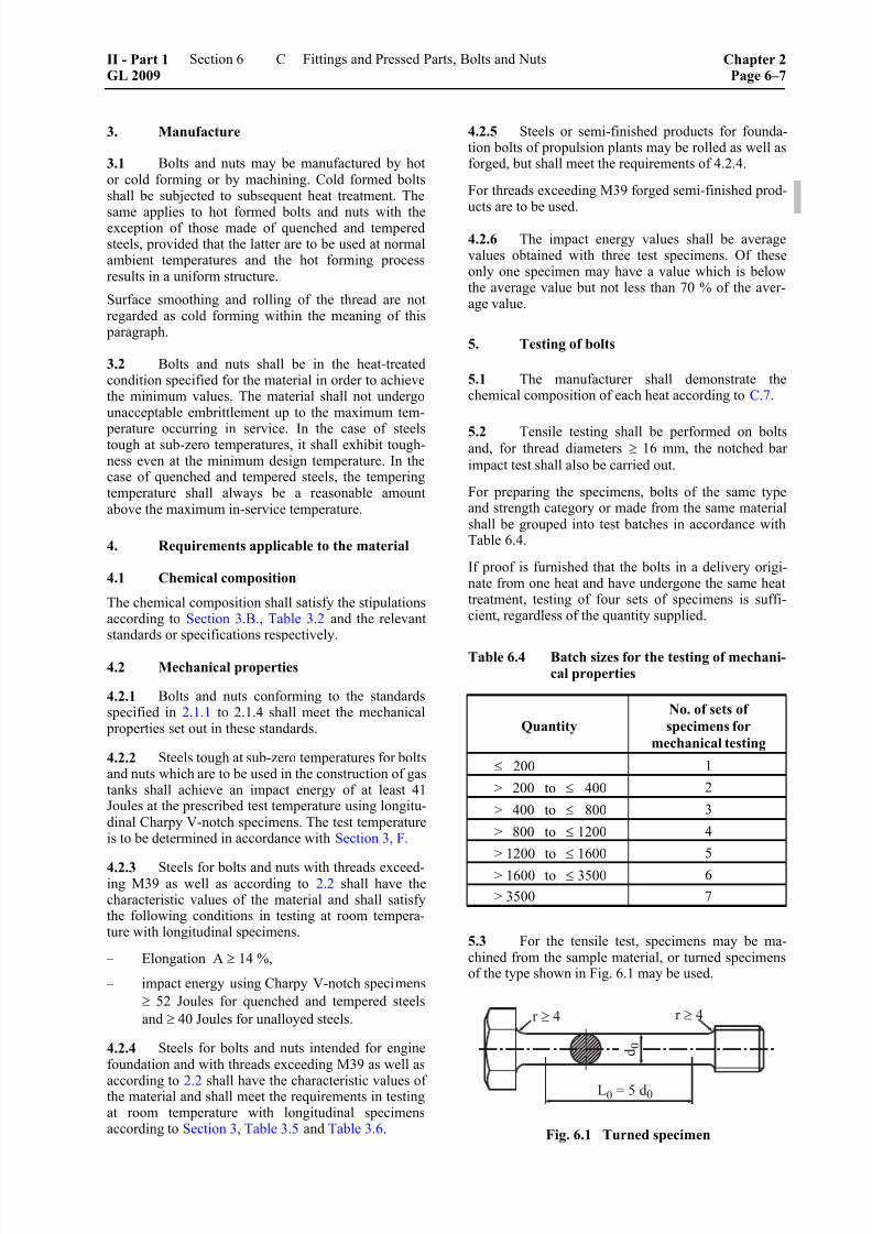
8/10/2019 Casting Material for Shipyards Etc
http://slidepdf.com/reader/full/casting-material-for-shipyards-etc 147/150
3. Manufacture
3.1 Bolts and nuts may be manufactured by hotor cold forming or by machining. Cold formed boltsshall be subjected to subsequent heat treatment. The
same applies to hot formed bolts and nuts with theexception of those made of quenched and temperedsteels, provided that the latter are to be used at normalambient temperatures and the hot forming processresults in a uniform structure.
Surface smoothing and rolling of the thread are notregarded as cold forming within the meaning of this
paragraph.
3.2 Bolts and nuts shall be in the heat-treatedcondition specified for the material in order to achievethe minimum values. The material shall not undergounacceptable embrittlement up to the maximum tem-
perature occurring in service. In the case of steelstough at sub-zero temperatures, it shall exhibit tough-ness even at the minimum design temperature. In thecase of quenched and tempered steels, the temperingtemperature shall always be a reasonable amountabove the maximum in-service temperature.
4. Requirements applicable to the material
4.1 Chemical composition
The chemical composition shall satisfy the stipulationsaccording to Section 3.B., Table 3.2 and the relevantstandards or specifications respectively.
4.2 Mechanical properties
4.2.1 Bolts and nuts conforming to the standardsspecified in 2.1.1 to 2.1.4 shall meet the mechanical
properties set out in these standards.
4.2.2 Steels tough at sub-zero temperatures for bolts
and nuts which are to be used in the construction of gas
tanks shall achieve an impact energy of at least 41
Joules at the prescribed test temperature using longitu-dinal Charpy V-notch specimens. The test temperature
is to be determined in accordance with Section 3, F.
4.2.3 Steels for bolts and nuts with threads exceed-ing M39 as well as according to 2.2 shall have thecharacteristic values of the material and shall satisfythe following conditions in testing at room tempera-ture with longitudinal specimens.
– Elongation A ≥ 14 %,
– impact energy using Charpy V-notch specimens
≥ 52 Joules for quenched and tempered steels
and ≥ 40 Joules for unalloyed steels.
4.2.4 Steels for bolts and nuts intended for enginefoundation and with threads exceeding M39 as well as
according to 2.2 shall have the characteristic values ofthe material and shall meet the requirements in testingat room temperature with longitudinal specimensaccording to Section 3, Table 3.5 and Table 3.6.
4.2.5 Steels or semi-finished products for founda-tion bolts of propulsion plants may be rolled as well asforged, but shall meet the requirements of 4.2.4.
For threads exceeding M39 forged semi-finished prod-ucts are to be used.
4.2.6 The impact energy values shall be averagevalues obtained with three test specimens. Of theseonly one specimen may have a value which is belowthe average value but not less than 70 % of the aver-age value.
5. Testing of bolts
5.1 The manufacturer shall demonstrate thechemical composition of each heat according to C.7.
5.2 Tensile testing shall be performed on boltsand, for thread diameters ≥ 16 mm, the notched bar
impact test shall also be carried out.
For preparing the specimens, bolts of the same typeand strength category or made from the same materialshall be grouped into test batches in accordance withTable 6.4.
If proof is furnished that the bolts in a delivery origi-nate from one heat and have undergone the same heattreatment, testing of four sets of specimens is suffi-cient, regardless of the quantity supplied.
Table 6.4 Batch sizes for the testing of mechani-
cal properties
Quantity
No. of sets of
specimens for
mechanical testing
≤ 200 1
> 200 to ≤ 400 2
> 400 to ≤ 800 3
> 800 to ≤ 1200 4
> 1200 to ≤ 1600 5
> 1600 to ≤ 3500 6
> 3500 7
5.3 For the tensile test, specimens may be ma-chined from the sample material, or turned specimensof the type shown in Fig. 6.1 may be used.
Fig. 6.1 Turned specimen
II - Part 1GL 2009
Section 6 Fittings and Pressed Parts, Bolts and Nuts Chapter 2Page 6–7
C

8/10/2019 Casting Material for Shipyards Etc
http://slidepdf.com/reader/full/casting-material-for-shipyards-etc 148/150
5.4 Where no heat treatment is performed follow-ing machining and the starting material is in the finalheat treated condition, testing of the starting materialwith regard to demonstrating mechanical propertiesshall suffice. In this case steel bars from the same heat
and with the same diameter and heat treatment are to be grouped into test batches of 5000 kg maximum.The performance of the tensile and notched bar impacttests require one set of test specimens to be taken fromeach test batch.
5.5 Where machining is followed by heat treat-ment, testing shall be performed in the same way as onthe corresponding formed bolts as per 5.2.
5.6 The surface finish, dimensions and compli-ance with tolerances shall be verified by the Surveyoron at least 20 bolts and on at least 10 bolts in the case
of batch sizes of≤
200. The manufacturer shall supplythe gauges and callipers necessary for this purpose.
5.7 The uniformity of the delivery is to be dem-
onstrated by the manufacturer by means of hardnesstests. For this purpose, at least 20 bolts from each test
batch are to be tested, and at least 10 bolts in the case
of quantities ≤ 200. The results of the test are to be
submitted to the Surveyor.
5.8 For bolts calculated for elevated temperatureapplication on the basis of their high-temperaturemechanical characteristics, the 0,2 % or 1 % proof
stress shall be proved by a high-temerature tensile test performed on one specimen from each batch. The testshall be performed at the temperature which approxi-mates most closely to the level of the operating tem-
perature, rounded off to the nearest 50 °C. The testmay be dispensed with in the case of bolts to recog-nized standards, the high-temperature mechanical
properties of which are regarded as proven.
6. Testing of nuts
6.1 Chemical composition
The chemical composition shall satisfy the stipulations
according to Section 3, B., Table 3.2 and the relevantstandards or specifications respectively.
6.2 Nuts with nominal thread diameters of up to
and including 39 mm are to be subjected to the expan-
sion test using a mandrel with a 1:100 taper, see Fig.
6.2. Before testing, the nuts are to be drilled out to the
thread outside diameter. The expansion shall be at
least 6 % for nuts with a depth of ≥ 0,8 ⋅ nominal
thread diameter d (at least 4 % for nuts with a depth of
≥ 0,5 to < 0,8 d). The numbers of test specimens
shown in Table 6.4 are applicable, but for quantities of
≤ 200 at least 2 nuts shall be tested.
6.3 Nuts with nominal thread diameters > 39 mm
are to be subjected to testing of the starting material as
specified in 5.2 rather than the expansion test.
Fig. 6.2 Expansion testing of nuts
Chapter 2Page 6–8
Section 6 Fittings and Pressed Parts, Bolts and Nuts II - Part 1GL 2009
C

8/10/2019 Casting Material for Shipyards Etc
http://slidepdf.com/reader/full/casting-material-for-shipyards-etc 149/150

8/10/2019 Casting Material for Shipyards Etc
http://slidepdf.com/reader/full/casting-material-for-shipyards-etc 150/150