Carbon Nanotubes for Supercapacitor - Nanoscale Research Letters
15
NANO REVIEW Carbon Nanotubes for Supercapacitor Hui Pan • Jianyi Li • Yuan Ping Feng Received: 7 June 2009 / Accepted: 9 December 2009 / Published online: 5 January 2010 Ó The Author(s) 2009. This article is published with open access at Springerlink.com Abstract As an electrical energy storage device, sup- ercapacitor finds attractive applications in consumer elec- tronic products and alternative power source due to its higher energy density, fast discharge/charge time, low level of heating, safety, long-term operation stability, and no disposable parts. This work reviews the recent develop- ment of supercapacitor based on carbon nanotubes (CNTs) and their composites. The purpose is to give a compre- hensive understanding of the advantages and disadvantages of carbon nanotubes-related supercapacitor materials and to find ways for the improvement in the performance of supercapacitor. We first discussed the effects of physical and chemical properties of pure carbon nanotubes, including size, purity, defect, shape, functionalization, and annealing, on the supercapacitance. The composites, including CNTs/oxide and CNTs/polymer, were further discussed to enhance the supercapacitance and keep the stability of the supercapacitor by optimally engineering the composition, particle size, and coverage. Keywords Carbon nanotubes Supercapacitor Oxide/nanotube composite Polymer/nanotube composite Introduction Electrical energy storage is required in many applications demanding local storage or local generation of electric energy. A storage device to be suitable for a particular application must meet all the requirements in terms of energy density (Wh) and maximum power (W) as well as size, weight, initial cost and life, etc. Supercapacitors fill in the gap between batteries and conventional capacitors, covering several orders of magnitude both in energy and in power densities. They are an attractive choice for the energy storage applications in portable or remote appara- tuses where batteries and conventional capacitors have to be over-dimensioned due to unfavorable power-to-energy ratio [1, 2]. In electric, hybrid electric, and fuel cell vehi- cles, supercapacitors will serve as a short-time energy storage device with high power capability and allow stor- ing the energy from regenerative braking. Increasing applications also appear in telecommunications such as cellular phones and personal entertainment instruments. An ultracapacitor or supercapacitor can be viewed as two nonreactive porous plates, or electrodes, immersed in an electrolyte, with a voltage potential applied across the collectors. A porous dielectric separator between the two electrodes prevents the charge from moving between the two electrodes (Fig. 1). Supercapacitors are generally classified into two types: pseudocapacitor and electric- double-layer capacitor. The electrical charge can be built up in the pseudocapacitor via an electron transfer that produces the changes in chemical or oxidization state in the electroactive materials according to Faraday’s laws related to electrode potential, that is, the basis of energy storage in pseudocapacitor is Faradaic charge transfer. The charge process in the electric-double-layer capacitor (EDLC) is non-Faradaic, i.e. ideally no electron transfer takes place H. Pan Y. P. Feng Department of Physics, National University of Singapore, Singapore 117542, Singapore H. Pan (&) Institute of High Performance Computing, 1 Fusionopolis Way, Singapore 138632, Singapore e-mail: [email protected] J. Li Institute of Chemical and Engineering Sciences, 1 Pesek Road, Jurong Island, Singapore 627833, Singapore 123 Nanoscale Res Lett (2010) 5:654–668 DOI 10.1007/s11671-009-9508-2
Transcript of Carbon Nanotubes for Supercapacitor - Nanoscale Research Letters
NANO REVIEW
Carbon Nanotubes for Supercapacitor
Hui Pan • Jianyi Li • Yuan Ping Feng
Received: 7 June 2009 / Accepted: 9 December 2009 / Published online: 5 January 2010
� The Author(s) 2009. This article is published with open access at Springerlink.com
Abstract As an electrical energy storage device, sup-
ercapacitor finds attractive applications in consumer elec-
tronic products and alternative power source due to its
higher energy density, fast discharge/charge time, low level
of heating, safety, long-term operation stability, and no
disposable parts. This work reviews the recent develop-
ment of supercapacitor based on carbon nanotubes (CNTs)
and their composites. The purpose is to give a compre-
hensive understanding of the advantages and disadvantages
of carbon nanotubes-related supercapacitor materials and
to find ways for the improvement in the performance of
supercapacitor. We first discussed the effects of physical
and chemical properties of pure carbon nanotubes,
including size, purity, defect, shape, functionalization, and
annealing, on the supercapacitance. The composites,
including CNTs/oxide and CNTs/polymer, were further
discussed to enhance the supercapacitance and keep the
stability of the supercapacitor by optimally engineering the
composition, particle size, and coverage.
Keywords Carbon nanotubes � Supercapacitor �Oxide/nanotube composite � Polymer/nanotube composite
Introduction
Electrical energy storage is required in many applications
demanding local storage or local generation of electric
energy. A storage device to be suitable for a particular
application must meet all the requirements in terms of
energy density (Wh) and maximum power (W) as well as
size, weight, initial cost and life, etc. Supercapacitors fill in
the gap between batteries and conventional capacitors,
covering several orders of magnitude both in energy and in
power densities. They are an attractive choice for the
energy storage applications in portable or remote appara-
tuses where batteries and conventional capacitors have to
be over-dimensioned due to unfavorable power-to-energy
ratio [1, 2]. In electric, hybrid electric, and fuel cell vehi-
cles, supercapacitors will serve as a short-time energy
storage device with high power capability and allow stor-
ing the energy from regenerative braking. Increasing
applications also appear in telecommunications such as
cellular phones and personal entertainment instruments.
An ultracapacitor or supercapacitor can be viewed as
two nonreactive porous plates, or electrodes, immersed in
an electrolyte, with a voltage potential applied across the
collectors. A porous dielectric separator between the two
electrodes prevents the charge from moving between the
two electrodes (Fig. 1). Supercapacitors are generally
classified into two types: pseudocapacitor and electric-
double-layer capacitor. The electrical charge can be built
up in the pseudocapacitor via an electron transfer that
produces the changes in chemical or oxidization state in the
electroactive materials according to Faraday’s laws related
to electrode potential, that is, the basis of energy storage in
pseudocapacitor is Faradaic charge transfer. The charge
process in the electric-double-layer capacitor (EDLC) is
non-Faradaic, i.e. ideally no electron transfer takes place
H. Pan � Y. P. Feng
Department of Physics, National University of Singapore,
Singapore 117542, Singapore
H. Pan (&)
Institute of High Performance Computing, 1 Fusionopolis Way,
Singapore 138632, Singapore
e-mail: [email protected]
J. Li
Institute of Chemical and Engineering Sciences, 1 Pesek Road,
Jurong Island, Singapore 627833, Singapore
123
Nanoscale Res Lett (2010) 5:654–668
DOI 10.1007/s11671-009-9508-2
across the electrode interface and the storage of electric
charge and energy is electrostatic [1]. However, the EDLC
with various high-area carbon electrodes also exhibit a
small but significant pseudocapacitance due to electro-
chemically active redox functionalities.
The electrical energy (E) accumulated in a supercapac-
itor is related to the capacitance (C) or the stored charges
(Q) and voltage (V) by following formula:
E ¼ CV2
2¼ QV
2: ð1Þ
The capacitance and stored charge depend essentially on
the electrode material used, whereas the operating voltage
is determined by the stability window of the electrolyte.
The use of high-capacitance materials is a key factor for
the improvement in the energy density. Generally, the
supercapacitor can provide higher power than most
batteries, because a large amount of charges (Q) can be
stored in the double layers. But, the power density, as
indicated in the following formula, is relatively low
because of the series resistance.
P ¼ V2
4RSð2Þ
where Rs represents the equivalent series resistance (ERS) of
the two electrodes. The improvement in the power and power
density requires the development of materials with high
capacitance and low resistance, as indicated in Eqs. 1 and 2.
A variety of materials, including oxide, polymer, carbon
and their composites, can be used as the electrodes of
supercapacitor. Pseudocapacitor utilizes conducting poly-
mers (such as, polyacetylene, polypyrrole, and polyaniline
[3–12]), metal oxides (such as RuO2 and Co3O4 [13–27]),
or polymer-oxide composite [26, 28] as electrode materi-
als. The chemical or oxidization state changes in the
electrodes induced by the Faradiac charge transfer in the
pseudocapactive behavior may affect the cycling stability
and limit their application due to high resistance and poor
stability, although the specific capacitance of RuO2�0.5H2O
can be as high as 900 F/g [29]. EDLC normally is devel-
oped using porous carbon materials (such as activated
carbon) as electrode, and the electrical charge is electro-
statically accumulated at the electrode/electrolyte interface
[30–42]. Carbon aerogel (CA) or other types of carbon
materials such as carbon black or carbon cloth are widely
used in these supercapacitors. Generally, high surface area
in carbon materials is characteristic of highly developed
microporous structure, which is however unfavorable for
the electrolyte wetting and rapid ionic motions, especially
at high current loads. The combination of high surface area
carbon aerogel with large specific capacity of oxide or
polymer would result in high power and power density, and
stability by utilizing both the faradaic capacitance of the
metal oxide or polymer and the double-layer capacitance of
the carbon [43–46].
Carbon nanotubes (CNTs) have been widely studied
since their discovery in 1991 [47] and attracted extensive
attention due to their intriguing and potentially useful
structural, electrical and mechanical properties. CNTs are
formed when a graphite sheet is curled up into cylinders,
including single-walled CNT (SWCNT) and multi-walled
CNT (MWCNT) [48]. CNTs have a novel structure, a
narrow distribution of size in the nanometer range, highly
accessible surface area, low resistivity, and high stability
[47–52]. These features suggest that CNTs are suitable
materials for polarizable electrodes. Both SWCNTs and
MWCNTs have been studied for electrochemical superca-
pacitor electrodes due to their unique properties [53–59].
On the other hand, composites incorporating a nanotubular
backbone coated by an active phase with pseudocapacitive
properties, such as CNT/oxide composite, represent an
important breakthrough for developing a new generation of
supercapacitors based on three basic reasons [32, 60–64]:
(1) the percolation of the active particles is more efficient
with nanotubes than with the traditional carbon materials;
(2) the open mesoporous network formed by the entan-
glement of nanotubes allows the ions to diffuse easily to
the active surface of the composite components; and (3)
since the nanotubular materials are characterized by a high
resiliency, the composite electrodes can easily adapt to the
volumetric changes during charge and discharge, which
improves drastically the cycling performance. The first two
properties are essential to lower the equivalent series resis-
tance (Rs) and consequently increase the power density.
In this review, we will focus on recent progress on the
CNT-based supercapacitors to investigate the effects of the
CNTs and corresponding composites on the performance of
the supercapacitors and possible ways for the improvement
in the performance. The review is organized into five
sections. The brief introduction to the supercapacitor
is presented in ‘‘Introduction’’. ‘‘Supercapacitor from
CNTs’’ focuses on the pure CNTs-based supercapacitors.
Fig. 1 A presentation of supercapacitor. http://en.wikipedia.org/wiki/
Supercapacitor
Nanoscale Res Lett (2010) 5:654–668 655
123
Supercapacitor from CNT/oxide composite is discussed in
‘‘Supercapacitor from CNT and oxide composite’’. Sup-
ercapacitor from CNT/polymer composite is investigated in
‘‘Supercapacitor from CNT and polymer composite’’.
Finally in ‘‘Summary’’, some concluding remarks are given.
Supercapacitor from CNTs
In 1997, Niu et al. [53] first suggested that CNTs could be
used in supercapacitors. The MWCNTs were functional-
ized in nitric acid with functional groups introduced on the
surface. These functionalized MWCNTs had a specific area
of 430 m2/g, a gravimetric capacitance of 102 F/g and an
energy density of 0.5 W�h/kg obtained at 1 Hz on a single-
cell device, using 38 wt% sulfuric acid as the electrolyte.
Although 90% of the catalyst residue was removed, the
remaining catalyst in the MWCNTs (mainly within the
inner of the tubes) would affect the performance of the
supercapacitor. The pseudocapacitance could be induced
by the functional groups and the remaining catalyst.
Therefore, both of the Faradiac and non-Faradiac processes
were involved in the CNTs-based supercapacitor. The
redox response observed on the cyclic voltammetric (CV)
plot of the SWCNT-based electrodes also indicated that the
pseudocapacitance was really occurred to the CNT-based
capacitor due to the functional groups and impurities [65].
However, it was demonstrated that the performance of the
purified SWCNT, where the catalyst (Fe) was removed by
thermal oxidization followed by immersion in HCl, was not
as great as expected because of the formation of amorphous
carbon by the thermal oxidization [66]. It is difficult to
totally remove the catalyst from the catalyst-assisted CNTs
and keep the graphitization at the same time, and then the
effect of the catalyst is always there. To simplify the dis-
cussion, we firstly focus on the structural properties of
CNTs, such as diameter, length, and pore size, which play
an important role on the EDLC, and discuss the catalyst’s
and functional groups’ effects later.
Effects of Structure
The amount of electrical charge accumulated due to elec-
trostatic attraction in EDLC depends on the area of the
electrode/electrolyte interface that can be accessed by the
charge carriers. The higher surface area of the electrode
material could leads to higher capacitance if the area can be
fully accessed by the charge carriers. However, the higher
surface area does not always result in higher capacitance
because the capacitance also depends on the pore size, the
size distribution and conductivity. Higher capacitance can
be achieved by optimizing all of the related factors. For
example, the vertically aligned CNTs with the diameter of
about 25 nm and a specific area of 69.5 m2/g had a specific
capacitance of 14.1 F/g and showed excellent rate capa-
bility, which were better than those of entangled CNTs due
to the larger pore size, more regular pore structure and
more conductive paths [67, 68].
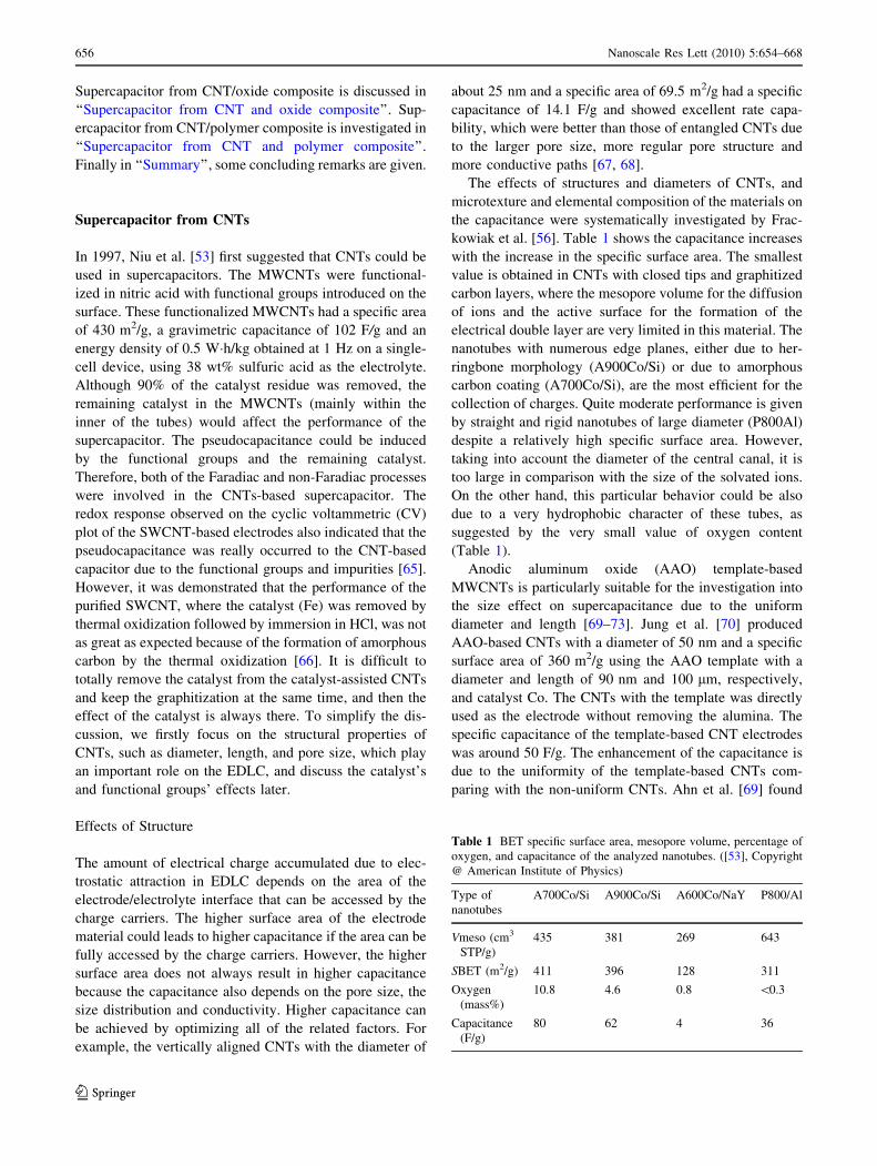
The effects of structures and diameters of CNTs, and
microtexture and elemental composition of the materials on
the capacitance were systematically investigated by Frac-
kowiak et al. [56]. Table 1 shows the capacitance increases
with the increase in the specific surface area. The smallest
value is obtained in CNTs with closed tips and graphitized
carbon layers, where the mesopore volume for the diffusion
of ions and the active surface for the formation of the
electrical double layer are very limited in this material. The
nanotubes with numerous edge planes, either due to her-
ringbone morphology (A900Co/Si) or due to amorphous
carbon coating (A700Co/Si), are the most efficient for the
collection of charges. Quite moderate performance is given
by straight and rigid nanotubes of large diameter (P800Al)
despite a relatively high specific surface area. However,
taking into account the diameter of the central canal, it is
too large in comparison with the size of the solvated ions.
On the other hand, this particular behavior could be also
due to a very hydrophobic character of these tubes, as
suggested by the very small value of oxygen content
(Table 1).
Anodic aluminum oxide (AAO) template-based
MWCNTs is particularly suitable for the investigation into
the size effect on supercapacitance due to the uniform
diameter and length [69–73]. Jung et al. [70] produced
AAO-based CNTs with a diameter of 50 nm and a specific
surface area of 360 m2/g using the AAO template with a
diameter and length of 90 nm and 100 lm, respectively,
and catalyst Co. The CNTs with the template was directly
used as the electrode without removing the alumina. The
specific capacitance of the template-based CNT electrodes
was around 50 F/g. The enhancement of the capacitance is
due to the uniformity of the template-based CNTs com-
paring with the non-uniform CNTs. Ahn et al. [69] found
Table 1 BET specific surface area, mesopore volume, percentage of
oxygen, and capacitance of the analyzed nanotubes. ([53], Copyright
@ American Institute of Physics)
Type of
nanotubes
A700Co/Si A900Co/Si A600Co/NaY P800/Al
Vmeso (cm3
STP/g)
435 381 269 643
SBET (m2/g) 411 396 128 311
Oxygen
(mass%)
10.8 4.6 0.8 \0.3
Capacitance
(F/g)
80 62 4 36
656 Nanoscale Res Lett (2010) 5:654–668
123

that the capacitance of the CNTs with smaller diameter
(33 nm) is larger than that of with larger diameter (200 nm)
due to the larger surface area in smaller diameter CNTs.
Effects of Heating
Heating is one of important ways to improve the graphi-
tization of CNTs and remove the amorphous carbon. The
effects of heating on the capacitance depend on the heating
temperature and the quality of the as-grown CNTs. The
capacitance of as-received SWCNTs (Rice) was about 40
F/g and reduced to 18 F/g after heating treatment at
1,650 �C probably due to the more perfect graphitization of
the tubes [74]. However, Li et al. [75] found that the spe-
cific capacitance was increased by the oxidization up to
650 �C due to the enhanced specific surface area and dis-
persity. But the capacitance decreased with further increas-
ing the temperature due to reduced surface area. At the
same time, the heat treatment led to the reduction in the
equivalent series resistance, resulting in the enhancement
of the power density because of the improvement on
graphitization. Fig. 2 shows the Brunauer-Emmett-Teller
(BET; N2) specific surface area and average pore diameter
of as-grown CNTs as a function of heat-treatment tem-
perature (carried out for 30 min) [54, 76]. With increasing
temperature, the specific surface area increases, whereas
the average pore diameter decreases and saturates at high
temperature. The raw sample shows a peak at 150 A´
and
has less distribution in the smaller pore diameter near 20 A´
.
With increasing heat-treatment temperature, the number of
smaller pore diameters increases and reaches the maximum
at 1,000 �C, whereas the number of pore diameters ranging
from 50 ± 250 A´
decreases. Fig. 3 shows the specific
capacitance as a function of charging time and current, the
CV curves, and impedance plots. A maximum specific
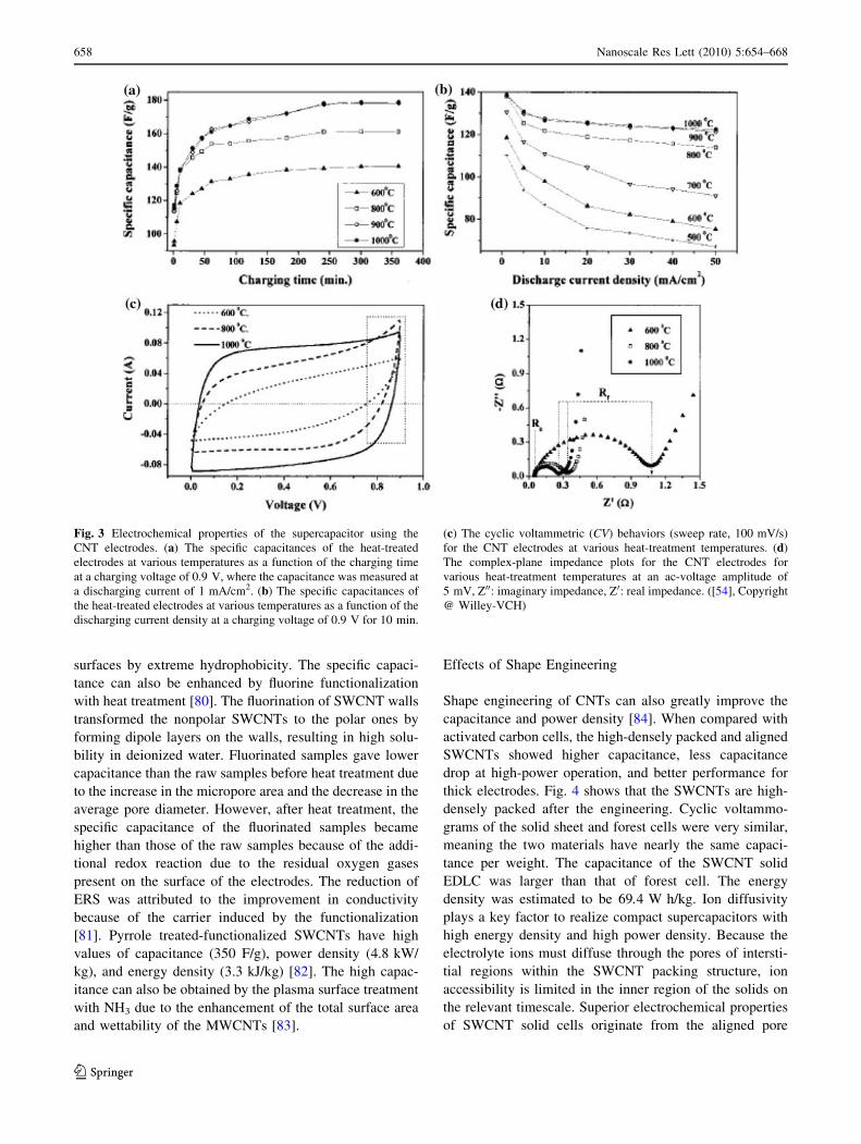
capacitance of 180 F/g and a measured power density of
20 kW/kg for the heat-treated SWCNTs were obtained.
The increased capacitance was well explained by the
enhancement of the specific surface area and the abundant
pore distributions at lower pore sizes.
Effects of Functionalization
Capacitance of CNT-based supercapacitor can also be
enhanced by chemical activation [56, 77, 78], functionali-
zation [79–81], and heat and surface treatment [81, 82].
The value of specific capacitance increased significantly
after strong oxidation in nitride acid due to the increase of
the functional groups on the CNT’s surface [56]. Enhanced
values of capacitance were observed after activation: in
some cases, it increased almost seven times, because the
microporosity of pure MWCNTs can be highly developed
using chemical KOH activation [77]. The activated mate-
rial still possessed a nanotubular morphology with many
defects on the outer walls that gave a significant increase in
micropore volume, while keeping a noticeable mesopo-
rosity. The electrochemical treatment of CNTs provides an
effective and controllable method for changing the pore
size distribution (PSD) of SWCNTs [78]. In particular, a
remarkable volume of the small mesopores in the 3.0–
5.0 nm diameter range was increased. The SWCNTs trea-
ted for 24 h at 1.5 V have a higher specific surface area
(109.4 m2/g) and larger volume of small mesopores
(0.048 cm3/g in 3.0–5.0 nm diameter range), compared
with the as-grown SWCNTs (46.8 m2/g and 0.026 cm3/g,
respectively). The specific capacitance was increased three-
fold after electrochemical treatment. The electric double-
layer capacitance, depending on the surface functional
groups, can be dramatically changed, from a large increase
to complete disappearance [79]. The introduction of sur-
face carboxyl groups created a 3.2 times larger capacitance
due to the increased hydrophilicity of MWCNTs in an
aqueous electrolyte. In contrast, the introduction of alkyl
groups resulted in a marked decrease in capacitance.
Notably, the complete disappearance of capacitance for
samples functionalized with longer alkyl groups, indicating
the perfect block of proton access to the carbon nanotubes’
Fig. 2 (a) The BET (N2) specific surface areas and the average pore
diameters of the CNT electrode as a function of heat-treatment
temperature and (b) The pore size distribution of the CNT electrodes.
([54], Copyright @ Willey-VCH)
Nanoscale Res Lett (2010) 5:654–668 657
123
surfaces by extreme hydrophobicity. The specific capaci-
tance can also be enhanced by fluorine functionalization
with heat treatment [80]. The fluorination of SWCNT walls
transformed the nonpolar SWCNTs to the polar ones by
forming dipole layers on the walls, resulting in high solu-
bility in deionized water. Fluorinated samples gave lower
capacitance than the raw samples before heat treatment due
to the increase in the micropore area and the decrease in the
average pore diameter. However, after heat treatment, the
specific capacitance of the fluorinated samples became
higher than those of the raw samples because of the addi-
tional redox reaction due to the residual oxygen gases
present on the surface of the electrodes. The reduction of
ERS was attributed to the improvement in conductivity
because of the carrier induced by the functionalization
[81]. Pyrrole treated-functionalized SWCNTs have high
values of capacitance (350 F/g), power density (4.8 kW/
kg), and energy density (3.3 kJ/kg) [82]. The high capac-
itance can also be obtained by the plasma surface treatment
with NH3 due to the enhancement of the total surface area
and wettability of the MWCNTs [83].
Effects of Shape Engineering
Shape engineering of CNTs can also greatly improve the
capacitance and power density [84]. When compared with
activated carbon cells, the high-densely packed and aligned
SWCNTs showed higher capacitance, less capacitance
drop at high-power operation, and better performance for
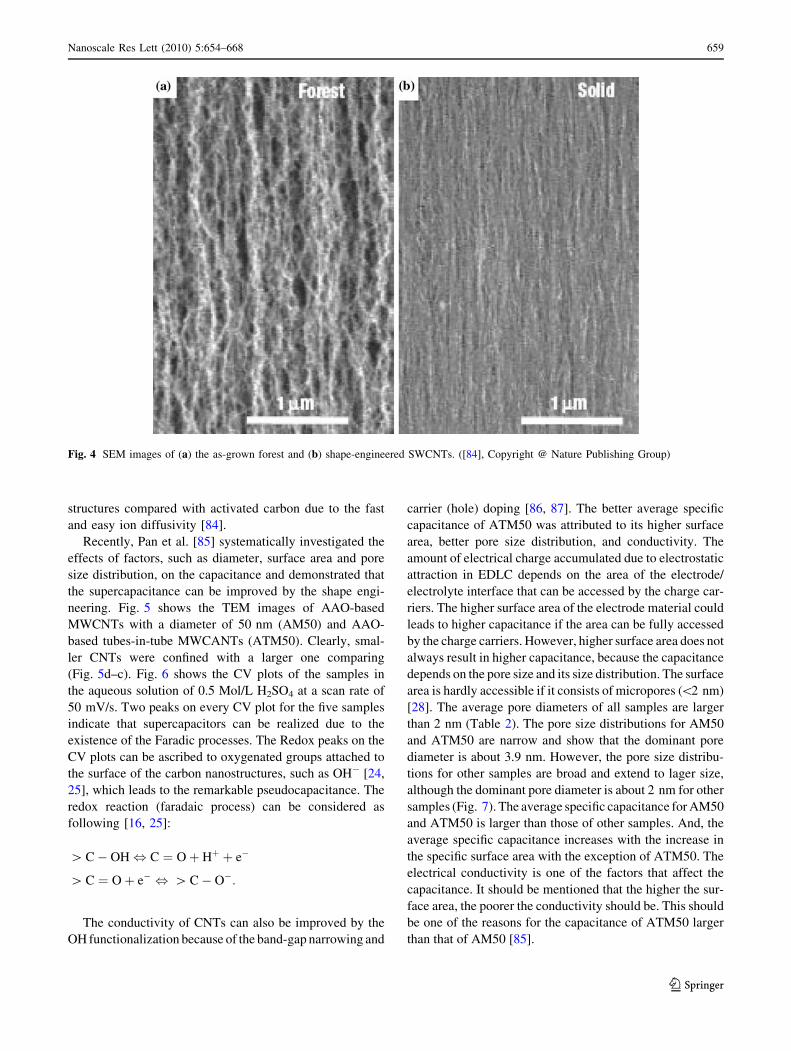
thick electrodes. Fig. 4 shows that the SWCNTs are high-
densely packed after the engineering. Cyclic voltammo-
grams of the solid sheet and forest cells were very similar,
meaning the two materials have nearly the same capaci-
tance per weight. The capacitance of the SWCNT solid
EDLC was larger than that of forest cell. The energy
density was estimated to be 69.4 W h/kg. Ion diffusivity
plays a key factor to realize compact supercapacitors with
high energy density and high power density. Because the
electrolyte ions must diffuse through the pores of intersti-
tial regions within the SWCNT packing structure, ion
accessibility is limited in the inner region of the solids on
the relevant timescale. Superior electrochemical properties
of SWCNT solid cells originate from the aligned pore
Fig. 3 Electrochemical properties of the supercapacitor using the
CNT electrodes. (a) The specific capacitances of the heat-treated
electrodes at various temperatures as a function of the charging time
at a charging voltage of 0.9 V, where the capacitance was measured at
a discharging current of 1 mA/cm2. (b) The specific capacitances of
the heat-treated electrodes at various temperatures as a function of the
discharging current density at a charging voltage of 0.9 V for 10 min.
(c) The cyclic voltammetric (CV) behaviors (sweep rate, 100 mV/s)
for the CNT electrodes at various heat-treatment temperatures. (d)
The complex-plane impedance plots for the CNT electrodes for
various heat-treatment temperatures at an ac-voltage amplitude of
5 mV, Z00: imaginary impedance, Z0: real impedance. ([54], Copyright
@ Willey-VCH)
658 Nanoscale Res Lett (2010) 5:654–668
123
structures compared with activated carbon due to the fast
and easy ion diffusivity [84].
Recently, Pan et al. [85] systematically investigated the
effects of factors, such as diameter, surface area and pore
size distribution, on the capacitance and demonstrated that
the supercapacitance can be improved by the shape engi-
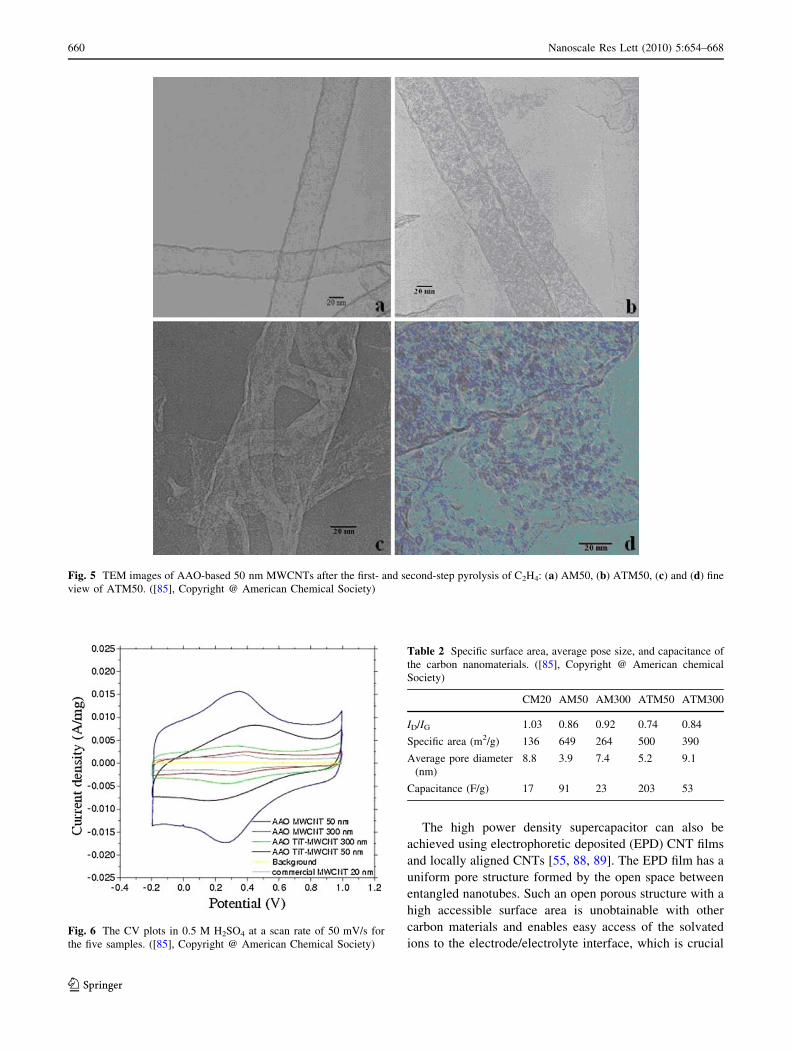
neering. Fig. 5 shows the TEM images of AAO-based
MWCNTs with a diameter of 50 nm (AM50) and AAO-
based tubes-in-tube MWCANTs (ATM50). Clearly, smal-
ler CNTs were confined with a larger one comparing
(Fig. 5d–c). Fig. 6 shows the CV plots of the samples in
the aqueous solution of 0.5 Mol/L H2SO4 at a scan rate of
50 mV/s. Two peaks on every CV plot for the five samples
indicate that supercapacitors can be realized due to the
existence of the Faradic processes. The Redox peaks on the
CV plots can be ascribed to oxygenated groups attached to
the surface of the carbon nanostructures, such as OH- [24,
25], which leads to the remarkable pseudocapacitance. The
redox reaction (faradaic process) can be considered as
following [16, 25]:
[ C � OH , C ¼ O þ Hþ þ e�
[ C ¼ O þ e� , [ C � O�:
The conductivity of CNTs can also be improved by the
OH functionalization because of the band-gap narrowing and
carrier (hole) doping [86, 87]. The better average specific
capacitance of ATM50 was attributed to its higher surface
area, better pore size distribution, and conductivity. The
amount of electrical charge accumulated due to electrostatic
attraction in EDLC depends on the area of the electrode/
electrolyte interface that can be accessed by the charge car-
riers. The higher surface area of the electrode material could
leads to higher capacitance if the area can be fully accessed
by the charge carriers. However, higher surface area does not
always result in higher capacitance, because the capacitance
depends on the pore size and its size distribution. The surface
area is hardly accessible if it consists of micropores (\2 nm)
[28]. The average pore diameters of all samples are larger
than 2 nm (Table 2). The pore size distributions for AM50
and ATM50 are narrow and show that the dominant pore
diameter is about 3.9 nm. However, the pore size distribu-
tions for other samples are broad and extend to lager size,
although the dominant pore diameter is about 2 nm for other
samples (Fig. 7). The average specific capacitance for AM50
and ATM50 is larger than those of other samples. And, the
average specific capacitance increases with the increase in
the specific surface area with the exception of ATM50. The
electrical conductivity is one of the factors that affect the
capacitance. It should be mentioned that the higher the sur-
face area, the poorer the conductivity should be. This should
be one of the reasons for the capacitance of ATM50 larger
than that of AM50 [85].
Fig. 4 SEM images of (a) the as-grown forest and (b) shape-engineered SWCNTs. ([84], Copyright @ Nature Publishing Group)
Nanoscale Res Lett (2010) 5:654–668 659
123
The high power density supercapacitor can also be
achieved using electrophoretic deposited (EPD) CNT films
and locally aligned CNTs [55, 88, 89]. The EPD film has a
uniform pore structure formed by the open space between
entangled nanotubes. Such an open porous structure with a
high accessible surface area is unobtainable with other
carbon materials and enables easy access of the solvated
ions to the electrode/electrolyte interface, which is crucial
Fig. 5 TEM images of AAO-based 50 nm MWCNTs after the first- and second-step pyrolysis of C2H4: (a) AM50, (b) ATM50, (c) and (d) fine
view of ATM50. ([85], Copyright @ American Chemical Society)
Fig. 6 The CV plots in 0.5 M H2SO4 at a scan rate of 50 mV/s for
the five samples. ([85], Copyright @ American Chemical Society)
Table 2 Specific surface area, average pose size, and capacitance of
the carbon nanomaterials. ([85], Copyright @ American chemical
Society)
CM20 AM50 AM300 ATM50 ATM300
ID/IG 1.03 0.86 0.92 0.74 0.84
Specific area (m2/g) 136 649 264 500 390
Average pore diameter
(nm)
8.8 3.9 7.4 5.2 9.1
Capacitance (F/g) 17 91 23 203 53
660 Nanoscale Res Lett (2010) 5:654–668
123

for charging the electric double layer. The current response
profiles of the CV curves at the scan rates of 50 and
1,000 mV/s (Fig. 8) are almost ideally rectangular along
the time-potential axis. The excellent CV shape reveals a
very rapid current response on voltage reversal at each end
potential, and the straight rectangular sides represent a very
small equivalent series resistance (ESR) of the electrodes
and also the fast diffusion of electrolyte in the films [1].
Fig. 9 shows the CV plots with different scan rates of the
assembled supercapacitor made of high packing and
aligned CNTs, which are close to an ideally rectangular
shape even at exceedingly high scan rates of 500 and
1,000 mV/s, indicating an extremely low ESR of the
electrodes [89]. The E–t responses of the charge process
were almost the mirror image of their corresponding dis-
charge counterparts, and no IR drop was observed, again
owing to the negligible ESR of the electrodes. The high
power density is attributed to the small internal resistance
which results from the coherent structure of the thin films
fabricated using a highly concentrated colloidal suspension
of carbon nanotubes.
Supercapacitor from CNT and Oxide Composite
A hybrid electrode consisting of CNTs and oxide incor-
porates a nanotubular backbone coated by an active phase
with pseudocapacitive properties, which fully utilize the
advantages of the pseudocapacitance and EDLC. The open
mesoporous network formed by the entanglement of
nanotubes may allow the ions to diffuse easily to the active
surface of the composite components and to lower the
equivalent series resistance (Rs) and consequently increase
the power density.
Ruthenium Oxide and CNTs Composite
Ruthenium oxide (RuO2) has been proved to be one of
important materials in oxide supercapacitors. The electro-
static charge storage as well as pseudofaradaic reactions of
RuO2 nanoparticles can be affected by the surface func-
tionality of CNTs due to the increased hydrophilicity [90].
Such hydrophilicity enables easy access of the solvated
Fig. 7 The pose size distribution calculated using BJH method. ([85],
Copyright @ American Chemical Society)
Fig. 8 (a) CVs of the nanotube
thin film supercapacitor cycled
from -1 V to ?1 V, (b) CVs of
the nanotubes thin film
supercapacitor cycled from 0 V
to ?1 V for 100 cycles, (c) CVs
of a conventional supercapacitor
made of carbon particle thin
films, and (d) charge/discharge
curves of the nanotube thin film
supercapacitor. ([55], Copyright
@ Institute of Physics)
Nanoscale Res Lett (2010) 5:654–668 661
123

ions to the electrode/electrolyte interface, which increases
faradaic reaction site number of RuO2 nanoparticles and
leads to higher capacitance. The specific capacitance of
RuO2/pristine CNT nanocomposites based on the com-
bined mass was about 70 F/g (RuO2: 13 wt% loading).
However, the specific capacitance of RuO2/hydrophilic
CNT (nitric acid treated) nanocomposites based on the
combined mass was about 120 F/g (RuO2: 13 wt% load-
ing). Kim et al. [91] reported that a three-dimensional CNT
film substrate with RuO2 showed both a very high specific
capacitance of 1,170 F/g and a high-rate capability. To
enhance its pseudocapacitance, ruthenium oxide must be
formed with a hydrated amorphous and porous structure
and a small size, because this structure provides a large
surface area and forms conduction paths for protons to
easily access even the inner part of the RuO2. The highly
dispersed RuO2 nanoparticles can be obtained on carbox-
ylated carbon nanotubes by preventing agglomeration
among RuO2 nanoparticles through bond formation
between the RuO2 and the surface carboxyl groups of the
carbon nanotubes [92] or by treating the CNTs in a con-
centrated H2SO4/HNO3 (3:1 volume ratio) mixture at
70 �C [93]. The highly dispersed RuO2 nanoparticles on
carbon nanotubes show an increased capacitance, because
the protons are able to access the inner part of RuO2 with
the decrease in size, and its utilization is increased. The
high dispersion of RuO2 is therefore a key factor to
increase the capacitance of nanocomposite electrode
materials for supercapacitors. A prominently enhanced
capacitive performance was also observed in well-dis-
persed RuO2 nanoparticles (NPs) on nitrogen-containing
carbon nanotubes [94, 95]. The function of nitrogen
amalgamation is to create preferential sites on CNTs with
lower interfacial energy for attachment of RuO2 nanopar-
ticles (Fig. 10). This crucial phenomenon leads to a
Fig. 9 Cyclic voltammograms
with different scan rates of an
assembled supercapacitor using
the nanotube thin films as
electrodes. ([89], Copyright @
Institute of Physics)
Fig. 10 Evolutionary SEM images of one single N-containing CNT
capturing RuO2 NPs under distinct coating quantity. ([94], Copyright
@ American Electrochemical Society)
662 Nanoscale Res Lett (2010) 5:654–668
123
significant improvement in the overall specific capacitance
up to the measured scan rate of 2,000 mV/s, indicating that
superior electrochemical performances for supercapacitor
applications can be achieved with RuO2–CNT-based
electrodes using nitrogen incorporation technique. How-
ever, the commercialization of RuO2/CNTs composite is
very difficult because of the high cost and high toxicity of
RuO2.
Co3O4 and CNTs composite
Co3O4 is also an important transition-metal oxide and has
great application in heterogeneous catalysts, anode mate-
rials in Li-ion rechargeable batteries, solid-state sensors,
solar energy absorbers, ceramic pigments, and electro-
chromic devices [96]. Shan et al. [97] reported a novel type
of multi-walled carbon nanotubes (MWCNTs)/Co3O4
composite electrode for supercapacitors. The electrode was
prepared through a facile and effective method, which
combined the acid treatment of MWCNTs and in situ
decomposition of Co(NO3)2 in n-hexanol solution at
140 �C. The MWCNTs/Co3O4 composites show high
capacitor property, and their best specific capacitance is up
to 200 F/g, which is significantly greater than that of pure
MWCNTs (90 F/g).
Manganese Oxide and CNTs Composite
Manganese oxide is one of the most promising pseudoca-
pacitor electrode materials with respect to both its specific
capacitance and cost effectiveness. CNT is effective for
increasing the capacitance and improving the electro-
chemical properties of the a-MnO2�nH2O electrodes and a
very promising material as a conductive additive for
capacitor or battery electrodes [98]. The performance of
real capacitors based on manganese oxide is limited by the
two irreversible reactions Mn(IV)–Mn(II) and Mn(IV)–
Mn(VII), which potentially depend on the electrolyte pH.
In particular, with real capacitors, the electrolyte usually
leads to the dissolution of the negative electrode. The
CNTs can help in preserving the electrodes integrity during
cycling. The long cycle performance at a high charge–
discharge current of 2 A/g for the a-MnO2/SWCNTs
composites was obtained [99]. All the composites with
different SWCNT loads showed excellent cycling capa-
bility, even at the high current of 2 A/g, with the MnO2 and
20 wt% SWCNT composite showing the best combination
of efficiency of 75% and specific capacitance of 110 F/g
after 750 cycles. The initial specific capacitance of the
MnO2/CNTs nanocomposite (CNTs coated with uniform
birnessite-type MnO2) in an organic electrolyte at a large
current density of 1 A/g was 250 F/g, indicating excellent
electrochemical utilization of the MnO2 because the
addition of CNTs as a conducting agent improved the high-
rate capability of the nanocomposite considerably [100].
An in situ coating technique was used to prepare the MnO2/
MWCNT composite, where the nanosized e-MnO2 uniform
layer (6.2 nm in thickness) covered the surface of the
MWCNT and the original structure of the pristine
MWCNT was retained during the coating process. The
specific capacitance of the composite electrode reached
250.5 F/g, which was significantly higher than that of a
pure MWCNT electrode [101].
Ni(OH)2 and CNT composite
Ni(OH)2 is often used in the hybrid supercapacitor with
carbon (using KOH solution as electrolyte). The positive
electrode materials (Ni(OH)2) converts to NiOOH with the
formation of proton and electron during the charge process.
The rate capability of Ni(OH)2 is associated with the pro-
ton diffusion in Ni(OH)2 framework. The Ni(OH)2/CNTs
composite provided a shorter diffusion path for proton
diffusion and larger reaction surface areas, as well as
reduces the electrode resistance due to the high electronic
conductivity of CNTs [102]. Wang et al. [102] reported
that the CNTs can reduce the aggregation of Ni(OH)2
nanoparticles, inducing a good distribution of the nano-
sized Ni(OH)2 particles on the cross-linked, netlike struc-
ture CNTs. The rate capability and utilization of Ni(OH)2
were greatly improved, and the composite electrode resis-
tance was reduced. A specific energy density of 32 Wh/kg
at a specific power density of 1,500 W/kg was obtained in
the hybrid supercapacitor. The capacitance can be further
improved by heating the Ni(OH)2/CNTs composite at
300 �C because of the formation of an extremely NiOx thin
layer on CNT film [103]. The specific capacitance
decreased with the increase in NiOx in the composite if the
NiOx percentage was above 8.9 wt%. A specific capaci-
tance of 1,701 F/g was reported for 8.9 wt% NiOx/CNT
electrode.
Other Oxides and CNTs Composites
The Ni–Co oxides/CNT composite electrode, prepared by
adding and thermally decomposing nickel and cobalt
nitrates directly onto the surface of carbon nanotube/
graphite electrode, has excellent charge–discharge cycle
stability (0.2% loss of the specific capacitance at the
1,000th charge–discharge cycles) and good charge–dis-
charge properties at high current density [104]. The specific
capacitance of the composite increases significantly with
a decrease in Ni/Co molar ratio when cobalt content is
below 50% (in molar ratio) and then decreases rapidly
when cobalt content is in the range between 50 and 100%.
Nanoscale Res Lett (2010) 5:654–668 663
123
A maximum value of the specific capacitance (569 F/g) was
obtained at Ni/Co molar ratio = 1:1. Also, the specific
capacitance of the nickel–cobalt oxides/CNT (Ni/Co =
1:1) electrode is much larger than the simple sum of the
specific capacitances of the nickel oxide/CNT and cobalt
oxide/CNT electrodes. Su et al. [105] reported a self-hybrid
composite electrode composing of MWCNT and Co–Al-
layered double hydroxides. The CV curves approached
rectangle shapes, and the charge and discharge curves were
basically symmetrical. Compared to MWCNTs superca-
pacitor, this new supercapacitor has good long-term sta-
bility, larger maximum power (6,400 W/kg) and energy
density (13.2 Wh/kg), and a higher specific capacitance
of 15.2 F/g even after 1,000 cycles at a large current of
2 A/g.
The capacitance of V2O5/CNTs composite is also larger
than those of pure V2O5 and CNTs [106]. The addition
of SnO2 to the V2O5/CNTs can further increase the capaci-
tance, because SnO2 can improve the electronic proper-
ties of V2O5. The LiNi0.8Co0.2O2/MWCNT (5–15 nm in
diameter) composite capacitor has a specific capacitance
and energy density of 270 F/g and 317 Wh/kg, respectively
[107]. The MWCNTs substantially improves the electro-
chemical performance of the LiNi0.8Co0.2O2-based capac-
itor because of the combination of increased conductivity,
proper pore distributions, good mechanical properties, and
electrolyte accessibility. A chromium oxide/SWCNT-based
electrodes shows exceptionally quick charge propagation
due to the overall physical and textural properties of
SWCNT [60]. Nanosized chromium oxide particles finely
dispersed at nanoscale in the SWCNT make possible the
enhanced charging rate of the electrical double layer and
allow fast faradaic reactions. Chromium-containing species
present as CrO3 inside SWCNTs as well as in the form of
CrO2Cl2 (possibly along with CrO3 too) between SWCNTs
within bundles supply redox reactions due to access by the
electrolyte in spite of its encapsulated (and intercalated)
location because of the numerous side openings created all
along the SWCNT defective walls during the filling step.
Reddy et al. [108] compared the electrochemical prop-
erties of RuO2/MWCNT, TiO2/MWCNT, and SnO2/
MWCNT nanocrystalline composites for supercapacitor
electrodes. The average specific capacitances measured
using the three electrochemical techniques of the pure
MWCNT, RuO2/MWCNT, TiO2/MWCNT, and SnO2/
MWCNT nanocomposite electrodes are 67, 138, 160, and
93 F/g, respectively. The enhancement of the specific
capacitance of metal oxide dispersed MWCNT from pure
MWCNT is due to the progressive redox reactions occur-
ring at the surface and bulk of transition metal oxides
through faradaic charge transfer due to the modification of
the surface morphology of MWCNT by the nanocrystalline
RuO2, TiO2, and SnO2.
Supercapacitor from CNT and Polymer Composite
Electronically conducting polymers are promising sup-
ercapacitor materials for two main reasons: (1) high spe-
cific capacitance because the charge process involves the
entire mass and (2) high conductivity in charged state,
leading to low ESR and high power density. The main
drawback using polymer in supercapacitor is the cycling
stability because of typical shrinkage, breaking, and cracks
appearing in subsequent cycles. It has been already proved
that composites based on CNTs and conducting polymers,
such as polypyrrole and polyaniline, are very interesting
electrode materials, because the entangled mesoporous
network of nanotubes in the composite can adapt to the
volume change. That allows the shrinkage to be avoided,
and hence a more stable capacitance with cycling to be
obtained.
Polymer and CNTs Hybrid Composite
Lota et al. [3] reported a novel composite material prepared
from a homogenous mixture of polymer poly(3,4-ethyl-
enedioxythiophene; PEDOT) and CNTs or by chemical or
electrochemical polymerization of EDOT directly on
CNTs. The optimal proportions of the composite are
20–30% of CNTs and 70–80% of PEDOT. Among the
three methods used for the composites preparation, the
electrochemical method gave the best capacitance results
(150 F/g). And such material had a good cycling perfor-
mance with a high stability in all the electrolytes. Another
quite important advantage of this composite is its signifi-
cant volumetric energy because of the high density of
PEDOT. Due to the open mesoporous network of nano-
tubes, the easily accessible electrode/electrolyte interface
allows quick charge propagation in the composite material
and an efficient reversible storage of energy in PEDOT
during subsequent charging/discharging cycles.
The capacitance values for the composites [20 wt% of
CNTs and 80 wt% of conducting polymers (ECP), such as
polyaniline (PANI) and polypyrrole (PPy)] strongly depend
on the cell construction [109]. In the case of three electrode
cells, extremely high values could be found from 250 to
1100 F/g; however, in the two-electrode cell, much smaller
specific capacitance values of 190 F/g for PPy/CNTs and
360 F/g for PANI/CNTs had been measured. It highlights
the fact that only two-electrode cells allow a good esti-
mation of materials performance in electrochemical
capacitors. The CNTs/PPy film shows excellent charge
storage and transfer capabilities, attributed to the high
surface area, conductivity, and electrolyte accessibility of
the nanoporous structure [64]. The aligned CNTs/PPy
composite film had an exciting combination of exceptional
charge storage capacities as large as 2.25 F/cm2 and
664 Nanoscale Res Lett (2010) 5:654–668
123
improved device response times relative to pure PPy films.
The superior performance of the composite relative to their
component materials is attributed to the combination of
electrolyte accessibility, reduced diffusion distances, and
improved conductivity in the redox-pseudocapacitive
composite structure. An et al. [110] demonstrated that the
SWCNT/PPy (1/1 in weight) nanocomposite electrode
shows much higher specific capacitance than pure PPy and
as-grown SWCNT electrodes, due to the uniformly coated
PPy on the SWNTs. A maximum specific capacitance of
265 F/g from the SWNTs/PPy nanocomposite electrode
containing 15 wt% of the conducting agent was obtained.
The addition of conducting agent into the SWCNT-PPy
nanocomposite electrode gives rise to an increase in the
specific capacitance by reducing the internal resistance of
the supercapacitor.
The specific capacitance of PANI/SWCNT composite
electrode increased as the amount of the deposited PANI
onto SWCNTs increases up to 73 wt%, where the PANI
was wrapped around SWCNT [111]. Beyond 73 wt%, the
additional PANI was deposited either in the mesopores
between SWCNTs or in the form of film over the surface,
which caused drop in the capacitance. The trend of the
capacitance as a function of the PANI weight was opposite
to that of specific resistivity. The highest specific capaci-
tance, specific power, and specific energy values of 485
F/g, 228Wh/kg and 2,250 W/kg were observed for 73 wt%
PANI deposited onto SWCNTs. And the PANI/SWCNT
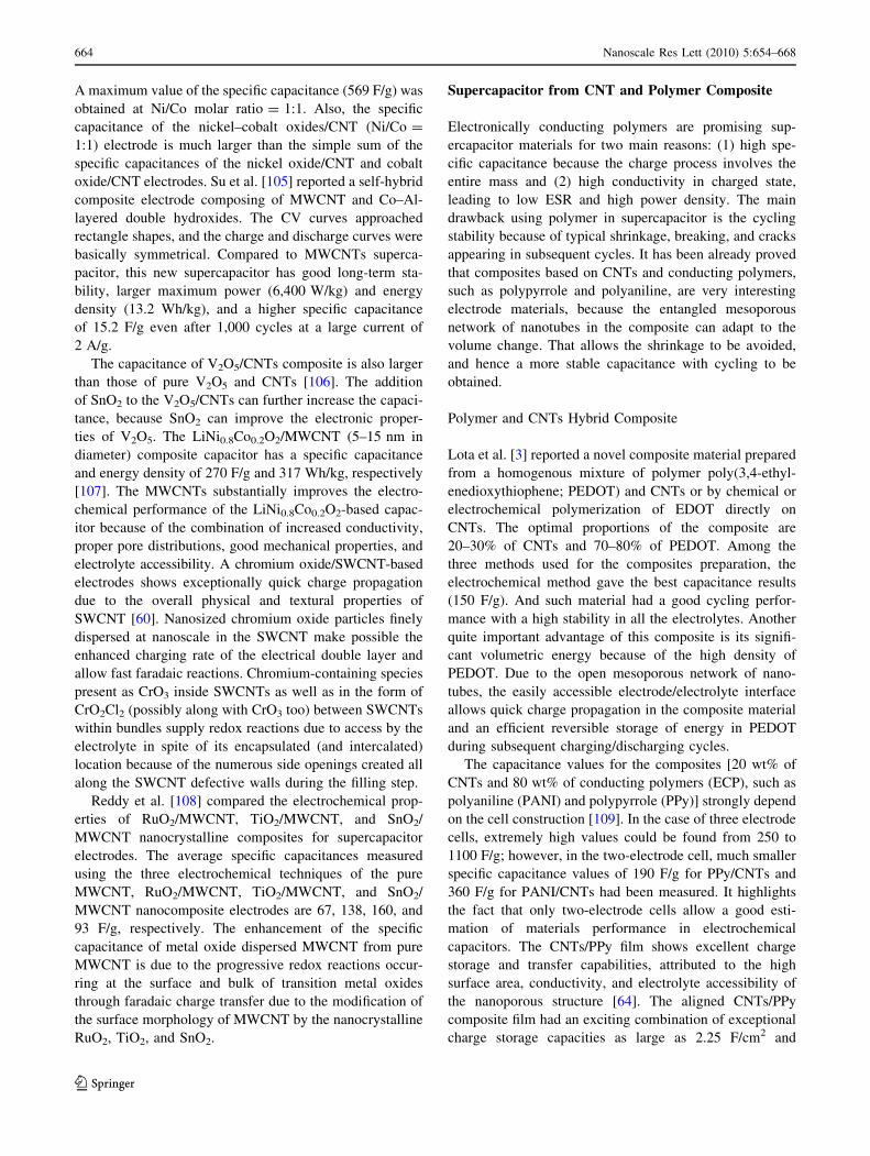
composites showed long cyclic stability. Figure 11 shows
the specific capacitance of PANI/SWCNT composite films
electrodes as a function of discharge current density [112].
The SWCNT/PANI composite film shows a higher specific
capacitance, because the presence of SWCNT in the
growth solution could promote the rate of aniline poly-
merization and result in a smooth, uniform, and highly
porous composite film with a higher doping degree and
lower defect density compared to the rough spherical grain-
based pure PANI film. A MWCNT/PANI composite syn-
thesized by an in situ chemical oxidative polymerization
method showed much higher specific capacitance (328 F/g)
because MWCNT made the composites had more active
sites for faradiac reaction [113]. Similarly, the highest
specific capacitance value of 224 F/g was obtained for the
MWCNT/PANI composite materials containing MWCNTs
of 0.8 wt% [114]. The same composite (MWCNT/PANI)
synthesized by microwave-assisted polymerization was a
core–shell structure with PANI layers (50–70 nm), which
has an enhanced specific capacitance of 322 F/g with a
specific energy density of 22 W h/kg [115].
The CNTs/PAN composite with a ratio of 30/70
between CNT and PAN pyrolysized from a CNT/PAN
blends for 180 min gave a high capacitance (100 F/g)
although its specific surface area (157 m2/g) is not the
highest compared with the 50/50 CNT/PAN composite
(233 m2/g, 57 F/g) [116]. This suggested that the content of
PAN must be high enough not only to favor a large gas
evolution, which develops porosity, but also to obtain the
highest amount of residual nitrogen in the negative and
positive ranges of potential, respectively, which contrib-
uted more to the pseudofaradiac charge transfer reactions.
Polymer and CNTs Ternary Composites
Single wall carbon nanotubes in the ternary composite,
PAN/SAN/SWCNTs, acted as a compatabilizer for poly-
acrylonitrile (PAN)/styreneeacrylonitrile (SAN) copolymer
blends, which was used to develop porosity control in the
carbonized PAN/SAN/SWCNT composites with an aver-
age pore size in the range of 3–13 nm [117]. Extremely
high electrical double-layer capacity in the range of 83–205
mF/cm2 was observed in the ternary composites.
DNA and CNTs Composite
DNA is a good candidate for improved electrical conduc-
tivity for electrochemical devices with CNTs, because
DNA has electrical characteristics similar to those of
semiconducting diodes. In addition, DNA can more
effectively coat, separate, and solubilize CNTs than other
surfactants because of the large surface area of its phos-
phate backbone, which interacts with water, and there are
many bases in DNA that can bind to CNTs. Therefore,
DNA wrapping can debundle CNTs in high concentration
Fig. 11 Specific capacitances of the SWNT/PANI composite film
prepared from the growth solutions with (a) 0, (b) 4, and (c) 8 wt%
SWCNT as a function of current density. ([112], Copyright @
American Electrochemical Society)
Nanoscale Res Lett (2010) 5:654–668 665
123
CNT dispersions. Recently, Shin et al. [118] reported the
DNA-wrapped SWCNT hydrid fibers for supercapacitor
electrode materials. The DNA–SWNT hybrid fibers were
obtained using the wet-spinning method reported previ-
ously. The capacitance of the DNA-wrapped SWCNT
fibers was 60 F/g (in a phosphate buffered saline solution),
larger than that of pure SWCNT mat (30 F/g) due to the
improved electrical conductivity, high CNT surface area
and enhanced mechanical stability due to the p–p inter-
action between the DNA and the CNT sidewall.
Summary
Supercapacitor, as an energy storage device, have been
studied and used in many fields. The electrode material of
the supercapacitor needs to satisfy three basic require-
ments: (1) high capacitance, (2) low resistance, and (3)
stability. CNT-based electrode materials, including CNTs,
CNT/oxide composite, and CNT/polymer composite, have
been widely studied in past decade and attracting increas-
ing attentions for their application to supercapacitor due to
their satisfaction to the criteria.
As the electric-double-layer capacitor, the performance
of the CNT-based supercapacitor is closely related to the
physical properties of the CNTs, such as specific surface
area. The performance should depend on the synthesis and
post-treatment methods of the CNTs. It is clear that the
specific surface area is not the solely dominant factor to the
performance. The capacitance of the CNTs is affected by
various factors, including specific surface area, pore size,
pore size distribution, conductivity, etc. Only by optimiz-
ing these factors can the performance be improved. Various
methods have been proposed for the purpose, such as
functionalization, oxidization, and doping, which can lead
to high capacitance through the improvement in conduc-
tivity, fast ion diffusivity, and addition of pseudocapaci-
tance. Other methods were introduced to modify the
structure of the CNTs, such as densely packed and ordered
CNTs and tubes-in-tube CNTs, which result in the
improvement in the capacitance and conductivity without
introducing any functional groups. High stability should be
achieved by these modifications. Although the capacitance
of the pure CNTs was enhanced and its stability was
improved, the capacitance of CNT-based supercapacitor is
still lower than that of amorphous carbon or porous carbon
and can be enhanced by optimizing the surface area, pore
size, and pore size distribution.
High capacitance can also be achieved by using the
mixture of the CNTs with oxide, polymer, or both as the
electrode. The hybrid supercapacitor requires that the oxide
nanoparticles should be chemically attached to the walls of
CNTs or the CNTs should be uniformly covered by the
polymer with accurately controlled thickness. And the ratio
between the oxide/polymer and CNTs is critical to the
enhancement of the capacitance. Presently, there has no
general answer to the ratio in literatures because the
starting materials, CNTs, oxide, and polymer, and pro-
cessing methods are different from literature to literature.
The systematical investigations are needed to solve this
problem. However, the stability of the hybrid supercapac-
itor is still questionable.
Open Access This article is distributed under the terms of the
Creative Commons Attribution Noncommercial License which per-
mits any noncommercial use, distribution, and reproduction in any
medium, provided the original author(s) and source are credited.
References
1. B.E. Conway, Electrochemical Supercapacitors: ScientificFundamentals And Technological Applications (Kluwer Aca-
demic/Plenum, New York, 1999)
2. Website: http://en.wikipedia.org/wiki/Supercapacitor
3. K. Lota, V. Khomenko, E.J. Frackowiak, J. Phys. Chem. Solids
65, 295 (2004)
4. S.K. Ryu, X. Wu, Y.G. Lee, S.H. Chang, J. Appl. Polym. Sci.
89, 1300 (2003)
5. S. Patra, N. Munichandraiah, J. Appl. Polymer Sci. 106, 1160
(2007)
6. F. Marchioni, J. Yang, W. Walker, F. Wudl, J. Phys. Chem.
B 110, 22202 (2006)
7. K.S. Ryu, Y.G. Lee, Y.S. Hong, Y.J. Park, X.L. Wu, K.M. Kim,
M.G. Kang, N.G. Park, S.H. Chang, Electrochim. Acta 50, 843
(2004)
8. M.D. Ingram, H. Staesche, K.S. Ryder, Solid State Ionics 169,
51 (2004)
9. K.R. Prasad, N. Munichandraiah, Electrochem. Solid State Lett.
5, A271 (2002)
10. J.Y. Kim, I.J. Chung, J. Electrochem. Soc. 140, A1376 (2002)
11. K.S. Ryu, K.M. Kim, N.G. Park, Y.J. Park, S.H. Chang, J. Power
Sources 103, 305 (2002)
12. J.C. Lassegues, J. Grondin, T. Becker, L. Servant, M. Hernan-
dez, Solid State Ionics 77, 311 (1995)
13. K.H. Chang, C.C. Hu, Electrochem. Solid State Lett. 7, A466
(2004)
14. D. Rochefort, D. Guay, Alloys Compd. 400, 257 (2005)
15. J.N. Broughton, M.J. Brett, Electrochim. Acta 49, 4439 (2005)
16. P. Ragupathy, H.N. Vasan, N. Munichandraiah, J. Power
Sources 155, A34 (2008)
17. K. Macounova, I. Jirka, A. Trojanek, M. Makarova, Z. Samec,
P. Krtil, J. Electrochem. Soc. 154, A1077 (2007)
18. M.W. Xu, D.D. Zhao, S.J. Bao, H.L. Li, J. Solid State Elect-
rochem. 11, 1101 (2007)
19. T.P. Gujar, V.R. Shinde, C.D. Lokhande, W.Y. Kim, K.D. Jung,
O.S. Joo, Electrochem. Communica. 9, 504 (2007)
20. S.L. Kuo, J.F. Lee, N.L. Wu, J. Electrochem. Soc. 154, A34
(2007)
21. K. Yokoshima, T. Shibutani, M. Hirota, W. Sugimoto, Y.
Murakami, Y. Takasu, J. Power Sources 160, 1480 (2006)
22. A. Jayalakshmi, N. Venugopal, K.P. Raja, M.M. Rao, J. Power
Sources 158, 1538 (2006)
23. S.H. Lee, C.E. Tracy, J.R. Pitts, Electrochem. Solid State Lett. 7,
A299 (2004)
666 Nanoscale Res Lett (2010) 5:654–668
123
24. Y.B. Mo, M.R. Antonio, D.A. Scherson, J. Phys. Chem. B 104,
9777 (2000)
25. J.M. Miller, B. Dunn, T.D. Tran, R.W. Pekala, J. Electrochem.
Soc. 144, L309 (1997)
26. B.E. Conway, J. Electrochem. Soc. 138, 1539 (1991)
27. J.H. Jiang, A. Kucernak, Electrochim. Acta 47, 2381 (2002)
28. L.M. Huang, H.Z. Lin, T.C. Wen, A. Gopalan, Electrochim.
Acta 52, 1058 (2006)
29. J.W. Long, K.E. Swider, C.I. Merzbacher, D.R. Rolison,
Langmuir 15, 780 (1999)
30. H.I. Becker, Low voltage electrolytic capacitor, US patent
2800616
31. E. Frackowiak, F. Beguin, Carbon 39, 937 (2001)
32. E. Frackowiak, Phys. Chem. Chem. Phys. 9, 1774 (2007)
33. J. Chmiola, G. Yushin, Y. Gogotsi, C. Portet, P. Simon, P.L.
Taberna, Science 313, 1760 (2006)
34. E. Raymundo-Pinero, F. Leroux, F. Beguin, Adv. Mater. 18,
1877 (2006)
35. A.B. Fuertes, G. Lota, T.A. Centeno, E. Frackowiak, Electro-
chim. Acta 50, 2799 (2005)
36. D. Hulicova, J. Yamashita, Y. Soneda, H. Hatori, M. Kodama,
Chem. Mater. 17, 1241 (2005)
37. K. Leitner, A. Lerf, M. Winter, J.O. Besenhard, S. Villar-Rodil,
F. Suarez-Garci, A. Martinez-Alonso, J.M.D. Tascon, J. Power
Sources 153, 419 (2000)
38. P.J. Mahon, G.L. Paul, S.M. Keshishian, A.M. Vassallo, J.
Power Sources 91, 68 (2000)
39. N.L. Wu, S.Y. Wang, J. Power Sources 110, 233 (2002)
40. C. Portet, P.L. Taberna, P. Simon, C. Laberty-Robert, Electro-
chim. Acta 49, 205 (2004)
41. C. Kim, K.S. Yang, Appl. Phys. Lett. 83, 1216 (2003)
42. C. Vix-Guterl, S. Saadallah, K. Jurewicz, E. Frackowiak, M.
Reda, J. Parmentier, J. Patarin, F. Beguin, Mater. Sci. Engineer.
B 108, 148 (2004)
43. D. Kalpana, K.S. Omkumar, S.S. Kumar, N.G. Renganathan,
Electrochim. Acta 52, 2309 (2006)
44. M. Min, K. Machida, J.H. Jang, K. Naoi, J. Electrochem. Soc.
153, A334 (2006)
45. C. Arbizzani, M. Mastragostino, L. Meneghello, R. Paraventi,
Adv. Mater. 8, 331 (1996)
46. J.M. Miller, B. Dunn, Langmuir 15, 799 (1999)
47. S. Iijima, Nature 354, 56 (1991)
48. M.S. Dresselhaus, G. Dresselhaus, P.C. Eklund, Science ofFullerenes and Carbon Nanotubes (Academic, New York/San
Diego, 1996)
49. R. Saito, G. Dresselhaus, M.S. Dresselhaus, J. Appl. Phys. 73,
494 (1993)
50. M.S. Dresselhaus, G. Dresselhaus, R. Saito, Solid State Com-
mun. 84, 201 (1992)
51. J.P. Issi, L. Langer, J. Heremans, C.H. Olk, Carbon 33, 941
(1995)
52. T.W. Ebbesen, H.J. Lezec, H. Hiura, J.W. Bennett, H.F. Gha-
emi, T. Thio, Nature 382, 54 (1996)
53. C. Niu, E.K. Sichel, R. Hoch, D. Moy, H. Tennent, Appl. Phys.
Lett. 70, 1480 (1997)
54. K.H. An, W.S. Kim, Y.S. Park, Y.C. Choi, S.M. Lee, D.C.
Chung, D.J. Bae, S.C. Lim, Adv. Mater. 13, 497 (2001)
55. C.S. Du, N. Pan, Nanotechnol. 17, 5314 (2006)
56. E. Frackowiak, K. Metenier, V. Bertagna, F. Beguin, Appl.
Phys. Lett. 77, 2421 (2000)
57. A.L.M. Reddy, F.E. Amitha, I. Jafri, S. Ramaprabhu, Nanoscale
Res. Letts. 3, 145 (2008)
58. C.G. Liu, M. Liu, F. Li, H.M. Cheng, Appl. Phys. Let. 92,
143108 (2008)
59. J.N. Barisci, G.G. Wallace, D. Chattopadhyay, F. Papadimit-
rakopoulos, R.H. Baughman, J. Electrochem. Soc. 150, E409
(2003)
60. L.H. Su, X.G. Zhang, C.Z. Yuan, B. Gao, J. Electrochem. Soc.
155, A110 (2008)
61. C.Y. Lee, H.M. Tsai, H.J. Chuang, S.Y. Li, P. Lin, T.Y. Tseng,
J. Electrochem. Soc. 152, A716 (2005)
62. G. Arabale, D. Wagh, M. Kulkarni, I.S. Mulla, S.P. Vernekar, K.
Vijayamohanan, A.M. Rao, Chem. Phys. Lett. 376, 207 (2003)
63. K. Liang, K. An, Y. Lee, J. Mater. Sci. Eng. 21, 292 (2005)
64. M. Hughes, G.Z. Chen, M.S.P. Shaffer, D.J. Fray, A.H. Windle,
Chem. Mater. 14, 1610 (2002)
65. J.N. Barisci, G.G. Wallace, R.H. Baughman, J. Electrochem.
Soc. 147, 4580 (2000)
66. S. Shiraishi, H. Kurihara, K. Okabe, D. Hulicova, A. Oya,
Electrochem. Commun. 4, 593 (2002)
67. H. Zhang, G.P. Cao, Y.S. Yang, Nanotechnol. 18, 195607
(2007)
68. H. Zhang, G.P. Cao, Y.S. Yang, Z.N. Gu, J. Electrochem. Soc.
155, K19 (2008)
69. H.J. Ahn, J.I. Sohn, Y.S. Kim, H.S. Shim, W.B. Kim, T.Y.
Seong, Electrochem. Commun. 8, 513 (2006)
70. M. Jung, H.G. Kim, K. Lee, O.S. Joo, S.I. Mho, Electrochim.
Acta 50, 857 (2004)
71. G. Che, B.B. Lakshmi, E.R. Fisher, C.R. Martin, Nature 393,
346 (1998)
72. H. Pan, J.Y. Lin, Y.P. Feng, H. Gao, IEEE Trans. Nanotechnol.
3, 462 (2004)
73. H. Pan, H. Gao, S.H. Lim, Y.P. Feng, J. Lin, J. Nanosci.
Nanotech. 4, 1014 (2004)
74. E. Frackowiak, K. Jurewicz, S. Delpeux, F. Beguin, J. Power
Sources 822, 97–98 (2001)
75. C. Li, D. Wang, T. Liang, X. Wang, J. Wu, X. Hu, J. Liang,
Powder Technol. 142, 175 (2004)
76. K.H. An, W.S. Kim, Y.S. Park, J.M. Moon, D.J. Bae, S.C. Lim,
Y.S. Lee, Y.H. Lee, Adv. Funct. Mater. 11, 387 (2001)
77. E. Frackowiak, S. Delpeux, K. Jurewicz, K. Szostak, D. Cazorla-
Amoros, F. Beguin, Chem. Phys. Lett. 261, 35 (2002)
78. C.G. Liu, H.T. Fang, F. Li, M. Liu, H.M. Cheng, J. Power
Sources 160, 758 (2006)
79. Y.T. Kim, Y. Ito, K. Tadai, T. Mitani, U.S. Kim, H.S. Kim,
B.W. Cho, Appl. Phys. Lett. 87, 234106 (2005)
80. J.Y. Lee, K.H. An, J.K. Heo, Y.H. Lee, J. Phys. Chem. B 107,
8812 (2003)
81. H. Pan, Y.P. Feng, J. Lin, J. Phys, Conden. Matter 18, 5175
(2006)
82. C. Zhou, S. Kumar, C.D. Doyle, J.M. Tour, Chem. Mater. 17,
1997 (2005)
83. B.J. Yoon, S.H. Jeong, K.H. Lee, H.S. Kim, C.G. Park, J.H. Han,
Chem. Phys. Lett. 380, 170 (2004)
84. D.N. Futaba, K. Hata, T. Yamada, T. Hiraoka, Y. Hayamizu, Y.
Kakudate, O. Tanaike, H. Hatori, M. Yumura, S. Iijima, Nature
Mater. 5, 987 (2006)
85. H. Pan, C.K. Poh, Y.P. Feng, J. Lin, Chem. Mater. 19, 6120
(2007)
86. H. Pan, Y.P. Feng, J. Lin, Phys. Rev. B 70, 245425 (2004)
87. H. Pan, Y.P. Feng, J. Lin, J. Comput. Theor. Nanosci. 5, 2233
(2008)
88. C.S. Du, N. Pan, J. Power Sources 160, 1487 (2006)
89. C.S. Du, J. Yeh, N. Pan, Nanotechnol. 16, 350 (2005)
90. J.H. Park, J.M. Ko, O.O. Parka, J. Electrochem. Soc. 150, A864
(2003)
91. H. Kim, J.H. Kim, K.B. Kim, Electrochem. Solid-State Lett. 8,
A369 (2005)
Nanoscale Res Lett (2010) 5:654–668 667
123
92. Y.T. Kim, K. Tadai, T. Mitani, J. Mater. Chem. 15, 4914 (2005)
93. Y.T. Kim, T. Mitani, Appl. Phys. Lett. 89, 033107 (2006)
94. W.C. Fang, M.S. Leu, K.H. Chen, L.C. Chen, J. Electrochem.
Soc. 155, K15 (2008)
95. W.C. Fang, K.H. Chen, L.C. Chen, Nanotechnol. 18, 485716
(2007)
96. K. Ramachandram, C.O. Oriakhi, M.M. Lerner, V.R. Koch,
Mater. Res. Bull. 31, 767 (1996)
97. Y. Shan, L. Gao, Mater. Chem. Phys. 103, 206 (2007)
98. E. Raymundo-Pinero, V. Khomenko, E. Frackowiak, F. Beguin,
J. Electrochem. Soc. 152, A229 (2005)
99. V. Subramanian, H. Zhu, B. Wei, Electrochem. Commun. 8, 827
(2006)
100. S.B. Ma, K.W. Nam, W.S. Yoon, X.Q. Yang, K.Y. Ahn, K.H.
Oh, K.B. Kim, J. Power Sources 178, 483 (2008)
101. X. Xie, L. Gao, Carbon 45, 2365 (2007)
102. Y.G. Wang, L. Yu, Y.Y. Xia, J. Electrochem. Soc. 153, A743
(2006)
103. K. Nam, K. Kim, E. Lee, W. Yoon, X. Yang, K. Kim, J. Power
Sources 182, 642 (2008)
104. Z. Fan, J. Chen, K. Cui, F. Sun, Y. Xu, Y. Kuang, Electrochim.
Acta 52, 2959 (2007)
105. M. Jayalakshm, M.M. Raoa, N. Venugopal, K.B. Kim, J. Power
Sources 166, 578 (2007)
106. G. Wang, M. Qu, Z. Yu, R. Yuan, Mater. Chem. Phys. 105, 169
(2007)
107. G. Lota, E. Elzbieta Frackowiak, J. Mittal, M. Monthioux,
Chem. Phys. Lett. 434, 73 (2007)
108. A.L.M. Reddy, S. Ramaprabhu, J. Phys. Chem. C Nanomater.
Interfaces 111, 7727 (2007)
109. V. Khomenko, E. Frackowiak, F. Beguin, Electrochim. Acta 50,
2499 (2005)
110. K.H. An, K.K. Jeon, J.K. Heo, S.C. Lim, D.J. Bae, Y.H. Lee,
J. Electrochem. Soc. 149, A1058 (2002)
111. V. Gupta, N. Miura, Electrochim. Acta 52, 1721 (2006)
112. Y.K. Zhou, B.L. He, W.J. Zhou, H.L. Li, J. Electrochem. Soc.
151, A1052 (2004)
113. B. Dong, B.L. He, C.L. Xu, H.L. Li, Mater. Sci. Eng. B 143,
7 (2007)
114. L.B. Kong, J. Zhang, J.J. An, Y.C. Luo, L. Kang, J. Mater. Sci.
43, 3664 (2008)
115. H. Mi, X. Zhang, S. An, X. Ye, S. Yang, Electrochem. Commun.
9, 2859 (2007)
116. F. Beguin, K. Szostak, G. Lota, E. Frackowiak, Adv. Mater.
7, 2380 (2005)
117. C. Zhou, T. Liu, T. Wang, S. Kumar, Electrochim. Acta 52,
1721 (2006)
118. S.R. Shin, C.K. Lee, I. So, J.H. Jeon, T.M. Kang, C. Kee, S.I.
Kim, G.M. Spinks, G.G. Wallace, S.J. Kim, Adv. Mater. 20, 466
(2008)
668 Nanoscale Res Lett (2010) 5:654–668
123