Carbon Nanotube Appliques for Fatigue Crack · PDF fileSelective electrodes integrated to...
20
205 Portland St • Boston, MA 02114 • 617.447.2172 • http://www.metisdesign.com Seth S. Kessler, Ph.D. President/CEO Metis Design Corporation 1 September 2015 structural health monitoring multi-functional materials lean enterprise solutions Carbon Nanotube Appliques for Fatigue Crack Diagnostics
Transcript of Carbon Nanotube Appliques for Fatigue Crack · PDF fileSelective electrodes integrated to...

205 Portland St • Boston, MA 02114 • 617.447.2172 • http://www.metisdesign.com
Seth S. Kessler, Ph.D. President/CEO
Metis Design Corporation 1 September 2015
structural health monitoringmulti-functional materialslean enterprise solutions
Carbon Nanotube Appliques for Fatigue Crack Diagnostics

IWSHM 2015 2 of 20
• Conformal assemblies for composite & metallic host structures Central carbon nanotube (CNT) layer is core to these properties
Surrounded by electrically insulating layers (film adhesive and/or GFRP)
Selective electrodes integrated to steer current flow
• No impact to physical structure, 100 - 200 µm & 5 - 10 g/m2
Can be co-cured with composite laminate
Can be installed over composite or metallic skin in secondary process
• Enable multi-functional capabilities: conducting, heating, sensing
Conformal Multi-functional Assemblies
© 2015 Metis Design Corporation

IWSHM 2015 3 of 20
• SHM improves reliability, safety & readiness @ reduced costs sensors add weight, power consumption & computational bandwidth
cables add weight, complexity, as well as durability & EMI concerns
scaling SHM for large-area coverage has presented challenges
• Advantages of proposed CNT-based SHM methodology sensing elements actually improve specific strength/stiffness of structure
conformal electrodes lighter & more durable than cable
simple to scale over large structure, maintains good local resolution
CNT Structural Health Monitoring
© 2015 Metis Design Corporation
Traditional SHM CNT-based SHM

IWSHM 2015 4 of 20
• Simple notch-cut experiment presented at prior IWSHM in 2011 2400 mm² CNT w/160 mm² damage yields ~25% in resistance increase
same damage in 1 m long strip of same width would yield ~2% change
10 mm² damage would still be over noise floor
• 2D network resistor model in good agreement with data
Sparse Electrode Notch-Cutting Tests (N111-067)
© 2015 Metis Design Corporation

IWSHM 2015 5 of 20
• Simple 4-pt bend experiment also presented at IWSHM 2011 Resistance is proportional to strain for low displacement
tensile-side resistance increases due to CNT network being stretched-out
compressive-side resistance decreases due to CNT being pushed together
• Permanent resistance increase after 25 mm deflection (>400 N)
4-Point Bent Results Under Load (N111-067)
© 2015 Metis Design Corporation
Loaded measurements
Unloaded measurements

IWSHM 2015 6 of 20
• To use CNT as sensors in service, need to evaluate durability Environmental effects
Mechanical effects
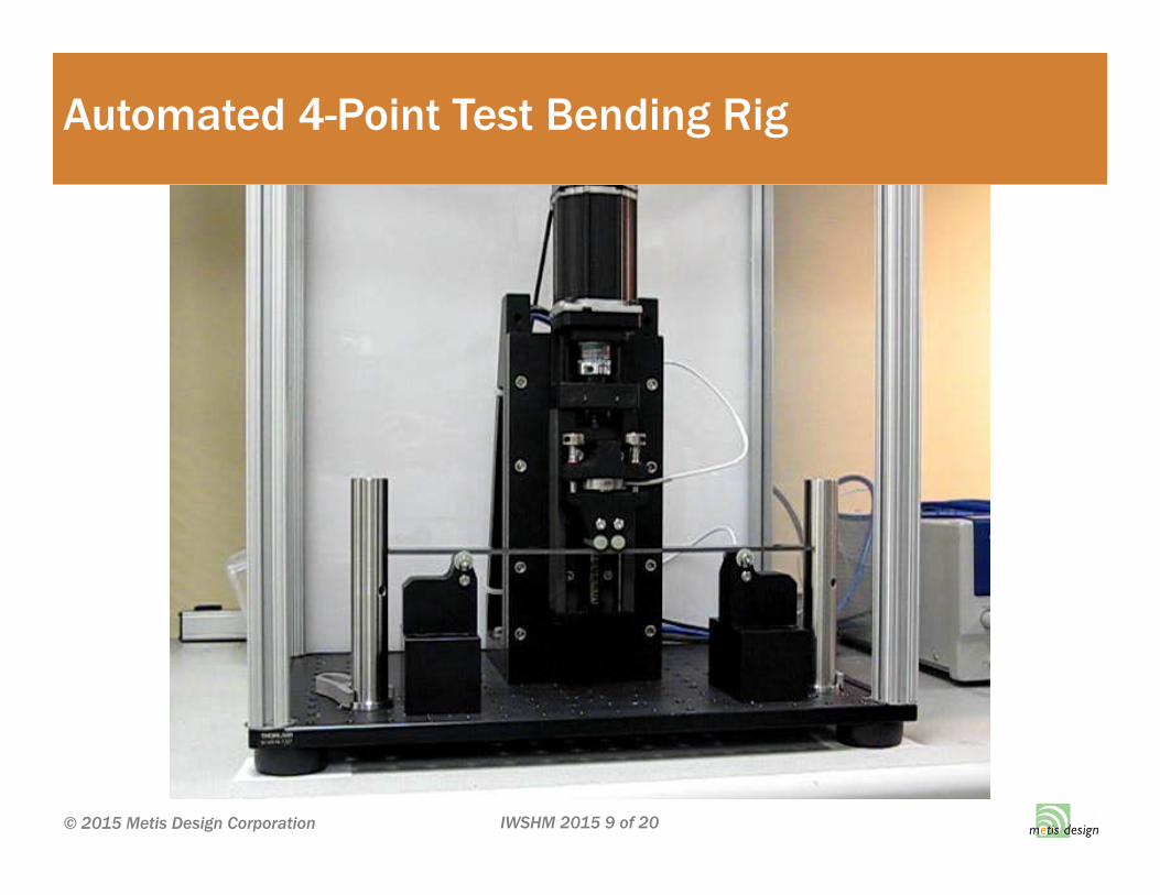
• Enhanced version of basic 4-point setup from prior tests Rather than static load, used Labview-controlled stepper-motor
In-situ monitoring of load, displacement, temp, strain, CNT resistance
1 Hz cycle rate if collecting data, 10 Hz if no data during cycles
• Same setup used for 3 sets of tests, 3 repetitions for each Monitor resistance with various electrode materials & coatings
Monitor resistance with various temperature steps
Strain (enforced)
Fatigue
Creep
Environmental & Mechanical Studies (N111-067)
© 2015 Metis Design Corporation
IWSHM 2015 7 of 20
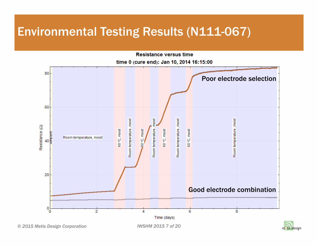
Environmental Testing Results (N111-067)
© 2015 Metis Design Corporation
Good electrode combination
Poor electrode selection

IWSHM 2015 8 of 20
Compensation for (temp.) & (hum.) (N111-067)
© 2015 Metis Design Corporation
IWSHM 2015 9 of 20
Automated 4-Point Test Bending Rig
© 2015 Metis Design Corporation

IWSHM 2015 10 of 20
Enforced Strain Results (N111-067)
© 2015 Metis Design Corporation

IWSHM 2015 11 of 20
Fatigue Test Results (N111-067)
© 2015 Metis Design Corporation

IWSHM 2015 12 of 20
Creep Test Results (N111-067)
© 2015 Metis Design Corporation

IWSHM 2015 13 of 20
CNT based Continuum Crack Gauge (AF141-065)
© 2015 Metis Design Corporation
• Targeted detection of flaw growth in known location Addressing fleetwide problems or critical locations
Alternative to traditional crack gauge
Focus on crack growth in metallic parts for fixed-wing aircraft
• Proposed CNT solution Small (5x5 cm) CNT patch with electrodes around perimeter
Ability to detect fatigue crack, estimate length & orientation
Non-contact resistance measurements for difficult to access locations
• Phase I Study Funded by AFRL, partnered with LMCO – JSF
Calibrated milled-notch results
Demonstrated fatigue crack growth monitoring
Demonstrated passive wireless data acquisition

IWSHM 2015 14 of 20
Continuum Crack Gauge Model (AF141-065)
© 2015 Metis Design Corporation

IWSHM 2015 15 of 20
Continuum Crack Gauge Calibration (AF141-065)
© 2015 Metis Design Corporation
Size of single element in model
Max error ~ 5 mil overprediction

IWSHM 2015 16 of 20
Continuum Crack Gauge Experiment (AF141-065)
© 2015 Metis Design Corporation

IWSHM 2015 17 of 20
Passive RFID Proof-of-Concept (AF141-065)
© 2015 Metis Design Corporation

IWSHM 2015 18 of 20
• Use of CNT as sensing method previously explored w/Navy SBIR Showed strong correlation to tensile/compressive strain loads
Clear trends observed for impact, notch & overload damage
• Durability of approach was investigated Identified/eliminated sources of drift to improve sensitivity/reliability
Quantified/compensated for effects of temperature & moisture absorption
Explored repeatability under strain, observed no effects of creep & fatigue
• Demonstrated continuum crack gauge w/AFRL SBIR Simple model in close agreement with experimental results
Could calibrate crack length & orientation from orthogonal electrodes
Grew real fatigue cracks in 3 specimens, accurate crack length predictions
Proof-of concept demo measured resistance change with RFID approach
CNT Continuum Crack Gauge Summary
© 2015 Metis Design Corporation

IWSHM 2015 19 of 20
• Task 1: Sensor Optimization. materials & fabrication procedure selection. Downselect installation (including self-curing)
• Task 2: RFID Hardware Development. Design, fabricate & test send/receive hardware for collecting data and displaying results
• Task 3: Sensor Calibration & Validation. Conduct several coupon-scale tests to build calibration table for crack size/orientation
• Task 4: Initial Probability of Detection Report. Conduct a first pass PoD assessment for the optimized sensor (MIL-HDBK-1823A)
• Task 5: Durability Assessment. Conduct MIL-STD-810G to determine susceptibility to aircraft environmental conditions
• Task 6: Blind Demonstration. Working with LMCO demonstrate technique blindly on a large F-35 relevant built-up test article
Future Work (AFRL Phase II SBIR)
© 2015 Metis Design Corporation
IWSHM 2015 20 of 20
Technical & Business Contact
Seth S. Kessler, Ph.D. President/CEO Metis Design Corporation617-447-2172 x203 617-308-6743 (cell) [email protected]
© 2015 Metis Design Corporation