CAMUS DYNAFORCE BOILERS - B. G. Peterson...
22
Edited 9/1/2015. Information subject to change without notice. See www.camus‐hydronics.com for the most current information. Page | 1 CAMUS DYNAFORCE BOILERS Up to 99% Thermally Efficient Stainless Steel Heat Exchanger 18 Models: 300-5,000 mbh Hydronic Heating or Domestic Water Category 2 or 4 Natural and/or L.P. Gas Low Nox Standard Energy Management Controls Modbus, optional BACnet or Lonworks Sola HD 7” Touch Screen Standard or ECM Boiler Primary Pump Small Foot Print _________________________________________________ Pg. 2 Boiler BTUH Ranges Flows-Pressure Drops-Temp. Rises Pg. 3 Dimensions, Revit Drawings Pg. 4 Boiler Pump Recommendations Pg. 5 Primary/Secondary Piping Pg. 6-7 Piping with Hydraulic Separator Pg. 8 Venting Options and Sizes Pg. 9 Venting Material and Terminations Pg. 10 Venting Materials Pg. 10 Operating Temperatures and Pressures Pg. 11 Clearances: Service & to Combustibles Pg. 12 Electrical Requirements Pg. 13 Electric Control Wiring Pg. 14-15 Field Wiring BMS and Cascade Pg. 16 Field Wiring of Low Water Cutoff Pg. 17 SOLA Energy Management Control Pg. 18-21 Specifications Pg. 22 Warranty
Transcript of CAMUS DYNAFORCE BOILERS - B. G. Peterson...

Edited 9/1/2015. Information subject to change without notice. See www.camus‐hydronics.com for the most current information.
P a g e | 1
CAMUS DYNAFORCE BOILERS
Up to 99% Thermally Efficient Stainless Steel Heat Exchanger 18 Models: 300-5,000 mbh Hydronic Heating or Domestic Water Category 2 or 4 Natural and/or L.P. Gas Low Nox Standard Energy Management Controls Modbus, optional BACnet or Lonworks Sola HD 7” Touch Screen Standard or ECM Boiler Primary Pump Small Foot Print
_________________________________________________
Pg. 2 Boiler BTUH Ranges Flows-Pressure Drops-Temp. Rises Pg. 3 Dimensions, Revit Drawings Pg. 4 Boiler Pump Recommendations Pg. 5 Primary/Secondary Piping Pg. 6 -7 Piping with Hydraulic Separator Pg. 8 Venting Options and Sizes Pg. 9 Venting Material and Terminations Pg. 10 Venting Materials Pg. 10 Operating Temperatures and Pressures Pg. 11 Clearances: Service & to Combustibles Pg. 12 Electrical Requirements Pg. 13 Electric Control Wiring Pg. 14-15 Field Wiring BMS and Cascade Pg. 16 Field Wiring of Low Water Cutoff Pg. 17 SOLA Energy Management Control Pg. 18-21 Specifications Pg. 22 Warranty
Edited 9/1/2015. Information subject to change without notice. See www.camus‐hydronics.com for the most current information.
P a g e | 2
CAMUS DYNAFORCE BOILERS
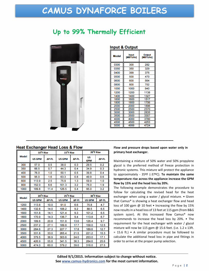
Up to 99% Thermally Efficient
_________________________________________________
Flow and pressure drops based upon water only in
primary heat exchanger.
Maintaining a mixture of 50% water and 50% propylene
glycol is the preferred method of freeze protection in
hydronic systems. This mixture will protect the appliance
to approximately ‐ 35ºF (‐37ºC). To maintain the same
temperature rise across the appliance increase the GPM
flow by 15% and the head loss by 20%.
The following example demonstrates the procedure to
follow for calculating the revised head for the heat
exchanger when using a water / glycol mixture. • Given
that Camus® is showing a heat exchanger flow and head
loss of 100 gpm @ 10 feet • Increasing the flow by 15%
now results in a head loss of 13 feet at 115 gpm (from B&G
system syzer). At this increased flow Camus® now
recommends to increase the head loss by 20%. • The
requirement for the heat exchanger with water / glycol
mixture will now be 115 gpm @ 15.6 feet. (i.e. 1.2 x 13ft.
= 15.6 ft.) • A similar procedure must be followed to
calculate the additional head loss in pipe and fittings in
order to arrive at the proper pump selection.
Edited 9/1/2015. Information subject to change without notice. See www.camus‐hydronics.com for the most current information.
P a g e | 3
CAMUS DYNAFORCE BOILERS
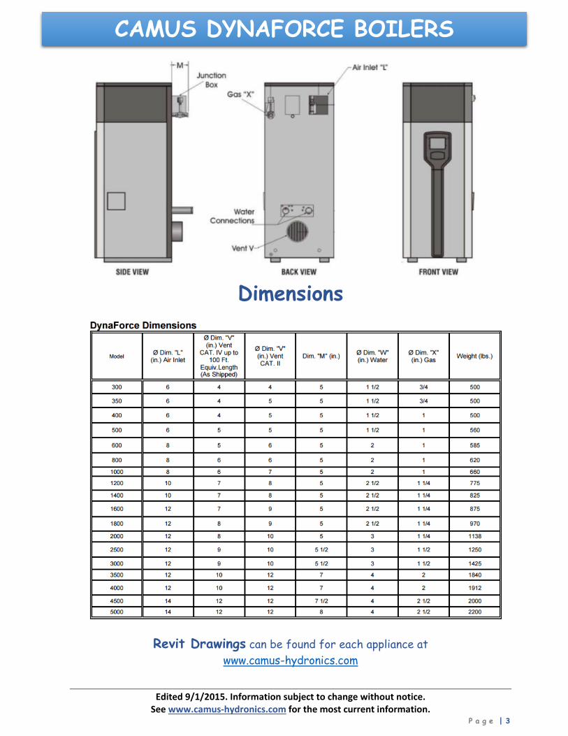
Dimensions
Revit Drawings can be found for each appliance at www.camus-hydronics.com
Edited 9/1/2015. Information subject to change without notice. See www.camus‐hydronics.com for the most current information.
P a g e | 4
CAMUS DYNAFORCE BOILERS
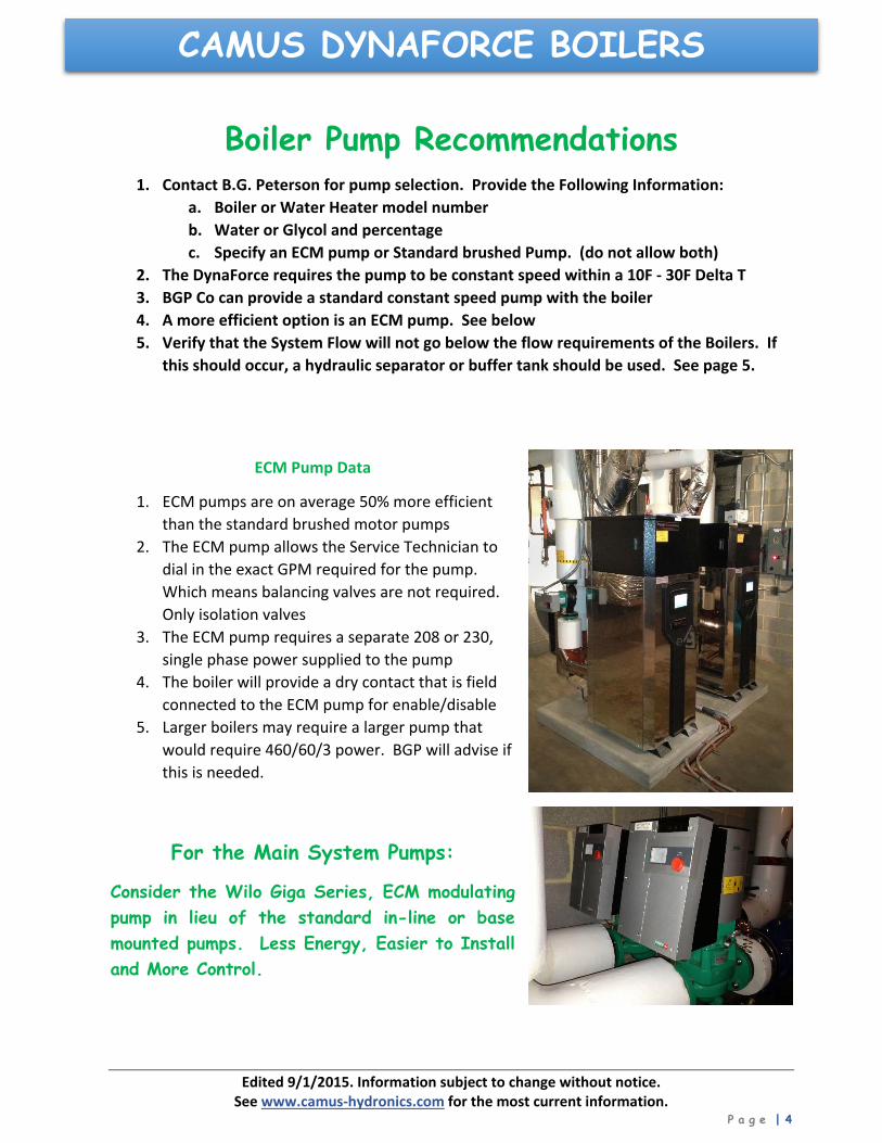
Boiler Pump Recommendations 1. Contact B.G. Peterson for pump selection. Provide the Following Information:
a. Boiler or Water Heater model number
b. Water or Glycol and percentage
c. Specify an ECM pump or Standard brushed Pump. (do not allow both)
2. The DynaForce requires the pump to be constant speed within a 10F ‐ 30F Delta T
3. BGP Co can provide a standard constant speed pump with the boiler
4. A more efficient option is an ECM pump. See below
5. Verify that the System Flow will not go below the flow requirements of the Boilers. If
this should occur, a hydraulic separator or buffer tank should be used. See page 5.
ECM Pump Data
1. ECM pumps are on average 50% more efficient
than the standard brushed motor pumps
2. The ECM pump allows the Service Technician to
dial in the exact GPM required for the pump.
Which means balancing valves are not required.
Only isolation valves
3. The ECM pump requires a separate 208 or 230,
single phase power supplied to the pump
4. The boiler will provide a dry contact that is field
connected to the ECM pump for enable/disable
5. Larger boilers may require a larger pump that
would require 460/60/3 power. BGP will advise if
this is needed.
For the Main System Pumps:
Consider the Wilo Giga Series, ECM modulating pump in lieu of the standard in-line or base mounted pumps. Less Energy, Easier to Install and More Control.

Edited 9/1/2015. Information subject to change without notice. See www.camus‐hydronics.com for the most current information.
P a g e | 5
CAMUS DYNAFORCE BOILERSPrimary/Secondary Piping
Edited 9/1/2015. Information subject to change without notice. See www.camus‐hydronics.com for the most current information.
P a g e | 6
CAMUS DYNAFORCE BOILERS
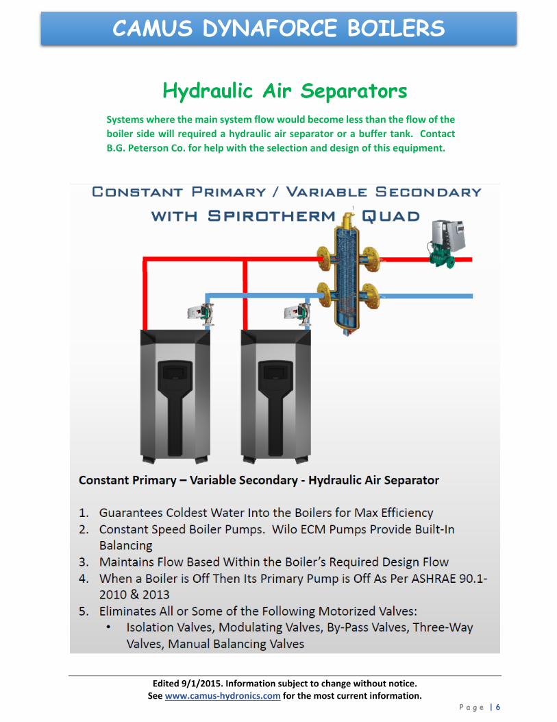
Hydraulic Air Separators Systems where the main system flow would become less than the flow of the
boiler side will required a hydraulic air separator or a buffer tank. Contact
B.G. Peterson Co. for help with the selection and design of this equipment.

Edited 9/1/2015. Information subject to change without notice. See www.camus‐hydronics.com for the most current information.
P a g e | 7
CAMUS DYNAFORCE BOILERS
Hydraulic Air Separators Systems where the main system flow would become less than the flow of the
boiler side will required a hydraulic air separator or a buffer tank. Contact
B.G. Peterson Co. for help with the selection and design of this equipment.
Consult B.G. Peterson Co. for pump sizing and selections.
Edited 9/1/2015. Information subject to change without notice. See www.camus‐hydronics.com for the most current information.
P a g e | 8
CAMUS DYNAFORCE BOILERS
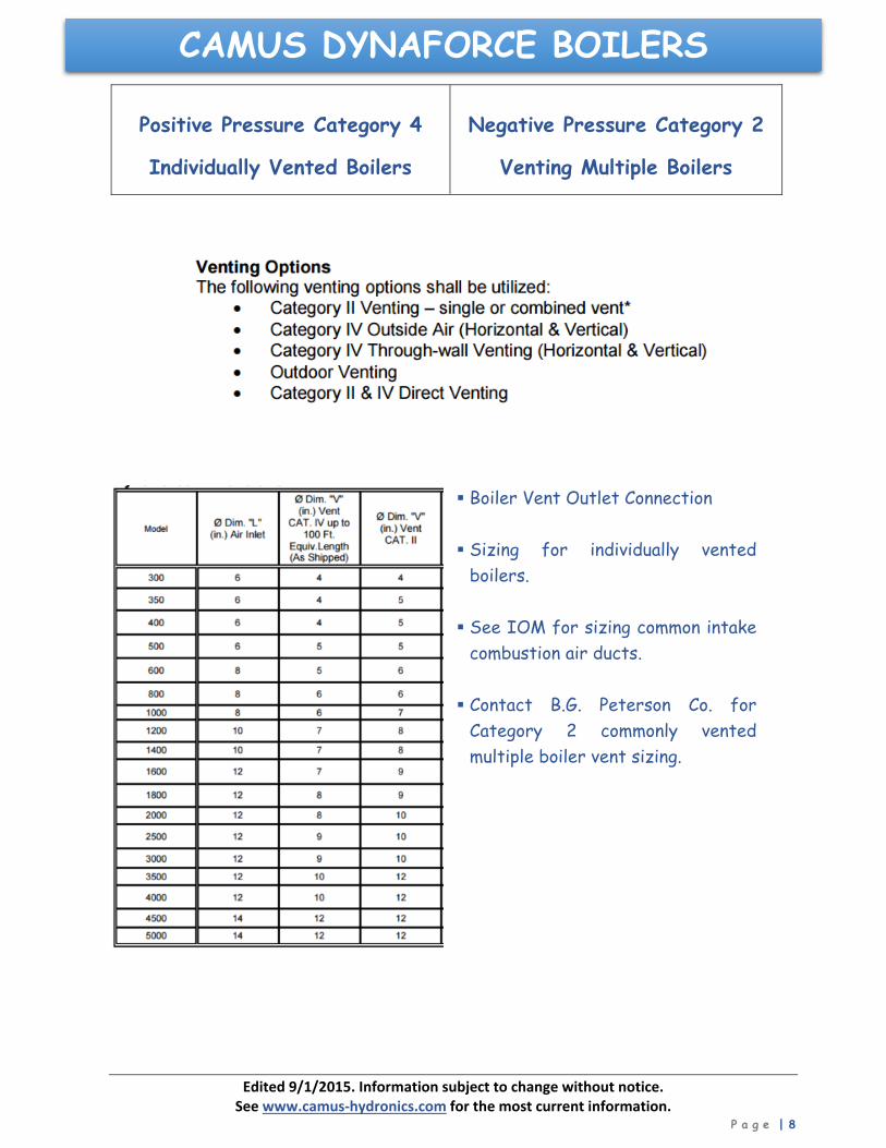
Positive Pressure Category 4
Individually Vented Boilers
Negative Pressure Category 2
Venting Multiple Boilers
Boiler Vent Outlet Connection
Sizing for individually vented
boilers. See IOM for sizing common intake
combustion air ducts. Contact B.G. Peterson Co. for
Category 2 commonly vented multiple boiler vent sizing.

Edited 9/1/2015. Information subject to change without notice. See www.camus‐hydronics.com for the most current information.
P a g e | 9
CAMUS DYNAFORCE BOILERSCombustion Air Intake Duct Material
See IOM, PART 2 for Venting and Intake Guidelines
1. Vent Termination Clearances 2. Location of Rooftop Air Inlet and Vent 3. Optional Air Inlet Damper 4. Masonry Chimney Guidelines 5. Vertical Venting Terminations 6. Combined Combustion Air Inlet Sizing 7. Drain Tee Requirements 8. Air Required For Combustion Air 9. Sidewall Venting Guidelines

Edited 9/1/2015. Information subject to change without notice. See www.camus‐hydronics.com for the most current information.
P a g e | 10
CAMUS DYNAFORCE BOILERSGUIDLEINES FOR VENT MATERIALS
Based upon 100% firing (high Fire) conditions at steady state at 96% Thermal Efficiency.
FLUE MATERIAL MAXIMUM OPERATING TEMPERATURES Material Flue Maximum Operating Temperatures
PVC 149°F
CPVC 194°F
PPE 230°F
AL‐29‐4C (Cat 3) 550°F
Category 3 1,400°F
Category 1 (B) 400°F
Camus Model
Boiler Category
Boiler Flue Material
DynaForce – Single Individually Vented
4
AL‐29‐4CPVC or PPE or CPVC
DynaForce – Multiple Commonly Vented
2
AL‐29‐4CPVC or PPE or CPVC
_________________________________________________
Combustion Air Intake Duct Material
_________________________________________________
Operating Temperatures and Pressures
Note: Minimum allowed return water temperature into the Advantus boiler is 40°F. Stainless Steel Heat Exchanger Boilers Controls Maximum Operating Water Temperature = 200°F
Maximum High Limit Setting = 190°F Operating Pressures Minimum Operating Pressure = 30 psi
Maximum Operating Pressure = 160 psi
Relief Valve Selections (psi) 60, 75, 100, 125, 150, 160 ______________________________________________________________________________________________________________________
Edited 9/1/2015. Information subject to change without notice. See www.camus‐hydronics.com for the most current information.
P a g e | 11
CAMUS DYNAFORCE BOILERS
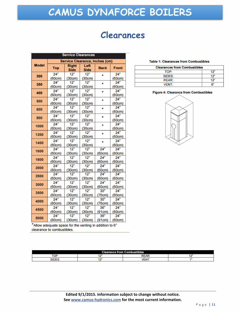
Clearances
Edited 9/1/2015. Information subject to change without notice. See www.camus‐hydronics.com for the most current information.
P a g e | 12
CAMUS DYNAFORCE BOILERS
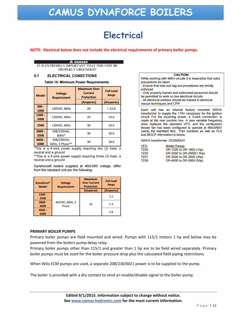
Electrical
NOTE: Electrical below does not include the electrical requirements of primary boiler pumps.
PRIMARY BOILER PUMPS
Primary boiler pumps are field mounted and wired. Pumps with 115/1 motors 1 hp and below may be
powered from the boilers pump delay relay.
Primary boiler pumps other than 115/1 and greater than 1 hp are to be field wired separately. Primary
boiler pumps must be sized for the boiler pressure drop plus the calculated field piping restrictions.
When Wilo ECM pumps are used, a separate 208/230/60/1 power is to be supplied to the pump.
The boiler is provided with a dry contact to send an enable/disable signal to the boiler pump.
Edited 9/1/2015. Information subject to change without notice. See www.camus‐hydronics.com for the most current information.
P a g e | 13
CAMUS DYNAFORCE BOILERS
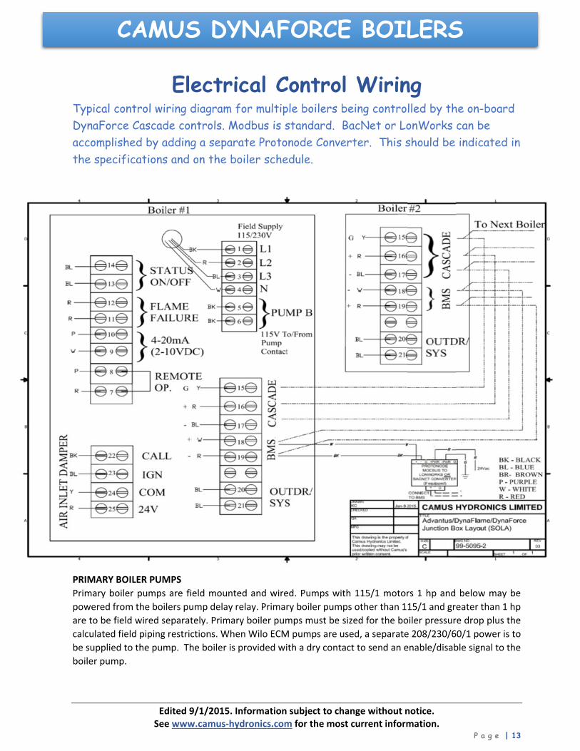
Electrical Control Wiring
Typical control wiring diagram for multiple boilers being controlled by the on-board DynaForce Cascade controls. Modbus is standard. BacNet or LonWorks can be accomplished by adding a separate Protonode Converter. This should be indicated in the specifications and on the boiler schedule.
PRIMARY BOILER PUMPS
Primary boiler pumps are field mounted and wired. Pumps with 115/1 motors 1 hp and below may be
powered from the boilers pump delay relay. Primary boiler pumps other than 115/1 and greater than 1 hp
are to be field wired separately. Primary boiler pumps must be sized for the boiler pressure drop plus the
calculated field piping restrictions. When Wilo ECM pumps are used, a separate 208/230/60/1 power is to
be supplied to the pump. The boiler is provided with a dry contact to send an enable/disable signal to the
boiler pump.
Edited 9/1/2015. Information subject to change without notice. See www.camus‐hydronics.com for the most current information.
P a g e | 14
CAMUS DYNAFORCE BOILERS
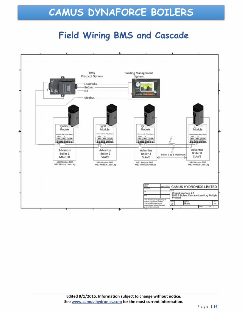
Field Wiring BMS and Cascade
Edited 9/1/2015. Information subject to change without notice. See www.camus‐hydronics.com for the most current information.
P a g e | 15
CAMUS DYNAFORCE BOILERS
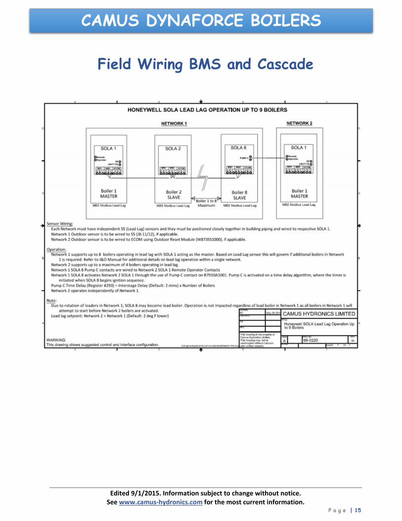
Field Wiring BMS and Cascade

Edited 9/1/2015. Information subject to change without notice. See www.camus‐hydronics.com for the most current information.
P a g e | 16
CAMUS DYNAFORCE BOILERS
Field Wiring of LWCO

Edited 9/1/2015. Information subject to change without notice. See www.camus‐hydronics.com for the most current information.
P a g e | 17
CAMUS DYNAFORCE BOILERS
Edited 9/1/2015. Information subject to change without notice. See www.camus‐hydronics.com for the most current information.
P a g e | 18
CAMUS DYNAFORCE BOILERS
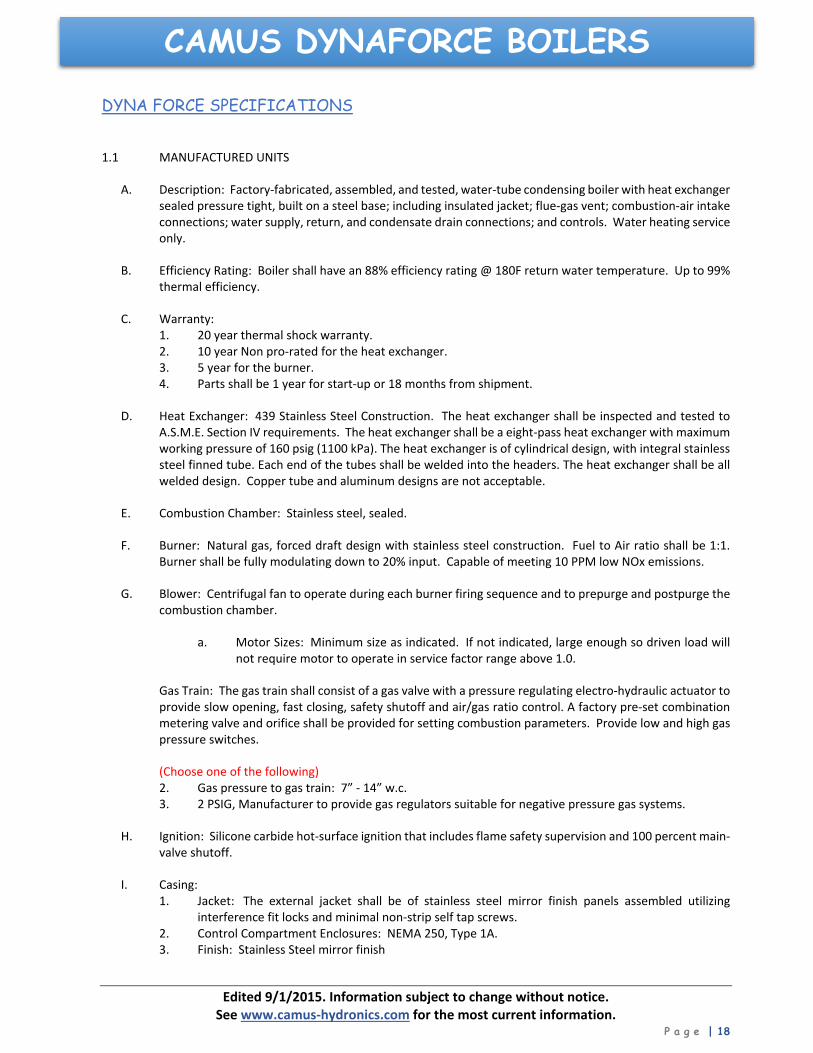
DYNA FORCE SPECIFICATIONS
1.1 MANUFACTURED UNITS
A. Description: Factory‐fabricated, assembled, and tested, water‐tube condensing boiler with heat exchanger sealed pressure tight, built on a steel base; including insulated jacket; flue‐gas vent; combustion‐air intake connections; water supply, return, and condensate drain connections; and controls. Water heating service only.
B. Efficiency Rating: Boiler shall have an 88% efficiency rating @ 180F return water temperature. Up to 99% thermal efficiency.
C. Warranty: 1. 20 year thermal shock warranty. 2. 10 year Non pro‐rated for the heat exchanger. 3. 5 year for the burner. 4. Parts shall be 1 year for start‐up or 18 months from shipment.
D. Heat Exchanger: 439 Stainless Steel Construction. The heat exchanger shall be inspected and tested to A.S.M.E. Section IV requirements. The heat exchanger shall be a eight‐pass heat exchanger with maximum working pressure of 160 psig (1100 kPa). The heat exchanger is of cylindrical design, with integral stainless steel finned tube. Each end of the tubes shall be welded into the headers. The heat exchanger shall be all welded design. Copper tube and aluminum designs are not acceptable.
E. Combustion Chamber: Stainless steel, sealed.
F. Burner: Natural gas, forced draft design with stainless steel construction. Fuel to Air ratio shall be 1:1. Burner shall be fully modulating down to 20% input. Capable of meeting 10 PPM low NOx emissions.
G. Blower: Centrifugal fan to operate during each burner firing sequence and to prepurge and postpurge the combustion chamber.
a. Motor Sizes: Minimum size as indicated. If not indicated, large enough so driven load will not require motor to operate in service factor range above 1.0.
Gas Train: The gas train shall consist of a gas valve with a pressure regulating electro‐hydraulic actuator to provide slow opening, fast closing, safety shutoff and air/gas ratio control. A factory pre‐set combination metering valve and orifice shall be provided for setting combustion parameters. Provide low and high gas pressure switches.
(Choose one of the following) 2. Gas pressure to gas train: 7” ‐ 14” w.c. 3. 2 PSIG, Manufacturer to provide gas regulators suitable for negative pressure gas systems.
H. Ignition: Silicone carbide hot‐surface ignition that includes flame safety supervision and 100 percent main‐valve shutoff.
I. Casing: 1. Jacket: The external jacket shall be of stainless steel mirror finish panels assembled utilizing
interference fit locks and minimal non‐strip self tap screws. 2. Control Compartment Enclosures: NEMA 250, Type 1A. 3. Finish: Stainless Steel mirror finish
Edited 9/1/2015. Information subject to change without notice. See www.camus‐hydronics.com for the most current information.
P a g e | 19
CAMUS DYNAFORCE BOILERS4. Insulation: Mineral‐fiber insulation surrounding the heat exchanger. 5. Combustion‐Air Connections: Inlet and vent duct collars. 6. Mounting base to secure boiler.
1.2 TRIM
A. Include devices sized to comply with [ANSI B31.1, "Power Piping [ANSI B31.9, "Building Services Piping”].
B. Aquastat Controllers: Modulating Operator and high limit.
C. Safety Relief Valve: ASME rated.
D. Pressure and Temperature Gage: Combination water‐pressure and ‐temperature gage. Gages shall have operating‐pressure and ‐temperature ranges so normal operating range is about 50 percent of full range.
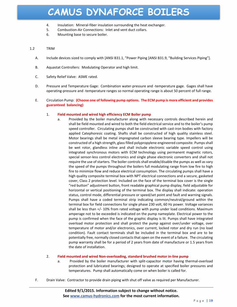
E. Circulation Pump: (Choose one of following pump options. The ECM pump is more efficient and provides guaranteed balancing)
1. Field mounted and wired high efficiency ECM Boiler pump
a. Provided by the boiler manufacturer along with necessary controls described herein and shall be field mounted and wired to both the field electrical service and to the boiler’s pump speed controller. Circulating pumps shall be constructed with cast‐iron bodies with factory applied Catephoresic coating. Shafts shall be constructed of high quality stainless steel. Motor bearings shall be metal impregnated carbon sleeve bearing type. Impellers will be constructed of a high strength, glass filled polypropylene engineered composite. Pumps shall be wet rotor, glandless inline and shall include electronic variable speed control using integrated synchronous motors with ECM technology using permanent magnetic rotors, special sensor‐less control electronics and single phase electronic converters and shall not require the use of starters. The boiler controls shall enable/disable the pumps as well as vary the speed of the pumps throughout the boilers full modulating range from low fire to high fire to minimize flow and reduce electrical consumption. The circulating pumps shall have a high quality composite terminal box with NPT electrical connections and a secure, gasketed cover, Class 2 protection level. Included on the face of the terminal box cover is the single “red button” adjustment button, front readable graphical pump display, field adjustable for horizontal or vertical positioning of the terminal box. The display shall indicate: operation status, control mode, differential pressure or speed/set point and fault and warning signals. Pumps shall have a coded terminal strip indicating common/neutral/ground within the terminal box for field connections for single phase 230 volt, 60 Hz power. Voltage variances shall be less than +/‐ 10% from rated voltage with pump under load conditions. Maximum amperage not to be exceeded is indicated on the pump nameplate. Electrical power to the pump is confirmed when the face of the graphic display is lit. Pumps shall have integrated overload motor protection and shall protect the pump against over/under voltage, over temperature of motor and/or electronics, over current, locked rotor and dry run (no load condition). Fault contact terminals shall be included in the terminal box and are to be potentially free, normally closed contacts that open on the event of a failure. The circulating pump warranty shall be for a period of 2 years from date of manufacture or 1.5 years from the date of installation.
2. Field mounted and wired Non‐overloading, standard brushed motor in‐line pump
a. Provided by the boiler manufacturer with split‐capacitor motor having thermal‐overload protection and lubricated bearings; designed to operate at specified boiler pressures and temperatures. Pump shall automatically come on when boiler is called for.
F. Drain Valve: Contractor to provide drain piping with shut off valve as required per Manufacturer.

Edited 9/1/2015. Information subject to change without notice. See www.camus‐hydronics.com for the most current information.
P a g e | 20
CAMUS DYNAFORCE BOILERS
CONTINUED
1.3 CONTROLS Standard controls include a SOLA 7” color touch screen electronic proportional integrated combination limit/operator control accurate to 10F (0.50C) having a 4‐20 mA output signal suitable for control of a variable frequency motor drive.
A. This controller offers a range of operation modes which provides set point as well as modulating control. It provides the following:
a. Readings of inlet and outlet water temperatures as well as flame signal. b. Operation as an auto reset limit. c. Operation as a control for inlet water temperature, outlet temperature, system temperature. d. 40F ΔT heat exchanger protection algorithm e. Available tank mounted sensor used in conjunction with inlet sensor. f. Adjustable; target temp, inter‐stage differential, on delay between stages, minimum on time per
stage, minimum off time per stage. g. Display of run hours for maintenance purposes. Counter wraps around at 10000 hours. h. Flame failure signal. i. Lumberg and Molex connectors for ease of service. j. Error message display in text k. Manual override of boiler input rate for combustion l. Pump exercising feature runs pump 10 seconds every three days in the event of no pump operation.
B. Boiler mounted control is capable of controlling up to 8 boilers in a cascade arrangement. No wall mounted panel is required. The following components are needed for a Lead Lag setup:
a. System Sensor located in the supply side of the common boiler piping. Outdoor air sensor. C. Sequence of Operation: When a boiler is set as Lead Lag Master = Enabled and Modbus address = 1, the
controller of this boiler will drive the lead lag operation. The outdoor temperature sensor connected to the slave boiler 2 (ie. B‐2) will be the outdoor sensor for the lead lag system. The system temperature sensor connected to boiler 1 in terminals labeled “Outdr/Sys” in the function box will be the control sensor for lead lag operation. The start/stop signal connected to boiler 1 at terminals labeled “Remote Operator” will be the heat demand input for lead lag operation. When demand for heat is present the lead boiler will start and uses the lead lag parameters for boiler modulation.
a. After a period of “Interstage delay” the master boiler compares the lead lag temperature with the lead lag set point and will check if:
i. An additional boiler is needed ii. Number of boilers remain the same iii. A boiler should stop
b. Rotation: Rotation time is configurable based on equalized run time (default) or a fixed rotation schedule.
c. Interstage Delay: The length of time to wait between requesting a slave SOLA to fire and detecting that it has failed to start. (Default: 2 minutes)
d. Base Load Rate: When a call for heat is initiated the lead boiler runs at the desired base load rate (Default: 80%) and continues to operate in this fashion based on the above 3 scenarios. If the lead lag temperature is not satisfied a second boiler is fired at they would both operate at 80% fire rate.
A. Safety Controls:
1. High Cutoff: Manual reset stops burner if operating conditions rise above maximum boiler design [210F]
2. Low‐Water Cutoff Switch: Electronic probe shall prevent burner operation on low water. Cutoff switch shall be manual reset type. Field wired and mounted as per IOM.
3. Blocked Inlet Safety Switch: Manual‐reset pressure switch field mounted on boiler combustion‐air inlet.
Edited 9/1/2015. Information subject to change without notice. See www.camus‐hydronics.com for the most current information.
P a g e | 21
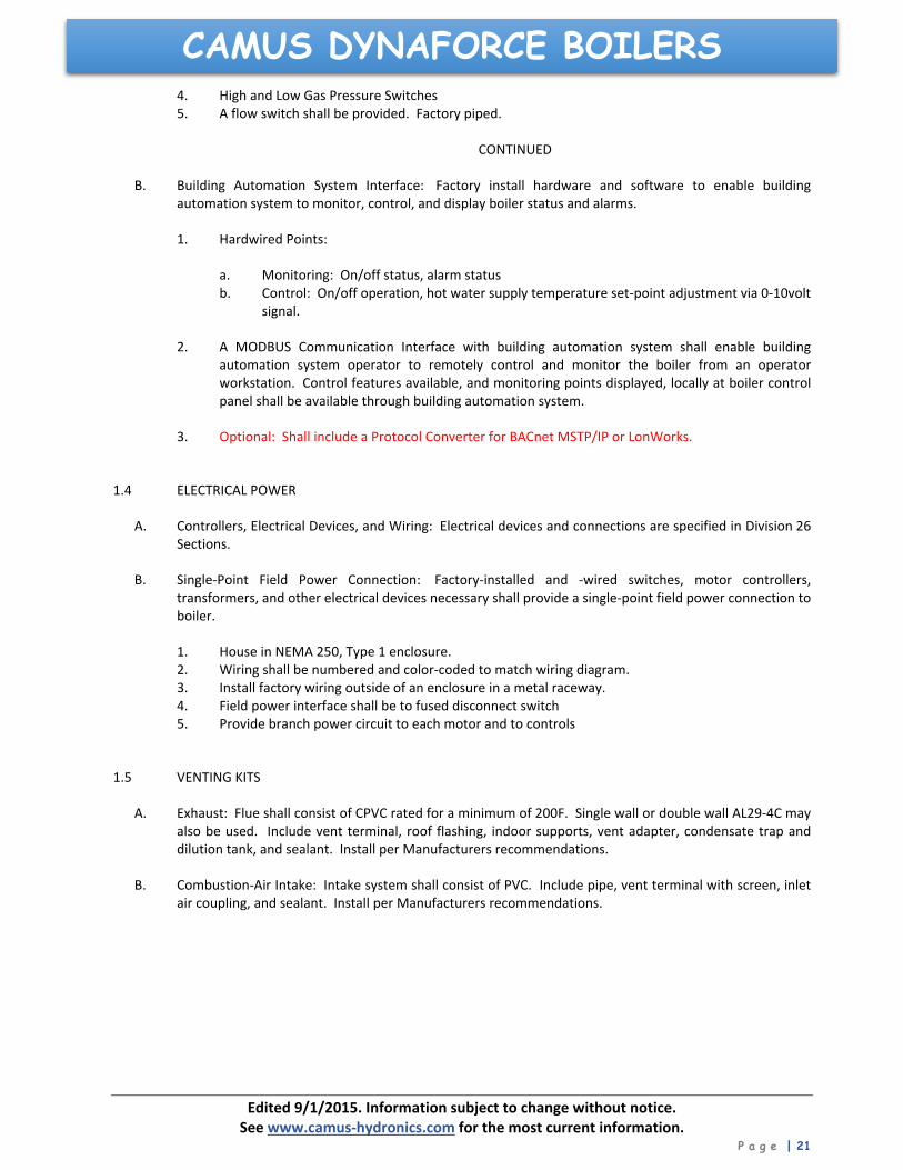
CAMUS DYNAFORCE BOILERS4. High and Low Gas Pressure Switches 5. A flow switch shall be provided. Factory piped.
CONTINUED
B. Building Automation System Interface: Factory install hardware and software to enable building automation system to monitor, control, and display boiler status and alarms.
1. Hardwired Points:
a. Monitoring: On/off status, alarm status b. Control: On/off operation, hot water supply temperature set‐point adjustment via 0‐10volt
signal.
2. A MODBUS Communication Interface with building automation system shall enable building automation system operator to remotely control and monitor the boiler from an operator workstation. Control features available, and monitoring points displayed, locally at boiler control panel shall be available through building automation system.
3. Optional: Shall include a Protocol Converter for BACnet MSTP/IP or LonWorks.
1.4 ELECTRICAL POWER
A. Controllers, Electrical Devices, and Wiring: Electrical devices and connections are specified in Division 26 Sections.
B. Single‐Point Field Power Connection: Factory‐installed and ‐wired switches, motor controllers, transformers, and other electrical devices necessary shall provide a single‐point field power connection to boiler.
1. House in NEMA 250, Type 1 enclosure. 2. Wiring shall be numbered and color‐coded to match wiring diagram. 3. Install factory wiring outside of an enclosure in a metal raceway. 4. Field power interface shall be to fused disconnect switch 5. Provide branch power circuit to each motor and to controls
1.5 VENTING KITS
A. Exhaust: Flue shall consist of CPVC rated for a minimum of 200F. Single wall or double wall AL29‐4C may also be used. Include vent terminal, roof flashing, indoor supports, vent adapter, condensate trap and dilution tank, and sealant. Install per Manufacturers recommendations.
B. Combustion‐Air Intake: Intake system shall consist of PVC. Include pipe, vent terminal with screen, inlet air coupling, and sealant. Install per Manufacturers recommendations.

78
CONDENSING BOILER LIMITED WARRANTY GENERAL
Camus® Hydronics Limited (“Camus®”) extends the following LIMITED WARRANTY to the owner of this appliance, provided that the product has been installed and operated in accordance with the Installation Manual provided with the equipment. Camus® will furnish a replacement for, or at Camus® option repair, any part that within the period specified below, shall fail in normal use and service at its original installation location due to any defect in workmanship, material or design. The repaired or replacement part will be warranted for only the unexpired portion of the original warranty. This limited warranty does not cover failures or malfunctions resulting from: (1) Failure to properly install, operate or maintain the equipment in accordance with Camus®’ manual; (2) Abuse, alteration, accident, fire, flood, foundation problems and the like; (3) Sediment or lime build-up, freezing, or other conditions causing inadequate water circulation; (4) Pitting and erosion caused by high water velocity; (5) Failure of connected systems devices, such as pump or controller; (6) Use of non-factory authorized accessories or other components in conjunction with the system; (7) failing to eliminate air from, or replenish water in, the connected water system; (8) Chemical contamination of combustion air or use of chemical additives to water; (9) Production of noise, odours, discolouration or rusty water; (10) Damage to surrounds or property caused by leakage or malfunction; (11) All labour costs associated with the replacement and/or repair of the unit; (12) Any failed component of the hydronic system not manufactured as part of the boiler. HEAT EXCHANGER
Within 10 years of the appliance having declared FOB from Camus®, a heat exchanger shall prove upon examination by Camus® to be defective in material or workmanship, Camus® will exchange or repair such part or portion if deemed warranty based on the number of years the appliance has been in service.
Years In
Service Dynaforce®
Years In
Service Dynaforce®
1 100% 6 100%
2 100% 7 100%
3 100% 8 100%
4 100% 9 100%
5 100% 10 100%
The exchanged or repaired heat exchanger will carry the balance of the remaining original warranty provided with the appliance based on the FOB date. In the event a replacement heat exchanger is delivered and if the defective heat exchanger is deemed to be repairable by Camus® the repaired heat exchanger will be returned to the customer and a credit will not be issued. Heat Exchanger shall be warranted for (20) years of the appliance having declared FOB from Camus® against “Thermal Shock” (excluded, however, if caused by appliance operation at large changes exceeding 150ºF between the water temperature at inlet and appliance temperature or operating at temperatures exceeding 210oF (DRH & DRW). BURNER
If within FIVE years of the appliance having declared FOB from Camus® to be defective in material or workmanship, Camus® will exchange or repair such part or portion. ANY OTHER PART
If any other part fails within one (1) year after installation, or eighteen (18) months of the appliance having declared FOB from Camus® whichever comes first Camus® will furnish a replacement or repair that part. Replacement parts will be shipped FOB our factory.
DURATION OF LIMITED WARRANTY
Any limited warranty, including the warranty of merchantability imposed on the sale of the boiler under the laws of the state or province of sale are limited in duration to one year from date of original installation. STATE LAW & LIMITED WARRANTY
Some states or provinces do not allow: a. Limitations on how long an implied warranty lasts b. Limitations on incidental or consequential damages. The listed limitations may or may not apply to you. This warranty gives you specific legal rights, and you may also have other rights which may vary from state to state and province to province.
CONDITIONS
We will not: a) Repair or replace any boiler, or part, subject to conditions outlined in ‘This Limited Warranty Does Not Cover’ b) Reimburse any costs associated with repair and/or replacement c) Replace and/or repair any boiler without complete model number/serial number d) Replace any boiler without prior receipt of actual rating plate from the appliance.