Calorimeter system C 200 - IKAika.com.my/images/Calorimeter/manual_c_200_e.pdf · Calorimeter...
44
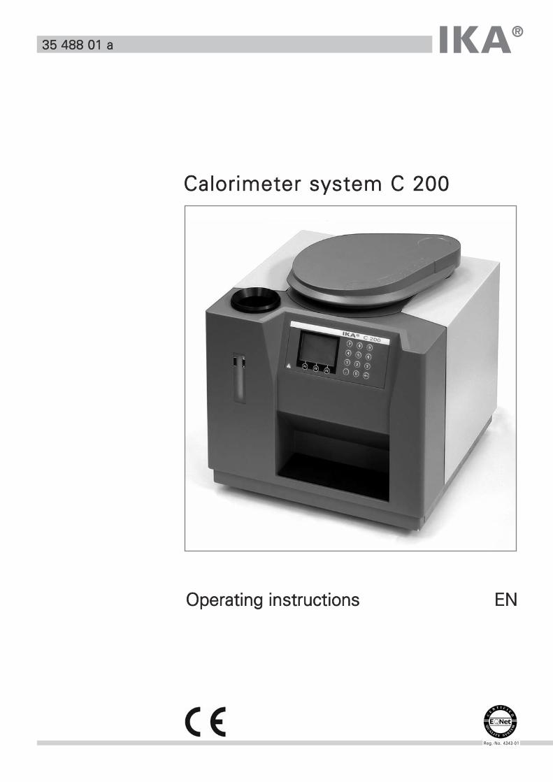
IKA ® Operating instructions EN 35 488 01 a Calorimeter system C 200 Reg.-No. 4343-01
Transcript of Calorimeter system C 200 - IKAika.com.my/images/Calorimeter/manual_c_200_e.pdf · Calorimeter...
IKA®
OOppeerraattiinngg iinnssttrruuccttiioonnss EENN
3355 448888 0011 aa
CCaalloorriimmeetteerr ssyysstteemm CC 220000
Reg.-No. 4343-01

2
Table of contents
Chapter Page
1 Safety precautions 6
2 User information 9
2.1 Information regarding operating instructions 9
2.2 Warranty and liability 9
3 Transport, storage, place of installation 10
3.1 Conditions of transport and storage 10
3.2 Place of installation 10
3.3 Unpacking 10
3.4 Contents C 200 11
4 Installations and starting up 12
4.1 Calorimeter C 200 12
4.2 Installation 12
4.3 Switchin on the system 14
4.4 Display and operating elements 14
4.5 Configuring the system 16
4.6 System settings 17
4.7 Filling the calorimeter for the first time 19
4.8 Switchin off the system 20
4.9 Coding decomposition vessel 20
4.10 Oxygen station C 248 21
5 Calorimetric measurements 22
5.1 Determining the calorific value 22
5.2 Corrections 23
5.3 Information about the sample 24
5.4 Calibration 25
6 Preparing and performing measurements 26
6.1 Decomposition vessel C 5010 26
6.2 Preparing the decomposition vessel 27
6.3 Preparing the measurement 29
6.4 Performing the measurement 30
6.5 Cleaning the decomposition vessel 32
6.6 Errors in the measuring procedure 33
7 Service menue 36
7.1 Operation 36
7.2 Description of service menue options 37
3IKA®- WERKE C200 03.08
Table of contents
Chapter Page
8 Cleaning and maintenance 38
8.1 Inner vessel filter 38
8.2 Filler 38
8.3 Micro filter 38
8.4 Maintaining the water circulation 39
8.5 Decomposition vessels 39
8.6 Cleaning informations 39
9 IKA®- accesories and consumables 40
9.1 Accessories 40
9.2 Consumables 40
10 Technical data 41
4 IKA®- WERKE C200 03.08
IKA®- WERKE C200 03.08
CE – KONFORMITÄTSERKLÄRUNGWir erklären in alleiniger Verantwortung, dass dieses Produkt den Bestimmungen der Richtlinien 89 / 336 EWG; 89 / 392 EWG und 73 / 23 EWG entspricht und mit folgenden Normen und normativen Dokumenten übereinstimmt:EN 61 010; EN 50 082; EN 55 014; EN 60 555.
CE – DECLARATION OF CONFIRMITYWe declare under our sole responsibility that this product corresponds to the regulations 89 / 336 EEC; 89 / 392 EEC and 73 / 23 EEC and conforms with the standards or standardized documents:EN 61 010; EN 50 082; EN 55 014; EN 60 555.
DÉCLARATION DE CONFORMITÉ CENous déclarons sous notre responsabilité que se prodiut est conforme aux réglementations 89 / 336 CEE; 89 / 392 CEE et 73 / 23 CEE et en conformité avec les normes ou documents normalisés suivant:EN 61 010; EN 50 082; EN 55 014; EN 60 555.
DECLARACION DE CONFORMIDAD DE CEDeclaramos por nuestra responsabilidad propia que este produkto corresponde a las directrices 89 / 336 CEE; 89 / 392 CEE y 73 / 23 CEE y que cumple las normas o documentos normativos siguientes:EN 61 010; EN 50 082; EN 55 014; EN 60 555.
CE – DICHIARAZIONE DI CONFORMITÀDichiariamo, assumendone la piena responsabilità, che il prodotto è conforme alle seguentidirettive CCE 89 / 336 ; CCE 89 / 392 e CCE 73 / 23, in accordo ai seguenti regolamenti e documenti: EN 61 010; EN 50 082; EN 55 014; EN 60 555.
DE
EN
FR
ES
IT
5

Safety precautions1
Calorimeter system C 200 may only be used to determine the calorific value of solid andfluid materials. Only the appropriate original IKA® decomposition vessels may be usedfor this purpose. For detailed information, please see the operating instructions for thedecomposition vessels.
The maximum extra energy added to the decomposition vessel must not exceed 40,000 J(select the test mass accordingly). The permitted operating pressure of 230 bar must notbe exceeded. The maximum permitted operating temperature must not exceed 50°C.
Do not overfill the decomposition vessel with sample. Only fill the decomposition vesselwith oxygen to a maximum pressure of 40 bar. Check the set pressure on the pressurereducer. Perform a leakage test before each combustion process (follow operatinginstructions for decomposition vessel!).
Some materials tend to explode when combusted (e.g. due to formation of peroxide),which could cause the decomposition vessel to crack.Standard decomposition vessels may not be used for testing explosive samples.
If the burning behaviour of a material is unknown, it must be tested before combustionin the decomposition vessel (risk of explosion). If you are burning unknown samples,leave the room or keep your distance from the calorimeter.
Benzoic acid may only be combusted in its pressed form! Flammable dust and powdermust be first pressed. Oven-dry dust and powder such as splints, hay, straw etc. explodewhen combusted! Always wet these materials first! Highly flammable liquids with a lowvapour pressure (e.g. tetramethyl dihydrogen disiloxane) must not directly touch the cotton thread!
Furthermore, toxic combustion residue in the form of gases, ashes or condensation, forexample, is possible in the inner wall of the decomposition vessel.
Please observe the accident prevention regulations applicable for the activity and theworkstation. Wear your personal protective equipment.
When handling combustion samples, combustion residue and auxiliary materials, pleaseobserve the relevant safety regulations. The following materials, for example, could pose a risk:
– corrosive– highly flammable– explosive– bacteriologically contaminated– toxic
6 IKA®- WERKE C200 03.08

Please observe the relevant regulations when handling oxygen.Warning: oxygen as a compressed gas is oxidising; intensively aids combustion; canreact violently with flammable materials.Do not use oil or grease!
Caution - magnetism! Beware of effects from the magnetic field (pacemakers, data mediaetc.).
When using stainless steel crucibles thoroughly check their condition after each experi-ment. If the material gets thinner, the crucible may catch fire and damage the decomposi-tion vessel. Crucibles must not be used for more than 25 combustions for safety reasons.
The decomposition vessel is manufactured in accordance with the directive for pressureequipment 97/23/EC. This is indicated by the CE symbol with the ID number of the noti-fied body. The decomposition vessel is a category III pressure device. The decompositionvessel has undergone an EC prototype test. The CE declaration of conformity confirmsthat this decomposition vessel corresponds to the pressure device described in the ECprototype test certificate. The decomposition vessel has undergone a pressure test withthe test pressure of 330 bar and a leakage test with oxygen at 30 bar.Decomposition vessels are experiment autoclaves and must be tested by a technicalexpert after each use.Individual use is understood here to include a series of experiments performed underroughly the same conditions in terms of pressure and temperature. Experiment autocla-ves must be operated in special chambers (C 2000, C 5000, C 7000, C 200).
The decomposition vessels must undergo repeated tests (internal tests and pressuretests) performed by the technical expert. The frequency of these tests is to be determi-ned by the operator on the basis of experience, type of operation and the material usedin the decomposition vesselThe declaration of conformity becomes invalid if mechanical modifications are carriedout to the experiment autoclaves or if tightness can no longer be guaranteed as a resultof major corrosion (e.g. pitting by halogens).The threads on the body of the decomposition vessel and the union nut are subject toconsiderable stress in particular and must therefore be checked regularly for wear.The condition and function of the seals must be checked and ensured by way of a leaka-ge test (see operating instructions for decomposition vessel!).Only technical experts may perform pressure tests and service work on the decomposi-tion vessel
We recommend that you send the decomposition vessel to our factory for inspection,and if necessary, repair after 1000 tests or after one year or sooner depending on use.
7IKA®- WERKE C200 03.08
For the purposes of these operating instructions a technical expert is someone
1. who guarantees to conduct the tests properly on the basis of his training, knowledgeand experience gained through practical work,
2. who is sufficiently reliable,
3. who is not subject to any instructions in terms of the test activity
4. who has suitable test equipment if necessary
5. who can provide appropriate proof of the requirements listed in 1
National directives and laws must be observed for operating pressure vessels!
Anyone operating a pressure vessel must keep it in a proper condition, operate it proper-ly, supervise it, carry out the necessary maintenance and repair work immediately andimplement the safety measures required in the circumstances.Pressure vessels must not be used if they have defects which could pose a risk to staff orthird parties. The pressure equipment directive can be obtained from Carl Heymanns orBeuth publishers.
The C 248 oxygen station must be set up at least 1,5m far away from the calorimeter.
8 IKA®- WERKE C200 03.08
User information2
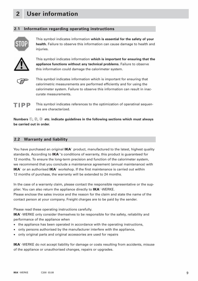
This symbol indicates information which is essential for the safety of yourhealth. Failure to observe this information can cause damage to health andinjuries.
This symbol indicates information which is important for ensuring that theappliance functions without any technical problems. Failure to observethis information could damage the calorimeter system.
This symbol indicates information which is important for ensuring thatcalorimetric measurements are performed efficiently and for using thecalorimeter system. Failure to observe this information can result in inac-curate measurements.
This symbol indicates references to the optimization of operatinal sequen-ces are characterized.
Numbers �, �, � etc. indicate guidelines in the following sections which must alwaysbe carried out in order.
You have purchased an original IKA® product, manufactured to the latest, highest qualitystandards. According to IKA®'s conditions of warranty, this product is guaranteed for 12 months. To ensure the long-term precision and function of the calorimeter system, we recommend that you conclude a maintenance agreement (annual maintenance) withIKA® or an authorised IKA® workshop. If the first maintenance is carried out within 12 months of purchase, the warranty will be extended to 24 months.
In the case of a warranty claim, please contact the responsible representative or the sup-plier. You can also return the appliance directly to IKA®-WERKE.Please enclose the sales invoice and the reason for the claim and state the name of thecontact person at your company. Freight charges are to be paid by the sender.
Please read these operating instructions carefully.IKA®-WERKE only consider themselves to be responsible for the safety, reliability andperformance of the appliance when
• the appliance has been operated in accordance with the operating instructions,
• only persons authorised by the manufacturer interfere with the appliance,
• only original parts and original accessories are used for repairs
IKA®-WERKE do not accept liability for damage or costs resulting from accidents, misuseof the appliance or unauthorised changes, repairs or upgrades.
2.1 Information regarding operating instructions
2.2 Warranty and liability
TIPP
9IKA®- WERKE C200 03.08
Transport, storage, place of installation3
The system must be protected against mechanical impact, vibrations, dust deposits andcorrosive ambient air during transportation and storage.It is also important to ensure that the relative humidity does not exceed 80%.Only the original packing may be used for transportation.The appliance must be completely emptied before storing and transportation.
Please observe the respective country-specific regulations for operating pressure equip-ment when installing the appliance.A constant ambient temperature is an important requirement for ensuring the high mea-suring accuracy of the system. The following conditions must therefore be fulfilled at theplace of installation:
• No direct solar radiation
• No draughts (e.g. beside windows, doors, air conditioning)
• Sufficient distance to radiators and other heat sources
• The (constant) room temperature should be around 20 °C ... 25 °C.
• The system must be installed on a level surface.
• An adequate power supply corresponding to the nameplates on the system compo-nents.
• Oxygen supply (99.95 % pure oxygen, quality 3.5; pressure 30 bar) with pressuredisplay and shut-off device. (C29 reducing valve, accessories)
Please unpack the system components carefully and check for any damage. When youunpack the equipment, check for any damages which may have occurred during trans-portation. Make a note of any damage and report it immediately (post, railway, shippingcompany).
3.1 Conditions of transport and storage
3.2 Place of installation
3.3 Unpacking
10 IKA®- WERKE C200 03.08
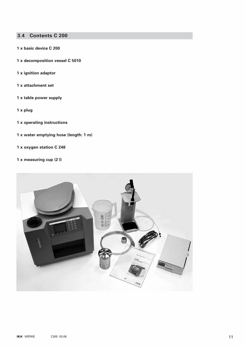
1 x basic device C 200
1 x decomposition vessel C 5010
1 x ignition adaptor
1 x attachment set
1 x table power supply
1 x plug
1 x operating instructions
1 x water emptying hose (length: 1 m)
1 x oxygen station C 248
1 x measuring cup (2 l)
3.4 Contents C 200
11IKA®- WERKE C200 03.08

Installation and starting up4
� measuring cell cover
� tank fillers
� display
� keyboard
� fill level display
All the connections for draining as well as the peripherals are on the back of the appliance.
� Connecting the plugConnect the calorimeter to the plug (4-pin plug �).Check that the voltage information on the rating plate of the power supply unit matchesyour mains supply.Connect the power line of the plug to the voltage source.
� Connecting peripheralsWhen connecting peripherals make sure that both they and the calorimeter are swit-ched off at ON/OFF switch �.
4.1 Calorimeter C 200
� PC connector
� printer connector
� ON/OFF switch
� plug connector
� plug
4.2 Installation
12 IKA®- WERKE C200 03.08
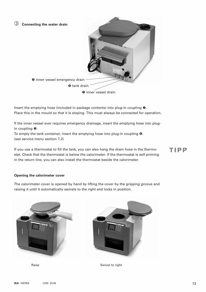
� Connecting the water drain
Insert the emptying hose (included in package contents) into plug-in coupling . Place this in the mould so that it is sloping. This must always be connected for operation.
If the inner vessel ever requires emergency drainage, insert the emptying hose into plug-in coupling �.To empty the tank container, insert the emptying hose into plug-in coupling �.(see service menu section 7.2)
If you use a thermostat to fill the tank, you can also hang the drain hose in the thermo-stat. Check that the thermostat is below the calorimeter. If the thermostat is self-primingin the return line, you can also install the thermostat beside the calorimeter.
Opening the calorimeter cover
The calorimeter cover is opened by hand by lifting the cover by the gripping groove andraising it until it automatically swivels to the right and locks in position.
Raise Swivel to right
TIPP
� inner vessel emergency drain
� tank drain
inner vessel drain
13IKA®- WERKE C200 03.08

Switch the calorimeter on at ON/OFF switch � (back of appliance).The appliance is now in standby mode.
Press ON (F1) to work with the appliance. The start screen will appear. The operating console features the following elements:
� Status line: shows the current status of the appliance
� Footer: shows what the function keys currently do.Exception: a progress bar is displayed during automatic measuring runs
� Reading value: shows the current temperature increase in minute intervals duringthe measurement or the measurement result after the measure-ment.
� Current temperature value: shows the current temperature in second intervals at thesensor in the inner vessel.
4.3 Switching on the system
�
�
�
�
� �
� �
4.4 Display and operating elements
Display elements during operation:
14 IKA®- WERKE C200 03.08
� Function keys F1, F2, F3: what these keys do depends on the operating state of theappliance. The footer of the display shows what the functionkeys currently do.
� Numerical keypad: this is used to enter digits and the decimal point into command lines
Delete button: this key is used to delete the last character entered.
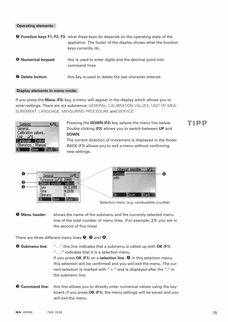
If you press the Menu (F3) key, a menu will appear in the display which allows you toenter settings. There are six submenus: GENERAL, CALIBRATION VALUES, UNIT OF MEA-
SUREMENT, LANGUAGE, MEASURING PROCEDURE and SERVICE.
Pressing the DOWN (F2) key selects the menu line below.Double clicking (F2) allows you to switch between UP andDOWN. The current direction of movement is displayed in the footer.BACK (F3) allows you to exit a menu without confirming new settings.
� Menu header: shows the name of the submenu and the currently selected menuline of the total number of menu lines. (For example, 2/5: you are inthe second of five lines)
There are three different menu lines �, � and �:
� Submenu line: “. . .“ this line indicates that a submenu is called up with OK (F1). “. . . :“ indicates that it is a selection menu.If you press OK (F1) on a selection line � in this selection menu,this selection will be confirmed and you will exit the menu. The cur-rent selection is marked with ” = ” and is displayed after the ”:” inthe submenu line.
� Command line: this line allows you to directly enter numerical values using the key-board. If you press OK (F1), the menu settings will be saved and youwill exit the menu.
�
�
�
�
Selection menu (e.g. combustible crucible)
Operating elements:
Display elements in menu mode:
TIPP
15IKA®- WERKE C200 03.08

In order to ensure that the appliance works properly, you must set some parameters thefirst time you use it.
MENU (F3)� UP/DOWN (F2) to "Language"� OK (F1)� UP/DOWN (F2) select desired language
(default: English)� OK (F1)� BACK (F3)
The set language will appear in the "Language" submenu line.
MENU (F3) � UP/DOWN (F2) to "General"� OK (F1) � UP/DOWN (F2) to "Date" � Enter the date in the format dd.mm.yyyy
(e.g: 06.12.2005) � OK (F1)� BACK (F3)
MENU (F3) � UP/DOWN (F2) to "General"� OK (F1) � UP/DOWN (F2) to "Time" � Enter the time in the format hh:mm:ss (e.g: 14:29:56)� OK (F1)� BACK (F3)
In order to calibrate the appliance you must state the exact calorific value of the calibra-tion substance used (usually benzoic acid).
MENU (F3) � UP/DOWN (F2) to "General" � OK (F1) � UP/DOWN (F2) to "Reference" � Enter the calorific value in the format xxxxx
(default: 26460)� OK (F1)� BACK (F3)
4.5 Configuring the system
Select language
Set date
Set time
Reference
16 IKA®- WERKE C200 03.08

Once you have calibrated the appliance, you will need to enter the calculated C-values(calibration values) of all the decomposition vessels used.
MENU (F3)� UP/DOWN (F2) to "Calibration values" � OK (F1)� UP/DOWN (F2) select desired decomposition vessel� Enter the C-value in the format xxxx (default: 1)� OK (F1)� BACK (F3)
See the advice in section 5.4 Calibration.
In addition to the configuration described in section 4.5, you can apply other settingswhich are not necessary for the correct functioning of the appliance or which are onlyrequired for special applications
If you are using a combustible crucible, you can enter this here. The value for the externalenergy QExternal1 will then be automatically reduced by 50 joules as no cotton thread isused. The combustible crucible itself must be weighed and the resulting calculated energyvalue manually entered under QExternal2 (see section . 6.3, �) so that it can be taken intoaccount as external energy when calculating the calorific value.
MENU (F3)� UP/DOWN (F2) to "General" � OK (F1)� UP/DOWN (F2) to "Combustible crucible" � OK (F1)� Select the options "with" oder "without"
(default: without) � OK (F1)� BACK (F3)
Calibration values
4.6 System settings
Combustible crucible
17IKA®- WERKE C200 03.08
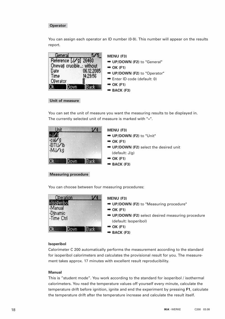
You can assign each operator an ID number (0-9). This number will appear on the resultsreport.
MENU (F3)� UP/DOWN (F2) to "General"� OK (F1)� UP/DOWN (F2) to "Operator" � Enter ID code (default: 0)� OK (F1)� BACK (F3)
You can set the unit of measure you want the measuring results to be displayed in.The currently selected unit of measure is marked with "=".
MENU (F3)� UP/DOWN (F2) to "Unit" � OK (F1)� UP/DOWN (F2) select the desired unit
(default: J/g)� OK (F1)� BACK (F3)
You can choose between four measuring procedures:
MENU (F3)� UP/DOWN (F2) to "Measuring procedure" � OK (F1)� UP/DOWN (F2) select desired measuring procedure
(default: Isoperibol)� OK (F1)� BACK (F3)
IsoperibolCalorimeter C 200 automatically performs the measurement according to the standardfor isoperibol calorimeters and calculates the provisional result for you. The measure-ment takes approx. 17 minutes with excellent result reproducibility.
ManualThis is ”student mode”. You work according to the standard for isoperibol / isothermalcalorimeters. You read the temperature values off yourself every minute, calculate thetemperature drift before ignition, ignite and end the experiment by pressing F1, calculatethe temperature drift after the temperature increase and calculate the result itself.
Operator
Unit of measure
Measuring procedure
18 IKA®- WERKE C200 03.08

DynamicCalorimeter C 200 performs the measurement automatically and calculates the provisio-nal result. The measuring time is reduced to approx. 8 minutes thanks to a dynamic cor-rection process. It is still possible, however, to meet the accuracy specifications of theinternational standards.
Time controlCalorimeter C 200 performs the measurement automatically according to a set period oftime and calculates the provisional result. The measuring time is set at 14 minutes.
Before using the calorimeter for the first time you must fill the outer vessel with tapwater.
Destilled and/or deactveted water may not be used!
To do this, pour two litres of tap water into the filler of tank � (see section 4.1) using themeasuring cup provided. The water must first be maintained at a constant temperature. To ensure accurate results,the initial temperature must not fluctuate too much.
Water temperature 18 °C - 25 °C with an accuracy of ±1 °C during a measurement series
You must now pump the water out of the tank into the outer vessel:
The equipment is in the stand by mode
MENUE (F3)� 1stFILL (F2)� Pumping procedure is started
Keep an eye on the water by pulling the filler of tank �(see section 4.1) out the top. When the overflow causesthe water to run back in the side of the tank, the outervessel is full and you must switch of the pump againby pressing STOP OK (F2) once more.
You should change the water if it has been sitting for a long time. See section 8.3.
4.7 Filling the calorimeter for the first time
TIPP
19IKA®- WERKE C200 03.08
In order to switch off the calorimeter system, the start screen must be displayed. Press OFF (F1). The appliance will switch to standby mode.
Only switch the appliance off in standby mode. To do this, press the ON/OFF switch �(see section 4.2) on the back of the appliance.
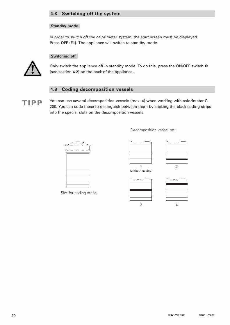
You can use several decomposition vessels (max. 4) when working with calorimeter C200. You can code these to distinguish between them by sticking the black coding stripsinto the special slots on the decomposition vessels.
4.8 Switching off the system
Standby mode
Slot for coding strips
1(without coding)
2
3 4
Decomposition vessel no.:
TIPP
Switching off
4.9 Coding decomposition vessels
20 IKA®- WERKE C200 03.08
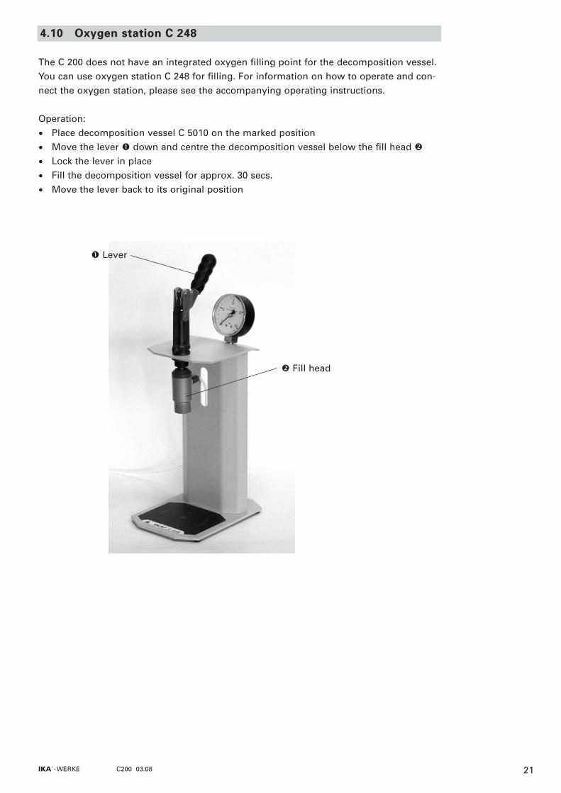
The C 200 does not have an integrated oxygen filling point for the decomposition vessel.You can use oxygen station C 248 for filling. For information on how to operate and con-nect the oxygen station, please see the accompanying operating instructions.
Operation:
• Place decomposition vessel C 5010 on the marked position
• Move the lever � down and centre the decomposition vessel below the fill head �
• Lock the lever in place
• Fill the decomposition vessel for approx. 30 secs.
• Move the lever back to its original position
4.10 Oxygen station C 248
� Lever
� Fill head
21IKA®- WERKE C200 03.08

Calorimetric measurements5
Combustion is carried out in a calorimeter under specific conditions. The decompositionvessel is filled with a weighed fuel sample, the fuel sample is ignited and the temperatureincrease in the calorimeter system measured. The specific calorific value of the sample iscalculated as follows:
Ho = (C * DT - QExternal1 - QExternal2) / m (1)
m Weight of fuel sampleC Heat capacity (C-value) of calorimeter systemDT Calculated temperature increase of water in inner vessel of measuring cellQExternal1 Correction value for the heat energy generated by the cotton thread as
ignition aidQExternal2 Correction value for the heat energy from other burning aids
The decomposition vessel is filled with pure oxygen (99.95 %) to optimise the combus-tion process. The pressure of the oxygen atmosphere in the decomposition vessel ismax. 30 bar. Formula (1) for the calorific value of a material requires that combustiontakes place under specifically defined conditions. The relevant standards are based onthe following assumptions:
• The temperature of the fuel and its combustion products is 25°C.
• The water contained in the fuel before combustion and the water formed whilst com-busting the hydrogenous compounds of the fuel is in fluid form after combustion.
• The atmospheric nitrogen has not oxidised.
• The gaseous products after combustion consist of oxygen, nitrogen, carbon dioxideand sulphur dioxide.
• Solid materials may form (e.g. ashes).
In many cases, however, not just the combustion products referred to in the standards areproduced. In such cases the fuel sample and the combustion products must be analysedto provide data for a revised calculation. The standard calorific value is then calculatedfrom the measured calorific value and the analysis data. The heat value Hu is the sameas the calorific value, minus the condensation energy of the water contained in the fueland formed through combustion. The heat value is the more important parameter from a technical point of view because in all major, technical applications only the heat valuecan be evaluated in terms of energy.The complete bases of calculation for the calorific and heat value can be found in therelevant standards (e.g.: DIN 51 900; ASTM D 240; ASTM D 5865..). They are also con-tained in the CalWin calorimeter software.
5.1 Determining the calorific value
22 IKA®- WERKE C200 03.08
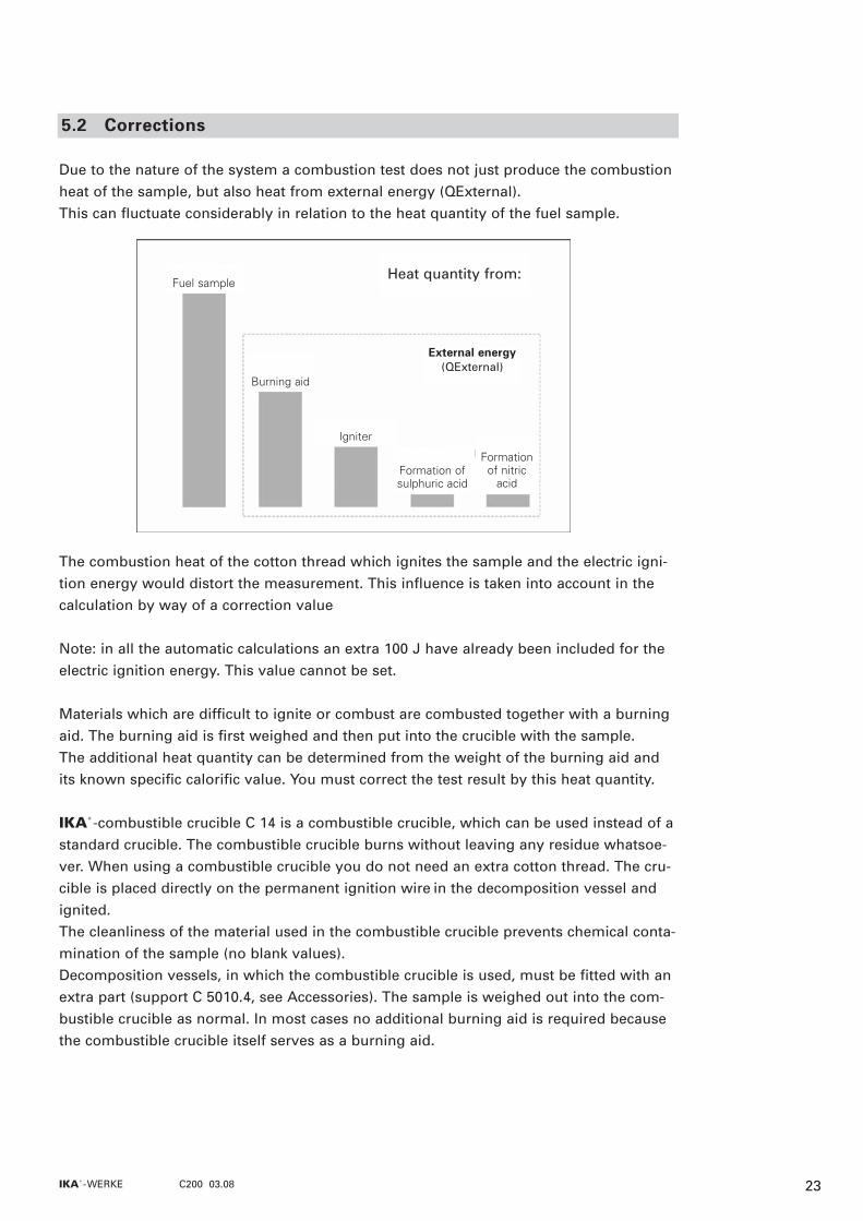
Due to the nature of the system a combustion test does not just produce the combustionheat of the sample, but also heat from external energy (QExternal).This can fluctuate considerably in relation to the heat quantity of the fuel sample.
The combustion heat of the cotton thread which ignites the sample and the electric igni-tion energy would distort the measurement. This influence is taken into account in thecalculation by way of a correction value
Note: in all the automatic calculations an extra 100 J have already been included for theelectric ignition energy. This value cannot be set.
Materials which are difficult to ignite or combust are combusted together with a burningaid. The burning aid is first weighed and then put into the crucible with the sample. The additional heat quantity can be determined from the weight of the burning aid andits known specific calorific value. You must correct the test result by this heat quantity.
IKA®-combustible crucible C 14 is a combustible crucible, which can be used instead of astandard crucible. The combustible crucible burns without leaving any residue whatsoe-ver. When using a combustible crucible you do not need an extra cotton thread. The cru-cible is placed directly on the permanent ignition wire in the decomposition vessel andignited.The cleanliness of the material used in the combustible crucible prevents chemical conta-mination of the sample (no blank values).Decomposition vessels, in which the combustible crucible is used, must be fitted with anextra part (support C 5010.4, see Accessories). The sample is weighed out into the com-bustible crucible as normal. In most cases no additional burning aid is required becausethe combustible crucible itself serves as a burning aid.
5.2 Corrections
(QFremd)
Fuel sample
Burning aid
Igniter
Formation of sulphuric acid
Formationof nitricacid
External energy (QExternal)
Heat quantity from:
23IKA®- WERKE C200 03.08

Virtually all of the materials to be studied contain sulphur and nitrogen. Under the condi-tions in calorimetric measurements, sulphur and nitrogen combust to SO2, SO3 and NOx.Together with the water from combustion and moisture, sulphuric and nitric acid as wellas heat of solution are produced. In order to obtain the standard calorific value, the in-fluence of the heat of solution on the calorific value is corrected. The calculation formulaedepend on the standard used. These are not taken into account in the calculation for C 200. Use IKA®’'s CalWin software for this.
It is essential that the sample fully combusts to ensure correct determination of the calo-rific value. After each experiment check the crucible and all the solid residue for signs ofincomplete combustion.
As a rule the weighted sample must be selected in such a way that the temperatureincrease during the measurement is below 4 K and comes close to the temperature incre-ase of the calibration (max. extra energy: 40,000 J).
Normally solid materials in powder form can be combusted directly. Materials whichcombust quickly (e.g. benzoic acid) must not be burnt loose. These materials tend tosplash and there is therefore no guarantee of complete combustion. Furthermore, thiscan damage the inner wall of the decomposition vessel. IKA® pelleting press C 21 andIKA® analytical mill A11 basic (see Accessories) are available for sample preparation.
Materials which are difficult to burn (materials with a high mineral content, low caloricmaterials) can often only be fully combusted using IKA® acetobutyrate capsules C 10,IKA® combustion bags C 12 or IKA® combustible crucible C 14 (see Accessories). It isalso possible to use liquid burning aids such as paraffin oil.
Before filling the capsule or the combustion bag with the substance to be determined,weigh them to calculate the extra external energy added by the burning aid from theweight and the calorific value. This must be taken into account in QExternal2. You shouldkeep the amount of burning aid used to a minimum.
Most fluid substances can weighed out directly into the crucible. Highly volatile substan-ces are poured into combustion capsules (IKA® gelatine capsules C 9 or IKA® acetobuty-rate capsules C 10, see Accessories) and combusted together with the capsules.
The burning aids (e.g. cotton thread) must also fully combust. If there is any unburntresidue, the test must be repeated.
5.3 Information about the sample
24 IKA®- WERKE C200 03.08
When working with unknown substances, select very small weighted samples at the startin order to determine the natural energy. If you are burning unknown samples, leave theroom or keep your distance from the calorimeter.
After combustion the water produced is collected and the decomposition vessel is tho-roughly rinsed with distilled water. The water used for rinsing and the solution producedare combined and examined for their acidity. If the sulphur content of the fuel and thenitric acid correction are known, it is not necessary to analyse the water.
The calorimeter system must be calibrated before accurate measurements are possible.This is done by combusting tablets made of certified benzoic acid (see Accessories) witha known calorific value. The heat quantity required to raise the temperature of the calori-meter system by one Kelvin is used to determine the heat capacity of the so-called "C-value" of the system. For this calculation the formula (1) (see section 5.1) is adapted:
C = (Ho * m + QExternal1 + QExternal2) / DT (2)
This value is used for determining the following calorific values.The heat capacity is determined by the measuring cell and the decomposition vessel (DV).It has a significant influence on the calorific value to be calculated and must be redeter-mined in particular when using for the first time, after servicing and when parts are re-placed. A monthly control measurement is recommended.
The system must be calibrated in every work mode used.
If a calorimeter is operated with several decomposition vessels, you will need to deter-mine the heat capacity of the system for each decomposition vessel.
Ensure that calibration is carried out under the same conditions as the subsequent tests.If substances are used in the decomposition vessel in combustion tests (e.g. distilled wa-ter or solutions), you must use exactly the same amount of this substance for calibration.
For more detailed information on calibration, please see the relevant standards.
5.4 Calibration
25IKA®- WERKE C200 03.08

Preparing and performing measurements6
The term "measurements" below refers to both the measurements to calibrate the calori-meter system (calibration measurements) and the actual measurements for determiningthe calorific value. The difference lies in the calculation (cf. section 5, formulae (1) and (2)),whereas preparation and performance are virtually identical.Exact measurements are only possible when the individual test steps are carried out care-fully.YYoouu mmuusstt tthheerreeffoorree ffoollllooww tthhee eexxaacctt pprroocceedduurree ddeessccrriibbeedd iinn sseeccttiioonn 11 ""FFoorr yyoouurr ssaaffeettyy”” aanndd iinn
tthhee ffoolllloowwiinngg sseeccttiioonnss
Please also see section 5 "Calorimetric measurements”
Failure to observe these instructions could result in damage to the decomposition ves-sel. Damaged decomposition vessels could crack! Follow the operating instructions forthe decomposition vessel!
If several decomposition vessels are used, their individual parts must not be interchan-ged (see Stamping individual parts).
To prolong the life of wearing parts (o-rings, seals, etc.) we recommend that you alwayswork with a water trap.
� Union nut
� Oxygen valve
� Cover
� Crucible
Crucible holder
� Electric ignition contact
� Ignition wire
6.1 Decomposition vessel C 5010
26 IKA®- WERKE C200 03.08

Prepare the decomposition vessel as follows
� Unscrew the union nut and removethe cover using the handle
� Attach a cotton thread tothe centre of the ignition wireusing a loop
� Weigh out the substance directly into the crucible with an accuracy of 0.1 mg. Notethe weight or enter directly into the calorimeter. (See section 6.3 "Preparing themeasurement")
� Insert the crucible into the crucible holder
If necessary put some distilled water or a solution into the decomposition vessel.
See section 5.3 "Information about the sample" and section 1 "Safety precautions”.
� Using tweezers, align the cotton thread so that it hangs inside the crucible and isimmersed in the sample. This will ensure that the burning thread ignites the sampleduring the ignition process.
� Place the cover onto the lower section and push down until it presses against thestop piece in the lower section. Place the union nut onto the lower section and tightenby hand.
6.2 Preparing the decomposition vessel
Handle � Cover
� Union nut
� Cotton thread
27IKA®- WERKE C200 03.08
max
. 1m
m
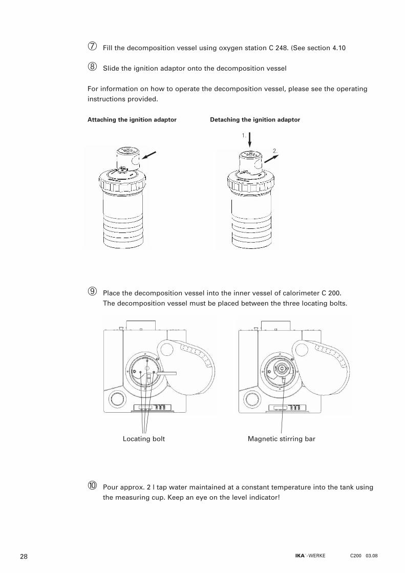
� Fill the decomposition vessel using oxygen station C 248. (See section 4.10
� Slide the ignition adaptor onto the decomposition vessel
For information on how to operate the decomposition vessel, please see the operatinginstructions provided.
Attaching the ignition adaptor Detaching the ignition adaptor
Place the decomposition vessel into the inner vessel of calorimeter C 200.The decomposition vessel must be placed between the three locating bolts.
Pour approx. 2 l tap water maintained at a constant temperature into the tank usingthe measuring cup. Keep an eye on the level indicator!
1.
2.
Locating bolt Magnetic stirring bar
28 IKA®- WERKE C200 03.08
29
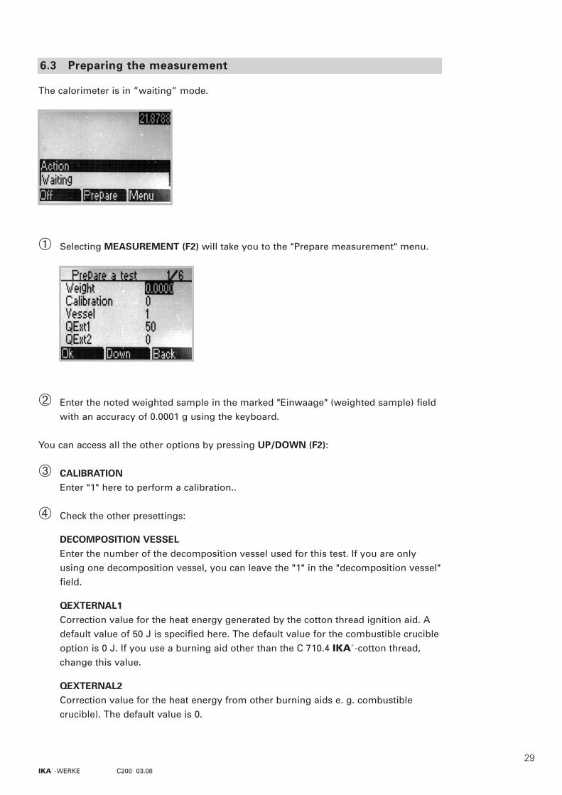
The calorimeter is in ”waiting” mode.
� Selecting MEASUREMENT (F2) will take you to the "Prepare measurement" menu.
� Enter the noted weighted sample in the marked "Einwaage" (weighted sample) fieldwith an accuracy of 0.0001 g using the keyboard.
You can access all the other options by pressing UP/DOWN (F2):
� CALIBRATIONEnter "1" here to perform a calibration..
� Check the other presettings:
DECOMPOSITION VESSELEnter the number of the decomposition vessel used for this test. If you are onlyusing one decomposition vessel, you can leave the "1" in the "decomposition vessel"field.
QEXTERNAL1Correction value for the heat energy generated by the cotton thread ignition aid. Adefault value of 50 J is specified here. The default value for the combustible crucibleoption is 0 J. If you use a burning aid other than the C 710.4 IKA®-cotton thread,change this value.
QEXTERNAL2Correction value for the heat energy from other burning aids e. g. combustible crucible). The default value is 0.
6.3 Preparing the measurement
IKA®- WERKE C200 03.08
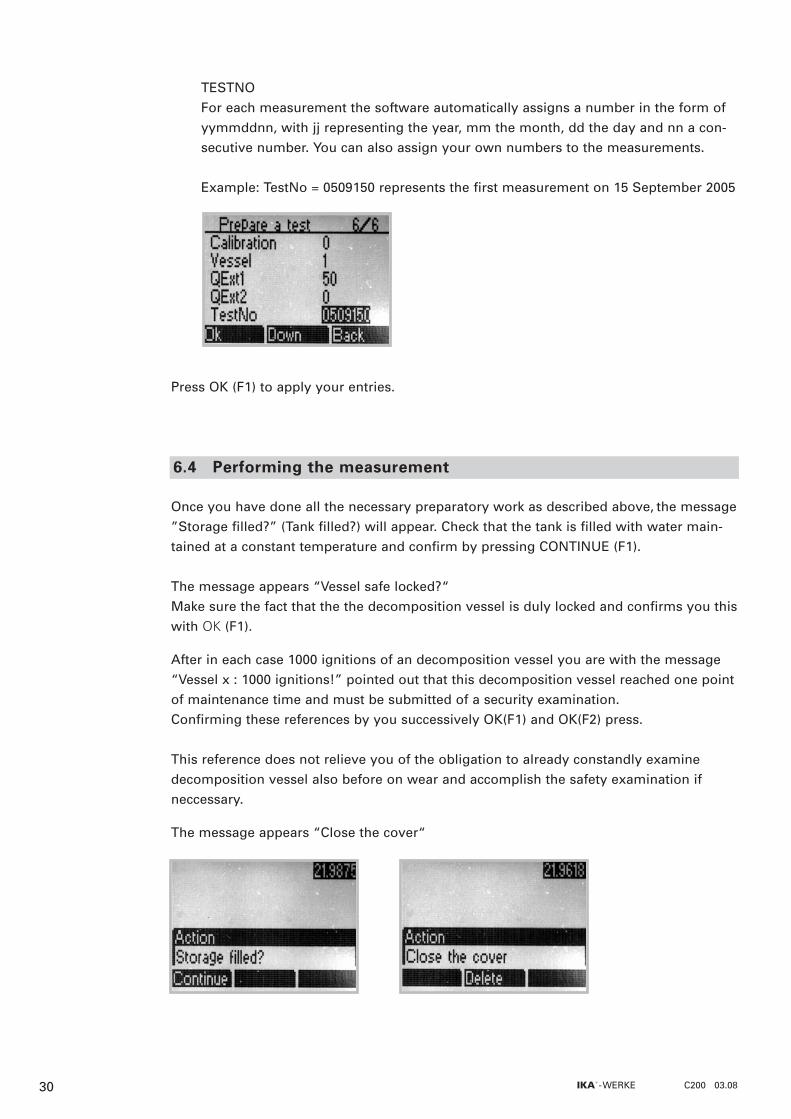
TESTNOFor each measurement the software automatically assigns a number in the form ofyymmddnn, with jj representing the year, mm the month, dd the day and nn a con-secutive number. You can also assign your own numbers to the measurements.
Example: TestNo = 0509150 represents the first measurement on 15 September 2005
Press OK (F1) to apply your entries.
Once you have done all the necessary preparatory work as described above, the message”Storage filled?” (Tank filled?) will appear. Check that the tank is filled with water main-tained at a constant temperature and confirm by pressing CONTINUE (F1).
The message appears “Vessel safe locked?“Make sure the fact that the the decomposition vessel is duly locked and confirms you thiswith OK (F1).
After in each case 1000 ignitions of an decomposition vessel you are with the message“Vessel x : 1000 ignitions!” pointed out that this decomposition vessel reached one pointof maintenance time and must be submitted of a security examination.Confirming these references by you successively OK(F1) and OK(F2) press.
This reference does not relieve you of the obligation to already constandly examinedecomposition vessel also before on wear and accomplish the safety examination ifneccessary.
The message appears “Close the cover“
6.4 Performing the measurement
30 IKA®- WERKE C200 03.08

� Close the cover by moving it to the left out of the locking position until it slidesdown by itself. The decomposition vessel comes into contact with the igniters viathe ignition adaptor.The "Fill" message will appear.
� The inner vessel will be filled with water (approx. 70 s). The measurement processwill begin as soon as it is full.
� a) The measurement process is fully automatic for automatic measuring procedures(isoperibol, dynamic and time-controlled, see section 4.6). The result will appearonce the measuring process is complete
¬ b) With the manual measuring procedure the user decides when ignition is to takeplace and when the measurement is complete.
· To start ignition press IGNITE (F1)· Press the same key END (F1) again to end
the measurement
31IKA®- WERKE C200 03.08

In the case of manual ignition / completion, "Preparing to ignite" or „Preparing tocomplete" will appear in the status line. Ignition/completion is only finished whenthis display disappears (max. 60 sec.).
� After the measurement open the cover to automatically empty the inner vessel. Remove the decomposition vessel and the ignition adaptor. To release tension in thedecomposition vessel use venting button under a fume hood or venting station C 5030 available in our accessories range. See also section 1 "Safety precautions".
� Open the decomposition vessel and check the crucible for signs of incomplete com-bustion. If combustion is incomplete, discard the test result. Repeat the test.
If you suspect that the combustion sample, the combustion gases produced or the com-bustion residue could be harmful to health, wear personal protective equipment (e.g.protective gloves, breathing masks) when handling these materials. Harmful or pollutingcombustion residue must be disposed of as hazardous waste. Express reference is madeto the applicable regulations.
In order to obtain accurate measurements it is essential that the decomposition vessel isclean and dry. Impurities alter the heat capacity of the decomposition vessel and thuscause inaccurate measuring results. It is important to thoroughly clean the inner walls ofthe vessel, the internal fittings (brackets, electrodes etc.) and the combustion crucible(inside and out!) after each combustion test.
In most cases, you will only need to remove condensate from the inner walls of the ves-sel and the internal fittings. It is sufficient to thoroughly wipe the parts with an absor-bent, non-fibrous cloth. If the decomposition vessel cannot be cleaned in the above way(e.g. due to baking, pitting, corrosion etc.), please contact the Technical Service.
The combustion residue in the crucible, e.g. soot or ashes, should also be wiped awaywith an absorbent non-fibrous cloth.
6.5 Cleaning the decomposition vessel
32 IKA®- WERKE C200 03.08

Errors in the measuring procedure are shown in the alarm line of the display and remainthere until they are appropriately acknowledged by the user.
Message: Cover open
Cause: the cover was opened during the measuring process.User action: the inner vessel will be emptied automatically, after which a new
measurement can be started.Note: if the cover was opened within a minute of ignition, automatic
emptying will be delayed by approx. 2 mins for safety reasons.
Cause: no ignition contact during the measurement.User action: open the cover and check the ignition wire and ignition contacts.
If necessary, clean the ignition contacts or change the ignition wire.Check that the ignition adaptor is in the right position.
Message: No temperature increase(appears if the value specified for the temperature increase is not reached within one minute of ignition (0.05 K).
Cause: sample not combusted. (Cotton thread had no contact to sample)
User action: open cover and remove decomposition vessel. If the cotton thread hasnot combusted, check the ignition contacts and the ignition wire.Otherwise, start a test and use ignition aid if necessary
Cause: decomposition vessel may not have been filled with oxygen.User action: open the cover to cancel the test and perform a new measurement
6.6 Errors in the measuring procedure
33IKA®- WERKE C200 03.08

Message: A/D converter error
Cause: an error has occurred in the temperature measuring system.User action: if the measurement is still active, open the cover to cancel the test.
Then reinitialise the converter (see section 7.2 ”ReInit”). If this does not work, switch the appliance off and then back on again.If this does not work either, please contact IKA®-Service.
Message: Fill time exceeded
Cause: no water in tankUser action: check the fill level in the tank and top up with water if necessary.
Press CONTINUE (F1) to repeat the filling process and continue themeasurement.
Cause: filter in inner vessel is dirty.User action: open the cover to cancel the test. Remove and clean the inner vessel
filter.
Cause: pump for filling inner vessel is not workingUser action: open the cover to cancel the test. Switch on the pump in the service
menu (see section 7.2 ”Pump”) and check water jet in tank. If there isno water flow, please contact IKA®-Service.
34 IKA®- WERKE C200 03.08

Message: Start temperature outside
Cause: start temperature of inner vessel is not in range 22 ± 3 °CUser action: open cover to cancel measurement, or press CONTINUE (F1) to
continue the measurement anyway. Note: a measuring result obtained in this way does not correspond to the
standard conditions User action: check the water temperature for the tank. Check the temperature
shown. If it does not change within 5 to 10 secs, reinitialise the A/Dconverter. (See section 7.2 ”ReInit”)
Message: Drift unstable
Cause: there is no magnetic rod in the inner vessel or the magnetic rod is outside of the magnetic field.
User action: open the cover to cancel the test and check the position of the magnetic rod. If necessary, insert the rod or position properly. (See section 6.2, »)
Cause: the stirrer is not working.User action: open the cover to cancel the test. Half fill the inner vessel with water
(via Service menu see section 7.2) and then manually switch the stir-ring motor on and off (also via Service menu). If the stirring motordoes not work, please contact IKA® Service.
35IKA®- WERKE C200 03.08

Service menu7
This menu allows you to directly control and test various actions and statuses of thecalorimeter without performing a measurement. There are also menu items which can beused to start up and shut down the appliance. The service menu can only be run if thecalorimeter displays the start screen.
Perform the desired action using:
MENU (F3)� UP/DOWN (F2) to "Service" � OK (F1)There are now eight actions to choose from
· select the desired action with UP/DOWN (F2)� OK (F1) starts the action� OK (F1) stops the action again
Please note that you must stop every started action.
Exceptions: The "Ignite” action ends automatically after a set time period (approx. 2 seconds).With actions "Reset” and "ReInit” you will automatically exit the menu after the actions have been performed.
If you exit the service menu, all the started actions will be stopped and the system will berestored to its original state. This will allow you to continue without any errors.
7.1 Operation
36 IKA®- WERKE C200 03.08

This menu item allows you to check the ignition function Requirement: there must be a decomposition vessel without sample, but with ignition
thread in the inner vessel and the cover must be closed.
This menu item allows you to fill the inner vessel manually.Requirement: there must be enough water in the tank.
This menu item allows you to empty the inner vessel.Requirement: the emptying hose must be locked in place in the plug-in coupling
(section 4.2).
This menu item allows you to switch on the stirrer drive and check that the magnetic rodis also rotating in the inner vessel. Requirement: there must be approx. 0.5 l water in the inner vessel
Switch the pump on with this menu item. The outer vessel will be filled and rinsed. (See also section 4.7)Requirement: check that there is water in the tank.
This menu item allows you to empty the outer vessel. Note: shut-down, completely empty applianceRequirement: the emptying hose must be locked in place in plug-in coupling
(section 4.2)
This menu item allows you to restore the default settings.
This menu item allows you to reinitialise the A / D converter.
7.2 Description of service menu options
Ignition
Fill IV
Empty IV
Stirrer
Pump
Empty outer vessel
Reset
Reinit
37IKA®- WERKE C200 03.08
Cleaning and maintenance8
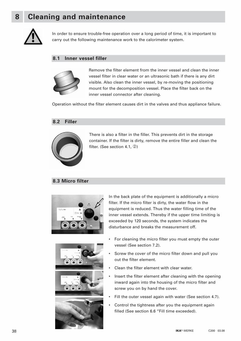
In order to ensure trouble-free operation over a long period of time, it is important tocarry out the following maintenance work to the calorimeter system.
Remove the filter element from the inner vessel and clean the innervessel filter in clear water or an ultrasonic bath if there is any dirtvisible. Also clean the inner vessel, by re-moving the positioningmount for the decomposition vessel. Place the filter back on theinner vessel connector after cleaning.
Operation without the filter element causes dirt in the valves and thus appliance failure.
There is also a filter in the filler. This prevents dirt in the storagecontainer. If the filter is dirty, remove the entire filler and clean thefilter. (See section 4.1, �)
8.3 Micro filter
8.2 Filler
8.1 Inner vessel filler
38 IKA®- WERKE C200 03.08
In the back plate of the equipment is additionally a microfilter. If the micro filter is dirty, the water flow in theequipment is reduced. Thus the water filling time of theinner vessel extends. Thereby if the upper time limiting isexceeded by 120 seconds, the system indicates thedisturbance and breaks the measurement off.
• For cleaning the micro filter you must empty the outervessel (See section 7.2).
• Screw the cover of the micro filter down and pull youout the filter element.
• Clean the filter element with clear water.
• Insert the filter element after cleaning with the openinginward again into the housing of the micro filter andscrew you on by hand the cover.
• Fill the outer vessel again with water (See section 4.7).
• Control the tightness after you the equipment againfilled (See section 6.6 “Fill time exceeded).

In the case of discontinuous use with tap water (single measurements with long gaps) astabiliser must be added to the water circulation to prevent the formation of algae.Add approx. 4 ml IKA®-Aqua-Pro C 5003.1 to the tank (see Accessories). Switch the pumpon via the service menu (section “Pump“). Switch the pump off again after 30 - 60 s.
You can also add the 4 ml Aqua-Pro to the water maintained at a constant temperature inthe last measurement. (Before long gaps in measuring)
If the appliance is not going to be in operation for a long period of time, it is advisableto completely empty the calorimeter's water circulation.The water must be drained out before transportation.
Empty the outer vessel via the service menu (section 7.2 “Outer vessel“). The emptyinghose must be locked in place in the plug-in coupling (section 4.2).
Empty the tank by locking the emptying hose in place in the plug-in coupling �(section 4.2). ). The tank will empty automatically.Press the locking knob on the plug-in coupling � to remove the hose.
Please see the operating instructions for C 5010 for information on decomposition vessel maintenance!
Only clean IKA® appliances using these IKA® approved cleaning agents:
Dirt Cleaning agent
Dyes Isopropanol
Building materials Water containing detergent, isopropanol
Cosmetics Water containing detergent, isopropanol
Food Water containing detergent
Fuels Water containing detergent
Other materials Please consult IKA®
Comment:Do not place electrical appliances into the cleaning agents for cleaning purposes.Stainless steel parts can be cleaned using standard stainless steel cleaning agents, butdo not use abrasives.We recommend that you wear protective gloves for cleaning.The operator is responsible for ensuring appropriate decontamination in the event thatdangerous material is spilt onto or into the appliance.Before using a cleaning or decontamination method other than that recommended bythe manufacturer, check with the manufacturer that the intended method will not destroythe appliance.
TIPP
8.4 Maintaining the water circulation
8.6 Cleaning information
8.5 Decomposition vessels
39IKA®- WERKE C200 03.08
40 IKA®- WERKE C200 03.08
IKA® accessories and consumables9
C 5010 Decomposition vessel, standardC 5010.4 Support for combustible crucibleC 5010.5 Support for large crucibleC 5030 Venting stationC 5040 CalWin®, calorimeter softwareC 248 Oxygen stationC 21 Pelleting pressC 29 Reducing valveC 200.1 Measuring cupA 11 basic Analytical mill
C 710.4 Cotton thread, cut to length (500 x)C 5010.3 Ignition wire, replacement (5 x)C 5003.1 Aqua-Pro bath stabiliser (30 ml)C 4 Quartz dishC 5 VA combustion crucible set (25 x)C 6 Quartz dish, largeC 710.2 VA combustion crucible set, large (25 x)C 9 Gelatine capsules (100 x)C 10 Acetobutyrate capsules (100 x)C 12 Combustion bag, 40 x 35 mm (100 x)C 12A Combustion bag, 70 x 40 mm (100 x)C 43 Benzoic acid (NBS 39i, 30 g)C 43A Benzoic acid (100 g)C 723 Benzoic acid blister pack (50 x)C 14 Combustible crucible (100 x)C 15 Paraffin strips (600 x)
9.1 Accessories
9.2 Consumables

41IKA®- WERKE C200 03.08
Technical data10
Table power supply (external):
Rated voltage/frequency
Input power max.
Calorimeter:
Rated voltage
Input power max..
Fuses (internal)
On-time
Protection class as per DIN EN 60 529
Protection class
Overvoltage category
Level of contamination
Ambient temperature
Ambient humidity
Use above sea level
Size
Weight
Measurement ranges
Measuring mode / measurement times:
Interfaces
100 - 240 V AC 50 / 60 Hz
120 W
24 V DC 5A
100 W
1x 2.5 AT
Continuous operation
IP 20
III
2
II
20 °C ... 25 °C (constant)
80%
2000 m above sea level
400 x 400 x 400 (W x D x H)
21 kg
40,000 J
Isoperibol / approx. 17 min
Dynamic / approx. 8 min
Time control / 14 min
Manual / approx. 17 min
1 x parallel (Centronics)
1 x serial (RS 232)
Subject to technical change!

42 IKA®- WERKE C200 03.08

43IKA®- WERKE C200 03.08

North AmericaAsiaAustralia
EuropeMiddle EastAfrica
IKA®- WerkeGmbH & Co.KGJanke & Kunkel-Str. 10D-79219 StaufenTel.: +49 7633 831-0Fax: +49 7633 831-98E-Mail: [email protected]
IKA® Works, Inc.2635 North ChasePkwy SEWilmingtonNC 28405-7419 USATel.: 800 733-3037Tel.: +1 910 452-7059Fax: +1 910 452-7693E-Mail: [email protected]
China
IKA® Works Guangzhou173-175 Friendship RoadGuangzhouEconomic and TechnologicalDevelopment District510730 Guangzhou, ChinaTel.: +86 20 8222-6771Fax: +86 20 8222-6776E-Mail: [email protected]
Japan
IKA® Japan K.K.293-1 Kobayashi-choYamato Koriyama Shi, Nara639-1026 JapanTel.: +81 743 58-4611Fax: +81 743 58-4612E-Mail: [email protected]
IKA® Works (Asia)Sdn BhdNo. 17 & 19, Jalan PJU 3/50Sunway Damansara Technology Park47810 Petaling JayaSelangor, MalaysiaTel.: +60 3 7804-3322Fax: +60 3 7804-8940E-Mail: [email protected]
Korea
IKA® Korea Co LTD1710 Anyang Trade Center1107 Buhung-dong,Dongan-guAnyang City, Kyeonggi-doPost code: 431-817South KoreaTel.: +82 31-380-6877Fax: +82 31-380-6878E-Mail: [email protected]
India
IKA®- WerkeGmbH & Co.KGLiaison Office IndiaNo. 31 (Old No. 264) 1st Floor, 10th Cross1st “N” Block, Rajajinagar560 010 BangaloreTel.: +91 80-41157736Fax: +91 80-41157735E-Mail: [email protected]
Brasilia
IKA®Works Inc.Av. das Américas,15700, sala 235Recreio dos BandeirantesCEP 22790-701Rio de Janeiro, RJBrasilTel.: +55 21 2487-7743Fax: +55 21 2487-7743E-Mail: [email protected]
00/0000/0